Embed Size (px)
Citation preview

Investigating the effect of PID controller on inertial response in doublyfed induction generator (DFIG)
Ahmad, T., Littler, T., & Naeem, W. (2016). Investigating the effect of PID controller on inertial response indoubly fed induction generator (DFIG). In 2016 UKACC 11th International Conference on Control (CONTROL)IEEE . DOI: 10.1109/CONTROL.2016.7737562
Published in:2016 UKACC 11th International Conference on Control (CONTROL)
Document Version:Peer reviewed version
Queen's University Belfast - Research Portal:Link to publication record in Queen's University Belfast Research Portal
Publisher rightsCopyright 2017 IEEE. This work is made available online in accordance with the publisher’s policies. Please refer to any applicable terms ofuse of the publisher.
General rightsCopyright for the publications made accessible via the Queen's University Belfast Research Portal is retained by the author(s) and / or othercopyright owners and it is a condition of accessing these publications that users recognise and abide by the legal requirements associatedwith these rights.
Take down policyThe Research Portal is Queen's institutional repository that provides access to Queen's research output. Every effort has been made toensure that content in the Research Portal does not infringe any person's rights, or applicable UK laws. If you discover content in theResearch Portal that you believe breaches copyright or violates any law, please contact [email protected].
Download date:28. May. 2018
Investigating the effect of PID controller on inertial
response in doubly fed induction generator (DFIG)
Thelfa Ahmad1, Tim Littler2, Wasif Naeem3
School of Electronics, Electrical Engineering and Computer Science
Queen's University Belfast, Belfast, UK
[email protected], [email protected], [email protected]
Abstract— The increasing penetration of wind generation
impacts the reliability and stability of power systems. This paper
investigates and analyses the effect of PID controller parameters
on the inertial response of a doubly fed induction generator
(DFIG) wind turbine to support the frequency control of a power
system in the event of sudden power changes. The goal of this
review is to extensively determine the effect of PID parameters to
compare and set a benchmark so that an adaptive control
strategy can be developed for frequency regulation. A
conventional inertial controller algorithm using the rate of
change of frequency (RoCoF) and frequency deviation loops was
investigated whilst the contribution of the DFIG to system
inertial response and frequency control are examined. The paper
considers the influence of supplementary inertial control loop
parameters on the inertial response and power system frequency.
The results indicate that the DFIG inertial controller scheme is
able to provide appropriate frequency support.
Keywords—wind energy generation; doubly-fed induction
generator (DFIG); frequency control; inertia; kinetic energy; rate
of change of frequency (RoCoF).
I. INTRODUCTION
The challenge and necessity of a reduction in CO2 emissions due to climate change concerns, as well as security and shortage of supplies such as fossil fuels, has meant that many countries have made commitments to increase the penetration of non-conventional and renewable generation, thus displacing centralized generation from traditional fuel sources, such as coal, oil and gas. Large-scale integration of alternate energy sources, although beneficial, can have unpredictable consequences which can challenge the stability of existing power systems, not least with widespread integration of wind power generation. In an electric power system, electrical generation must meet expected power demand and as such, power supply must be continuously balanced: power imbalance occurs as a result of mismatch between generation and load. Consequently, frequency change will arise and consideration of the RoCoF in particular is important because it is a problem that can lead to additional losses of generation and increase the risk of a potential system collapse. Though minor mismatches exist on the grid, a significant imbalance in either magnitude or time span can be catastrophic for power systems, possibly resulting in black-out or equipment damage. The major advantages of wind energy include sustainability, minimal CO2 impacts, and a more reliable source in comparison with other renewable energy
resources. Wind energy has developed rapidly over the last 25 years and is one of the most prominent renewable sources of electricity across the world [1].
Recently there has been an increased interest in doubly fed induction generator (DFIG) based wind turbines due to their wider operating range and efficiency across a range of wind velocities. Thus they are capable of a delivering power output at different wind speeds [2] . Many of the large wind turbines that are now commercially available are DFIG units. Operating a large number of DFIG based wind turbines can displace conventional synchronous generation and this in turn creates a range of new problems such as reducing system inertia and increasing the potential for greater RoCoF. In effect, this reduces the ability to control the frequency of the system due to the fact that the DFIG control system decouples the mechanical and electrical systems, thus preventing the generator from responding to system frequency changes. This is undesirable when there are a large number of DFIG wind turbines operating, especially in periods of low load and on smaller power systems (e.g., Ireland) [3].
The frequency of a power system with low inertia will certainly change rapidly for abrupt variations in generation or load, which reduces the control margin for system frequency. Therefore, modern variable speed wind turbines (VSWTs) do not participate in control of the system frequency. However, this problem should be solved properly to ensure reliable and stable operation of the power grid.
Since the PID is an implicit element of DFIGs, this paper provides a timely review of the role of this controller in preserving inertia. This study therefore provides an investigation of the effect of the proportional-integral-derivative (PID) controller parameters on system inertial response. Section 1 analyses the benefits of the fast response capability of a DFIG with no supplementary inertial control in the power control loop. With a supplementary loop added to the standard power control loop, the DFIG is shown to exhibit inertial response. The influence of controller parameters for different values is investigated in Section 2. Section 3 compares the RoCoF and frequency deviation loops based on their effect on system frequency and the DFIG wind turbine. Literature published to date indicates that limited work has investigated the effect of changing controller parameters. However this paper concludes that significant performance
improvement can be made by appropriate adjustment of inertial controller parameters.
II. FREQUENCY CONTROL
The purpose of any control system is to maintain the output of
a system at a specified value. In the case of power system
frequency control, the objective is to tightly govern this
primary parameter close (+/- 1%) to the nominal frequency
(49.5 – 50.1, UK), [1]. Network frequency will change when
the total active power generation differs from the total active
power required by the load in the network. The system
frequency is controlled by balancing the generation of power
against load demand on a second-by-second basis.
Conventional power plant with synchronous generation has
the inherent capability to control the frequency, because it has
a significant inertia constant [4].
The response duties of a conventional power plant can be split
into primary and secondary responses. The primary and
secondary responses are defined as the additional active power
delivered by automatic governor action from a generating unit
that is available at 10 seconds and 30 seconds, respectively
after the event and which can be sustained for 20 seconds to
30 minutes [5]. Frequency deviations of < 0.05 Hz are usually
considered small although these could be significant
depending on interconnection and operating conditions. The
IEEE recommends that frequencies within ±0.036 Hz around
the nominal frequency be considered as nominal [6].
Usually wind turbines operate to maximize their output power
under all possible conditions. Consequently the DFIG cannot
provide any further increase in active power output and
therefore participate in secondary response services of
frequency deviation which conventional generators can do.
However, a DFIG can provide transient primary frequency
control in the interconnected power system by utilizing the
kinetic energy in the inertia of DFIG [7].
III. PID CONTROLLER
A PID controller is by far the most common control algorithm
feedback loop in practice. The controller takes a measured
value from a process or other apparatus and compares it with a
reference set point value. The difference (or “error” signal) is
then used to adjust some input to the process in order to bring
the process (“measured”) value back to its desired set point.
The PID controller adjusts the process output based on the
history (integral) and rate of change (derivative) of the error
signal, which gives more accurate and stable control [8]. In the
following, a brief discussion of each of the three PID terms is
provided from the perspective of application to a power
system.
A. Derivative Term:
The derivative action predicts system behavior and thus
improves settling time and stability of the system. The
magnitude of the contribution of the derivative term to the
overall control action is represented by the derivative gain, Kd
[8]. This slows the rate of change of the controller output and
therefore reduces the magnitude of the overshoot (produce by
the integral action). The effect of Kd is most noticeable close
to the controller set point.
In power systems, the derivative term acts to increase the
decelerating torque of the wind turbine rotor speed
(proportional 𝑑𝑓 𝑑𝑡⁄ ) to reduce rate-of-change of frequency
and improve the stability. This control induces a temporary
wind turbine inertial response and makes the wind turbine
respond to frequency disturbances. The additional power
output (P) from the kinetic energy (E) of DFIG wind turbine
can be written as, [3],
𝑃 =𝑑𝐸
𝑑𝑡= 𝐽𝑤
𝑑𝑤
𝑑𝑡 (1)
where 𝑃, 𝐸, 𝐽 and 𝑤 represent additional power output of the
wind turbine, the kinetic energy stored in the rotating mass of
the wind turbine, the moment of inertia of the wind turbine
and the rotational speed of DFIG, respectively.
When there is a reduction in the power system frequency from
its operating value, the speed of the generator starts to drop.
This can be considered as a deceleration torque 𝑇𝑑𝑒𝑐 , acting on
the on the rotating mass. The rotor speed of the DFIG can
usually vary between 0.8p.u and 1.2P.u. The kinetic energy
from the rotating mass of wind turbine is released rapidly
through the power electronic converter. The decelerating
torque can be constructed by differentiating the kinetic energy
(1 2𝐽𝑤2⁄ ) released by the mass and then by dividing the
equivalent power by the rotation speed w. Therefore the
decelerating torque is proportional to 𝑑𝑤 𝑑𝑡 ⁄ and thus
to 𝑑𝑓 𝑑𝑡.⁄ This reduces the rate of change of frequency and
helps increase the frequency nadir [9].
B. Proportional Term:
A higher proportional controller gain (Kp) will have the effect
of reducing the rise time and will reduce but never eliminate
the steady-state error. As the gain is increased, the response
will become faster but at the cost of higher overshoot in the
output response [8].
In power systems, this controller represents the governor or
droop control. This control strategy is similar to the primary
frequency control used in conventional generators. The
amount of additional active output power produced by the
wind turbine is proportional to the difference between the
measured and the nominal frequency. The droop controller
regulates the active power output and greatly improves the
frequency nadir and also the frequency recovery process
following a disturbance [10].
C. Integral Term:
The contribution from the integral term is proportional to both
the magnitude and duration of the error. The integral term
accelerates the movement of the process towards the set point
and eliminates the residual steady-state error that occurs with a
purely proportional controller [8]. The optimal speed of the
non-conventional generator, after the transition period is over,
can be regained by using a PI controller. The constants (Kp,
Ki) of a PI controller should be chosen in order to allow fast
speed recovery with a shorter period of transition variation

[11]. By contribution in the frequency regulation, in case that
the speed is admit to decrease for longer event, then the wind
turbine machine may come in to the stage of stalling.
Therefore, when the power system frequency reaches a new
steady state that is marginally less than normal value, the
frequency deviation is controlled by the load damping as well
as generator’s speed-droop results. The integral term is outside
the scope of this work and is not considered here.
IV. THE INERTIAL CONTROLLER
From the viewpoint of a power system, the inertia is the
resistance to changes in the system frequency. Inertial
response is the reduction in the rate of change of frequency
obtained when the stored kinetic energy is released which is
the energy stored in the rotating mass of the generators given
by (1).
𝐸 =1
2𝐽𝑤𝑟
2 .....
Where 𝐽 is the inertia of the generator in 𝐾𝑔. 𝑚2 and 𝑤𝑟 is its
rotational speed in 𝑟𝑎𝑑 𝑠.⁄
In conventional power systems, a constant inertia H in seconds
is the maximum time that the generator can provide full output
power from its own stored kinetic energy typically in the
range of 2-9 seconds [2].
Constant inertia H is defined by (2).
𝐻 =𝐽𝑤𝑟
2
2𝑆 ….
Where 𝑆 is the nominal apparent power in MVA of the
generator [2], [12]. The moment of inertia does not cause
power imbalance but it does affect the system’s response to
those disturbances and the frequency control methodology
used to recover from these disturbances. A significant amount
of research on inertial controller has been carried out to
regulate the frequency of a power system. The basic form of
inertial control loop involves using the RoCoF [3], [4]. The
RoCoF and frequency deviation loops were used to improve
the frequency support of DFIG [9], [13], [14]. When the
system frequency changes e.g. due to generator tripping or
sudden increase in load, the output active power of DFIG
should respond to it quickly through the supplementary inertia
controller. The inertial controller for the DFIG-based wind
turbine works as follows. When the power system frequency
drops below its nominal value for any disturbance such as
sudden increase in load, the inertial response control loop (the
active power reference generated by the RoCoF loop ∆𝑃𝑖𝑛 and
active power reference generated by the frequency deviation
loop ∆𝑃 ) sends additional active power ∆𝑃𝑟𝑒𝑓 to the DFIG
active power reference 𝑃𝑟𝑒𝑓 control loop as shown in Fig.1.
Therefore, ∆𝑃𝑟𝑒𝑓 become positive and consequently 𝑃𝑟𝑒𝑓
increases. Thus, the kinetic energy stored in the rotating mass
in the DFIG is released and consequently the rotor speed of DFIG 𝑤𝑟 decreases according to (3) [2].
𝑃𝑚 − 𝑃𝑒 = 𝑃𝑚 − (𝑃𝑀𝑃𝑃𝑇 + ∆𝑃 + ∆𝑃𝑖𝑛) = 𝐽𝑤𝑟𝑑𝑤𝑟
𝑑𝑡…..
Where 𝑃𝑚, 𝑃𝑒 , 𝑃𝑀𝑃𝑃𝑇 represents mechanical power
electromagnetic power and maximum power point tracking
respectively.
Rotor Side Converter Controller
-Kfsys
fnom
+
-
PMPPT
+
+
+
ΔP
ΔPin
Pref
fsys , fnom: system frequency and nominal frequency
R: droop gain of the loop
Fig. 1 Inertial controller schematic for the DFIG [15]
V. SIMULATION STUDIES
Simulations have been carried out in Matlab/Simulink to
validate the inertial controller scheme and to illustrate the
capability of DFIG to simulate system inertia in case of any
disturbance such as sudden increase in load. A four machine
power grid is used, which consists of three conventional
power plants (M1, M2, M3), two combined loads (L1, L2) and
a DFIG-based wind farm rated at 300 MW (1.5 MW each).
The M1, M2, M3 are rated at 400 MW, 400 MW and 500 MW
respectively whereas the two loads L1 and L2 are rated at 800
MW each. The wind speed is assumed to be 12 m/s whilst the
DFIG is originally under the MPPT control.
CASE STUDY 1: Comparative study of the DFIG inertial
response with and without inertial controller
A. DFIG with no inertial controller
In this case, the load increased by 10% at t = 50s, as a
consequence of the power imbalance (the generation power
against the load demand). This causes changes in the power
system frequency.
The system frequency drop is shown in Fig. 2(a). Since there
is no additional inertial control added to the power control
loop, the rotor mechanical speed is decoupled from the grid
frequency. As a result, the DFIG showed no or minimal inertia
and the power system frequency rapidly drops to around
59.5541 Hz. The increased load is eventually compensated by
the conventional plant. However, system frequency then
overshoots to around 59.8398 Hz due to the integral gains of
the speed controllers in the conventional generators.

Without any inertial control on the wind power plant, the rotor
speed remains constant and also the active power of the DFIG
remains constant at 0.6482 pu as the conventional generators
increased their generation to stabilize the effect of additional
loading as shown in Figs. 2(b) and 2(c).
B. Inertial response of the DFIG
Similar to case A, the load is increased suddenly from 1600
MW to 1760 MW at 50s. An additional inertial control now is
introduced to the power control loop. It can be noticed from
Fig. 2 that when the system frequency decreases, an additional
power ∆𝑃𝑟𝑒𝑓 is added to the active power reference 𝑃𝑟𝑒𝑓 , by
increasing the torque set points of the DFIG wind turbine thus
raising the electromagnetic torque. As the wind speed is
constant, mechanical torque remains unchanged, whilst the
rotor decelerates as shown in the torque equation below, [2]:
𝑇𝑚 − 𝑇𝑒 = 𝐽𝑑𝑤𝑟
𝑑𝑡 …. (4)
Therefore, kinetic energy will be released in this situation. Fig.
2(a), depicts that the system frequency nadir is improved from
59.5541 to 59.6468 Hz, because of the sudden increase in the
electrical active output power. Since the DFIG mechanical
torque power is smaller than its electromagnetic torque power,
the rotor speed will decrease as shown in Fig. 2(b). In Fig.
2(c), The DFIG increases its output active power from 0.6482
to 0.74 Pu. In summary, as can be observed, without support
from wind generation, the frequency response has a significant
drop, the inertial control improves the frequency nadir whilst
reducing this frequency decrement rate. If the frequency
continues to drop, and if the electromagnetic power remains
larger than the mechanical power then the wind turbine will
stall. Therefore, in power systems where frequency changes
considerably, the DFIG stator output active power should be
actively controlled so as not to cause wind turbine stall.
CASE STUDY 2: The effect of controller parameters of DFIG
on inertial response during the transient event.
A. Influence of inertial controller parameter, Kd (RoCoF
loop) on inertial response.
Fig. 3 represents the influence of the controller parameter (Kd)
on the system’s response using the RoCoF loop. When the
load increases at t = 50s, power system frequency drops as
shown in Fig. 3(a) which also illustrates frequency responses
for different values of Kd. As the gain, Kd increases, the
RoCoF becomes effectively smaller and the frequency nadir
increases slightly as given in Table 1 thus improving
frequency regulation. At the same time, the rotor speed
reduces whilst the inertial response increases as depicted in
Figs. 3(b) and 3(c). However, in this case, the total energy
released is less as compared to when both RoCoF and
frequency deviation loops were simultaneously employed (see
Case Study 3 for further explanation). From Fig. 3(c), it can
be observed that at t = 53.9s, the active output power of the
DFIG wind turbine continues to decrease rather than reverting
back to its normal operation. Therefore any power that is
temporarily awarded to the grid is recovered later to bring the
(a) Power system frequency
(b) Rotor speed variation
(c) DFIG active power output
Fig.2 Inertia response of DFIG with and without inertial control
50 55 60 65 70 75 80 85 90 95 10059.4
59.5
59.6
59.7
59.8
59.9
60
60.1
60.2System frequency
F(H
z)
Time(s)
With inertial control
Without inertial control
50 55 60 65 70 75 80 85 90 95 1001.1
1.15
1.2
1.25
Time(s)
speed(p
u)
WT Rotor speed
With inertial control
Without inertial control
50 55 60 65 70 75 80 85 90 95 1000.5
0.55
0.6
0.65
0.7
0.75
0.8WT Output power
Time(s)
Win
d p
ow
er(
pu)
With inertial control
Without inertial control

rotor speed back to its optimal value. In other words, only a
part of the accessible aerodynamic power is transmitted to the
grid. In addition, the reduction in power causes a decline in the
system frequency after t = 53.9s as shown in Fig. 3(a). In
summary, it can be concluded that for a single loop inertial
controller, the higher the value of Kd is, the better the power
system frequency becomes.
B. Influence of the droop controller (frequency deviation
loop) parameter, Kp on the inertial response
Fig. 4 depicts the influence of controller parameter Kp on the
inertial response. The power system frequency for different
values of Kp is shown in Fig. 4(a) which clearly illustrates the
improvement in the frequency regulation as Kp increases.
Moreover, as the gain value Kp increases, power system
frequency will have less overshoot. The steady state error is
also decreased, as expected, whilst Kp is increased. The
frequency nadir, when Kp = 5 is 59.5822Hz as compared to
the 59.6486Hz when Kp = 20 (see Table 2). Therefore the
frequency deviation loop controller gain, Kp has a great effect
on the frequency nadir. As Kp increases, the rotor speed
decreases further (see Fig. 4(b)) and the wind turbine provides
more kinetic energy as shown in Fig. 4(c) and Table 2. In
summary, it can be observed, that for a larger value of Kp, the
frequency regulation improves and the frequency nadir
increased, however the drop in the rate of change of frequency
is nearly the same.
CASE STUDY 3: The implementations of DFIG wind
turbines inertial controller
A. Single loop inertial controller
Fig. 5(a) illustrates the power system frequency under-
frequency event. In the case of the (single loop) inertial
controller, the frequency drops to 59.5782Hz relative to
59.5541Hz without any control action from the wind turbine.
The RoCoF (𝑑𝑓 𝑑𝑡)⁄ controller works when there is a change
in frequency and has a significant effect on the RoCoF due to
the faster release of kinetic energy resulting from its
proportional relationship to the derivative of the power system
frequency thus reducing the RoCoF as shown in Fig. 5(d).
However, the improvement in frequency nadir is rather small.
In general, the single loop inertial controller is able to support
the system frequency by decreasing the RoCoF but there is a
room for the frequency nadir to be improved using a
combination of RoCoF and droop loops as presented in the
following.
B. Double-loop inertial controller
The frequency deviation loop controller plays a valuable role
when there is a significant increase or decrease in the power
system frequency. From Fig. 5, it can be observed that the
inertial control algorithm of the DFIG that employs both loops
has a greater effect than a single loop inertial controller. The
frequency drops to 59.6486Hz (Fig. 5(a)) compared to
59.5782Hz, in the case of a single loop.
(a) Power system frequency
(b) Rotor speed variation
(c) DFIG active power output
Fig. 3 Inertial response of DFIG for different gain value of Kd
50 55 60 65 70 75 80 85 90 95 10059.5
59.6
59.7
59.8
59.9
60
Time(s)
F(H
z)
System frequency
Kd=1
Kd=7
Kd=4
Kd=10.08
50 55 60 65 70 75 80 85 90 95 1001.196
1.1965
1.197
1.1975
1.198
1.1985
1.199
1.1995
1.2
1.2005
WT Rotor speed
Time(s)
Speed(p
u)
Kd=1
Kd=7
Kd=4
Kd=10.08
50 55 60 65 70 75 80 85 90 95 1000.62
0.63
0.64
0.65
0.66
0.67
0.68WT Output power
Time(s)
Win
d p
ow
er(
pu)
Kd=1
Kd=7
Kd=4
Kd=10.08
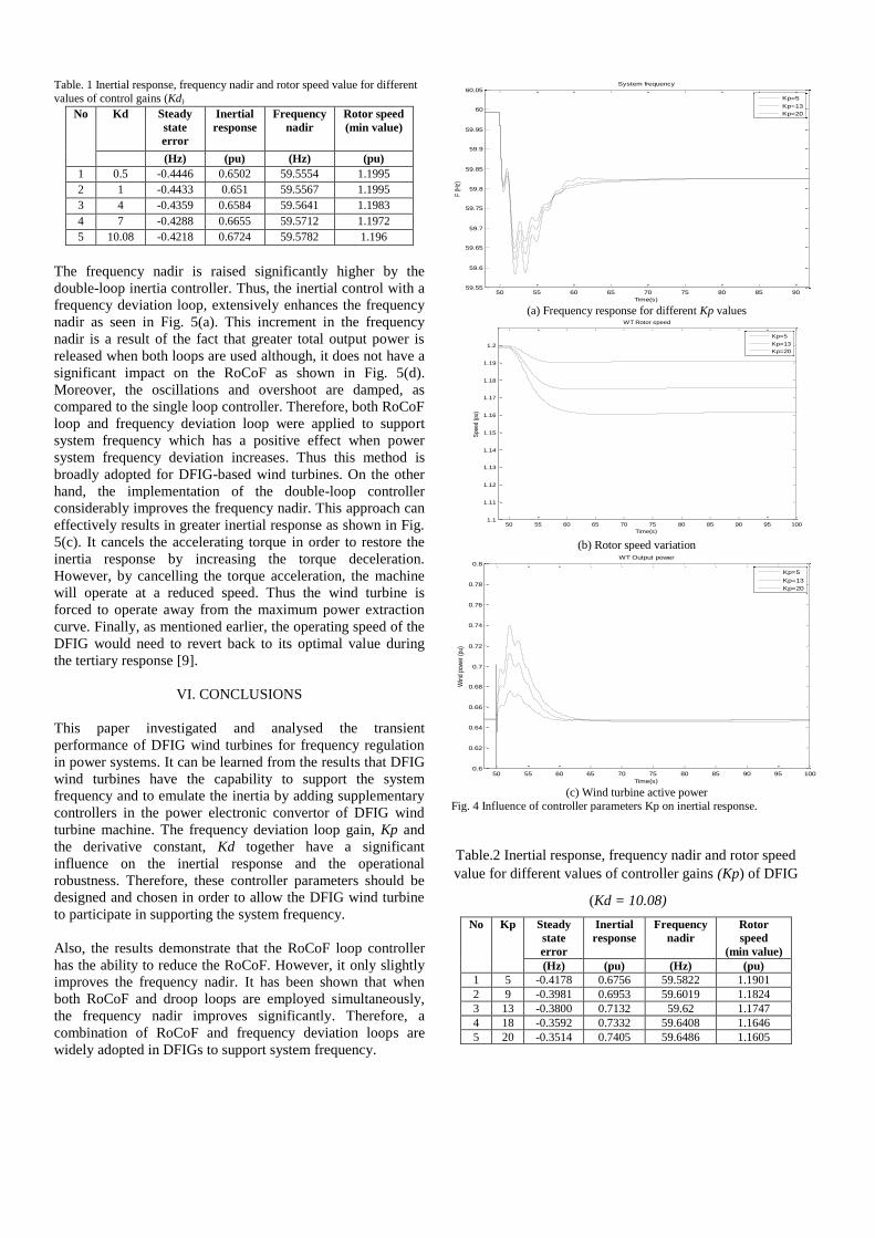
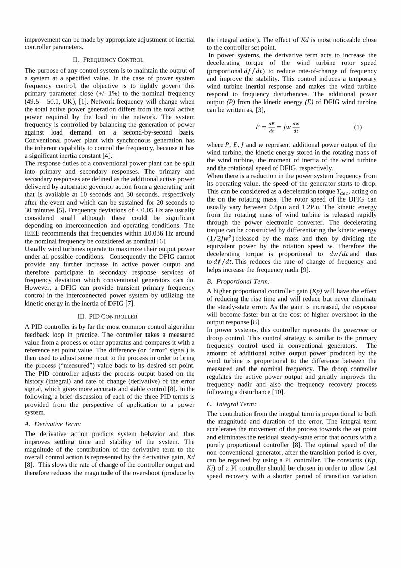
Table. 1 Inertial response, frequency nadir and rotor speed value for different
values of control gains (Kd)
No Kd Steady
state
error
Inertial
response
Frequency
nadir
Rotor speed
(min value)
(Hz) (pu) (Hz) (pu)
1 0.5 -0.4446 0.6502 59.5554 1.1995
2 1 -0.4433 0.651 59.5567 1.1995
3 4 -0.4359 0.6584 59.5641 1.1983
4 7 -0.4288 0.6655 59.5712 1.1972
5 10.08 -0.4218 0.6724 59.5782 1.196
The frequency nadir is raised significantly higher by the
double-loop inertia controller. Thus, the inertial control with a
frequency deviation loop, extensively enhances the frequency
nadir as seen in Fig. 5(a). This increment in the frequency
nadir is a result of the fact that greater total output power is
released when both loops are used although, it does not have a
significant impact on the RoCoF as shown in Fig. 5(d).
Moreover, the oscillations and overshoot are damped, as
compared to the single loop controller. Therefore, both RoCoF
loop and frequency deviation loop were applied to support
system frequency which has a positive effect when power
system frequency deviation increases. Thus this method is
broadly adopted for DFIG-based wind turbines. On the other
hand, the implementation of the double-loop controller
considerably improves the frequency nadir. This approach can
effectively results in greater inertial response as shown in Fig.
5(c). It cancels the accelerating torque in order to restore the
inertia response by increasing the torque deceleration.
However, by cancelling the torque acceleration, the machine
will operate at a reduced speed. Thus the wind turbine is
forced to operate away from the maximum power extraction
curve. Finally, as mentioned earlier, the operating speed of the
DFIG would need to revert back to its optimal value during
the tertiary response [9].
VI. CONCLUSIONS
This paper investigated and analysed the transient
performance of DFIG wind turbines for frequency regulation
in power systems. It can be learned from the results that DFIG
wind turbines have the capability to support the system
frequency and to emulate the inertia by adding supplementary
controllers in the power electronic convertor of DFIG wind
turbine machine. The frequency deviation loop gain, Kp and
the derivative constant, Kd together have a significant
influence on the inertial response and the operational
robustness. Therefore, these controller parameters should be
designed and chosen in order to allow the DFIG wind turbine
to participate in supporting the system frequency.
Also, the results demonstrate that the RoCoF loop controller
has the ability to reduce the RoCoF. However, it only slightly
improves the frequency nadir. It has been shown that when
both RoCoF and droop loops are employed simultaneously,
the frequency nadir improves significantly. Therefore, a
combination of RoCoF and frequency deviation loops are
widely adopted in DFIGs to support system frequency.
(a) Frequency response for different Kp values
(b) Rotor speed variation
(c) Wind turbine active power
Fig. 4 Influence of controller parameters Kp on inertial response.
Table.2 Inertial response, frequency nadir and rotor speed
value for different values of controller gains (Kp) of DFIG
(Kd = 10.08)
No Kp Steady
state
error
Inertial
response
Frequency
nadir
Rotor
speed
(min value)
(Hz) (pu) (Hz) (pu)
1 5 -0.4178 0.6756 59.5822 1.1901
2 9 -0.3981 0.6953 59.6019 1.1824
3 13 -0.3800 0.7132 59.62 1.1747
4 18 -0.3592 0.7332 59.6408 1.1646
5 20 -0.3514 0.7405 59.6486 1.1605
50 55 60 65 70 75 80 85 9059.55
59.6
59.65
59.7
59.75
59.8
59.85
59.9
59.95
60
60.05System frequency
Time(s)
F (
Hz)
Kp=5
Kp=13
Kp=20
50 55 60 65 70 75 80 85 90 95 1001.1
1.11
1.12
1.13
1.14
1.15
1.16
1.17
1.18
1.19
1.2
WT Rotor speed
Time(s)
Spe
ed (
pu)
Kp=5
Kp=13
Kp=20
50 55 60 65 70 75 80 85 90 95 1000.6
0.62
0.64
0.66
0.68
0.7
0.72
0.74
0.76
0.78
0.8WT Output power
Time(s)
Win
d po
wer
(pu
)
Kp=5
Kp=13
Kp=20

(a) Power system frequency
(b) Rotor speed variations
(c) DFIG active power output
ACKNOWLEDGEMENT
The first author would like to acknowledge the financial
support provided by the Department of Employment and
Learning, Northern Ireland to carry out this research.
REFERENCES [1] M.A. Hanley, "Frequency instability problems in north American
interconnections," National Energy Technology Laboratory (United States) 2011.
[2] B. Fox, Wind power integration: connection and system operational
aspects, Iet, 2007. [3] J. Ekanayake and N. Jenkins, "Comparison of the response of doubly
fed and fixed-speed induction generator wind turbines to changes in
network frequency," Energy Conversion, IEEE Transactions on, vol. 19, no. 4, pp. 800-802 2004.
(d) RoCoF
Fig. 5 Interial response of DFIG with single and double loop
[4] J. Ekanayake, L. Holdsworth and N. Jenkins, "Control of DFIG wind
turbines," Power Engineer, vol. 17, no. 1, pp. 28-32 2003 [5] Holdsworth, L., ekanayake, J. B. and jenkins, N. (2004), power system
frequency response from fixed speed and doubly fed induction
generator-based wind turbines. Wind energy. 7: 21–35. doi: 10.1002/we.105,”
[6] P. Alto, "EPRI Power System Dynamics Tutorial, Final Report," THE
ELECTRIC POWER RESEARCH INSTITUTE, INC. (EPRI), California, Rep. 1016042, July 2009 2009.
[7] I. Moore and J. Ekanayake, "Frequency response from wind turbines,"
in 2009 44th International Universities Power Engineering Conference (UPEC), 2009.
[8] W.C. Messner, D.M. Tilbury and A.P.R. Hill, Control Tutorials for
MATLAB® and Simulink®, Addison-Wesley, 1999. [9] G. Ramtharan, J.B. Ekanayake and N. Jenkins, "Frequency support
from doubly fed induction generator wind turbines," Renewable Power
Generation, IET, vol. 1, no. 1, pp. 3-9 2007. [10] M. Kayikci and J.V. Milanovic, "Dynamic contribution of DFIG-based
wind plants to system frequency disturbances," Power Systems, IEEE
Transactions on, vol. 24, no. 2, pp. 859-867 2009. [11] J.M. Mauricio, A. Marano, A. Gómez-Expósito and J.L.M. Ramos,
"Frequency regulation contribution through variable-speed wind energy conversion systems," Power Systems, IEEE Transactions on, vol. 24,
no. 1, pp. 173-180 2009.
[12] O. Dudurych and M. Conlon, "Impact of reduced system inertia as a result of higher penetration levels of wind generation," in Power
Engineering Conference (UPEC), 2014 49th International Universities,
Cluj-Napoca; Romania, 2014, pp. 1-6. [13] J. Morren, S.W.H. de Haan, W.L. Kling and J.A. Ferreira, "Wind
turbines emulating inertia and supporting primary frequency control,"
Power Systems, IEEE Transactions on, vol. 21, no. 1, pp. 433-434
2006.
[14] Z. Zhang, Y. Sun, J. Lin and G. Li, "Coordinated frequency regulation
by doubly fed induction generator-based wind power plants," IET Renewable Power Generation, vol. 6, no. 1, pp. 38-47 2012.
[15] H. Lee, J. Kim, D. Hur and Y.C. Kang, "Inertial control of a DFIG-
based wind power plant using the maximum rate of change of frequency and the frequency deviation," Journal of Electrical
Engineering and Technology, vol. 10, no. 2, pp. 496 2015.
50 55 60 65 70 75 80 85 90 95 10059.5
59.6
59.7
59.8
59.9
60
60.1System frequency
Time(s)
F(H
z)
Inertial control with one loop
Inertial control with two loops
50 55 60 65 70 75 80 85 90 95 100
1.16
1.165
1.17
1.175
1.18
1.185
1.19
1.195
1.2
1.205
WT Rotor speed
Time(s)
Speed(p
u)
Inertial control with one loop
Inertial control with two loops
50 55 60 65 70 75 80 85 90 95 100
0.58
0.6
0.62
0.64
0.66
0.68
0.7
0.72
0.74
WT Output power
Time(s)
Win
d p
ow
er(
pu)
Inertial control with one loop
Inertial control with two loops
50 55 60 65 70 75 80 85 90 95 100-12
-10
-8
-6
-4
-2
0
2
4x 10
-3
Time(s)
df/
dt
(Hz/s
)
RoCoF
RoCoF no Inertial response
RoCoF with combined controller
RoCoF with inertia controller

![Inertial Navigation Systems - Indico [Home]indico.ictp.it/event/a12180/session/23/contribution/14/material/0/... · Inertial Navigation Systems. Inertial Navigation Systems ... •](https://img.pdfslide.net/doc/110x75/5a94bdc87f8b9a451b8c1652/inertial-navigation-systems-indico-home-navigation-systems-inertial-navigation.jpg)