Embed Size (px)
Citation preview

INVESTIGATION OF MODES OF THERMAL FRACTURE
OF SOME BRITTLE MATERIALS
by
CHARLES R. NELSON
BS, University of North Dakota(1962)
.MS, Massachusetts Institute of Technology(1965)
CE, Massachusetts Institute of Technology(1967)
Submitted in partial fulfillment
of the requirements for the degree of
Doctor of Philosophy
at the
Massachusetts Institute of Technology
September 1969
Signatu"re of AuthorDepartment of Civil Engineering
Certified by
Accepted by
................... ..- .Thesis Supervisor
Chairman,Departmental Committee on Graduate Students
\

ABSTRACT
I~VESTI~ATION OF MODES OF THERMAL FRACTURE
OF SOME BRITTLE MATERIALS
by
CHARLES R. NELSON
Submitted to the De~artment of Civil Engineering on September 2, 1969, in partial fulfillment of the requirements forthe degree of Doctor of Philosophy.
An analysis of the temperatures and the thermalstresses in a detailed and accurate manner with the finiteelement technique resulted in the following advancementsin the understanding of the nature- of the thermal spallingproblem.
Thermal spalling due to local heating on the surface·of briLtle materials is the result of the comple~e propagation to total failure of a fracture induced by tensilestresses acting on a plane parallel to the surface and justunder the heated area. If the material at th15 surfacefails in compression before the tensile stress inducedfracture occurs, spal11ng is prevented. There must besufficient strain energy released by the fracture processto form the fracture surface required for complete failule.
Experiments conducted on granite, marble and porcelaincorroborate the theoretical expectations. The granite andporcelain specimens spalled at the heating time whichproduce calculated tensile stresses equal to the tensilestrength. Crushing of the surface was observed on themarble specimens as predicted from the calculated stresses.
Convex surfaces and a high ratio·of compressivestrength to tensile strength increase the likelihood thatspalling will occur in a given situation.
Thesis Supervisor: .Fred Moavenzadeh
Title: Associate Professor of Civil Engineering
2

ACKNOWLEDGMENTS
The initial part of this thesis was carried out
under partial support by the National Science Foundation
via a fellowship to the author. Later the U. S. Department
of Transport supplied the complete support. This suppo~t
1s gratefully acknowledged.
Appreciation is extended to the thesis committee
members, Professor Pian, Professor Con~or and Professor
McGarry for their interest and advice. Special appreciation
Is extended to my advisor, Professor Moavenzadeh, for his
advice, assistance, patience and encouragement over an
extended period of time.
Fellow student, George Farra provided his valuable.
aid and abilities which contributed greatly to the
suc~essful conception and execution of this thesis.
I am indebted to my children, Brent and Kimberlee,
for the opportunities and experiences we have missed and
lost forever while I was working on this thesis. Deserving
credit for perseverance is my wife, Marlys, who in addition
to cheerfully typing this manuscript, worked part time,
made financial sacrifices and did without my company.
3

TABLE OF CONTENTS
TIT LE PAGE •••••••.•••••••••••••••••••••.•.••••••••• 1
ABSTRACT •••••••••• '. • • • • • • • • • • • • • • • • • • • • • • • • • • • • • • • • 2
AC KNOWLEDGMENT ••••••••••••••••••••••••••••••••••••• 3
TABLE OF CONlfENfJ.1S •••••••••••••••••••••••••••••••••• 4
INTRODUCTIONCHAPTER ,I
1.1 General .......................... 7
1.1.1 Basic Mechanisms 8
1. 2 Obj ect1ve and Scope ••.•.••..•••.. 11
CHAPTER II THEORY
2.1 General .......................... l~
2.2. Fracture Mechanics ......••... ~ ... 14
2.2.1 Past Work on RockDestruction .......•..•...• 15
2.2.2 Related Past Work , 11
2.2.3 The Problem of.Spalllng 22
2.2.~ Initiation and Propagationof Fracture ...........•... 28
2.2.5 Failure Mechanisms forSpa11ing 39
2.3 Analysis Technique 48:t
2.3.1 General................... 48
2.3.2 Characteristics of theMaterial Properties 51
4

TABLE OF CONTENTS(Continued)
Page
2,3.3 Unusual BoundaryConditions 52
2.3.4 Sequence of Operations 53
2 . 3· 5 Heat ing Time 53
2.3.6 Numerical Methods Used 54
2.3.1 Heat Transfer Analysis Sij
2. 3. 8 Stress Analysis .•......•.. 56
2.3.9 Energy CalcUlations 57
CHAPTER III EXAMPLES
. 3.1 Purpose .......................... 58
3.2 Material Properties •..•.......... 59
3.3 Experimental Evaluation of someProperties 62
3.4 Specific Examples with Thin Disks. 63
. 3.4.1 General •....•••..•..•••... 63
3.5 Specific Examples with Cylinders. 69
3. 5 .1 Generai................... 69
3.5.2 Variation in .SpecimenLength .•••.••••••"• • • • . • • •• 72
3.5.3
3.5.4
3.5.5
•Variation in Power(Granite) .....•...........
Variation in Power(r·1ar b1e) .
Variation in Power(Porcelain) .
5
76
79
87

Page
D. List of Figures ••••..••••.•••••.. 149
101
102
152...................
......................
......................
6
Conclusions
Future Work
List. of Tables
TABLE OF CONTENTS(Continued)
A. Heat Transfer by the Finite ElementMethod ...•.•..•...••.•.•.••.•••.. 111
5. Strain Energy Calculations , 126
C. Detailed Instruction for theAnalysis Technique .•••.•••.•••••. 126
E.
CHAPTER· IV CONCLUSIONS AND FUTURE WORK
APPENDICES
BIOGRAPHY .......•.............................•••.. 109
BIBLIOGRAPHY AND REFERENCES ..............•...•••••. 107
I

-
CHAPTER I
INTRODUCTION
1.1 GENERAL
,Today an increasing amount of :~ock 1s being excavated
for construction and mining projects. New methods are
bein~ introduced to increase the excavation rates, reduce
the cost or both. Some of these methods are modifications
of older methods while others are essentially new or
novel. The design and use of the equipment for these new
methods 1s at the present difficult because of lack of
knowledge of what the requirements are'.
An exampie of a modification of an older method of
excavation is the boring or tunneling machines for large
tunnels which use rolling cutter wheels in much the same
manner as do the smaller drills that have been used for
sometime. The design and operation of these large machines
can be based, in part, on the large amount of data and
experience which has been slowly. and expensively accu
mulated from the operation of the smaller drills. However,
for many of the new methods being developed the empirical
data and experien~e are totally inadequate for proper
designing of equipment. Typical of these methods are the
use of shaped explosive ~harges, electrical heating elements
7

and combinations of older methods such as simultaneously
heating ~nd us~ng convential cutting rollers.
There lsa need to develop a rational technique for
the design and use of the excavating equipment for these
new' methods~ since the alternative to the development of
such a lational technique 1s the establishment of large
amounts of empirical data with extensive and comprehensive
full scale tests. This would be costly and time con-
Burning, whereas a rational technique should only require
a few full scale experiments to establish its validity
and range of applicability. The basis of such rational
techniques for the design and use of new equipment would.
be a quantitative understanding of the mechanisms within
the rock which result in the removal cf the material.
This would allow the engineer to design equipment to most
effectively activate those mechanisms. For example, frac
ture 1s one class of mechanisms which are Important in the
removal of rock by spalling due to rapid heating of the
surface. A detailed and accurate knowledge of the stress
field that causes this fracture would be required before
the equipment which generates the stress field could be
rationally and correctly designed.
1.1.1 B~sic Mechanisms. Most methods of excavation,
old and new, ~re based on one or more of the following
8

•
basic- mechanisms which degrade the rock to a state
that all~ws ea~y removal [1].
1. Phase Change
2. Chemical Reaction
3. Fracture
The most common method based on a phase change 1s
to employ heat to melt or vaporize the material which
will then flow away. For example, large scale use of
this 1s being made to mine sulfur. The sulfur 1s then
pumped to the surface and allowed to solidify before
further processing ..
The chemical reactions may be caused by the addi-
t10n of chemicals which will react with the rock and
result in products which can be simply and easily removed.
Also in this category are the chemical reactions which
occur due to heating the material., An example of this
1s the decomposition of calcium carbonate in marble which
results in a soft crumbly product that is easily removed.
Methods which-are based on fracture have the most
wide spread use today and are usually the most efficient
in terms of cost and energy absorbed per unit of rock
removed. This energy is dissipated within the rock during
9

fracture by plastic deformations, formation of new 5ur-
faces, h~at1ng~ shock waves, kinetic energy of chips and
others. For mechanical drilling methods it has been estab-
11shed that the energy required is approximately inversely
proportional to the final size of the removed rock [ 1 J.
Therefore, the methods which produce the largest chips
requires. the least energy input to the rock. However,
since different methods have different energy conversion
efficiencies and may use different sources of ~nergy,
the one which uses the least energy 1s not necessarily
the least expensive.
The fractures in the rock are induced by the stresses.
which exist in the material at the start of fracture.
These stresses are usually induced mechanically by apply-
lng concentrated loads at the surface, or thermally by
heating or cooling the surface. Also, of great importance
are the stresses which exist in the rock due to natural
causes which may make the fracturing process easier or
more difficult depending on thei~ pattern and magnitude.
For example, in very deep wells the high existing stresses
make the rock behave in a plastic manner which makes
fracturing more difficult. The size and shape of rock
pieces removed depends on the type of rock and the method
used.
10

The use of methods based on fracturing the rock
by thermal stresses 1s gaining wide spread acceptance
today in rocks which are exceptionally hard to drill
by convent1al methods [1]. A prime example is the
use of flame jets to drill the blast holes during the
mining of the iron ore, called taconite. The flame
jets are. also being used to channel blocks of granite,
thus eliminating blasting operations which tended to
degrade the material that 1s used for building and
monument use.
The actual mechanisms by which the flame jet removes
the rock during spalling is not understood in any detail.
[2 ], although it is usually assumed that it 1s a thermal
stress induced fracture. The rock removal rate decreases
and in some cases nearly stops in some rocks and in the
region of faults and other discontinuities. The addition
of an abrasive to the flow of hot gas increases the
removal rate in some soft rocks [2]. It is not well
understood why hard rocks usually spall best and some
rocks do not seem to spall at all.
1.2 OBJECTIVE AND SCOPE
The objective of the thesis is to develop and dem-
onstrate a practical method to study in a quantitative
manner the basic failure mechanisms of- the brittle fracture
11

type· in rock, during excavation. This will help in the
rational design of excavation equipment by eval~ating the
effect of the applied loads or heating in an analytical
manner.
The scope of the thesis is:
1. The development of' an analysis technique to eval-
uate the" temperatures and stresses induced in the rock with
sufficient detail and accuracy that the mechanisms of fail-
ure of the brittle fracture type may be investigated. It
1s capable of handling complicated boundary conditions and
nonlinear and nonisotropic material properties.
2. The comparison of results fI·om the analysis with•
experimental data to validate the analysis technique and
the assumptions which went into it.
3. The development of hypotheses about some of the
important fracture mechanisms of failure which may occur
when rock or other brittle materials are heated rapidly
on the surface. These hypotheses are sufficient, for
many cases, to predict if spalling results for a given
set of conditions. These hypotheses are based on the
material's properties and the temperatures and stresses
evaluated with the developed analysis t~chnlque.
~. The experimentation on spe~imens of marble,
granite and porcelain using a gas laser for a heat source.
12

The developed hypotheses are applied and comparisons
made between predicted and experimental resul~s.
The finite element method was used for the heat
transfer and stress analyses so that it was possible
to solve problems having irregular boundaries and
nonlinear and nonisotropic material properties. Th~
heat transfer analysis computer program evaluates
the transient temperatures throughout the body based
on the initial conditions, boundary conditions and
material properties. The stress analysis computer
program evaluates the stresses based on the tem
perature distribution, boundary conditions and material
properties. Both computer programs are limited to two
dimensions in order to minimize time.
The theory of spalling is based on the concepts or·
modern fracture mechanics: It expresses the spallability
of a material, i.e. criteria for crack initiation and
crack propagation) in terms of the material properties
and the functions evaluated with the analysis technique.
Experiments were conducted on specimens of marble,
granite and porcelain in the shapes of disks·, cylinders
and spheres. The. specimen was locally heated using a
carbon dio~ide gas laser.· The experimental data and
results were compared· with results predicted by the
analysis and theory to check and verify both.
13

I
CHAPTER II
THEORY
2.1 GENERAL
. The theoretical development in this thesis 1s dlvided
into two parts. The first is the development of hypotheses
abo~t the fracture mechanisms for thermal spalling, The
second 1s the development of analysis techniques to cal-
culate the temperatures and stresses for use in the first
part.
2.2 FRACTURE MECHANICS
To date,.most of the research into the destruction
of rock for mining or construction purposes has not
investigated the mechanisms of failure in detail. It has
instead been experimental parameter studies using full
scale; or nearly full scale equipment, or "theoretical"
studies based on assumed stress fields or overly sim-
p11fied models [3]..
The results of this work has been very valuable in
reach~ng local optimums in the design .and the operational
technique for the existing equipment. However, since
detailed accurate knowledge ~f the mechanism or mechanisms
of destruction was not available, it was difficult to apply
l~

the results o~ this type of research to other materials
or excavating equipment which were different in even
modest ways.
The mechanisms were not investigated in detail because
the stresses induced within.the material by the equipment
was not known with sufficient detail or accuracy nor were
the basic principles of rock failure well understood.
There were at least two reasons why the stresses could not
be found with the required detail and accuracy. First, the
boundary conditions that existed between the rock and the
excavating equipment were not known with the detail and
accuracy required for analysis. Second, due to the complex
boundary conditions and the nonlinear material properties,
an analysis was impossible with the classical methods.
2.2.1 Past Work on Rock Destruction. Evens and
Murrell [ 4] modeled the problem of a wedge penetrating
soft coal in a simple manner. They assumed that the
normal stress between the wedge and the coal was equal to
the unconfined compressive strength of the coal and that
the tangential stress between the wedge and the coal acted
. upward on the surface of the wedge. and was equal to the
normal stress times the coefficient of friction. This
simple model resulted in predictions which correlated well
15

with experiments conducted in soft coal but very poorly
with experiments conducted in limestone, a more brittle
rock in which chipping 1s ~mportant.
Paul and S1karskie [5] modeled the problem of a
wed~e penetrating a brittle material in which chipping
would take place. Their assumptions were that the Mohr
Coulomb criteria was satisfied along the fracture plane
at the time of chip formation, and the fracture ext~nds
1n a straight line from the tip of the wedge to the
surface of the material some uistance away from the
wedge. This model accurately predicted the shape of
the loading curve and the required penetration force
if the slope of the load-deformation curve was found
experimentally.
Several studies using the technique of photo-elastic
analysis to find the stresses have been conducted. Ones by
Garner [6] found that there existed tensile stresses
across the potential fracture plane for the case of in
dexed penetrations by a single bit-tooth. However, since
the materials used for the photo-elastic analysis have
different properties than real rock and the interaction
with the bit is hard to simulate, littl~quantitative
work has been done.
16

2.2.2 Related Past Work. Research conducted by non
mining ortentented groups has investigated the destruction
mechanisms 1n some detail. One reason they have been able
to do this is that the loading, material properties and
geometry were often more favorable to a simple, but accurate
and detailed analy~~s. An example of the experiments which
they conducted was to submerge spheres of homogeneous
material into hot fluids and observe the resulting fracture
phenomena.
In particular, people in the ceramics industry have
been interested in the phenomenon called thermal spalllng
because of the many products that must be designed to
withstand rapid heating or cooling. They have been in
terested in finding the actual mechanisms of failure so
that products of ceramic materials could be rationally
designed to withstand conditions for which it was not
practical, or economical to run experiments on pro-
totypes. At first their efforts were not successful
because a good analysis was not possible due to the complex
specimen shape used to study the problem. This lead to
erroneous conclusions as to the mechanisms responsible for
the spalling. An example of this was the work by Norton [7]
in which he incorrectly hypothesized the cause of spalling
to be a fracture induced by shear stresses which he thought
17

existed along the isothermal lines. He even derived
equations for these imaginary shear stresses, b~t they
were not valid. His experiments consisted of rapidly
heating one end of oven liner bricks and noticing loss
of material at the heated end due to spalling. (See
Figure 1). Initially for analys1~ Norton modeled the. .
problem with a half-space which was .subjected to an in-
crease in surface temperature. It was the lack of tensile
stresses for this model that lead him to misinterpret the
mechanism to be a shear stress induced fracture. Later
[ 8] he conducted a photo-elastic study of heating of
brick shaped models. However, he again erroneously•
interpreted the results to justify his shear stress
mechanism.
Norton [ 9] continued to put forth his shear stress
1ndu~ed mechanism theory in one form or another. Norton's
theory was rebutted by Preston [10], who suggested that
thermal spalling is always caused by tensile stresses wlth-
in the material. However, he was ~ot certain of the
location of the tensile stresses that started the' spalling
but indicated that the stress may be such that the crack
would start at the surface and travel into the body.
Preston also stated that the sJ~rain energy released
by the propagating crack must exceed the energy required
18

·... I •
j""'~T'<':,;~- ~".- <?~: '. :;~.~.. ~\...."'..,. ~., .. "'. '.".'"'- - " ~-; _. ,._.. ."."': ,- .-- '0. ---'- .- ~ I
t
~
\.0
.~~E SURFACE~
I .Lx
THIS END HEATED STRESSES NORMALTO THE CENTER
FIGURE I: SPALL SHAPE AND ASSOCIATED STRESSES [7]

to form the new surface area. In this respect, he se,ems
to have been the first to apply both the concept of crack
initiation and, crack propagation to the spalling problem.
Preston did not conduct any analysis or experiments to
back up this theory about the mechanisms of spal11ng.
In 1955 Kingery [11] concluded, based on the inves
tigations to that date, that the mechanism responsible
for thermal fracture was a stress induced fracture. Based
on this idea, it was possible to establish the,effect that
the values of the material properties have upon the spall
ability of a material.
Since a stress initiated fracture was the mechanism
which causes spalling, it was shown that materials with
high strength and a low modulus of elasticity would be the
most spall resistant. Also, for the case of spalling
caused by sudden surface heating, materials with a high
thermal conductivity and dlffusivity, and a low coefficient
of thermal expansion and emissivity were the most spall
resistant.
In 1963 Hasselman [12J again brought up the hypothesis
(first pointed out by Preston [10]) that the strain energy
released by the crack's formation must exceed the energy
required to create the new surface area or else the crack
will be halted and spal'ling will not occur.
20

Hasselman conducted experiment,s with specimens, of a
very brittle material, a less brittle material and a tough
material. These materials were rapidly heated to observe
their spal1~ng behavior. The brittle material shattered
when heated, the secon~ and third ~ld not break completely
apart. However, they may have" had spall fractures within
since it was calculated that the tensile stress of each
material was exceeded in the interior region of the
spheres. His calculations show that for the two tougher
materials there was not sufficient energy available for
release,during fracture, in order to create the new surface
area required to completely separate a' "chip" from the
parent material.
The conclusion to be drawn from this work is that there
exist two conditions that are necessary and sufficient to
incur a spalling type of failure: 1) The fracture ~trength
of the material must be exceeded at some point in the
specimen. 2) The releasable strain energy associated with
the projected crack formation must ~xceed the energy
required to form the new surface area created by this crack.
To minimize this available energy for a spall resist-
ant material, the. strength should be low and the modulus
of elasticity and effective surface energy should be high.
21

The effective surface energy rere~red to is the energy
required to create a unit area of new surface by the
fracture process:
Before this work by Hasselman, other efforts to find
what a material's properties should be to prevent spalling
had considered only the initiation of the cra~k. Their
observations had never included a situation in which a
crack was observed to form, but did not 'propagate a
sufficient distance to form a spall. The reasons for this
oversight were as follows: 1) The crack usually starts
in the interior of the specimen and is difficult to find
if it has not propagated to the surface. 2) Most
materials which the other people tested have properties
such that if a crack starts there is sufficient energy
available to completely propagate the crack and thus
cause spalling.
2.2.3 The Problem of Spall1ng. The phenomenon,
commonly known as spalling, occurs in many different
materials and situations. Often it· 1s desirable to control
the phenomenon for the advantage of man. Some of these
situations will be considered to gain insight into the
problem and to demonstrate that there is ~ marked
similarity between the stress fields for the various cases.
22

· First, th~ term spalling will be defined as the loss
of material from a body by a fracturing process which is
induced by the stresses existing in the. body. These
stresses may be due to mechanical loadings, temperature
changes, phase changes, changes in moisture content, etc.
While 1n most'cases the final stresses are the result of
some combination of these, 'often on~y one will predominate.
The spal11ng of fire bricks has long been a problem
in large industrial ovens. It was this problem that lead
Norton [ 7] to conduct his research in the field of
spalllng. The end of the brick which formed tile inside
surface of the oven was the location at which the spalling
occurred. This end would be exposed to rapid heating
when the oven was started inducing stresses as shown in
Figure 1.
Spalling in concrete 1s a problem in sidewalks, roads,
buildings and most other structures made from that material.
There are two locations at which the spalllng usually occurs.
The first 1s at joints which are not separated an adequate
distance or do not have an appropriate soft filler in place:
When' a joint with either of these shortcomings tends to
close due to loading, tempera.ture change 6r others, large
stresses will be locally transmftte~ across the joint as
shown in Figure 2 causing a spall to form at the edges.
23

The second place that spalling commonly takes place in
concrete is at· the surface, around a piece of porous
aggregate: If the aggregate 1s filled with water whpn
subjected to freezing temperatures, stresses are
developed as shown in Figure 2 causing the spalling of
material around the porous aggregate.
When some types of rocks and other materials are
rapidly heated at the surface, spalling occurs. This
has been observed In detail by the author while heating
materials with a gas laser. The associated temperature
anJ stress distributions are shown in Figure. 3.
Spalling'is also observed to occur in some materials
during compressive teSts. This spalling usually occurs
at a compressive stress which is approaching the compressive
strength of the materials.· A hard inhomogeneity in the
material being tested would cause a local stress dis
tribution as shown in Figur~ ~.
In each of the cases cited above there 1s great
similarity among the various stress fields associated with
each of the spalling regions. In all cases, there extst
high compressive stresses near the surface and parallel~
to it. Also, in each case there were tensile stresses
acting on a plane parallel to and at a small distance
below the surface.
24

"J - ••J ILl 1 1111_AIIJftfl_~L.~;;;~~:~···~ ~,
:.<~
~- 0 .-_. .."", l' . ~
EXPANDING .AGGREGATE
: 0 ,,~. 0, ~'. 'e:0 -, : -b- · , 4• .' - I· '.. 0 -' • ,-
'. .' A'.· · -. •. 0 '. -0•• "_ V • 0 '. • • ,
, 'Ii '. '. : o. · · ,0 · 'D 'p', . , ~, ' 'po' - · -.. , :• .''''.' 0 • OJ I • ", ;
• I • a.··. 'I ~t:'·.6·
"I): · · '0'0· 0
, • • .. • ~,................ W'
POTENTIAL·
• SPALLINGCONDITIONS ~
f'..>\Jl '.~' . ' ,. _() ';, . Q • . - f"~
, '0- · ". • ", .-'I I - , 0 I • .,, · c.'o ~ -(). e I r.
I •
, I 0 "' · · ·I • •••• ~ ••••. .. .o"e ••
- : -=- · . '.0
aACIING
STRESSES
..• C>"•.. 0 .. 0 I··t~. · · .' '. (J
'_0.'0 '(J'• .' .' : I .' .- •• D'. -. '
· .' O· 0 ".t:i eo • •
• • •• • tI/I • •. " . ,;
'0 · '"· '.'0 'a'. .. .
JOINT IN CONCRETE
II
EXPANDING AGGREGATE
FIGURE 2= POTENTIAL SPALLING CONDITIONS IN CONCRETE

. II . II OJ JI .1."f"~1i)!tv:t~:'~;·. ,:, ',' !''-I'*1
-~;
_ .. 1 •.'--'
•
(COMPRESSION)
~4- LASE~ RADIATION
T1\.) 1-5"
0'\ i l"-../9
I -----~< ~~1'511~
ENLARGEDSECTION <l
FIGURE :3: THERMAL STRESS DISTRIBUTIO\I FROM LASER RADIATION

27
-
bm~enfflH:~8
.e
~;.~
I~-z:::>-'<tZ.-~0Z••
zV
0W
b§
b0::
0:::>
~C
)-
0LL
a::~

The material for each case was brittle in nature
from which little or no yielding could be expected.
2.2.~ Initiation and Propagation of Fractures. The
study of the failure modes or brittle materials with
consideration given to initial flaws was first considered
by Griffith [13]. He was considering the problem of the
tensile strength of glass being much lower than theoret-
ically expected. He postulated that there were initially
very small natural cracks existing in the glass which
produced stress concentrations at their tips, thus
causing the critical crack to propagate. This resulted
in total failure at a nominal tensile ·stress, much lowerI
than theoretically expected.
When the crack propagated, ene~gy was absorbed by
the process which formed the new fracture surfaces.
Griffith attributed this surface energy to the rupturing
of the bonds between the atoms on each ,side of the
fracture. For most materials, other than the most brittle,
such as glass, it has since been fo~nd [14J .that a
significant amount of the apparent effective surface en~rgy
is absorbed in plastic flow and formation of branch cracks.
In addition, if t~e fracture propagates at high speed,
energy is lost in the production of sonic waves [14].
28

-
The energy required to create the fracture surface is
found exp~rime~tally in simple experiments in which the
propagation-rate 'can be controlled and the total energy
input measured. This total energy is divided by the total
new' surface area formed to arrive at a figure called the
effective specific surface energy, l~
The source of the energy for the propagation is
conveniently divided into the strain energy released by
fracture and the energy added during propagation from
sources outside the body. Griffith initially considered
only the released strain energy.
Based on the assumption that the crack was penny-
shaped, Griffith derived the following equation of the
nominal uniaxial strength of a brittle material 1n terms
of the crack width and the effective surface energy_ It
neglects outside sources of energy.
2
a = n y E / 2 c (l-~ )f
Of The nominal uniaxial tensile strength normal to the
crack.
c The radius of the penny shaped crack.
E,~ - Modulus and Passion's ratio.
y Effect~ve surface' enery per up.i t of area.
29

30
propagate.
if ~1o=01 + a. f
For the simple case of uniaxial tension normal to
2
(Oi- o~) - BOf (01+ 02) = 0 if 01+ 302 > 0
For fractures caused by more complex two-dimensional
been derived [3]. For shear fracture it is:
with the crack was added to the energy consumed by crack
growth, and the sum was differentiated with respect to
Extension·rracture:
the following manner: First, the strain energy associated
crack growth equals that absorbed in formation of new
this is saying that when the strain energy released by
the crack length C, and set equal to zero. Physically,
°1 and O 2 are the principal stresses (compression Positive)
and 0 is the uniaxial tensile strength. They are shownf
graphically in Figure 5.
fracture surfaces, the crack will be unstable and
the crack, the resulting fracture is referred to as an
stress disturbances, the following .failure criterion has
surfaces parallel to each other during propagation.
This equation was derived using energy considerations in
extension fracture. Another, called shear fracture,
.occurs when there exist stresses which slide the two

n U•••BLlliJdiaa_
.. , ...._•• ~ _~ __ • . ..., • ~=-:.i '.-~ ~:--':";-"':-l-~.a.-....;I... ~;..., ~l'~."·:-: ....~.!!t~":"~f~~~·~~~~~:*~~:tiJ;..~~~")',~!,:-·",,-~1P'~~\~;l ...:~ ..C.Jr,:~~....~ ~ ._'~:.I t- ~~•.• ~ ~
0'2
OJ ,. a2 - PRINCIPLE STRESSES
T - UNIAXIAL TENSILE STRENGTH-
Wf-J
RANGE OF I RANGE OF•• IF EXTENSION ... SHEAR ----
FAILURES FAILURES
FRICTION ACROSS CLOSEDCRACKS CONSIDERED
T
T
3T
-,-...---Oi
FIGURE 5: BRITTLE FRACTURE CRITERION IN TWO DIMENSIONS [ 3 ]

32

W-JQ..
~U52- r--,
to
.-..........
••CDW0::::)t')[i:
33

r
This is the same as the condition for the two-dimensional
case.
°3 + a = af
°3 = minimum principal stress (max-
imum tension)
or = uniaxial tensile strength
To date, consideration of the fracture process has
been confined to the case of homogeneous stress fields.
Since most problems encountered in reality have non
homogeneous stress fields, they must be considered in the
study of fracture failures. The influence of the
nonhomogeneous stress on the initiation of the fracture
would be negligible for many cases because the initial
flaws are usually very small and the stresses would
change very slowly with respect to the flaw length. Thus,
the initiation' would occur under conditions similar to
the case of a homogeneous stress distribution. However,
the fracture may propagate over a aistance in which the
stresses vary in a substantial manner. The direction
and distance the fracture travels must be known in order
to accurately predict such types of complete failure as
spalling.
The direction that the fracture takes will be dependent
34

on the instar.taneous stresses at the moving tip. The~e
will be ~ function of the initial stresses,. additional
loading since crack initiation and the changes in stresses
brought about by the fracture. The fracture will
propagate in the direction of the line on which the maximum
tensile stress acts at the tip. For many cases, the
knowledge of the prefracture (initial) stresses and the
initial fracture path will allow a very good qualitative
estimate of the direction of further propagation. If
this is not possi~leJ a detailed analysis must be used
to evaluate the new stress distribution with due regard
given the new boundary conditions. Experimental observa-.tions of the exact path of fracture should be done
Wherever possible.
Once the expected direction of the fracture is known,
it must be established if there is sufficient energy to
drive the crack the fUll distance causing the failure
anticipated. This evaluation must be quantitative in
nature and ideally would be made i~ the following manner:
The rate that at which energy is made available as a
function of fracture propagation would be calculated and
compared with that energy required for c~eation of the
new r~acture area. ·If the available energy exceeded that
required, the propag~tion would continue. The energy
35

avai~able for further propagation would be that released
by such propagation, and any energy left over from earlier
propagation which was not used in creating new fracture
area or lost by wave motion to distant parts of the body.
This excess energy would be stored locally in the form
of kinetic energy and would be lost if the speed of
propagation was not continuous and rapid.
To state the problem more formally, consider G as
the energy made available by a unit area increase in
fracture surface. Much of this energy G is made
available by the release of strain energy from the
reduction in stresses due to the fracture. if it is
an extension type fracture which penetrates into a
zone where compressive stresses are acting across the
fracture then G will be negative. Following this,
consider additional notation for other relevant
parameters: y is the energy consumed to ·create a
unit of fracture area; TG is the total energy made
available if the fracture propagates to completion; Ty
is the total energy required to form the new fracture
surface; LG is energy lost during the creation of a
unit of fracture area and TLG is the total lost during
the creation of the whole fractu~e. A is the totalo
new fracture area formed during propagation to complete
36

is A is:
y dA
LO dA
G da
G dA - JY dA - J LG dA
A A
Ao
I
=
=
TLG =
Ty
TG
NG =
NG = f (G - Y - LG) dA
A
If NG is positive for all values of A. it can be
failure. The relations between these quanities are:
The NO net energy at a given time when the fracture area
expected that the fracture will propagate. to completion.. "
If NG > 0 for all A from 0 to A completeo
propagation occurs.
31

fracture area is:
38
The second relation which can be established is the
at initiation
Y - LG > 0 for any point
G - y - LO ~ a
tf NG = 0 and G
The evaluation of these energy relations for the entire
The prev~ous relation implies an excess of energy
The total energy made available is found by evaluating
Ty = J Y dA
Ao
points. Expressed mathematically, this is to say that
would continue if the available energy was zero at discrete
available at all times. It is also true that propagation
and NG > 0 for all other point~
then complete crack propagation will occur.
the new area:
the scope of present analysis techniques. For most cases
fracture area for most practical problems would be beyond
there would only be two relations known in a quantitative
manner. The first is at initiation where the rate of
available energy equals or exceeds that required to form
total energy absorbed in fracture work and the total made
available. The total energy absorbed in creating new
-

~ ,
39
TG < Ty + TLG complete fracture is impossible
For most2.2.5 Failure Mechanisms for Spalling.
propagation to complete failure.
only two quantitative relations can be established. These
are the last two equations in Section 2.2.4. One is the
TG > Ty + TLG necessary' (not sufficient) to
A necessary, but not sufficient, condition for complete
and TLG 1s the total energy lost o~tside the system during
TO = PE initial - PE final + IE
practical problems with nonhomogeneous st~ess distributions,
where TG 1s the total energy made a~ailableJ Ty 1s the
total energy used in creating new fracture surface area
complete fracture
the new fracture surface for complete failure.
exceed that which is lost plus that which 1s used to form
terms. The total energy made available must equal or
fracture may then be established between the final energy
during the fracture propagation process.
where PE 1s the potential energy and IR is the energy input
potentia~ ene~gy and then adding any energy input to the
system during prbpagation:
the initial potential energy, subtracting the final
-

the uniaxial tensile strength of that material. If the
fracture is initiated in a plane approximately parallel
There are several possible types of fracture which
This stress distributionthe manner shown in Figure 1.
bottom of the chip. (See Figure 8 )
dirpction, with a slight preference to approach the surface
on account of "the bending stresses ·being tensile on the
will cause further propagation in the same general
The energy requi~ed to drive tre fracture would come
to the surface, the stress distribution will change in
acting in the zone behind the hot spot will initiate an
extension type of fracture in the material if they excee~
Considering the thermal stresses in Figure 3 , which were
due to local heating with a laser, the tensile stresses
completed fracture must run under and up to the surface.
requirements of spalling are that the fracture completely
sepa~ate materials from the ~ain body. To do this the
may initiate potential spalling situations. Of these,
only one leads directly to the formation of a spall. The
itative information about fracture direction, must be used
in hypotheses about overall failure rne.chanlsms.
ener~y·balance. at fracture initiation and the other 1s the
overall energy balance. These, together with the qual-
'I:·,f"~ r •
;
I

~~~~~1:,:;ij"·-it
~ RADIANT HEAT
.....
I
ENLARGEDSECTION
r::::::::a"-... FRACTURE
~
~
t. ,
FIGURE 7: STRESSES AFTER FRACTURE INITIATION
DURING THERMAL SPALLING

'M £ ? U If _
. . ... ."
~
ru
.THE STRESS DISTRIBUTION SHOWN IN
THIS FIGURE IS NOMINAL.
THE ACTUAL TENSION AT THE TIP
OF THE FRACTURE WILL BE MUCH
GREATER THAN SHOWN DUE ro THECONCENTRATION FAClOR.
~p OF FRJCTURE ~Ji+-TENSION•
I
t"
FIGURE ·8: NOMINAL, STRESS DISTRIBUTION
NEAR TIP'OF FRACTURE

from the release of stored elastic strain energy and
further heating during the fracture process. If the
releasable elastic strain energy 1s initially sufficient
for complete formation of the spall, the propagation
will be at such speed that the energy contributed by
further heating would be negligible.*
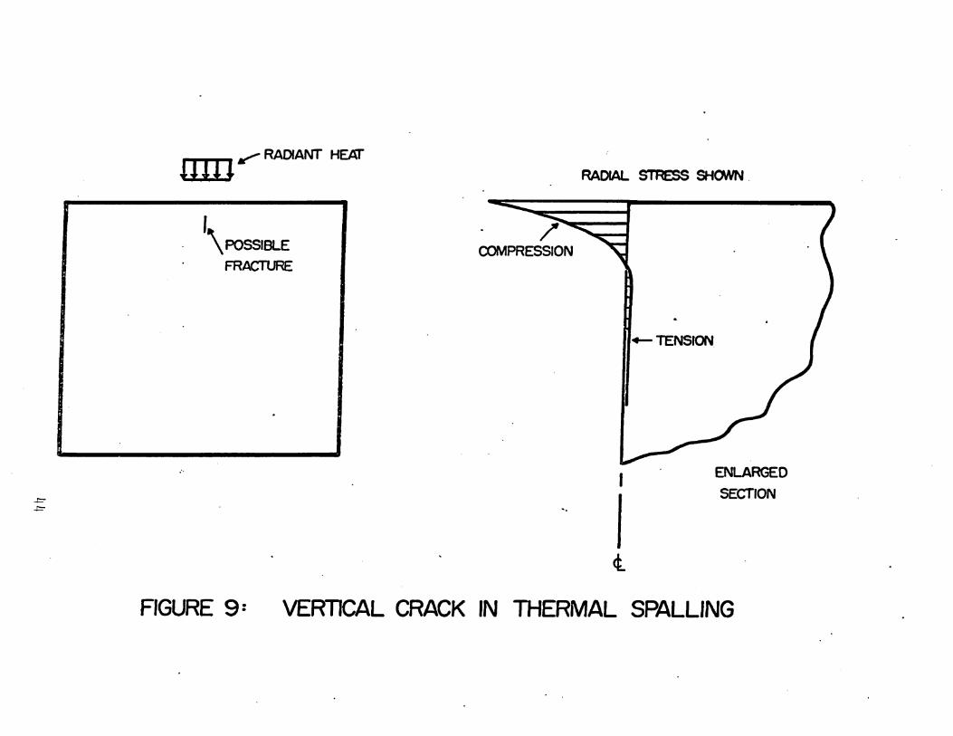
If the fracture had initiated in a v~rtlcal direction,
propagation would cease upon entering the compressive zone
above or the large very slightly 'stressed zone below. (See
Figure 9 )', Such vertical fracture does not significantly
reduce the tensile stresses acting on the planes parallel
to the surface.
Fracture may also be initiated at the surface where
the compressive stresses are the greatest. (See FigurelO).
A failure of this type would tend to reduce the tensile"
stresses underlying the compressed zone. It 1s thus.
possible and probable that there would never be a tensile
failure and hence spalling would never occur .
. For the thermal stress problem, a compressive failure
at the surface would increase the porosity of the surface
* The released strain energy, greatly in;excess of thatrequired, is converted into kineti~ energy which resultsin faster propagation.
~3
+-TENSION.
.am~ RADIANT HEAT
,\ POSSIBLE
FRACTURE
/'COMPRESSION
RADIAL STRESS SI-IONN .
~
I ENLARGED
.!=:" .... ISECTION
<l
FIGURE 9: VERTICAL CRACK IN THERMAL SPALLING

..t=Vl
.mn""'- RADIANT HEAT
--..--
'CRUSHED ZONE ~
. COMPRESSION
RADIAL srRESS SHOWN
",
I
1--~ .
¢..
ENLARGEDSECTION
FIGURE· fO: FAILURE OF SURFACE

material, which would decrease the thermal conductivity,
resulting in less heat penetrating into the intact zone.
This would reduce the existing stresses, preventing
spalling from ever occuring. Accompanying the crushing
would be possible melting at the surface by the large
amount of·heat being retained there. This melting would
result in loss of the heat energy in fusion, and in
radiation, conduction and convection to the surrounding
medium.
The circumferential tensile stresses surrounding
the hot spot could initiate a fracture which then
might propagate down into the body and" ~ideways into
slightly stressed zones next to the hot spot, and
finally into the hot spot which is in compression. Thus
this crack would not cause spalling.
The initial lack of ,energy to completely propagate
a fracture may be overcome by additional loading or
heating. There 1s at least one important potential
application of this concept of increased loading to cause
complete propagation, i.e. failure. This is in heat
assisted mechanical destruction, where the mat~rial is
heated before being subjected to mechanical loads. If the
heating injtiates the fracture, the mechanical loading may
complete the propagatiori, or if the sharp bit or the
46

mech~nical tool initiates the fracture, the heating with
its large areas of highly stressed material may supply
the energy needed to propagate the fracture.
Materials which are not completely brittle, but
undergo scme plastic deformation before fracture occurs,
will require complex analysis for the stress state at
time of fracture initiation. The evaluation' of the
available energy will also require careful consid~ration
due to the nonlinear nature of the problem.
Detailed consideration of the stress that causes
the fracture initiation and the energy for the prop
agation will be given to specific problems o'r thermal
spalling in Chapter III.
~7

2.3 THE ANALYSIS TECHNIQUE
2.3.1 General. The analysis technique was developed
to evaluate· with- sufficient accuracy and detail the func-
t10ns necessary for predictions of the spalling behavior
of'rock and other brittle materials. It has a large degree
of flexibility and generality so that solutions can be
found for complex problems having both thermal and mechan-
1eal loads, irregular boundar~ shapes and conditions and
nonlinear material properties.
Spal11ng is caused by stress induced brittle fracture
1n the material. Under the conditions and range of
stresses which spalling takes place the material properties.
are not stress dependent. The materials in which spalling
1s a problem are ceramics, the harder rocks and concrete.
The spalling occurs at a surface which is subjected to
low (usually one atmosphere) pressure with high local
stresses due to' mechanical or thermal surface loads causing
the initial failure by tensile fracture. Up to the point
of tensile fracture, the behavior of these materials is
known to be nearly·linear and elastic [ 3].
These same materials if loaded to failure' in simple
compression or in triaxial loading can, and usually do,
have large nonlinearities in the stress-strain relation-
ships. However, when the stresses in the body are such
48

that crushing or flow takes place before a tensile fracture,
the tensile stresses are relieved and spalling does not
occur. For these reasons linear stress analysis will
suffice for the prediction of spalling behavior.
The material properties will change with the tem-
peratures which accompany thermal spalllng. The non
linearity of the coefficient. of thermal conductivity
affects the analysis of thermal stresses more than any
of the other properties. In general, the conductivity
of oxides, such as most rocks, decreases substantially
with increases 1n temperature to the level needed to
cause thermal spalling. The material which becomes the
hottest is at-the surface where the heat is applied and
a great deerease in the conductivity at the surface
prevents the heat from penetrating into the body. This·
heat retained at the surface furtber raises the tem-
perature of this thin layer and causes additional decreases
in the conductivity. Th~s problem is further compounded
if the surface material fails in compressiorl increasing.the porosity which further decreases the conductivity at
the surface.
It 1s recogn~zed that while it 1s pos~ible to predict
the thermal spalling behavior for simple cases based on
linear behavior for most. properties, there exist a large
49

class of problems in which it is necessary to 'consider
more nonlinear "behavior. Practical problems of this
nature are combined heating and mechanical disin-
tegration of rock, slow fatigue type fracture in a heat
cycling environment and others. Since the investigation
of these and similar problems is envisioned in the future,
it was desirable to develop the analysis technique as
gener~l as possible. This required that the method have
room for growth to the more complex cases while taking
advantage of past developments which have been proven
accurate by comparisons with experimental data. To meet
these require~ents, numerical methods of analyses for
both the temperatures and stresses were used.
The method of analysis developed for this thesis is
not in itself unique (although the heat transfer program
was developed independently before it was available in
the literature) but the solution of thermal stress prob-
lerns with the complex boundary conditions has not been
confirmed with laboratory experiments as is done in this
work.
The thermo-elastic coupling is ·assumed to be of'f
lmp?r~ance only as the temperatures affect the stresses
and not the reverse. The stress levels encountered in
rocks near a 'free surface are sufficiently low for conven-
tial sources of heating and mechanical loads that the
5.0

assumption is reasonable. This may not be the case if
blasting .with convential or nuclear explosives is used
in disinteg~atln~ rock or for fracturing materials with
very intense sources of heat such as a laser in the
pulsed mode.
The inertia forces were neglected in the analysis.
Again this is reasonable 'in light of the conventional heat
sources and· for a large category of the mechanical equip
ment used in rock disintegration. However, there is a
significant number of rock disintegration methods in
which the inertia forces play an important role.
Examples of these are blasting, percussion drilling,
some erosion methods and others. The basic numerical
technique used could be modified in the future to eval
uate dynamic problems w~th a useful carry-over of know
ledge generated herein on the static problem.
2.3.2 Characteristics of the Material Properties.
The characteristics of the material properties include the
usual stress related nonlinearities ~aused by yielding and
crushing and in addition, those due to temperature var
iations. Also, many rocks of sedim~ntary origin display
a great deal of anisotropy in their materials. Some of
the changes in the properties are brought about by the
temperature .. However, those brought about by phase changes
51

are abrupt in nature and multivalued functions of the
temperature.
The developed analysis technique has the capability
to handle these nonlinear and anisotropic properties, but
only the nonlinear thermal conductivity was considered
for the examples analyzed .
. 2.3.3 Unusual Boundary Conditions. There are two
unusual boundary conditions which will have to be consid
ered 'for practical thermal spalling conditions and the
numerical analyses developed can simply be extended to
each. One is radiation away from a boundary with a
changing temperature and the other 1s moving boundaries.
The radiation problem is of importance for evaluation
of the net heat transfer to the heated obj~ct when radiant
heat sources are used. The relative heat t~ansfer by
radiation between two bodies is not linear with respect
to temperature, but is proportional to the difference
of their surface temperatures to the fourth power. It was
not needed for the examples in this thesis where heating
was done with a gas laser becuase the radiant heat away
from the specimen was negligible compared to the laser's
input of heat.
The moving heat source or surface must be given
consideration, respectively, in evaluating the use of
52

equipment for continuous spalling where the surface will
recede 1n.dlscr~te jumps a distance equal to the thickness
of the spall", or for equipment which moves the heat sources
over the working surface.
2.3.4 Sequence of Operations. The analysis technique
consists of a series of separate calculations of the
different functions which' control the precess under consid-
eration. The appropriate sequence of the calculations to
determine the ~hermal spalling behavior 1s as follows:
1) Calculation of the temperature distribution based on
the initial conditions and the proper boundary conditions.
2) Calculation of the stress distribution based on the
proper boundary conditions and temperature distribution
calculated in the first part. 3) These calculated temp
eratures and stresses are compared with the values required
for failure of the material to see if failure has occurred,
and if so, what type it is. 4) If part three indicates
that an extension fracture is initiated in the proper
location and headed in the proper di~ection, a calculation
is made of the strain energy available to drive the frac
ture and a prediction is made of whether or not the frac
ture wjll propagate to form a spall.
2.3.5 Heating Time. In thermal spalling environments
the temperature distribution is continuously changing with
53

time due to the application of heat at the surface and its
transfer .to the more remote regions of the body which
results 1n ~onti~uous variation of the magnitude and
distribution of the thermal stresses. It 1s necessary to
find the magnitude and distribution of the stresses at the
time they initiate the failure. To do so requires that the
stresses be computed for 'time intervals surficiently small
such that the first failure mode is correctly evaluated.
2.3.6 Numerical Methods. To achieve the required
flexibility anq generality, a numerical approach called
the finite element method [18] was used for both the heat
transfer analysis and the stress analysis. With this
numerical method, the body is modeled as an aggregate of
many small, but finite size regions within which assump
tions are made "about the behavior of the function. Based
on these assumptions) equ~t1ons are formed which relate
the ~unct1on at discrete points throughout the body. The
solution of these equations together with the assumptions
within each element define the value. of the function at
all points 1n the body.
2.3.7 Heat "Transfer Analysis. For the heat transfer
analysis) the temperature 1s assumed to undergo a linear
variation with respect to the space coordinates within each
element. The. temperature of the nodes (corners) of the
54

elements are related to each other by equations based on
the conservation of energy. These equations ar~ solved
for the nodal temperatures. The element size must be
chosen small enough such that the assumed linear variation
of temperature within each element 1s a good approximation
to the true temperature distribution.
There are two methods of solution to obtain the
transient temperature distribution. One is to use modal
analysis [19] in which the solution 1s found by super-
imposing the contribution of each of the modes which
significantly contributes to a particular solution. The
other method 1s to march the solution forward by small,
time increments based on known values of the temperatures.
The second method was used because it is more flexible
with regard to nonlinear material properties and changing
boundary shape. The complete formulation or the heat
transfer analysis technique and a listing of the computer
program 1s given in Appendix A and Appendix B.
As developed, the method can solve problems which
have.the following characteristics for the transient
temperature distributions.
1) No more than two-dimensional (plane or axi
symmetric).
55

2) The material properties may change only at the
boundary between elements.
3) The conductivity may be different in the two
directions (x, y).
4) The boundary conditions may be
A) Adiabatic
B) Given Heat Flux
C) Radiation
D) Given Temperature
E) Conduction to a Fluid of Given Temperature
5) The boundaries must be at a finite distance.
2.3.6 Stress Analysis. To evaluate the stresses,
a finite element program was used which was developed by
others [20]. This program would analyze the stresses
for problems which have the following characteristics:
1) Plane strain, plane stress or axi-symmetric~
2~ The modulus of elasticity may be a function of
the stresses all other properties are constant.
3) The material properties may· be different in
~ directions parallel to the three axis.
4) Both the temperature distribution for initial
stress free condition and the final conditions
are known.
5) The boundaries must be finite.
56

6) The condition allowed at the boundaries are:
A) Free or fixed 1n any of the directions
parallel to the axis.
B) Applied Stresses
2.3.9 Energy Calculations. As stated in Section 2.2.4
the energy which 1s available to drive the fracture 1s the
result of the release of stored strain energy and that
added by further loading or heating. For thermal spal11ng
it is observed experimentally that the fracture process
occurs at such a rapid rate that the additional heating 1s
negligible compared to the heating which precedes the
initiation of fracture~ To obtain the ·total energy made
available for 'fracture, it is necessary to calculate the
total strain energy before and after spalling and subtract
to get the strain energy released.
However, for'spalling which is caused by sudden heating
of the surface, it is possible to make approximations which
are sufficiently accurat~ for the purposes intended. This
1s done in Appendix B.
57
. , I
L

CHAPTER III
EXAMPLES
3.1 PURPOSE
Specific examples were.studied both experimentally
and analytically in order to achieve the following:
1) Demonstrate the validity a~d accuracy of the
analysis technique used to predict the thermo-elastic
response of brittle materials, and evaluate the estimates
of material properties and boundary conditions. This was
achieved by lasing thin disks in an axi-symmetric fashion,
observing the temperatures and strains, and then comparing
these with the analytical results.
2) Investigate and study the spal11ng phenomenon .
in brittle materials subjected to rapid local heating on
the surface. This was similarly achieved by axi
symmetrically lasing cylinders of natural rock (such as
granite and marble) and spheres of man-made brittle
materials (such as porcelain).
3) Test the validity of the theory developed which
explains and predicts spalling in brittle materials. This
was done by obtaining the calculated stre~6es 'as a function
of lasing time from the analysis te~hnique, and by knowing
the ~trength characteristics of the material involved)one
58

-
coul~ rind the, time and location at which the predicted
stress condition overcomes the strength of that material.'
Several experiments would then be performed which involved
lasing three-dimensional specimens. The time and location
of failure initiation was observed and compared to the
theoretical predictions.
3.2 MATERIAL PROPERTIES
The material properties required for the analysis
technique and prediction of the spalling behavior were:
1) Thermal Conductivity
2) Specific Heat
3) Density
. '4·) Modulus of Elasticity
5) Poisson's Ratio
6) Coefficient of Thermal Expansion
7) Tensile and Compressive Strengths
8) Specific Surface Energy
The experimental evaluation of some of these properties
was beyond the scope of this work an~ estimates were made
based on pUblished data for the same or similar material.
To establish confidence in the results of analyses based
I In addition to this the energy available for thepropagation of the fracture wa~ evaluated, and takeninto consideration.
I.
59

on some estimated data, comparisons were made between
analytical and experimental results in certain exper-
iments. Since the results compared well, the analysis
program was used with confidence to solve other problems
having the same materials and heat source for ranges of
temperatures and stresses that were similar to the
control experiment.'
The following material properties were evaluated
for the granite and marble used in the experiments:
1) Modulus of Elasticity
2) Tensile and Compressive Strengths
3) Coefficient of Thermal Expans.ion
For the porcelain, only the tensile strength was
evaluated. The specific surface energy has already been
experimentally evaluated for the granite and marble [16J.
These rocks were from the same quarries as those used in
the experiments conducted herein.
All other material properties were" taken from hand-
books and other published data. Table 1 lists the value
of each property and the source of information.
I If the analytical and experimental results had notcompared well, a more detailed evaluation 6f the individual properties and boundary conditions would have beenrequired.
60

MATERIAL PROPERTIES
SYMBOL DEFINITION MARBLE GRANITE PORCELAIN
Specific heat capacity 0.42 .21 .21(BTU/lb of)
K Thermal conductivity 1 12.35 X 10⁻⁵(BTU/in. sec. OF) 24ooo.+30T 31500+21.6T
p Density (lbs/in3 ) .097 ~~] .094 Ibs .094 Ibsin3 1n3
Linear coefr1cient or * •expansion (1°C) 1.22 X 10⁻⁵ 0.72 X 10⁻⁵ .50 X 10-5
E Modulus or elasticity 8.3 X 106 * 2. 4 X 10⁶ ' * 6.0 X 10⁶(psi)
Poisson's ratio 0.3 0.1 0.3
ST Breaking tensile1960 * 1560 • *stress (psi) 8,500
Sc Breaking compressive * 34000 *stress (psi) 9100 70,000
y Specific 5ur.face 50,000 50,000 2,000energy (ergs/cm2 )
0"\~ * Denotes those propertlesfound by experiment. The source of the
other data was the literature [17], [llJ ror the natural rockand porcelain, respectively.
TABLE 1

3.3 . EXPERIME~TAL EVALUATION OF SOME MATERIAL PROPERTIES
The modulus of elasticity was experimentally evaluated
for granite and marble by placing·electric strain gages
on the top and bottom of beams one inch wide by one inch
deep by twelve inches long .. The beams were loaded at their
quarter points and the strain gage readings recorded. From
this information and simple beam th~ory· for 'the stresses,
the modulus of elasticity was calculated. To evaluate this
property at much higher compressive stresses, the beams
were loaded in axial compression and the strain was
recorded. The average values of the two tests was used
in the analyses.
The tensile strength was ~xperimentally evaluated by
center· point loading of beams one inch wide by one inch
deep by five inches long~ The value of tensile strength
given by such bending tests is usually about twice that
for a uniaxial test [ 3] and this must be taken into
consideration in using the data.
The compressive strength was experimentally evaluated
by axially loading to failure four inch long prism~ with
one inch by one inch square cross-sections.
The coefficient of thermal expansion was found by
measuring the change in length of a 12 inch beam of the
material when it was heated from the freezing point to the
62

boiling point of water. The coefficient calculated from
this range of temperatures was used for a much broader
range of temperatures in analyzing the experiments done
with the laser heat source. This extrapolation is
reasonable since the materi~l does not undergo a phase
change in the· higher temperature of the laser experiments.
The tensile strength of the po~celain balls was
found by applying a compressive load to the ball through".
steel platens.* This loading condition was then analyzed
for the maximum tensile stress in the ball at the time
of failure using the finite element stress ~nalysis program.
The maximum tensile stress is in the interior or the body
as it is for the thermal spalling tests. The size and
shape of the tensile zone is also much the same as for the
thermal spalling condition. For these reasons, the ten-
sile strength found by this method seems particularly
valid to use in the prediction of the spalling response
of the porcelain.
3.4 SPECIFIC EXAMPLES WITH THIN DISKS
3.~.1 General. The analysis technique and the
assumptions or estimates about the. material properties
* This is similar to the Brazilian test for splitting·cylinders.
63


Each of the properties were taken from published
data on ~ater1al which was similar to that used in these
experiments'. The boundary conditions were approximations
based on the known total output of the laser and judgment
of the amount of heat lost from the rock. The amount of
heat lost was considered to be negligible since the tests
are of short durat:t.nn and the rock remains relatively
cool over most of its surface. The cool surface would·'.
not lose much heat by either convection to the air or
by radiation. The fraction of ra~iation energy (of 10.6
micron wavelength) from the carbon dioxide laser, which
the surface would receive, was assumed to be unity. In
all cases, the surface of the rock where the laser was
focused was covered with temperature sensitive paint.'
The analysis of the thermal strains required the use
of the coefficient of the~mal expansi.on and Poisson' 5
ratio in addition to those required for the, temperature
analysis. The coeffic1e~t of thermal expansion was exper-
imentally evaluated over the zero to. one hundred degrees
I "The paint used was "Detectotemp" brand made 'by HardmanInc., Belleville, New Jersey. The painted area at whichthe laser radiation struck the surface would almostimmediately turn black. (This was the color correspondingto the highest temperature indicating capability of thepaint.)
65

centigrade temperature range for samples of rock from
the same .sourc~ as the rock used in the other exper
iments. The value obtained in this manner was used for
the laser heating experiments in which the temperatures
are, in general, in excess of one hundred degrees cen
tigrade. Poisson's ratio was experimentally found for
the rock used in the experiments. The range of stresses
used in the.evaluation experiments was about the same
as that encountered in the laser heating experiments.
The application or the analyc~s technique in the
prediction of failure modes involves finding the stresses.
To do this only the modulus of elasticity 1s needed in
addition to those factors which are included in the
analysis or the strains. Since the modulus of elasticity
was found experimentally for the rocks over the same range
of stresses as exist in the thermal spalling experiments,
the accuracy of the analytically predicted stresses can be
expected to be as good as that of the strains.
The modulus of elasticity of th~ porcelain was taken
from published data and thus may not have the accuracy
that is expected in the case of the natural rocks. However,
the porcelain is a man-made material ~n which the quality
control may render the estimate based on published data
quite good.
66
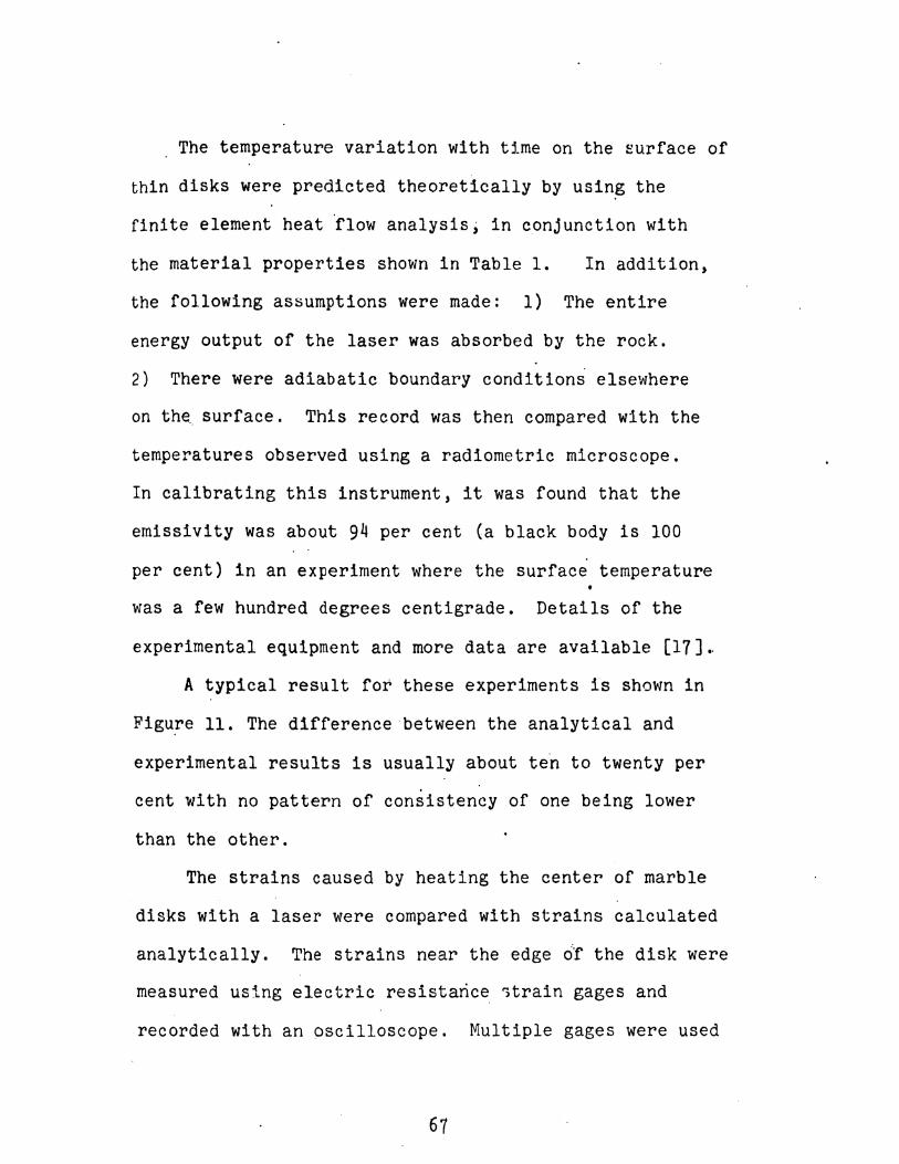
The temperature variation with time on the surface of
thin disks were predicted theoretically by using the
finite element heat 'flow analysis; in c,onjunctlon with
the material properties shown in Table 1. In addition,
the following assumptions were made: 1) The entire
energy output of the laser was absorbed by the rock.
2) There were adiabatic boundary conditions elsewhere
on the. surface. This record was then compared with the
temperatures observed using a radiometric microscope.
In calibrating this instrument, it was found that the
emissivity was about 9~ per cent (a black body is 100
per cent) in an experiment where the surface temperature
was a few hundred degrees centigrade. Details of the
experimental equipment and more data are available [17].
A typical result for these experiments is shown in
Figure 11. The d1fference'between the analytical and
experimental results is usually about ten to twenty per
cent with no pattern of consistency of one being lower
than the other.
The strains caused by heating the center of marble
disks with a laser were compared with strains calculated
analytically. The strains near the edge df the disk were
measured using electric resistaric~ 1train gages and
recorded with an pscilloscope. Multiple gages were used
67

0'\Q::)
300
,.....(.)o.........
~ 200::::> .t:f0::lLIa.~
~--OBSERVED- .-- CALCULATED
TEMPERATURE
2 3TIME (SECONDS)
4 5
FIGURE II: OBSERVED AND CALCULATED TEMPERATURES AT BACK- ..
SIDE CENTERSPOT OF DISC. THIS CONSISTED OF LASING A 0-0511 THICK
MARBLE DISC AT A POWER LEVEL a= 10 WATlS [17]
so that the effects of temperature changes of the gage
would be compensated for. Figure 12 shows both the
analytical and experimental strain as a function of
heating time. The error 1s about ten per cent with the
analytical value lower then the experimental.
3.5 SPECIFIC EXAMPLES WITH CYLINDERS
3.5.1 General. The responses of rock cylinders to
local ~eat1ng was studied both experimentally and analyt
ically in order to understand the nature of the thermal
spalllng mechanisms. The aprroach taken was to conduct
experiments in which the time required to spall at a
given power level was measured and then .using the analysis
technique to find the temperatures, the stresses and the
releasable strain energy at the time of fracture initiation.
This information allowed a prediction of spalling response
·to be made with the developed theory. This would then be
eompared to the experimental behavior for marble and granite
at different power levels, thus illustrating different
modes of failure.
The specimen shape used to investigate and study the
spalling phenomenon was designed to have ~esponses which
would be similar to that which occurs in the field. The
field cond1tlon is usually a relati,rely large mass of
rock heated over a small portion of its surface. For the

M OF 5L POWER
I
-- EXPERIMENTAL VALUES- - - ANALYTICALLY COMPUTED VALUES
2 3 4 5 6 7' 8 910 \I 12 13
TIME (SECONDS)
LASER SEAWATTS, TOTA
~ ~ ,, ~ ,~~
I MARBLE DISC I
THE DISC IS INSTRUMENTED TO MEASURE RADIAL AND TANGENTIALSTRAINS AT A DISTANCE OF o·6Cl FROM THE ,CENTER, Q\J BOTH SIDES.
FIGURE 12: COMPARISON OF EXPERIMENTAL
AND ANALYTICAL VALUES OF MEMBRANE STRAINS70 [17]

experiments, it was desirable to keep the specimens as
small as possible for ease and economy of preparation
and handling, and it was also necessary that the spec-
imens have an axis of,symmetry to render the two-
dimensional analysis progra~ applicable. The cylindrical
shape satisfied these requirements and was used for the
natural rock (marble and granite) spec1~ens; These
specimens were prepared by drilling cores out of large
blocks which were then cut to the proper length.
Spal11ng experiments were conducted on the granite
and marble cylindrical shaped spe~imens by heating at
the center of one end. A microphone was placed near th~
•heated end to pick up the sound of the spalling which
was a snapping noise audible to the human ear a few feet
away from the specimen. ,The sound of the window or the,
laser being opened was also picked up by the microphone
and when displayed together on an oscilloscope screen
gave a record of the heating time' to cause spall1ng. The
size of the heated spot was controlled by reflecting the
beam from a focusing mirror and adjusting the distance
between the mirror and specimen.
Most specimens were l~ inches long an~ l~ inches
inches in diameter. Initially tests were conducted on
shorter cylinders and it· was concluded that l~ inches of
71
length was sufficient to cause spalling of granite specimens
for the range of heating rates that were used in the exper-
irnents. This length was also easy to handle and position
in the test equipment.
:3.5.2 Variation in Length (Granite). To establish
the minimum length of specimen that could successfully
be used to study spall1ng, experiments were conducted on
granite specimens of different lengths. Specimens 112
1 1inches in diameter with lengths of 2' 1, 12, and 2 inches
long were heated on one end with the laser set at low
power and focused. By using a power in the low end of
the operational range for that laser, the conclusions
reached about the minimum length for spalling also held
true for higher ranges of power rates. This was because
at higher powers the spalling condition was reached in
shorter times, i.e. a smaller region of the material would
be heated thus requiring a smaller amount of cooler
surrounding material to'sufficiently restrain it. The
rocusing apparatus was required in oTder to heat only a
small portion of the surface.1 .
Spalling was not observed in the 2 long specimen; the
1 inch long specimens underwent some spallfng, and the
longer spe~imens exhibited very good spalling. On the
basis of these tests, it was decided that specimens l~
72

inches long would be used for all other tests.
The chips formed by the spalllng were about 3/10
inch in diameter. The front side of the chip, which was
the surface of the specimen, remained the same 1n appear-
ance with no signs of crushing or melting.
For those specimens in which spalling occured, the
temperatures and stresses were calculated with the
analysis technique for the time at which spal11ng was
experimentally observed to start. These temperatures
and stresses are shown in Figure 13and Table 2.
The tensile stresses acting under the heated area
on a plane parallel to the surface were· the largest
tensile stresses in the longer specimen and for the1
specimens shorter than about 2 inch, the largest tensile
stress 1s· the tangential one around the heated spot. Thus,
the first fracture to be initiated in the short specimens
would tend to split the specimen. However) the comb1~ation
of the large fracture area required to completely split the
specimen and the low releasable strain energy associated
with this mode would lend to a stable crack as was observed
in the experiments. After the experiment, the outward
appearance of the specimen was that it was~intact and sound
to the tou~h. The extent of the splitting fracture could
only be estimated because the analysis of the stresses
73

SUMMARY OF EXPERIMENTS AND STRESSES FOR VARIATION IN SPECIMEN LENGTHS
Material. GraniteDiameter = 1.5 inchesPower = 50 wattsLaser = 0.3 inchesTime = 2.0 seconds
No.ot: Maximum Maximum Strength** Energy· Observed Correct
Tests Conditions Tension Compression St Sc Ratio Behavior Predictionks1 ksi ksi ks1
3 0.5" long 1.42 14.8 0.78 34 .5 no spall Yes, butsee be 10''1
2 0.0" long 1.15 15.3 to 15 some spall Yes
3 1.5" long 1.15 15.3 1.56 15 good spall Yes
2 2.0" long 1.15 15.3 15 good spall Yes
-J-t=
NOTE:
* ratio of releasable strain energy to energy required to rormrracture surrace for complete spalling. .
For the ; inch long specimens th~ maximum tensile s~ress was notthe stress required to initiate a spall1ng type rracture but asplitting or the specimen. Estimates show that there is insu~~icient energy for this fracture to propogate through thespecimen.
** for tensile strength a range of ~ to full value of tensilestrength ~rom beam bending.tests is given.
TABLE 2

1-5
LASER POWER::;: 50 WATTS
LASER BEAM DIAMETER • 0-3 INCH
HEATING TIME • 2-0 SECONDS
".......-rn~..........
ffia:::
-..Jtn
V1
-5
\,,~..-------------~
/¢,~---------------
THE MAXIMUM TENSILE STRESS IN THE VERTICAL DIRECTION .UNDER THE SURFACE HOT SPOT (INDUCES A SPALLING FRACTURE)
THE MAXIMUM TENSILE STRESS IN THE TANGENTIAL DIRECTION- - - IN ANULAR ZONE ABOUT THE SURFACE HOT SPOT (INDUCES
A SPLITTING FRACTURE)
2-0'.1-0 1·5
SPECIMEN LENGTH (INCHES)
0-5o· . . , . ,o
FIGURE 13: STRESSES IN GRANITE CYLINDERS AS
.A FUNCTION OF SPECIMEN LENGTH

after· spI1ttlng was not a two-dimensional symmetric
problem •.
By comparing the maximum calcul~t~d tensile stresses
at the time spall1ng started for the longer specimens, it
is seen that these stresses are about equal to the tensile
strength of the granite.
Investigation of the calculated stress distribution
for the cylinders that underwent spalling at the time of
failure initiation shows that the max~mum compressive
stress at the surface (and parallel to it), where the
heat was applied, was less than the compressive strength
of the granite. This corresponds to the experimental
observations that the outer surface of the chip showed
no signs of crushing or melting.
The amount of energy released by tIle spalling greatly
exceeded that required to .form the new fracture area. The
area of the fracture used for the energy calculation was
based on the experimentally observed chip size.
3.5.3 Variation in Power (Granite). Experiments were
conducted on granite cylinders 11 inches by 11 inches at2' 2
three different power levels using the same diameter laser
beam. The heating time to cause spalling was recorded for
each experiment usi~g a microphone and oscilloscope. The

dat~ for the t~sts are shown in Table 3 and in Figures 14
through 18.
Figure 14 shows the distribution of the temperatures
and the stresses for a given heating time. The general
shape of these functions remains the same throughout the
typically short heating time required to cause the spalling
and for the various power levels. With longer heating
times the temperatures increase in magnitude, penetrate
deepei into the specimen and spread out further over the
surface. The tensile stress which initiates the spall
fracture 1s the Z stress shown along the centerline.
Figure 15 shows the increase in calculated maximum
temperature (on the specimen's centerline at the surface)
with respect to heating time fer the three power levels.
These temperatures are calc~lated on the basis of low
temperature material properties and may not be accurate
for the higher ranges of temperature. Therefore, the'
very high temperatures should be considered only for
illustrative purposes.
Figure 16 shows the variation of the maximum com
pressive stress and the maximum tensile stress which
causes spalling in the specimen with respec~ to the
heating time. It can be seen that for each power level
the maximum tensile stress exceeds the modulus of rupture
before the maximum compressive stress exceeds the
77

compressive strength.
It 1s to be expected that the material will fail
in tension at a level lower than the modulus of rupture
(which 1s typically from 1.5 to 2.0 times the uniaxial
strength of brittle materials). This is confirmed by
the experimentally observed mean heating time (shown
on the figure) which indicate that the calculated stress
was about ~ of the modulus of rupture.
Thp ratio of the compressive strength to the
modulus of rupture and the ratio of the maximum com
pressive stress to the maximum tensile stress which
causes spal1ing, are shown in Figure 17 .as a function
of heating time for three different power levels. If
the ratio of the stress~s i~ less than the ratio of the
strengths the tensile strength will be exceeded before .
the compressive strength is. If this is the case, then
a fracture will be initiated which will cause spalling
if there is'sufficient energy available for complete
propagation. If not, the surface will crush, and since
this will subsequently reduce the tensile stresses,· a
spall producing fracture will probably not occur. It is
seen from Figure ·11 that the ratio of stres5es is less
than the rLtio of the strengths, and therefore spalling
can be expected. This prediction was confirmed by
18

experimental observation.
Figure 18 shows the required thermal energy to cause
spall1ng as a function of power. For the granite cylinders
there was a slight decrease observed when increasing the
power from 50 to 200 watts.
In Table 3 the term "Energy Ratio" 1s the ratio of
the strain energy that would be released by complete
propagation to the energy that would be consumed by the
fracture process. Since this term 1s greater than unity
for all three power levels, it was expected that complete
propagation would occur. Experimental observations
corroborated this hypothesis.
3.5.4 Variation in Power (Marble). Experiments were
conducted on marble cylinders l~ inches by l~ inches at
power levels of 50, 100 and 200 watts. Table ~ gives the
details of the .experiments. and parameters. For each· of
these cases (and for a few trial ones at even higher and
lower power 1.evels) there was no sound of spalling recorded
with the microphone and oscilloscope· nor was there any
other evidence that spalling had occured. If the heating
was stopped before melting of the surface began, the heated
material showed signs of crushing. It could be easily
removed wi~h a knife blade.
Figure 19 shows the distribution of temperatures and
79
Granite Cylinders (l~" by l~") Heated with a Laser Beam 0.2 inches in Diameter
Mean(l)Maximum(2) Strength(3No. Heating. Maximum (4~ Agree'"
of Power Time Tension Compression St Sc Energy ~ Pred- . withTests Watts Sec. ks1 ksi ksi ks1 Ratio lction Exp.
4 50 0.83 1.25 13.3 2.9 Tensile Yes.fracture
andspall
.785 100 0.38 1.34 14.0 34. 2.1 Tensile Yes
to fractureand
1.56 spall
5 200 0.18 1.35 15.0 1.5 Tensile Yesfracture
and. spall
ex>o
(1)(2)(3)
(4)
Mean of experimentally observed heating time required to cause first spall.The calculated stresses ~or the mean heating time.The r~nge for the tensile strength is 1/2"to the full value or the modulusor rupture.Ratio or the calculated releasable strain energy to the energy requiredto form the fracture area for complete ral1ure.
TABLE 3

Jes
0::>~
-7-6 ksi -.,-------
695°C
I RADIANT HEAT
V
'!-...JIi. 0.1-....,
1-5"~
¢.. "
STRESS
- - TEMPERATURE
FIGURE 14: TEMPERATURE AND STRESS DISTRIBUTION FOR A
GRANITE CYLINDER (50 WATTS, 0·4 SECONDS HEATING)

5000
.TIME (SECONDS)
5
I
21 •
ANALYTICAL PREDICTION BASED ONLOW TEMPERATURE PROPERTIES
-2
82
IOO-------------_~ _ __L.__ __.a.___._..._ _._.
-I
10,000
FIGURE 15: . MAXIMUM SURFACE TEMPERATURE
VS. HEATING TIME FOR GRANITE CYLINDERS

52
I
~~fJO~
MODULUS OF RUPTURE-----
+-- THE 'CALCULATED MAXIMU~
SPALL PRODUCING TENSILE. STRESS IN THE SPECIMEN
(XlAPRESSIVE STRENGTH-----
r:{.~ THE CALCULATED MAXIMUMfJ 4-- COMPRESSIVE STRESS
IN THE SPECIMEN
11
·2
·1MEAN EXPERIMENTAL HEATING TIME TO SPALL
·5"'--"'_.-.........----....-_..---a__..-.I- .l.-__.-..
·1
TIME (SECONDS)
FIGURE 16: STRESS VS. "HEATING TIME
FOR GRANITE CYLINDERS83
2
50
20
5
en~ " ......,(J) 10t3IX:~ .en

. COMPRESSIVE STRENGTH / TENSILE STRENGTH2.()-~------. ~----.-
---- ---==-~-= .........._.---......----10
oij .. 50:
I
2 STRESS RATIO, 50 WATTS
- • - STRESS RATIO, 100 WATTS
- - - STRESS RATIO, 200 WATTS
. ·5'------...a.----...._-.l"---__~_ __...._'____'~·2 ·5 I 2 5
TIME (SECOr~DS)
.FIGURE 17: VARIATION WITH RESPECT TO
HEATING TIME OF THE RATIO' OF. 'r
MAXIMUM COMPRESSIVE STRESS OVER THE
MAXIMUM SPALL PRODUCING TENSILE STRESS
IN GRANITE CYLINDERS84

I
100 150 200 250 300LASER POWER (WATTS)
GRANITE
~CYLINDERS----------=
PORCELAIN----..,
SPHERES
50o...-.---....Io.-_--a.-_--..-_-.-..... .-....-_-..o
'50
200
~~LLJ..J<t 100
II-
,...
~ 150", .,......
FIGURE 18:· THERMAL ENERGY REQUIRED TO
CAUSE SPALLING VS. POWER LEVEL85

stresses 1n the specimen. This distribution 1s very nearly
like that for the granite cylinders and will c~ange only
in relative size and magnitude with changes 1n heating
time or variation of power levels.
The increase in the calculated maximum temperature
(on the specimen's centerline at the surface) 1s shown
in Figure 20. The analyses were performed based on the
low temperature properties of the" marble and may not be
accurate for the higher temperature ranges with the
accompanying phase changes. Therefore, the highest
temperatures should be considered only for illustrative
purposes.
Figure 21 shows the variation with heating time of
the maximum compressive stress and the maximum tensile .
stress (which would tend'to cause spalling in the
specimen). For each power level the maximum compressive
stress exceeds the compres~ive strength before the
maximum tensile stress exceeds the modulus of rupture.
Thus, it 1s expected that the surface would fail in
compression before a spall" producing fracture could be
initiated. Even if a tensile failure could occur at
one half the modulus of rupture, the compressive failure
at the surface would still be the fIrst mode of failure.
This crushing type of failure was the type that was
86

observed in the experiments.
A crushing of the surface under the laser radiation
has two effects which prevent spalling. First, the
local crushing relieves the spall producing tensile
stresses. Second, the crushing increases the porosity
of the material, which decreases the thermal conductivity.
Thus, a crushed layer will act as an insulator, retaining
the heat at the surface where it would cause melting and
heat 'loss by reradiation. The reduced heat flux into the
intact material underneath would tend to reduce the
thermal gradients and the thermal stresses.
The ratio of the compressive strength to the
modulus of rupture and the ratio of the maximum compressive
stress .to the maximum tensile stress are shown in Figure 22
as a function of heating time for three different power
levels. For all heating times and power levels, the.
ratio of the stresses exceeds the ratio of the strengths
which means that a compressive failure will occur first.
3.5.5 Variation in Power (Porcelain). Porcelain
spheres l~ inches in diameter were heated at three
different power levels and the heating time required to
cause spall1ng was recorded using a microphone and
oscillosco~e. Table 5 gives details of the experiments
and the parameters.
81

1 1Marble Cylinders (1
2" by 1 2 ") Heated With a Laser Beam 0.2 Inches Wide
roco
No. Average (1)strength(2)
Agreeof: Power Stress withTests Watts Ratio Ratio Prediction Experiment
3 50 10.25 11.6 Compressive YesFailure noSpal11ng
4 100 11 LJ.6 Compressive YesFailure noSpal11ng
5 200 9.5 LJ.6 Compressive YesFailure noSpal11ng
(1) Ratio.or maximum compressive stress to the maximum tensile stresswhich tends to induce spalling averaged over the heating time
(2) ~atl0 or the ~ompress1ve strength to the modulus or rupture
TABLE ij

-- STRESS·
- - - TEMPERATURE
"ct.
r1-5"
1
40 ks i..",-- ____
J RADIANT HEAT
1_5"f.4
ex>\D
FIGURE 19: TEMPERATURE AND -STRESS DISTRIBUTION FOR. A
MARBLE CYLINDER. (50 WATTS, 0-6 SECONDS HEAriNG)

5
. I
ANALYTICAL PREDICTION BASED ONLON TEMPERATURE PROPERTIES
-5 I · ~
TIME (SECONDS)
-2 .IOO'-----a..---_....t-_--L-..-_~____.... _____
-I
90
lOP00
FIGURE 20: MAXIMUM SURFACE TEMPERATURE
VS. HEATING TIME FOR MARBLE CYLINDERS
5000
,..".
oe.."2000lIJ. 0:::>
~~ 10001IJI-

5
COMPRESSIVE STRENGTH
THE CALCULATED MAXIMUMCOMPRESSIVE STRESSIN THE SPECIMEN
THE CALCULATED MAXIMUM...-- SR.\LL PRODUCING TENSILE
STRESS IN THE SPECI~1EN
91
MOOUlUS OF RUPTURE------------
FIGURE 21: . STRESS VS. HEATING TIME
FOR MARBLE CYLINDERS
·5~---------._..__ _..._ _..I_______'
·1 . -2 -5 I· 2
TIME (SECONDS)
50

I
92
5-5 I . 2TIME (SECONDS)
·2·5'"-----....&...---__"'----_-..- -.j
·1
2 STRESS RATIO, 50 WAITS
_.- STRESS RATIO, 100 YJATTS
- _.. STRESS RATIO, 200 \VATTS
50r------r----'--T--..-- -r---__---.__----.......
20
oij 5 COMPRESSIVE STRENGTH / TENSILE STRENGTH~ .. -------------------
.FIGURE 22:. VARIATION WITH RESPECT TO
HEATING TIME OF THE RATIO· OF
. MAXIMUM COMPRESSIVE STRESS OVER THE
MAXIMUM SPALL- PRODUCING TENSILE S-rRESS
IN MARBLE CYLINDERS
The distribution of the temperatures and stresses
for a given heating time and power are shown in Figure 23
These are similar ~n pattern to those for the cylinders
and c~ange in the same manner with respect to changes in
power level or heating time.
The variations in calculated temperatures as a function
of time for different power levels are shown in Figure
The analyses were based o~ the materiars low temperature
properties and may not be accurate for the higher tem-
perature ranges. Therefore, the highest temperatures
should be considered for illustrative purposes .only.
The variation of the maximum compressive stress and,
the maximum tensile stress (that causes spalling) with
respect to heating time are shown in Figure 24 for the
three power levels. Observations of the values shows
that the maximum tensile stresses will exceed the
tensile strength well before the maximum compressive
strength for all power levels. The mean experimentally
observed heating times are also depicted in the figure.
The calculated maximum tensile stresses at the~e times
·corresponds well with the tensile strength as found
experimentally by static loads on the spheres.
The ratio of compressive stren~th to the tensile
strength and the ratio of the maximum compressive stress
93

to maximum tensile stress that causes spalling as a
function of the heating time for the three power levels
are shown in ~lgure 25. The ratio-of the stresses is
larger than the ratio of the strengths for all values
of power level and heating time. Thus, the tensile
strength will be exceedeu before the compressive strength
is. This will initiate a fracture and cause a spalling
type of failure if there 1s enough releasable strain
energy for complete propagation.
. Note that the ratio of the stresses was more than
twice that for granite and marble cylinders. This is
because th~ spherical shape used for the porcelain
specimens insured a sharp curvature 1n the compressive
stresses parallel to the surface which cause the
spalling inducing tensile stresses in the vertical
direction to increase. Thus convex surfaces result in
more favorable stress pat~erns for thermal spalling.
Figure 18 shows the required thermal energy to cause
spalling as a function of power. ~or the porcelain
spheres there was a substantial decrease in the required
thermal energy with an increase in· power from'100 to 300
watts. This was not the case with the granite cylinders.
The reason for the difference was the shape of the surface
at the point of neating. For higher powers and the
9~

shor~er heating times required the large compressive
stresses parallel to the surface were much closer to the
surface and constrained to follow it with its relatively
sharp radius.
In general, the porcela.in· required more thermal
energy to cause spalling because the tensile stress required
for fracture initiation in the porcelain was' much higher
than in the granite.",
In Table 5 the term "Energy Ratio" is the ratio
of the strain energy that would be released by a complete
spall at the time of fracture initiation to the energy
that would be absorbed by the fracture process. This
term was greatly in excess of unity for all power levels,
which resulted in very high chip velocity during spallinE
for all experiments.
95

"
1Porcelain Spheres (12
" diameter) Heated with a Laser Beam 0.2 Inches W1.de
Mean (1)
Strength(3;No. Heating Max1mum(2) MaximumEnergy(4)
Agreeo~ Power Time Tension Compression St Sc Pre- withTests Watts Sec. ks1 ks1 ks1 ks1 Rat 1'0 diction Exp.
5 100 1.90 7.8 43.5 17.6 Tensile Yesfracture
andspall
5 200 0.63 9.0 52.0 8.5 70. 14.3 Tensile Yesrracture
andspall
5 300 0.30 9.3 54.0 12.7 Tensile Yes:fracture. andspall
-----/
\.00'\
(1)(2)(3)
(4)
Mean~'or experimentally observed heating time required to cause r1rst spall.The calculated stresses for the mean heating time.The rang~· for the tensile strength 1s 1/2 to the rull value or the modulusof rupture.Ratio or the calculated releasable strain energy to the energy required toform the fracture area :for complete railure.
TABLE 5

~
--.J
~ .1 RADIANT HEM .
-- STRESS- -- TEMPERATURE
t,
FIGURE 23: TEMPERATURE AND STRESS DISTRIBUTION FOR A
PORCELAIN SPHERE' (100 WtuTS, 1·25 SECONDS HEATING)

I
200
ANALYTK;AL PREDICTION BASED ONLOW TEMPERATURE PROPERTIES
100"-------"-----..&0-_-"-__'"""'-- ......--_---..·1 ·2 ·5 I · 2 5
TIME (SECONDS)
5000
IOPOO
FIGURE 24: MAXIMUM SURFACE TEMPERATURE
VS. HEATING TIME FOR PORCELAIN SPHERES'.... ~.
98

5
TENSILE STREN
I
COMPRESSIVE STRENGTH----------
THE CALCULATED MAXIMUM+--COMP.RESSIVE STRESS IN
.THE SPECIMEN
1
~~. ~ +-THE CALCUL~TED MAXIMUM
SPALL PRODUCING TENSILESTRESS IN TliE SPECIMEN
1MEAN EXPERIr.1ENTAL HEATING TIME TO SPALL
FIGURE 25: STRESS VS. HEATING TIME
FOR PORCELAIN SPHERES99
-7
·5------a.----.....--------_~ _.J
-I -2·5 2
TIME (SECONDS)
50
100
2
,...,. .--en~ 10
~

100
2
5-5 I 2
TIME (SECONDS1
-- STRESS RATIO, 100 WATTS l
- • - STRESS RATIO, 200 WATTS
- - - - STRESS RATIO, 300 WATTS
-2
~ . .. (D1PRESSIVE STREt\IGTH /TENSILE STRENGTH--------------
.FIGURE 26: VARIATION WiTH RESPECT TO
HEATING TIME OF THE RATIO OF. ~..,
MAXIMUM COMPRESSIVE STRESS OVER THE
MAXIMUM SPALL PRODUCING TENSILE STRESS
IN PORCELAIN SPHERES
20r-----~---r----,.----~----..-----
o
~

CHAPTER IV
CONCLUSIONS AND FUTURE WORK
ij.l CONCLUSIONS
There are several conclusions that can be made based
upon the results of the analytical and experimental work.
They fall into two main categories: first, the con
firmation of the analysis technique and second, the under
standing of the nature of spalllng in brittle materials.
The conclusions,are:
1) It 1s possible to analyze the temperatures and
the resultant thermal stresses with sufficient detail
and accuracy to predict and understand the thermal spalling
response of some brittle materials when locally heated.
2) The analysis technique does not require excessive
computation or precise evaluation of the material prop
erties and boundary conditions. This is because the
results of the analysis may be checked for accuracy by
comparison with results from simple ~xperiments which
validate the assumptions made about the material properties
and boundary conditions as a group.
3) Thermal spalling by local heating~on the surface
1s due to complete propagation of a fracture initiated by
101

tensile stresses acting below and normal to the heated
surface."
4) The compressive strength of the material must be
sufficiently large c~mpa~ed to the tensile strength to
prevent a compres~ive failure at the surface before the
spall producing fracture can be initiated by a tensile
failure below the surface.
~5) There must be sufficient energy available to form
the new surface area or there will be incomplete fracture
and no spalling. "This was not a problem in the limited
range in which experiments were conducted.
In regard to the above conoluslons, the following
points may be noted with respect to experiments involving
granite, marble and porcelain: The granite and porcelain
specimens spalled at the time the maximum tensile stress
was about equal to the tensile strength. The marble
specimens failed to spall because the surface material
failed in compression before a tensile failure could
initiate a spalling fracture.
4.2 FUTURE ~ORK·
The research conducted for this thes1~ can be
considered as part of a larger research program at the
Massachusetts Institute "of Technology to provide new
102

knowledge which will lead to improved rock excavation
methods. In this thesis, a rational analysis technique
has been developed to evaluate the thermal stresses
which were hypothesized as the basic mechanisms of
thermal spalling. Comparisons have been made, with good
correlation, to data from experiments which covered a
limited range of boundary conditions for a few different
materials.
ror this work to be of greatest possible use in the
development of significant improvements in rock ex
cavation methods, the analysis techniques and theory
should be applied to experimental results from tests
which have boundary conditions and heat sources similar
to those encountered in the field. Extensions and improve
ments could then be made) if required, to the technique
and hypotheses for this larger class of problems in the
following areas~
1) Automation of the analysis programs to handle the
moving ·boundary problem. '
2) Analysis of the case of surface crushing in more
detail.
3) The slow growth case where the prqpagation is
dependent on additional heating due to the initial lack
of energy.
103

Based up~n the experience gained during this thesis,
it 1s anticipated that extensions' into the following
related areas will lead to most valuable results in the
understanding and improvement of excavation techniques.
1) The application of. the arlalysis technique to
field type conditions with prototype heat sources, and
the comparison of these results to experimentally recorded
strains: The results of this would indicate the improve
ments'" required, if any J in the assumptions made about
the boundary conditions and material properties. Then
the analysis technique can be used to study the spalling
in simulated field conditions and improvements in
equipmel1t and/or operating procedure could be done in a
rational manner based on the concept of furnishing the
maximum tensile stress and minimum compressive stress in
the most efficient manner.
2) It is possible to apply the developed analysis
technique to the problem or "how mechanical bits cause
fracture in brittle materials. The ~ost difficult aspect
of this problem is to establish the proper shape and
conditions at the boundary between.the bit and the rock.
At this interface, there 1s crushed materi~l which is
controlling both the magnitude and direction of the
stresses. An experimental study of the properties and
104

flow. of this crushed material would be used to estimate
the proper boundary shape and conditions. Based on these
estimated boundary conditions, analyses could be made of
the stresses and strains. These strains would then be
compared to experimental strains obtained by placing strain
gages on the rock very close to the bit. If necessary, the
estimates of the boundary shape and .conditioris could be
modified in order to achieve the desired close correlation
between the analysis and experiments. When this is sat
isfactorily done, the analysis technique could be used to
study the initiation and propagation of brittle fracture
caused by mechanical bit action.
3) It has been observed in this work that often
heating alone cannot create a tensile failure in the prQper
location before the material fails in compression on the
surra~e. Also, there are cases in which the available
energy for spalling is sufficient to cause propagation
even though the tensile stresses are insufficient to
initiate the fracture.
For materials 1n which this type of behavior hinders
the spalling rate, a means of initiating the fracture
should be investigated. The most likely means of achieving
this seems to be with mechanical cu~ters. Depending on
the type of Qpera~ion, this could be thought of as a heat
105

assisted mechanical method or a mechanical assisted
thermal spalllng method. The study of this thermal
mechanical problem accurately and in detail, would
require that the stress problem concerning the inter
action of the mechanical bit and the rock surface be
done first. Then the method of solution would be to
rationally combine heating and mechanical methods in
the manner which would best initiate the fracture and
propagate it to form chips.
106
REFERENCES
1. Maurer, W., "Novel Drilling Techniques, Pergamon PressLtd., London, 1968.
2. Helseth, H. C. and K01.ller R. H., The Use of Rocket. Jet Burners, Soc. of Min. Eng. of AIME, Preprint
68-H-325, September 1969.
3. Fairhurst, C., Failure and Breakage of Rock, EightSy~posium on Rock Mechanics Port City Press, Inc.,Baltimore, Md. P. 335, 1967.
4. Evans, I. and Murrell, S. A. F., Wedge Penetration'into Coal, Colliery Engineer, 1962, Vol. 39, No. 455.
5. Paul, B. and Sikarskie, D. L., A Preliminary Theoryon Static Penetration by a Rigid Wedge into aBrittle Material, AIME, Transactions, 1965, Vol. 232.
6. Garner, N. E., The Photoelastlc Determination of theStress Distribution Caused by a Bit Tooth on anIndexed Surface, M. S. Thesis, Univ. of Texas,January 1961.
7. Norton, F. H., A General Theory of SpallingJ. Am. Cerami Soc. V. 8, 1925, PP 29-39.
8. Norton, F. H., The Mechanism of SpallingJ. Am. CeramI Soc., V.9, 1926, PP 446-461.
9. Norton, F. H., Discussion on Theory of SpallingJ. Am. Cerami Soc., V. 16,1933, PP 423-424.
10. Preston, F. W., Theory of Spalling, J. Am. CeramiSoc., V. 16,1933, PP 131-133.'
11. Kingery, W. D., Factors Affect1.ng Thermal StressResistance of Ceramic Materials, J. Am. CeramiSoc., v. 38, No.1, January 1; 1955.
12 .. ~asselman, D. P. H., Elastic Energy at Fractureand Su~face Energy as Design Criteria for ThermalShock, J. Am. CeramI Soc., V. ~6, No.ll, November 1963.

REFERENCES(Continued)
13. Griffith, A. A., The Phenomena of Rupture andFlow in Solids, Phil. Trans. Rog. Soc., 1921,Vol. A 221, PP 163-198.
14. Tetelman, A. S. and McEvily,- A.. J., Fracture ofStructural Materials, John Wiley and Sons Inc.,New York, 1967.
15. Paulding, B. W., Crack Growth During BrittleFracture in Compression, Ph. D. Thesis, June~965, Massachusetts Institute of Technology.
16. Rad, P. F., Personal Communication, Departmentof Civil Engineering, Materials Division,Massachusetts Institute of Technology.
17. Farra, G., Nelson, C. R., Moavenzadeh, F.,Experimental Observations of Rock Failuredue to Laser Radiation, MassachusettsInstitute of Technology Research Report R69-16,December 1968.
18. Z1enkiewicz, O. C., and Cheuney, Y. K., The FiniteElement Method in Structural and Contenum Mechanics,McGraw-Hill Publishing Co., London 1967.
19. Fuj1no, T., Ohsaka, K., The Heat Conduction andThermal Stress Analysis by the Finite Element Method,Technical Headquarter, Mitsubishi Heavy Industries,Ltd.) Tokyo, Japan.
20. Wilson, E.L., A Digital Computer Program for the FiniteElement Analysis of Solids with Nonlinear MaterialProperties, Technical Memorandum No. 23, AerojetGeneral Corporation, July 1965.
21. Carslaw, H. S.. , and J. C. Jaeg~r, Conduction of Heatin Solids, Oxford University Press, New York, 2nd
. ed., 1959.
108

BIOGRAPHY OF THE AUTHOR
Name: Charles R. Nelson
Born: September 23, 1940, in Grafton, North Dakota
Education:
Secondary Schools in Grafton, N9rth Dak6ta
Sept. 1958 to June 1962: University of North Dakota
Sept. 1962 to present: Massachusetts Institute ofTechnology
Received the degree of Bachelor of Science from theUniversity of North Dakota in 1962, the degree ofMaster of Science from the Massachusetts Instituteof Technology in 1965 and the degree of'CivilEngineer in 1967.
Professional Experience:
June 1967 - Jan. 1969: Staff Engineer for Simpson,Gumpertz &Heger Inc., Consulting Engineers.Cambridge, Massachusetts.
Sept. 1966 - June 1967: Instructor in the CivilEngineering Department at the MassachusettsInstitute of Technology. Cambridge, Mass.
June 1964 - Sept. 1964: Engineer for LincolnLaboratory, Lexington, Massachusetts.
Sept. 1962 - June 196~: Full-time Research Assistantin the CiVil Engineering Department at theMassachusetts Institute of Tech~ology. Cambridge,Massac.husetts.
Honors:
The author graduated Cum Laude from the University ofNorth Dakota and received the Outstanding CivilEngineer A'l1ard of 1962", He was a National Science~Fellow from 1964 to 1966,
'lOg

BIOGRAPHY OF THE AUTHOR(Continued)
Publications:
Massachusetts Institute of Technology Report,;R64-37 "The Dynamic Response of Reinfurced:Concrete Circular Arches".
Massachusetts Institute of Technology ReportR69-16 "Experimental Observations of RockFailure due to Laser Radiation~'.
The author was married to Marlys Brown in 1959and 1s the father of two children, Klmberleeand Brent.
. .The author 1s joining the School of Minerals andMetallurgical Engineering at the University ofMinnesota as an Assistant Professor of GeoEngineering.
110
APPENDIX A
HEAT TRANSFER BY THE FINITE ELEMENT METHOD
,In th~s method the body 1s considered divided into .
small finite sized elements which are kept compatible
with each other and also satisfy overall thermal equl1ib-
rium. The problem 1s thus transformed from solving
a differential equation with boundary conditions to one
of solving ordinary simultaneous equations.~
The finite element method of heat analysis developed
here will handle most types and shapes' of linear bound-
ary conditions. Nonhomogeneous and nonlsotropic rocks
can also be handled, but the inhomogeneity must vary
slowly when compared to the finite element size. The
nonlinear aspects of the problem may be handled by u~ing
the incremental loading approach. Using this approach
the load is applied in small increments such that linear
boundary conditions and material properties may be used.
during that increment of load. At the end of each load
increment, new boundary conditions and material properties
are calculated for the next increment of load.
For the finite element method the size and the complex-
ity of the problem that can be handled. is limited by
III

the amount of computation time available. There are two
classes of pro~lems which require a much reduced number
of calculations and still provide solutions useful in
many types of real problems. The first class 1s that of
plane strain. This condition is approximated in thin
slabs. The other class 1s the ax1-symmetrlc one in which
all boundary conditions, loadings, and material properties
.3.re symmetric to a single axis. It 1s the type of prob lem
'chat"exists in discs and cylinders. By virtue of the
symmetry in such a case, only one pie-shaped wedge need be
considered. This effectively reduces the three-dimensional
problem to a two-dimensional one.
A method to evaluate heat transfer by the finite
element technique for rock specimens subjected to laser
radiation has been developed in the following manner:
In general the element shape in this work 1s tri
angular and the temperature within the eJement is assumed
to be a linear function of the x and y coordinates:
T = A + Bx + Cy
The values of A, B, and C must be ex~ressed in terms
of the temperatures· at" the three corners of the element
called Ti' T2 , and T 3 •·
112

adX
(TK )y
a-3Y
113
(TK )t dx +y
aelY
and j 1s:
The heat flow of the edge of an ele~ent between points i
where Kx and Ky a?e the conductivities of the material
in the x and y dlrectio~ respectively.
and in the y direction:
1 Xl YI A
= 1 X2 Y2 B
1 x 3 Y3 C
A 1 Xl Yl-1
T 1
B = 1 x2 Y2
C 1 X3 Y3
For a given element, the heat flow intensity in the x
direction is:
qx - - a (TK )n- x

element, the intensities become:
Y, one finds:
K aTYdY
K aTxdX
ll~
qy - - Ky C
q - - K Bx x
qx
k
....-.------ x
y
The values of B .and C in terms of T1 " T2
, and T3
are:
on substituting for T in terms of A, B, C, X and
iIf the value of conductivity does not vary within an

That 1s
1s the area of the element
are the coordinates of the
1 xi YiA = 1 1 xj Yj2
1 xk Yk
rj q dy + rk q dy + JY i q dy = 0Yk x Y
jx Y
kx
115
an element of either q or q would be equal to zero.x y
It should be noted that, if the element were of con
stant thickness, an integration around all three sides of
which 1s
where xi' Yi ' xj ' xk ' Yknodes of the element and A

Therefore the element, by itself, 1s in thermal equilibrium.
However, along a boundary between two elements there will
be, in general, a discontinuity in the heat flow intensity.
This discontinuity will be assumed to cause the temperatllre
along this boundary to change. This is expressed analyt
ically in the following way. The heat flow out of an
element 1s assumed concentrated at the ~earest node. Thus
the heat into node i 1s:
IXx j IYtq dx + 1 j tq dy
Y 2 Y x1 1
•The total heat flow into node 1 would be found by summing
over all the elements containing node i :
Q = I: Qitotal
If node i changes in temperature, all elements containing
node 1 must change their internal temperatur~ distrib-
utions in a linear fashion. This follows from the initial
"assumption that the temperature is.at all times a linear
function of the space coordinates.. .
It is now possible to find·the heat required to change
the'temperature of only.one node of an element. This term

117
change 1s as shown:
T[(x Y -x y ) + (y -y )x +k j j k k j
IjCP = tp(SpH)
(X -x )y]dxdy = 1 tp(SpH)TAj k 3
element---
------ temperaturefunction
Thus the heat required to raise only one node to a given
temperature, with. a linear distribution within the ele-'f
ment, is 1 that required to raise the entire element to3
that temperature. Since· there 1s, in general) more than
by T 1s:
the heat required to change the temperature of node i
Assuming that the thickness (t), ~enslty (p), and
specific heat (SpH) are constants within the element,
1s analogous to a structural stiffness. The temperature

118
at a riode of:
Summing over the several elements at a node:
= 1 tA (HG)3
HG = Heat Generated per Unit Volume
HGN
·HGN = EHGNtotal
CPT = E CP
Boundary conditions at any point may pe specified..
in one or more of the following ways: given temperature
(e.g., water bath), given heat flux (e.g., laser), ra-
the nodes.
heat capacity of each element was divided equally among
equally to each node of the element in the same way as the
it would uniformly raise the temperature of that element.
Th1s~·wil1 be accounted for by having this heat divided
If there is any heat being generated within the element,
all adjacent elements giving a total heat capacity (CPT). .
one element at a node, the effect must be summed over

given temperatures.
at the nearest boundary nodes.
of elements to account for the conductivity of the
aT CPT = aat
lig
means differentiation with respect to time.a
at
Qtotal + Qboundary + HGNtotal -
written as :
Tboundary = Tgiven
Qboundary = Jf qboundary,
boun,dary condi tlon.
The heat equilibrium equation at each node can now be
The conductive zone is handled by adding an extra layer
The ~~diation and flux conditions are assumed concentrated
dlat.ioI1, or a ,conductive zone to some given temperature.
the boundary nodal temperatures are held fixed at those
as a set of given temperatures is "easy to analyze since
The case in which the boundary conditions are specified
'boundary layer and thus converting it to a fixed temperature

the system would be equal to the total number of nodes
120
Qtotal + Qboundary + HGNtotalaT CPT =at
If we let:
~hus, at this point, there are N equations, NaTunknown temperatures, and N unknown --, that 1s, aat
total of 2N unknowns. If the steady state solution 1saT .
wanted, the N unknown at' s are zero. .The system now
has N unknowns and N equations which can be solved.
temperature was given would be nUll.
would be the same as the number of unknown temperatures
since the equations for the boundary nodes where the
perature was given. The number of independent equations
minus the number of boundary nodes at which the tem-
An equation of this nature can be written for each node
in the system. The number of unknown temperatures in
. We get:

The temperature in the future, Tf , is predicted in terms
of the present temperature, Tp ' and the time increment,
6t, into the future. The Qtotal' Qboundary' and
HGNtotal are functions of the present temperatures and
known boundary conditions. The temperature for all
future time can now be found by marching the solution
out from some known initial boundary conditions.
The maximum rate at which the solution can be
marched forward in time 1s controlled by the stability
of the sOlution. To find the maximum rate, the following
logic 1s used:
Assume there is an error introduced into the solution
at some point due to round off or other causes. If this
does not diminish with time, the solution will become unsta-
ble. If the system had zero values throughout except for
an error (E) at one node, then this error should diminish
with time. Initially, Ti
= E, all other T = 0 and the
heat flow into node i is Qtotal + Qboundary' After one
time increment At the temperature at ·node 1 1s:
Q + QT (At) = (total boundarY)At + E
1 CPT
121

Now if:'
IT (~t)1 > IT (0·)1i 1
there 1s instability since the error may grow with time.
For the limiting case:
IT (l1t) I = IT (0) I1 1
which gives:
Qtotal + Qboundar~CPT ~t = 0, -2E
For the first case a lower limit on ~t 1s zero, that
is, in a heat transfer problem one can not predict back
in time. The second case will give the maximum rate
at which the solution can be marched forward. Neglecting
the Q (boundary) term:
Qtotal--- ~t = -2E
CPT
122

one dimension the condition 1s:
have zero temperature and the problem 1s linear, E can
x1+2
2CPT
Qtotal(l)
~t = -2
123
-------,-E
o < ~t <
Qtotal(l)CPT
i-2
T
where Qtotal(l) 1s the Q of that node which has a unit
temperature and all other nodes have zero temperature. In
be factored out of Q After cancellation of Etotal-
there 1s for the limiting case:
ones adjacent to it. Since, initially, the adjacent nodes
node 'to another.' The Q 1s a function of these astotal
well as the temperature of the node in question and the
arrangement and material properties, and varies from one
CPT is a function of the element size, shape, thickness,

If the initial conditions are as shown, the time in
crement (~t) must be limited such that after (~t),
T. is less than E but greater than -E.1
Note that the minimum v~lue of ~t must be used
after checking all nodes and also that CPT grows with
element size, and Qtotal (1) diminishes with element
size. Thus smaller elements require smaller time
increments."
The computer program to do the heat transfer was
checked by considering a problem which was solved in
closed form [21J. The problem consisted of a wall at
constant temperature which, at time zero, had its out
side surface temperature changed to zero. For the
computer solution the wall was'split (about its axis of
symmetry) and one half of it was represented by twenty
elements such as:
= 0
o
•
12~
\

The computer solution was within 0.1 per cent of the plots
for the closed form s~lution given by Carslaw and Jaeger.[21].
In varying the time increment in this p~oblem, the derived
limit for stability was established.
125

APPENDIX B
(Approximate)
~ (0 a +0 a +0 a )E x Y y z z x
126.
PE =
=
+
strain energy per unit volume is then:
Where Vi 1s the volume of the element. The total
An approximation of the strain energy in the body can
be obtained by assuming that for the case of suddent
It was necessary to calculate the strain energy in
STRAIN ENERGY CALCULATION
N
PE = ~ PEi1=1
where N is the total number of elements.
energy is then
in element 1 is [ ]:
the specimens before and ar~er the formation of a spall.
finite element over all of the elements. The strain energy
This was done by summing the strain energy in each
._ heating at .the surface the strain is limi ted to one
dimension (in the direction normal to the surface). The

where AT is the change in temperature applied to a single
element 1s:
where ~Ti 1s the change in temperature of the element.
The total energy is:
N
PE =~ PE11=1
The comparison of this approximation with the exact
value shows that for the cases investigated in this work
the approximation is about four times the exact value.
This means that displacement parallel to the surface
reduces the stresses by about a factor of two from the
stresses that would exist if the problem were truly one
dimensional. The more precise method requires that the
stresses be evaluated while the second method only
required knowledge of the temperature~.
127

APPENDIX C .
DETAILED INSTRUCTION FOR "J.HE ANALYSIS TECHNIQUE
The required modeling and data preparation for the
analysis technique will be shown for a thermal stress
problem.
First, to evaluate the temperature distribution,
the appropriate boundary conditions and material properties
must ··be known or estimated. For granite the following
estimates of the properties are based on published data [ ]
Conductivity = 1./(31500 + 21.6T)BTU in sec of
Specific Heat = .21 BTU/lb of
Density = .094 Ibs/1n3
The boundary conditions are the estimated heat flow
into and out of the material. For this example the heat
flow into or out of the boundary of the specimen at all
places other than that area heated by the laser are
assumed to be zero. This assumption has been proven
valid for short heating times with the laser in which
the surface does not become incandescent.
128

It is estimated that the total energy of the laser
(as recorded by· absorption in the power measuring
calorimeter)' is .absorbed by the rock. This estimate
appears to be valid because the surface has several
impurities, such as water and dus~, and has irregularities,
such as micro-cracks and adhesions all of which tend to
increase the surface absorptivity. The estimated shape
of the beam 1s that of an axi-symmetric gaussian curve.
Thes~' estimates are accurate if the laser 1s operating in
a single mode, which 1s normally sought in operation for
accurate targeting of the beam.
The specimen to be analyzed must be modeled by a
finite number of triangular elements. Since the
temperature can only vary in a linear manner in any element,
each element must be sufficiently small such that the true
shape of the temperature function can be well estimated
by the small straight segments.
For the example under consideration the shape is a
cylinder) 112 inches long and 11 inches in diameter. Of2 ·
this, only the top center zone which ~ill experience an
increase in temperature need be modeled by the· finite
elements. That part of the body which re~ains at a
constant telnperature does not affect the solution at its·
accuracy.
129

The mode~ used for this example 1s shown in Figure 27.
Note that due consideration has been given to the axi
symmetry of the problem.
The input for the computer program is shown in the
listing. The first line,of data input has the
following meanings.
TERM
KTMAX
KTPRT
NODES
NOEL
VALUE
200
10
53
79
130
. PHYSICAL MEANING
The total number of time
steps the program will
take.
The number .of time steps
the program takes between
printing of the tem
peratures.
The exact number of nodes
(joints) there are in the
model.
The exact number of el
ements there are in the
model.

TERM
DENS
SPHET
DTIME
COND
BTEMP
VALUE
.094
.21
.02
1./(31500+2l.6T)
o.
PHYSICAL MEANING
The density of the material
(lbs./in3) •
The specific heat of the
materl~l (B.T.D./lb.)
The step size in time the
program takes in finding
new temperatures.
The thermal conductivity
of the material (B.T.D./
in. ~F sec.) (this input
1s overridden by the non-
linear function for the
conductivity in the
program. )
The temperature any bound-,
ary may be fixed at. (not
needed for the- example) (OR)

tory
~
1.
...,
47, x~ i 9_. . . =" ~ " -,
~
Wf\.)
21 UNDERLINED NUMBERS- ARE ELEMENT NUMBERS
FIGURE 27: GRID FOR HEAT TRANSFER (SEE FIGURE 29 .FOR FINE GRID)

The next group of input which 1s labeled "nodal
data" is established ill the following manner.
The first term is the radial coordinate in inches
and the second 1s the coordinate in the vertical direction
in inches. The third term 1s the initial temperature
of the body at that node. For this example the bodyowas estimated to be at 70 F initially. The fourth term
1s the net heat flow into the node 1n B.T.U. per second
due to outside sources such as the laser. It 1s zero
except for those nodes at the surface heated by the
laser. This heat flow per node is equal to that heat
which 1s incident on the surface which" ~s closest to
the node in question. The fifth term denotes if that
node is a boundary node which must be held fixed at the
specified boundary temperature. If th"1s term 1s negative,
the node 1s not held to the boundary temperature. It
should be made positive if it is desired to fix the node
at the given boundary temperature such as would be the
approximate case for a water bath for example. For the
laser heating example, this term should be negative for
all the nodes.
The next group of input data is the information which:.
tells the computer how to connect the nodes with elements.
133

Each element should have the three nodes associated with
it listed in the same order as the coordinate system. That
is, number the nodes counter-~lockwise in a right-handed
coordinate system and clockwise in a left-handed coordinate
system.
This ends the required input. The rest of the output
1s data that the program generates and 1s printed to help
in checklng the input for error. The next group of print-
out.are the number of the elements which touch each node.
A rapid comparison~ of this with the figure will indicate
if an error has been made in the input of the element
nodes.
The next·group is the area of each element printed
in numerical order. Again, a comparison of this data
with the figure looking for elements with common areas
is a quick way to check the accuracy of the input.
Following this is data on the total specific heat
of each node. It has little value as a check of input
data, but is included as a possible aid in debugging the
program if changes to it are ever made.
All of the data printed out from this point is the
temperatures of t~e nodes after a fixed integer number of~
time steps forward in time. The term KSTOP is the number
of time increments whic~ have posted before the temperatures
are reached. This can be converted to the amount of heating,
134

time by multiplying the KSTOP by the DTIME. Th~ DTIME
1s the size of" the increment in seconds.
Following each print of the KSTOP is the temperature
of each node listed in numerical order.
Once the temperatures have been. calculated over the
range of times of interest, it 1s necessary to calculate
the thermal stresses for specific times. For the thermal
stress analysis, the body 1s modeled by many finite
elements as it was for the heat transfer analysis. However,
there are two modifications required for the thermal stress
grid. One is that the size of the elements may have to be
of a different size for sufficient accuracy. Second, the
whole body must be modeled because the stresses in the
heated zone are influenced by the restraining action of the
material which remains at room temperature. With this in
mind the body is modeled by the grid shown in Figure 29.
The input for this problem 1s shown in listing
Following this is the information on the stress. analysis
program called "Feast In distribute~ by Professor John
Christian of the Soils Division of the Civil Engineering
Department at the Massachusetts Institute of Technology.
Professor Christian is in charge of the implementation
135

of this computer program at the r~assachusetts Institute of
Technology's Computation Center. This information explains
1n detail the input and output of the program for thermal
stresses.
;For the example under consideration, the use of the
temperatures from the developed heat transfer computer
program in the stress analysis computer program requires
interpolation of the data because the grid size 1s smaller
in the stress analysis program. This interpolation can
be done 1n a linear manner because the heat transfer
a~alysis program is based on the assumption that the
temperature is a linear function across each element.
One apparent difference between the two computer
programs is the use of quadrilateral elements along with
triangular ones in the stress analysis. This presents
no problem whatsoever because the only information exchange
between the two programs is the nodal temperatures and no
information which requires an element correspondence. See
Figure 29 for the model used in this example.
136

~. tR
...I , I I I I , 'fL...., JQ" I" '" ">I ." 2. -+
~
23 , 22 I 11 I ~ I !l .~
47 iR Se'l '9 ' 1)1 9 i ~ .• I I i I I i
14 ~
& !Q.
J-'
, I15 • .2- -LA)
--J
14 9- I6
21 UNDERLINED NUMBERSARE ELEMENT NUMBERS
FIGURE 28: GRID FOR STRESS ANALYSIS (SEE FIGURE 29 FOR· FINE GRIP)

. 30 ~
2840
501 6B\ "I 01 \ '191 uVl 'tIl -71
1'.
84 75 69 63 57
..§§. .§Q ~ 4~ 42J 30
51 79 44 70 39 ~A 3 27
1--' I 76 /1 §J! / 160 /°1 :&. / 173 67 !!. M
lA>ex> 8 76 71 64 59 5585 M
:a 68 62 56 50
52 81 45 72 40
75 69 §. 57
86 82 77
76 70 64 58 '52
53V 46V 41V ;z+1! ........, 53 83 46 1.! 41 62
HEAT TRANSFER GRIDSTRESS ANALYSIS GRID
FIGURE 29: FINE GRID FOR FINITE ELEMENT PROGRAMS

PROGRAM "FEAST 1 - 65"
USER'S MANUAL
DATE: MAY 1967
LANGUAGE FORTRAN IV G LEVEL
PROGRAMMER: E. L. WILSON (UNIV. OF CALIF. 1966)
MODIFIED: JOHN T. CHRISTIAN, M.I.T.
DESCRIPTION: The purpose of this computer program 1s to
determine" the deformations and stresses within certain
types of stressed bodies. The program will analyze problem
situations in any of the following cat~gories:
Axial symmetry
Plane stress
Plane strain
Elastic, non-linear material properties are considered by
a successive approximation technique. The effects of dis
placement or stress boundary condition, concentrated loads,
gravity forces and temperature changes are included.
PROGRAM CAPABILITIES: The following restrictions are
placed on the size of problems which can "be handled by the
program.
139

Item Maximum Number
Nodal Points goo
Ele~ents 800
Materials 12
Boundary Pressure Cards 200
The program incorporates a data-gen~rating facility where
by only a minimum amount of information neeo. be inputted
to specify the problem topology and geometries. Use of
this capability is described in the next section. The
program permits the use of quadrilateral and triangular
elements, as well as skew boundaries. If specified, a
data deck will be punched to provide the source data for
STRESSPLOT. This plots the vectors of major and minor
principal stress for each element.
Printed output includes:
1. Reprint of Input Data
2. Nodal Point Displacements
3. Stresses at the center of each element.
4. An approximate fundamental frequency. (The
displacements for the· given load condition
are used as an approximate mode shape in the
calculation of a frequency by Rayleigh's pro
cedure. A considerable amount of engineering
judgement must be used in the interpretation
. of this frequency.)
140

Running time for typical problems 1s about 10 mins.
INPUT DATA FORMAT:
A. IDENTIFICATION CARD -(20A4)
Columns 1 to 80 of this card contain information
to be printed with results.
B. CONTROL CARD - (415, 3F10.2, 315)
,
Columns 1 - 5 Number of nodal points
6 10 Number of elements
11 - 15 Number pf different materials
16 20 Number of boundary pressure
cards
21 - 30 Axial acceleration in the Z-
direction
31 - 40 Angular velocity
41 - 50 Reference temperature (stress
free temperature)
51 - 55 Number of approximations
56 60 = 0 A~lsymmetr1c analysis
= 1 Plane stress analysis
= -1 Plane strain'
65 = 1 A deck of stresses and
di~placements will be
punched.
141

C. MATERIAL PROPERTY INFORMATION
First Card - (215, 2FIO.O)
•Following Cards - (8FIO.O) One card for each temper-
Poisson's ratio - vrz
Modulus.of elasticity - EePoisson's ratio ver and vezCoefficient of thermal ex-
elastic modulus .
for which properties are given =
8 maximum.
pansion as
80 Yield stress 0y
any number 1 to 12.
6 - 10 Number of different temperatures
1 - 5 Materials identification -
ure
1 - 10 Temperature
71
pans ion - a and ar z61 - 70 Coeffic1~nt of thermal ex-
11 - 20 Modulus of elasticity - Erand Ez
11 - 20 Mass density of material
21 - 30 Ratio of plastic modulus to
21 ~ 30
. 31 - 40
41 - 50
51 - 60
Columns
Columns
The following group of cards must be supplied
for each different material:
,

Material properties vs. temperature are input
for each material in tabular form. The properties for
each element in the system are then evaluated by inter
polation. The mass density of the material is required
only if acceleration loads are specified or if the
approximate frequency 1s desired. Listing of the co
efficients of thermal expansion are necessary only for
thermal s~ress analysis. The plastic modulils ratio and
the yield stress are specified only if nonlinear materials
are used.
D. NODAL POINT CARDS - (215, 5FIO.D)
One card for each nodal point with the following
information:
Columns 1 - 5 Nodal point number
10 Number which indicates if dis
placements or forces are to be
specified
11 - 20 R - ordinate
21 - 30 z - ord~nate
31 - ~O XR
41 - 50 XR
· 51 - 60 Temperature
If the number in column 10 is

Condition
0 XR 1s the specified R-load and
XZ 1s the specified Z-load. free
1 XR 1s the specified R-displacement and
XZ ls the specified Z-load.
2 XR 1s the specified R-load and
XZ is the specified Z-displacement.
3 XR is the specified R-displacement and
XZ 1s the specified Z-displacement. fixed
All loads are considered to be total f6rces acting
on a one radian segment (or Ulli t thickness in the case
of plane stress analysis). Nodal point cards must be in
'numerical sequence. If cards are omi tted J the onli tted
nodal points are generated at equal intervals along a
straight line between the defined nodal points. The neces-
sary temperatures are determined by linear interpolation.
The boundary code (column 10), XR a~d XZ are set equal to
zero.
SKEW BOUNDARIES
If the number in columns 6-10 of the nodal point
cards is other than 0, 1, 2 or 3, it is interpreted as
the magnitude of an angle in degrees. This angle is,shown on the following page.
1~4

s
One card for each element ..Element number
145
6 10 Nodal Point I
1 - 5
21 - .25 Nodal Point L
11 - 15 Nodal Point J
16 - 20 Nodal Point K
XR 1s the specified load in the s-dlrect1on
XZ is the specified displacement in the n
direction
Columns
E. ELEMENT CARDS - (6I5)
1s the same as -179.0 degrees. The displacements of these
nodal po~nts whi.ch are printed by the program are
ur = the displacement in the s-directlon
Uz = the displacement in the n-direction
The angle must always be input as a negative angle and
may range from -.001 to -180 degrees. Hence, +1.0 degree
rThe terms in columns 31 - 50 of the nodal point card
are then interpreted as follows:

26 - 30 Material Identification
1. Order nodal points counter-clockwise around
element.
2. Maximum difference between nodal point I.D.
must be less than 50.
Element cards must be in element number sequence. If
e'lement calads are omitted, the program automatically
generates the omitted information by incrementing by one
the' preceding I, J, K and L. The material identification
code for the generated cards is set equal to the value
given on the last card. The last element card must
always be supplied.
Triangular elements are also permissible; they are
identified by repeating the last nodal point number (i.e.,
I, J, K, L).·
. F. PRESSURE CARDS ~ (215, IFIO.O)
One card for each boundary element which is
subjected to a normal pressure.
Columns 1 - 5 Nodal Point I
6 - 10 Nodal Point J
11 - 20 Normal Pressure
Pressure

As shown previously, the boundary element must be
on the left as one progresses from I. to J. Surface
tensile force is input as a negative pressure.
PROGRAM USE:
a). USE OF THE PLANE STRESS OPTION
A one punch in column 60 of the control card
indicates the body is a plane stress structure of unit
thickness. In the case of plane stress analysis, the
material property cards are interpreted as follows:
Column 11 - 20 Modulus of elasticity Er
21 30 Poisson's ratio•31 - ~O Modulus of elasticity Ez
The corresponding stress-strain relationship
·used in the analysis is
a lJ 'V 0 ~rr
E£
" = rX v 1 0 zz -Z
ll-'J2
0lJ-~
2(lJ+v)
where
ErEz
147

b). USE OF THE PLANE STRAIN OPTION
A punch of -1 in column 60 of the central card
indicates that the body is a plane strain structure. The
material property cards are interpreted as follows:
Column 11 - 20 Modulus of Elasticity Ev21 - 30 Poisson's Ratio v
vH31 - 40 Modulus of Elasticity E
H41 50 Poisson's Ratio 'J
HH
The program must be run on the IBM 360(65 with the as
control cards. Two scratch tapes must be mounted on
logical units 8 and 9. The source program has been
punched on the 026 key punch (BCD).
1~8

('1)01
000'0('0100t)4000'»~OOh
1),107OI')~A
-:lO('Q001"(fl·! 11)01?O'll"""\4'Ol~
0016')017'OlAC"lq(V) ?f)
C" II0(')2;»1)013
')024(\':l'J I)
~)?"
(\(' ?1O~2R
')'),qoa 3('0'" 10012r~'3t)~14
O'l'~
nt:'"\6C~ 11~('),q
11 0 ,qCf')4 t"
r.r 41('(}4'a1)'.\0 .... 4/.
104"
, .
l)1~E~SI'J~ X('3C •• Yl~O't tCd0), Fed')J, ~FI(I~C)t L~nlJC~,).3).
1 \~ F ~ Cq0). T... Ie K( ~" ), He"PI R') », l c qt)." ~c flL ( d", ~). THe: ~ P ( A) I ,Z,,(~O), cc~n», ,)(~~I, '~r)tl(~~1 , 'C(~("
JtMF:~C;IO~ C;FC~OJ
READ (., ,1 J KT~4\X.( fP~r ,Nnl)":s,~O(l ,flE-..S, SPHt:T ,:)T 1;\1E ,C'JNJ, -iTEMPWQ IfF (h,ll ,<T"'l'(,('PPf,"4nCr4i''''r'(l,Uf:~S,SflttF,,:lTI~f.C'l~),iTF"tPOJ lOt =1 , ~nl) [ "
~ fA::> (". ~) ~ ( I ) , vCI • • T( t 1• F ( I I • ~j F I l( ( I »WR I , f. (h, 7) KCI • I Y( I I , T( I , ,F' ( I ) • ~ r IKe I )
1" crN'I~tJE
f)l) 1\ I =t • \ r f lItE It a CI), 3. l'~"fl ( I • 1 ,. l Nn n( I • 'J • • l .~naIt. ~ ;WR I TE. (b." I l ""0 CI • \ I •L~"n(I .?-) Il ~OClI I • ')
It r:'1~TI~U€
1 F~RVAT (4'~, ~flC,"
1 S:"Q'1AT (4f 17. c;.IQI1 .=r,Qt4AT (':\I})
~ F~RYAT (4FI~.~)
(IJ Nr)x:: Ct1~ !)
C'1P~ 1v :Cf~" nr)l] ,C' °1:: 1 • ~rt~ lII =l ~ °'0 ( I • , ,l ?: l Nr' 0 ( It? )l 1 =L~ In I I I '\ »~ ~ FA' I »:: X ( l 2 • ,: V ( l 3 I t XIl " »• Y(l 1 •• x (l. 1 I ,. YCL ~ 1- ~ ( l ? I " Y( l 1 »-)( (l "\ ) *
IVIL'I-KCll)s1IlllA~E.\( II =..~RF~( til'.THIC~(J'=(~Cll).X(l'I+~(l'I)"~.
?" ~iC APe I I .: 0 F 'I S• SPH ( TeA Rf ,,( I • • T~. I C. I( C I )W~lrF .~,2~:') (l\LJ~\CI', t:l,'4~fl)
~(' ,., FIJ~ .., A, (7 [, 1. 5 •
0" '1 2 I: t t ~~ ~ [) '= '\III 1= 1f)~1 , , J:: 1 .'J (l [ I.,)r '; K = 1 , '\Ir (I -1. '.: f' f) ( J • <. I» , :;. :' I • ' 5
2c; r:n'1 T I ~U [t;'l Tn 2:'
?l lll)=lCllt'll=l.(11~nOl ( I ,ll • =J
~ ., r: l j ~'I TIN t Jr.')( \ r; f' 1 I =1 , ,... f) nF S"'~1 fi (1,,1r41 Ill:: leI)¥=ll'-I~.1 f l C't ,4 '} f» (r~n 1 L ( t , J' ,J =1 , ~)
4 r r: f -) P '-1 ~ r I' I~ , .....
149

'046"~lt 1
OO'tq
""4Q00')1"'(',1'l1
00 r.;,
,,', C) '\
00'\4Cf'\c;e,pn')~
O~)C; 1
"0""0(\"1')O~"('
C"ht"~6,)
""Il'('t'1"4"f)br,('f" lJh
""~1
"'')''~t'0hf)00 1~
(~71
~~1'
~,)14
001')orlh"I'll,~t11~
":)1<l10"('\'r-t,,, 1f.')A'orq,Ct(\~4
"f'\Q'"n(' AI,
~"Jtl
:'l"1~R
""qQ00Q"\=")'11
,
C,(\I C(~fl'H'C:
f':n"" I~~.\rl)(~
Tdf I\P CI I = • I)
L' :: ll' t1" 2" J: I ,l I.~ : ~, 'q l ( , • .I )
, , '·.C ht' « 1 I :. T~.c .\P ( I I. ~.r. A" C~ II " •"'=~'lJr. ~
~~ I 't Ci• • ?,.. (' I • f H( !l~' t I I, I: 1• " JK<;' '(\::CI(TI'4£=r
" ~ '<. \, 1r' : ~ c; , r' Ot Ifsr : o.rn," '2 1:: 1 • "r') ~ C\'~,:~r: 1'( CI IIf<<~1 ':'.1 1 1,1"
111 "«C;Tf~P-l) ".\\.\'", 1', I I : C,( 1 I • '\ , ~ "'.' ! I , •
r;~ '1 ,?'\ t ,( I , '= ~ 1 [ ,••)-- , ( f" ~ , I ·.tl l '
fl'" '\ I. I -= 1, ..~ r,. t
ll=l~llJCI."
l} =l N,';" ( , • l. Il ~: l .~: ~ r ( I • 'I, 'l '1 ( l I , I : ( , (I. 1 , t , CI ) I • Tit ~) I I 1 •
'\11 ) ~ CCVt I ll-Y ('-, I I "r Till J • (V (I 1 J -y Il '11--' ( l} I t I v Il "} I-V (ltl I_t , Il l) ) I J. / "fJ r- .\ ( I ,
-- I. r. ( I J :: I I (( l "\ I - • ( L ') J I .. T(l t ) • ( ~ Ill' - xCl til ~ Tel ? I • ( -: II 2 I - ( ILl. I.'fll '. tll./\t'r\c IIn' ~ 4(' I =1 , ~ r ~'JF s'le I ) =f C1 )LI =L ( IIr)' ~r J=t ,t t~~ I J =~ li) l ( I • J Ir. r "... ) x = 1. I C \ t c, j r. • ? t ." .. T~ l," l ( "! I . I J , »r.i~41)V = cr"f1 (1 1 : -!\, ria (' I J I t. r. I ~ ..~ , ) (~ r H t c -.;. ( .... , I JI')'-:: -c (\ 1I J I"~r.,u~ lY l': r.n rl( ('~) l.J Jt( :."'",e, K=ktlIf (.1(-'1 4 7,.#.),4\
41 rr"l'~rINlff
.... I{ I Tf- (~)' 1') J )
~ lol I Tf ((, , 1 j~ '. I..~ I r f- (f), 1 ),) J
1"'4 F~~\1"T I"H 1=1"), " e:. F:: Q ~.\ r (~~ J =I , I
15·0

OOq:,OCq100-14"Oqt;(\OQ6COQ7OOQAOf)qQ
Olor"lelriC?OlC,\('104(\\CltOlljb01·'1t'10~
(' lOt.l
Ollt)1)11'rl1'')11301'4Ct 11)('\1"~'11
C' \ 'R(\llq
"'2"nlll
,
Gn. TQ e, 11r, F (1R VA T C~... I( ~ 1r; IIt' C"NTl\U1~
If (l-l~rr)(~lJIJ,'('1 'C;,'6.'C;1~ t r ( '<-l ) , 1, ,~ • 'l)
, 1 l ~ =l r,en I ~ r I J, ? ,lO:lN;lOI~"IJ,., •r;r Tn "1'
1 R l A: l ~Ol) I ~ r; IJ , l •l i\ : l N('0 CNn I J , 1 )G') TI] Ita t
1Cl l":l~r()(~I"\IJ.ll
It'=lNnO(t\rlJ.~1
4(' I '} I , I =CY ( l n, -y ( l .\ » I .') (/ ~ •• ( XC LA) - x( l A) I • <:tv 12 • • 111 »
"r; «: fJ~T I 'lJr'< , I ..,f. =t< T I " E.1r)J C;C l=l.~'"'Ir)~s
It " T( I »: , ( , J t ~1 CI , f;;) t I ... t: 11 H r. "p (I It '.4E '~iR(~ r~~~s rrl~ F~H~~\jH~I' ''') CENTir;Ph~F CC1~VFR~Ir;N CO"[ HE~E
iJ" Q1 q I : I t ~ f1 nt c;'till: C fill - 'I. I • ( ~. I Q. »
-17 q r.. r:- ~~ TI ~UrIf (l(ll~E-~lP~TI C;4.')1.~,
')1 '(T I~f: :~I
..RI TE (6,1201 I(ST~lP
l'C f~R~AT Cl~ KSTOP=14'1j7 ~..{IT[ Ib,'" (Tetll. l=ltNf)n~c;l
" 4 I r- (i( C\ T," P - KT-., ~X, '0. I) 1 t c; 1S7 cn~, I ~tJr:
CAll (J( 1 ,~NO
151

7.00 10 53 7q O.OQ4 0.210 O.O?O 0.000 0.01.1)0000 C.15COO 10.0CGOO O.C -1I. CiO 0'.) (I 0.0 7c.rOOO0 n.n -1I. 150C' 0 O.150aO 70.0(\000 f).0· -1l.l~OOO c.o 70.corea "'.0 -1O.85COC C.75C·OC 10.C·OOCO !'.o -10.81)000 ~.30COC 70.00000 0.0 -1O.A500C 0.0 7(;. ('oren O.C' -10.55000 C'.15COC 10.0GOC'O 0.0 -1O.'i500C 0.45"00 70.C·OOGC 0.(\ -1o. ')5000 0.30"(\0 70.(\0000 0." -1O.'i5000 C.15~00 70.nOOGa n.o .... 1o. ".,OC C 1'.0 10.COOO~ o.~ -10.40000 O.7500C 70. O,~"OO o.n -1O.40eQC (\.450~l) 70.(\0000 (,.C' -10.4000C' O.30COO 70.COOC() 0.0 -1O.4000·C O.lt;rOJ lC.f;OCOO 0.0 -10.40000 0.0 lO.OOOon 0.0 -I0.300'0 O.75~Or; 70. f'OCI)O 0.':\ -1o. '0000 O. 45~·jO 70.000CO 0.0 -10.30000 f'. ,orac 7C'.rOCOo ':'.0 -10.30000 0.15(00 70.COOt)O 0.0 -10.30000 o.n 10.CCCOO 0.0 -10.20000 C.1~OOO 70.00000 f).O -10.20000 t:'. 45C OJ l().(\I)Or;C 1).1) ~l0.70000 O.'30CQO 7(\.'.:OCO(' 0.0 -10.20000 0.'750') 70.(10')00 0.0 -10.70000 0.1"-:0") 1Q.00100 0.0 -1O.~OOOO O.Ol'i~O 70.('0(\0') 0.0 -10.10000 (\.0 7').00000 0.0 -1O.ISOaC .0 .30GOC lC.COCC'O ').0 -10.15000 f).22S00 10.00000 0.(' -1O. \5000 . ".1 !iCOC 70. cc·oor 'l.0 -1O.150nO C.Olt;')C lO.GOCCO 0.0 -10.15000 C.o 7').('O~OO 0.0 -10.101)00 O.15COC lO.CeCOo c.o -1O.lOO()O O.450no 1('.00000 0.(' -10.10000 C.'30000 10.00000 0.0 -10.10000 0.22';')(' 70.C'OCOfJ 0.1). -1O.IOCOO 0.15000 1C.~O,)CO 0.0 -10.10000 O.Ql'100 70.(0('00 O.Co -10.1.0000 0.0 10.00000 0.0 -10.05000 o•3(\('00 7('. "00CC 0.0 ~10.05000 O.2250C 70.00000 0.(\ -1t} .1)5000 O.lI)OOC 10.00000 0.0 -1C.05COQ 0.07500 10.00COO 0.0 -10."5000 0.1) 1(;.00000 0.• 0 -10.0 C'~15COO 70.COCOI') 0.0 -10.0 r.450')0 1(,.000no 0.0 -10.0 0.3COOO 1C.CC000 0.0 -10." O.22C;00 10.110000 0.0 -10.0 ~ 0.150')0 70.COCOO O.OC225 -10.('\ 0.C7500 1C.OOCOO C .00300 -10.0 0.0 10.COOOO 0.00225 -1
152

I ,. I
1 1 "'\ ,. Ie.. b 7, Ii b, 1 1 12b ·11 ,b t n 1 16 Q 1')~ q
~
"- R 'J
11 11 17.t 1 tt- l 7
10 1"- 111(\ ,e. 16
q ,e; 1'-q 14 1')
" lit Q
8 1 "' 1"Ib ?1 11,,.. ;' , '}t" " III11\ ~c ,)1t4 7') l'j14 '<1 'Ot .. t "i 14
t " t ~ lQ11 ?A , I
11 ,~ Jl11 '1 i'i'1 . ,,,
'1'0 }I- '1'0 l~ 'f-,Iq ,C; )01 Q ? I. ')("
l~ 74 ,,t ~ " "l4
13 J' '4, \ 'c. ''"I,c. ,,~ "'.'" 47 4.;
}4 ,r } ~)
'It ]" ,\I~
't:" ". 17,,, 4' \1\6 4P 4~
4') ltP 41
l~ J"" 31,~ " ?'.lh' l' \2· ,,, , ., l,7'7 " "7' ""
,,.,1~ .. ,
'\",~ '4 'G
'l' 11 ,~
'0 3~ 11'1 1q let
'I '4 "J2 ,t1 4.;'7 4': "'\3 4~ Itl
" 41 \4
" 4? 41;17
'",~
'A It, ',4'Ii "'. 1.~,q 1,4 ,,~,q 4" 4':4e 4'; I.f\
41') 4'l 41, 47 "t; Cjr
4' 5(' 4~
4' ~C 1)1~.., ~l 4444 r; , =j)
44 I)' ~'l 15341) ';~ ~l
4~ ~ '\ 4~

1.IHUt "0 ".'U'''' C" '] .''''Of ."1) 1'.~~C')(-e1 0.'" Hl~Cl O.lHCH-Cl ~.4~O'O(-CIO.I1\J,,(-r I ".l1 .... ~f- 11 C·."'V)·~f.-/\1 =."S':1)F -'I e.I' 1\0,) f ~fj I ~.111")F-Cl ,).1l1~N-(j'e.II1,\:;r-OI ~.t&'\"1I-"" ".IP'C£-', ~ .11\):'f -~, ".Il~)(,,( .-:, '. '\)C".. -~l ~. '~C~:I -~;e. U"'OO! -" r 1\. '~/\l"'f-H n. P't~:Cf.1? ~. ''''':'''.)( ·"'1 C.I\C' )~f:·C' '.I\'J)~-CI C. 11" ·C'E -01Cl. '~'CE-Ol r. \1'»1e-, -" 1. "'QU.1' e.l..... ~.!" ·C! !'. ""):'(·C 1 c. '~;CH·~l ~. ,~c~·:( -elt."')~.·l"l ,. , ..-,,,,,. 'I "'.I'''I'''''f.1I '.IV"')!.:, C.I\C'C'f·: , ~.'''''~)f-tli O. ""'0"'( -C 1G. ,.,c.CO-C1 (.I"''o..r-" .·r~(\~·"'1 ~. , ..rJ H.J1 O. U" )('f - .... ) '.llt'~H-(,1 ~.114 "":f -01"... '\4':'· ... 1 ~.'It ,.. ,{- 11 'J.I""': '.''') ~.I"'\~f ."" ~.l:th:r·C'l .). t" "-H-(' J O.lot '''''[·C'O.14,,,q~-'H c. , .. 1\"" -~) ... ,~,\C· .:p Q.lA'~~[·"J ~.IH~.... ~·C.l ".I"'\'f-O 1}.llll')~(-ClG.I""C(-'" ./. tot" If -" • I~'''O··I'' ".H"',r·o' ~."'h~. ·Cl 't.loU\}(-1" .. O.';'~(t.·Cl0.1"'\';'( -e1" ': .14 '~"t -" .). loU)!}'.)1 I).UhJt·.,! O. 11 r 'tc t • (; 1 J.,"',)r·~J ~ .'l1\~t-C 1Cl.IU\'=' .... , ~ .,. '....,-,~,I- I
II- I
II- ,,I- t,I- •, Ir 11I- •,
1/\.. f
•,- •II ,- IQ
I- •• I~ II I'" IF 1~I- I"• I" ,~ I"~ - II
• p
" r-e· 11.. 11I· 1 \
I' '1» 11I. I'
" 111I 1<) '.. } .. '"I- 1\,,. I ~ I' l' ,..I' I'",t I' 1~ 'I,. I'.,
" I",. I"1 , -.. ~ ,
I. l'I' ,~ ,, ,.. ,,, ,..,. ,.,,. ,.. 1" 'I " h
I· 'I11 U ,. .. ,..
I· ")'" tl }.
I· "., ,..I· ,.
" 'I. "I- ,.... h .' .... ..,,- '''''. '! .. ..,I· l',...
" 'I ~ ,I· I.
'4 'li ,;, .. , ,.,. ",1 • \ ..... ,;.- ... ..,,. ", ~ ".l
'"....
t- ",., .. I .... \oO ~ , ",.I· ".. ' .. , 11I1 ",I- u.
" ....""I· ...,. .... .,,- ,...... ,., .... ..'I. II
'" .. .. Ii", "..,. ,~
" .. , ,.",' ",r
t· , 1
~ .. \IJ ", ... ~,
I· '""" "I ft' .. I
",..,,., ", 'I,- "/41' ... ... , ,.
I. \,
".. ,." '''' ,. '4 ,..1· 4.
VI .., ,.. ,.. '1'1 "I· ........ ~1 ,-" ,..
"I- .,.fr) '1 ,...,. fl.'4'
I- ~-.
,() 41 .... "I· ~.
4' nI' tl,
'1 " '",. \1h H 1t
I· .. ', '., " ,..I ~ ..,
'I ,..c., ''' ..... f·C' ' ,'.1 I I, .. It -)1 • )N'I[_:' ...' '" 't: -~, .) ......... 1[. ~ , ".!) III f -c. • c. "~'H,':r -0 ~O.'Hllr.". ·.'·.··I ... r-'. • •.• ·1 ,,.;f - '. -."J,.. 1,- ••-:. '-.1 "',. <, ... " .. , ~ f -I", ~. ,.. ~".~,. -I')'('.I ....."r_I'. • 1... ·,.·,.·"1, • ·~'1 04l _. It C'.III'o' .. ~~ -0.: .. 'J.I 'tl" 1,·(' -'. i ,: 111·(•• :.... ~. ',-( -r ..".""t).h.".. • .. ,l .... ·I·· .. '. ~'l ' .. ,. _ ~ .. ~ •• '", "-t· .... • H.'\<),.• ~~ I.H""".-r. r. 'I !C,W,I -1'0~ •• ~t 14' -~ .. . • t I ... ~ r .Il .. ,. .11': ~r - 'Ie 1oi.111J'.t-,,,,, ":'. ttl J.~ ·::Ie ).'tq",Hf<,\ j .1" ':'( -(to:'."" ",,,,; -". r.~. '.. H _ - •• l. '4 ...... (-'\ ".I,C""-l-h ". 'lee )''»t. -.~ .. '.ttlll"'. -"~ C.It "'" h -C"0.' 'JI .'l·::!) :. " ; P(·'1" \ .H.:'l~r .: ... C. ~~-'IIl-:') "'. "'1;0" ·r .. :.I,:tt...r·c. .. ~ .tli I,Ii'~ ·rll".''1, .. ~,-~,.. f.. 04l'l,-f .," .. 1\ ... ' ..... rr -)", :' ."1"04". ~~
15~

-
KSrnp= 10~1.11tl0 21.1111(' 21.11110· 11.1111021.11110 11.11110 21. 1111 C 21.1111~11.tlllC ?J.• l111t1 ·~l.tl'lr '1.1111021.1111C ll.1lll0 2\.1111" 21.11110'I.tltle ll.11110 21.11110 ?l.lllIC21.11110 21.1111" 21.11110 21.1111021.1111C 21.1l11" 11.11111 21.1111121.11111 21.11110 21.11116 21.11412~1.11S.l4 21.11SS1 71.11110 21.1111021.11113 21. 115'.1 21.21647 21.3l·JQd11.1&;767 21.1124' ·21.21107 21.6Q9?O29.81Q37 30.9')134 ~1.111l~ 21.1111021.t7C;f)~ 2'».'ilPS') 2tlO.2Q?4R 183.60327388.44~7q
KSTnI':: 2021.1111(' 21.1111' 21.11!lC 21.1111011.11110 '1.11111') 21.1111(\ 2 1• 1111021.tlll~ 71.11110 21.11110 21.1111011.1111~ 21.t1!lf) 21.1111" 21.11110~1.1111C 21.1111(" 21.1111C 21.1111021.1111" 2l.lllltJ 21.1111C 21.1111011.1111(\ 21.1ll1l 21.11ZSQ 21. 1123221.11318 ?1.1tll1 11.11444 21.1644921.1~2A2 21.1Q2eJ6 11.11110 21.11110~1.11l17 ?1.184l.17 2~.11-'14 22. 11 qq2l2.QS30' 21.13'66 27.2'3378 4l.99t)b9IiO.OlR77 54.4~17" 21.1111f' 21.1113b21.56112 35.82C9S 5C4.1'32~8 ~8~.31193
6Q4. AS 11 RK STOO= '4t}
21.1111(' 2"I. 11 11 0 21.lll1r 21.11110'21.11110 j)1.1111':' 21.11110 21.1111j21.1111" ?\.\1110 11.1111(\ 21.1111021.1111(\ 21.1111Ct 11.11110 21.1111011.11110 '1.1\\10 21.11110 21.1\11021.1111' 21.11118 21.1111C 21.11110'1.1111(\ 11. t J17'1 21.12'lr 21.12(\4221.tle8' 21.11185 21.1:\423 21.3451821.4?772 '1.413?A 11.1\110 21.1111521 • l' 555 21.4254!l 24.48441 25.6330126.1~h17 71.:?1104 24.110Q3 61.~,qr;815.02322 8 't. 141 86 • ll.II110 21. 1124922.3'400 4A.4liR74 6R3.Q3<J70 q~1.3~200
9b2.8Q01AIt: STt1P= itO
21.1111C 21.11110 21.1111C 21.1111021.1111(' ~1.1111t) 21.11110 21.1111021.1111C 21.11110 11.11110 21.1111021.11110' 21.lltl0 21.11110 21.1111021.11110 21.11110 'l.lllle, 21.11! 1021.1115C 21.11111• ll.1111C 21.1111021.t1112 21.11 1t65 21.1511'i 21. 1463621.18'4~ ?1.11494 21. tqlql 21.72533, 21.q46~8 22.07h11 21.11110 2 1. 1114221.161lt4 21. Q 13Q4 27.hR6tl 29.Q663d31.47314 21.l15QQ 21.22102 81.Q1R30
lOl.QO'i67 116.1481~ 11.11110 21.11'>1.723.41?AR 61.dQti45 ~39.64711 1167. C1520
1204. 'tAb S7155

-
KSTOP= 5021.111,10 21.11110 21.11110 21. 1111021.1111~ 21.11110 21.11110 21.11110~1.llll.O- 21.11110 21.1\110 21.1111021.11ilC 21.11110 21.11110 21. 1111021.'11t~ 21.t\ll(' 21.1111() 21.1111121.11261 21.11346 21.1111~ 21. 1111021.111AO 21.12273 21.211Sc) 21.2044421.1Q70Q ll.12'46 21.31C29 22.~4540~2.7qql' 21.C746(\ , 21.11tl~ 21.1121521.23471 22.6854'. 31.712c.l 3'i.47940'A.n22~q 21.b3qql JC. R1241 102.11~30
lZQ.27733 14q.J~11J 21.11111 21.12~O6l4.779tl 75.40~A8 q17.~02?5 1176.91')68
1426.611'11K~TOP: 60
21.1111C 'I.Jlllt') 21.11tl0 21.1111lj21.1\110 ?1.11110 21.1111f' 21.1111021.IIIIC 71.1111" 21.11110 21.1111C21.1111" '1.11110 21.11110 21.1111011.1111~ '1.11110 21.1111C li.11127ll.1152;1 '1.1174~ 21.11110 21.1111321.11311 21.14006 11. ~2 306 21.)1018·'I •~ c)h 84 71.\4124 ll.50Ae;1 23.2203424.('')754 ~4.4q8h4 21.11111) 21.1136321.~512;» 71.7424C, 36.42712 41.'l11781t1).6C;f)~4 i!2.01141 'l4.QQ8SQ 122.('QZJO
1') 6 • '+ Ii f. C) h lR'. ?O~'i' 21.ll1tq 21.1217lJ26.)t)lQ6 fJ~.64Sq1 IlOl.41S1Q 1571.354001613.742Q;>I( STOP: 70
?1.1111f' 11.11110 11.11110 21.1111C21.11110 21.11110 ll.Il11(\ 21.1111~21.11110 ?l.lll~C ll.11110 21.111.1021.1111C 11.11110 21.11IIC 21.1111Q21.11125 21.11110 21.11110 21.1116521.12025 ~1.12Itq1 21.11\10 21.1112121.ithB4 21 • 1 71 Jq 2t.4Cl136 21.47844ll.8C38h 21.11255 ;> 1. QOC I'. 24. '468221).5h'lRC 2h.14!>~6 21.11110 21.1161821.1)3741 25.r6754 41.60;>4 'j 49.05173~4.2?368 12.4Q01" 3<). 32Hl3 141.41qq4
18'.11061 214.S2771 21.111Jh 21.13t157l7.Qt;4A' 1"1.41)647 1 '- 16 • 2 ~J?q1 1151.40614182 A• 1R·) t; ~
KSTOP= 8021.1111~ 21.11110 21.iltlC 21.1111021.11110 -71.11110 2!.tttl0 21.\111021.11111) 21.11110 11.1111C 21.1111021.1tllC 21.11110 21.11110 21.1114C21.1111)6 21.11110 't 21. 1111 C 21.112432t.12tJ~f:! 11.t17t1~ 21.11110 '1.11\!>721.1112ti 21.22103 21.12177 21.1222122.?1407 21.22165 22.19286 25. 71 1)0217.46:>c;Q 28. Sqf) 30 21.11110 21.1201821.1~O3~ 2"'.6l25'3 41.12115 '56.7nI90,61 •. '36714 23. (\ 12C 'I 43.Q8574 160.0646820Q.084C't llt~.~R14q 21.t116J 21.153032Q.6tflSQ 113.71'i18 1321 • -, 1 ~5 7 1q 2 r; • 21 753
2013.~1594
156

-
KSTOP= 9021.11110 21.11110 21.11110 21.1111021.11110 21.11110 21.1111t' 21.1111021.1111C 21.11110 11.11110 21.1111021.11110 2l.tl110 21.ll11C 21.1118221.1121~ 21.11110 21.1\11(\ 21.1138521.1"'~6 21.15182 21.11110 21.11211~1.l'414 11.?qS'i~ 21.038SQ 22.05l1Q22.7t.J11CJ 21. 2q 231 22.68Q12 21.2JJa942Q.6CjQllt 31.2117Q 21.1111Q 21.ll~q822.0881C 28.40578 52.81621 61t.1130072.qIt82~ 2J.75C12 IttJ.7Q191 178.1)0034
114.11'91) '76.7Q661 ? 1. 11103 21 • 1 11 4]'l1.4Q44C; 125.~"6dl 1418.QQb58 208~. 3blC8
21QO.4448'KSTtlP= 100
21.1111~ 21.11110 21.11110 21.1111021.1111~ 21.11110 21.1111C 21.1111021.11110 ZI.1111~ 21.11110 21.1111021.11111' 21.1111' 21.11116 21.1\25321.1t~14 11.11110 21.11111 21.1161821.1bZC6 21.1R6d6 21.11110 21.1130121.150Ql ·21.3Q146 22.42A13 27.4160313.50"~3 21.1877Q 2'.281')1 29 ••)1j9A911.124~4 14.15257 21.11131 21.1339422.46103 'O.'S51~ ~Jl. 7AC) 43 7l.Q7tJ1'la?RZ'lO l4.C)161)7 .. t;". f" Ii 1'. "1 195.23741
2';8.7CJ76': 'JOb.61184 '1.11~'iq 21.lq4r~33.~17q5 136.qOO1~ \')10.1'141)3 2?4 It. 'j 3540
ll5Q. 16~'~t<srop= 110
21.\1110 21.11110 21.tlll~ 21.1111C21.11110 21.\111'\ ?1.lIIIC '21.1111'21.11110 2·1. 11110 21.11111) 21. title21.1111C 21.1111':' 11.11121 21.111bH21.t\47' 11.11\10 21.1111Q 21.t197ti21.18«131) 21.?2f:84 21.11110 2t.11415~1.17t;lq 21.')1104 ?2.9~ql? 2?QQ"Qs24.34~25 21.51'=57 . 23.q~ ~78 30.qq88~
34.-9242'» 17.~1t:5b 71.11151 21.144422l. ~q61q 32.'.SOQ4 64.1A642 81.30~59q2.e~'30 2;.36310 ~8.C)b}lC 211.B04Q'l282.')11S~ 33c;.hC1S~ 11.11316 21.~210731).1111'» t47.1''tbc) l'lq6.187~1 21'13.17041
1')22.10801I( Srnp:: 12~
21.11110 21.11110 21.11110 21.1111021.11111) ll.11111) 21.\\110 ll.ltllO~1.11110 ?l.tlttn 21.11110 21.1111021.11110 · ~1.1111C 21.11147 21.1154J21.1170Fl 21.1\110 21.11134 21. 12500?l.'~'i'jh 21.71Qb' 21.11110 21.1161021. 2086~ 21.6QQZ3 23.4SC09 21.6236325. 37 1·3 ~ 21.hh2'i4 24.771t3S 11. '1829611.72;lQ 40.R4~1c; 21. III 8? 21.15771l3.1q2ftA 14. f)lJb2q 10.~'208 aCJ.888S5
103.045132 2b. ~313~ 63.46~ql ~27.73q64. :l()5~~2881 '61.73Q7C; 11.11416 Z1• 2 c;~ 10
:\ 7. 10417 15·Q.12170 1677.b6211 2'i36.5166C2619.QqQ16
157

-
I( STOP= 13021.11110 11.11110 21.1111C. 21.tlllC21.11110 ?1.11110 21.1111f) 21.1111(,;21.1111~ 21. t 1 11 t' ?t.tltle 11.111\521.1111C , I. 11 110 21.11180 21.1118321.1204'; ?l.llllO ll.l\l'iq 21.1'4l2621.211Q7 ?1.'ttt88 21.11110 21.11SQ721.?~'7q 21.q042~ 14.0A028 .~4.1S07226.41~Cj' 11.84482 2~.644bl) lS.~qt')R940. lq6q I 44.')14bJl 21.11?21 21.1741223.94511 '6.Q1774 76.886qq 98.42715
11"4.14716 27.16481 6Q.l18CQ 24J.OBO~SJ27.~'i4?!i 1Ql.077,Q 21.11"5.')2 21.7.SQC539.01187 168.0'lblb 1154.17783 2674.70()20
2~12.2348h
'<STOP= litO21.11110 21.11110 21.11110 21.1111021.11110 11.1111(\ 71.11110 21.1111021.1111~ 21.11110 21.1111C 21.111242'1 • 1111 C 21.11110 21.ll?14 2 1. 121 J(j21.11506 21.11110 21.11195 21.142Clll.32Q92 21.43CZ4 21.1111C) 21.1225621. ~Cq 14 22. 1416 /.) 14. 7872 'i · 25.1790Q'l1.66~9n· l2.r5A04 26.'iQ473 17.6C1Sd44.01202 48.35711 21.1121'3 21.1Q386~4.5S013 3Q.~6'il" 82.Q2,4 77 106. lllJ155
123.44164 2B.3041' 73.1676(\ Z'i 7. 3b5q734q.5~78~ 411.1>5&;16 21.1171q 21 • 3]:) 254C.Q2146 111. h 7'0 'i la2d.19492 2~O8.21141
2~7q.qC~lC
KSTOP= 1SO21.1111" 21.11110 21.1111(\ 21.11110
.21.1\110 ll.ll1l·.... 21.1111C 11.1111021.1111r· '1.1Itle 2l.1111r 21.111362l.tllle 21.1111C 21.11308 21.1257021.111'6 'l.llllr:' 21.11749 21.154682 1.401) 13 21.5~10~ 11.11121 21.t212~21.~7q01 22.")(' ~, l'i.5671Q 26.10~lb29.C225A 2?3~'34 27.6145'> 40.0039t347.34637 52. '34C3' 21. 1134q 21.l11\825.10361 41.81122 88.~2572 115.46153
133.5C;\4"'4 2Q.'Q48l • 17.\l4Cl~ 212.134C3310.58'\74 441.~1465 21. 11 q06 21.376374?A4750 lRb.As:t4QQ IIJ9A. ZQ7hl 2q31.48657
'121.4C674. K Srnp= 1hO
21.1111" 21.1111t) 21.1.1110 21.1111(,2 1 • tit 10 21.11110 21.11110 21.1111021.11110 21.11110 21.11118 21.1115721.11110. 21.11110 :. 21.11414 21. 131 5021. ll-lC ? ?l.llllO · 21.11325 21.17t)1021.48,q~ 21.650')3 21.11\43 21.13'0121.4"3SQ 22.7525Q 26.41A17 27.1ZR3330.4850'; 22.'5714l 28.~q,..q3 41.4172650.77SQ4 56.1t1184 21.11441 21.24'.25, 2'i.QOlS? 44.J0168 C)4. q 75 '3.' 1l1.Q0411
143.6707A '''.52a8~ 82.64H06 2S5.Q1SQS3Ql.OC;SlQ 4 b8. 6"263 21.1~131 21.4214Q44. 7688~ I?S.1514Q lQbS.41f\SQ 3062. ~ 7q39
326 3.0Q/t?4158

... .
K5TOP= 17021.1111{\ 21.11110 21.11110 21.1111021.11111) 21.1111~ 21.1111C 21.1111CJ21.11110 11.11110 21.11127 21.1118&21.11111) 21.11111 21.11555 21.1188921.11t~q4 '1.1\110 71.11424 21.1 qt)5421.5e20C; 11.1SQ69 21.1116'; 21. t 403421.S6'AQ. 21.1143C 2".~3434 28.2411331.04149 '2.8R214 2Q.8350a; 't5.01C45~4.2qll? 60.h26Af) 21.11554 21.27,)?526.61Qal, 46.R2436 100.76115 1,? 2 7252151.f6CCh 31.10tJ4 1'1.281)11) ZQ9.lIiZQ3itlC.Q711Q 4q 3. 22632 21. 12'93 21.483601t6.68SQa 2(14.31416 202<). 811 Cjl 1181t.10~1931qq.263q2
KSTor= 18')21.11111) 21.1111" 21.1111C 21.1111021.11110 21.11110 21.1111':' 21.1111021.1111(\ 11.11110 21.1114(' 21.1112b11.1111'" ?1.11IZ? 21. 11143 21.1't~Ol21.16121 21.1111J 21.11~51 21.2146121.6q51q 21.q4q14 21.\11412 21.1491521.6A071 23.~14q4 2A.1IllO 29.4396113.7C117 23.2175'\ 31.0l25R 47.5Q'3557.R674h 64.887~1 ?1.116Ql 21.1103227.414~" 4q.36qlq I.OIl. ~~l ~1 14t). 554 32
163.54477 32.QC7Ci'3 ql.84Rll 312.165531t30.]~~16 S17.1IjC)C) 21.1lbQa 21.544t!248.601)10 212. 5182~ 2091.71828 ,\]0'.235351~12.114Cl
K STOP= 19021.1111~ ~1.11110 21.1111C 21.1111021.11110 21.1111t) 21.11111: 21. 1111021.11110 11.11111 21.1115q 21.1128121.11110 21.11111 21.11QSJ 21.1';11221.1160Q 11.11110 21.1,1726 21.2""\3321.fJ23q3 22.13014 '1.11229 21.15q6711.81414 2,.qlj"\h~ 2Q.'l4717 30.7184335.1t315c; 23.~8C'Rl '2.25'\78 50. 2112361.4Q43Ci ·6Q.20113 21.11~58 21.~4q5328.2?29q 51.QZ783 I lZ. 32~20 148.74089
17"4.'1447 '4.14131 qb.33546 l24.68lA444q.261~3 1)40.49561 21.11051 21.6110550.S1118 220.~6~Ol 2151.3Q7Q5 3418.1,9151
3662.0S24C1I( STOP= 200
21.1111(\ 21.11110 21.11110 21.1111021.11l10 11.11110 21.11110 21.1111C21.1111C 21.11121 21.11185 21.1134921.11110 21.11150 '1.ll~85 21.1724121.1Cj388 ~1.11116 :, 21. 11940 21.2711121.9b813 22.'33252 21.11276 21.171C421.q6641i 24.42C;26 )0.43532 32.07Z1131.24860 '3. Q7151 33.52144 52.~647965 .160 2~ 73.'iSQ20 '1.12051 21.393052 9. ~60q6 1)1t.4q339 117.QQC71 156.8258fi,
182.q61JJl 15.40022 100. 1'. ')q (. 336.6325246 1.6Q6S", Cjh~.29310 21.11451 21. &823452.42186 228.3023A 2209.911.19 3531.30835
3789.10132
159

I
•
~AlER'Al ~U~BER. 1. ~U~PfR CF Tf~PfRATU~E CAPes- 1. ~'SS CENSITY. C.lc:en Cl.~CClllS RaTfe-
CYltNCEA 1.5 • 1.~ t""RLF~ "Else" ' .. FIf"'l ~'RESS
~~~~ER CF ~CCj~ Jtl~TS------ @6
~l~PER OF ElE~E~l~---------- 1~
~u~eER CF CIFF. ~~TERlllS--- I
~l~8ER ~F PRESSU~F caRC~---- 0
"tAL ACCElERATICN---------- c.o
A~GUlAR ~ElCCtlY------------ 0.0
REFfRfNce Te~PFR~Tu~e~------ C.2111C C'
~C~PE~ CF ~PFRC~ t~'Tt~N~---- 1<:.locrr: Cl
Tf~PEPATURf
21.11
......0"\o
EIR"r.21t"~CO t'7
NU(RZ)C.lroccc cr
E( 1 JC.2400'-0 C7
"U(T)~.lC"Ct:C OC
Alr: ... "P1J~.12CCCC-O~
IlPt-'(TJ·,.. •.,2cncc-~~
'IFlC 5TPF!!C.2ltCCCC C7

-
.c,,,,II14
•61..•'I)"I'I'14l~
""'IIIe,,,'.12l'!l4l!It
"~,,q,~-,)1_1
"-~'11",~,~
4~
41
'",,'444~
464)
••4~
~C
~l
~?&,~4
~~
~,.
~.,
~,',q,.~
ItIj'.]~4
f~,.,.fl,....."1111,.,l4l5,,.,.,1ft1~.",~l
-1,,~
'4...'"
'tfJe.c
. 1.r,JO.~'
'."C.t.".1;t.e:.e0'.(t.tt.re.t:~.,.
e.r.'."C.Oe.r'.'':.",.~
"."~."
t.'"C.'t.1~.'~~.~
O.~
(.r.t:.~
:.'~.,.
r."~ .ce....~.t'
~.,.
':.':'.I"l0.',:.,.t:.~ .,.0."'"e.'"."c.r~.,.
'2..,..~~.rt'.,..J."er.~
':."o.~
C.~
~."~.r'.{,~.c,.ce.~
o.r~.~
e.(,. ,.~.,. ..
a·rat''''',t. ,ec~ ."c. ,~':
~ ."r .11i::(. 'C~~ .1\
C.1~':('.,-."t. 'ce~. 'c:~
~.('
r.. J~=c.... r..
C.JC":(.1 ~,
"'.'\C. ,-:",'=.4~'"r. It:,.".Ic'"r..r.t;."I)~
(."~~
'.. J':f';.12 c
C.,"r:A .-)1-;.(.,..I' 1"'",...t:.'?c.~.I"Ce.r Ie": .fI'
,. .1C(
'"'.'''';(.,crt"."cC.I ....f, .Cl"..:.''''''".1 ,c~.I~'"
r.r 1C
~ .':C.'~"(.4~t
C.'~'",:.!}c."'.1~~C• .: 1': 't:.C.... IG ..t.II'r.';1)f.toP~.1 Ct
t: .11;~.~ ,c~." '11c: .,.,~. J J ~
r.ll'"." 1'7e.,,~
t:.'?C"'.'~tcr.IPta".1 cr,~.11}
".,. l~r.' '7tit."':.lc~
,. .1171'\."'1'r.1FQ(_1"1".11'r: .nl~':.(11C."(.IPP,. .! 12(.C" 1
,-r~"""A,r
I.~C~
1.~CtJ
I.l'rt.I~~
t.fl~C
t. e "':."c.,e(,. .~~C~.~~':
r.~&~
C.cc,·C.~~C
':.41''':C.41.t:r.4~":
(.4:r.,:.''''rc. '(r", • ~r:'~
C. ~(:~. ~(r
(.\crf..i(t(.;»r.C,. .'''C;~ .1~'".;C":C. '':~'.,,:rC.l c
"r.l~r
C.J"~
(.tarr..,.('~.I""
C.1''''".1"'''(.1~r.
~.l"~
(.1(((. Ir ~
r.1" c.r
~.Cc:
'."'t:I'.,:!rC.~c,.
,:.,.'.f~ ..:~ ..':.-:."~.':
.;. I C'"
,. • I ~I~
t.l c ,r. I;'':.l}~
r.ll!~.Iic
r.. Ii'".t;~
C.I~'.
~.t'=C
C.lrrr.12~
f".':l~
-:.r;~
".fi c
(."11.r ./"l1&.C.Cl~
,,:.r"~
"'.~ lCC.':"r.r. C,"
r.'; ~I'
(.~(~
r.f'; ,".~,~
'.~7't
, • r I'f'.":t:.'"'J.n
, LCAr C' CI\Pl'((""'P\,r.e~ .t.r.f'r .r( .~.
,. .t( .~
r .cr .t"r .f! .':C.r.r."c.e:~."
t.e,..,.c.e'.t:( .'".,., .r!."r.r~ .rr .tC.~
r .r. ( .~
r .f:, .t"r .f"(.'t. r
r.""."r. .1'
C.I'r ."C.cr ."r .'( .('
r.rC.e( .t:, .f'
r .r( .er .~
! .rC."
"."~ .'"C.r.C.Cr.'r.'"."c.rf."~.'f.t')t.ft
r .t'~.(\
r.~
"= •• ~.: .t:-: .'"", .rr.'c.rt:.(". .I'
(.~
r.r':."C.f'r..t:.t:.(C.t'(.::, .':".ffl."
11II'~.
,.C.,-
If'''F-'~'l,"C(
11.1''-:21.11''1.1 I'11.IICi' ,Ilf, 1.11"il.l!t'1.11~
" .IH', 1.11"1! .11:~ 1. lIt"'l.tl"; 1.1 Ie'I.l,e'l.l,e21.lle11.11(21.11'11.IIC21.1 I"i I. , II', !.I Ir'1.' I~2: • t Ifil.'t't11.t,r;1.1(':; I e'er21.12ri I. ~ I r ..;;.'.(;;.'rr:1 '!.t: 1:( 1.1 l''t.I~t:'; ,.; ,~
,;.~C'
! 1.1""'tl••4' r! 0 • ( i(11.1«(~( .t!':"
lC'.1(('1((.":(14 t • ~'-r:
; 1.1 Itil.lt~
2c.."~r
;~.Crcr
c; l1. c"rI';i.({('411. ~r. ~
;'.&1;'ii.·"':(!.~.~
'f..Ct"f'1i."r:ri C • c ",,,(' ( • t;'-'e.' ~ r.~:.~"~
i;.·~c
!~.&~C
,,..~(t:
;~.f;~':
?,.c\:r~~.cr(
-;.''''-:".r.rr·~.·C(,
'~.t"CCr.;.:((( ). ': r r"f.''':'
11 ~ .c", ~
11(.rr~
"~".rrc
&4' .' rcllor.Ct:(l~~.cr"
ll~.lr(
lc~ ."J.(~,~.r"c
, I 7".r r ':I &t:;. C(("

-
flF"E~t ~C. I J K l "Alfr-.,l.I I , 4 ? I2 ,
"., f I
~ ~ i: ~ ~ 1
" ~ c; P f 1I) ~ " ..,
~ 1l t '1 11 1': 11 1 I? JI .11 1,. 11 12 11 If 1C; It 11 If. t ! 1
to Cj lr 15"
. 111 F· ~ 14 I ~ 112 I~ II. Ie; t f 1IJ 14 . Iii
"Ie ,
I" l~ 11: '1 1': 11~ If ! 1 22 '1 tII) 2~ iC; if if 111 11 17 'e i1 tIP ie t I 21 ?f IIt) 2f 21;. 2c 2~ 12" l~ ,C ,~ " 111 t F Ie; 11. ,~ 1~'. ,'! ,,. ?l 'Ie J2! "'c ~f 4F 4i I24 4; 4Cj 4f 4f t11j ~f "1 4? 4F 1?f: 14 "!" "7 " I27 'I, ,~ 'Ie 'It I,~ 2~
,,."I '( 1
1t; 't ~, ~l ' J t
'" 'I- '1 " Ct. 131 1; ,p
~r: 'I- I.. l
'2 'f ?~ ce EC I,) 2f i«; c,.
~'1 I~" '< "4 ':f c~ 1--Cj Ie( 6 A 1)'1 cr. ,'~ lei ,,~ ,..F leC 1'7 4; t7 4'1 ,,' 11ft 3; "!f tl " !lq '1 E#- ~F ~E 1"r "!r '1 l' '31 I41 ?1 14 "1 'f 1'.1 ,,- ~f ~7 ~4 t."
4~ '? ~~ ec I.F 1'.4 '!'! EC ~C; c, 141i .." Ij~ ~1 ,.r. 1Itt. 'Ie. ,.,
f.1 ~t I47 " "f 1:1 ~ ': 14P '!~ '':: ~ 'i1 c.~ 14C; 'Ie t;F ct" ,.,
I~" 4~ tit c:r; for t~1 4C ,.."" (·1 ,,"C IC:? "1 l'J ,. , ,. ; I1i1 3' ~, f.t; I ; 1~4 'a( 7C . fC- f ? 1~'> 'Ie: "4 11 l( 1'j6 t.C 7) 71 ,.1. I~7
,.,- fr. , 11~ 1
~p 41 14 ·7 ~ f ~ I1)9 '4~ "7 lor. 1 1 1
l}\: "r 4' ;! t~ 1( I1 101 ,.,.
7~ 11 7t 1;!'6? 4 C 7f 7 t :.1 ; I'\
'!~~:, f:'! 4 C lr 1" 17 J'l~i 10 4 4' 11 l' .." 1O~; ,.., 4 1 'l, "f. ,.f- 1~~~
t~ le~ l c 7F -, I;~ .,11t
~7 4ft 11; ~r. 1( t';~~i I-Q '," e 1 ~( 71 1,f.fi 4 C l' ,~ F 1 1
'" 4" w"1 p;; 71 17' E:r C F ; t ~4 17~ cl Cit 1t: 1c 11" f; , 11':. f:-' Qf: 171., ci ~~ ~r f: I 1 1621~ .~, c \ Ci a1f t7f. c ., J.f C" c'] 1,

~.
1t!it;;
'/:~
I·'·;·~.":.,,~~: ~
-
,
".f. "t.,P(~
t.,:!4It,..,~q
It]II121114!'il~
\1.I';,,,; Il',,,,,i~
'f·17,,.;""r
".'?~."4,,~
.,~
"1,,.
til-C.?'?·'''Cl'''-~C
-e.'-~.~l'tf;~r-c~
-r.'".~.'''~C)?~Cr-':c
-e.'i~"~lr.-'~
-~.~t:.~Jll':l;r-l·
~.~~~t ~4Fr-"·f
·".lflt~c;lr-'~
-r.lC:ft'1c"·r~
-c.rC.t''''Ct~'r·-:4r.·FJ"I,cr-c~
~.41'~'~c,,-"c
~.I~C:I~lf"'-r,.
• r,"':';~'1??cr-r..I .• ;e i:'c:'r-,:t.(.''''1''':~t'''-''c.
r.'C:"'Cl4~r-"c;
-':."r.'I·lf~,c;r-·"
~.'J4~C.C;(r..""
c.?c"",(t."'.-,.r.'J,,,;,~~-t:'
~.1 t:~QPl ''''. ~",.c;""cFC1P.'c
.t:.~
~.c.]"~4Cr-'4
~.&ctr,c(""'.·4
, .4"'lt1 :41r-""".i),r'~~r_"c.
."."·.4''J''~IJr·,·c.
r.cr.c~11C:f"'·r4
~.~14:(t Ir.'",~.C:l"",=r-;'4
r.7(clc~4r:·{..r.4"<~".},:r-"4
-, .t:.llC:"~i'r-r)
". ! .... 4' ..·44r.·~'r.l~(~11"r·c~
,..~:i4;"r·~",. .-..:.c&.c;",. C1 r·(,.r.l"?.:~~r·C4
~I. t4c~t: l~r.rl
r. 'J": ;4C"t~r-,: 1
~.'C~Cf J''''.'"!~.lc1"1~~r.-"''1
·r.~
~.4~c·r;'r:.""
fl. 3t4"'.c 1~-:"
'=.Jl~f((fr·'"
,. • , , ~ I 1 ~ .. r - ~ I.
j.Cc.~e4411"_i4
~. "C 7'" ~ t It r - .- ,.r.~2"14~~r-"1t, • , ~ C C; '14' ,:,. (I.-(.,.~.D(t""'11'r .. ~"~.I.~t'-~1-:4r_"'4
".t4't:',~r_~"
1'lt.~r.ltf1I:ar-~,
C.I;l.rl';" .. ':~t').l(l?t:~&r-('
"'. J ""4"~Qr-~· ~r.1114;1'Jr.-:~
~.c~1°1fc;r-c,
r."i~f c'J !,,".-"(".1~11'1~4""."'4
-r.f'-.174~C;lgr-,·"
" • 1 '1 'I,. , 1 c ,... • ~ "J
r.l,C:l<:~QI.t"_Ct.
~.'41?lQCC-~'l
,. • i ; , *; , c J. "'- r 1
"'.1"1 '~"~-"lr.. !;:~rF"4~-~',e•,. , 'I ,1/. C ., r • r 4
,. • '1 ~ 1 ~ t ('; c ,~ • ( 1
".;'1: 't.~~r-,:'I
r.l"t:c;7C;~·L4
, II".~"~l ~~.c"'.(c;,
_r-.~
C.tCt~2'1'1r-r~.( .,t. J i1 c lr.-t,:".t':?'I.(~I.r..rc;
-"."I"~fF~-(C.
·".""'lcc'r-,:c"'.IF'!~71'Jr:.r4
".;";4;'tr·-c~
• .: • 1ret l " t ,. • ,. 4·f".:'llC~f:;)t"·(4
-':.'l'l,c'r:·CIe').i " '"''''·'''r.i~'~'C(r..':c
·~.ll~lCCIor:."4
-".4IcF;c:~r:·C4
.,.cr.r. C ",44r..'- •1".11111fl,.·t:4C.C.IJ~IClr._rc
-"•;'. "c ,,{ 7C- r "·: ... ,=~ .. t(lr-r4·"'~"";~"lr·r:4·-."~4(4'~r:-t.4
".".'17""lr-r~·~.It:Ct4·i.. r_'-4• ,. • 't 1 c C' r •. C.,·"." .'" II t :41":-("-, .1114~1"r-'" I
·".17"4 cc "'.(1-,•• 11 c" ., C I. r." 4-( .l,~ I~,~c..r."t.
-r. c l,c'··'f·'4··.1 '1."~ 'I-r,." 1
·r.14(4'~"C·"'I
f. .,t""rrcc_.:,, ., 1 ~ 1 ' c. 7C- I, Ie
·,..,t~'t'I~·'4
.·;4;41~?t.~·f'4
-' • I ' , ~ , CC ,~ .; 1
..~' • l&.' 4 t .: ,. r ... ,·".tll,.r~6".~1
.r.c ':,C~ ;r.-,:c... J- • ~ '( , , , C f. r .. ,. ,._r., ~,:"~r 7,.. .. '. 'I-C. le7;;c ~,.. •." 'l
.-\".!l~l"'"r·"'1
.. ."- lJ"t'I.f·"4r • 1 '1 , , ~ C tj ,~ , , • it
• ... l~'li,.,.,.-:'
- : • c ~ Ff ~ (t ':.: Ie_~.':r'~';l ...... (l
.f.C"c''::'.r._t"1·~.~'''11rrr--.·1
-('.111r:,.CC,...(",,"'.I'C'~I'~·"l
-(.14'f~;Fr.·rl
• ',. • 11 ., It ~ .. c r .. ': "• ". • 1:, r) , }.. r: • r I
.' .1.?C~ ·"'r.'" 1
." .1/.~C:t: " .. f-"
..,.. • ! ~ , " t C '. r: .. : 1
·".1"'11'~~r-(1
-".1~;t4;t"r: .. r4.. ·.I'1Cc;4'''r.,'-J .11;'1C;;If-f'1-'.4~'4't.,r.. r4• ,. • , r. ,.r 1 , 1,. - t' 4
-C."iiCt:C,.r·",• ,•• "f ;1 c l r r .. ,. 't-~.lt"~47t;r-f ..
:•• " .lltC F 1'1':'-( 1
_f .!".r""""'_~1
-'.1r.~"'4~r.-('l
.~.I CC. 1 4 C t:f-' '1
."".C:~211c")r:.r"
.. ~ • I ,. C 4 ~ ,. ., ~ _ ': '1
.':.(,~(~c,..r_("l
.J-.1J:"r.r:rr.r 1
.r.lt:l1l"'f-- 1
.r.i~lcC;;Ir:·~l
-,.;Q71 lll.r-r...... lr lr C FC r-r'-,.. 'll4'''.:c:r·,:)- I: • ? ~,~ 1 ~ ; 4 r - r ...r .ltt.~ 14( ~r:-" 1
-i.' l?l:f.cCr.' 1
163

I
't- f Ie~.c~r rr'.;7r (1,'.I.'~ rc
-4.~e:C (14.11C ':1& • ? ~r. C I
_c."IF~ ~l
'7. C:C;C '.1t.(l:r r~
. "".C; lr: C 1.C.Ler. CC-;.r~r ~1
.! • t Frei1.~'r. c;l.'("~ C~
-~.(,:r. c;!.c 1 r Ci!.lFr. c;
-1.~6;r: c;-'.lr!: '::1-~.I,'r (1-l.Ff=.f" '=,-I.. ,cr. (1
,!.C ~n r;-2. c lr c:-1.f-t-C (2-1.i c r. (;-1.<"~ (1_c.~"r. (1
l.~;f'" c;!.;.c~ c;
-;. !'f (~7.,.,r~ rl
-J.~~r t~
-:'. ?"le c:_c ••=ll~ r ~
-I.~',': C?-".''''C :~-4 .. 1,,"·~ ,;-J.(;r: C~
- 1 • i J f; C;7.!4': (I4. e ,,: {!
-l.';C rl::.44.;": tl
.;.;)1' (I';.'l.r r;
-?'''''' c;1. ,. 41- t.;
-1."1~ r;
J~,.~'CFS<
".~lr C,.7.~'1( C!
-4.11r II-I.15:f ~,
1.4a,r :..11.;4r C~
-C.'t-": f'.r'~.f!r r;":.(I-r (7t-.lpr r.J
-l.Ctor (1-p.'-"1[ ( 1i.('e( rl'.tcr: Ci".pt;r (24.~Lr (,Q • ~,.. t ''-''2.";;( r;'•• ; (': (t
•. ,'. t 1r ,.,-L.~Fr Ct-1.1c:r ':1-:, • ..: 1( .... J-I.rtf (')-C.C'r ('1-~.;?r C"-!.il.r '.'/
1.'IcC rlC.4,., (1... (" ,. r ,. ')r.r~r "27.'I'f (;t .1<;r (lc.;~r r,;, .;' c r : 1? C I r '..~
-t.~,.r :;_~.;r[ ~l
-:'.fFr r;_'.':C~ '1?2("[ r:,It. 1" r ," ";r • I', r· ,.-;f.4"~ t::"•• ., &: r r 1
T • r l' r"!:."r ';4.;;r r7... ;,r {;, • 1 ~ r c ~
~l
r 1~!,.~
'l.: r:'''2"'1
r:t, 1,~ !,.~,. ..
"
r .\ .'
r ,
-?,. ;
r'1
"?,..,
'"7t: -:." .., .,"';(01'1"1( ;'
.. ;
... : F r.
;.,:c.r4. ' ~f.
" ... t: r:: • 1 ,,..
! .' ' ~! • '. to: ,.
: ... 4 rr.• ,. ,. r,.: .' r,, • r f r
IJ-~T":"~5
!.~'.~ '?c.c",.. i.'
'.'~" -:';'.'5'1"" '"-;".' pr. ... ';D.,. ~,.. ~!
£ .. -,. .,.. ~ ,·~.""r ':1-1.1"1r ";'1.• ,. • -: ,,.. '="-,. ." Q r f" i_,."C:" "it
4. ce r. ~1
! • (" ')r: ,. ~I. •• '''': ~;
'.'''( .;c • c,. r. .")1.I,r r?
-I."':·t.~"r
l.,er..,.,..., r~.l"1r
-;.~ec
1.~1'-
; • ~ 'r~ .'.:'f.I.~~r
t. 1 1r?'?"CJ .t 4r1 • ., 7":
II. .' '( ro
!.~c.;r:
_'.;4 r
_;.,!r-f:.;;r.,J.tcr:
~ . ": .. ,..
,,~.~r.
, ... ';.-
~t.4'
, ~. J ;1~. ?"4~.1?
1.,r.r ,.
~ I.. "'.71.~2
to '. c ~lo4.'fC:
C,.1c;
-!'''' • '1i i .,.,c.,. ., 1~L.~4
'71. r 4
- '::.' ,_c.l':,Q
:- c •
"" 4.'. t., -;. 'r- '7 • ! 'I
'" '.1!i 1• .:: :
1";. ~ .,to: t • ;; ,.) I • 1c
- t •• 7,'_;~.~c:
-4~.'"
-,. ~ .t.. :- , , .,J"_. ".,""-1t~.CI
"1
- ~ _: ~ .
-. ")
r;.. .,
".i, ,
• 1 -;f.1~
.1-~.7~
"i _C';.CC
',; _S").;1. ., _'.1. ~ ."
-;'.~"
, _414.~7
,', ) ~ 10 .': ....
; r 7 _ :; 1
(, ,. .".s: .1 • ., (,
! _ ') t~ .,.. ,
:.' _'. ~. 1 ~
r; _ i oi. r; 1~, _ f_ " • , ~
, E. -: " .. ".
'.Q1"lr., • ! .. 1'- ,..,., .,_,. .. -;,.
.... • 7 t C;"r..,. ~; 7'-
I .7' - If'"'. 1 r c r
1 1"'~'". . ,,... .'" '; ~ ~ ,....• ' ' ,"'. r
" f' - ~ ,g'r ~ ~
- 1• I: ': Q '- r ~,
-?:":;~f"' ':t- I • • t 1 ~ ? ~ \'!_-:.~"ttr "I!- ..... ;l c ,..
-].;''''''''''' ·1-". "I"'Q~:: ~!
1." ~47'" ':~
-' .... 7" r ~ 'J'"_1.C.~C,.,..
-1.~7/.ir ''''!_U.",Cc;,Or" r!
, • '- 1. 1'" : t••• :-~,~r ""t-- ." .- ,. -:~.. ..",1 ... 1" 1 roo ~ .,
; • ! r. ... c; r ,~,
I • ! ' 41.'" ";-, ... ,...,,,,.. '!-,.cc.;,Jcr .. ,·l."<:r~r ,.)·t."~"C:': ',?
• ! • "I' f -a'" ".,
- ! .1 ."l """r-_ ..... ~"..I.r
-·.Ie~;""_ 7. 1/..,!!':
,.. ! c ~ ,.", ,..!·f • I- • f. ; r
-. • -: I r (; r__~. ,- •• C I.:'-~."'~l(;r
- ! .'~:::, ,,..
-~.'''4(:.''_ ....-: l. I 1r.- ::. -, , .,.,..
! • ',. "),.. r
- '. -.', I "),..
; • ., : -, ': I~
..r-;,. ~
..
. ,,. ~""'
..... , , I'"
.: • ., ~ ~! ':1 • ~ , ; 7 f'
1 • "I,. "''''
~ _ r.. I: "I" ,..
l.',:,,·'r t~, • ;, 7 ';',' ,.,! • 1 I'; 1'" , ..1 _ ~ t. I: C:. ...,
... \.' ~ .. "... r;
.... "', t' .: r.7.~.·" ~ ~::
"I • Co'. 1 ": ' ~
1 • ,,,;, )"
h • : I_ ! 1 r~ ... '7;- !... .,1 •. ~ ... ~,. r .», .;e' c. ',r r.,
v~._('~r~~
n. ~ 4.'~ 7r ':"'I.;'lFc~ -_I!.·te-;;>1r '1?c,c:r: -:!~ • I. t ( ~ .~ .'!1 • '" 'I, ")'~ -:?~."14"n ,.. ;,~.l:'<4r r;?'; '" t::: r .;! .. , c 1'; !' '2.,.;t"~c-:r: ':,?""I~/.~ :!1.,,·c-:r ,;1. f c ~ t ': ~,
t-. '? .. , '" ': ~
: • ~" l' r ': 1
c:. e" ~ t.l~
It."'4;r~ ~;
I. (. 7 ~ t: ': ,. ic ••' c c 11~ . -:. 1., _ 'L ': 7" '!, • '. ~ ~ ;.~.. ,.!
_!.I."cr ,.,.! • ., 1 f- r ,..... J C , ,,.. .: ~
1.~?C." r., .... ! £: ., ...
, • ,. 4 .... ., ~ ... ~
'•• ":- , 4 .,.... ~;
'... '. c: '.'''' ,.;r _!.,.; ,.,.,. .;
.,
..,
",'
r ';
~ !
I,. !
.: ;'
C 1
~. ;
. ;,.
'. ",. ';
. .,... !I!
1"1
( .',. !
~ ,
, 1
, !,. ~.~ ...., .,: "'r ~
6;.l~r.rr ... ,J."~""~r"
1."'":'1;~
'? .1'" "1':t. r. ". ~ "71 • ..,"' ~ ., ...
Ql-\,,,"4\-;C1.<.,C'.'r: ,..,..;.;,.rCiJ (1
7.&...,"'4" .:.!'.',77 t: r: "!4. ' 1 '\ 1"" -!~. ",1 ~,.. .. - 1~.4~~"::: '"I7.t,~ .. 1r. "\t • ,~ ;: .I ,r. '?"".<;7'l~'" f'"
,,'. "1'17<.;': .. ,\
-;."'.*':1 :.:~
• c ... c;"~?'
-1. : 7 ,:""- 4. ~ ~ ~ &.,..- ~.~~ ~7r
- , • .: J 1 <:,
.7."~?Cr
I • • '. I' '" ... ,.
t .'·1 7'. r; • '• .,," '#'.~ • ., t:.".. r
- , ... '. 1 1;--~.t.,)/.c;~~
- ! .... I. to:. r- , • ), .. Ir
"1~" ,
I
# ;
... ;,. .'., _,' .. "'.';.; .'.1' 11-
-1. 1·l t; f::'
-; - 1•.~ ~ ':" ","i • I. ~ ~ ."";, •
! • ,"! ., ;'1:
! • :' ': I ~ I'
; • !,., ) t",..,. 1·14" ,.
r • 14') 7,..
- .4 . ~ 4', 'I~
_'., • 71~ (~ 'J r
_! •. ,: c o ",
.C.'Y.:.C""_I•• ~ ., J'" ro
!'"(.
1"1C !-1,- J
r~
-; y • c:? t, .... :")t:'i -?!', Ir . ,
-- ;
c~
.".
:- ;
. ;r,,. ,
~; - 1 • ,.: .~ ,-
.,')
:" )
... ,
( ~
! .':"';,..,
, ;
t.....
,Of! ;
";t' ..
(
1.pl.,4I,r
t. C.4
~"'r:
?~"?'"
I • ". ., ,: ~ r~.","7r
.,) • C; 1'. ': .""!". ~ (~ ... 'f:'7."~~''''
'- .'. LI .~ r, r7."'" ~r.,"
7. 1 7c.<;r...'."") 1 4r!.7"~'lr
1 ." ~·f 2 f"
t.-'-'~'-f:
:'."'.'t.f10. C;~.>? I"." 1 ~,.. L_~. :a ., tJ:i r? 7r.~'"
....~ t. ~ r-r'
",.;,,~r,"r
~.~1r..~'"
,."~)Ci
1 • "', .: .. ,.
7.1;."~cr
, • n ~ ~
';. 1 2.~ ,~
1. ;IHl' r.
,.r,.,.lr",.')),..~r
7 • ., of ... '~,.
~.' , ~! ,..
II. • r, ' 0 ) • ~
1. t !?r r1 • '" c c: ," r:
J.£l.Clrn • C 1 7 C "
~ • ')": t. , ~
~ • : ... -:'. r~ • " '•• '" rt'.c.~)~,..
.; • ': ... 1 C;'"
-4.al1~r
- ";."" c; 1r-!.7~:"!""
- Q • ," ,. .; It ~ .• I~
y-~, ... ,~(-l. ll t'\l-r: <I-t.~,c;c:r '"I-1.4r:" 7 r, t
". ..'"
r!
.- '}
~:;
'-1:'1
·:1r~., -;~)
~ ...... : ::"
t. 17 t'c t-
l-<'P'C:~
1. ~ ~ ~ 7r~ Cr'.;J7<;7'~ ry
-,. "If- 71 ~ '-1- 7 • ! 1- ~ c i: .: 1
t .4'; I.<"r" '!t. :? 4'" r I~;t ... ,., ') ~ ,~ ,. ";'.. ,. ~.: .. ~'.""''' "f~~.!7F~r:'
- 1. t Qt- 1 t-.U.'. '" 4r"
:".~a;.,t",.
-').'4f."r"t~.Qe:.~l""
C":.t'"4 C f:'::
~ 1
. .,
r 1~ t
r .'
" ". '.
"7
"'?"'!
"1"'1
rt,.,
t ,
"'':'
': 1,,
,,,
""1
".,
.. !
., ?~ ...
, .
"'1
"'7"".,
: J. ?
"';;" ~
-..,
...')
:71'\ 1
."
,.,,. J
'.'1?!«":. ...... ~
". 1':' It -: -: I': ~ - ').,. 14:,.'" ': 1
_~."'''Cf''' (1-".10),,"':(" "-1
-". "-,. Q:: :. t-I.• ., 1 )rr: r. t'- ~.It;;! 7'" .: t- ! • ~ 1 ' 7 f ':?- j • ,-: 4 ; "),... ,";;
~."l4;~r "1! .... 1 t ~",... .~ ;:4. r. t: t 7'" ;,~ ... "4l. roo ,";
! • , c r. r ro .-':.?,.).,Ic",
! • .-' rIc,:, 1"'"
~ • 1 .,! 4 r 1"'\", • t: 1 I. ,. '; ~ 11.,;t;1"" , ';
.4". 7·... t.'J~ • 1J • "14" "1!~ ,.,
"1 • ..... ~,.):7,.. "'.1-;.;''''? ,?,'" ,.?c. ?7'7 .. r "':;
': • ' • ~ 1" r ";1.! cIt:"" "!."1r.,'" --:J .4') " ~... ~"'
1.,. I. ,;... ."
4 ... "')t.r.'· '".... c."';~Qr. ,.
,. I
.~ ~
f ,
" 1
,..,.. ',
,.. )
Q_C'WC'C;c;-t.;14~~
-t."/t tr:_'t.,-al~'"
I • I: 1 f, 'r.1.!~4"'~
-7.~1r;'lC ....- c. (.. 1,., 4 r
".~~~Dr:
c.4t~~~
". l,.e 1 r;.1~"'4'"
;>. 1'" ",," r1.'- '- l' r1.'7'ICt."'1£~C
4. C "'CPr:'."4"~;'. c; '1 r .,.;'.17 e i r
£.~J"'r.I•• ~?"J c.,.
_C.f'ce:rr.
-t.tlt."r-1.-':1;,1::t;"-,".'."'C:"-!."IC.f7 r
Ie.CP(4~
1 • '; "t: I. r:"I. t"4.~t) r·f. '1 ~e~f"
r,. c C\ ~ "':'"
7."J1'rr".':'l~c.r
~."lcr
_I•• '1,'" C '" r:_". C;;(~1IL ~ ...
- ,. ,,"\!,'!"-1.. • .,4~~r.
-'.~J:"'''r.?C4"r.Ie. :; ~.: '" r
I.e. 1 c. ~"!:
"." '1/.'. r.Q.4~~"'''
! • ~ ""'/.(",.!. "I-'; p r:')./:1-4"'"c;."~! .,,..F.},., Co -,.
t.':Q~':~
':'. ! :.
,t. ~-/1 • ", ••,,...~c
,..~£
". ~ ...'. .('.1'".,. hS
r'.'"('.lel
,.. .'. ,"\.4'7
"'.'Iir.'I~
('\.'11:
~."c
".'~I"t • .,'::
.~. 7 ~
"'.:: 1",.,C
.... 2C,".lC".':C;"."?",.~I-
".14:". ! c
"'.1"'r. 1 1r.t7, .1",~. J J.r.l~
C.l1~. ~ 1". I" I
r.f",.
"'.CDfJ. 1 !"'. ! ..." • ! '.". 1'-
-.14~. It."'. ! 4". 11"'. 1 !::.1'~.tl
";.~~
".1\1':
".11n.1 .,"'.f"-:) .... ,.."."""~.'" I"'. J '1
~ .,.~. " .
• q
l).~o
".,.?".1. -.r'=."-«"':.4';1.1<;.,. ,,"'l C;
~.rtJ
~.?'~.~.,
"=.~ ...~.~("
":.~"
f1.??~ .,.. ~
.... f'"
",.,-r
"';.7 t"'.~1
" ... 7':.f',f'O,. '.'".'":' ... 1:;
"".'17'
C.~7').., ~').7/:
'.7:.~.,""'.!J.~ .rr,). i't;
-:.CT... "'tr':,.. ,-.')1~ ..,C
J ••
"".?,.,1').?~
':.')""
~,
"7'10
1.1474':\
.:.'"
ae;
7'":'0")!
'7
"
4'"1,7laA
4<:';;0
;'to
I. "
'. t;
'JI71
2f.
,\r,
':l.~r.
1,'l
4
C;
I7p
<1
1,'"1 !1 7t ~
14l"1"~7
lAl~,.,71
f-' !',0'\ 7'1
.t::- ?4")c

••~j:;~_~~f:.i;~~\l;J~;.~~tH:::·\::'-;
'T~' ),
•
•
Cl .~~. P 7 Q-STPFt:;< 1·~'o"c~ T-~lce:c~ ol-clDr4)~ ..,,.w--:,crc:~ lItY"·<l",.<:t; ,'(t. F 'J-~'D"~~ J.-~'P'~C: ~"'F'J.1:1 '.0"- ".11 t.''''4r '" 1.~4c."n
,., 1.'41"r ,..,- r. ... J 't .:" t 1 1 .4 r J. ,. ~~
,.,l.~"'f':': ."\'1 _LC.~t: 1.'4r ".., 1."r ~~ C.c,tr. (' 1
11$:' n'.",') ."\. 1 1 , ... e .,~r .~ , 1. ~~11r -, J .... ~t: 1r '"'I -1.;''1''''''' .... 1 1.4ttr~r ': ' ,.,p"4r '3 .1.'•• 17 ,.,-rar ,.~ '.4~r,.,
-l.?':C C1-.. ~
I!\'l "'.2! ".~«: -".'''1~r. .' 1 r..7:''lC;'" "'1 1 • ,- 'c"'r: t "-,..~7 .. .,~ .. ~ ,..,:"c"r r; _I- • 't • - J,. r ,-? -4'.~4 -4.~ir '"', t:.~"r ( 1 -4'.c;c (;
~4 0.11 ",;.cc; :!.~':1;r: "":' "i .",,~Cr ' ? ,~,.~~ 1r ~ ., -C.~~l!C ,; c.#Cle~r,. ... - 1 .C'" 11 J:" .~ ; .1. ~ .r 1 '?:"r r -- ".'J~r c; ! • ,"!': r;, , ,
~~ (\.1'1 _ r:.~c; 7.,,.r'r ,.~ .,.~cel"" ~7 t.I~44r,.., .... "le.,;!: r:, 1 .' c.),.~
r., , .,. 't':?f " ~ -4,.." ., 7.;Ir: r,:, 1.~rr r:2 .L.:~r. c~~~ ".I\C ~ .'~C: , .:t ~ c; 1 t "'I t .r.,. :'~,.. :" ~ ! • • t 'i4~ t"-; _ •• A 1 ref' t: ~ 1 .4. ~ r:,..'" ,.", f-.t:l .. ,r- ' - -4. ~. '11 '.C·" ~, 1.~t-" r" "J.'~'" C~,te7 .... ,,~ C'.~<; 1.~""C.":
,.~ t • :'Jr ~ 611' r ., !.lC'l?r l:" -J.'.1?"'" ,.. ..1 • c: 'J!f - '1
! .' : to r .' ') _~(".1c !.:rr. ,.., 1.;!f ( ~ -;.1.7r (~
~~ ~. f)') C.t:'= 1." i't Ff; r" 1.'14t-r 'i J 1 .4 t "Co r. '''1 -1.171.,1': ., 1 1 .'.4 c ~ r ,..,t.1C;?«;~ ,.. ? -!~.<;" 1.; 1r ,. ': :.4.~r ,." i. l"'r ( I...... C;Q .j. , t .~ .rJ'" _~.~40'': ~:' 'I.', '7£, ':" =1
1 • t r·-;~r r" - t. "",;r.:: ,., 7. #. - t;~ • t - 1 • '1". ( .,r- ." ., -~4 •.'" '1 '-c,· rot -t."'c..r r- 1.rl~ r:'!~
. ., .'f': ".1" "" ." ,. ;.,.,~g'" ·-r !.~2le4r-· -? ~.I!l~r
,. J _~.'i1.7t~ r ") 1 • ," -; ~ '),... .: ~ _~.cs:;<;~ , ;. -4~.c;c '.C'Ir' r" ! • ! ~ r ~, .t. c 7r (1\Jl . -". 1 ~ n.Cf ~.~111~ "'} !.,C'l7" ,. , !.1-'-7r r 1 -!'l.; .. Glr. ,. } ! • 11" 11 ,.. ,.,
-".17(~'",.. ...
-~~.e::, r:.~f;r. 4.,.-;r ,. - F. ; !r r -,.,'" • t:. .'
,..-:- ".:"H~ "."'" ~.4Z<;1r. ,.? • "l."I"";C L} !.~/,"''''r r~ _~.c;~:!,,.. ,. -; 1 • C 1'. -= c:,. <.. '1 7.?£.1?f; ,. , _,_,.C,.~.4'C -; J..'?r ':1 -~.~~C c;
6" C.f"1.. ~.':~ !. t J 7«;~ ~.. " C..lft''; ... ;: 1 • ~"'I"" r -" -,.<;Q7'1r r; 1 .Ie • ~,,. t'1 ,.. t ,.; If"" 1"':' _'I 1." '? < • 1F t: ,. ... ! • t ~ r C ? 'I .('~r. ,.-" .. L
"'4 ,l.( ? ~."'b 1.71:"~ t:~ f.O'=l='f" r? J.t~':;)r ,. 1 -1 • "'r::'" .~ ".." 1 .7 C,. .. r. " .. ·~.le~71r ~~ - 1c;. 1" ! .; 11: ( ~ ... cce r; -!.';Jf'" r26" ".' 1
') ..:,. _~.c;':1~ ,.~ _'."QC;l" " ; ."'.41"rr ,. ; -1 • ' I " 1r: ( 'I '.lcI1: r , _'.Cl-,.c~ ,.. .._"r.c~ -".~lr r 2 - 1 • ,~ f. (7 ·1. ~';r r:,. ... ".1" ~.~4 ,,'•• 1?«:1'= )"1 _".!~r,:'" t:~ -?".,C.l" r "J -1 • I Q 1 1 r: .. ') J • ., '111" ,. 1 ." ... ~&. ,:r i' ., -;4.1'- -".lcC ,.~ -4.1'( r"l 1 • 1pr C~
',1 '. 1 ~ ,...~ I, -, • .?c"l2 r ;- ') - c,,"-r .... ; -· .... '7lr ,. -! • t ,.(" •. roo , 'l ,;,.C~&.Cr .- '; -4.~"L"lr.", 1 .'11."'«': _".~cr.. , ;.CiJ=f (i -l.\(~r C?~.. , .~
,,~ '" .r,t:; O..i6")~ -4.'QI-Lr ,' .'. Q 'i .... 7', f''! -4.1 ..·.,cr " ) _ ... ,-,~",1.~ . ? ". 1 ., _ ~ t' ( ; _I... CI."'-'" """I -1~.~7 ;.Qc.r ,~ '} .~". "-'" ( ,.~ o.!rr (~
~": 'J. C" r.~" _I,. 'IlL')'" .~ , .... ;c; ! 1 r "..., -4.'- ',.r - 1 - 4. ; "I I,'" ,.- l; • 1 ~ :: I ,... r., -4.4'::14'" .,- c 4 • ? 1. • L • ~ ; C ,. .. r .'J c r."1 .".c"'C ,,;
7~ ) .c· 7 ".t11e -4." c t· ~~ ,.." Ie.I-:'t- r ,.. ~; _le.4,')rr ,. ? _,.')L,;rr .... } 4. ~ I." "" I • -4.'. -:c:t: r ". ,-'';.I.~ ,..,. 1r ': , .1•• 4.-..r ':'~ 1 .... 'r (c
71 1.11 r:".Cl _'7."'1!!f" ,.'t -l.'1r'rr. /fa_
-).4)7'lr r ~ '. " ,. I r ", -1 • l : •. ; r ,. ; - '7." "! J'" ( , f. ~ • (' '1 .. 1 • : 1r ,. . -'1.,,:,;r ( ... _~.1Cr. ((. ~
7'" "'.17 f\.'" 1 -, .': 1'\ '1'.": 'J'. -'.#'~4r. ... ; - 7. Co C;'. e r "'., -4. 7 ei" ")f~... ., - '. ~,~ , ,,:,: ". ... .. ! • ~ - c "f~ ,. 4 _ci.!? - 1." ,r rot. -~.' !f ('I') -4. cr n c;~.,-. ~.l"\ ro. f\' _,. ".! lor' , 4 _!.,~ .. rr . ., - ~ • I " ! IJ r '4 ... l' '" _:: .... \, .6. C f -; .... , J - ~ • ; I. 4 f,. ,. -,. - &. ";. 1.' -1.1'"r ,.- -!.;:4f ,.'" ,.",.:r r-
,0( . ~14 ".~~ r."1 -!.411 c r r I, -,. C', 14~ ("~ - !."! "" r :1" _I•• "! to. 1'" ~ .' _, • 1 c., .. ,· -'} -1.41~1[ ""4 _I: ~ .;: 7 -'.4;r. "4 -~.~Jr r,; -c..;~C c;7" "'."'''' ..... ""! _t.r<":r~or "'\",. ". J C 1 ."'"
,. _!.c .... ·.~ ,. I. - ~ .," - '.;'~ ! • :~ .: C .; f' . ! _ ~ • c; ... r r.,' 4 - ... ~.J;1 ,. •.~ ~ r: lor: _!.C?r '4 '1. 1 t r ,.. --r .~
'''' ''1. r.? 1':."':1 -!.~t·'''~ .... i. c .1"'( I :" ·,1 -!.':'1·1r '''' -f- • ! :: 'c I' · I l" • 1': Ce .. !" '-1 .! • ell. r:. 7"': .. I, - ... ~.1l -1.~1r C I. <.. ; ~ f ( t _.,.!cr ( 1

•
Figure No.
APPENDIX fj"
LIST OF FIGURES
Page
1
2
3
~..
5
6
·1
8
9
10
Spall Shape and Associated Stresses
Potential Spall1ng Conditions in ~oncrete
Thermal Stress Distribution from LaserRadiation
Nominal Uniform Compressive Test
Brittle Fracture Criterion in TwoDimensions
Fracture in Simple Compression
Stresses after Fracture Initiation DuringThermal Spalllng
Nominal Stress Distribution Near Tip ofFracture
Vertical Crack in Thermal Spal11ng
Failure of Surface
19
25
26
27
31
33
41
42
I11
12
13
Observed and Caclulated Temperature at 68Backside Centerspot of Disc
Comparison of Experimental and Analytical 70Values of Membrance St~a1ns
Stresses in Granite Cylinders as a Function 75of Specimen Length
14
,
Temperature and Stress Distribution for aGranite Cylinder" (50 Watts, O~4 SecondsHeating)
166
81

15 Maximum Surface Temperature Vs. Heating 82Time for .Granite Cylinders
16 Stress Vs. Heating Time for Granite 83Cylinders·
17 Variation with Respect to Heating Time of 8ijthe Ratio of Maximum Compressive Stress overthe Maximum Spall Producing Tensile Stressin Granite Cylinders
18 Thermal Energy Required to Cause Spalllng Vs. 85Power Level ·
Figure No.
APPENDIX D
LIST OF' FIGURES(Continued)
Page
19 ~emperature and Stress Distribution for a 89Marble Cylinder (50 Watts, 0-6 SecondsHeating)
20 Maximum Surface Temperature Vs. Heating Time 90for Marble Cylinders
21 Stress Vs. Heating Time for Marble Cylinders 91
22 Variation with Respect to Heating Time of the 92Ratio 9f Maximum Compressive Stress over theMaximum Spall Producing Tensile Stress inMarble Cylinders
25 Stress Vs. Heating Time for Porcelain Spheres 99
Maximum Surface Temperature Vs. Heating Time 98for Porcelain Spheres
23
24
Temperature and Stress Distribution for aPorcelain Sphere (100 Watts, 1-25 SecondsHeating)
97
1-- " ,
167

I
Figure No.
26
27
28
29·
APPENDIX D
LIST OF FIGURES(Continued)
Variation with Respect to Heating Time ofthe Ratio of Maximum Compressive Stre8Sover the Maximum Spall Producing TensileStress in Porcelain Spheres
Grid for Heat Transfer
Grid for Stress Analysis
Fine Grid for Finite Element Programs
168
Page
100
132
131
138
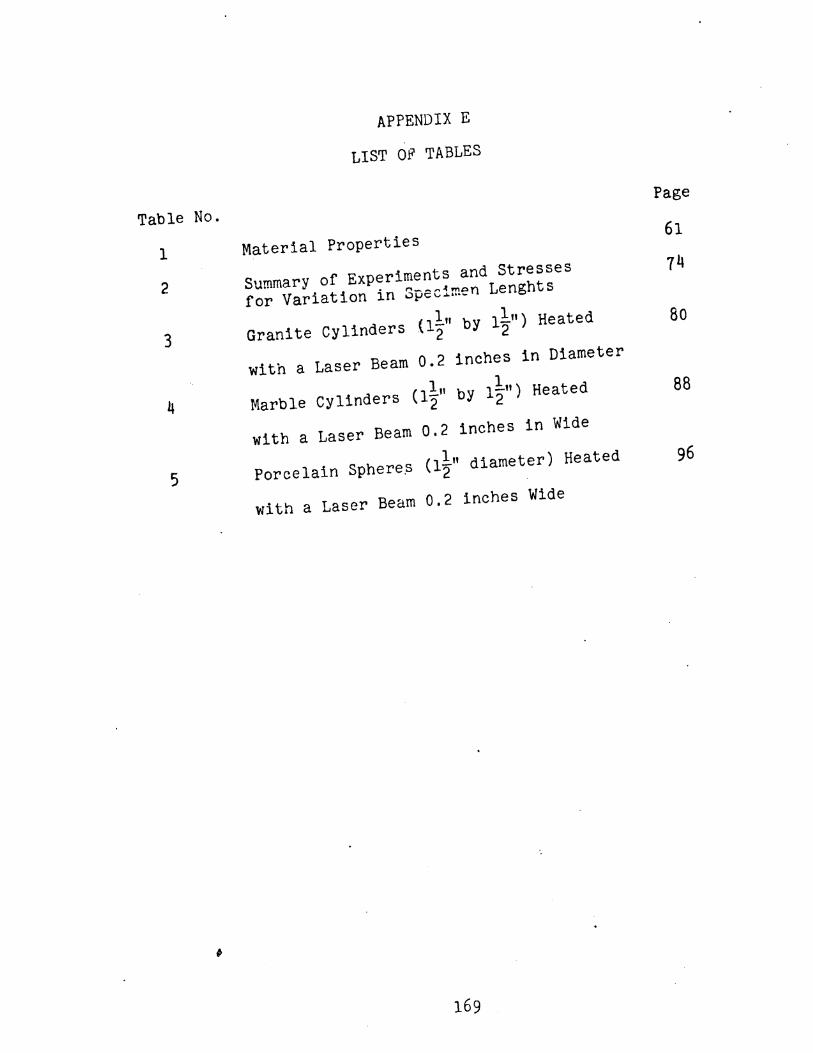
APPENDIX E
LIST OF TABLES
Table No.Page
1Material Properties
61
2Summary of Experiments and Stresses
14
for Variation in Specimen Lenghts
3 Granite Cylinders {l~" by l~") Heated 80
Iwith a Laser Beam 0.2 inches in Diameter
4(11"
1
Marble cylinders by 1"2") Heated 882
with a Laser Beam 0.2 inches in Wide
5 Porcelain Sphere~(1~" diameter) Heated 96
with a Laser Beam 0.2 inches Wide
169