Embed Size (px)
Citation preview
American Institute of Aeronautics and Astronautics
1
Investigation of Structure, Thermal Protection System, and Passenger Stage Integration for the Hypersonic Transport
System SpaceLiner
A. Kopp1 and N. Garbers 2 German Aerospace Center (DLR), Space Launcher Systems Analysis (SART), Bremen, 28359, Germany
The Space Launcher Systems Analysis Group SART of the German Aerospace Center DLR has been working for several years on developing a novel hypersonic passenger transportation concept. The SpaceLiner, originally proposed in 2005, is a two staged, rocket propelled and vertical take-off transportation system designed for a 90 minutes Europe-Australia reference mission carrying 50 passengers. In addition to the DLR internal activities, the SpaceLiner was also under investigation in the completed European Commission’s research project FAST20XX, and is one of the study vehicles in the current European CHATT project. A major challenge for the SpaceLiner is the design of a lightweight structure for this unique vehicle concept and the integration of structure and thermal protection system. For this task, a finite element based structural analysis tool will be used, allowing for rapid parametric studies for complex vehicle configurations with a high level of flexibility. This paper summarizes the current activities on the preliminary structural analysis for the SpaceLiner. Different materials and design options will be discussed, as well as the integration of structure and thermal protection system. A special focus will be placed on the design and the vehicle integration of the passenger rescue stage, which shall ensure a safe return of the passengers to ground in the case of a catastrophic failure of the vehicle.
Nomenclature AETB = Alumina Enhanced Thermal Barrier Tiles AFRSI = Advanced Flexible Reusable Insulation Al = Aluminum Al-Li = Aluminum-Lithium AoA = Angle of Attack APDL = ANSYS Parametric Design Language CFRP = Carbon Fiber Reinforced Plastic CHATT = Cryogenic Hypersonic Advanced Tank Technologies CMC = Ceramic Matrix Composite c.o.g. = Center of Gravity CRS = Crew Rescue Stage DLR = Deutsches Zentrum fuer Luft- und Raumfahrt (German Aerospace Center) E = Young’s Modulus EC = European Commission EF = Eigen-frequency FAST = Future High-Altitude High-Speed Transport FEA = Finite Element Analysis FRSI = Flexible Reusable Insulation GLOW = Gross Lift-Off Weight HySAP = Hypersonic Vehicle Structural Analysis Program 1 Research Scientist, Space Launcher Systems Analysis (SART), DLR, Robert Hooke Strasse 7, 28359 Bremen, Member of AIAA. 2 Research Scientist, Space Launcher Systems Analysis (SART), DLR, Robert Hooke Strasse 7, 28359 Bremen
American Institute of Aeronautics and Astronautics
2
LC = Load Case LH2 = Liquid Hydrogen LOX = Liquid Oxygen M = Mach number m = mass MECO = Main Engine Cut-Off MPC = Multi-Point-Constraint NOF = Non-Optimum Factor NOM = Non-Optimum Mass nx = acceleration in vehicle longitudinal direction nz = acceleration in vehicle normal direction qmax = Maximum Dynamic Pressure SART = Systemanalyse Raumtransport (Space Launcher Systems Analysis) TABI = Tailorable Advanced Blanket Insulation Ti = Titanium TNT = Trinitrotoluene TOP = TPS Optimization Program TPS = Thermal Protection System TUFI = Toughened Uni-Piece Fibrous Insulation ρ = Material Density σyield = Yield Stress
I. Introduction uborbital high speed transport is a technology that could significantly impact space transportation, since mass production of rocket propelled aircraft and their engines, as well as operating them on a routinely basis,
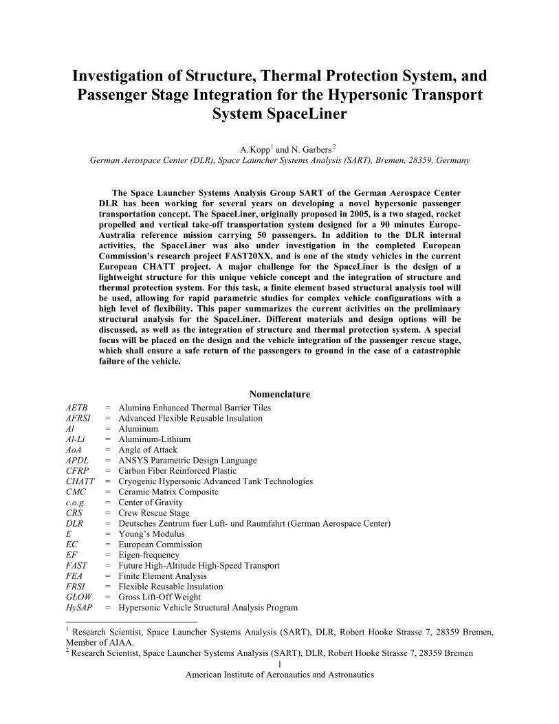
promises reductions in the manufacturing and launching costs for space launchers. With this vision in mind, the SpaceLiner concept was developed in the Space Launcher Systems Analysis group (SART) of DLR in 2005. Since then, the original design has evolved into several successive configurations. The latest configuration 7-2 is shown in Fig. 1. Currently, the configuration 7-3 is under definition. Various papers have been published about the SpaceLiner or its subsystems, for instance Ref. 1 and Ref. 2 as some of the latest ones. The SpaceLiner is a two staged, rocket propelled and vertical lift off passenger transport aircraft. The reference mission is to carry 50 passengers from Europe to Australia or vice versa within just 90 minutes. The SpaceLiner system is composed of a winged, passenger carrying main stage also denominated orbiter, and a winged booster. Both stages are liquid oxygen (LOX) and liquid hydrogen (LH2) propelled, and fully reusable. After booster separation, the orbiter continues the ascent with its own rocket engines until main engine cut-off (MECO) at an altitude of around 75 km. Subsequently, the range flight is being performed in gliding mode, whereas Mach numbers of up to 24 are reached.
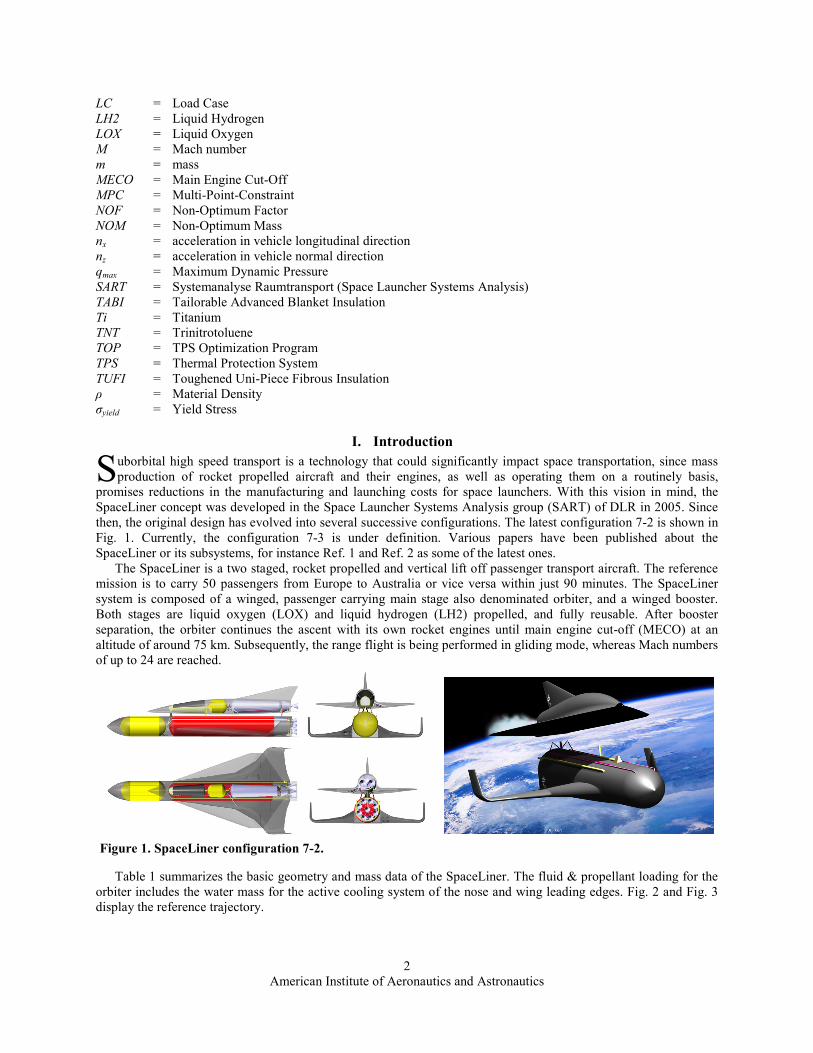
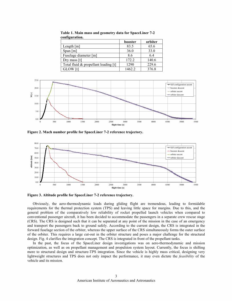
Table 1 summarizes the basic geometry and mass data of the SpaceLiner. The fluid & propellant loading for the orbiter includes the water mass for the active cooling system of the nose and wing leading edges. Fig. 2 and Fig. 3 display the reference trajectory.
S
Figure 1. SpaceLiner configuration 7-2.
American Institute of Aeronautics and Astronautics
3
0.0
5.0
10.0
15.0
20.0
25.0
0 500 1000 1500 2000 2500 3000 3500 4000 4500 5000 5500
M [-
]
flight time [s]
full configuration ascentbooster descentorbiter ascentorbiter descent
Figure 2. Mach number profile for SpaceLiner 7-2 reference trajectory.
0.0
10.0
20.0
30.0
40.0
50.0
60.0
70.0
80.0
0 500 1000 1500 2000 2500 3000 3500 4000 4500 5000 5500
altit
ude
[km
]
flight time [s]
full configuration ascentbooster descentorbiter ascentorbiter descent
Figure 3. Altitude profile for SpaceLiner 7-2 reference trajectory.
Obviously, the aero-thermodynamic loads during gliding flight are tremendous, leading to formidable
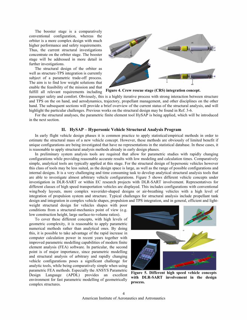
requirements for the thermal protection system (TPS) and leaving little space for margins. Due to this, and the general problem of the comparatively low reliability of rocket propelled launch vehicles when compared to conventional passenger aircraft, it has been decided to accommodate the passengers in a separate crew rescue stage (CRS). The CRS is designed such that it can be separated at any point of the mission in the case of an emergency and transport the passengers back to ground safely. According to the current design, the CRS is integrated in the forward fuselage section of the orbiter, whereas the upper surface of the CRS simultaneously forms the outer surface of the orbiter. This requires a large cut-out in the orbiter structure and poses a major challenge for the structural design. Fig. 4 clarifies the integration concept. The CRS is integrated in front of the propellant tanks.
In the past, the focus of the SpaceLiner design investigations was on aero-thermodynamic and mission optimization, as well as on propellant management and propulsion system layout. Currently, the focus is shifting more to structural design and structure-TPS integration. Since the vehicle is highly mass critical, designing very lightweight structures and TPS does not only impact the performance, it may even dictate the feasibility of the vehicle and its mission.
Table 1. Main mass and geometry data for SpaceLiner 7-2 configuration.
booster orbiter Length [m] 83.5 65.6 Span [m] 36.0 33.0 Fuselage diameter [m] 8.6 6.4 Dry mass [t] 172.2 140.6 Total fluid & propellant loading [t] 1290 229.6 GLOW [t] 1462.2 376.8
American Institute of Aeronautics and Astronautics
4
The booster stage is a comparatively conventional configuration, whereas the orbiter is a more complex design with much higher performance and safety requirements. Thus, the current structural investigations concentrate on the orbiter stage. The booster stage will be addressed in more detail in further investigations.
The structural design of the orbiter as well as structure-TPS integration is currently subject of a parametric trade-off process. The aim is to find low weight solutions that enable the feasibility of the mission and that fulfill all relevant requirements including passenger safety and comfort. Obviously, this is a highly iterative process with strong interaction between structure and TPS on the on hand, and aerodynamics, trajectory, propellant management, and other disciplines on the other hand. The subsequent sections will provide a brief overview of the current status of the structural analysis, and will highlight the particular challenges. Previous works on the structural design may be found in Ref. 3-6.
For the structural analyses, the parametric finite element tool HySAP is being applied, which will be introduced in the next section.
II. HySAP – Hypersonic Vehicle Structural Analysis Program In early flight vehicle design phases it is common practice to apply statistical/empirical methods in order to
estimate the structural mass of a new vehicle concept. However, these methods are obviously of limited benefit if unique configurations are being investigated that have no representations in the statistical database. In these cases, it is reasonable to apply structural analysis methods already in early design phases.
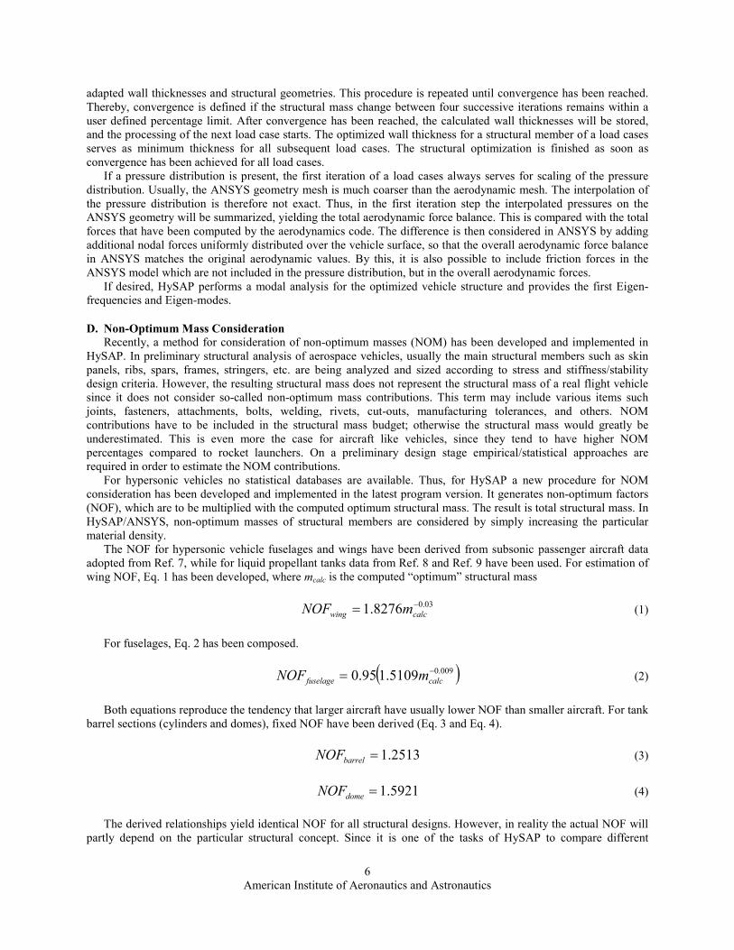
In preliminary system analysis tools are required that allow for parametric studies with rapidly changing configurations while providing reasonable accurate results with low modeling and calculation times. Comparatively simple, analytical tools are typically applied at this stage. For the structural design of hypersonic vehicles however this class of tools may be less suited, as the design space is large, as well as the range of possible configurations and internal designs. It is a very challenging and time consuming task to develop analytical structural analysis tools that are able to investigate almost arbitrary vehicle configurations. Figure 5 shows different vehicle concepts under investigation in DLR-SART or within EC research projects with DLR-SART involvement. Representatives for different classes of high speed transportation vehicles are displayed. This includes configurations with conventional wing/body layouts, more complex waverider-shaped designs or air-breathing vehicles with a high level of integration of propulsion system and structure. Typical challenges for structural analysis include propellant tank design and integration in complex vehicle shapes, propulsion and TPS integration, and in general, efficient and light-weight structural design for vehicles shapes with poor conditions from a structural-mechanics point of view (e.g. low construction height, large surface-to-volume ratios).
To cover these different concepts, with high levels of geometric complexity, it is reasonable to apply parametric numerical methods rather than analytical ones. By doing this, it is possible to take advantage of the rapid increase in computer calculation power in recent years together with improved parametric modelling capabilities of modern finite element analysis (FEA) software. In particular, the second point is of major importance, since parametric modelling and structural analysis of arbitrary and rapidly changing vehicle configurations poses a significant challenge for analytic tools, while being comparatively simple when using parametric FEA methods. Especially the ANSYS Parametric Design Language (APDL) provides an excellent environment for fast parametric modelling of geometrically complex structures.
Figure 4. Crew rescue stage (CRS) integration concept.
Figure 5. Different high speed vehicle concepts with DLR-SART involvement in the design process.
American Institute of Aeronautics and Astronautics
5
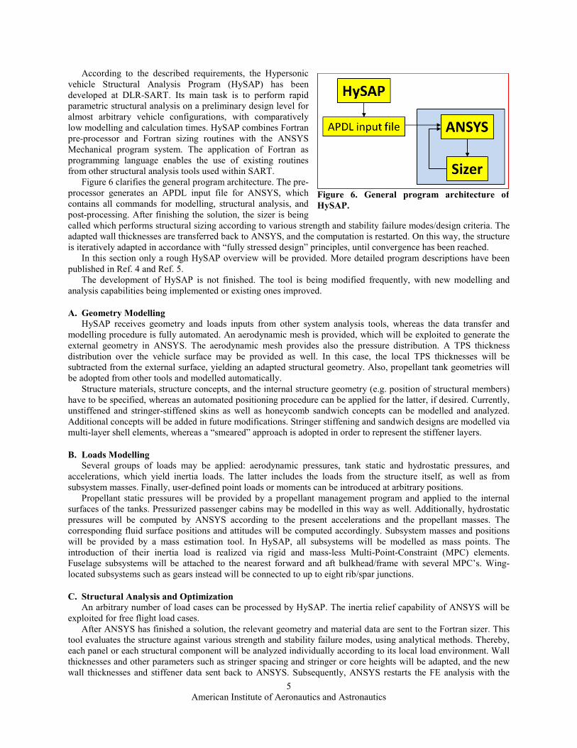
According to the described requirements, the Hypersonic vehicle Structural Analysis Program (HySAP) has been developed at DLR-SART. Its main task is to perform rapid parametric structural analysis on a preliminary design level for almost arbitrary vehicle configurations, with comparatively low modelling and calculation times. HySAP combines Fortran pre-processor and Fortran sizing routines with the ANSYS Mechanical program system. The application of Fortran as programming language enables the use of existing routines from other structural analysis tools used within SART.
Figure 6 clarifies the general program architecture. The pre-processor generates an APDL input file for ANSYS, which contains all commands for modelling, structural analysis, and post-processing. After finishing the solution, the sizer is being called which performs structural sizing according to various strength and stability failure modes/design criteria. The adapted wall thicknesses are transferred back to ANSYS, and the computation is restarted. On this way, the structure is iteratively adapted in accordance with “fully stressed design” principles, until convergence has been reached.
In this section only a rough HySAP overview will be provided. More detailed program descriptions have been published in Ref. 4 and Ref. 5.
The development of HySAP is not finished. The tool is being modified frequently, with new modelling and analysis capabilities being implemented or existing ones improved.
A. Geometry Modelling HySAP receives geometry and loads inputs from other system analysis tools, whereas the data transfer and
modelling procedure is fully automated. An aerodynamic mesh is provided, which will be exploited to generate the external geometry in ANSYS. The aerodynamic mesh provides also the pressure distribution. A TPS thickness distribution over the vehicle surface may be provided as well. In this case, the local TPS thicknesses will be subtracted from the external surface, yielding an adapted structural geometry. Also, propellant tank geometries will be adopted from other tools and modelled automatically.
Structure materials, structure concepts, and the internal structure geometry (e.g. position of structural members) have to be specified, whereas an automated positioning procedure can be applied for the latter, if desired. Currently, unstiffened and stringer-stiffened skins as well as honeycomb sandwich concepts can be modelled and analyzed. Additional concepts will be added in future modifications. Stringer stiffening and sandwich designs are modelled via multi-layer shell elements, whereas a “smeared” approach is adopted in order to represent the stiffener layers.
B. Loads Modelling Several groups of loads may be applied: aerodynamic pressures, tank static and hydrostatic pressures, and
accelerations, which yield inertia loads. The latter includes the loads from the structure itself, as well as from subsystem masses. Finally, user-defined point loads or moments can be introduced at arbitrary positions.
Propellant static pressures will be provided by a propellant management program and applied to the internal surfaces of the tanks. Pressurized passenger cabins may be modelled in this way as well. Additionally, hydrostatic pressures will be computed by ANSYS according to the present accelerations and the propellant masses. The corresponding fluid surface positions and attitudes will be computed accordingly. Subsystem masses and positions will be provided by a mass estimation tool. In HySAP, all subsystems will be modelled as mass points. The introduction of their inertia load is realized via rigid and mass-less Multi-Point-Constraint (MPC) elements. Fuselage subsystems will be attached to the nearest forward and aft bulkhead/frame with several MPC’s. Wing-located subsystems such as gears instead will be connected to up to eight rib/spar junctions.
C. Structural Analysis and Optimization An arbitrary number of load cases can be processed by HySAP. The inertia relief capability of ANSYS will be
exploited for free flight load cases. After ANSYS has finished a solution, the relevant geometry and material data are sent to the Fortran sizer. This
tool evaluates the structure against various strength and stability failure modes, using analytical methods. Thereby, each panel or each structural component will be analyzed individually according to its local load environment. Wall thicknesses and other parameters such as stringer spacing and stringer or core heights will be adapted, and the new wall thicknesses and stiffener data sent back to ANSYS. Subsequently, ANSYS restarts the FE analysis with the
Figure 6. General program architecture of HySAP.
American Institute of Aeronautics and Astronautics
6
adapted wall thicknesses and structural geometries. This procedure is repeated until convergence has been reached. Thereby, convergence is defined if the structural mass change between four successive iterations remains within a user defined percentage limit. After convergence has been reached, the calculated wall thicknesses will be stored, and the processing of the next load case starts. The optimized wall thickness for a structural member of a load cases serves as minimum thickness for all subsequent load cases. The structural optimization is finished as soon as convergence has been achieved for all load cases.
If a pressure distribution is present, the first iteration of a load cases always serves for scaling of the pressure distribution. Usually, the ANSYS geometry mesh is much coarser than the aerodynamic mesh. The interpolation of the pressure distribution is therefore not exact. Thus, in the first iteration step the interpolated pressures on the ANSYS geometry will be summarized, yielding the total aerodynamic force balance. This is compared with the total forces that have been computed by the aerodynamics code. The difference is then considered in ANSYS by adding additional nodal forces uniformly distributed over the vehicle surface, so that the overall aerodynamic force balance in ANSYS matches the original aerodynamic values. By this, it is also possible to include friction forces in the ANSYS model which are not included in the pressure distribution, but in the overall aerodynamic forces.
If desired, HySAP performs a modal analysis for the optimized vehicle structure and provides the first Eigen-frequencies and Eigen-modes.
D. Non-Optimum Mass Consideration Recently, a method for consideration of non-optimum masses (NOM) has been developed and implemented in
HySAP. In preliminary structural analysis of aerospace vehicles, usually the main structural members such as skin panels, ribs, spars, frames, stringers, etc. are being analyzed and sized according to stress and stiffness/stability design criteria. However, the resulting structural mass does not represent the structural mass of a real flight vehicle since it does not consider so-called non-optimum mass contributions. This term may include various items such joints, fasteners, attachments, bolts, welding, rivets, cut-outs, manufacturing tolerances, and others. NOM contributions have to be included in the structural mass budget; otherwise the structural mass would greatly be underestimated. This is even more the case for aircraft like vehicles, since they tend to have higher NOM percentages compared to rocket launchers. On a preliminary design stage empirical/statistical approaches are required in order to estimate the NOM contributions.
For hypersonic vehicles no statistical databases are available. Thus, for HySAP a new procedure for NOM consideration has been developed and implemented in the latest program version. It generates non-optimum factors (NOF), which are to be multiplied with the computed optimum structural mass. The result is total structural mass. In HySAP/ANSYS, non-optimum masses of structural members are considered by simply increasing the particular material density.
The NOF for hypersonic vehicle fuselages and wings have been derived from subsonic passenger aircraft data adopted from Ref. 7, while for liquid propellant tanks data from Ref. 8 and Ref. 9 have been used. For estimation of wing NOF, Eq. 1 has been developed, where mcalc is the computed “optimum” structural mass
03.08276.1 −= calcwing mNOF (1)
For fuselages, Eq. 2 has been composed.
( )009.05109.195.0 −= calcfuselage mNOF (2)
Both equations reproduce the tendency that larger aircraft have usually lower NOF than smaller aircraft. For tank barrel sections (cylinders and domes), fixed NOF have been derived (Eq. 3 and Eq. 4).
2513.1=barrelNOF (3)
5921.1=domeNOF (4)
The derived relationships yield identical NOF for all structural designs. However, in reality the actual NOF will partly depend on the particular structural concept. Since it is one of the tasks of HySAP to compare different
American Institute of Aeronautics and Astronautics
7
structural designs with each other, additional structural concept dependent NOF have been generated. The corresponding NOF have been developed with data from Ref. 10-13, and are listed in Table 2.
Table 2. Structural concept dependent NOF.
Panel concept NOFconcept Unstiffened skin 1.150 Stringer stiffened skin 1.150 Waffle grid 1.288 Sandwich honeycomb 1.366 Beaded 1.268 Tubular 1.248
For the final NOF it is assumed, that it is composed of a structural concept independent fraction (Eqs. 1-4), and a
concept dependent fraction (Table 2). Thereby, the NOF computed in Eqs. 1-4 are being divided by 1.15 (the panel dependent NOF for unstiffened/stringer stiffened panels) to yield a theoretic “basic” NOF. This basic NOF is then again multiplied with the concept dependent NOF as listed in Table 2. The final NOFfinal can then be computed by Eq. 5.
conceptbasicfinal NOFNOFNOF = (5)
NOF estimations have necessarily large inherent uncertainties, especially if no statistical database is available as it is the case for hypersonic transport vehicles. Thus, also the accuracy of the approach developed here is hardly predictable. In particular it has to be noted that so far only few datasets were available for derivation of both, the basic, as well as the structural concept based NOF. However, the presented methodology has the advantage that the vehicle size dependency as well the structural concept dependency is represented in tendency.
III. SpaceLiner Structural Analysis - Structural Model, Loads, and Assumptions Structural analyses for the SpaceLiner are subject of an ongoing parametric process with comparing different
design options with each other. Within this process, the applied tool chain is permanently modified in order to improve the modelling capabilities and the accuracy of the results. During these studies, the geometry model of the vehicle is still simplified. A more detailed model will be used as soon as the parametric investigations have yielded a consolidated structural configuration design.
A. Geometry Model The current vehicle model consists of a fuselage-wing combination with non-integral tanks. The wing is
designed as a conventional rib/spar/skin configuration, while the fuselage is stiffened by circumferential frames or bulkheads. In the present design, the bulkheads around the tanks are completely connected to the latter ones. Thus, the tanks support the fuselage with carrying the bending loads. This arrangement may be changed later to a design where the tanks carry their own loads only.
The internal structural members such as ribs, spars and frames/bulkheads can be broken down in two groups. The first group contains all members with fixed positions. This includes bulkheads at the tank cylinder beginning and ending positions, CRS supporting frames in the forward fuselage, as well as ribs and spars that enclose the main gear bay. A few more members are created automatically together with the mentioned members.
The second group contains additional ribs, spars and frames that are used to fill the voids between the fixed members. Their position and number may be varied in order to find low weight solutions. Fig. 7 shows the baseline internal architecture of the vehicle with fixed members only (left), and all members (right), respectively. Additional ribs and frames have been added by HySAP automatically. Thereby, the rib spacing was specified to be not higher than 2 m, and the spar spacing not higher than 4 m. The described design does not include CRS or main gear integration. These features will however be addressed in section V-C.

American Institute of Aeronautics and Astronautics
8
XY Z
WXWYWZXY Z
Figure 7. ANSYS geometry model (skins removed); fixed members only (left), all members (right).
In the baseline design, the fuselage utilizes stringer stiffened skins, although sandwich design might yield lower weights depending on the frame spacing.3 The wing instead has all members made of honeycomb sandwich, uniaxial stringer stiffening is not competitive here for this low aspect ratio wing. The fin has been neglected in the analysis since only symmetrical load cases are being considered.
B. Loads For preliminary trade-off studies it is common practice to identify only the most important load cases and size
the structure for them. Great care has to be taken when defining the order of load cases. Indeed, different orders may lead to different structural mass results. On the other hand, the computation time may be reduced significantly when selecting a dedicated load case order. For the trade-off analyses here, different orders were evaluated, but it was found that the load case order for this configuration has only a structural mass impact of around 1 %, which lies within the selected convergence tolerance (see section III-C). Thus, the order of load cases has been set such that the overall number of required iterations, and consecutively, the overall computation time is minimized.
Compared to the works as published in Ref. 3, the load case scheme has been revised here. Now, a total of three load cases (LC) are being considered. These are:
• LC1: nz = 2.5 g normal acceleration maneuver at qmax with downward flap deflection; empty tanks, 2 bars static tank pressure
• LC2: nz = 2.5 g normal acceleration maneuver at qmax with upward flap deflection; empty tanks, 2 bars static tank pressure
• LC3: Maximum axial acceleration during ascent; the orbiter is attached to the booster; partly filled tanks, 8.5 bars (LOX) and 2.5 bars (LH2) static tank pressure, respectively
The selection of nz = 2.5 g maneuver load cases correspond to the fulfillment of civil aviation requirements.14 For
load cases 1 and 2 flap deflections have been considered. Thereby, variable geometries are not foreseen in HySAP. Instead, the maximum flap forces have been computed before and then imposed to the rear section of the wing via an array of discrete forces in vehicle longitudinal and normal direction. Maximum flap deflections of +/- 35° have been assumed, although this is more a worst case scenario since for vehicle trimming usually lower flap deflections are sufficient. The angles of attack (AoA) in the aerodynamics code have then been adjusted such that the desired normal acceleration of nz = 2.5 g is achieved when the flap forces have already been applied. Consequently, different AoA have been used for generation of the pressure distribution in load cases 1 and 2 since the normal component of the flap deflection points in opposite directions. In both cases, the normal component of the flap deflection itself correspond to a normal acceleration of roughly +/- 0.5 g. For convenience reasons, the flap forces have been computed for 0° AoA. A more precise analysis would require an iterative approach in order to find the correct angle of attack and flap force combination that yield the desired 2.5 g. It should be noted, that during the HySAP optimization, the target value of nz = 2.5 g is only approximately achieved, since the total vehicle mass after optimization will not be identical to the mass that has originally been assumed for defining AoA and the corresponding pressure distribution computation. To be more precise, an iterative approach would be required again. However, the differences are usually small and can therefore be neglected. The axial accelerations for load cases 1 and 2 are in the nx = 0.45-0.50 g range.
In load case 3 the tanks are partly filled. The high static pressure in the LOX tank is the result of a booster-orbiter cross-feed system15. The static pressures are complemented by hydrostatic pressures that are computed by ANSYS during the HySAP optimization.
American Institute of Aeronautics and Astronautics
9
All considered subsystems including passenger cabin and payload are located in fuselage and wings at the appropriate positions.
C. Further Assumptions A safety factor of 1.5 has been applied to all strength and stability failure modes. The minimum gauge thickness
has been set to 0.5 mm. In earlier investigations a value of 0.25 mm had been used. This value was increased here in order to account for some uncertainties such as thermal loads or fatigue requirements. As shown in Ref. 3, the increase in minimum gauge thickness for this configuration from 0.25 mm to 0.5 mm results in a structural mass increase in the order of 5 %, depending on the structural material and the structural architecture.
The convergence tolerance has been set to 1.5 %. This means, that convergence is assumed to be reached as soon as the computed structural mass within 4 successive iterations does not change any more by more than 1.5 %.
IV. Design of the Thermal Protection System For the design of the thermal protection system the 1D sizing code TOP2 (TPS Optimization Program) has been
applied. Compared to the TPS mass results as presented in Ref. 3, a modified version of the tool with improved analysis methods has been used. The previous program version allowed thermal flux only in one direction: from the vehicle surface towards the interior. The modified tool allows heat flux in both directions. Indeed, this is of high importance for the later part of the trajectory, where the vehicle is flying with comparatively low Mach numbers and accordingly low thermal loads. Here, the heat amount still stored in the insulation from the high energy part of the trajectory, leads to higher temperatures in the insulation material than on the vehicle surface. Thus, a heat flux from insulation to the vehicle surface is present. Taking this effect into account, resulted in a significant reduction in TPS mass.
The TPS design as presented here considers only the reference trajectory of the vehicle. However, also mission abort trajectories have been defined for the orbiter. Previous investigations revealed that these abort trajectories yield higher thermal loads for some parts of the vehicle surface. Taking this into account would slightly increase the TPS mass compared to the results that are shown below.
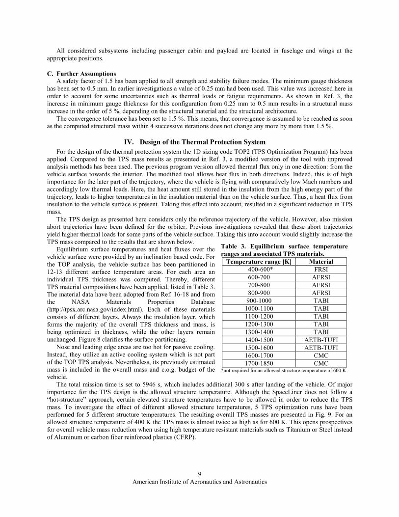
Equilibrium surface temperatures and heat fluxes over the vehicle surface were provided by an inclination based code. For the TOP analysis, the vehicle surface has been partitioned in 12-13 different surface temperature areas. For each area an individual TPS thickness was computed. Thereby, different TPS material compositions have been applied, listed in Table 3. The material data have been adopted from Ref. 16-18 and from the NASA Materials Properties Database (http://tpsx.arc.nasa.gov/index.html). Each of these materials consists of different layers. Always the insulation layer, which forms the majority of the overall TPS thickness and mass, is being optimized in thickness, while the other layers remain unchanged. Figure 8 clarifies the surface partitioning.
Nose and leading edge areas are too hot for passive cooling. Instead, they utilize an active cooling system which is not part of the TOP TPS analysis. Nevertheless, its previously estimated mass is included in the overall mass and c.o.g. budget of the vehicle.
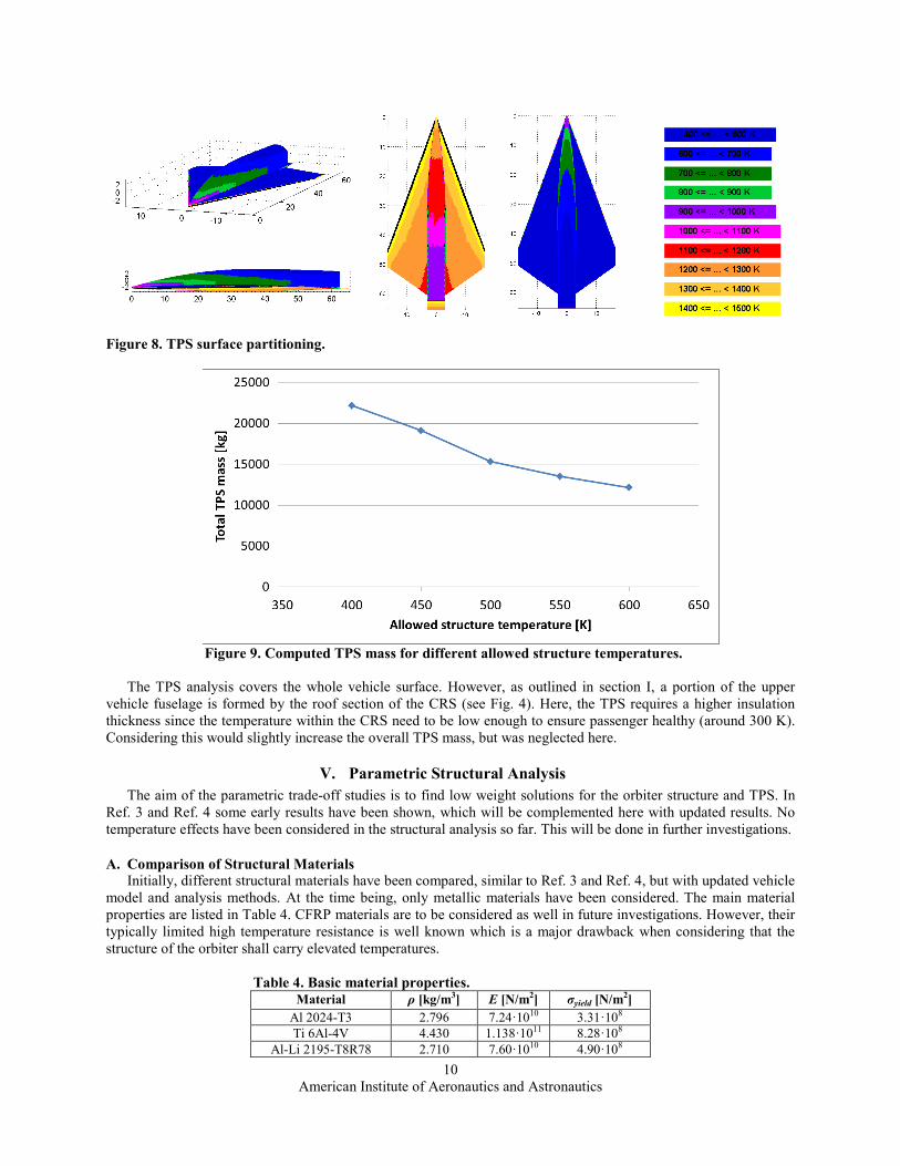
The total mission time is set to 5946 s, which includes additional 300 s after landing of the vehicle. Of major importance for the TPS design is the allowed structure temperature. Although the SpaceLiner does not follow a “hot-structure” approach, certain elevated structure temperatures have to be allowed in order to reduce the TPS mass. To investigate the effect of different allowed structure temperatures, 5 TPS optimization runs have been performed for 5 different structure temperatures. The resulting overall TPS masses are presented in Fig. 9. For an allowed structure temperature of 400 K the TPS mass is almost twice as high as for 600 K. This opens prospectives for overall vehicle mass reduction when using high temperature resistant materials such as Titanium or Steel instead of Aluminum or carbon fiber reinforced plastics (CFRP).
Table 3. Equilibrium surface temperature ranges and associated TPS materials.
Temperature range [K] Material 400-600* FRSI 600-700 AFRSI 700-800 AFRSI 800-900 AFRSI 900-1000 TABI
1000-1100 TABI 1100-1200 TABI 1200-1300 TABI 1300-1400 TABI 1400-1500 AETB-TUFI 1500-1600 AETB-TUFI 1600-1700 CMC 1700-1850 CMC
*not required for an allowed structure temperature of 600 K
American Institute of Aeronautics and Astronautics
10
Figure 8. TPS surface partitioning.
Figure 9. Computed TPS mass for different allowed structure temperatures.
The TPS analysis covers the whole vehicle surface. However, as outlined in section I, a portion of the upper
vehicle fuselage is formed by the roof section of the CRS (see Fig. 4). Here, the TPS requires a higher insulation thickness since the temperature within the CRS need to be low enough to ensure passenger healthy (around 300 K). Considering this would slightly increase the overall TPS mass, but was neglected here.
V. Parametric Structural Analysis The aim of the parametric trade-off studies is to find low weight solutions for the orbiter structure and TPS. In
Ref. 3 and Ref. 4 some early results have been shown, which will be complemented here with updated results. No temperature effects have been considered in the structural analysis so far. This will be done in further investigations.
A. Comparison of Structural Materials Initially, different structural materials have been compared, similar to Ref. 3 and Ref. 4, but with updated vehicle
model and analysis methods. At the time being, only metallic materials have been considered. The main material properties are listed in Table 4. CFRP materials are to be considered as well in future investigations. However, their typically limited high temperature resistance is well known which is a major drawback when considering that the structure of the orbiter shall carry elevated temperatures.
Table 4. Basic material properties.
Material ρ [kg/m3] E [N/m2] σyield [N/m2] Al 2024-T3 2.796 7.24·1010 3.31·108 Ti 6Al-4V 4.430 1.138·1011 8.28·108
Al-Li 2195-T8R78 2.710 7.60·1010 4.90·108
American Institute of Aeronautics and Astronautics
11
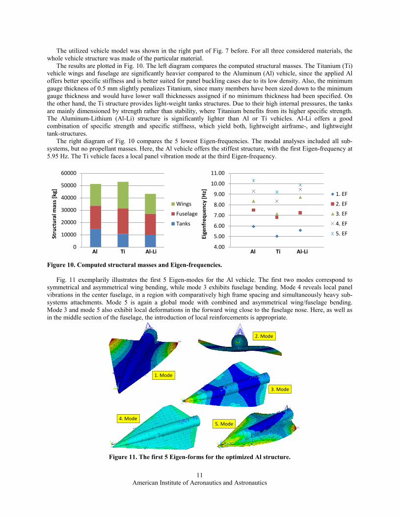
The utilized vehicle model was shown in the right part of Fig. 7 before. For all three considered materials, the whole vehicle structure was made of the particular material.
The results are plotted in Fig. 10. The left diagram compares the computed structural masses. The Titanium (Ti) vehicle wings and fuselage are significantly heavier compared to the Aluminum (Al) vehicle, since the applied Al offers better specific stiffness and is better suited for panel buckling cases due to its low density. Also, the minimum gauge thickness of 0.5 mm slightly penalizes Titanium, since many members have been sized down to the minimum gauge thickness and would have lower wall thicknesses assigned if no minimum thickness had been specified. On the other hand, the Ti structure provides light-weight tanks structures. Due to their high internal pressures, the tanks are mainly dimensioned by strength rather than stability, where Titanium benefits from its higher specific strength. The Aluminum-Lithium (Al-Li) structure is significantly lighter than Al or Ti vehicles. Al-Li offers a good combination of specific strength and specific stiffness, which yield both, lightweight airframe-, and lightweight tank-structures.
The right diagram of Fig. 10 compares the 5 lowest Eigen-frequencies. The modal analyses included all sub-systems, but no propellant masses. Here, the Al vehicle offers the stiffest structure, with the first Eigen-frequency at 5.95 Hz. The Ti vehicle faces a local panel vibration mode at the third Eigen-frequency.
0
10000
20000
30000
40000
50000
60000
Stru
ctur
al m
ass [
kg]
Al Ti Al-Li
Wings
Fuselage
Tanks
4.00
5.00
6.00
7.00
8.00
9.00
10.00
11.00
Eige
nfre
quen
cy [H
z]
Al Ti Al-Li
1. EF
2. EF
3. EF
4. EF
5. EF
Figure 10. Computed structural masses and Eigen-frequencies.
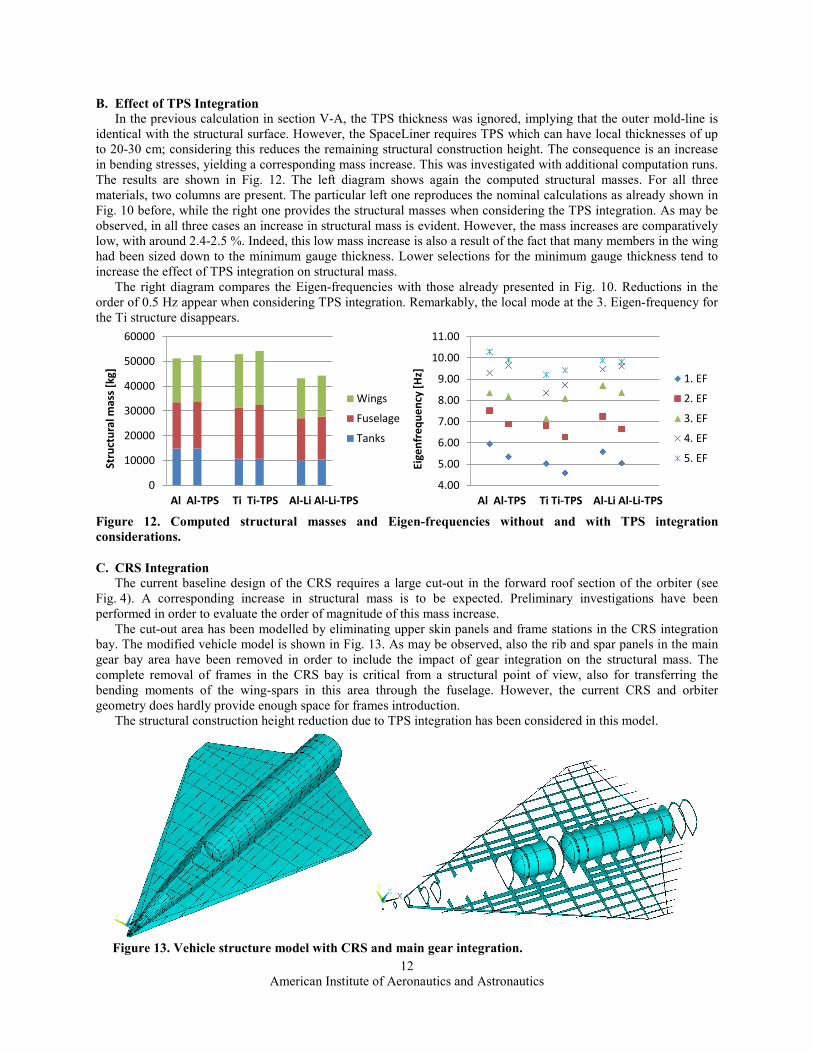
Fig. 11 exemplarily illustrates the first 5 Eigen-modes for the Al vehicle. The first two modes correspond to
symmetrical and asymmetrical wing bending, while mode 3 exhibits fuselage bending. Mode 4 reveals local panel vibrations in the center fuselage, in a region with comparatively high frame spacing and simultaneously heavy sub-systems attachments. Mode 5 is again a global mode with combined and asymmetrical wing/fuselage bending. Mode 3 and mode 5 also exhibit local deformations in the forward wing close to the fuselage nose. Here, as well as in the middle section of the fuselage, the introduction of local reinforcements is appropriate.
MN
MX
XYZ
MNMX
XY Z
UM (AVG)YS=0X =.014585X =.014585
MN
MX
XY
Z
MN
MX
XY
Z
MN
MX XY Z
(AVG)=0
=.033113 =.033113
1. Mode
2. Mode
3. Mode
4. Mode5. Mode
Figure 11. The first 5 Eigen-forms for the optimized Al structure.
American Institute of Aeronautics and Astronautics
12
B. Effect of TPS Integration In the previous calculation in section V-A, the TPS thickness was ignored, implying that the outer mold-line is
identical with the structural surface. However, the SpaceLiner requires TPS which can have local thicknesses of up to 20-30 cm; considering this reduces the remaining structural construction height. The consequence is an increase in bending stresses, yielding a corresponding mass increase. This was investigated with additional computation runs. The results are shown in Fig. 12. The left diagram shows again the computed structural masses. For all three materials, two columns are present. The particular left one reproduces the nominal calculations as already shown in Fig. 10 before, while the right one provides the structural masses when considering the TPS integration. As may be observed, in all three cases an increase in structural mass is evident. However, the mass increases are comparatively low, with around 2.4-2.5 %. Indeed, this low mass increase is also a result of the fact that many members in the wing had been sized down to the minimum gauge thickness. Lower selections for the minimum gauge thickness tend to increase the effect of TPS integration on structural mass.
The right diagram compares the Eigen-frequencies with those already presented in Fig. 10. Reductions in the order of 0.5 Hz appear when considering TPS integration. Remarkably, the local mode at the 3. Eigen-frequency for the Ti structure disappears.
0
10000
20000
30000
40000
50000
60000
Stru
ctur
al m
ass [
kg]
Al Al-TPS Ti Ti-TPS Al-Li Al-Li-TPS
Wings
Fuselage
Tanks
4.00
5.00
6.00
7.00
8.00
9.00
10.00
11.00
Eige
nfre
quen
cy [H
z]
Al Al-TPS Ti Ti-TPS Al-Li Al-Li-TPS
1. EF
2. EF
3. EF
4. EF
5. EF
Figure 12. Computed structural masses and Eigen-frequencies without and with TPS integration considerations.
C. CRS Integration The current baseline design of the CRS requires a large cut-out in the forward roof section of the orbiter (see
Fig. 4). A corresponding increase in structural mass is to be expected. Preliminary investigations have been performed in order to evaluate the order of magnitude of this mass increase.
The cut-out area has been modelled by eliminating upper skin panels and frame stations in the CRS integration bay. The modified vehicle model is shown in Fig. 13. As may be observed, also the rib and spar panels in the main gear bay area have been removed in order to include the impact of gear integration on the structural mass. The complete removal of frames in the CRS bay is critical from a structural point of view, also for transferring the bending moments of the wing-spars in this area through the fuselage. However, the current CRS and orbiter geometry does hardly provide enough space for frames introduction.
The structural construction height reduction due to TPS integration has been considered in this model.
XY Z
XY Z
Figure 13. Vehicle structure model with CRS and main gear integration.
American Institute of Aeronautics and Astronautics
13
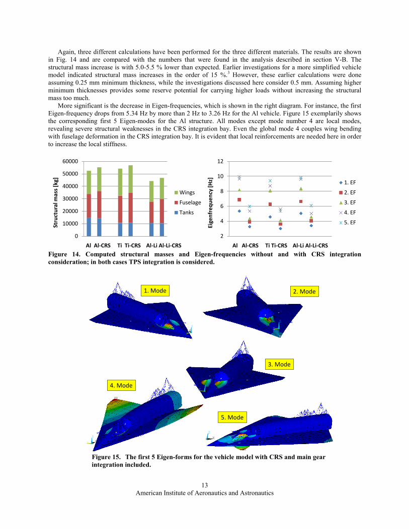
Again, three different calculations have been performed for the three different materials. The results are shown in Fig. 14 and are compared with the numbers that were found in the analysis described in section V-B. The structural mass increase is with 5.0-5.5 % lower than expected. Earlier investigations for a more simplified vehicle model indicated structural mass increases in the order of 15 %.3 However, these earlier calculations were done assuming 0.25 mm minimum thickness, while the investigations discussed here consider 0.5 mm. Assuming higher minimum thicknesses provides some reserve potential for carrying higher loads without increasing the structural mass too much.
More significant is the decrease in Eigen-frequencies, which is shown in the right diagram. For instance, the first Eigen-frequency drops from 5.34 Hz by more than 2 Hz to 3.26 Hz for the Al vehicle. Figure 15 exemplarily shows the corresponding first 5 Eigen-modes for the Al structure. All modes except mode number 4 are local modes, revealing severe structural weaknesses in the CRS integration bay. Even the global mode 4 couples wing bending with fuselage deformation in the CRS integration bay. It is evident that local reinforcements are needed here in order to increase the local stiffness.
0
10000
20000
30000
40000
50000
60000
Stru
ctur
al m
ass [
kg]
Al Al-CRS Ti Ti-CRS Al-Li Al-Li-CRS
Wings
Fuselage
Tanks
2
4
6
8
10
12
Eige
nfre
quen
cy [H
z]
Al Al-CRS Ti Ti-CRS Al-Li Al-Li-CRS
1. EF
2. EF
3. EF
4. EF
5. EF
Figure 14. Computed structural masses and Eigen-frequencies without and with CRS integration consideration; in both cases TPS integration is considered.
MN
MX
XYZ
MN
MX
XY
Z
MNMX
XY
Z
MN MX
XY
Z
MN MX
XY
Z
1. Mode 2. Mode
3. Mode
4. Mode
5. Mode
Figure 15. The first 5 Eigen-forms for the vehicle model with CRS and main gear integration included.
American Institute of Aeronautics and Astronautics
14
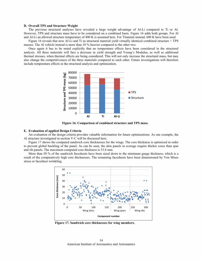
D. Overall TPS and Structure Weight The previous structural analyses have revealed a large weight advantage of Al-Li compared to Ti or Al.
However, TPS and structure mass have to be considered on a combined basis. Figure 16 adds both groups. For Al and Al-Li an allowed structure temperature of 400 K is assumed here. For Titanium instead, 600 K have been used.
Figure 16 reveals that now Al-Li and Ti as structural material yield virtually identical combined structure + TPS masses. The Al vehicle instead is more than 10 % heavier compared to the other two.
Once again it has to be noted explicitly that no temperature effects have been considered in the structural analysis. All three materials will face a decrease in yield strength and Young’s Modulus, as well as additional thermal stresses, when thermal effects are being considered. This will not only increase the structural mass, but may also change the competitiveness of the three materials compared to each other. Future investigations will therefore include temperature effects in the structural analysis and optimization.
01000020000300004000050000600007000080000
Stru
ctur
e an
d TP
S m
ass [
kg]
Al Ti Al-Li
TPS
Structure
Figure 16. Comparison of combined structure and TPS mass.
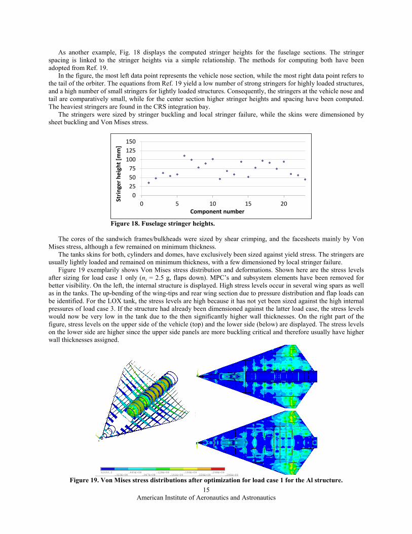
E. Evaluation of applied Design Criteria An evaluation of the design criteria provides valuable information for future optimizations. As one example, the
Al structure investigated in section V-C will be discussed here. Figure 17 shows the computed sandwich core thicknesses for the wings. The core thickness is optimized in order
to prevent global buckling of the panel. As can be seen, the skin panels in average require thicker cores than spar and rib panels. The maximum computed core thickness is 53.8 mm.
More than 50 % of the sandwich facesheets have been sized down to the minimum gauge thickness, which is a result of the comparatively high core thicknesses. The remaining facesheets have been dimensioned by Von Mises stress or facesheet wrinkling.
0
10
20
30
40
50
60
0 50 100 150 200 250 300
Core
thic
knes
s [m
m]
Component number
Wing skins Wing spars Wing ribs
Figure 17. Sandwich core thicknesses for wing members.
American Institute of Aeronautics and Astronautics
15
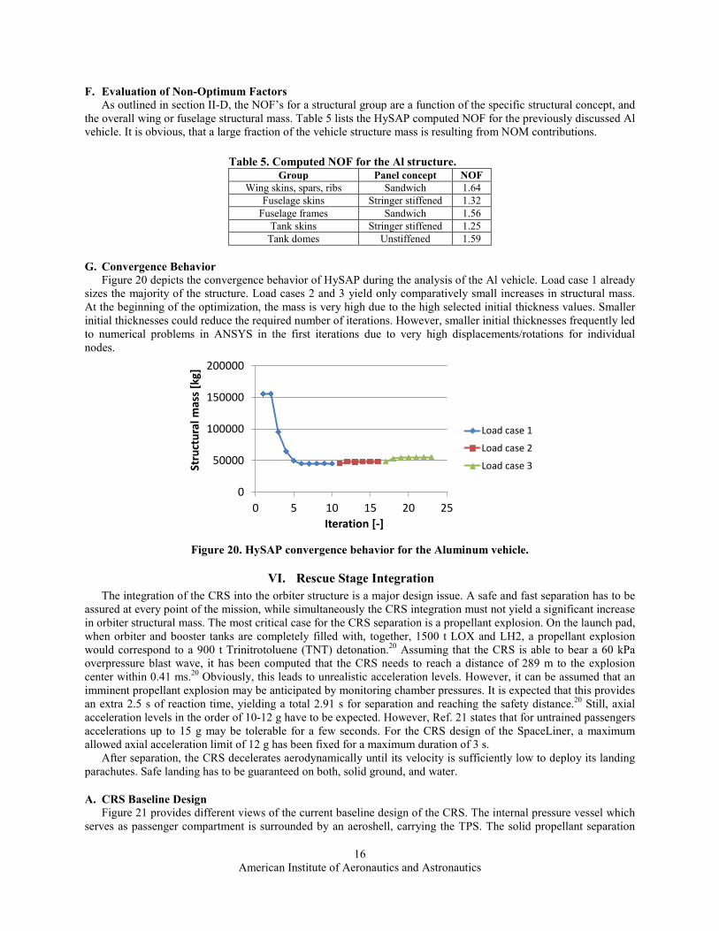
As another example, Fig. 18 displays the computed stringer heights for the fuselage sections. The stringer spacing is linked to the stringer heights via a simple relationship. The methods for computing both have been adopted from Ref. 19.
In the figure, the most left data point represents the vehicle nose section, while the most right data point refers to the tail of the orbiter. The equations from Ref. 19 yield a low number of strong stringers for highly loaded structures, and a high number of small stringers for lightly loaded structures. Consequently, the stringers at the vehicle nose and tail are comparatively small, while for the center section higher stringer heights and spacing have been computed. The heaviest stringers are found in the CRS integration bay.
The stringers were sized by stringer buckling and local stringer failure, while the skins were dimensioned by sheet buckling and Von Mises stress.
0255075
100125150
0 5 10 15 20Strin
ger h
eigh
t [m
m]
Component number
Figure 18. Fuselage stringer heights. The cores of the sandwich frames/bulkheads were sized by shear crimping, and the facesheets mainly by Von
Mises stress, although a few remained on minimum thickness. The tanks skins for both, cylinders and domes, have exclusively been sized against yield stress. The stringers are
usually lightly loaded and remained on minimum thickness, with a few dimensioned by local stringer failure. Figure 19 exemplarily shows Von Mises stress distribution and deformations. Shown here are the stress levels
after sizing for load case 1 only (nz = 2.5 g, flaps down). MPC’s and subsystem elements have been removed for better visibility. On the left, the internal structure is displayed. High stress levels occur in several wing spars as well as in the tanks. The up-bending of the wing-tips and rear wing section due to pressure distribution and flap loads can be identified. For the LOX tank, the stress levels are high because it has not yet been sized against the high internal pressures of load case 3. If the structure had already been dimensioned against the latter load case, the stress levels would now be very low in the tank due to the then significantly higher wall thicknesses. On the right part of the figure, stress levels on the upper side of the vehicle (top) and the lower side (below) are displayed. The stress levels on the lower side are higher since the upper side panels are more buckling critical and therefore usually have higher wall thicknesses assigned.
MN
MX
X
Y
Z
90E+09
MN
MX
X
Y
Z
71085 434.2 90E+09
MNMX
XY Z
52434.2
.323E+08.645E+08
.967E+08.129E+09
.161E+09.193E+09
.226E+09.258E+09
.290E+09
Figure 19. Von Mises stress distributions after optimization for load case 1 for the Al structure.
American Institute of Aeronautics and Astronautics
16
F. Evaluation of Non-Optimum Factors As outlined in section II-D, the NOF’s for a structural group are a function of the specific structural concept, and
the overall wing or fuselage structural mass. Table 5 lists the HySAP computed NOF for the previously discussed Al vehicle. It is obvious, that a large fraction of the vehicle structure mass is resulting from NOM contributions.
Table 5. Computed NOF for the Al structure.
Group Panel concept NOF Wing skins, spars, ribs Sandwich 1.64
Fuselage skins Stringer stiffened 1.32 Fuselage frames Sandwich 1.56
Tank skins Stringer stiffened 1.25 Tank domes Unstiffened 1.59
G. Convergence Behavior Figure 20 depicts the convergence behavior of HySAP during the analysis of the Al vehicle. Load case 1 already
sizes the majority of the structure. Load cases 2 and 3 yield only comparatively small increases in structural mass. At the beginning of the optimization, the mass is very high due to the high selected initial thickness values. Smaller initial thicknesses could reduce the required number of iterations. However, smaller initial thicknesses frequently led to numerical problems in ANSYS in the first iterations due to very high displacements/rotations for individual nodes.
0
50000
100000
150000
200000
0 5 10 15 20 25
Stru
ctur
al m
ass [
kg]
Iteration [-]
Load case 1
Load case 2
Load case 3
Figure 20. HySAP convergence behavior for the Aluminum vehicle.
VI. Rescue Stage Integration The integration of the CRS into the orbiter structure is a major design issue. A safe and fast separation has to be
assured at every point of the mission, while simultaneously the CRS integration must not yield a significant increase in orbiter structural mass. The most critical case for the CRS separation is a propellant explosion. On the launch pad, when orbiter and booster tanks are completely filled with, together, 1500 t LOX and LH2, a propellant explosion would correspond to a 900 t Trinitrotoluene (TNT) detonation.20 Assuming that the CRS is able to bear a 60 kPa overpressure blast wave, it has been computed that the CRS needs to reach a distance of 289 m to the explosion center within 0.41 ms.20 Obviously, this leads to unrealistic acceleration levels. However, it can be assumed that an imminent propellant explosion may be anticipated by monitoring chamber pressures. It is expected that this provides an extra 2.5 s of reaction time, yielding a total 2.91 s for separation and reaching the safety distance.20 Still, axial acceleration levels in the order of 10-12 g have to be expected. However, Ref. 21 states that for untrained passengers accelerations up to 15 g may be tolerable for a few seconds. For the CRS design of the SpaceLiner, a maximum allowed axial acceleration limit of 12 g has been fixed for a maximum duration of 3 s.
After separation, the CRS decelerates aerodynamically until its velocity is sufficiently low to deploy its landing parachutes. Safe landing has to be guaranteed on both, solid ground, and water.
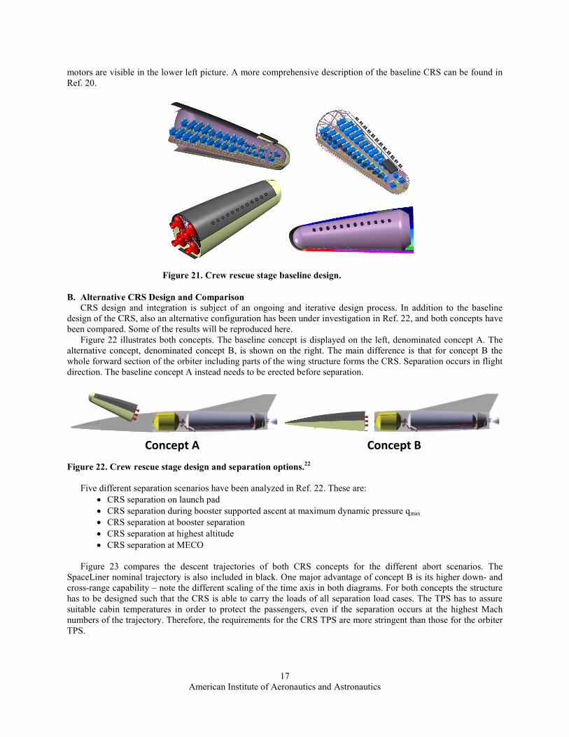
A. CRS Baseline Design Figure 21 provides different views of the current baseline design of the CRS. The internal pressure vessel which
serves as passenger compartment is surrounded by an aeroshell, carrying the TPS. The solid propellant separation
American Institute of Aeronautics and Astronautics
17
motors are visible in the lower left picture. A more comprehensive description of the baseline CRS can be found in Ref. 20.
Figure 21. Crew rescue stage baseline design.
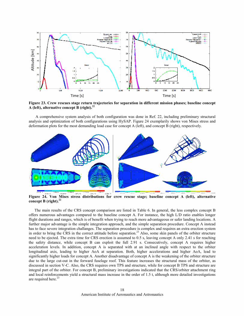
B. Alternative CRS Design and Comparison CRS design and integration is subject of an ongoing and iterative design process. In addition to the baseline
design of the CRS, also an alternative configuration has been under investigation in Ref. 22, and both concepts have been compared. Some of the results will be reproduced here.
Figure 22 illustrates both concepts. The baseline concept is displayed on the left, denominated concept A. The alternative concept, denominated concept B, is shown on the right. The main difference is that for concept B the whole forward section of the orbiter including parts of the wing structure forms the CRS. Separation occurs in flight direction. The baseline concept A instead needs to be erected before separation.
Concept A Concept B
Figure 22. Crew rescue stage design and separation options.22 Five different separation scenarios have been analyzed in Ref. 22. These are:
• CRS separation on launch pad • CRS separation during booster supported ascent at maximum dynamic pressure qmax • CRS separation at booster separation • CRS separation at highest altitude • CRS separation at MECO
Figure 23 compares the descent trajectories of both CRS concepts for the different abort scenarios. The
SpaceLiner nominal trajectory is also included in black. One major advantage of concept B is its higher down- and cross-range capability – note the different scaling of the time axis in both diagrams. For both concepts the structure has to be designed such that the CRS is able to carry the loads of all separation load cases. The TPS has to assure suitable cabin temperatures in order to protect the passengers, even if the separation occurs at the highest Mach numbers of the trajectory. Therefore, the requirements for the CRS TPS are more stringent than those for the orbiter TPS.
American Institute of Aeronautics and Astronautics
18
Time [s]Time [s]
Figure 23. Crew rescues stage return trajectories for separation in different mission phases; baseline concept A (left), alternative concept B (right).22
A comprehensive system analysis of both configuration was done in Ref. 22, including preliminary structural analysis and optimization of both configurations using HySAP. Figure 24 exemplarily shows von Mises stress and deformation plots for the most demanding load case for concept A (left), and concept B (right), respectively.
Figure 24. Von Mises stress distributions for crew rescue stage; baseline concept A (left), alternative concept B (right).22
The main results of the CRS concept comparison are listed in Table 6. In general, the less complex concept B
offers numerous advantages compared to the baseline concept A. For instance, the high L/D ratio enables longer flight durations and ranges, which is of benefit when trying to reach more advantageous or safer landing locations. A further major advantage is the simple integration approach, and the simple separation procedure. Concept A instead has to face severe integration challanges. The separation procedure is complex and requires an extra erection system in order to bring the CRS in the correct attitude before separation.23 Also, some skin panels of the orbiter structure need to be ejected. The extra time for CRS erection is assumed to 0.5 s, leaving concept A only 2.41 s for reaching the safety distance, while concept B can exploit the full 2.91 s. Consecutively, concept A requires higher acceleration levels. In addition, concept A is separated with at an inclined angle with respect to the orbiter longitudinal axis, leading to higher AoA at separation. Both, higher accelerations and higher AoA, lead to significantly higher loads for concept A. Another disadvantage of concept A is the weakening of the orbiter structure due to the large cut-out in the forward fuselage roof. This feature increases the structural mass of the orbiter, as discussed in section V-C. Also, the CRS requires own TPS and structure, while for concept B TPS and structure are integral part of the orbiter. For concept B, preliminary investigations indicated that the CRS/orbiter attachment ring and local reinforcements yield a structural mass increase in the order of 1.5 t, although more detailed investigations are required here.23

American Institute of Aeronautics and Astronautics
19
On the other hand, concept A also offers advantages. One is the significantly lower capsule mass, which for example enables smaller and lighter parachutes or separation rocket motors. The most important advantage of concept A is the impact protection of the CRS while being encapsulated in the orbiter, and the fail safe approach that is offered by the individual TPS and structure. For concept B this is a critical issue since a damage of the forward TPS of the orbiter, which could be one of the reasons for a CRS separation, is here simultaneously also a damage of the CRS TPS. Consequently, the CRS would fail to fulfil its main task of returning the passengers safely to earth. Table 6. Comparison of crew rescue stage concepts.
Concept A Concept B + Lower CRS mass + Simple integration + Impact protection + Faster separation - Extra time for erection + Lower loads - High AoA at separation + Higher L/D ratio - Higher loads + low AoA at separation - complex separation procedure - no impact protection - double TPS and structure - higher CRS mass - weakening of orbiter structure
A final decision on the concept down-selection can only be made, when the integration and separation concepts
have been worked out in detail. Also, further CRS variants are currently under conceptual investigation in addition to the two concepts described here.
VII. Conclusion and further Work This paper presented intermediate results of an ongoing parametric analysis for the structure and the TPS of the
SpaceLiner orbiter, as well as for the crew rescue stage design and integration. Further investigations results will be available and published soon.
The current investigations showed that the application of Aluminum-Lithium as structural material yields a vehicle structure that is about 15 % lighter compared to Aluminum, and almost 18 % lighter compared to Titanium. However, when considering thermal protection system and structure together, Aluminum-Lithium and Titanium yield virtually identical total masses. These preliminary results need to be complemented by the consideration of thermal effects in the structural analysis, what has been neglected so far. Furthermore, other structural materials need to be considered, in particular CFRP composites. Finally, also variations of structural member spacing and structural concepts will be analyzed.
The integration of the rescue stage into the orbiter structure was found to yield a structural mass increase in the order of 5-5.5 %. However, the stiffness of the structure significantly decreased and requires local reinforcements that will further increase the weight. An alternative design of the rescue stage was proposed and investigated. More detailed analyses will be done in the future, also taking into account other possible concepts for rescue stage design and integration.
Acknowledgments The authors gratefully acknowledge the contributions of Ms. Carola Bauer, Mr. Marcel Becker, and Mr. Johann
Mokstadt to the research on the SpaceLiner crew rescue stage. Furthermore, the authors would like to thank Mr. Björn Nagel and Mr. Pier Davide Ciampa. Their works on
parametric structural analysis provided valuable inputs for the development of HySAP.
References 1Sippel, M., Schwanekamp, T., Trivailo, O., Lentsch, A., “Progress of SpaceLiner Rocket-Powered High-Speed Concept”,
64th International Astronautical Congress, IAC-13-D2.4.05, Beijing, China, September 2013 2Sippel, M., Schwanekamp, T., Bauer, C., Garbers, N., Van Foreest, A., Tengzelius, U., Lentsch, A., “Technical Maturation
of the SpaceLiner Concept”, 18th AIAA International Space Planes and Hypersonic Systems and Technologies Conference, AIAA 2012-5850, Tours, France, September 2012
3Kopp, A., Garbers, N., “Structural and TPS Trade-Off Studies for the Hypersonic Transport System SpaceLiner”, 13th European Conference on Spacecraft Structures, Materials, and Environmental Testing, Braunschweig, Germany, April 2014
4Kopp, A., Garbers, N., Jarlas, R., Rabia, H., “Parametric Structural Analysis for the SpaceLiner”, 18th AIAA International Space Planes and Hypersonic Systems and Technologies Conference, AIAA 2012-5944, Tours, France, September 2012

American Institute of Aeronautics and Astronautics
20
5Kopp, A., “Parametric Studies for the Pre-Design of Hypersonic Aerospace Vehicles”, 12th European Conference on Spacecraft Structures, Materials, and Environmental Testing, Noordwijk, The Netherlands, March 2012
6Kopp, A., van Foreest, A., Sippel, M., Dalenbring, M., Jarlas, R., “Investigation of Structure for the Hypersonic Transport System SpaceLiner”, 17th AIAA International Space Planes and Hypersonic Systems and Technologies Conference, AIAA-2011-2373, San Francisco, April 2011
7Ardema, M. D., Chambers, M. C., Patron, A. P., Hahn, A. S., Miura, H., Moore, M. D., “Analytical Fuselage and Wing Weight Estimation of Transport Aircraft”, NASA-TM-110392, 1996
8Reitz, G. R., “The Derivation and Application of Nonoptimum Factors for Missiles and Spacecraft”, 26nd SAWE Annual Conference, Boston, USA, 1967
9Wu, K. C., Cerro, J. A., “Hardware-Based Non-Optimum Factors for Launch Vehicle Structural Design”, NSMMS - National Space and Missile Materials Symposium; Scottsdale, USA, 2010
10Plank, P. P., Sakata, I. F., Davis, G. W., Richie, C. C., “Hypersonic Cruise Vehicle Wing Structure Evaluation”, NASA-CR-1568, 1970
11Plank, P. P., Sakata, I. F., Davis, G. W., Richie, C. C., “Substantiation Data for Hypersonic Cruise Vehicle Wing Structure Evaluation, Volume 1-3”, NASA-CR-66897, 1970
12Martinovic, Z. N., “Structural Design and Analysis of Un-pressurized Cargo Delivery Vehicle”, 48th AIAA/ASME/ASCE/AHS/ASC Structures, Structural Dynamics, and Materials Conference, Waikiki, USA, 2007
13Martinovic, Z. N., “Shuttle Orbiter-like Cargo Carrier on Crew Launch Vehicle”, NASA-TM-2009-215793, 2009 14European Aviation Safety Agency, “Certification Specifications for Large Aeroplanes CS-25”, Amendment 2, October
2006 15Schwanekamp, T., Ludwig, C., Sippel, M., “Cryogenic Propellant Tank and Feedline Design Studies in the Framework of
the CHATT Project”,19th AIAA International Space Planes and Hypersonic Systems and Technologies Conference, Atlanta, USA, April 2014 (to be published)
16Williams, S. D., Curry, D. M., “Thermal Protection Materials”, NASA Reference Publication 1289, December 1992 17Glass, D. E., “Ceramic Matrix Composite (CMC) Thermal Protection Systems (TPS) and Hot Structures for Hypersonic
Vehicles”, 15th AIAA Space Planes and Hypersonic Systems and Technologies Conference, AIAA-2008-2682, Dayton, Ohio, April/May 2008
18Myers, D. E., Martin, C. J., Blosser, M.L., “Parametric Weight Comparison of Advanced Metallic, Ceramic Tile and Ceramic Blanket Thermal Protection System”, NASA/TM-2000-210289, June 2000
19Niu, M., “Airframe Structural Design: Practical Design Information and Data on Aircraft Structures”, Conmilit Press Ltd., Hongkong, 1997
20Bauer, C., Garbers, N., Johannsson, M., Lentsch, A., “Investigations of the SpaceLiner Passenger Capsule and Various Abort Scenarios”, Deutscher Luft- und Raumfahrtkongress, Berlin, Germany, September 2012
21Greensite, A. L., “Analysis and design of space vehicle flight control systems, Volume IXV - Abort”, NASA CR-835, 1969 22Becker, M., “Rettungskapsel-Design und Integration für das Hyperschallverkehrsflugzeug SpaceLiner”, DLR SART-
TN001/2014, Bremen, Germany, January 2014 23Mokstadt, J., “Untersuchung der Rettungskapsel-Separationsmechanismen für das Hyperschallverkehrsflugzeug
SpaceLiner”, DLR SART-TN010/2014, Bremen, Germany, March 2014