Embed Size (px)
Citation preview

CONTRACTOR REPORTSAND99-1477Unlimited ReleasePrinted June 1999
Investigation of Synergy BetweenElectrochemical Capacitors, Flywheels,and Batteries in Hybrid Energy Storage forPV Systems
John WohlgemuthSolarex630 Solarex CourtFrederick, MD 21703
Dr. John Miller Lewis B. SibleyJME, Inc. Tribology Systems, Inc.17210 Parkland Drive 239K Madison AvenueShaker Heights, OH 44120 Worminster, PA 18974
Prepared bySandia National LaboratoriesAlbuquerque, New Mexico 87185 and Livermore, California 94550
Sandia is a multlprogram laboratory operated by Sandia Corporation,a Lockheed Martin Company, for the United States Department ofEnergy under Contract DE-AC04-94AL85000.
Approved for public release; further dissemination is unlimited,
mSandia National laboratories

issued by Sandia National Laboratories, operated for the United StatesDepartment of Energy by Sandia Corporation.
NOTICE: This report was prepared as an account of work sponsored by anagency of the United States Government. Neither the United StatesGovernment, nor any agency thereof, nor any of their employees, nor any oftheir contractors, subcontractors, or their employees, make any warranty,express or implied, or assume any legal liability or responsibility for theaccuracy, completeness, or usefulness of any information, apparatus, product,or process disclosed, or represent that its use would not infringe privatelyowned rights. Reference herein to any specific commercial product, process, orservice by trade name, trademark, manufacturer, or otherwise, does notnecessarily constitute or imply its endorsement, recommendation, or favoringby the United States Government, any agency thereof, or any of theircontractors or subcontractors. The views and opinions expressed herein do notnecessarily state or reflect those of the United States Government, any agencythereof, or any of their contractors.
Printed in the United States of America. This report has been reproduceddirectly from the best available copy.
Available to DOE and DOE contractors fromOffIce of Scientific and Technical InformationP.O. BOX 62Oak Ridge, TN 37831
Prices available from (703 ) 605-6000Web site: http: flwww.ntis.govlordering. htm
Available to the public fromNational Technical Information ServiceU.S. Department of Commerce5285 Port Royal RdSpringtleld, VA 22161
NTIS price codesPrinted copy: A03Microfiche copy: A05
SAND99-1477Unlimited ReleasePrinted June 1999
Investigation of Synergy between Electrochemical Capacitors,Flywheels, and Batteries in Hybrid Energy Storage for PV
Systems
John WohlgemuthSolarex630 Solarex CourtFrederick, MD 21703
Dr. John MillerJME, Inc.17210 Parkland DriveShaker Heights, OH 44120
Lewis B. SibleyTribology Systerns, Inc.239K Madison AvenueWorminster, PA 18974
Abstract
This report describes the results of a study that investigated the synergy betweenelectrochemical capacitors (ECS) and flywheels, in combination with each otherand with batteries, as energy storage subsystems in photovoltaic (PV) systems.EC and flywheel technologies are described and the potential advantages anddisadvantages of each in PV energy storage subsystems are discussed. Sevenapplications for PV energy storage subsystems are described along with thepotential market for each of these applications. A spreadsheet model, which usedthe net present value method, was used to analyze and compare the costs overtime of various system configurations based on flywheel models. It appears that asynergistic relationship exists between ECS and flywheels. Further investigation isrecommended to quantify the performance and economic tradeoffs of this synergyand its effect on overall system costs.
The work described in this report was performed for Sandia National Laboratories underContract No. BD-0005C.

Intentionally left blank.

Acknowledgments
The authors would like to thank the Energy Storage Systems Program at Sandia NationalLaboratories and the Department of Energy’s Office of Power Technologies forsponsoring this work.
. ..111

Intentionally left blank.
iv
Contents
1. Preface ........................................................................................................................ 1
2. Introduction .................................................................................................................3
3. Storage Techologies ...................................................................................................53.1. Flywheels .............................................................................................................5
3.1.1. Advantages in PV System ...........................................................................73.1.1.1. Compatibility with Remote Sites .............................................................73.1.1.2. Longevity ................................................................................................73.1.1.3. Lack of Maintenance ...............................................................................8
3.1.1.4. Insensitivity to Deep Cycling ...................................................................93.1.1.5. Surge Capability ......................................................................................93.1.1.6. Tolerance of Ambient Temperature Extremes ........................................lO3.1.1.7. Lack of Environmental Impact ..............................................................lO
3.1.2. Disadvantages in PV Systems .....................................................................ll
3.1.2.1. Cost .......................................................................................................ll3.1.2.2. Reliability ..............................................................................................l33.1.2.3. Surge Capability .................................................................................... 13
3.2. Electrochemical Capacitors .................................................................................l33.2.1. Advantages in PV Systems ......................................................................... 15
3.2.1.1. Lack of Maintenance .............................................................................l53.2.1.2. Longevity ..............................................................................................l53.2.1.3. Environmentally Benign ........................................................................ 15
3.2.1.4. High Discharge Rate Capability .............................................................l53.2.2. Disadvantages in PV Systems .....................................................................l5
3.2.2 .l. Self.dischmge Rate ................................................................................l53.2.2.2. Cost .......................................................................................................l63.2.2.3. Output Voltage Control .........................................................................l7
3.3. Capacitorfiywhee~ atte~Combinations .........................................................l73.3.1. Flywheel/EC System .................................................................................l93.3.2. Battery/EC System ....................................................................................l9
4. Applications ..............................................................................................................2l4.1. Instrumentation/Highway Call Box .....................................................................22
4.2. Grid-independent Residential ..............................................................................224.3. Telecommunications ...........................................................................................224.4. Grid-connected Residential .................................................................................22
4.5. Electric Vehicle Charging Station ............................................................ ...........234.6. Grid-connected Commercial .................................................................... ...........234.7. T&D SUPPOrt ......................................................................................................23
5. Market halysis .........................................................................................................255.1. Net Present Value Analysis .................................................................................255.2. Potential Markets ................................................................................................25
5.2.1. Instrumentation/Highway Call Box ............................................................26
5.2.2. Grid-independent Residential .....................................................................275.2.3. Telecommunications ..................................................................................275.2.4. Grid-connected Residential .........................................................................285.2.5. EV Charging Stations ?8................................................................................. .
v

5.2.6. Grid-connected Comercial .......................................................................295.2.7. T&D Suppofi .............................................................................................29
5.3. Market Scale .......................................................................................................3O6. Conclusions ...............................................................................................................33
6.1. Flywheel Status ..................................................................................................336.2. Development of Low-cost ECS ...........................................................................336.3. Flywheel/Capacitor Synergy ...............................................................................33
7. Appendix A: Capacitor Manufacturers and Teckologies ...........................................358. Appendix B: Vendor Information ..............................................................................399. Appendix C: Net Present Value Analysis (Example) ..................................................4l
Figures
Figure 1. TSIBellcore flywheel . ......................................................................................6Figure 2. Ragone plot for P/Eratios of current flywheels . ................................................9Figure 3. U.S. power quality equipment market segments. * ...........................................3l
Tables
Table 1. TSI Flywheel Production and Development Cost Estimates ............................. 12Table 2. Characteristics of Flywheel Rotor Materials .....................................................l8Table 3. Application Categories for PV System ............................................................2lTable 4. Flywheel Market Projections Based onTSI Flywheels .....................................3OTable 5. Projected 5-year Annual Flywheel Market Size Based on TSI Flywheels.. .......30Table 6. Comparison of Near-term and 5-year EC Costs Based on TSI Flywheels .........31
vi
Acronyms and Abbreviations
ATTB
CMOS
DARPA
DOE
EC
EPRI
EV
HEB
HEV
NASA
NPV
NREL
PNGV
Pv
RFQ
T&D
TSI
UPS
VRLA
Advanced Technology Transit Bus
complementary metal-oxide semiconductor
Defense Advanced Research Projects Agency
U.S. Department of Energy
electrochemical capacitor
Electric Power Research Institute
electric vehicle
hybrid electric buses
hybrid electric vehicle
National Aeronautics and Space Administration
net present value
National Renewable Energy Laboratory
Partnership for a New Generation of Electric Vehicles
photovoltaics
request for quote
transmission and distribution
Tribology Systems, Inc.
uninterruptible power supply
valve-regulated lead-acid
vii

Intentionally left blank.
. . .VIII
1. Preface
The focus of this study was an investigation of the synergy between electrochemicalcapacitors (ECS) and flywheels in combination with each other and with batteries asenergy storage subsystems in photovoltaic (PV) systems. The focus was driven partly byeconomics; the high cost of available ECS precluded their use as direct replacements forlead-acid batteries in virtually all applications that require moderate to high energydensities. Thus, this study focused on how the unique capabilities of ECS (fast response,longevity, tolerance of temperature extremes, etc.) could justify their use in combinationwith other storage media. During the course of the study an emerging EC technology wasidentified that may be available at a cost low enough to challenge the initial high costassumptions for ECS. If the new technology delivers on its potential, both for energystorage and cost, ECS could become a viable replacement for lead-acid batteries in certainapplications.
1

Intentionally left blank.
2
2. Introduction
Sandia request for quote (RFQ) BD-0005 was directed at the first phase of a possiblemultiphase research project to identify user needs and application requirements forimproved integration of renewable energy generation technologies with energy storagesystems. In response to this RFQ, a team headed by Solarex proposed to investigate thefeasibility and potential of using ECS and flywheels, either singly or in combination, asenergy storage media in PV power systems.
Three-quarters of the PV systems deployed today use batteries as storage, despite the factthat in many of these systems batteries have known drawbacks, most notably:
. The poor life span match between batteries and PV. In a typical system, thebattery bank is replaced three or four times in the first 20 years of the PVarray’s life. Replacement is expensive, not just in purchase price, but intransportation and installation.
. The incompatibility of remote sites (common for PV systems) and batteries’maintenance requirements and weight.
. Their comparatively poor (approximately 50%-70%) energy efficiency in aPV system.
. The safety and environmental considerations, detailed later in this report.
These drawbacks illustrate the technology “gap” (in terms of the RFQ), where batterysystems do not truly meet the needs of existing applications and, additionally, have notbeen broadly adopted by emerging applications such as standby power and transmissionand distribution (T&D) support stations. This study looks at those systems as potentialapplications for new storage systems, and investigates the possibilityy of these new mediabroadening the applicability of PV power to applications not presently served.
Team member JME provided information on ECS and identified ESMA (a Russiancompany) as a possible source of low-cost “traction” capacitors. Team member TribologySystems, Inc. (TSI) provided information on flywheels and TSI flywheels were used asrepresentative models in this study. Preliminary analysis suggests a synergy between ECSand flywheels. ECS respond very quickly to changes in input and load, whichcomplements the low-loss storage capability of the flywheel. Both are virtuallymaintenance free, potentially expanding PV’s already significant penetration of theremote power market. Further, both are environmentally benign.
3

Intentionally lefl blank.
4

3. Storage Technologies
This section describes the energy storage technologies investigated with respect to theirgeneral characteristics as storage media in PV systems.
3.1. Flywheels
Flywheel development has been directed primarily at two areas: vehicular propulsionand storage as part of an electrical system. Flywheels are particularly compatible withelectric and hybrid electric vehicles (EVS and HEVS), where they can serve as aprimary storage medium or as a surge power source enabling enhanced vehicleacceleration and battery life. They are also compatible with the regenerative brakingsystems common to these vehicles. They have been investigated for vehicularpurposes since the late 1960s, when Oerlikon operated several buses in South Africautilizing flywheels as primary propulsion.
The technology advanced significantly with the development of carbon compositematerials for the rotor. Replacing steel, these materials provide more strength withless weight, and greatly reduce the risks previously associated with rotordisintegration. Various prototypes that employ composite rotors are presently in use,including one in a BMW demonstration vehicle. Another prototype is to be installedin an EV presently being tested at Hanscom Air Force Base in Massachusetts.
Flywheels are also being developed or are in prototype demonstration for severalmodes of use in electric systems.
. A flywheel manufactured by Trinity Flywheel of San Francisco is intended toprovide power smoothing, covering the variations in grid power that candisrupt sensitive equipment, and to provide short-term backup power in anoutage.
● Team member TSI provided a prototype, production-size flywheel (seeFigure 1) for telecommunications backup power to Bellcore. TSI palicipatedwith the regional Bell Telephone Operating Companies developing thegeneric requirements for back-up telecommunications power units tcl bepurchased for beta sites in the next few months and for widespreaddeployment next year. Prices for production quantities up to one millionannually have been quoted.
5

Figure 1. TSI Bellcore flywheel.
● TSI’s recent application to flywheels of solid-lubricated, hybrid-ceramicbearings and sliding surfaces greatly reduced flywheel cost in comparison todesigns that use magnetic bearings. This breakthrough evolved from TSItechnology and products developed over three decades. 1‘2>3These bearings areused not only in TSI’S own flywheels, but as primary or backup bearings inwheels made by United Technologies Corporation, including the units in theBMW and Air Force vehicles described above.
. Fifteen hybrid diesel-electric buses with flywheel storage and regenerativebraking have been in use in Europe since 1988.4 These magnet motor unitsstore 2 kwh with 150 kW peak output. The oldest of these buses has traveled180,000 km and its flywheel has achieved 250,000 cycles.
As these and other projects demonstrate, flywheels are much firther along thedevelopment curve than ECS, particularly those ECS used in a slow-dischargeenergy storage mode. With one exception (Russian “traction” capacitors), largecapacitors developed to date have focused primarily on fast power response, noton energy storage. The performance parameters and economics of ECS with thecharacteristics needed for energy storage in PV systems are basically unproven.
1Sibley, L.B., and Allen, C.M. “Friction and Wear Behavior of Refractory Materials at High SlidingVelocities and Temperatures,”Wear 5,312-320 (1962).2Taylor, K.M., Sibley, L.B., and Lawrence, J.C. “Development of a Ceramic Rolling-Contact Bearing forHigh-TemperatureUse,” Wear6 (3) 226-240(1963).3Sibley, L.B. “Silicon Nitride Bearing Elements for High-Speed High-Temperature Applications,” PaperNo. 5, NATO/AGARD Conference Proceedings No. 323 on Problems in Bearings and Lubrication ( 1982).4 Belanger, M. “Flywheels for Energy Storage Applications,” 6* International Seminar on Double LayerCapacitors and Similar Energy Storage Devices (1996).
6
3.1.1. Advantages in PV SystemsAdvantages and disadvantages of both flywheels and electrochemical capacitorsin PV systems are defined primarily by comparing them to the present storagestandard, the lead-acid battery. Although other batteries and other energy storagesystems, such as hydraulic storage, compressed air, and hydrogen generation areused in PV systems, the storage workhorse of PV systems is the lead-acid battery.
Much flywheel research has focused on use in vehicles and spacecraft, leading toan emphasis on minimizing the size and weight of the unit. Thus, much work hasbeen directed at high-speed (up to 90,000 rpm) units, which theoretically requiremagnetic bearings for longevity. This work has not been fully successful to date.
The size and weight constraints of the typical PV system are far less severe.While transportation is certainly a consideration for many sites, presentcomponents (e.g., batteries) are heavy and fairly large. Because the flywheel rotormay be heavier for such systems, rotational speed may be less, and such units arefarther along the development curve than high-speed wheels. The TSI wheel turnsat 30,000 rpm, and has demonstrated longevity and reliability using ceramicbearings. This wheel represents the state of the art for this technology and is usedas a representative flywheel in this report.
3.1.1.1. Compatibility with Remote SitesThe present, and to a greater extent, the projected characteristics of flywheelsmake them except ionally well-suited to the remote locations that are typical ofPV power systems. In part, this is because they share many of thecharacteristics of the PV module. These characteristics are discussed below.Flywheels are just beginning the prototype deployment stage in remote sites.Assuming the experience is favorable, it is probable that they will assume amajor energy storage role in remote power.
Lead-acid batteries are widely used but, because of their maintenance needsand replacement frequencies (every 2 to 7 years depending on variousfactors), are a poor fit to many remote power systems, especially whencompared to the PV component. Additionally, lead-acid batteries areexpensive to transport and install, use hazardous materials, can be damaged bymisuse or poor maintenance, and may generate hydrogen gas.
3.1.1.2. LongevityPerformance of prototype flywheels at TSI facilities and computer modelingsuggest a life expectancy for TSI flywheels longer than 20 years for mostapplications. One TSI unit has been in operation since the 1950s withoutrelubrication.5 Present fatigue design criteria are for 100,000 charge-dischargecycles per yearc, which, at one cycle per day, equates to a 274-year life span.The calculated L1O life (the period over which 10Yoof units would beexpected to fail) is 90 years.
5 Letters from Lewis B. Sibley of TSI to Bill Rever of Solarex. July 28, 1998 and May 5, 1999.GSibley, Lewis B. “Advanced Technology Ceramic Bearings in the Flywheel Systems at World FlywheelConsortium.” Presented at the Flywheel Energy Storage Workshop, Oak Ridge, TN. 1995.
7
The L1O life is calculated using the equation:
L = alxa,~~(C/P)3
Where al is 1 (indicates “very clean” operating conditions) for 90%reliability, C is the basic dynamic load rating for each bearing size (based onthe manufacturer’s specifications), P is the equivalent load on the bearing inservice, a~mis 37 (calculated from manufacturer’s specifications). Therefore,
L=37x40~
or 2,368 billion revolutions. At a typical 50,000-rpm continuous mean rotorspeed,
L = 2368x 10’ /(50000x60x8760)
or 90.1 years. In comparison, the batteries of a PV system require replacementat least three times, and as frequently as six times (depending on severity ofcycling and thermal stresses) over what PV designers have considered thenominal lifespan of a PV systern-20 years.
As experience with deplo yed PV systems has accumulated, major modulemanufacturers have gained confidence in the ability of their products toexceed this lifespan. Siemens recently extended the warranty period on theirlarge modules to 25 years. Solarex has introduced a new series of largemodules, the GSX series, with a 30-year warranty.
Furthermore, the failure mechanisms of deployed PV modules are, in general,either “infant y“ failures or long-term gradual output degradation, which is nota true “failure,” although it may eventually cause inability to support the load.After infancy, modules are likely to function effectively for at least 30 years.As the PV industry has matured, the causes of infancy failures (thermalcycling of interconnects, material incompatibility y, water migration, etc.) havebeen identified and corrected, and the failure rate has been dramaticallyreduced.
It is appropriate, therefore, to consider a lifespan longer than 20 years for PVsystems and their components. Most of the comparisons in this report arebased on a 30-year system life.
3.1.1.3. Lack of MaintenanceFor all intents and purposes, the TSI flywheel is maintenance free as a resultof its hybrid ceramic bearings and solid lubrications ystem. Alternativebearing systems are either very expensive (magnetic bearings) or incompatiblewith operation in a vacuum. Conventional bearings require periodiclubrication, typically with volatile petroleum-based lubricants thatcontaminate the vacuum.
In contrast, lead-acid batteries require inspection and terminal cleaning andsome require watering between two and twelve times a year, depending oncycling and thermal climate.
8

3.1.1.4. Insensitivity to Deep CyclingEven the best deep-cycle batteries suffer from shortened lifetimes if they arecycled beyond their specified depth-of-discharge limit, or are cycledfrequently. These limitations force system owners and designers to trade offreliability against cost, either by using an oversized battery to ensurecontinuous power to the load or by including a low-voltage disconnect circuitthat protects the battery but sacrifices the load.
Repeated overdischarge is catastrophic to a lead-acid battery, but flywheelsare unaffected by it, both structurally and in terms of longevity and regardlessof discharge frequency. This characteristic frees the system designer from thecostly sizing/disconnect consideration above.
3.1.1.5. Surge CapabilityThe ability to respond to demand surges can be both a positive and a negativecharacteristic of a flywheel, depending on the design of the flywheel, theduration of the surge, and the criticality of the load’s power requirement.Figure 2 illustrates the specific power vs. specific energy (P/E ratio) of anumber of current flywheel designs, and the characteristic durationsassociated with the P/E ratios.
,’;’ l! .+’
,,,.’ ‘~;’ ,; + University of Texas ,,..’,/’,i’ ,.,’,,. i
,/;! ,.. ~
Pl,k 100...
,...,,;’ (,* sac) b
P/Ek200 P1EJ50 ..-’[
(1! aec) ;’ ,,,(72 aec)- /“’ !
.,-’””””-’ ,!; / ....
,,.’f. ,., ..-””-’
,,,... P1.EIK% ~1;J ,.,“’ ,.~.,
.,.’” .,< ,....--fia =) !!/ ,,f ,..’ -,-’-,,. [/. ,.,.’ .--’j ,,.’ ,+ .,-’”-’
,i’ ,.,”’ .....”’/~ ,.,.-’ /-”””, .... I,/ ..,”) /“
,----,, “~World Flywheel Consorjiurfi”-”...- 1
,( ~’ {... ...’’-’-~agne~~tor ,.,’””
(TSI),,--- f
/ .,-’-. -...-.-.-”
.,’ .,.,.. . .,..-’
jP&AO--’---”””” ;
,’ b .,., ● Unique Motility’.”’j ,“.’ .-....---”-.-’”””””@60 eec)
!; / .,. ,./..’ -.-...-.---’-””-,.4’
,,.. ,------ i,,;’ ,,” /- ~--------- 1/ / F1’Gketdyn.e--_””
-------/. --------. ........,/ “;’ ,,’ ,, -.-
.,.. /-● .lJni@YIGhnologies
American!.’,./’ ,,,,., ...-’. ..-----” I,. ,.-. FtywtIaal,’ ,J’ _,----:,. ./ .-’ -...’--’-
!,. ,’....’-.”....~...-. Bellcore (TSl) Systems ● ~:,.:..,/-,------ ● ~
0 5 10 15 20 25 30 35 40
Specific Energy (Wh/kg)
Figure 2. Ragone plot for P/E ratios of current flywheels.
The flywheel’s characteristic duration—the minimum period in which adevice can deliver approximately 63% (the 1-l/e value) of its capacity to a
9
load7—varies from approximately 18 seconds for a wheel with a P/E ratio of200 to approximately 360 seconds for a wheel with a P/E ratio of 10. Somestorage media are less efficient for surge (high power) requirements shorterthan approximately 5 times their characteristic duration.
As Figure 2 shows, most development work has concentrated on flywheelscapable of fast response, a characteristic necessary for vehicular applicationsand any other application where the wheel must cope with a load that mayvary rapidly. It does not illustrate the characteristics of wheels that could bedesigned specifically for PV systems, which could have durations on the orderof an hour and P/E ratios well below 10. Such wheels, and the lower P/Ewheels. illustrated, could not respond well to short-term demand peaks,particularly if the peaks required good power regulation.
Although PV battery banks generally have the ability to meet demand surges,if the surge is sufficiently large and repeated it will shorten the life of thebattery bank. In systems that anticipate such surges, adding a fast-responseflywheel or a capacitor to the power system may improve overall powerquality and extend battery life.
3.1.1.6. Tolerance of Ambient Temperature ExtremesWith solid lubricant, TSI flywheels are unaffected by any terrestrial ambienttemperature, in terms of efficienc y, longevity, and storage capacit y.g
Battery capacity and life is typically optimized for, and rated at an operatingtemperature of 25”C, and a significant variation from that temperaturecompromises operating life or storage capacity. Manufacturers’ literatureindicates that a battery’s rated life is reduced by half if it is operatedcontinuously at 35°C, and that batteries fail very quickly if operated above50”C. Battery capacity is reduced by approximately half (from rating) at O°C.
A discharged battery may be destroyed by subfreezing temperatures. At 80%depth of discharge battery electrolyte freezes at –1 O°C, resulting in permanentdamage to the plates and case. A fi.dly discharged battery freezes at onlyslightly below O“C.
3.1.1.7, Lack of Environmental ImpactBatteries use hazardous materials—among them lead, sulfuric acid, andcadmium-and thus present environmental concerns that must be addressedduring their manufacture, use, and disposal. The materials used in flywheelshave less environmental impact.
Safety concerns about containment of flywheel components in case ofcatastrophic failure have been addressed by several projects and studies, themost recent being a Defense Advanced Research Projects Agency (DARPA)
7 Note: Not all flywheel developers use 63% as the cutoff level for energy extraction. Varying thispercentage will affect the flywheel’s spin down time.8 Sibley, L.B. “Silicon Nitride Bearing Elements for High-Speed High-Temperature Applications,” PaperNo. 5, NATO/AGARD Conference Proceedings No. 323 on Problems in Bearings and Lubrication (1982).
10
project that included extensive analysis in conjunction with the NationalRenewable Energy Laboratory (NREL).9
The high kinetic energy of a bursting flywheel is expressed almost entirely ashigh circumferential rubbing speeds when fragments centrifugally impact thecontainment housing. The containment system of the TSI flywheel used in thisstudy is based on multiple burst tests (in all of which the rotor was completelycontained) and advanced computerized testing. 10Additionally, in many PVapplications the flywheel can be buried, which provides redundant protectionin case of flywheel failure.
3.1.2. Disadvantages in PV SystemsA flywheel’s disadvantages in a PV system are few but significant: cost and thedevelopment status of the technology. Substantial progress has been made sincethe 1960s, but current designs have yet to undergo the ultimate test of long-termdeployment. Experience with PV systems indicates the potential for presentlyunidentified remote-site problems with the flywheel itself and the electronics thatcontrol power input and output.
3.1.2.1. CostTeam member TSI configured four representative flywheel models in varioussizes to meet the requirements of the specified systems. As with batteries,these units would be used in multiples to provide the exact amount of energystorage required for a specific system.
Table 1 shows the development costs and several production volume andtiming assumptions for each of the representative models. These costs arebased on TSI’S knowledge of the economics of flywheel development andvolume production costs associated with TSI’S own flywheel technology. Thecomparisons between storage technologies are not adjusted for inflation orother time effects. The production volume figures are fairly aggressiveestimates of total annual volume for all markets, not just those associated withPV. This report addresses life-cycle issues, inflation, and other time effectsusing the net present value (NPV) method described in Section 5.1.
9 Sibley, L.B. “Design Optimization and Proof Testing of Safety Containment Systems for FlywheelEnergy Storage Systems,” Final Report on Subrecipient Agreement No. MARCAV 9602-12 of DARPAContract MDA 972-95-3-0019 (1998).10Sibley, L.B. “Design Optimization and Proof Testing of Safety Containment Systems for FtywheelEnergy Storage Systems,” Final Report on Subrecipient Agreement No. MARCAV 9602-12 of DARPAContract MDA 972-95-3-0019 (1998).
11

Table 1. TSI Flywheel Production and Development Cost Estimates
The smallest unit (0.5 kWh) requires little development and could be ready forproduction in less than 1 year, with an initial cost, assuming production of50,000-80,000 units per year, of $2200. Under the 10-year, high-volume (3 to5 million annually) assumption, these units are projected to cost $500 or lesseach, equating to $1000 per kWh.
The largest models (25 and 200 kWh) require substantial development work,estimated at 12 to 18 months; thus, no 1-year production figures are given forthem. As would be expected, the largest unit, the 200-kWh model, is projectedto provide the least expensive storage—$275 per kwh under the 10-year,high-volume assumption. Under the l-year production case, the smallest unit(0.5 kwh) provides the most expensive storage at $4400 per kwh.
In comparison, high-quality lead-acid batteries cost approximately $100 to$120 per kwh. They may not, however, be fully discharged withoutshortening their usable life. Assuming 5090 of their nominal capacity is used,their effective cost increases to $200 to $240 per kwh. Thus, using the10-year production models, the projected cost of flywheel storage ranges froma high of five times as much as batteries to almost equal to that of batteries. Inthe short term (1 year), flywheel storage is much more expensive, up to20 times more expensive for the smallest units.
These storage costs are based on TSI’S estimates for production units, notprototypes. The pilot production units will be substantially more expensivethan production units due to material volume considerations and the cost ofcustom machining and other labor-intensive production steps. These costs arereflected in the First Unit Cost entries in Table 1.
12
3.1.2.2. ReliabilityAlthough, as described above, calculations of predicted flywheel lifetimes areimpressive and supplement laboratory and prototype experience, long-termremote deployment is the ultimate test. The PV industry knows fromexperience that deployment tests the system as a system, in situations wherefailure of one component means total system failure.
In particular, the flywheel’s control electronics require field testing. The rigorsof remote-site systems— lightning, animal damage, substandardtransportation, marginal installation, etc.-can wreak havoc on PV controlsystems that appear bulletproof on the design board.
3.1.2.3. Surge CapabilityAs previously mentioned, wheels designed specifically for PV systems (andany wheel with slow characteristic response time) cannot respond well toshort-term demand peaks if the peaks require good power regulation.Although the flywheel has sufficient energy to meet the peak, its controlelectronics must respond almost instantaneously to some loads (e.g.,computers) to maintain nominal operation.
In addition to response time and power quality considerations, a flywheel’selectrical response is limited by the size of its power-handling conductors.Motor-generator windings must be sized to handle surge requirements, whichcould be impractical for some loads. Additionally, the heat generated by anycomponent inside the containment vessel presents a dissipation requirement.For these reasons, an EC may be a worthwhile addition to many remote powerstorage systems, particularly those which could have substantial surgerequirements.
3.2. Electrochemical Capacitors
ECS have achieved substantial acceptance in the electronics industry, replacingbackup batteries in many complementary metal-oxide semiconductor (CMOS)memory applications. Many commercially available ECS are directed at this market,and, consequently, are of limited size and power performance. These limitations arenot inherent in the technology but rather due to the market forces that have clriven thedesign. Much larger, higher-voltage capacitors with greatly enhanced powerperformance have been available for several years from some suppliers and currentlyare being developed by others. These ECS are directed at new markets, among themautomotive starting, lighting, and ignition circuits and, in Russia, vehicle motivepower.
One early Russian application of ECS was for starting vehicles in cold climates. InSiberia, the cold-weather advantages of ECS over chemical batteries were quicklyapparent. In addition, the Russian fwm ESMA now has over two years’ experienceusing ECS as the sole energy source for forklifts, electric trucks, and buses. TheRussians are presently operating six 1.5-ton trucks, three buses, two street-sweepers,and twenty forklifts with ECS serving as the motive batteries. Additional details of
13
their experience are described in “New Ultracapacitors Developed by JSC ESMA forVarious Applications.”] *
Major automotive manufacturers have been developing EVS to meet zero emissionvehicle requirements. Domestic manufacturers have also been developing HEVSthrough sponsorship by the federal government under the “Partnership for a NewGeneration of Vehicles” (PNGV). In addition, transit bus manufacturers haveprograms to develop hybrid-electric buses (HEBs). One such program is theAdvanced Technology Transit Bus or ATTB being developed by Northrup GrummanCorporation.
High-energy-density capacitors have been identified as an enabling technology formany of these low-pollution applications, and recent development efforts havefocused primarily on EC technology. ECS appear well suited for such applicationsbecause they offer high volumetric capacitance density. This advantage is derivedfrom the use of high-surface-area electrodes to create a large “plate area” and fromstoring energy in the so-called diffuse double layer. This double layer, creatednaturally at a solid/electrolyte interface when voltage is imposed, has a thickness ofonly approximately 1 n~ forming an extremely thin “plate separation. ”Consequently, ECS with very high capacitance density can be made using high-surface-area electrodes. Some ECS show enhanced capacitance derived frompseudocapacitance charge storage in addition to double layer charging. One Russiancompany manufactures an asymmetric EC having energy density greater than10 Wh/kg.
Compared to batteries, ECS have longer cycle life and higher rate capabilit y, butlower energy density. They require a much simpler charging circuit than a battery,and display no “memory effect .“ Physical, rather than chemical, energy storage is thekey reason for the EC’s cycle life and its high power density compared to othercapacitors. Furthermore, ECS have the potential to meet important cost targetsbecause their electrodes typically consist of relatively low-cost material, for example,activated carbon derived from wood or coal.
Significant advances have been made in the development of large capacitors duringthe past decade, stimulated by Isuzu’s 1990 development of a “revolutionary newbattery. ” Some investigations have focused on using ECS to level the load on energystorage systems in electric and gas-electric hybrid vehicles, reducing stress on thechemical batteries and extending their life. Other development activities, fimdedprimarily by the U.S. Department of Energy (DOE), have been directed at startinginternal combustion engines, electrically preheating exhaust catalytic converters,powering uninterruptible power supplies (UPSS), and other automotive applications.
Most of these applications require large capacitors capable of delivering a substantialfraction of their stored energy in a few seconds. This power performance requirementis a major departure from the established computer memory backup applications,where discharge times are typically hours or days. These design drivers are similar to
]1Varakin, I.N., Klementov, A.Il., L~tvinenko, S.V., Staroduvtsev, N.F., Stepanov, A.B. “NewUltracapacitors Developed by JSC ESMA for Various Applications,” 8* International Seminar on DoubleLayer Capacitors and Similar Energy Storage Devices (1998).
14

energy system drivers where an EC would meet power surges, but very different fromsystem drivers where an EC would be the primary energy storage medium.
Team member JME used published data, correspondence, and discussions withdevelopers and manufacturers to compile a summary of products and technologies ofvarious vendors (see Appendix A). Manufacturers’ addresses are included asAppendix B.
3.2.1. Advantages in PV SystemsElectrochemical capacitors have significant advantages for deployment in PVsystems, particularly in remote settings.
3.2.1.1. Lack of MaintenanceIn contrast to the battery maintenance requirements described previously,capacitors require no maintenance. The financial and systemic ramificationsof this are enormous, greatly reducing system cost over time and allowing thestorage system to be located in places impractical for chemical batterysystems (e.g., buried).
3.2.1.2. LongevityBecause capacitors store charge physically rather than chemically, cycling hasvirtually no effect on their capacity or longevity. The lifetime of mostcapacitors is limited by electrolyte loss. Twenty-year life is easily achieved byproper selection of materials and control of operating parameters. It isanticipated that thirty-year life is also achievable, although this will requiredevelopment and may increase product cost.
3.2.1.3. Environmentally BenignCapacitors do not employ toxic materials, and thus present no environmentalthreat in manufacture, transport, or disposal. They do not outgass in use andpresent no threat of explosion.
3.2.1.4. High Discharge Rate CapabilityCapacitors can be discharged at very high rates without damage. High rates,however, reduce the delivered energy of the unit.
3.2.2. Disadvantages in PV Systems
3.2.2.1. Self-discharge RateThe self-discharge rate of most capacitors is substantially higher than that ofbatteries or flywheels. This limits their application in grid-independentsettings to systems with multiple storage media capable of offsetting this self-discharge. In grid-connected systems, where they could serve to attenuatedrastic demand swings, self-discharge is not a major consideration.
Team member JME indicates that the self-discharge of the ESMA EC is lowerthan that of any other capacitor type. It is expected to take 8 months todischarge to 50% of capacity. This is very similar to the rate for someshallow-cycle batteries, which can lose up to 6% per month to self-discharge.(Good deep-cycle batteries are substantially better.)
15

Battery self-discharge is usually of little consequence in PV system sizingbecause its magnitude is small enough to be hidden in procedures necessary toaccount for solar variation. If self-discharge in ECS proves to be high,however, it would have to be compensated for in system sizing procedures,and should be quantified in any further investigations.
3.2.2.2. CostJME’s original estimates of the cost of appropriate EC storage for PVapplications were in the range of $10 to $20 per kJ, or $10,000 to $20,000per MJ, based on extrapolating current EC costs to higher production levelswith modest technological advances. At this price, between 12 and 30 timesthat of batteries, capacitors appeared unattractive in economic terms,particularly as straight replacements for batteries, despite the favorablecharacteristics discussed above.
However, during the course of this study, major Russian f~ms that specializein manufacturing large ECS were asked to provide price estimates based onmodifying typical EC design drivers (power delivery and response time) todrivers compatible with stand-alone PV systems, greatly reducing the need forvolume power and elirninat ing the requirement of fast response.
ESMA’S response, quoted below, cut projected purchase cost to 50 cents perkJ. The NPV analysis (discussed in Section 5.1), which includes such factorsas the cost of periodic battery servicing and replacement, indicates that acapacitor selling at this price would provide storage at about three times thecost of batteries.
ESMA states:
Given certain relaxed constraints as per your information, we mayconcentrate on “traction” capacitor technologies. These technologies allow[us] to ensure lower prices per 1 kJ of energy. flcompared to prices forbatteries (per your information – U.S. $120 per 1 kwh), the pinnacle of ourdesires today with respect to “traction” capacitors is about U.S. $1700-1800per 1 kWh (which corresponds to U.S. cents 47-50 per 1 H). Again, theforegoing levels may be reached only in case of large-scale batch productionand under cheaper electrode production technologies. These prices arecurrently several times higher.
This projection is preliminary, and is subject to all the technical and economicuncertainties that affect a technology as new as ESMA’s. While the Russianexperience is promising, there are many steps between ESMA’s currentproduct status and the deployment of ECS as a component in a cost-effective,reliable PV power system. These steps include developing a less costlyelectrode production method, scaling up production significantly, prototyping,and field testing.
Additionally, the volatility of the present Russian economy and currencymake this cost projection less certain than if it had been offered by a f~mlocated elsewhere. However, regardless of the country of origin, the offerrepresents the state of the art in large traction ECS today. If ESMA does not
16

apply its knowledge to producing PV-compatible ECS in Russia, fwms in othercountries probably will.
3.2.2.3. Output Voltage ControlAlthough the output of a PV device is well-suited to charging a capacitor,capacitor discharge characteristics are significantly different than lead-acidbattery discharge characteristics. Battery voltage drops slowly under load untila substantial portion of the battery’s usable energy has been extracted. In atypical PV application, battery voltage drops about 11% as 90% of its energyis extracted.
Extracting 75?i0 of a battery’s energy produces a voltage drop of 7 to 8Y0.Incontrast, extracting 75920of an EC’s energy produces an approximately 5090voltage drop. The consequence is a broad voltage swing, which severely limitsthe applications to which ECS may be applied without power conditioning.
Many present PV applications require no power conditioning or voltagelimiting. These loads tolerate the voltage swings of the battery as it chargesand discharges. A virtue of such systems is their simplicity—with no circuitrybetween the battery and the load other than a high-reliability switch (usedprimarily to protect the battery from deep discharge) their failure modes arelimited. In fact, some critical systems have no active element between thebattery and the load, valuing load support above battery longevity.
Virtually all traditional PV applications would require power conditioningbetween the output of an EC and the load, either a DC/DC converter for DCloads or an inverter for AC loads. This requirement adds to system cost andreduces system efficiency and reliabilityy.
The corollary to the voltage range of a discharging capacitor is its availableenergy. Although discharging an EC below 509i0 of its rated voltage does notharm its structure, for most applications additional discharge is impractical.Thus a capacitor’s available energy is typically only 75% of its rating.
3.3. Capacitor/Flywheel/Battery Combinations
Quantifying the efficacy of flywheels and ECS as storage media in PV systems isdifficult. Although the EC’s energy storage capability has been known for a century,no real market existed until the development of low-current-draw volatile computermemory circuits. Most development and commercialization effort has focused on thismarket and on improving the device’s response speed and short- and mid-term energystorage characteristics. With the exception of recent Russian efforts, little has beendirected at optimizing ECS for the characteristics important to PV systems,particularly efficient long-term energy storage.
The little development that has been done in this area indicates that ECS not only canbe substantially improved for this purpose, but that their cost per joule can be reducedsubstantially in the process. Cost reductions can be effected because of reduced laborand inherent efficiencies of scale. Further, per joule, long-term storage requires moreof the EC’s active elements (primarily carbon) and less of the inactive elements(i.e., packaging, separators, current collectors, interconnect bus sizes, etc.), which aregenerally more expensive than the active elements.
17
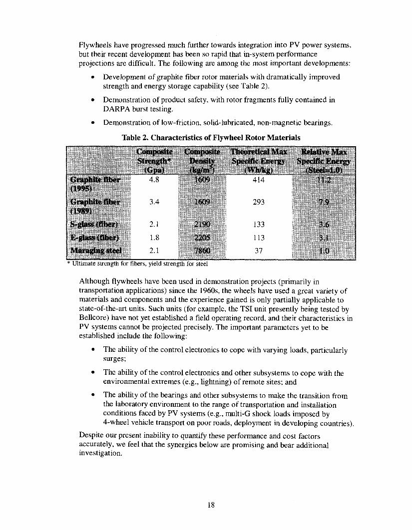
Flywheels have progressed much further towards integration into PV power systems,but their recent development has been so rapid that in-system performanceprojections are difficult. The following are among the most important developments:
● Development of graphite fiber rotor materials with dramatically improvedstrength and energy storage capability (see Table 2).
. Demonstration of product safety, with rotor fragments fully contained inDARPA burst testing.
. Demonstration of low-friction, solid-lubricated, non-magnetic bearings.
Table 2. Characteristics of Flywheel Rotor Materials
* Uttimate strength for fibers, yield strength for steel
Although flywheels have been used in demonstration projects (primarily intransportation applications) since the 1960s, the wheels have used a great variety ofmaterials and components and the experience gained is only partially applicable tostate-of-the-art units. Such units (for example, the TSI unit presently being tested byBellcore) have not yet established a field operating record, and their characteristics inPV systems cannot be projected precisely. The important parameters yet to beestablished include the following:
. The ability of the control electronics to cope with varying loads, particularlysurges;
. The ability of the control electronics and other subsystems to cope with theenvironmental extremes (e.g., lightning) of remote sites; and
. The ability of the bearings and other subsystems to make the transition fromthe laboratory environment to the range of transportation and installationconditions faced by PV systems (e.g., multi-G shock loads imposed by4-wheel vehicle transport on poor roads, deployment in developing countries),
Despite our present inability to quantify these performance and cost factorsaccurately, we feel that the synergies below are promising and bear additionalinvestigate ion.
18
3.3.1. F1ywheel/EC SystemsAlthough flywheels respond quickly to demand, their characteristic response timeis longer than an EC’s, which can cope with the millisecond-level responserequired by such applications as UPSS. The motor-generators of many existingflywheel systems, including those manufactured by TSI, use an electrolyticcapacitor for starting and to smooth transients. Replacing this capacitor with ahigh-capacity electrochemical unit could, in addition to the electrolytic’s function,
. greatly improve the system’s abilit y to respond to demand surges andsimultaneously relax the design requirements for the mechanicalcomponents of the flywheel system; and
. extend the unit’s life substantially. Present electrolytic capacitors last,at best, 10 years. ECS can be made for 20- or 30-year lifetimes, a spancompatible with the demonstrated life of PV arrays and the expectedlife of flywheels.
3.3.2. Battery/EC SystemsBatteries have the ability to provide extremely high power levels on demand.Although most PV applications make no use of this characteristic, other batteryapplications do. One such application is telephone substations, which use. largebatteries to maintain service during utility power outages. These batteries arecycled infrequently, but heavily, and must cope with large surge requirements.They display short lifetimes, sometimes as short as one year.
These substations are one example of grid-supplemental systems, which includesthe category of UPS systems. UPSS vary tremendously in size, from units servingindividual computers to systems supporting vital circuits in large buildings orbuilding complexes. By definition, these systems must respond instantly to poweroutages, and often rely on battery banks to bridge the period between loss of gridpower and delivery of backup power from their fuel-powered generators. These“bridge” batteries are severely cycled, subjected to heavy surge demands, and areshort-lived.
Electrochemical capacitors paralleled with these battery banks could respondquickly to bridge power needs, cope with the transients generated during sourcechangeover, absorb demand surges that would otherwise stress the batteries, andgreatly extend battery life.
19

Intentionally left blank.
20

4. Applications
The analysis of applications began with the identification of seven application categoriesthat are either established or emerging markets for PV systems with conventional energystorage. The examples range tremendously in scale, from systems with 5-W arrays tosystems with 1-MW arrays.
These applications are summarized in Table 3. The first four applications are small-tomid-size systems with well-established markets. The last three applications are larger andaddress markets that can be characterized as rapidly developing. Although numerousexamples of grid-connected commercial and transmission and distribution (T&D) supportsystems exist, most are prototypes or are supported by corporate or governmentdevelopment programs.
This section discusses the application categories and the system sizes necessary to meettheir requirements. Example system configurations, based on the representative flywheelsizes discussed in Section 3.1.2.1, and consisting of a PV array, a flywheel or multipleflywheels, and an electrochemical capacitor attached to each flywheel are provided forreference. The ECS in these example systems would provide limited energy storage tocope with transients, provide fast response to demand surges, and maintain power quality.These ECS are sized to provide up to half of the load’s peak demand for three seconds.This capacity is sufficient to support a significant surge in a stand-alone PV system. As apoint of reference, the Electric Power Research Institute (EPRI) reports thatapproximately 92% of line “voltage sag” events last three seconds or less. 12
While we highly recommend further investigation into the role of ECS as a primaryenergy storage medium, we do not have sufficient data at present to configure them, evenconceptually, as a system’s sole energy storage device.
Table 3. Application Categories for PV Systems
12 V; Max 100W
Max 200 W
Continuous 25-500 W, Max: 1 kW
5 kW
50 kW-100 kW
Continuous same asPV array Max:300 kW--l MW
Continuous same asPV array; Max:500 kW--2MW
5-100 kwh
5-30 kwh
l-2Mwh
0.2-2 m
2Mwh
-40”C-60”C
-1oOc-400c
-25°C-400C
loO-3@c
Ambient
Conditioned
Ambient
loowyr
1Ooolyr
loruyr
1oo/yT
50/yr
1Ofyr
I
12EPRI Distribution Power Quality Report #RP3098-01.
21
4.1. Instrumentation/Highway Call Box
This group represents a number of small PV applications. These are applicationswhere a small amount of power is needed for small electronic devices such asinstruments, sensors, data loggers, radio telemetry transceivers, or cellular phones.These applications typically require from 5 to 50 Wh per day, which can be generatedby 5 to 30 Wp of PV.
System configuration example: One 0.5-kWh flywheel and a 2.4-kJ EC.
4.2. Grid-independent Residential
Systems of this scale can be remote vacation-type cabins or homes in developingcountries and developing sections of the U.S. and other industrial countries. Suchsystems have been deployed in Africa, Asia, U.S. Indian reservations, and other low-energy homestead locations.
A persistent problem in these applications—particularly in those areas whereresidents are not personally involved in selecting and financing the systems, andwhere residents do not understand the system’s characteristics-is battery abuse. Theservices provided by the system (lighting, television, refrigeration) are valued and areheavily used—so heavily that it is common for batteries to be deep-discharged withsuch frequency that their life is very short. Agencies involved in providing thesepower systems specify low-voltage disconnect circuits intended to prevent deepdischarge, but residents commonly wire jumpers around the disconnect switch,defeating its intended purpose. Consequently, this application needs storage that willnot be harmed by deep discharge, which makes it a promising application forflywheel-based storage,
This application was specified as including PV arrays with outputs ranging from30 W to 120 W and battery storage between 500 Wh and 2500 Wh. It is important tonote that this storage is expressed traditionally as nominal battery capacity. Given therealities of battery characteristics and use, actual usable capacity is about half thesefigures.
System configuration example: One to three 0.5-kWh flywheels each with a2.4-kJ EC.
4.3. Telecommunications
. The range of applications in this category would use PV arrays with peak outputsbetween 500 W and 5 kW.
System configuration examples: 5-kWh system-two 2.5-kWh flywheels each with a6-kJ EC, or, 100-kWh system-four 25-kWh flywheels each with a 20-kJ EC.
4.4. Grid-connected Residential
The range of applications in this category would use PV arrays with peak outputsbetween 1 kW and 5 kW. Mid-sized flywheels (2.5 kwh to 25 kwh) withappropriately sized ECS (6 kJ to 20 kJ) could be configured to meet the requirementsof this application.
22
4.5. Electric Vehicle Charging Station
This application would use PV arrays with peak outputs between 25 kW and 50 kW.
System configuration example: Five to ten 200-kWh flywheels each with a160-kJ EC.
4.6. Grid-connected Commercial
This range of applications would use PV arrays with peak outputs between 25 kWand 500 kW.
System configuration example: One to ten 200-kWh flywheels each with a160-kJ EC.
4.7. T&D sUf31)Olt
One example of this application is a community located at the end of a singletransmission line whose capacity, adequate at most times, is strained by peak loads.Such situations are not uncommon; a good example is an island community withgrowing population.
The power systems specified in Table 3 include flywheel storage of 2 MWh with PVarrays providing between 200 kW and 1 MW. Even without the PV array, this systemcould provide substantial peaking capability. The flywheels (or flywheel) could befully charged during off-peak hours with grid power available, because of timing, atthe lowest possible rate. The flywheels would then make this power, generated byefficient plants during low-cost periods, available in an energy-strapped communityduring peak hours.
The PV array would extend the capability of the system, using similar principles.With peak output at solar noon, the array would assist in fully charging the flywheels.The array would typically provide significant (though not peak) output throughout theafternoon, contributing to community’s energy needs and conserving the flywheel’scapacity for the late afternoon peak.
System configuration example: Ten 200-kWh flywheels each with a 160-kJ EC.
23

Intentionally left blank.
24

5. Market Analysis
5.1. Net Present Value Analysis
A spreadsheet was used to analyze the costs over time of various systemconfigurations. This analysis provided the cost comparisons that are referenced inother sections of this report.
We analyzed three comparable systems using the lowest projected costs for a nominal1-kW PV system. The primary differences are in the fust costs of the storage systemsand in their placement and maintenance. It was assumed that the power electronics forall of the systems would need replacement every 10 years, the chemical batterieswould need to be replaced every 7 years, and the flywheel systems would bemaintained at 5-year intervals with an annual inspection. Chemical batteries were alsoassumed to be maintained once per year. A 30-year system life was assumed,corresponding with the nominal design life of the PV modules.
The NPV method was used to compute the iife-cycle costs of the three systems. Inthis method, the time value of money is accounted for by discounting future cashflows at a fixed discount rate. This rate is the owner’s after-tax cost of capital, andwill vary with the type of entit y owning the equipment; the owner’s tax status, creditworthiness, and risk preferences; and the capital market situation in the country wherethe system is installed. A typical rate at the present time for U.S. corporations is 10%,so this rate was used in the analysis. Higher rates reduce the value of future costs andtherefore make systems with lower initial costs but higher operating costs morefavorable. Lower rates have the opposite effect – making future costs relatively moresignificant.
The NPVS of the fiywheel/EC system and the lead-acid battery system with a 10%discount rate are close enough to be comparable, given the uncertainty over the fiturecosts of the systems. The analysis clearly shows that the new systems have thepotential to compete effectively with chemical storage in PV applications and, asdiscussed below, to extend the range of PV applications.
Given these assumptions, a system with a 1-kW array and nominal chemical batterystorage of 25 kWh (approximately 8 days) results in NPVS of $18,200 for the lead-acid system $16,600 for the flywheel system and $52,700 for the system with ECstorage only. A printout of this example is included as Appendix C.
5.2. Potential Markets
The potential applications for the advanced storage technologies can be divided intothree broad categories:
. Current PV applications that would be compatible with or enhanced by thenew type of energy storage.
. Emerging PV applications that would also be compatible with or enhanced byan advanced energy storage technology.
. Applications that primarily require energy storage but might be complementedby PV.
25
Some overlap could exist between the second and third categories, as a number of theemerging PV applications derive value from reducing the effects of peak loading onthe generation, transmission, or distribution of electricity. The applications identifiedhere generally fall into the fust and second category, as these markets are the bestunderstood.
The potential markets that were shown in Table 3 are an estimate of what couldreasonably be achieved within 5 years assuming that reliabilityy, performance, andcost goals are achieved. The following sections discuss each of these potentialmarkets in detail.
5.2.1. Instrumentation/Highway Call BoxThis group represents a number of small PV applications that require a smallamount of power for small electronic devices such as instruments, sensors, dataloggers, radio telemetry transceivers, or cellular phones. In most cases theequipment is in a remote area or the power requirement is so small that it is lessexpensive to install a small PV system than to make a connection to the utilitygrid. These applications typically require from 5 to 50 Wh per day, which can begenerated by 5 to 30 Wp of PV. Today, these applications are served by chemicalstorage batteries, most of which are the valve-regulated lead-acid (VRLA) type.Depending on the type of battery, the installation of the equipment, and theclimate, these batteries will typically have a 2- to 5-year service life, although aservice life as short as 1 year can occur in hot climates where the batteries are inenclosures exposed to the sun. In these situations, the life-cycle cost of the systemis driven by the battery replacement cost, and energy storage systems withsubstantially higher f~st costs could be tolerated if they possessed longerlifespans. This characteristic is expected for both the ECS and the flywheels.
An estimate of market potential was developed by looking at today’s market forthis type of PV system and assuming a certain penetration could be achieved overtime. The market for this type of system today is approximately 3 MW of PV peryear with an average system size of about 15 W, or roughly 200,000 systems peryear. A growth rate of about 15% means that the market will double in 5 years to400,000 systems. Nevertheless, this may be a conservative estimate, both in termsof the underlying PV market and also because further market expansion mayoccur if better storage systems become available. Clearly some applications ofthis type have not used PV because of the weaknesses of conventional batterysystems.
The principal advantages of the EC and flywheel in this application are theirextended cycle life and performance over a wider range of operatingtemperatures. These features could extend the use of PV in this application. Thedisadvantages could be higher weight and/or bulk, especially when thecontainment for the flywheel systems are considered. This added size could beturned into an advantage in some situations, where the larger units might present abarrier to theft.
26
5.2.2. Grid-independent ResidentialSystems in this category account for about one third of today’s PV market, or(according to industry reports) roughly 40 MW of PV in 1998. The averagesystem size is about 80 W, which translates to sales of about 500,000 systems in1998. Annual growth rates in this segment have averaged 15 to 20%, at which ratethe market will at least double in the next 5 years.
This market has two distinct segments: systems on remote homes in industrializedcountries and systems for basic household needs in developing countries. Whilethe basic characteristics of these systems are similar, there are substantialdifferences in the system components and the approach to the market.
If the advanced storage systems achieve a life-cycle cost comparable to chemicalbatteries, systems with advanced storage will certainly be able to penetrate bothsegments of the market, especially in the industrial countries where long-termfinancing is available and the labor costs of replacing conventional batteries arehigh. It seems reasonable to expect a 10% share of this market if the objectivesare met, giving a potential of 100,000 units per year.
In this category of applications, the principal advantages would be the greatlyreduced maintenance and the long life of the EC and flywheel systems. Theprincipal disadvantage would be the higher fist costs, especially in developingcountries where interest rates are high and financing is hard to obtain.
5.2.3. TelecommunicationsTelecommunications is the largest single market for PV, accounting for roughly20 MW in 1998 based on industry reports. Applications range widely, from smallrural subscriber telephone systems to microwave repeaters, cellular sites, andsatellite earth stations. Roughly half of this market falls into the range of 500 to5,000 W of PV with the average size of these systems around 2 kW; meaning that5,000 systems will be sold in 1998. (Smaller telecommunications systems werediscussed in Section 5.2. 1).
This market is also growing at about 1570 per year, thus doubling over the next5 years to 10,000 systems. It seems reasonable that a 10% penetration could beachieved if advanced storage systems reach parity with chemical storage batterieson a life-cycle cost basis, which gives a potential market of 1,000 systems peryear.
The advantage of wider operating temperature range and longer maintenanceintervals over chemical storage batteries could extend the range of potential PVuse in this application. The cost of replacing batteries in this segment could alsobe very high, giving an edge to the longer-lived storage technologies. Thedisadvantages would be potentially higher weight and bulk, and also higher firstcosts. Because many telecommunications systems only have 10- to 20-year lifecycles due to technological obsolescence, it could be hard to justify substantiallyhigher f~st costs.
27

5.2.4. Grid-connected ResidentialGrid-connected systems are the fastest growing segment of the PV market andnow represent over 30% of the world PV market, or about 40 MW in 1998. Over80% of these systems are on homes. The average size is about 3 kW, giving amarket of about 10,000 residential systems in 1998. This segment is growing atover 30% per year and in 5 years is estimated to be approximately 50,000 systemsper year. Currently, most of these systems do not incorporate storage, but overhalf of the users surveyed have expressed an interest in storage. Present batterytechnology has not been attractive primarily because of the hazardous nature ofchemical batteries and the need for multiple replacements over the life of thesystem.
Incorporating storage into these systems is desired by many homeowners toprovide backup power in the event of an outage and could become a key sellingfeature of the systems. In fact, the backup system could be popular without thePV. Using systems such as the EC and flywheel that can tolerate extensivecycling would also enable true peak shaving, by shifting the power from middayto later in the afternoon. This could encourage the acceptance or even purchase ofPV systems by utilities. Another segment that could be accelerated by adding thiskind of storage is grid-connected systems for homes in developing countries.Many upper- and middle-class homeowners in these countries have access to thegrid, but power is very unreliable, in some cases operating only a few hours perday or a few days per week. These homeowners have expressed substantialinterest in PV systems with storage that would eliminate the reliabilityy problemsof the grid.
The advantages of the new storage systems over conventional batteries are muchlonger life, better cycling ability, and elimination of hazardous materials from thehome. The disadvantages would be the higher fwst cost, and the containmentrequired for the flywheel systems.
5.2.5. EV Charging StationsThere are about a dozen PV-powered EV charging stations operating in the worldtoday, but it would be difficult to call this small number a true market. Thesesystems have generally been installed on parking garages or other facilities ownedby electric utilities as demonstrations. Electric utilities are promoting the use ofelectric vehicles as the normal operating cycle of the vehicles (used during theday, charged at night) will add to kwh sales while taking advantage of generallyunderutilized nighttime capacity. Electric vehicles are being promoted and evenmandated in some areas to lessen air pollution; however, some environmentalistsare skeptical, claiming that charging the EVS fi-om fossil-generated electricity issimply moving the pollution from one place to another. Solar charging stationsovercome this objection and demonstrate that EVS can truly represent asustainable alternative to the internal combustion engine. Although EV mandateshave recently been pushed back in some states, it is likely that tens of thousandsof EVS will be in use by the middle of the next decade. As these vehicles begin topopulate the highways, there will also be a need for roadside charging stations toassist vehicles running low on power. Taking all of these variables together we
28
believe there could be a market for 10 systems per year by the middle of the nextdecade.
The flywheel and EC storage systems present a major advantage in thisapplication because of their extensive cycling capability and the ability todischarge rapidly without darnage. This application would be substantially limitedif only chemical storage batteries are available. There are really no disadvantagesto the advanced storage systems in this application.
5.2.6. Grid-connected CommercialThe grid-connected market for PV, as previously discussed, is approximately40 MW per year and is growing at over 30% per year. While the majority of themarket is for residential systems, the balance is mainly on commercial buildings,a market of 6 to 8 MW per year.
This segment is also growing rapidly and will probably reach 25 MW in 5 years.The average system size is about 50 kW, which translates to sales of 50CJsystemsper year in 5 years. Few of these systems are using energy storage today. As in theresidential segment, there is considerable interest in systems that can provideback-up power during an outage, and in systems that can be used to shave peaks.Both of these capabilities have measurable economic value in commercialbuildings. Given these considerations it seems reasonable to project that if costand performance targets are met, the advanced storage systems could achieve a10?kopenetration of this market, or 50 systems per year in a 5-year period. As withresidential systems, the ability to supply backup power will probably extend therange of application of these types of systems, especially in developing countries.
The advantages of long life and extreme cycling capability will allow storage tobe used in these systems where it has typically not been used before. There are nosubstantial disadvantages in this application (assuming cost effectiveness isachieved).
5.2.7. T&D @pOrt
In the last ten years, half a dozen PV systems have been installed to provide T&Dsupport. Essentially these systems are arrays placed at substations to provideadditional power and voltage support where existing transformers and possiblyT&D wiring are taxed during peak load periods. This application is a vastpotential market for PV. At a PV price of $3 per Wp AC, it has been estimated atover 4 GW. PV prices are currently about double that, so today’s applicationshave largely been demonstrations.
This market segment will also see considerable competition from othertechnologies (e.g., rnicroturbines and other energy storage systems). This marketsegment is real, but it is hard to differentiate between PV generation and energystorage systems. Energy storage systems, including banks of flywheels or ECS,could store grid energy during off-peak hours and discharge it to meet peaks. PVcould enhance this function by providing more energy or, to the extent PV outputand peak demands overlap, by reducing the amount of storage capacity needed.Given the limitations on this market we have estimated a potential market of tensystems per year. There could actually be more market for the storage systems,but it largely depends on the available alternatives.
29
5.3. Market Scale
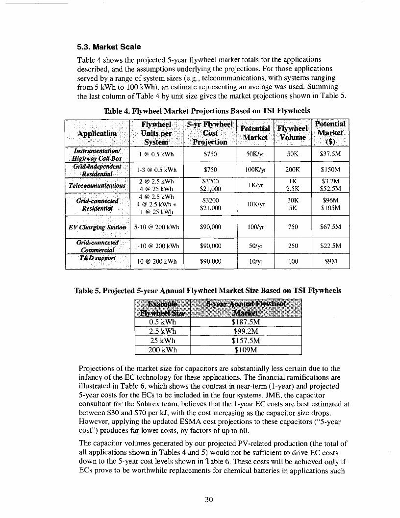
Table 4 shows the projected 5-year flywheel market totals for the applicationsdescribed, and the assumptions underlying the projections. For those applicationsserved by a range of system sizes (e.g., telecommunications, with systems rangingfrom 5 kWh to 100 kwh), an estimate representing an average was used. Summingthe last column of Table 4 by unit size gives the market projections shown in Table 5.
Table 4. Flywheel Market Projections Based on TSI Flywheels
Flywheel 5-yr Flywheel PotentialApplication Units per cost
Potential Flywheel Market
system ProjectionMarket Volume
($)hmtrutnentotionl
Highway CUUBox1 @ 0.5 kWh $750 5oKlyr 50K $37.5M
(kid-independentResidenfiul
1-3 @ 0.5 kWh $750 loowyr 200K $150M
Tekkommunicatit?ns2 @ 2.5 kWh $3200 1K/y
lK $3.2M4@25kWh $21,000 2.5K $52.5M
GM-coaneetid4 @ 2.5 kWh
[email protected]+$3200 Iowyr 30K $96M
Res&ndid l@25kWh $21,000 5K $105M
W Ckwgi”ng Station 5-10 @ 200kWh $90,000 looly 750 $67.5M
Grid-connectedCommercial
1-10 @ 200kWh $90,000 5olyc 250 $22.5M
T&Ll SUp#Wt10 @ 200kWh $90,000 lolyr 100 $9M
Table 5. Projected 5-year Annual Flywheel Market Size Based on TSI Flywheels
25 kWh $157.5M200 kWh $ 109M
Projections of the market size for capacitors are substantially less certain due to theinfancy of the EC technology for these applications. The financial ramifications areillustrated in Table 6, which shows the contrast in near-term ( 1-year) and projected5-year costs for the ECS to be included in the four systems. JME, the capacitorconsultant for the Solarex team, believes that the 1-year EC costs are best estimated atbetween $30 and $70 per kJ, with the cost increasing as the capacitor size drops.However, applying the updated ESMA cost projections to these capacitors (“5-yearcost”) produces far lower costs, by factors of up to 60.
The capacitor volumes generated by our projected PV-related production (the total ofall applications shown in Tables 4 and 5) would not be sufficient to drive EC costsdown to the 5-year cost levels shown in Table 6. These costs will be achieved only ifECS prove to be worthwhile replacements for chemical batteries in applications such
30
as those now demonstrated in Russia. If that occurs, EC production volume willskyrocket and costs may fall to the projected level.
In this case, adding EC capability to the example energy storage systems described inthis report will be a very small segment of their impact on the whole field of energystorage technology; just how small is indicated by our projected EC market total. Ifall applications in Tables 4 and 5 were realized, the annual flywheel market wouldtotal $553 million. However, the cost of the associated ECS, using 5-year costs, wouldbe only $1.3 million.
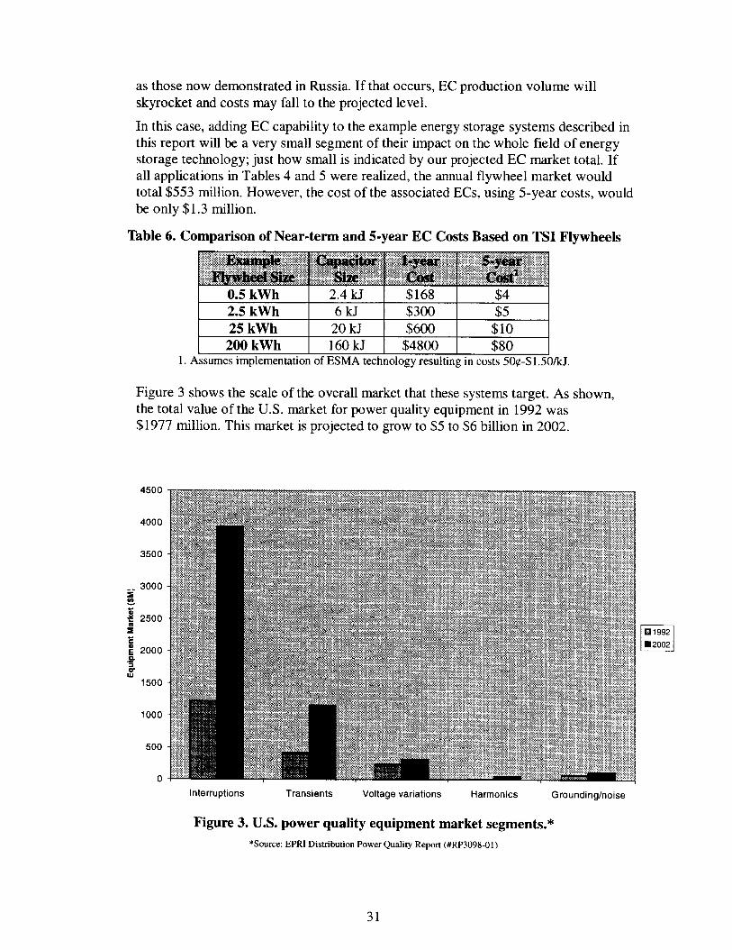
Table 6. Comparison of Near-term and 5-year EC Costs Based on TSI Flywheels
Figure 3 shows the scale of the overall market that these systems target. As shown,the total value of the U.S. market for power qualit y equipment in 1992 was$1977 million. This market is projected to grow to $5 to $6 billion in 2002.
4500
4000
3500
1000
500
0Interruptions Transients Voltage variations Harmonics Grounding/noise
❑El 1992
❑ 2002
Figure 3. U.S. power quality equipment market segments.*
*Source: EPRI Distribution Power Quality Report (#RP3098-O 1)
31

Consequently, the flywheel/EC systems described constitute 10- 15% of the powerquality equipment market as it exists today. The true market would be substantiallylarger, as it includes remote power (approximately $1 billion in the PV market alone)and other segments not considered in the data represented by Figure 3.
32
6. Conclusions
6.1. Flywheel Status
The representative TSI flywheel used in this study is presently in the prototype teststage as a direct replacement for a storage battery in a communications application,and should also be tested as the primary storage medium in a demonstration PVsystem. TSI and Solarex are proceeding independently with a preliminaryinvestigation of the interaction of PV modules and the TSI flywheel.
6.2. Development of Low-cost ECS
The Russian firm ESMA has substantial experience in designing and operating ECS ina number of applications, including demonstration projects with the U.S. Army, theNational Aeronautics and Space Administration (NASA), and EPRI. Of particularinterest is the use of ECS as the sole energy storage medium for various vehicles,which required the development of ECS with characteristics very different fromtraditional capacitor applications, but very close to those which could replace lead-acid batteries in PV applications and other applications. ESMA’s projected prices aredrastically lower than current capacitor prices. This issue should be addressed withrespect to broad use in energy systems, including PV systems.
6.3. Flywheel/Capacitor Synergy
The primary hypothesis this study—that a synergistic relationship exists betweenflywheels and ECS in energy storage/delivery systems—has been confwmedconceptually. Further investigation is needed to quantify the performance andeconomic tradeoffs of this synergy and its effect on overall system costs.
Specifically, effort should be directed at determining whether adding a large EC to aflywheel would, by insulating the flywheel from demand surges:
. enable major changes in flywheel design (lighter shaft, smallerconductor, etc.);
● enable reduction in nominal flywheel capacity for a given application;
. lengthen system life; and/or
● significantly decrease the overall storage system’s cost.
33

Intentionally left blank.
34
7. Appendix A: Capacitor Manufacturers and Technologies
A@OwerThe technology is a double-layer capacitor based on carbon electrodes with anorganic electrolyte. Their capacitor has an RC time constant of 2.5 s. The form factoris prismatic. Operating voltage is set at 3.0 V maximum. Alupower has pilot lineequipment in place.
AsahiThe technology is a double-layer capacitor based on carbon electrodes with anorganic electrolyte. The form factor is a cylinder. They have product lines of low-vokage ECS in sizes up to 50 F, sold mainly for memory backup and relatedapplications. Asahi Glass has presented several papers describing developmentactivities of large, high-power capacitors.
cap-xxThe technology is a double-layer capacitor based on carbon electrodes with an
organic electrolyte. Cap-XX has an operating pilot production line and anticipatesthat costs will decrease as production volume increases.
ECOND Internationa~ Inc+The technology is a double-layer capacitor based on carbon electrodes and anaqueous electrolyte. Their form factor is a right cylinder. ECOND has beenmanufacturing large, high-voltage capacitors for more than 10 years, and has manythousands of units in use in various military and automotive applications in Russia,and more recently in the U.S. They recently supplied 1.6 MJ of 200-V capacitors toNASA for a hybrid bus project. These units were rated at 50 kJ each. ECONDpresently manufactures their product in Moscow.
ELIT Stock Co.ELIT has two technologies: a symmetric carbon system and a carbon/metal-oxidepseudocapacitor with an aqueous electrolyte. Their system has an RC time constant of0.25 s, and a prismatic form factor. They have been manufacturing large, high-voltagecapacitors for more than 7 years, and have many thousands of units in the field invarious Russian military and automotive applications. ELIT presently manufacturestheir product in Kursk, Russia.
ESMA Joint Stock co.The technology is a combination of double-layer capacitors based on carbonelectrodes with an aqueous electrolyte, and metal-oxide pseudocapacitors using anaqueous electrolyte. Starting capacitors have an RC time constant of approximately1.0s and a prismatic form factor. Their traction capacitors have an RC time constantof approximately 12 minutes. They have been manufacturing large, high-voltagecapacitors for more than 5 years, and have many units in the field, including severalvehicles powered by their traction capacitors.
35

Evans Capacitor Co.The technology uses an electrolytic capacitor anode (aluminum oxide on aluminum)combined with an electrochemical cathode. This approach circumvents potentialvoltage imbalance problems associated with multicell components. The componenthas an RC-time constant of less than 0.5 s, and a right cylinder form factor. Evans ispresently fabricating laboratory prototypes.
Federal FabricsThe technology is a double-layer capacitor based on carbon electrodes with anorganic electrolyte. They have presented papers describing the performance of theirsmall devices.
GEThe technology is a double-layer capacitor based on carbon electrodes with a non-aqueous electrolyte. The form factor is unspecified. Operating voltage is set at 2.5 Vmaximum. GE has been under contract to Ford Motor Co.
Maxwell TechnologiesThe technology is a double-layer capacitor based on carbon electrodes with anorganic electrolyte. The capacitor has an RC time constant of 1.4 s, and the formfactor is nearly prismatic. Maxwell has a pilot production line in place. They haveassembled large banks of capacitors for UPS applications, and understand how tomaintain voltage balance in high-voltage systems.
NEC CorporationThe technology is a double-layer capacitor based on carbon electrodes and anaqueous electrolyte. Their main product lines are low-voltage (5.5 V) ECS formemory backup and related applications. NEC has presented papers on developmentof large capacitors over the past 5 years.
Panasonic Industrial Co.The technology is a double-layer capacitor based on carbon electrodes with anorganic electrolyte. The capacitor has an RC time constant of 1.5 s, and a right-cylinder form factor. Panasonic has a pilot production line in place and has beensampling this product (470-F to 1500-F capacitor rated at 2.3 V) for more than3 years.
Polystor Corp.The technology is a double-layer capacitor based on carbon electrodes with anorganic electrolyte. Papers have been presented on small (AA-size) single-celldevices.
RElloz IImThe technology is a double-layer capacitor based on carbon electrodes with anorganic electrolyte. The capacitor has an RC time constant of 7.0 s. The form factor isprismatic. Redox presently assembles laboratory prototypes, and has constructedseveral 45-cell modules.
36
Sfu?rThe technology is a double-layer capacitor based on carbon electrodes with anorganic electrolyte. The y have reported on cylindrical devices for use in applicationsranging from wireless communication to UPS systems.
SRIThe energy storage component is based on lithium-ion battery technology. It has beendescribed as a very-high-rate battery having a sloping discharge, like a capacitor. Theelectrolfie was said to be nonflammable. The RC time constant and the form factor ofthe technology was not provided. Cycle efficiency is unknown, as is state-of-chargepower performance behavior. SRI is developing a pilot line for their product. It is notclear that they have investigated voltage balance in the high-voltage configuration.
37

Intentionally lefi blank,
38

8. Appendix B: Vendor Information
Alupower, Inc.Alex Karpinski82 Mechanic StreetPawcatuck, CT 06379860-599-1100, ext. 320
Asahi Glass Co. Ltd.Takeshi MorimotoResearch CenterJapan
Cap-XX Pty. Ltd.Dr. George PaulChristina Road (cm Birmingham Ave.)Villawood, NSW 2163Australia612-9914-3703
ECOND International, Inc.Frank Lev9337-B Katy FreewayHouston, TX 77024905-479-3202
ELIT Stock Co.Alexey BehakovAccumulator plant305013, Kursk, Russia7-07122-461-51
Evans Capacitor Co.David A. Evans33 Eastern Ave.East Providence, RI 02914401-434-5600
Federal FabricsZ. Horiwitz15 Middlesex St.North Chelmsford,MA018 10508-470-1859
Maxwell TechnologiesMark S. Cohn4949 Greencraig LaneSan Diego, CA 92123619-576-7704
NEC CorporationYoshihiko SaikiCircuit Component DivisionJapan
Panasonic Industrial Co.Dan Yamashita6550 Katella Ave., #17A-11Cypress, CA 90630714-373-7336
Polystor, Corp.James Kaschmitter6918 Sierra Ct.Dublin, CA 94568510-829-6251
REDOX, Inc.Nikola Marincic24 River StreetWinchester, MA 01890617-729-3179
SAFT America, Inc.Guy Chagnon107 Beaver Court,Cockeysville, MD 21030410-771-3200
SRI InternationalPhilip Cox33 Ravenwood Ave.Menlo Park, CA 94025415-859-2938
GEElihu C. JerabekCorporate Research and DevelopmentNiskayuna, NY 12309518-387-5065
39

Intentionally left blank.
40
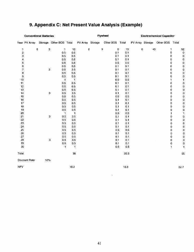
9. Appendix C: Net Present Value Analysis (Example)
Conventional Batteries Flywheel Electrochemical Capacitor
Year PV Array Storage Other BOS Total PV Array Storage Other BOS Total PV Array Storage Other BOS Total
1
2
3
4
5
6
7
8
9
10
1112
13
14
15
16
17
18
19
20
21
22
23
24
25
26
27
28
29
30
Total
6 3
3
3
3
3
Discount Rate 1o%
NPV
10.5
0.5
0.5
0.5
0.5
0.5
0.5
0.5
1
0.5
0.5
0.5
0.5
0.5
0.5
0.5
0.5
0.5
1
0.5
0.5
0.5
0.5
0.5
0.5
0.5
0.5
0.5
1
10
0.5
0.5
0.5
0.5
0.5
3.5
0.5
0.5
1
0.5
0.5
0.5
3.5
0.5
0.5
0.5
0.5
0.5
1
3.5
0.5
0.5
0.5
0.5
0.5
0.5
3.5
0.5
1
38
18.2
6 9 0
0.1
0.1
0.1
0.5
0.1
0.1
0.1
0.1
0.5
0.1
0.1
0.1
0.1
0.5
0.1
0.1
0.1
0.1
0.5
0.1
0.1
0.1
0.1
0.5
0.1
0.1
0.1
0.1
0.5
15
0.1
0.1
0.1
0.5
0.1
0.1
0.1
0.1
0.5
0.1
0.1
0.1
0.1
0.5
0.1
0.1
0.1
0.1
0.5
0,1
0.1
0.1
0.1
0.5
0.1
0.1
0.1
0.1
0.5
20.3
16.6
6 45 1
0
0
0
0
0
0
0
0
1
0
0
0
0
0
0
0
0
0
1
0
0
0
0
0
0
0
0
0
1
52
0
0
0
0
0
0
0
0
1
0
0
0
0
0
0
0
0
0
1
0
0
0
0
0
0
0
0
0
1
55
52.7
41


Distribution
Bob Weaver777 Wildwood LanePalo Alto, CA 94303
Hans WeinerichABB Power T&D Co., Inc.1460 Livingston Ave.P.O. BOX 6005North Brunswick, NJ 08902-6005
Robert WillsAdvanced Energy SystemsRiverview MillP.O. BOX 262Wilton, NH 03086
Percy FrisbeyAlaska State Div. of Energy333 West Fourth Ave.Suite 220Anchorage, AK 99501-2341
Michael L. GravelyAmerican Superconductor Corp.8371 Bunchberry CourtCitrus Heights, CA 95610
Per DanforsABB Power T&D Co., Inc.16250 West Glendale DriveNew Berlin, WI 53151
Jim BalthazarActive Power11525 Stonehollow Dr.Suite 255Austin, TX 78758
B. TiedemanAlaska State Div. of Energy333 West Fourth Ave.Suite 220Anchorage, AK 99501-2341
P. CrumpAlaska State Div. of Energy333 West Fourth Ave.Suite 220Anchorage, AK 99501-2341
C. ShihAmerican Elec. Pwr. Serv. Corp.1 Riverside PlazaColumbus, OH 43215
Christopher G. StrugAmerican Superconductor Corp.Two Technology DriveWestborough, MA 01581
Tim BallApplied Power CorporationSolar Engineering1210 Homann Drive SELacey, WA 98503
Christian St-PierreARGO-TECH Productions, Inc.Subsidiary of Hydro-Quebec1580 de CoulombBoucherville, QC J4B 7Z7CANADA
Bill DeLucaArgonne National Laboratories9700 South Cass AvenueCTD, Bldg. 205Argonne, IL 60439
Ray HobbsArizona Public Service400 North Fifth StreetP.0, BOX5399, MS8931Phoenix, AZ 85072-3999
Meera KohlerAnchorage Municipal Light & Pwr1200 East 1st AvenueAnchorage, AK 99501
Ralph M. NigroApplied Energy Group, Inc.46 Winding Hill DriveHockessin, DE 19707
Gary HenriksenArgonne National Laboratories9700 South Cass AvenueCTD, Bldg. 205Argonne, IL 60439
Herb HaydenArizona Public Semite400 North Fifth StreetP.O. BOX 53999,MS8931Phoenix, AZ 85072-3999
Robert HammondArizona State University East6001 S. Power Rd.Bldg. 539Mesa, AZ 85206

Edward C. KernAscension Technology, Inc.P.O. BOX6314Lincoln, MA 01773-6314
Glenn CampbellBabcock & WilcoxP.O. BOX785Lynchburg, VA 24505
Michael L. BergeyBergey Windpower2001 Priestley AvenueNorman, OK 73069
Massoud AssefpourBHP Research& Tech Dev.600 Bourke StreetMelbourne Victoria, 3000AUSTRALIA
Gerald W. 13raunBP Solarex630 Solarex CourtFrederick, MD 21703
Gary MarkleAVO International510 Township Line Rd.Blue Bell, PA 19422
Richard L. HockneyBeacon Power Corp.6 ~1]1 St.Woburn Industrial ParkWoburn, MA 01801-1721
Klaus KramerBerliner Kraft und Licht (BEWAG)Stauffenbergstrasse 261000 Berlin 30GERMANY
Samuel B. WrightBoeingInform., Space & Defense Sys.P.O. BOX 3999 MS 82-97Seattle, WA 98124-2499
Salim JabbourBusiness Management Consulting24704 Voorhees DriveLOS Altos Hills, CA 94022
Dr. Sudhan S. MisraC&D Charter Pwr. Systems, Inc.Washington & Cherry Sts.Conshohocken. PA 19428
Larry S. MeisnerC&D Powercom1400 Union Meeting RoadP.0, Box 3053Blue Bell, PA 19422-0858
J. HolmesCalifornia State Air Rest. BoardResearch DivisionP.O. BOX2815Sacramento, CA 95812
Rod BoucherCalpine Corporation50 W. San FernandoSuite 550San Jose, CA 95113
John CooleyChugach Elec. Association, Inc.P.O. BOX 196300Anchorage, AK 99519-6300
Dr. Les HoldenC&D Charter Pwr. Systems, IncWashington & Cherry Sts.Conshohocken, PA 19428
Jon EdwardsCalifornia Energy Commission1516 Ninth Street, MS-46Sacramento, CA 95814
Pramod P. KulkarniCalifornia Energy ComissionResearch & Dev. Office1516 9th Street, MS43Sacramento, CA 95814-5512
Tom LovasChugach Elec. Association, Inc.P.O. BOX 196300Anchorage, AK 99519-6300
M. LebowConsolidated Edison4 Irving PlaceNew York NY 10003
N. TaiConsolidated Edison4 Irving PlaceNew Yor~NY 10003
R. B. SloanCrescent EMCP.O. BOX 1831Statesville, NC 28687
Bob GalyenDelphi Energy. & EngineManagement SystemsP.O. BOX 502650Indianapolis, IN 46250
Paul MaupinDepartment of Energy19901 Germantown RdER-14 E-422Germantown, MD 20874-1290
Joseph J. IannucciDistributed Utility Associates1062 Concannon Blvd.Livermore, CA 94550
R. StackCorn Belt Electric CooperativeP.O. Box 816Bloomington, IL 61702
J. Michael HingaDelphi Energy & EngineManagement SystemsP.O. BOX502650Indianapolis, IN 46250
Bob RiderDelphi Energy & EngineManagement SystemsP.O. BOX 502650Indianapolis, IN 46250
Albert R. LandgrebeDepartment of Energy - RetiredB 14 Suffex LaneMillsboro, DE 19966
Alan CollinsonEA Technology LimitedChester CH1 6ESCapenhurst, EnglandI.JIWTD KINGDOM

Jim DeGrusonEagle-Picher Industries. Inc.C & Porter StreetJoplin, MO 64802
Daniel R. BruckECG Consulting Group, Inc.55-6 Woodlake RoadAlbany, NY 12203
Robert SchainkerElec. Pwr. Research InstituteP.O. BOX 10412Palo Alto, CA 94303-0813
Phillip C. SymonsElectrochemical EngineeringConsultants, Inc.1295 Kelly Park CircleMorgan Hill, CA 95037
Michael DodgeElectrosourceP. O. BOX7115Loveland, CO 80537
M. StantonEast Penn Manufact. Co., Inc.Deka RoadLyon Station, PA 19536
Steve EckroadElec. Pwr. Research InstituteP.O. BOX 10412Palo Alto, CA 94303-0813
Steve ChapelE}ec. Pwr. Research InstituteP.O. BOX 10412Palo Alto, CA 94303-0813
Dave FederElectrochemical EnergyStorage Systems, Inc.35 Ridgedale AvenueMadison, NJ 07940
Harald HaegermarkElforsk-Swedish Elec Utilities R&D CoElforsk ABStockholm, S-101 53Sweden

Eric RuddEltech Research Corporation625 East StreetFairport Harbor, OH 44077
Phil DiPietroEnergetic501 School Street SWSuite 500Washington, DC 20024
Mindi J. Farber-DeAndaEnergetic501 School Street SWSuite 500Washington, DC 20024
Rich ScheerEnergetic501 School Street SWSuite 500Washington, DC 20024
Greg J. BallEnergy & Env. Economics, Inc.353 Sacramento StreetSuite 1540San Francisco, CA 94111
Jennifer SchillingEnergetic501 School Street SWSuite 500Washington, DC 20024
Paula A. TaylorEnergetic7164 Gateway DriveColumbia, MD 21046
Howard LowittEnergetic7164 Gateway DriveColumbia, MD 21046
Laura JohnsonEnergetic, Inc.7164 Gateway DriveColumbia, MD 21046
Amber Gray-FennerEnergy Communications Consulting7204 Marigot Rd. NWAlbuquerque, NM 87120

Al Pivec
Energy Systems Consulting
41 Springbrook Road
Livingston, NJ 07039
Robert Duval
EnerVision
P,O, BOX 450789Atlanta, GA 31145-0789
Erik Hennig
EUS GmbH
MunscheidstraBe 14
Gelsenkirchen, 45886
Germany
J. Mills
Firing Circuits, Inc.
P.O. BOX 2007Norwalk, CT 06852-2007
Steven J. Durand
Florida Solar Energy Center
1679 Clearlake Road
Cocoa, FL 32922-5703
Dale Butler
EnerTec Pty. Ltd.
349 Coronation Drive
PO Box 1139, Milton BC Old 4044
Auchenflower, Queensland, 4066
AUSTRALIA
David H. DaCosta
Ergenics, Inc.
247 Margaret King Avenue
RingWood, NJ 07456
John Breckenridge
Exide Electronics
8609 Six Forks Road
Raleigh, NC 27615
James P. Dunlop
Florida Solar Energy Center
1679 Clearlake Road
Cocoa, FL 32922-5703
Steven Kraft
Frost & Sullivan
2525 Charleston Road
Mountain View, CA 94043

Dave Coleman
Frost & Sullivan
2525 Charleston Road
Mountain View, CA 94043
Nick Miller
General Electric Company
1 River Road
Building 2, Room 605
Schenectady, NY 12345
Gerry Woolf
Gerry Woolf Associates
17 Westmeston Avenue
Rottingdean, East Sussex, BN2 8AL
UNITED ICIINGDOM
George Hunt
GNB Tech. Ind. Battery Co.
Woodlake Corporate Park
829 ParkView Blvd.
Lombard, IL 60148-3249
Sanjay Deshpande’
GNB Technologies
Woodlake Corporate Park
829 ParkView Blvd.
Lombard, IL 60148-3249
Bob Zrebiec
GE Industrial & Pwr. Services
640 Freedom Business Center
King of Prussia, PA 1!)046
Declan Daly
General Electric Drive Systems1501 Roanoke Blvd.
Salem, VA 24153
Anthony B. LaConti
Giner, Inc.
14 Spring Street
Waltham, MA 02451-4497
Joe Szymborski
GNB Tech. Ind. Battery Co.
Woodlake Corporate Park
829 ParkView Blvd.
Lombard, IL 60148-3249
J. Boehm
GNB Tech. Ind. Battely Co.
Woodlake Corporate Park
829 ParkView Blvd.
Lombard, IL 60148-3249
Steven Haagensen
Golden Valley Elec. Assoc., Inc.
758 Illinois Street
P.O. BOX 71249Fairbanks, AK 99701
Clyde Nagata
Hawaii Electric Light Co.
P.O. BOX 1027Hilo, HI 96720
Carl Parker
LLZRO
2525 Meridian Parkway
P.O. BOX 12036
Research Triangle Park, NC 27709
Jerome F. Cole
ILZRO
2525 Meridian Parkway
PO BOX 12036Research Triangle Park, NC 27709
Ken Belfer
Innovative Power Sources
1419 Via Jon Jose Road
Alamo, CA 94507
Ben FJorris
Gridwise Engineering Company121 Starlight PlaceDanville, CA 94526
George H. NolinHL&P Energy ServicesP.O. Box 4300Houston, TX 77210-4300
Patrick MoseleyILZRO2525 Meridian ParkwayP.O. BOX 12036Research Triangle Park, NC 27709
R. MyersImperial Oil Resources, Ltd.3535 Research Rd. NWCalgary, Alberta, T2L 2K8CANADA
David Warar (2)Intercon Limited6865 Lincoln AvenueLincolnwood, IL 60646

A. Kamal KalafalaIntermagnetics General Corp.450 Old Niskayuna RoadP.O. BOX461Latham, NY 12110-0461
Gerard H. C. M. ThijssenKEMA T&D PowerUtrechtseweg310P.O. Box 9035ET, Ernhem, 6800The Netherlands
Frank McLarnon
Lawrence Berkeley National Lab
University of California
One Cyclotron Road
Berkeley, CA 94720
J. Ray SmithLawrence Livermore Nat’1 LabUniversity of CaliforniaP.O. BOX808, L-641Livermore, CA 94551
Joseph MorabitoLucent Technologies, Inc.600 Mountain View Ave.P.O. BOX636Murray Hill, NJ 07974-0636
John NealIntemationl Business& Tech.Services, Inc.9220 Tayloes Neck RoadNanjemoy, MD 20662
Elton CairnsLawrence Berkeley Nat”l LabUniversity of CaliforniaOne Cyclotron RoadBerkeley, CA 94720
IGm KinoshltaLawrence Berkeley Nat’1 LabUniversity of CaliforniaOne Cyclotron RoadBerkeley, CA 94720
Susan Marie SchoenungLongitude 122 West, Inc.1010 Doyle StreetSuite 10Menlo Park, CA 94025
Cecilia Y. MakLucent Technologies3000 Skyline DriveRoom 855Mesquite, TX 75149-1802

Stephen R. ConnorsMassachusetts Inst of TechThe Energy LaboratoryRm E40-465Cambridge, MA 02139-4307
D. NowackMicron Corporation158 Orchard LaneWinchester, TN 37398
Byron StaffordNat’] Renewable Energy Lab1617 Cole BoulevardGolden, CO 80401-3393
Richard DeBlasioNat’1 Renewable Energy Lab1617 Cole BoulevardGolden, CO 80401-3393
Larry FlowersNat’1 Renewable Energy Lab1617 Cole BoulevardGolden, CO 80401-3393
Dutch AchenbachMetlakatla Power& LightP.O. Box 3593.5 Mile Airport RoadMetlakatla, AK 99926
Dr. Christine E. PlattNat’] Institute of Standards& Tech,Room A225 Administration Bldg.Gaithersburg, MD 20899
Holly ThomasNat’1 Renewable Energy Lab1617 Cole BoulevardGolden, CO 80401-3393
Jim GreenNat’1 Renewable Energy Lab1617 Cole BoulevardGolden, CO 80401-3393
Susan HockNat’1Renewable Energy Lab1617 Cole BoulevardGolden, CO 80401-3393

Anthony PriceNational Power PLCHarwell Int’1Business Ctr.Harwell, Didcot, OX11 OQALondon
Bill BrooksNC Solar CenterCorner of German & WesternBox 7401 NCSURaleigh, NC 27695-740
Bart ChezarNew York Power Authority1633 BroadwayNew York NY 10019
Denise ZurnNorthern States Power Co414 Nicollet MallMinneapolis, MN 55401
John StovalOak Ridge National LaboratoryP.O. BOX2008Bldg. 3147, MS-6070Oak Ridge, TN 37831-6070
Steven P. LindenbergNational Rural Elec Cooperative Assoc.4301 Wilson Blvd.SSER9-207Arlington, VA 22203-1860
Andrew L. RosenthalNew Mexico State UniversitySouthwest Tech. Dev. InstituteBox 30001 /Dept. 3SOLLas Cruces, NM 88003-8001
Gary G. KarnNorthern States Power Co.1518 Chestnut Avenue NorthMinneapolis, MN 55403
Jack BrownNPA TechnologyTwo University PlaceSuite 700Durham, NC 27707
Robert HawseyOak Ridge National LaboratoryP.O. BOX2008Bldg. 3025, MS-6040Oak Ridge, TN 37831-6040

James VanCoeveringOak Ridge National LaboratoryP.O. Box 2008Bldg. 3147, MS-6070Oak Ridge, TN 37831-6070
Hans MeyerOmnion Pwr. Engineering Corp.2010 Energy DriveP.O. BOX 879East Troy, WI 53120
John DeStreesePacific Northwest Nat’1 LabBattelle Blvd.P.O. BOX999, K5-02Richland, WA 99352
Thomas H. SchucanPaul Scherrer InstitutCH -5232 Villigen PSISwitzerland
Stan SostromPOWER Engineers, IncP.O. Box 7773870 USHwy 16Newcastle, WY 82701
Brendan KirbyOak Ridge National LaboratoryP.O. BOX 2008Bldg. 3147, MS-6070Oak Ridge, TN 37831-6070
Douglas R. DanleyOrion Energy Corporation10087 Tyler Place ##5Ijamsville, MD 21754
Daryl BrownPacific Northwest Nat’1 LabBattelle Blvd. MS K8-07P.O. Box 999Richland, WA 99352
Brad JohnsonPEPCO1900 Pennsylvania NWWashington, DC 20068
P. PrabhakaraPower Technologies, Inc.1482 Erie Blvd.P.O. BOX 1058Schenectady, NY 12301
Henry W. ZainingerPower Technologies, Inc775 Sunrise AvenueSuite 210Roseville, CA 95661
Reznor I. OrrPowercell Corporation101 Main StreetSuite 9Cambridge, MA 02142-1519
Roger FlynnPublic Service Co. of New MexicoAlvarado Square MS-2838Albuquerque, NM 87158
Norman LindsayQueensland Department ofMines and EnergyG.P.O. BOX 194Brisbane, 4001QLD. AUSTRALIA
Al RandallRaytheon Eng. & Constructors700 South Ash StreetP.O. BOX5888Denver, CO 80217
Rick WinterPowercell Corporation101 Main StreetSuite 9Cambridge, MA 0214;!-1519
Jerry NealPublic Service Co. of New MexicoAlvarado Square MS-BA52Albuquerque, NM 87158
Wenceslao TorresPuerto Rico Elec. Pwr. AuthorityG.P.O. BOX4267San Juan, PR 00936-426
J. ThompsonR&D Associates2100 Washington Blvd.Arlington, VA 22204-5706
K. FerrisRMS Company87 Martling AvenuePleasantville, NY 105’70

Ole VigerstolSAFT America, Inc.711 Industrial Blvd.Valdosta, GA 13601
Michael C. SaftSAFT Research& Dev. Ctr.107 Beaver CourtCockeysville, MD 21030
H. LundstromSalt River ProjectP.O. BOX 52025MS PAB 357Phoenix, AZ 85072-2025
Robert ReevesSentech, Inc.9 Eaton RoadTroy, NY 12180
Rajat K. SenSentech, Inc.4733 Bethesda AvenueSuite 608Bethesda, MD 20814
Guy ChagnonSAFT Research& Dev. Ctr.107 Beaver CourtCockeysville, MD 21030
G. E. “Ernie” PalominoSalt River ProjectP.O. BOX 52025MS PAB 357Phoenix, AZ 85072-2025
Dr. Charles FeinsteinSanta Clara UniversityDept. of Dec. & Info. SciencesLeavey School of Bus. & AdminSanta Clara, CA 95053
Kurt Klunder
Sentech, Inc.4733 Bethesda Avenue
Suite 608
Bethesda, MD 20814
Nicole MillerSentech, Inc.4733 Bethesda AvenueSuite 608Bethesda, MD 20814

Clay AldrichSiemens Solar4650 Adohr LaneP.O. BOX6032Camarillo. CA 93011
Scott SklarSolar Energy Ind. Assoc. (SEIA)122 C Street NW4th FloorWashington, DC 20001-2104
Bruce R. Rauhe, Jr.Southern Company Services, Inc.600 North 18th StreetP.O. BOX2625Birmingham, AL 35202-2625
Richard N. SchweinbergSouthern California Edison6070 N. Irwindale AvenueSuite 1Irwindale, CA 91702
George ZinkStored Energy Engineering7601 E. 88th PlaceIndianapolis, IN 46256
Deepak DivanSofl Switching Technologies2224 Evergreen RoadSuite 6Middleton, WI 53562
Naum PinskySouthern California Edison2244 Walnut Grove Ave.P.O. Box 800, Room 418Rosemead, CA 91770
K. VakhshoorzadehSouthern Company Services, Inc.600 North 18th StreetP.O. BOX2625Birmingham, AL 3520;!-2625
C. SeitzSRI International333 Ravenswood AvenueMenlo Park, CA 94025
Bob BishStored Energy Engineering7601 E. 88th PlaceIndianapolis, IN 46256

Jon HurwitchSwitch Technologies4733 Bethesda AvenueSuite 608Bethesda, MD 20814
Thomas J. JenkinThe Brattle Group44 Brattle StreetCambridge, MA 02138-3736
Charles E. BaklsThe Pennsylvania State University227 Hammond BuildingUniversity Park, PA 16802
Tom AnyosThe Technology Group, Inc.63 Linden Avenue
Atherton, CA 94027-2161
Bill ErdmanTrace Technologies6952 Preston AvenueLivermore, CA 94550
Terri HensleyTampa Electric CompanyP.O. Box 111Tampa, FL 33601-0111
Haukur AsgeirssonThe Detroit Edison Company2000 2nd Ave.435 SBDetroit, MI 48226-1279
Michael OriansThe Solar ConnectionP.O. BOX 1138Morro Bay, CA 93443
Bill RoppeneckerTrace Engineering Division5916 195th NortheastArlington, WA 98223
Michael BehnkeTrace Technologies6952 Preston Ave.P.O. Box 5049Livermore, CA 94550

Donald A. BenderTrinity Flywheel Power6724D Preston AvenueLivermore, CA 94550
James FangueTU ElectricR&D ProgramsP.O. Box 970Fort Worth, TX 76101
Jim DaleyU.S. Department of Energy1000 Independence Ave. SWEE-12 FORSTLWashington, DC 20585
James E. RannelsU.S. Department of Energy1000 Independence Ave. SWEE-11 FORSTLWashington, DC 20585-0121
Mark B. GinsbergU.S. Department of Energy1000 Independence Ave. SWEE-90 FORSTL 5E-052Washington, DC 20585
Jim DrizosTrojan Battery Company12380 Clark StreetSanta Fe Springs, CA 90670
Paul C. KlimasU.S. Agency for Intn’1 DevelopmentCenter for EnvironmentWashington, DC 20523-3800
Dan T. TonU.S. Department of Energy1000 Independence Ave. SWEE-11 FORSTLWashington, DC 20585
Gary A. BucklnghamU.S. Department of EnergyAlbuquerque Operations OffIceP.O. Box 5400Albuquerque, NM 87185
Alex O. BuiawkaU.S. Department of Energy1000 Independence Ave. SWEE-11 FORSTLWashington, DC 20585

J. A. MazerU.S. Department of Energy1000 Independence Ave. SWEE-11 FORSTLWashington, DC 20585
Richard J. KingU.S. Department of Energy1000 Independence Ave. SWEE-11 FORSTL, 5H-095Washington, DC 20585
Kenneth L. HeitnerU.S. Department of Energy1000 Independence Ave. SWEE-32 FORSTLWashington, DC 20585
Neal RossmeisslU.S. Department of Energy1000 Independence Ave. SWEE-13 FORSTLWashington, DC 20585
R. EynonU.S. Department of Energy1000 Independence Ave. SWEI-821 FORSTLWashington, DC 20585
J. P. ArchibaldU.S. Department of Energy1000 Independence Ave. SWEE-90 FORSTLWashington, DC 20585
Russ EatonU.S. Department of EnergyGolden Field OffIce1617 Cole Blvd., Bldg. 17Golden, CO 80401
Bob BrewerU.S. Department of Energy1000 Independence Ave. SWEE-10 FORSTLWashington, DC 20585
Allan JelacicU.S. Department of Energy1000 Independence Ave. SWEE-12 FORSTLWashington, DC 20585
Alex G. CrawleyU.S. Department of Energy1000 Independence Ave. SWEE-90 FORSTLWashington, DC 20585
Philip N. OverholtU.S. Department of Energy1000 Independence Ave. SWEE-11 FORSTLWashington, DC 20585-0121
Pandit G. PatilU.S. Department of Energy1000 Independence Ave. SWEE-32 FORSTLWashington, DC 20585
Jack CadoganU.S. Department of Energy1000 Independence Ave. SWEE- 11 FORSTLWashington, DC 20585
Dr. Gerald P. CeasarU.S. Department of CommerceNIST/ATPBldg 101, Room 623Gaithersburg, MD 20899
Steve BitterlyU.S. Flywheel Systems1125-A Business Center CircleNewbury Park, CA 91320
W. ButlerU.S. Department of Energy1000 Independence Ave. SWPA-3 FORSTLWashington, DC 2058:5
Allan HoffmanU.S. Department of Energy1000 Independence Ave. SWEE-10 FORSTLWashington, DC 20585
Joe GaldoU.S. Department of Energy1000 Independence Ave. SWEE-1 OFORSTLWashington, DC 2058:5
Dr. h-ire GyukU.S. Department of Energy1000 Independence Ave. SWEE-14 FORSTLWashington, DC 2058.5
Wayne TaylorU.S. NavyCode 83BOOOD,NAWSChina Lake, CA 93555
Edward BeardsworthUFTO951 Lincoln AvenuePalo Alto, CA 94301-3041
John HerbstUniversity of Texas at AustinJ.J. Pickel Research CampusMail Code R7000Austin, TX 78712
G. Alan PalinUrenco (Capenhurst) Ltd.Capenhurst, Chester, CH1 6ERUNITED KINGDOM
Mike SternUtility Power Group941 O-G DeSoto AvenueChatsworth, CA 91311-4947
Gary VernoVirginia PowerInnsbrook Technical Center5000 Dominion Blvd.Glen Ellen, VA 23233
Tien Q. DuongUnited States Department of Energy1000 Independence Ave. SWEE-32 FORSTL, Rm. 5G-030Washington, DC 20585
Max AndersonUniversity of Missouri - Rolls112 Electrical Eng. Bldg.Rolls, MO 65401-0249
Steve HesterUtility Photo Voltaic Group1800 M Street NWWashington, DC 20036-5802
Rick UbaldiVEDCO Energy12 Agatha LaneWayne, NJ 07470
Alex Q. HuangVirginia Polytechnic Instit. & State UniVirginia Power Electronics Center672 Whittemore HallBlacksburg, VA 24061

Randy BevinWalt Disney WorldDesign and Eng’gP.o. Box 10,000Lake Buena Vista, FL 32830-1000
Howard SaundersWestinghouse STC1310 Beulah RoadPittsburgh, PA 15235
Frank TarantinoYuasa, Inc.2366 Bernville RoadPO. Box 14145Reading, PA 19612-4145
Gene CookYuasa, Inc.2366 Bernville RoadP.O. Box 14145Reading, PA 19612-4145
Robert J. ParryZBB Technologies11607 West Dearbourn Ave.Wauwatosa, WI 53226-3961
Gerald J. KeaneWestinghouse Elec. Corp.Energy Management Division4400 Alafaya TrailOrlando, FL 32826-2399
Tom MattyWestinghouseP.O. BOX 17230Maryland, MD 21023
Nicholas J. MagnaniYuasa, Inc.2366 Bernville RoadP.O. Box 14145Reading, PA 19612-4145
R. KristiansenYuasa-Exide, Inc.35 Loch Lomond LaneMiddleton, NY 10941-1421
Phillip A. EldlerZBB Technologies, Inc.11607 West Dearbourn Ave.Wauwatosa, WI 53226-3961

MS-0619, Review & Approval For DOE/OSTI (001 11) (1)MS-0212, Andrew Phillips (10230)MS-0340, Jeff W.Braithwaite(1832)MS-0457, Gary N. Beeler (2000)MS-0537, Stan Atcitty (2314)MS-0953, William E. Alzheimer (2500)MS-0953, J. Thomas Cutchen (2500)MS-0613, Daniel H. Doughty (2521)MS-061 3, Terry Unkelhaeuser (2521)MS-061 3, RudyG.Jungst(2521)MS-0614, Dennis E. Mitchell (2522)MS-0614, Robert W. Bickes (2523)MS-0613, Garth P. Corey (2525)MS-061 3, Gus P. Rodriguez (2525)MS-0613, Terry Crow (2525)MS-0613, Imelda Francis (2525)MS-0613, Na.ncy H. Clark (2525)MS-0613, Paul C. Butler (2525) (10~MS-0613, John D. Boyes (2525)MS-0899, Technical Library (491 6)MS-0741, Sam Varnado (6200)MS-0704, Abbas A. Akhil (6201)MS-0708, Henry M. Dodd (6214)
2)
MS-0753, Christopher Cameron (621 8)MS-0753, Russell H. Bonn (6218)MS-0753, Tom Hund (6218)MS-0753, John W. Stevens (6218)MS-0753, Ward I. Bower (6218)MS-0455, Marjorie L. Tatro (623 1)MS-9403, Jim Wang (8713)MS-901 8, Central Technical Files (8940-2)MS-1 193, Dean C. Rovang (9531)