Embed Size (px)
Citation preview
International Research Journal of Engineering and Technology (IRJET) e-ISSN: 2395-0056
Volume: 08 Issue: 10 | Oct 2021 www.irjet.net p-ISSN: 2395-0072
© 2021, IRJET | Impact Factor value: 7.529 | ISO 9001:2008 Certified Journal | Page 1896
Nanditha S1, Deepaligowda K2, Pavana R Kowshik3
1Department of Electronics and Communication, University Visvesvaraya College of Engineering, Karnataka, India 2Department of Electrical and Electronics, JSS Science and Technology University, Karnataka, India 3Department of Electrical and Electronics, JSS Science and Technology University, Karnataka, India
----------------------------------------------------------------------***--------------------------------------------------------------------
Abstract – Indian armed forces are the second largest standing army in the world, our soldiers’ lives are a risk not only during wars but off the battlefields as well, where their health conditions become worse due to extreme weather conditions, they work in causing variations in health parameters like heartbeat, blood pressure and oxygen level etc... which under severe situation causes health problems and even death. In this project we intend to develop IoT based Health Monitoring and location tracking system for soldiers in order to protect them from severe health problems and to track their location and monitor their health conditions. The proposed system keeps track of real time health parameters like heartbeat, blood pressure, body temperature and oxygen level etc. record the data along with location of soldiers and sends the real time information to control room. This process is done using Internet of Things (IoT) which acts as platform to monitor the health parameter and location continuously to the control room. Knowing the exact location and health parameter and location continuously to the control room. Knowing the exact location and health status of a soldier it will be easy to provide the necessary medical support in short duration. This will save many lives.
1.INTRODUCTION The soldiers play an essential role in nation security, but in critical situations majority of soldiers are losing life due to lack of information regarding real time health status and not able to communicate with control room. The proposed IoT based health monitoring and location tracking system continuously records the health status of soldiers and their location and there by send the information to control room. If any abnormalities are identified in the health condition of the soldier, immediate action can be taken within a short duration. The proposed system has 2 units one of which is soldiers unit (wearable one) which includes heartbeat sensor, temperature sensor and oxygen level indicator etc. which monitors health conditions and tracks soldiers location using GPS technology thereby transmit data to other unit which is control room unit, the control room unit will receive the soldier’s data through IoT and checks for any abnormalities in the data received and thus helps soldiers to get proper medical aid within a short time.
1.1 Literature Survey Veena Tripathi and Faizan Shakeel have proposed the system, which is IoT driven health monitoring unit having combination of sensors, RFID, NFC, Bluetooth, ZigBee for measurement and monitoring vital functions like blood pressure, heart rate, cholesterol levels, blood glucose and temperature. Obtained data will be stored in Implantable wireless identifiable devices which can be accessed in emergency situations by using IoT [1]. Vaishnavi Patil, Vaibhav Kshirsagar and Sanjay Singh Thakur have proposed the system, which measures 5 parameters (such as ECG, heartbeat, respiration, temperature and blood pressure) and uses Arduino Mega controller along with non-invasive biomedical sensors to collect data and is uploaded to Thing Speak cloud [2]. Emre Oner Tartan and Cebrail Ciflikli have proposed the system, which monitors various physiological signal, one of these signals is heart rate which is measured on board or by wearable heart rate sensor. This methodology uses the facilities provided by the mobile technology and exhibit a geolocation-based heart rate monitoring system. The developed mobile application sends alarm message through notification and allows to communicate with health expert for consultancy [3]. Yang Gu1, Jianfei shen and Yiqiang Chen have proposed the smart watch-based system, which provides information about heart rate, ECG and blood pressure. A communication interface is built with another device through Bluetooth [4]. Brijesh Iyer and Niket Patil have proposed the system, which can be placed on the body of soldiers to track their current location and health status. This collected information will be send through IoT into the control room. This model consists of tiny wearable sensors and transmission modules [5]. Iftekhar Uddin Ahmed, Humayun Rashid and Nazia Hassan have proposed the system for children with autism, which updates the health conditions and location of children. The system is able to send the notification and alerts to the parents and caretakers, when there is variations in health condition and child is detected to be an out of predefined coordinate [6].
IoT based Health Monitoring and Location Tracking System for Soldiers
International Research Journal of Engineering and Technology (IRJET) e-ISSN: 2395-0056
Volume: 08 Issue: 10 | Oct 2021 www.irjet.net p-ISSN: 2395-0072
© 2021, IRJET | Impact Factor value: 7.529 | ISO 9001:2008 Certified Journal | Page 1897
Vivek Pardeshi, Saurabh Sagar, Swapnil Murmurwar and Pankaj Hage has proposed the system, which monitors the health condition of patients. This information is transmitting to the server through GSM technologies. Also, in case of emergency, automatically generating alerts will be sent to the family members and doctor, if any unusual activity is detected by or near the patient [7].
1.2 Problem Formulation From the various works studied in literature survey it is understood that the soldiers’ lives will be at risk all the time due to severe atmospheric conditions they work in, that brings enormous variations in their health parameters like blood pressure, heart beat, temperature, oxygen level etc which has to be monitored by the health care unit to establish communication with soldier and also reach the exact location in time with probable solution to safeguard the life of soldiers.
1.3 Objectives of the Project To overcome the above said problem and come up with a solution we are intending to develop a low cost IoT based health monitoring and location tracking system for soldiers. The developed model must be able
1. To monitor the health condition of soldiers by taking real time information.
2. To track the accurate location of soldiers through GPS receiver and send it to the control room
1.4 Methodology To meet the objectives, a low cost IoT based health monitoring and location tracking system is to be developed which continuously monitor the real time health parameter and location of soldiers by polling sensor and GPS location at fixed interval of time, the monitoring node is Arduino uno. The sensor utilized here are heartbeat sensor and temperature sensor, IoT module is Wi-Fi, GPS receiver for tracking the position of soldiers. Wi-Fi module is used to send the monitored real time data of soldiers to the cloud. The sensors, Wi-Fi and GPS receiver are interfaced to the Arduino Uno microprocessor using jumper wires and is programmed using C language. To know the current location and health parameters, the user can login on ThingSpeak web browser by entering username and password of the user in control room. After entering password, the web application page opens with the output in graphical representation manner.
1.5 Justification for implementing this project Extreme atmospheric conditions faced by soldiers leads to severe health problems or even death, whereas monitoring of their health conditions along with location could and
taking necessary actions on time will save their lives. Here the role of our health monitoring and location tracking unit which solves this problem effectively through its special features listed below
Measuring health parameters Location tracking and sharing Effective communication Good battery life Customize Cost effective Easy to use
2. INTRODUCTION TO HEALTH MONITORING SYSTEM This Section briefs about health monitoring system, it measures parameters like blood pressure, heartbeat and oxygen level etc. The body parameters are measured by using sensors which involves in continuously monitoring the body parameter of soldiers.
2.1 Health Monitoring System Health monitoring system is a sophisticated technology that acts as an alternate method to traditional way of managing patients and their health. It features the functionalities of remote health care system. Basically, remote health care system has distributed network of sensor for the purpose of continuous and consecutive monitoring of patient’s health parameter. It requires potential security of the remotely collected data. This system needs to be fast, secured and have reliable storage due to the growing size of the patient’s information and to process it at later point of time.
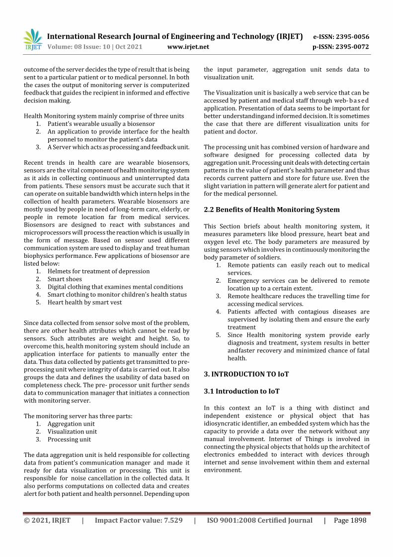
Fig 2.1 Architecture of Health Monitoring System Fig 2.1 shows a basic architecture for health monitoring system. The input to the health monitoring system consists of health attributes such as blood pressure, pulse rate, blood sugar level, weight. These attributes have to be self –input by the patient to the system. The value of patient’s health attributes is sensed using biosensors which are of wearable type. The data being sensed by biosensors are sent to health monitoring server. The health monitoring server is equipped with proper hardware and software for complex analytics of the sensed data and server will provide results based on analysis. The
International Research Journal of Engineering and Technology (IRJET) e-ISSN: 2395-0056
Volume: 08 Issue: 10 | Oct 2021 www.irjet.net p-ISSN: 2395-0072
© 2021, IRJET | Impact Factor value: 7.529 | ISO 9001:2008 Certified Journal | Page 1898
outcome of the server decides the type of result that is being sent to a particular patient or to medical personnel. In both the cases the output of monitoring server is computerized feedback that guides the recipient in informed and effective decision making. Health Monitoring system mainly comprise of three units
1. Patient’s wearable usually a biosensor 2. An application to provide interface for the health
personnel to monitor the patient’s data 3. A Server which acts as processing and feedback unit.
Recent trends in health care are wearable biosensors, sensors are the vital component of health monitoring system as it aids in collecting continuous and uninterrupted data from patients. These sensors must be accurate such that it can operate on suitable bandwidth which intern helps in the collection of health parameters. Wearable biosensors are mostly used by people in need of long-term care, elderly, or people in remote location far from medical services. Biosensors are designed to react with substances and microprocessors will process the reaction which is usually in the form of message. Based on sensor used different communication system are used to display and treat human biophysics performance. Few applications of biosensor are listed below:
1. Helmets for treatment of depression 2. Smart shoes 3. Digital clothing that examines mental conditions 4. Smart clothing to monitor children’s health status 5. Heart health by smart vest
Since data collected from sensor solve most of the problem, there are other health attributes which cannot be read by sensors. Such attributes are weight and height. So, to overcome this, health monitoring system should include an application interface for patients to manually enter the data. Thus data collected by patients get transmitted to pre-processing unit where integrity of data is carried out. It also groups the data and defines the usability of data based on completeness check. The pre- processor unit further sends data to communication manager that initiates a connection with monitoring server. The monitoring server has three parts:
1. Aggregation unit 2. Visualization unit 3. Processing unit
The data aggregation unit is held responsible for collecting data from patient’s communication manager and made it ready for data visualization or processing. This unit is responsible for noise cancellation in the collected data. It also performs computations on collected data and creates alert for both patient and health personnel. Depending upon
the input parameter, aggregation unit sends data to visualization unit. The Visualization unit is basically a web service that can be accessed by patient and medical staff through web- b a s ed application. Presentation of data seems to be important for better understanding and informed decision. It is sometimes the case that there are different visualization units for patient and doctor. The processing unit has combined version of hardware and software designed for processing collected data by aggregation unit. Processing unit deals with detecting certain patterns in the value of patient’s health parameter and thus records current pattern and store for future use. Even the slight variation in pattern will generate alert for patient and for the medical personnel.
2.2 Benefits of Health Monitoring System This Section briefs about health monitoring system, it measures parameters like blood pressure, heart beat and oxygen level etc. The body parameters are measured by using sensors which involves in continuously monitoring the body parameter of soldiers.
1. Remote patients can easily reach out to medical services.
2. Emergency services can be delivered to remote location up to a certain extent.
3. Remote healthcare reduces the travelling time for accessing medical services.
4. Patients affected with contagious diseases are supervised by isolating them and ensure the early treatment
5. Since Health monitoring system provide early diagnosis and treatment, system results in better and faster recovery and minimized chance of fatal health.
3. INTRODUCTION TO IoT 3.1 Introduction to IoT In this context an IoT is a thing with distinct and independent existence or physical object that has idiosyncratic identifier, an embedded system which has the capacity to provide a data over the network without any manual involvement. Internet of Things is involved in connecting the physical objects that holds up the architect of electronics embedded to interact with devices through internet and sense involvement within them and external environment.
International Research Journal of Engineering and Technology (IRJET) e-ISSN: 2395-0056
Volume: 08 Issue: 10 | Oct 2021 www.irjet.net p-ISSN: 2395-0072
© 2021, IRJET | Impact Factor value: 7.529 | ISO 9001:2008 Certified Journal | Page 1899
3.2 IoT in Healthcare
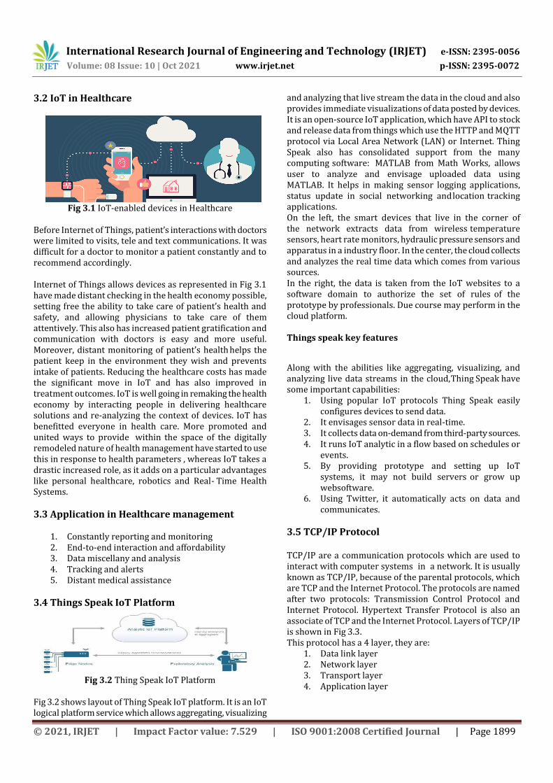
Fig 3.1 IoT-enabled devices in Healthcare
Before Internet of Things, patient’s interactions with doctors were limited to visits, tele and text communications. It was difficult for a doctor to monitor a patient constantly and to recommend accordingly. Internet of Things allows devices as represented in Fig 3.1 have made distant checking in the health economy possible, setting free the ability to take care of patient’s health and safety, and allowing physicians to take care of them attentively. This also has increased patient gratification and communication with doctors is easy and more useful. Moreover, distant monitoring of patient’s health helps the patient keep in the environment they wish and prevents intake of patients. Reducing the healthcare costs has made the significant move in IoT and has also improved in treatment outcomes. IoT is well going in remaking the health economy by interacting people in delivering healthcare solutions and re-analyzing the context of devices. IoT has benefitted everyone in health care. More promoted and united ways to provide within the space of the digitally remodeled nature of health management have started to use this in response to health parameters , whereas IoT takes a drastic increased role, as it adds on a particular advantages like personal healthcare, robotics and Real- Time Health Systems.
3.3 Application in Healthcare management
1. Constantly reporting and monitoring 2. End-to-end interaction and affordability 3. Data miscellany and analysis 4. Tracking and alerts 5. Distant medical assistance
3.4 Things Speak IoT Platform
Fig 3.2 Thing Speak IoT Platform
Fig 3.2 shows layout of Thing Speak IoT platform. It is an IoT logical platform service which allows aggregating, visualizing
and analyzing that live stream the data in the cloud and also provides immediate visualizations of data posted by devices. It is an open-source IoT application, which have API to stock and release data from things which use the HTTP and MQTT protocol via Local Area Network (LAN) or Internet. Thing Speak also has consolidated support from the many computing software: MATLAB from Math Works, allows user to analyze and envisage uploaded data using MATLAB. It helps in making sensor logging applications, status update in social networking and location tracking applications. On the left, the smart devices that live in the corner of the network extracts data from wireless temperature sensors, heart rate monitors, hydraulic pressure sensors and apparatus in a industry floor. In the center, the cloud collects and analyzes the real time data which comes from various sources. In the right, the data is taken from the IoT websites to a software domain to authorize the set of rules of the prototype by professionals. Due course may perform in the cloud platform. Things speak key features
Along with the abilities like aggregating, visualizing, and analyzing live data streams in the cloud, Thing Speak have some important capabilities:
1. Using popular IoT protocols Thing Speak easily configures devices to send data.
2. It envisages sensor data in real-time. 3. It collects data on-demand from third-party sources. 4. It runs IoT analytic in a flow based on schedules or
events. 5. By providing prototype and setting up IoT
systems, it may not build servers or grow up web software.
6. Using Twitter, it automatically acts on data and communicates.
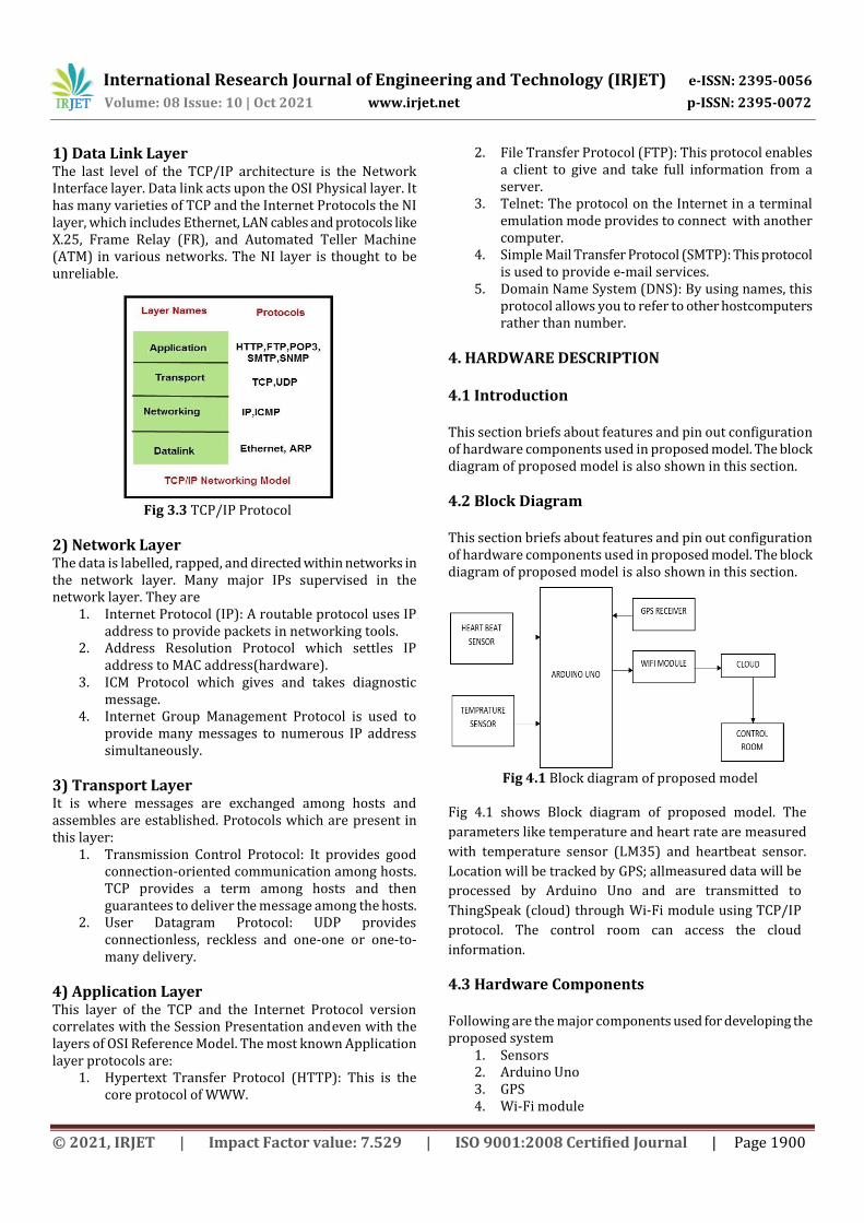
3.5 TCP/IP Protocol TCP/IP are a communication protocols which are used to interact with computer systems in a network. It is usually known as TCP/IP, because of the parental protocols, which are TCP and the Internet Protocol. The protocols are named after two protocols: Transmission Control Protocol and Internet Protocol. Hypertext Transfer Protocol is also an associate of TCP and the Internet Protocol. Layers of TCP/IP is shown in Fig 3.3. This protocol has a 4 layer, they are:
1. Data link layer 2. Network layer 3. Transport layer 4. Application layer
International Research Journal of Engineering and Technology (IRJET) e-ISSN: 2395-0056
Volume: 08 Issue: 10 | Oct 2021 www.irjet.net p-ISSN: 2395-0072
© 2021, IRJET | Impact Factor value: 7.529 | ISO 9001:2008 Certified Journal | Page 1900
1) Data Link Layer The last level of the TCP/IP architecture is the Network Interface layer. Data link acts upon the OSI Physical layer. It has many varieties of TCP and the Internet Protocols the NI layer, which includes Ethernet, LAN cables and protocols like X.25, Frame Relay (FR), and Automated Teller Machine (ATM) in various networks. The NI layer is thought to be unreliable.
Fig 3.3 TCP/IP Protocol
2) Network Layer The data is labelled, rapped, and directed within networks in the network layer. Many major IPs supervised in the network layer. They are
1. Internet Protocol (IP): A routable protocol uses IP address to provide packets in networking tools.
2. Address Resolution Protocol which settles IP address to MAC address(hardware).
3. ICM Protocol which gives and takes diagnostic message.
4. Internet Group Management Protocol is used to provide many messages to numerous IP address simultaneously.
3) Transport Layer It is where messages are exchanged among hosts and assembles are established. Protocols which are present in this layer:
1. Transmission Control Protocol: It provides good connection-oriented communication among hosts. TCP provides a term among hosts and then guarantees to deliver the message among the hosts.
2. User Datagram Protocol: UDP provides connectionless, reckless and one-one or one-to-many delivery.
4) Application Layer This layer of the TCP and the Internet Protocol version correlates with the Session Presentation and even with the layers of OSI Reference Model. The most known Application layer protocols are:
1. Hypertext Transfer Protocol (HTTP): This is the core protocol of WWW.
2. File Transfer Protocol (FTP): This protocol enables a client to give and take full information from a server.
3. Telnet: The protocol on the Internet in a terminal emulation mode provides to connect with another computer.
4. Simple Mail Transfer Protocol (SMTP): This protocol is used to provide e-mail services.
5. Domain Name System (DNS): By using names, this protocol allows you to refer to other host computers rather than number.
4. HARDWARE DESCRIPTION 4.1 Introduction This section briefs about features and pin out configuration of hardware components used in proposed model. The block diagram of proposed model is also shown in this section.
4.2 Block Diagram This section briefs about features and pin out configuration of hardware components used in proposed model. The block diagram of proposed model is also shown in this section.
Fig 4.1 Block diagram of proposed model
4.3 Hardware Components Following are the major components used for developing the proposed system
1. Sensors 2. Arduino Uno 3. GPS 4. Wi-Fi module
Fig 4.1 shows Block diagram of proposed model. The
parameters like temperature and heart rate are measured
with temperature sensor (LM35) and heartbeat sensor.
Location will be tracked by GPS; all measured data will be
processed by Arduino Uno and are transmitted to
ThingSpeak (cloud) through Wi-Fi module using TCP/IP
protocol. The control room can access the cloud
information.
International Research Journal of Engineering and Technology (IRJET) e-ISSN: 2395-0056
Volume: 08 Issue: 10 | Oct 2021 www.irjet.net p-ISSN: 2395-0072
© 2021, IRJET | Impact Factor value: 7.529 | ISO 9001:2008 Certified Journal | Page 1901
4.3.1 Sensors Sensor is a device which produces a signal relating to quality being measured. Sensor converts the physical parameter being measured into signal which can be measured by electrically. A sensor is often used with other electronics, but can be also a mechanical sensor. There are large sensors available for various applications. In this project we use Bio-medical sensors. 4.3.1.1 Heartbeat Sensor Sensor is a device which produces a signal relating to quality being measured. Sensor converts the physical parameter being measured into signal which can be measured by electrically. A sensor is often used with other electronics but can be also a mechanical sensor. There are large sensors available for various applications. In this project we use Bio-medical sensors.
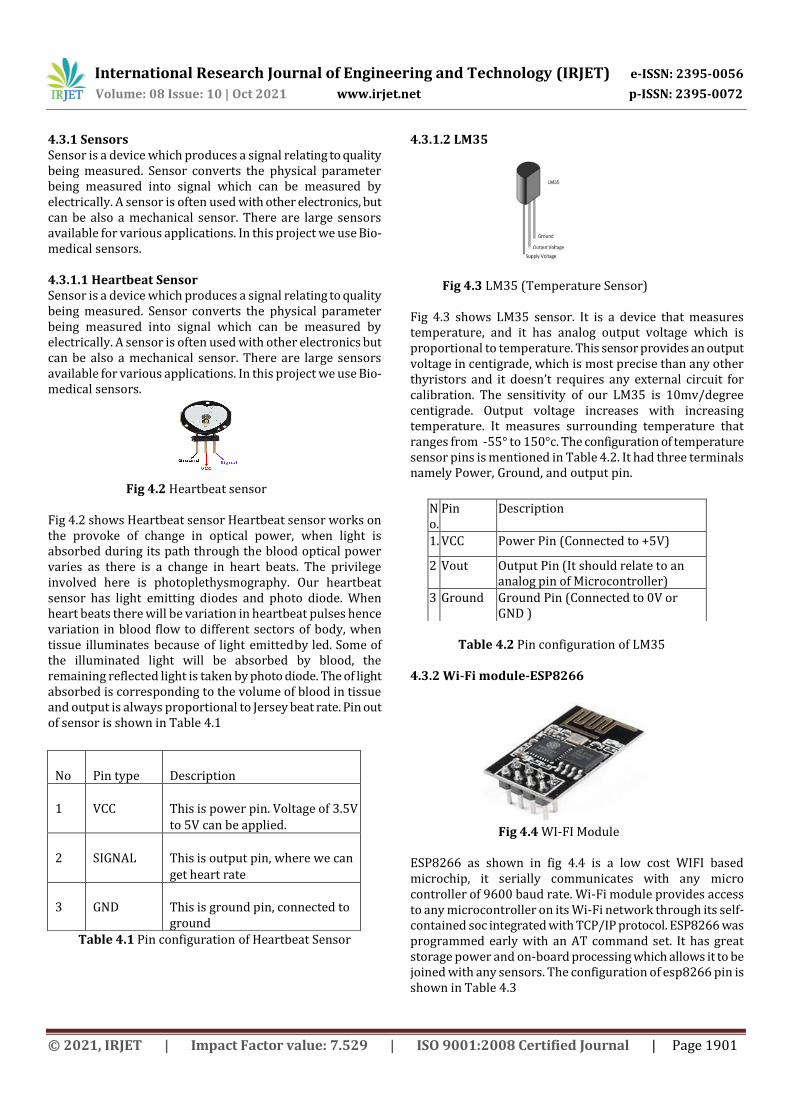
Fig 4.2 Heartbeat sensor
Fig 4.2 shows Heartbeat sensor Heartbeat sensor works on the provoke of change in optical power, when light is absorbed during its path through the blood optical power varies as there is a change in heart beats. The privilege involved here is photoplethysmography. Our heartbeat sensor has light emitting diodes and photo diode. When heart beats there will be variation in heartbeat pulses hence variation in blood flow to different sectors of body, when tissue illuminates because of light emitted by led. Some of the illuminated light will be absorbed by blood, the remaining reflected light is taken by photo diode. The of light absorbed is corresponding to the volume of blood in tissue and output is always proportional to Jersey beat rate. Pin out of sensor is shown in Table 4.1
Table 4.1 Pin configuration of Heartbeat Sensor
4.3.1.2 LM35
Fig 4.3 LM35 (Temperature Sensor) Fig 4.3 shows LM35 sensor. It is a device that measures temperature, and it has analog output voltage which is proportional to temperature. This sensor provides an output voltage in centigrade, which is most precise than any other thyristors and it doesn’t requires any external circuit for calibration. The sensitivity of our LM35 is 10mv/degree centigrade. Output voltage increases with increasing temperature. It measures surrounding temperature that ranges from -55° to 150°c. The configuration of temperature sensor pins is mentioned in Table 4.2. It had three terminals namely Power, Ground, and output pin.
Table 4.2 Pin configuration of LM35
4.3.2 Wi-Fi module-ESP8266
Fig 4.4 WI-FI Module
ESP8266 as shown in fig 4.4 is a low cost WIFI based microchip, it serially communicates with any micro controller of 9600 baud rate. Wi-Fi module provides access to any microcontroller on its Wi-Fi network through its self-contained soc integrated with TCP/IP protocol. ESP8266 was programmed early with an AT command set. It has great storage power and on-board processing which allows it to be joined with any sensors. The configuration of esp8266 pin is shown in Table 4.3
No
Pin type
Description
1
VCC
This is power pin. Voltage of 3.5V to 5V can be applied.
2
SIGNAL
This is output pin, where we can get heart rate
3
GND
This is ground pin, connected to ground
No.
Pin Description
1. VCC Power Pin (Connected to +5V)
2 Vout Output Pin (It should relate to an analog pin of Microcontroller)
3 Ground Ground Pin (Connected to 0V or GND )
International Research Journal of Engineering and Technology (IRJET) e-ISSN: 2395-0056
Volume: 08 Issue: 10 | Oct 2021 www.irjet.net p-ISSN: 2395-0072
© 2021, IRJET | Impact Factor value: 7.529 | ISO 9001:2008 Certified Journal | Page 1902
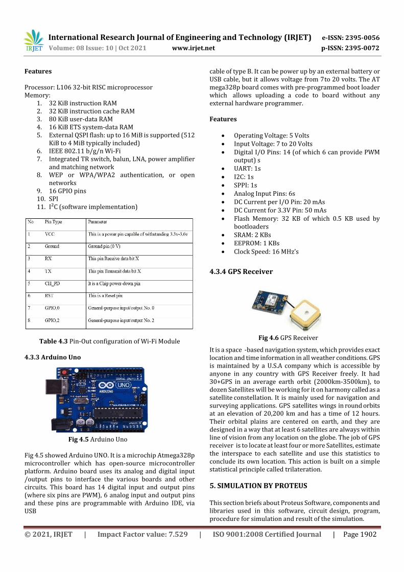
Features Processor: L106 32-bit RISC microprocessor Memory:
1. 32 KiB instruction RAM 2. 32 KiB instruction cache RAM 3. 80 KiB user-data RAM 4. 16 KiB ETS system-data RAM 5. External QSPI flash: up to 16 MiB is supported (512
KiB to 4 MiB typically included) 6. IEEE 802.11 b/g/n Wi-Fi 7. Integrated TR switch, balun, LNA, power amplifier
and matching network 8. WEP or WPA/WPA2 authentication, or open
networks 9. 16 GPIO pins 10. SPI 11. I²C (software implementation)
Table 4.3 Pin-Out configuration of Wi-Fi Module
4.3.3 Arduino Uno
Fig 4.5 Arduino Uno Fig 4.5 showed Arduino UNO. It is a microchip Atmega328p microcontroller which has open-source microcontroller platform. Arduino board uses its analog and digital input /output pins to interface the various boards and other circuits. This board has 14 digital input and output pins (where six pins are PWM), 6 analog input and output pins and these pins are programmable with Arduino IDE, via USB
cable of type B. It can be power up by an external battery or USB cable, but it allows voltage from 7 to 20 volts. The AT mega328p board comes with pre-programmed boot loader which allows uploading a code to board without any external hardware programmer. Features
Operating Voltage: 5 Volts Input Voltage: 7 to 20 Volts Digital I/O Pins: 14 (of which 6 can provide PWM
output) s UART: 1s I2C: 1s SPPI: 1s Analog Input Pins: 6s DC Current per I/O Pin: 20 mAs DC Current for 3.3V Pin: 50 mAs Flash Memory: 32 KB of which 0.5 KB used by
bootloaders SRAM: 2 KBs EEPROM: 1 KBs Clock Speed: 16 MHz’s
4.3.4 GPS Receiver
Fig 4.6 GPS Receiver
It is a space -based navigation system, which provides exact location and time information in all weather conditions. GPS is maintained by a U.S.A company which is accessible by anyone in any country with GPS Receiver freely. It had 30+GPS in an average earth orbit (2000km-3500km), to dozen Satellites will be working for it on harmony called as a satellite constellation. It is mainly used for navigation and surveying applications. GPS satellites wings in round orbits at an elevation of 20,200 km and has a time of 12 hours. Their orbital plains are centered on earth, and they are designed in a way that at least 6 satellites are always within line of vision from any location on the globe. The job of GPS receiver is to locate at least four or more Satellites, estimate the interspace to each satellite and use this statistics to conclude its own location. This action is built on a simple statistical principle called trilateration.
5. SIMULATION BY PROTEUS This section briefs about Proteus Software, components and libraries used in this software, circuit design, program, procedure for simulation and result of the simulation.
International Research Journal of Engineering and Technology (IRJET) e-ISSN: 2395-0056
Volume: 08 Issue: 10 | Oct 2021 www.irjet.net p-ISSN: 2395-0072
© 2021, IRJET | Impact Factor value: 7.529 | ISO 9001:2008 Certified Journal | Page 1903
5.1 Introduction to Proteus The Proteus is a design and simulating software developed by Labcenter for schematic capture, electronic circuit simulation and PCB (Printed Circuit Board) design. It is a best simulation for different designs with microcontroller. It is most used software because of availability of maximum number of microcontrollers. We can simulate our proposed model in Proteus simulation software. After simulating our circuit in proteus software we can make PCB design. It is a Virtual System Modeling (VSM) & circuit simulation application. This software includes simulation, animated components, block diagram for electric components, microcontroller-based design etc. it is also able to simulate interaction between microcontroller and digital or analog electronics connected to microcontroller. it is very useful software to understand the device behavior before implementing in real.
5.2 Components & Libraries The components Arduino, heartbeat sensor, temperature sensor and GPS module are used in our project. The used components model should be there in libraries of the software otherwise the software will be unable to simulate the circuit. Therefore, it is important to download the missing libraries from respective source. Table 5.1 shows the components and its libraries that are required for the simulation of our project. Using Arduino library, we can easily simulate Arduino boards in Proteus. Heartbeat sensor and GPS module is not available in Proteus software it must be downloaded from external sources.
Component Library Description
Arduino Uno R3 V1.0
Arduino TEP Arduino Uno
Heart beat Sensor
HeartBeatSensorTEP
Heart beat sensor
LM35 NATDAC Precision centigrade Temperature Sensor
POT-HG Active Highly Granularity Interactive Potentiometer
Button Active SPST Push button
GPS Module GpsTEP GPS Module v1.0
Table 5.1: Components & Libraries for Simulation
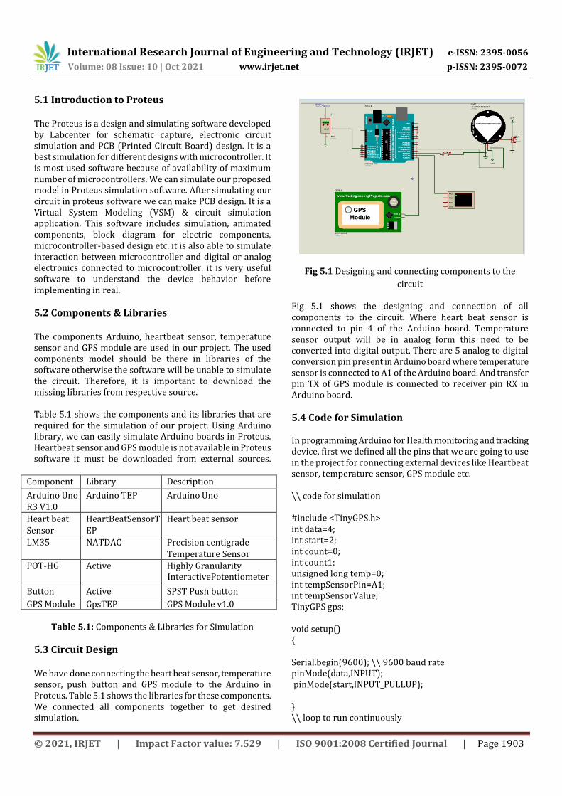
5.3 Circuit Design We have done connecting the heart beat sensor, temperature sensor, push button and GPS module to the Arduino in Proteus. Table 5.1 shows the libraries for these components. We connected all components together to get desired simulation.
Fig 5.1 Designing and connecting components to the
circuit
Fig 5.1 shows the designing and connection of all components to the circuit. Where heart beat sensor is connected to pin 4 of the Arduino board. Temperature sensor output will be in analog form this need to be converted into digital output. There are 5 analog to digital conversion pin present in Arduino board where temperature sensor is connected to A1 of the Arduino board. And transfer pin TX of GPS module is connected to receiver pin RX in Arduino board.
5.4 Code for Simulation In programming Arduino for Health monitoring and tracking device, first we defined all the pins that we are going to use in the project for connecting external devices like Heartbeat sensor, temperature sensor, GPS module etc. \\ code for simulation #include <TinyGPS.h> int data=4; int start=2; int count=0; int count1; unsigned long temp=0; int tempSensorPin=A1; int tempSensorValue; TinyGPS gps; void setup() { Serial.begin(9600); \\ 9600 baud rate pinMode(data,INPUT); pinMode(start,INPUT_PULLUP); } \\ loop to run continuously
International Research Journal of Engineering and Technology (IRJET) e-ISSN: 2395-0056
Volume: 08 Issue: 10 | Oct 2021 www.irjet.net p-ISSN: 2395-0072
© 2021, IRJET | Impact Factor value: 7.529 | ISO 9001:2008 Certified Journal | Page 1904
void loop() { Serial.print("PLACE YOUR FINGER"); Serial.println(); heart_beat(); temp_sen(); gps_loc(); } void heart_beat() { while(digitalRead(start)>0); temp=millis(); while(millis()<(temp+10000)) { if(analogRead(data)<100) { count=count+1; } } count=count*6; count1=count/1000; Serial.print("Heart Beat: "); Serial.print(count1); Serial.print("BPM"); Serial.println(); } void temp_sen() { Serial.print("Temperature:"); tempSensorValue=analogRead(tempSensorPin); tempSensorValue=(tempSensorValue*500)/1024; Serial.println(tempSensorValue); } void gps_loc() \\ to print latitude and longitude { bool new = false; unsigned long chars,start; unsigned short sentences, failed; \\ for one sec gps data for (start = millis(); millis() - start < 1000;) { while (Serial.available()) { char a = Serial.read(); if (gps.encode(a)) new = true; } } if (new) { float flat, flon;
unsigned long b; gps.f_get_position(&flat, &flon, &b); Serial.print("Lat = "); Serial.print(flat == TinyGPS:: INVALID ? 0.0 : flat, 6); Serial.print(" Long = "); Serial.print(flon == TinyGPS:: INVALID ? 0.0 : flon, 6); Serial.println(); } Serial.println(failed); }
5.5 Procedure for Simulation Step 1: Open Proteus software create new project and save the file in new folder. Step 2: A new design sheet will be opened. To select components for circuit design first click on component mode then click on pick from libraries then search or type the components name which are required for circuit design. Step 3: Select the component or type the component name in text box. If the components is not present in existing libraries, download the respective components library from external source. Table 5.1 shows the components and libraries that are used in our project. Step 4: Select Arduino, GPS, heartbeat sensor and LM35 for circuit design. Select the components and place it in the design sheet. Step 5: Place all the components in design sheet and make connection according to our requirement. Fig 5.1 shows the connection of components in design sheet.
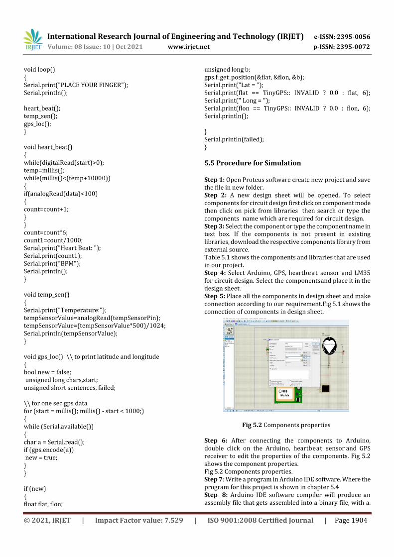
Fig 5.2 Components properties Step 6: After connecting the components to Arduino, double click on the Arduino, heartbeat sensor and GPS receiver to edit the properties of the components. Fig 5.2 shows the component properties. Fig 5.2 Components properties. Step 7: Write a program in Arduino IDE software. Where the program for this project is shown in chapter 5.4 Step 8: Arduino IDE software compiler will produce an assembly file that gets assembled into a binary file, with a.
International Research Journal of Engineering and Technology (IRJET) e-ISSN: 2395-0056
Volume: 08 Issue: 10 | Oct 2021 www.irjet.net p-ISSN: 2395-0072
© 2021, IRJET | Impact Factor value: 7.529 | ISO 9001:2008 Certified Journal | Page 1905
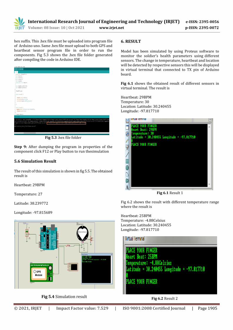
hex suffix. This .hex file must be uploaded into program file of Arduino uno. Same .hex file must upload to both GPS and heartbeat sensor program file in order to run the components. Fig 5.3 shows the .hex file folder generated after compiling the code in Arduino IDE.
Fig 5.3 .hex file folder
Step 9: After dumping the program in properties of the component click F12 or Play button to run the simulation
5.6 Simulation Result The result of this simulation is shown in fig 5.5. The obtained result is Heartbeat: 29BPM Temperature: 27 Latitude: 38.239772 Longitude: -97.815689
Fig 5.4 Simulation result
6. RESULT Model has been simulated by using Proteus software to monitor the soldier’s health parameters using different sensors. The change in temperature, heartbeat and location will be detected by respective sensors this will be displayed in virtual terminal that connected to TX pin of Arduino board. Fig 6.1 shows the obtained result of different sensors in virtual terminal. The result is Heartbeat: 29BPM Temperature: 30 Location: Latitude: 30.240455 Longitude: -97.817710
Fig 6.1 Result 1
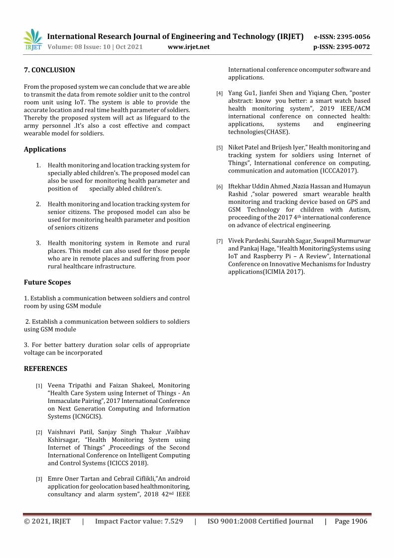
Fig 6.2 shows the result with different temperature range where the result is Heartbeat: 25BPM Temperature: -4.88Celsius Location: Latitude: 30.240455 Longitude: -97.817710
Fig 6.2 Result 2
International Research Journal of Engineering and Technology (IRJET) e-ISSN: 2395-0056
Volume: 08 Issue: 10 | Oct 2021 www.irjet.net p-ISSN: 2395-0072
© 2021, IRJET | Impact Factor value: 7.529 | ISO 9001:2008 Certified Journal | Page 1906
7. CONCLUSION From the proposed system we can conclude that we are able to transmit the data from remote soldier unit to the control room unit using IoT. The system is able to provide the accurate location and real time health parameter of soldiers. Thereby the proposed system will act as lifeguard to the army personnel .It’s also a cost effective and compact wearable model for soldiers.
Applications
1. Health monitoring and location tracking system for specially abled children’s. The proposed model can also be used for monitoring health parameter and position of specially abled children’s.
2. Health monitoring and location tracking system for
senior citizens. The proposed model can also be used for monitoring health parameter and position of seniors citizens
3. Health monitoring system in Remote and rural
places. This model can also used for those people who are in remote places and suffering from poor rural healthcare infrastructure.
Future Scopes 1. Establish a communication between soldiers and control room by using GSM module 2. Establish a communication between soldiers to soldiers using GSM module 3. For better battery duration solar cells of appropriate voltage can be incorporated
REFERENCES
[1] Veena Tripathi and Faizan Shakeel, Monitoring “Health Care System using Internet of Things - An Immaculate Pairing”, 2017 International Conference on Next Generation Computing and Information Systems (ICNGCIS).
[2] Vaishnavi Patil, Sanjay Singh Thakur ,Vaibhav
Kshirsagar, “Health Monitoring System using Internet of Things” ,Proceedings of the Second International Conference on Intelligent Computing and Control Systems (ICICCS 2018).
[3] Emre Oner Tartan and Cebrail Ciflikli,”An android
application for geolocation based health monitoring, consultancy and alarm system”, 2018 42nd IEEE
International conference on computer software and applications.
[4] Yang Gu1, Jianfei Shen and Yiqiang Chen, “poster
abstract: know you better: a smart watch based health monitoring system”, 2019 IEEE/ACM international conference on connected health: applications, systems and engineering technologies(CHASE).
[5] Niket Patel and Brijesh Iyer,” Health monitoring and
tracking system for soldiers using Internet of Things”, International conference on computing, communication and automation (ICCCA2017).
[6] Iftekhar Uddin Ahmed ,Nazia Hassan and Humayun Rashid ,“solar powered smart wearable health monitoring and tracking device based on GPS and GSM Technology for children with Autism, proceeding of the 2017 4th international conference on advance of electrical engineering.
[7] Vivek Pardeshi, Saurabh Sagar, Swapnil Murmurwar
and Pankaj Hage, “Health Monitoring Systems using IoT and Raspberry Pi – A Review”, International Conference on Innovative Mechanisms for Industry applications(ICIMIA 2017).