Embed Size (px)
Citation preview

Int. J. Appl. Math. Comput. Sci., 2019, Vol. 29, No. 2, 245–259DOI: 10.2478/amcs-2019-0018
IOT SENSING NETWORKS FOR GAIT VELOCITY MEASUREMENT
JYUN-JHE CHOU a, CHI-SHENG SHIH a,∗, WEI-DEAN WANG b, KUO-CHIN HUANG c
aGraduate Institute of Networking and MultimediaNational Taiwan University, No. 1, Sec. 4, Roosevelt Rd., Taipei 10617, Taiwan
e-mail: [email protected]
bDepartment of Medical Education and BioethicsNational Taiwan University, No. 1, Sec. 4, Roosevelt Rd., Taipei 10617, Taiwan
cDepartment of Family MedicineNational Taiwan University Hospital, No. 1, Changde St., Zhongzheng Dist., Taipei 10048, Taiwan
Gait velocity has been considered the sixth vital sign. It can be used not only to estimate the survival rate of the elderly,but also to predict the tendency of falling. Unfortunately, gait velocity is usually measured on a specially designed walkpath, which has to be done at clinics or health institutes. Wearable tracking services using an accelerometer or an inertialmeasurement unit can measure the velocity for a certain time interval, but not all the time, due to the lack of a sustainableenergy source. To tackle the shortcomings of wearable sensors, this work develops a framework to measure gait velocityusing distributed tracking services deployed indoors. Two major challenges are tackled in this paper. The first is to minimizethe sensing errors caused by thermal noise and overlapping sensing regions. The second is to minimize the data volume tobe stored or transmitted. Given numerous errors caused by remote sensing, the framework takes into account the temporaland spatial relationship among tracking services to calibrate the services systematically. Consequently, gait velocity can bemeasured without wearable sensors and with higher accuracy. The developed method is built on top of WuKong, which isan intelligent IoT middleware, to enable location and temporal-aware data collection. In this work, we present an iterativemethod to reduce the data volume collected by thermal sensors. The evaluation results show that the file size is up to 25%of that of the JPEG format when the RMSE is limited to 0.5◦.
Keywords: Internet of things, middleware, compression, data fusion, data reduction.
1. Introduction
Walking exercises the nervous, cardiovascular,pulmonary, musculoskeletal and hematologic systemsbecause it requires more oxygen to contract the muscles.Hence, gait velocity, called walking speed (Middletonet al., 2015), has become a valid and important metric forsenior populations (Middleton et al., 2015; Studenski etal., 2011; 2003).
Studenski et al. (2011) published a study that trackedgait velocity of over 34,000 seniors for periods rangingfrom 6 years to 21 years in the US. The study found thatthe predicted survival rate based on the age, sex, and gaitvelocity was as that accurate as predicted based on the age,sex, chronic conditions, smoking history, blood pressure,
∗Corresponding author
body mass index, and hospitalization. Consequently, itmotivated the industrial and academic communities todevelop a methodology to track and assess the risk basedon gait velocity. The following years led to many papersthat point to the importance of gait velocity as a predictorof degradation and exacerbation events associated withvarious chronic diseases including heart failure, COPD,kidney failure, stroke, etc. (Studenski et al., 2003;Pulignano et al., 2016; Kon et al., 2015; Kutner et al.,2015). In the US, there are 13 million seniors who livealone at home (Administration on Aging, 2015). Gaitvelocity and stride length are particularly important inthis case since they provide an assessment of fall risk,the ability to perform daily activities such as bathing andeating, and hence the potential for being independent. Theassessment of gait velocity is recommended to instruct

246 J.-J. Chou et al.
Fig. 1. Gait velocity measurement at smart homes.
the subjects to walk back and forth in a 5, 8 or 10 meterwalkway. Similar results were found in a study comparinga 3 meter walk test to the GAITRite electronic walkwayin individuals with a chronic stroke (Peters et al., 2014).
The above approaches are employed either at clinicalinstitutes or designated locations. They are recommendedby physicians but are required to be conducted in a limitedtime and location. Consequently, it is not trivial, ifnot difficult, to observe the change in long term. Itis desirable for the elderly, their family members, andphysicians to monitor gait velocity for the elderly all thetime at any location. However, the assessment should takeinto account several factors, including accuracy, privacy,portability, robustness, and applicability.
Shih et al. (2017) proposed a sensing system to beinstalled at home or a nursing institute without revealingprivacy and not using wearable devices. Given theproposed method, one may deploy several thermal sensorsin his/her apartments, as shown in Fig. 1. In this example,numbers of thermal sensors are deployed to increase thecoverage of the sensing signals. In large spaces suchas a living room, there will be more than one sensor inone space; in small spaces such as a corridor, there canbe only one sensor. One fundamental question is howmany sensors should be deployed and how these sensorswork together seamlessly to provide accurate gait velocitymeasurements.
To plan the number of sensors to be installed, one hasto take into account if the sensing regions should overlapand if there is any interference. Our observations showthat the above two questions are not trivial to answer. Thefirst challenge is to overcome the errors caused by coneshape sensing signals. Figure 2 illustrates such errors.
When the person walks into the covered region
shown on the left of the figure, the sensor will sense theleg first and show the heat sources at the edge of thecover space. Then, when the person continues to walktoward the center of the covered region, the sensor cansense the heat of their head, which is higher than thelegs, but continuously shows the heat sources at the edgeof the covered region. Consequently, on the heat map,they remain at the same locations; however, the personphysically walks for 20 cm to 40 cm, depending on theheight of the subject. This effect will lead to errors in gaitvelocity measurements on the edge of the covered region.
Another error is wrong location estimation,illustrated in Fig 3. (The dark and light grey boxesrepresent the heat sources whose temperature is greaterthan ambient temperature. Moreover, the heat sourcesmarked in dark grey are hotter than the those markedin light grey.) When the person stands in overlappingregions of two adjacent sensors, both the sensors can
Fig. 2. Gait speed errors caused by cone-shape signals.
Fig. 3. Location errors caused by cone-shape signals.

IoT sensing networks for gait velocity measurement 247
detect him or her. When the sensor estimates the locationof the person based on the highest temperature andassumes that it is the location of the head, the twosensors will mark the person at two different locations.Consequently, the heat source will be recorded twice inthe system, which is not correct.
Collaborating with neighboring thermal sensors, thewalking speed and walking length of a person can bedetected more precisely, and the detected area will becomelarge to cover all rooms in a house. However, theincreased number of sensors will cause a large workloadto the network and storage. Using the deployment in Fig. 1as an example, there are fifteen thermal sensors in anapartment. If Panasonic Grid-Eye sensors are used, eachof them will employ 2 bytes per pixel to store the data.This will generate 1.7 GB data per day when each sensorsamples at 10 Hz and there are 64 pixels per frame. Thechallenge is to reduce the amount of data transmitted overthe network and stored in the systems.Contribution. The contribution of this work is toenable gait velocity measurements at home and privatespaces. The developed method uses temporal andlocation properties of the sensed data to eliminate theaforementioned errors. The location framework in theWuKong middleware simplifies the development andmaintenance overhead, which are the foundations of theproposed methods.
The remainder of this paper is organized as follows.Section 2 presents related works and a background fordeveloping the methods. Section 3 presents the systemarchitecture, challenges, and mechanisms developed.Section 4 presents the evaluation results of the proposedmechanism, and Section 5 summarizes our works.
2. Background and related works
2.1. Related works. Activity recognition andmonitoring are two fundamental metrics to understandthe health condition of patients in health care. An activelifestyle leads to a healthy body condition and slows downthe aging, both physically and mentally. Hence there havebeen a large number of works on developing methods andtechnology of activity recognition and monitoring.
Many related works use wearable sensors to collectdata and recognize the type of activities. Lee andChung (2009) use shirts for activity monitoring. Asmart shirt which measures electrocardiogram (ECG)and acceleration signals for continuous and real timehealth monitoring is designed and developed. The shirtmainly consists of sensors for continuously monitoringhealth data and conductive fabric electrodes to get bodysignals. The measured physiological ECG data andphysical activity data are transmitted in an ad-hoc networkin the IEEE 802.15.4 communication standard to a basestation and a server PC for remote monitoring. The
wearable sensor devices are designed to fit well into shirtwith a small size and low power consumption to reducethe battery size. An adaptive filtering method to cancelartifact noise from conductive fabric electrodes in a shirtis also designed and tested to get clear ECG signals evenduring the running or physical exercise of a person.
Milenkovic et al. (2006) use wearable devices tocollect vital sign signals. Although wearable, it isnot likely to wear these devices 24/7 and collect data.In addition, the devices require clock synchronizationprotocols among wearable devices, which imposesunnecessary requirements for hardware devices and leadsto heavy power consumption. Alemdar and Ersoy (2010)study several systems designed for health care. Many ofthem rely on wearable devices to detect the location ofthe subject of interest or to collect vital sign information.The transceivers deployed in the environment forward thereceived data to a central database for further analysis.Using wearable devices to collect vital signs has its ownmerits. However, this approach only works when thesubjects of interest are wearing these devices and cannotbe used as the only way to collect health-care data.Our work proposes to deploy low-cost sensors in theenvironment to collect data, which can operate 24/7 andare not subject to users’ preference.
Gravina et al. (2017) propose an activity-as-a-serviceframework to support activity recognition and monitoringin mobility. The aim of this work is to provide a service tocollect data gathered by a body sensor network (BSN) andhigh performance computing for processing the collectedsensor data. It uses mobile devices as the transmissiongateway between wearable devices and cloud services.Fortino et al. (2015) propose a framework to collect datafrom multiple body sensor networks and process the datain a distributed manner.
Other works deploy sensors in the environment tocollect information and recognize the type of activities.Lu and Fu (2009) design and implement a robustlocation-aware activity recognition system to recognizeusers’ behaviors. The average accuracy of activitiescorrectly detected is 92%. Although the method providesrobust data collection, it requires a specially designedfloor which can measure pressure but is extremelyexpensive.
Yi et al. (2013) present a work to preserve theprivacy at wireless sensor networks. The aim of thatwork is to design a lightweight encryption algorithm toprotect the communication between the sensor node andserver. In our works, we will preserve the privacy whilesensing. Gheid and Challal (2016) propose a protocol toanalyze the sensed data without revealing privacy. Theprotocol consists of a cosine similarity protocol to assessthe similarity between the sensed activities and externalpatterns. Bourke et al. (2016) propose to use videoanalysis and a tri-axial accelerometer to recognize the

248 J.-J. Chou et al.
activity pattern. The aim is to use minimal sensors andprovide accurate detection results. However, privacy isnot preserved in this work.
Khalajmehrabadi et al. (2016), Zhao et al. (2016),and Hsu et al. (2017) proposed to use radio signal patternsto monitor gait velocity in rooms. Some technologywas developed to recognize the type of activities and tomeasure gait velocity for multiple persons in a room. Theexperimental results show that the proposed approachesprovide very accurate measurements. The average errorrates are 1.9% and 4.2% for gait velocity and the stridelength, respectively. However, the proposed approachesrequire expensive signal receivers, each of which maycost more than 2,000 USD (USRP, 2019) to measure eachsubject.
2.2. Intelligent virtual runtime for IoT devices.WuKong (Reijers et al., 2013; Shih, 2016; WuKong,2012) is an intelligent middleware for designing andmanaging large scale IoT services. It consists oftwo major components to fill the gap for developingand managing IoT applications: an intelligent run-time environment and a flow-based developing frame-work. The WuKong run-time environment is regardedas a virtual middle-ware (VMW). The reasons forthis are two-fold. First, as IoT applications aredeployed at different locations and evolve over time, itis very likely that the systems use devices (includingsensors, actuators, and computing platforms) developedby different manufactures and communicating viadifferent network protocols. Having virtual devicesallows applications to run on heterogeneous devicesand networks. Second, when the system needs to bereconfigured, the process of reprogramming devices willbe less expensive when using a virtual machine design. Inaddition, the number of lines of code will be lower sincevirtual devices can offer higher level primitives specificfor IoT applications.
The flow-based developing framework provides ahigh level development environment to design hardwareindependent IoT applications. The goal of this frameworkis to allow domain experts to design their IoT applicationswithout complete knowledge of hardware devices andnetwork protocols to conduct the services. In thisframework, users compose services using a data-flowmodel and pre-defined services. The framework thengenerates executable code for selected devices using adistributed computing model.
Run-time environment of WuKong devices. Mostof the IoT application development environments arehardware dependent and require the developers to specifyhardware properties while designing IoT/Smart cityapplications. For example, in the operating system, the
IoT Device (Atmel AVR)
IoT Device (ARM and Intel x86)
Operating Systems (Linux)
WuKong RunTime WuKong Run-Time
App
Darjeeling VM
Native Profiles (C)
Communication
Master Protoclol
WuKong FBP Applications (Java and C)
WuKong FBP Applications (Java, Python, and C)
Darjeeling VM
Native Profiles (C)
Communication
Master Protoclol
(a) (b)
Fig. 4. WuKong run-time on IoT devices: on MCU-based de-vices (a), on uP-based devices (b).
CPU type and the port number for sensors should beknown. In order to reduce management overhead, thedeveloped system may be required to use identical devicesand platforms, or to store configuration files for eachtype of platforms. It is certainly impractical in largescale and evolving smart city systems. WuKong run-timevirtualizes IoT devices by deploying virtual machines tothese resource-limited devices. This model does not onlyprovide a hardware independent runtime environment, butalso enhances reliability and security for IoT devices.
Figure 4 shows the run-time environment onWuKong-enabled IoT devices. Figure 4(a) presentsthe runtime for micro-controller-based IoT devices suchas Arduino MEGA2560, which is powered by anAtmel AVR ATmega2560 micro-controller. On thistype of devices, there is no operating system and theWuKong run-time starts when the system is turnedon. WuKong runtime consists of a communicationcomponent, a master protocol component, native profiles,and Darjeeling JVM. The communication component isresponsible for communicating with radio interface on thedevice so as to send and receive messages to/from otherdevices; the master protocol component is responsible forcommunicating with the WuKong master, which will bediscussed later, so as to provide device properties anddownload applications from the WuKong master. Nativeprofiles refer to the service adapter (or the device driver)of hardware components such as sensors and actuators.Last, Darjeeling JVM is a Java virtual machine to executeJava applications. Darjeeling VM supports limited JavaAPIs for embedded devices and is a stack-based VM.Different from traditional JVM, the Darjeeling VM usesthe AOT (Ahead-of-Time) compiler rather than the JIT, toreduce the memory and storage usage requirements. Thememory footprint of DarjeelingVM is less than 80 kB and

IoT sensing networks for gait velocity measurement 249
the optimized Java executable code is only 86% slowerthan the optimized native C executable code (Reijersand Shih, 2017). (Other Java JIT compilers are from30 to 200 times slower compared with the optimized Cimplementation.)
WuKong development environment. The WuKongdevelopment environment is a graphical programmingenvironment for flow-based programming. In theWuKong development environment, users select anappropriate pre-defined service class, called WuClass, tocompose their applications. One WuClass can representprimitive sensing services such as temperature sensingand motion sensing, primitive actuation services suchas buzz and display, or programmable decision servicesusing Python, Java, or C.
Figure 5 shows the flow-based developmentenvironment in WuKong. In the environment, developersdrag and drop predefined service components, namedWuClass in WuKong, and data links to FBP programmingcanvas presented on the right. The example shows asmoke detector and evacuation sign application, whichdetects a smoke event using ‘Smoke Sensing Services’shown on the left and displays an evacuation route using‘Display Services’ shown on the right. The service inthe center represents a fire agent to intelligently finda safe evacuation route. Each WuClass has predefinedproperties, which can be read-only, write-only, orread/write. In this example, the alarm property in theSmoke Sensing Service WuClass is a read-only property;the content property in Display Service WuClass isa write-only property. The directed lines betweenWuClasses represent directed data flows from oneWuClass to another one.
Applications developed in the WuKong FBPenvironment only define the services and logical flowsfor the application. The service class can specifythe minimum requirements for hardware devices toconduct the service. The application shown in Fig. 5
Fig. 5. Example application in the WuKong FBP environment.
Service Mapping Process
FBP Application
Discovery Results
Hardware Dependent Code
Generation
Device Profiles
Code Upload
Fig. 6. Flow for service mapping and application deploymenton the WuKong master.
can be deployed to one edge device or multiple devicesconnected by computer networks or wires. We discussthe deployment process in the next subsection.
Deployment-time service mapping. In the WuKongmiddleware, WuMaster is responsible for managing theservices and devices in an area, similarly to a wirelessaccess point for a wireless network. When a new devicestarts, it looks for WuMaster in the network and registersitself to WuMaster. WuMaster then starts the discoveryprocess to collect hardware properties from the device.These properties will be stored on WuMaster for servicemanagement.
The WuKong middleware explicitly separates thedeployment phase from the development phase. Figure 6shows the process of mapping an FBP application tohardware devices and that of deploying applications to thedevices. When the application is ready to be deployed, itis downloaded to WuMaster from an application store onthe cloud. The first step for application deployment is tomap logical services, i.e., WuClass, to physical devices.The service installer or developers can choose differentmapping algorithms to map WuClass in FBP applicationsto meet different QoS requirements. For example, onemay ask to use a minimal number of devices; anothermay ask to minimize the network traffic in the system.WuMaster will map services to physical devices based onthe selected mapping policies. The discovery results areused to search for capable hardware devices to conductWuClass. Moreover, the mapping service also createsmessaging links from the sending device to the receivingone for each data link defined in the FBP application.
The second step generates executable code for thedevices. (Many of the edge devices are not ableto generate executable code from the source codes ofhigh-level programming languages.) Each IoT devicemay have different physical sensing and actuation devices,and supports different software-enabled services. Thesecapabilities are specified in device profiles. WuMastergenerates the code based on the device profiles. The laststep is to upload the code to the devices using computernetworks. WuMaster communicates with the masterprotocol component (cf. Fig. 4) to upload the code. Theuploaded code will be executed on top of the WuKong

250 J.-J. Chou et al.
run-time environment. Note that WuClass implementedin Python can only be uploaded to microprocessor-baseddevices.
The WuKong framework provides the developmentframework to integrate a number of sensing andcomputation services into a coherent IoT service.Specifically, it simplifies the development process byreusing pre-designed services and integrating the servicesby a data-flow model. Consequently, developers donot need to duplicate the pre-designed service onto theapplication. The pre-designed service has only oneversion of the code and can be deployed in a numberof IoT devices. The WuKong framework also provideslocation-aware services so as to configure the servicesaccording to their location.
3. Location and temporal-aware sensingservices
Gait velocity and activity recognition require the systemto monitor the subject within a spacious area for a certainperiod of time. When the monitored area is not wellcontrolled, there will be lots of noise in the environment,which leads to errors in the collected data and, hence,may reduce the accuracy and usability of the system. Thissection presents observations on the causes of the errors,and the proposed method to eliminate them.
3.1. Observations on the cause of sensing errors.In order to study the cause of the errors and impact onthe accuracy, we conduct two sets of preliminary studies.Figures 7 and 8 show the settings of the experiments andtheir results on the errors caused by cone-shape sensingsignals. The first experiment evaluates the errors causedby walking toward lines of sensors. The figure shows thedetected walking distance relative to the edge of sensor S1
and the path of the ground truth. The errors were causedby the height of the person and the cone-shape of sensingsignals. Hence, when a person walks along a straightline at a constant speed, the measured speed will not beconstant.
The most significant errors occur at the edge of thesensing regions, which are presented at the start and theend of the heat sources detected by each sensor. Becausethere are only 8 data points on both the horizontal andvertical axes, the walking path detected by the sensors isnot linear and is a step function. Moreover, the lengthof the horizontal lines at the start and the end of thepath is much longer than other segments. The prolongedsegments are the results of cone-shaped signals. Thus, thelocation remains the same and the moving distance willbe underestimated, and so is gait velocity. Fortunately,the results also show that overlapping the sensing regionsmay allow the system to eliminate the sensing errors onthe edge.
The second experiment is designed to understand theerror on location estimation on overlapping regions. Inthese experiment, the person walks on a line perpendicularto the line of the sensors. In this experiments, we setup three sensors: S1, S2, and S3. Sensor S1, on theleft of sensor S2, has 24 (3×8) data points overlappingwith those of Sensor S2, shown as the grey area in thefigure. The person walks along three different paths,which are 15 cm apart and are represented as P1, P2, andP3. Figure 8(b) shows the estimated walking paths bySensor S1 and S2. The results show that sensor S2 returnsthe correct walking path, but not Sensor S1. Sensor S1 ismisled to believe that paths P1 and P2 are identical, whichis not correct.
The above two experiments show that the errorcaused by cone-shape sensing signals can be eliminatedby overlapping the sensing regions, as shown in Fig. 7(b).However, we have to carefully design the algorithm tofuse the sensing data on overlapping sensing regions.
3.2. Collaborative sensing between neighboring ser-vices. To remove the aforementioned errors caused bysensing signals and the deployment of sensors, the sensingdevices in the system have to exchange the sensed datawith their neighbors and calibrate themselves from timeto time.
The first part of the proposed method is to take intoaccount the location of the person and his/her height toeliminate the errors. Figure 7(b) shows that overlappingthe sensing regions can eliminate the distortion on theedge of sensing regions; however, at the same time,Fig. 8(b) shows that it is not trivial to fuse the sensingdata in the overlapping area.
There are a number of methods to fuse the peak heatsources detected by different sensors. For the sake ofsimplicity, we assume that the real-time clock of sensingdevices is well synchronized. (We will discuss how tosynchronize the devices later.) The first step is to convertthe locations sensed by different sensors into commoncoordinates. This step requires calibrating the sensedlocation onto a true coordinate, which is critical to the datapoints on the edge of the sensing regions.
The second step is to fuse the peak of heat sourcesfrom multiple sensors into one peak of heat sources. Afterthe first step, the peak of heat sources from multiplesensors is located in the same coordinate system. Themost intuitive way is to compute the mean of nearbypeaks as the new peak of the heat source. This methodis simple but ignores the fact that the sensing signals areof cone shape. The peak detected by different sensorsrepresents different parts of the human body, as shownin Fig. 3. A better way is to use the weighted averagebased on the number of data points which are greaterthan the detection threshold. (We will discuss how tofilter the data points using the threshold in a temporal

IoT sensing networks for gait velocity measurement 251
(a) (b)
Fig. 7. Errors and bias of parallel sensor deployment: walk in the direction parallel to the sensor deployment (a), location of peakvalues (b).
Walking Direction
S1 S2 S3 S1
P1P2
P3
S2
P1P2P3P2P3 P1
(a) (b)
Fig. 8. Errors at overlapping sensing regions: walk in the direction in perpendicular to the sensor deployment (a), location of beakvalues (b).
domain later.) The weight of data points covered bySensor Si, denoted by WSi , represents the number ofpixels whose z-score is greater than the threshold in theregion of Sensor Sx. The peak of data points covered bySensor Si, denoted by ZSi represents the position of thepeak in the region of Sensor Si. The new location of thepeak in the overlapping regions of Sensor Si, Si+1, . . . ,denoted by Zi, is computed by the weighted average ofthe peak covered by Sensor Si, Si+1, . . . . In other words,
Zi =
∑i ZSi ×WSi∑
iWSi
. (1)
Z-score filtering on temporal domain. To identify theheat source correctly, the developed approach consists oftwo methods. The first part is to remove the noise amongthe sensed data. To distinguish a spontaneous temperatureincrease from a stable temperature increase, Z-scores arecomputed for each data point, and only the z-scores ofthese data points that meet certain requirements, which
will be discussed later, are selected as heat sources in thesensed space. The second part of the approach is designedto eliminate the impact of the ambient temperature causedby air condition, weather, and so on. Since z-scoredepend on the average readings and standard deviations,the impact can be eliminated by calibrating the averagereadings from time to time. The details of these twomethods can be found in our earlier work (Shih et al.,2017).
Walking path detection. After obtaining pixel of thepeak, we need to transfer it to a real position. Thehorizontal and vertical angle of view of a sensor is 70◦.We assume that the angles of view of every pixel are thesame, and we know the distance between the object andthe sensor. Figure 9 shows that the length of every pixelsis different. The pixel closer to the edge of the sensingarea has a wider sensing range. We can use the distanceD and the angle between the sensor and the objects and

252 J.-J. Chou et al.
the vertical line of sensor θ to calculate the position ofobject P ,
P = D tan(θ). (2)
3.3. Location-aware data exchange in the WuKongmiddleware. The proposed method discussed aboverequires the sensing devices to exchange data with theirneighboring devices. In the deployment scenario shownin Fig. 1, it will be labor-intensive and error-proneto program each device to only communicate with itsneighboring devices. Moreover, it will be much difficultto maintain the services when either repair or replacementis needed.
WuKong middleware supports the flow-basedprogram development environment and the pub/submessaging exchange model. When the location ofeach device is provided, the messaging mechanismin the WuKong middleware will allow each device tocommunicate with its neighboring devices. Figure 10shows the application to identify the person in the spaceand provide his/her height to calibrate the estimation.
Figure 10 shows the application for gait velocitymeasurement. In this application, WuClass GridEyeis the service to sense thermal signals and process thedata. While processing the sensed signals, it also receivessignals from other sensors by subscribing to the data inthe neighborhood, shown as the AWSSub service. Atthe same time, WuClass GridEye sends its estimatesof heat sources to WuClass GaitVelocityServer tocompute gait velocity, and publishes its sensed data toother devices in the neighborhood, shown as the AWSPubservice. WuClass GridEye has a UserHeightproperty, which is optional. This property will allow theservice to take into account the height of the person tobetter estimate the location. It can be provided via manual
�����
����
Fig. 9. Position of each pixel.
Fig. 10. FBP for gait velocity measurement.
inputs, configurations, and run-time detection by otherservices.
3.4. Data compression/reduction. If we store a framefrom Grid-Eye in a readable format, it will need 380 bytesand generate 328 MB data per day when it samples at 10Hz. However, the indoor temperature environment rangesonly from 5◦ C to 40◦ C and the resolution of Grid-Eyeis 0.25◦ C. Hence, we can use one byte to present thetemperature reading for each pixel without losing theaccuracy and resolution. Consequently, we only need 64bytes to store a frame, and the amount of sensing data willreduce to 55 MB per day. This approach is effective andstraightforward, but limited to indoor temperature. Manycompression and reduction ones, including lossless andlossy algorithms, have been proposed for general purposesand are listed below.
Huffman coding. Huffman coding is a lossless datacompression coding method. The method analyzes inputraw data, computes the frequency of the symbol in theraw data, and encodes the symbol using variable length bitstrings. The rationale is to use short bit string to presenthigh frequency symbols and long bit strings to presentlow frequency symbols so as shorten the raw data withoutambiguity and loss.
When Huffman coding is used to encode the thermalimage sampled by Grid-Eye, it can reduce the framesize from 64 bytes to 40.7 bytes, with a 6 byte standarddeviation. When the Huffman coding is used to encodethe thermal image sampled by FLIR ONE PRO, it canreduce the frame size from 307 kB to 257 kB, with a8.1 kB standard deviation. In order to preserve all thedata, the compression ratio of the Huffman coding rangesfrom 1 to 3 for most input data. In the meantime, its timecomplexity is O(n log n), where n is the size of the inputdata.

IoT sensing networks for gait velocity measurement 253
Z-score threshold. When it is acceptable to loseinsignificant data, many compression algorithms for audioand image data are developed. To measure gait velocity ofthe elderly, only the movement of the heat sources shouldbe stored. Hence, it is not required to keep all the detailsof the thermal images.
We can only send the locations of heat sources sincethe thermal sensors are mostly used to detect heat source.The z-score is defined as z = (χ− μ)/σ, where χ isthe value of the temperature, μ is the average of thetemperature in the covered area, and σ is the standarddeviation of the temperature. The z-score provides adynamic threshold to detect heat sources because theaverage temperatures change from one frame to another,and are not sensitive to changes in ambient temperature.In our earlier work (Shih et al., 2017), we used the z- scoreinstead of a static threshold to detect humans becausethe background temperature may have a 10◦ C differencebetween day and night, and when people walk throughthe sensing area covered by Grid-Eye, the temperaturereading will only increase from 2◦ C to 3◦ C. Hence, itis impossible to use a static threshold to detect a human.
In the work of Shih et al. (2017), the pixels withsignificant data points only if the z-score is higher thantwo. Hence, we can reduce the frame size by droppingall pixels with low z-scores. The file size can be reducedfrom 64 B to 12.6 B with a 2.9 B standard deviation by thez-score threshold 2. Its compression ratio is greater thanfive.
Gaussian function fitting. Since the temperaturereadings of a human body in thermal data from Grid-Eyelook like a signal cone, we may use a Gaussian functionto fit the thermal data. A Gaussian function y =Ae−(x−B)2/2C2
has three parameters: A, B and C.Parameter A refers to the height of the cone, B refers tothe position of the cone’s peak, and C refers to the widthof the cone. We use the pixel with the highest temperatureas the peak of the cone, so we only need to adjust A andC to fit the thermal data. Guo (2011) provides a fast wayto fit a Gaussian function. In our testing, it will have a0.5◦ C root-mean-square error on the average, and it onlyneeds five bytes to store the position of the peak and twoparameters. Its compression ratio is greater than ten.
3.5. Parameterized data reduction algorithm. Wepropose a parameterized data reduction algorithm toeliminate insignificant data collected by thermal sensors.The proposed algorithm can be applied to meet therequirements of a file size or minimal sampling errors.
The input data are the thermal images, representedby 8 × 8 thermal arrays. The number of heat sources ineach image is limited, usually less than 3, in the targetedapplications. The goal is to reduce the size of thermal
images subject to the mobility and shape of the humansubjects. The reduction process will be conducted on IoTplatforms with limited computation, storage and networkcapabilities. The first metric to evaluate the compressedfile is the root-mean-square errors (RMSEs) between theinput and output data. The second metric is the size of thecompressed file.
Observations on data reduction. The observationshows that the nearby pixels usually have similar values,except at the edge of objects. Hence, we can divide animage into several regions, and the pixels in the sameregion have a similar value, so we can use the averagevalue to represent them and this will not lead to toomany errors. However, precisely dividing an image intosome polygon regions needs a lot of computation power,and it is difficult to describe the edge of each region.Also, determining the number of regions is a challenge.Hence, to effectively describe regions, we assume thatevery region most be a rectangle, and every region canbe divided into four regions by cutting in the middle alongthe horizontal and vertical lines . The image will start withonly one region, and three regions will be added per roundsince we divide the region into four pieces.
Data structure and the region selection algorithm. Todetermine which region is to be divided, we assign everyregion a score, and put them into a heap. For eachiteration, the algorithm picks the region with the highestscore, divides it into four subregions, calculates the scoreof subregions, and puts them onto the heap. We use thesum of square errors of pixels in the region R as the scoreof this region:
μ = E(R),
Score =∑
X∈R
(X − μ)2 =∑
X∈R
X2 − |R|μ2.
By the equation above, we need the sum ofsquared errors and the sum of all data points in theregion to calculate the score of the region. We use afour-dimensional segment tree as a container to store allpossible regions and their scores. Since the segment treeis complete, the size of the tree is less than the doublednumber of pixels. For each node of the segment tree, itrecords the range on both width and height it covered, sum∑
X∈R X , and sum of square∑
X∈R X2 of pixels in theregion. The root of the segment tree starts in node number0, and each node i has four children from node numbersfrom i×4+1 to i×4+4. Hence, we only need to allocatea large array and recursively process from the root withoutthe cost of generating the links of nodes. The algorithm ofthe tree segmentation pre-process, listed in Algorithm 1,shows how we generate the tree and calculate the sum ofsquared errors and the sum of all nodes.

254 J.-J. Chou et al.
Algorithm 1. Tree segmentation pre-process algorithm.INPUT: Sensing data Frame and its width and height.OUTPUT: Segment tree with squared errors of allregions.
1: Tree= new Array(max2(Frame.Width, Frame.Height)×2)
2: Function{setTreeNode}{x, left, right, top, bottom}3: if left = right top = bottom then4: Tree[x].Sum = Frame[left][top]5: Tree[x].SquareSum = Frame[left][top]2
6: else7: setTreeNode(4x + 1, left, (left+right)/2, top,
(top+bottom)/2)8: setTreeNode(4x + 2, (left+right)/2, right, top,
(top+bottom)/2)9: setTreeNode(4x + 3, left, (left+right)/2,
(top+bottom)/2, bottom)10: setTreeNode(4x + 4, (left+right)/2, right,
(top+bottom)/2, bottom)
11: Tree[x].Sum =4x+4∑
i=4x+1
Tree[i].sum
12: Tree[x].Average = Tree[x].Sum(right-left+1)×(bottom-top+1)
13: Tree[x].SquareSum =4x+4∑
i=4x+1
Tree[i].SquareSum
14: end if15: Tree[x].SquaredError = Tree[x].SquareSum −
Tree[x].Sum2
(right-left+1)×(bottom-top+1)16: EndFunction17: setTreeNode(0, 0, Frame.Width, 0, Frame.Height)
In order to select the region properly, we use apriority queue to retrieve the region with the highest score.The priority queue is made by the heap, and starts withonly the root of the segment tree. For each round, thepriority queue pops the item with the highest score andpushes all its child in to the queue.
The size of compressed data depends on the numbersof iterations of region division. The compressed data sizewill be one plus the number of iterations times four bytes.The algorithm of data-driven data compression, listedin Algorithm 2, shows how we divide regions until aspecified data size.
The error rate of the compressed data is the sum ofthe squared errors of regions in the priority queue. Wecan update the RMSE for each iteration by computing thedifference of the squared error between the divided regionand its sub-regions. The algorithm error rate driven datacompression, listed in Algorithm 3, shows how we divideregions until specified RMSE requirements are met.
After the region dividing completes, we will generatethe data string to be sent. The string is generated by
Algorithm 2. Data size driven data compressionalgorithm.INPUT: Pre-processed segment tree.OUTPUT: List of separated regions.
1: separatedRegions = new Array(sizeOf(Frame))2: PriorityQueue = new Heap(sizeOf(Frame))3: PriorityQueue.Push(Tree[0].SquaredError, 0)4: CurrentDataSize = 15: while CurrentDataSize < SpecifiedDataSize do6: value, x = PriorityQueue.Pop()7: separatedRegions.push(x)8: for j ← 1 to # of subregions do9: PriorityQueue.Push(Tree[4x+ j].SquaredError,
4x+ j)10: end for11: CurrentDataSize + = # of subregions12: end while
performing a depth-first search on the segment tree. Foreach node, if it is in the separatedRegions array, itreturns a reminder β and visits its children. Otherwise,it returns the average temperature value and will not visitits children. The algorithm data string generating, listedin Algorithm 4, shows how we generate the data stringafter the region dividing completes. After the data stringis generated, it will be compressed by Huffman coding asa final step.
The complexity of our algorithm can be divided intothree parts. The first is to initialize the segment tree. Thesize of the segment depends on that of the frame. If thenumber of pixels in a frame is N , the height of the segmenttree is O(N log(N)), and the number of nodes will beO(N). The time complexity of initialization is O(N).The second part is loading the thermal data. It will needto traverse the entire tree, from the leaf to the root. Sincethe segment tree can be stored in an array, it also takesO(N) time to load the thermal data. The third part is todivide regions. For each round, we pop an element fromthe heap and push four elements into a heap. If there areK iterations, the size of the heap will be 3K+1. The timecomplexity of each pop and push operation isO(log(K)).Because there are K pops and 4K pushes, the total timeswill be O(K log(K)).
4. Performance evaluation
4.1. Location aware service. To evaluate theeffectiveness of the proposed method, we repeat theexperiments discussed earlier. In the experiments, threesensors are deployed on one straight line. The distancebetween two adjacent sensors is 2.4 m and the height ofthe deployed sensors is 2.7 m from the floor. A personwalks along the line of the deployed sensors, shown in

IoT sensing networks for gait velocity measurement 255
Algorithm 3. Error rate driven data compressionalgorithm.INPUT: Pre-processed segment tree.OUTPUT: The list of separated regions.
1: separatedRegions = new Array(sizeOf(Frame))2: PriorityQueue = new Heap(sizeOf(Frame))3: PriorityQueue.Push(Tree[0].SquaredError, 0)4: SquaredError = Tree[0].SquaredError5: while
√(SquaredError/FrameSize) >
SpecifiedRMSE do6: value, x = PriorityQueue.Pop()7: separatedRegions.push(x)8: SquaredError−= value9: for j ← 1 to # of subregions do
10: PriorityQueue.Push( Tree[4x+ j].SquaredError,4x+ j )
11: SquaredError += Tree[4x+ j].SquaredError12: end for13: end while
Fig. 7.The experiments measure the difference between
the fused walk path according to the sensing data andthe walk path of the ground truth. Specifically, thedifference is measured for overlapping sensing regionsand non-overlapping sensing regions. We evaluate twoalgorithms: average peak and weighted average peak,to evaluate their accuracy on fusing the walk path. Theroot-mean-square errors are also computed to compare theaccuracy of these two algorithms.
Figure 11 shows the fused walk paths using theaverage peak and weighted average peak algorithms whenthere are two non-overlapping sensors, which are S1 andS3, shown in Fig. 7. The true walking path is shown asthe ground truth for comparison. According to the results,both the algorithms estimate the location of the peakeven though there are no overlapping regions between
Fig. 11. Location estimated by two sensors and location-awarefusion.
Algorithm 4. Data string generating algorithm.INPUT: The list of separated regions.OUTPUT: Compressed data string.
1: DataString = new Vector()2: Function{DfsSegmentTree}{NodeId}3: if NodeId ∈ separatedRegions then4: DataString.append(β)5: DfsSegmentTree(4× NodeId + 1)6: DfsSegmentTree(4× NodeId + 2)7: DfsSegmentTree(4× NodeId + 3)8: DfsSegmentTree(4× NodeId + 4)9: else
10: DataString.append(Tree[NodeId].Average)11: end if12: EndFunction13: DfsSegmentTree(0)
the two sensors. The average peak algorithm estimatesthe location of the peak based on the discrete resultsfrom the non-overlapping sensors and can only give alow resolution estimate. On the other hand, the weightedaverage peak algorithm takes into account the numberof pixels on each sensor to eliminate the errors on thelocation on the edge and, hence, can estimate the locationof the peak at a higher resolution. Thus, the resultsproduced by the weighted average peak algorithm (thinsolid line) are much closer to the ground truth walk path(dotted line).
Figure 12 shows the walk path of the ground truthand fused walk path using average peak and weightedaverage peak algorithms when there are three sensors,which are S1, S2, and S3, and the distance betweensensors shortened to 1.2 m, and the sensing regionsoverlap. The fused walk path by the weighted averagepeak algorithm is shown as the thick light line and thatby the average peak algorithm is shown as the thick darkline. When these two walk paths overlap, only that by the
Fig. 12. Location estimated by three sensors and location-awarefusion.
256 J.-J. Chou et al.
weighted average peak algorithm is shown.
For the sake of presentation, the path plotted by thereadings from individual sensors is not shown. Again, theweighted average peak algorithm estimates the walk pathwith a better accuracy by taking into account the numberof data points having higher z-scores.
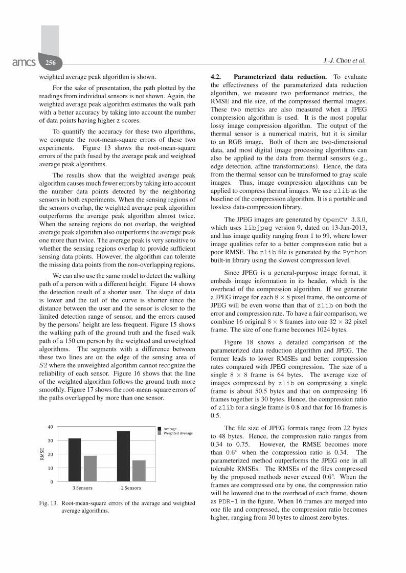
To quantify the accuracy for these two algorithms,we compute the root-mean-square errors of these twoexperiments. Figure 13 shows the root-mean-squareerrors of the path fused by the average peak and weightedaverage peak algorithms.
The results show that the weighted average peakalgorithm causes much fewer errors by taking into accountthe number data points detected by the neighboringsensors in both experiments. When the sensing regions ofthe sensors overlap, the weighted average peak algorithmoutperforms the average peak algorithm almost twice.When the sensing regions do not overlap, the weightedaverage peak algorithm also outperforms the average peakone more than twice. The average peak is very sensitive towhether the sensing regions overlap to provide sufficientsensing data points. However, the algorithm can toleratethe missing data points from the non-overlapping regions.
We can also use the same model to detect the walkingpath of a person with a different height. Figure 14 showsthe detection result of a shorter user. The slope of datais lower and the tail of the curve is shorter since thedistance between the user and the sensor is closer to thelimited detection range of sensor, and the errors causedby the persons’ height are less frequent. Figure 15 showsthe walking path of the ground truth and the fused walkpath of a 150 cm person by the weighted and unweightedalgorithms. The segments with a difference betweenthese two lines are on the edge of the sensing area ofS2 where the unweighted algorithm cannot recognize thereliability of each sensor. Figure 16 shows that the lineof the weighted algorithm follows the ground truth moresmoothly. Figure 17 shows the root-mean-square errors ofthe paths overlapped by more than one sensor.
Fig. 13. Root-mean-square errors of the average and weightedaverage algorithms.
4.2. Parameterized data reduction. To evaluatethe effectiveness of the parameterized data reductionalgorithm, we measure two performance metrics, theRMSE and file size, of the compressed thermal images.These two metrics are also measured when a JPEGcompression algorithm is used. It is the most popularlossy image compression algorithm. The output of thethermal sensor is a numerical matrix, but it is similarto an RGB image. Both of them are two-dimensionaldata, and most digital image processing algorithms canalso be applied to the data from thermal sensors (e.g.,edge detection, affine transformations). Hence, the datafrom the thermal sensor can be transformed to gray scaleimages. Thus, image compression algorithms can beapplied to compress thermal images. We use zlib as thebaseline of the compression algorithm. It is a portable andlossless data-compression library.
The JPEG images are generated by OpenCV 3.3.0,which uses libjpeg version 9, dated on 13-Jan-2013,and has image quality ranging from 1 to 99, where lowerimage qualities refer to a better compression ratio but apoor RMSE. The zlib file is generated by the Pythonbuilt-in library using the slowest compression level.
Since JPEG is a general-purpose image format, itembeds image information in its header, which is theoverhead of the compression algorithm. If we generatea JPEG image for each 8 × 8 pixel frame, the outcome ofJPEG will be even worse than that of zlib on both theerror and compression rate. To have a fair comparison, wecombine 16 original 8 × 8 frames into one 32 × 32 pixelframe. The size of one frame becomes 1024 bytes.
Figure 18 shows a detailed comparison of theparameterized data reduction algorithm and JPEG. Theformer leads to lower RMSEs and better compressionrates compared with JPEG compression. The size of asingle 8 × 8 frame is 64 bytes. The average size ofimages compressed by zlib on compressing a singleframe is about 50.5 bytes and that on compressing 16frames together is 30 bytes. Hence, the compression ratioof zlib for a single frame is 0.8 and that for 16 frames is0.5.
The file size of JPEG formats range from 22 bytesto 48 bytes. Hence, the compression ratio ranges from0.34 to 0.75. However, the RMSE becomes morethan 0.6◦ when the compression ratio is 0.34. Theparameterized method outperforms the JPEG one in alltolerable RMSEs. The RMSEs of the files compressedby the proposed methods never exceed 0.6◦. When theframes are compressed one by one, the compression ratiowill be lowered due to the overhead of each frame, shownas PDR-1 in the figure. When 16 frames are merged intoone file and compressed, the compression ratio becomeshigher, ranging from 30 bytes to almost zero bytes.

IoT sensing networks for gait velocity measurement 257
Elapsed Time (s)
Dis
tan
ce
(c
m)
50
150
250
350
450
550
0 20 40 60
Sensor S1 Sensor S2 Sensor S3 Ground Truth
Fig. 14. Location of 150 cm person with a 170 cm model.
Elapsed Time (s)
Dis
tan
ce
(c
m)
50
150
250
350
450
550
0 20 40 60
Unweighted Weighted Ground Truth
Fig. 15. Location estimated by three sensors of a 150 cm personand location-aware fusion.
Elapsed Time (s)
Dis
tan
ce
(c
m)
50
15
0
25
0
35
0
45
0
55
0
0 20 40 60
Unweighted Weighted Ground Truth
Fig. 16. Location estimated by two sensors of a 150 cm personand location-aware fusion.
5. Conclusion
This paper presented the design, implementation, andevaluation of distributed sensing services using temporaland location properties of sensed data points. Theproposed approach was designed to eliminate the errorscaused by cone shape sensing signals and the height of theperson, which are common for the sensors deployed onthe ceiling and to detect human mobility. The proposedapproach takes advantage of the location framework inWuKong middleware to use one single application for allthe sensing devices in smart homes. It not only measuresgait velocity at a high accuracy, but also reduces thedevelopment and management overhead for distributedsensing services at smart homes.
Acknowledgment
This research was supported in part by the Ministryof Science and Technology of Taiwan (MOST106-2633-E-002-001, MOST 106-2627-M-002-022-),National Taiwan University (NTU-107L104039), IntelCorporation, Delta Electronics, and Advantech.
ReferencesAdministration on Aging (2015). A Profile of Older Amer-
icans: 2015, US Department of Health and HumanServices, https://books.google.com.tw/books?id=B4hEnQAACAAJ.
Alemdar, H. and Ersoy, C. (2010). Wireless sensornetworks for healthcare: A survey, Computer Networks54(15): 2688–2710.
Bourke, A.K., Ihlen, E.A., Van de Ven, P., Nelson, J. andHelbostad, J.L. (2016). Video analysis validation of areal-time physical activity detection algorithm based on asingle waist mounted tri-axial accelerometer sensor, IEEE38th Annual International Conference of the Engineeringin Medicine and Biology Society (EMBC), Orlando, FL,USA, pp. 4881–4884.
Fortino, G., Galzarano, S., Gravina, R. and Li, W. (2015). Aframework for collaborative computing and multi-sensordata fusion in body sensor networks, Information Fusion22: 50–70.
Gheid, Z. and Challal, Y. (2016). Novel efficient andprivacy-preserving protocols for sensor-based humanactivity recognition, 13th International Conference onUbiquitous Intelligence and Computing (UIC 2016),Toulouse, France.
Gravina, R., Ma, C., Pace, P., Aloi, G., Russo, W., Li, W.and Fortino, G. (2017). Cloud-based activity-aaservicecyber-physical framework for human activity monitoringin mobility, Future Generation Computer Systems 75:158–171.
Guo, H. (2011). A simple algorithm for fitting a Gaussianfunction [DSP tips and tricks], IEEE Signal ProcessingMagazine 28(5): 134–137.
Hsu, C.-Y., Liu, Y., Kabelac, Z., Hristov, R., Katabi, D. andLiu, C. (2017). Extracting gait velocity and stride lengthfrom surrounding radio signals, Proceedings of the 2017CHI Conference on Human Factors in Computing Sys-tems, CHI’17, Denver, CO, USA, pp. 2116–2126, DOI:10.1145/3025453.3025937.
Khalajmehrabadi, A., Gatsis, N., Pack, D. and Akopian, D.(2016). A joint indoor WLAN localization and outlierdetection scheme using lasso and elastic-net optimizationtechniques, IEEE Transactions on Mobile ComputingPP(99): 1–1.
Kon, S.S.-C., Jones, S.E., Schofield, S.J., Banya, W., Dickson,M.J., Canavan, J.L., Nolan, C.M., Haselden, B.M.,Polkey, M.I., Cullinan, P. and Man, W.D.-C. (2015). Gaitspeed and readmission following hospitalisation for acuteexacerbations of COPD: A prospective study, Thorax

258 J.-J. Chou et al.
70(12): 1131–1137, http://thorax.bmj.com/content/early/2015/08/17/thoraxjnl-2015-207046.
Kutner, N.G., Zhang, R., Huang, Y. and Painter, P. (2015). Gaitspeed and mortality, hospitalization, and functional statuschange among hemodialysis patients: A US renal datasystem special study, American Journal of Kidney Diseases66(2): 297–304.
Lee, Y.-D. and Chung, W.-Y. (2009). Wireless sensor networkbased wearable smart shirt for ubiquitous health andactivity monitoring, Sensors and Actuators B: Chemical140(2): 390–395.
Lu, C.H. and Fu, L.C. (2009). Robust location-aware activityrecognition using wireless sensor network in an attentivehome, IEEE Transactions on Automation Science and En-gineering 6(4): 598–609.
Middleton, A., Fritz, S.L. and Lusardi, M. (2015). Walkingspeed: The functional vital sign, Journal of Aging andPhysical Activity 23(2): 314–322.
Milenkovic, A., Otto, C. and Jovanov, E. (2006). Wirelesssensor networks for personal health monitoring: Issuesand an implementation, Computer Communications29(13–14): 2521–2533.
Peters, D.M., Middleton, A., Donley, J.W., Blanck, E.L. andFritz, S.L. (2014). Concurrent validity of walking speedvalues calculated via the gaitrite electronic walkway and3 meter walk test in the chronic stroke population, Phys-iotherapy Theory and Practice 30(3): 183–188, DOI:10.3109/09593985.2013.845805.
Pulignano, G., Del Sindaco, D., Di Lenarda, A., Alunni, G.,Senni, M., Tarantini, L., Cioffi, G., Tinti, M., Barbati, G.,Minardi, G. and Uguccioni, M. (2016). Incremental valueof gait speed in predicting prognosis of older adults withheart failure: Insights from the IMAGE-HF study, JACCHeart Failure 4(4): 289–298.
Reijers, N., Lin, K.-J., Wang, Y.-C., Shih, C.-S. and Hsu, J.Y.(2013). Design of an intelligent middleware for flexiblesensor configuration in M2M systems, Proceedings of the2nd International Conference on Sensor Networks (SEN-SORNETS), Barcelona, Spain, pp. 1–6.
Reijers, N. and Shih, C.-S. (2017). Ahead-of-time compilationof stack-based JVM bytecode on resource-constraineddevices, Proceedings of 2017 International Conference onEmbedded Wireless Systems and Networks (EWSN), Upp-sala, Sweden, pp. 1–12.
Shih, C.-S. (2016). WuKong Release Document 0.4, https://www.gitbook.com/book/wukongsun/wukong-release-0-4/details.
Shih, C.-S., Chou, J.-J., Chuang, C.-C., Wang, T.-Y., Chuang,Z.-Y., Lin, K.-J., Wang, W.-D. and Huang, K.-C. (2017).Collaborative sensing for privacy preserving gait trackingusing IoT middleware, 2017 International Conference onResearch in Adaptive and Convergent Systems (RACS2017), Krakow, Poland, pp. 152–159.
Studenski, S., Perera, S., Patel, K., Rosano, C., Faulkner, K.,Inzitari, M., Brach, J., Chandler, J., Cawthon, P., Connor,
Fig. 17. Root mean square errors of average and weightedaverage algorithms on a 150 cm person.
0
0.2
0.4
0.6
0.8
1
1.2
1.4
1.6
1.8
0 10 20 30 40 50 60
RMSE
(�
)
Average Frame Size (Byte)
PDR-1PDR-16JPG-16
zlib-1zlib-16
Fig. 18. Comparison of error rates and the compression ratio.
E.B., Nevitt, M., Visser, M., Kritchevsky, S., Badinelli,S., Harris, T., Newman, A.B., Cauley, J., Ferrucci, L.and Guralnik, J. (2011). Gait speed and survival inolder adults, Journal of the American Medical Association305(1): 50–58.
Studenski, S., Perera, S., Wallace, D., Chandler, J.M.,Duncan, P.W., Rooney, E., Fox, M. and Guralnik,J.M. (2003). Physical performance measures in theclinical setting, Journal of the American Geriatrics Society51(3): 314–322, DOI: 10.1046/j.1532-5415.2003.51104.x.
USRP N210 (2019). Software Defined Radio (SDR), EttusResearch, https://www.ettus.com/product/details/UN210-KIT.
WuKong (2012). Software repository, https://github.com/wukong-m2m/wukong-darjeeling.
Yi, X., Willemson, J. and Nait-Abdesselam, F. (2013).Privacy-preserving wireless medical sensor network, 201312th IEEE International Conference on Trust, Security andPrivacy in Computing and Communications, Melbourne,Australia, pp. 118–125.

IoT sensing networks for gait velocity measurement 259
Zhao, M., Adib, F. and Katabi, D. (2016). Emotion recognitionusing wireless signals, Proceedings of the 22nd AnnualInternational Conference on Mobile Computing and Net-working, MobiCom’16, New York, NY, USA, pp. 95–108,DOI: 10.1145/2973750.2973762.
Chi-Sheng Shih received his BSc in engineer-ing science and his MSc in computer sciencefrom National Cheng Kung University in 1993and 1995, respectively. He joined National Tai-wan University in 2004 and has been a professorsince 2018. His main research interests includeembedded systems, hardware/software codesign,real-time systems, and database systems. Specif-ically, his main research interests focus on real-time operating systems, real-time scheduling the-
ory, embedded software, and software/hardware co-design for system-on-a-chip. His research results have won several awards. He has alsoserved on steering committees of several international conferences andon editorial boards of international journals.
Jyun-Jhe Chou received his Bachelor’s degreein computer science and information engineer-ing at National Taiwan University in 2014, andis now a PhD candidate. His research interestsinclude the Internet of things, data quality, andcyber-physical systems.
Wei-Dean Wang received his MD degreefrom Taipei Medical University, Taiwan, in 1982and his PhD degree in medical education fromNational Taiwan Normal University in 2003.He completed the residency training in familymedicine at the Kansas University Medical Cen-ter in 1989, and has been the Diplomate of Fam-ily Medicine of the American Board of FamilyMedicine since 1989. His research interests aremainly in medical education, family medicine,
elderly care, and international medicine. His current research coversvarious issues regarding medical and home care for dwelling elderly athome.
Kuo-Chin Huang has been the superintendentof the National Taiwan University Hospital, Bei-Hu Branch, Taipei, Taiwan, since 2015 and a pro-fessor with the Department of Family Medicine,College of Medicine, National Taiwan Univer-sity, Taipei, since 2009. He holds MD and PhDdegrees from National Taiwan University, andhad conducted his post doc at the University ofSydney.
Received: 1 July 2018Revised: 11 March 2019Accepted: 21 March 2019


![Click Here Full Article Remote sensing of suspended ... · PDF fileRemote sensing of suspended sediment concentration, flow velocity, ... [Maidment, 1993]. In particular, a relationship](https://img.pdfslide.net/doc/110x75/5a79f9107f8b9ae67b8df3a5/click-here-full-article-remote-sensing-of-suspended-sensing-of-suspended-sediment.jpg)