Embed Size (px)
Citation preview
2009 copyright by Burt H. Liebowitz Slide 1
IP NETWORKING OVER SATELLITE
Burt H. LiebowitzATI Three-Day SeminarGeneral DynamicsScottsdale, ArizonaJanuary 23-25, 2008
Global Internet
Throughput vs. Round Trip Delay with Window Size as a Parameter
0200400600800
100012001400160018002000
0.1 0.2 0.3 0.4 0.5 0.6 0.7 0.8 0.9 1.0
Round Trip Delay in Seconds
Effe
ctiv
e Th
roug
hput
in K
bps
40968192163843276865536
window sizein bytes
For Government, Military and Commercial Enterprises
Applied Technology Institute 349 Berkshire Drive Riva, Maryland 21140 888-501-2100/410-956-8805 Website: www.ATIcourses.com Email: [email protected]
ATI Course Schedule: http://www.ATIcourses.com/schedule.htm ATI’s IP Networking Over Satellite: http://www.ATIcourses.com/internet_over_satellite.htm

www.ATIcourses.com
Boost Your Skills with On-Site Courses Tailored to Your Needs The Applied Technology Institute specializes in training programs for technical professionals. Our courses keep you current in the state-of-the-art technology that is essential to keep your company on the cutting edge in today’s highly competitive marketplace. Since 1984, ATI has earned the trust of training departments nationwide, and has presented on-site training at the major Navy, Air Force and NASA centers, and for a large number of contractors. Our training increases effectiveness and productivity. Learn from the proven best. For a Free On-Site Quote Visit Us At: http://www.ATIcourses.com/free_onsite_quote.asp For Our Current Public Course Schedule Go To: http://www.ATIcourses.com/schedule.htm
2/23/2009 copyright by Burt H. Liebowitz Slide 2
Burt H. Liebowitz is a Principal Engineer at the MITRE Corporation responsible for the economic and technical analysis of wireless systems. He has more than 30 years experience in computer networking, most recently with Internet-over-satellite services. He has served as a consultant to leading companies providing such services. He was President of NetSat Express, and before that Chief Technical Officer for Loral Orion, responsible for satellite-based networking products. Mr. Liebowitz has authored two books on distributed processing, written numerous articles on computing and communications systems, and lectured extensively on computer networking. He holds three patents for satellite-based data networking systems. Mr. Liebowitz has B.E.E. and M.S. in Math degrees from Rensselaer Polytechnic Institute, and an M.S.E.E. from Polytechnic Institute of Brooklyn.
Telephone Number – 703 983 4533Email: [email protected]
The content herein is solely the work of the author and does not represent the viewpoints or opinions of the MITRE
Corporation
2/23/2009 copyright by Burt H. Liebowitz Slide 3
Seminar Outline1- Introduction and Purpose2- Fundamentals of Data Networking3- The Internet and Its Protocols4- Quality of Service Issues in IP Networks5- Satellite Data Networking Architecture6- System Design and Economic Issues for
Satellite-Based IP Networks7- TDMA/DAMA Design Example8- Predicting Performance in Mission-Critical
Networks9- Conclusions and a View of the FutureBibliography and Table of Acronyms
2/23/2009 copyright by Burt H. Liebowitz Slide 4
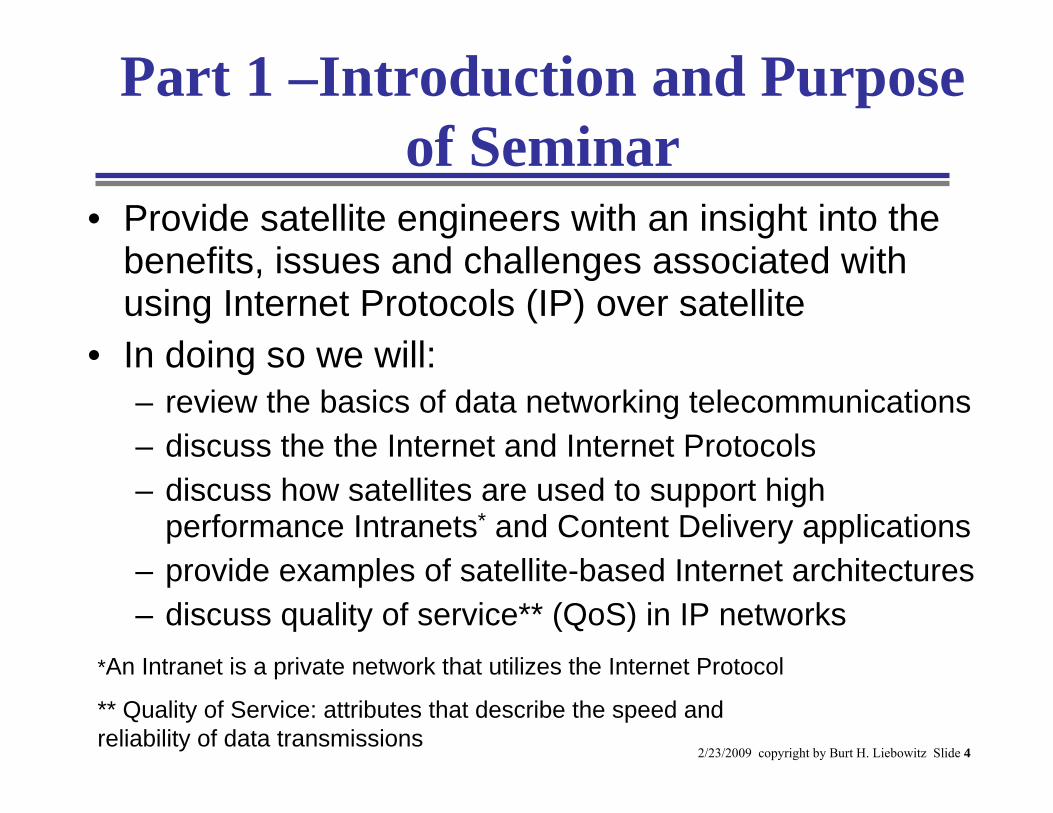
Part 1 –Introduction and Purpose of Seminar
• Provide satellite engineers with an insight into the benefits, issues and challenges associated with using Internet Protocols (IP) over satellite
• In doing so we will:– review the basics of data networking telecommunications– discuss the the Internet and Internet Protocols– discuss how satellites are used to support high
performance Intranets* and Content Delivery applications– provide examples of satellite-based Internet architectures– discuss quality of service** (QoS) in IP networks
*An Intranet is a private network that utilizes the Internet Protocol
** Quality of Service: attributes that describe the speed and reliability of data transmissions
2/23/2009 copyright by Burt H. Liebowitz Slide 5
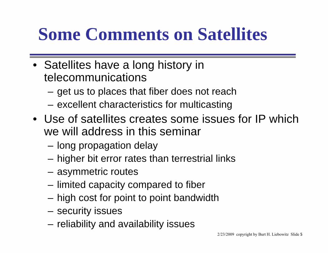
Some Comments on Satellites• Satellites have a long history in
telecommunications– get us to places that fiber does not reach– excellent characteristics for multicasting
• Use of satellites creates some issues for IP which we will address in this seminar– long propagation delay– higher bit error rates than terrestrial links– asymmetric routes– limited capacity compared to fiber– high cost for point to point bandwidth– security issues– reliability and availability issues
2/23/2009 copyright by Burt H. Liebowitz Slide 6
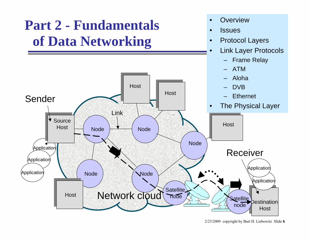
Part 2 - Fundamentals of Data Networking
Sender
Receiver
Network cloud
Application
Link
Application
Application
Host
Satellitenode
HostNode
Node
Node
Node
Node
Source Host
HostHostDestination
HostDestination
Host
Satellitenode
Application
Application
Host
• Overview• Issues• Protocol Layers• Link Layer Protocols
– Frame Relay– ATM– Aloha– DVB– Ethernet
• The Physical Layer
2/23/2009 copyright by Burt H. Liebowitz Slide 7
Data Networking• Data networks are used to transmit digital data
from one point to another– A session is a two-way flow of digital data between
two applications in different host computers• Each flow represents a one-way transfer of a message from
one application to another along a path in the network• Each message is broken into units of transfer called packets• A packet consists of a header, payload and trailer
• Digital networks were developed to transmit computer files– can also be used for voice and video, since analog
signals can be digitized
2/23/2009 copyright by Burt H. Liebowitz Slide 8
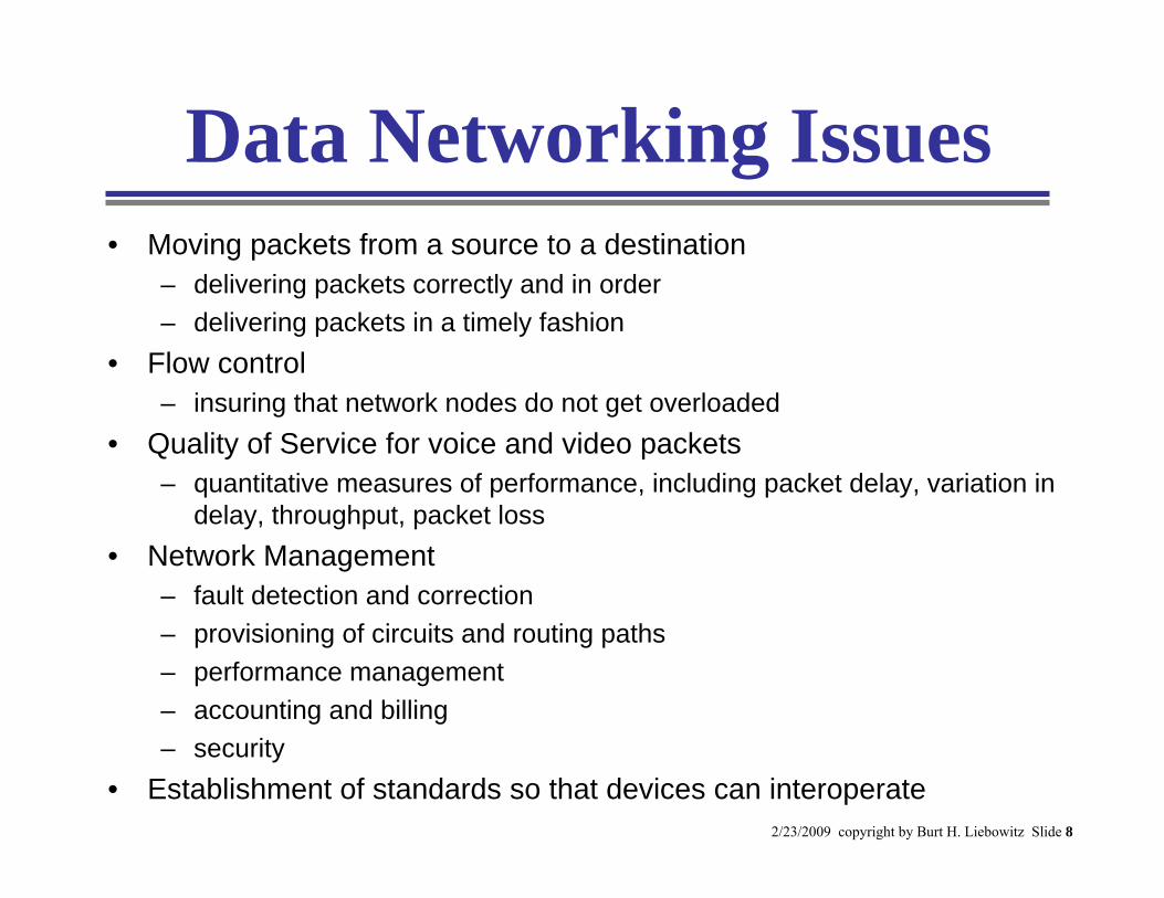
Data Networking Issues• Moving packets from a source to a destination
– delivering packets correctly and in order– delivering packets in a timely fashion
• Flow control– insuring that network nodes do not get overloaded
• Quality of Service for voice and video packets– quantitative measures of performance, including packet delay, variation in
delay, throughput, packet loss• Network Management
– fault detection and correction– provisioning of circuits and routing paths– performance management– accounting and billing– security
• Establishment of standards so that devices can interoperate
2/23/2009 copyright by Burt H. Liebowitz Slide 9
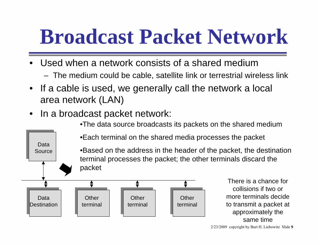
Broadcast Packet Network• Used when a network consists of a shared medium
– The medium could be cable, satellite link or terrestrial wireless link
• If a cable is used, we generally call the network a local area network (LAN)
• In a broadcast packet network:
Data Destination
Data Source
Other terminal
Other terminal
Other terminal
•The data source broadcasts its packets on the shared medium
•Each terminal on the shared media processes the packet
•Based on the address in the header of the packet, the destination terminal processes the packet; the other terminals discard the packet
There is a chance for collisions if two or
more terminals decide to transmit a packet at
approximately the same time
2/23/2009 copyright by Burt H. Liebowitz Slide 10
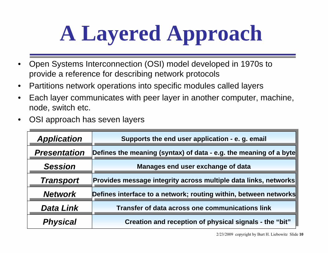
A Layered Approach• Open Systems Interconnection (OSI) model developed in 1970s to
provide a reference for describing network protocols• Partitions network operations into specific modules called layers• Each layer communicates with peer layer in another computer, machine,
node, switch etc.• OSI approach has seven layers
ApplicationApplicationPresentationPresentation
SessionSessionTransportTransportNetworkNetworkData LinkData LinkPhysicalPhysical
Supports the end user application - e. g. emailSupports the end user application - e. g. email
Defines the meaning (syntax) of data - e.g. the meaning of a byteDefines the meaning (syntax) of data - e.g. the meaning of a byte
Manages end user exchange of dataManages end user exchange of data
Provides data integrity across multiple data links and networksProvides data integrity across multiple data links and networks
Defines interface to a network; routing within, between networksDefines interface to a network; routing within, between networks
Transfer of data across one communications linkTransfer of data across one communications link
creation and reception of physical signals creation and reception of physical signals
Supports the end user application - e. g. emailSupports the end user application - e. g. emailDefines the meaning (syntax) of data - e.g. the meaning of a byteDefines the meaning (syntax) of data - e.g. the meaning of a byte
Manages end user exchange of dataManages end user exchange of dataProvides message integrity across multiple data links, networksProvides message integrity across multiple data links, networksDefines interface to a network; routing within, between networksDefines interface to a network; routing within, between networks
Transfer of data across one communications linkTransfer of data across one communications linkCreation and reception of physical signals - the “bit”Creation and reception of physical signals - the “bit”
2/23/2009 copyright by Burt H. Liebowitz Slide 11
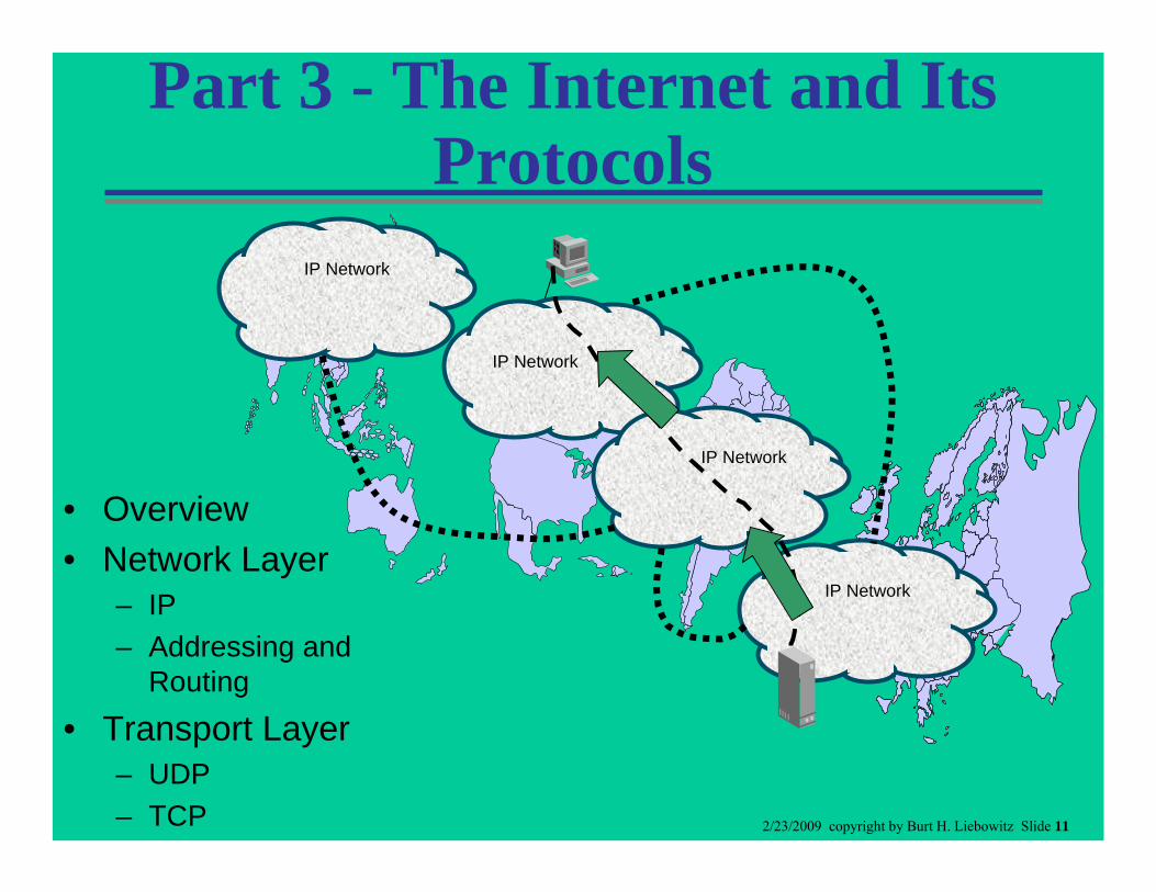
Part 3 - The Internet and Its Protocols
IP Network
IP Network
IP Network
IP Network
• Overview• Network Layer
– IP– Addressing and
Routing
• Transport Layer– UDP– TCP
2/23/2009 copyright by Burt H. Liebowitz Slide 12
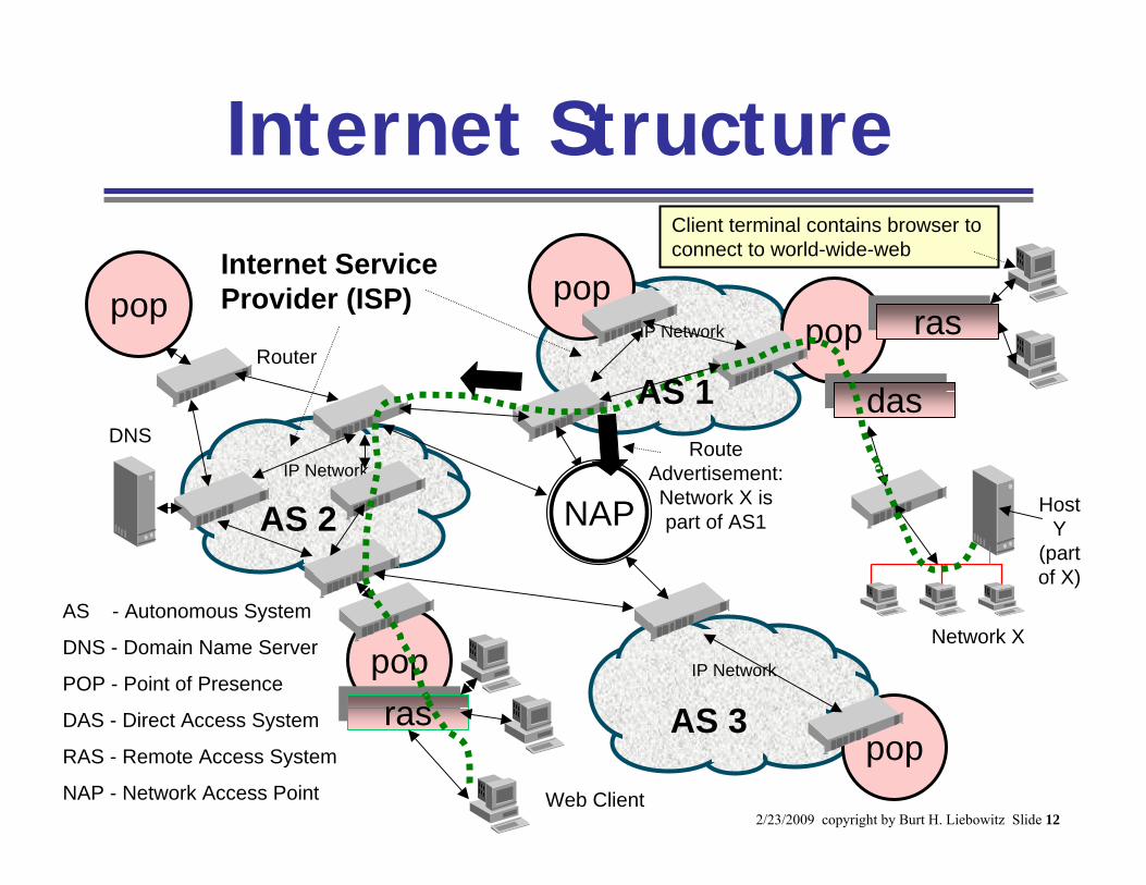
pop
Internet Structure
IP Network
IP Network
IP Network
Router
pop poppop
rasras
dasdas
NAP
pop
rasras
AS - Autonomous System
DNS - Domain Name Server
POP - Point of Presence
DAS - Direct Access System
RAS - Remote Access System
NAP - Network Access Point
Host Y
(part of X)
Web Client
DNS
Client terminal contains browser to connect to world-wide-webInternet Service
Provider (ISP)
AS 1
AS 3
AS 2
Network X
Route Advertisement: Network X is part of AS1
2/23/2009 copyright by Burt H. Liebowitz Slide 13
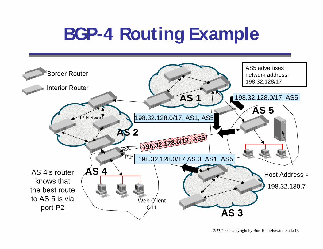
BGP-4 Routing Example
IP Network
IP Network
Host Address =
198.32.130.7
Web Client C11
AS 2
AS 3
AS 4
AS 5AS 1 198.32.128.0/17, AS5
198.32.128.0/17 AS 3, AS1, AS5P1P2
AS 4’s router knows that
the best route to AS 5 is via
port P2
198.32.128.0/17, AS5
AS5 advertises network address: 198.32.128/17
198.32.128.0/17, AS1, AS5
Border Router
Interior Router
2/23/2009 copyright by Burt H. Liebowitz Slide 14
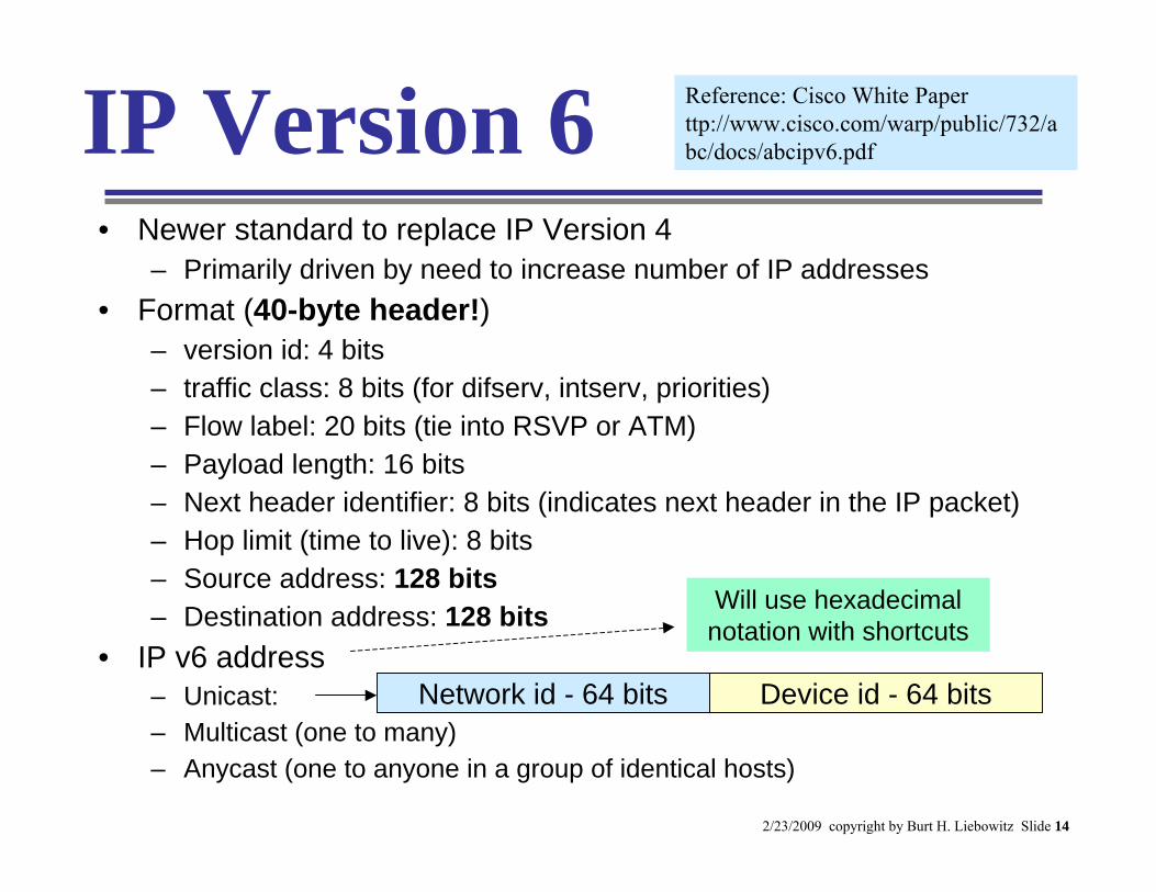
IP Version 6• Newer standard to replace IP Version 4
– Primarily driven by need to increase number of IP addresses • Format (40-byte header!)
– version id: 4 bits– traffic class: 8 bits (for difserv, intserv, priorities)– Flow label: 20 bits (tie into RSVP or ATM)– Payload length: 16 bits– Next header identifier: 8 bits (indicates next header in the IP packet)– Hop limit (time to live): 8 bits– Source address: 128 bits– Destination address: 128 bits
• IP v6 address– Unicast:– Multicast (one to many)– Anycast (one to anyone in a group of identical hosts)
Reference: Cisco White Paper ttp://www.cisco.com/warp/public/732/abc/docs/abcipv6.pdf
Device id - 64 bitsNetwork id - 64 bits
Will use hexadecimal notation with shortcuts
2/23/2009 copyright by Burt H. Liebowitz Slide 15
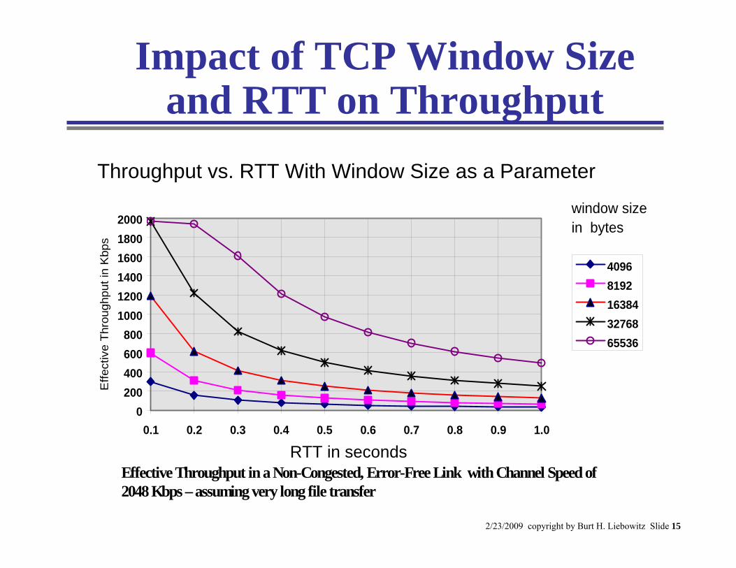
Impact of TCP Window Size and RTT on Throughput
Throughput vs. Round Trip Delay with Window Size as a Parameter
0200400600800
100012001400160018002000
0.1 0.2 0.3 0.4 0.5 0.6 0.7 0.8 0.9 1.0
Round Trip Delay in Seconds
Effe
ctiv
e Th
roug
hput
in K
bps
40968192163843276865536
window sizein bytes
Effective Throughput in a Non-Congested, Error-Free Link with Channel Speed of2048 Kbps – assuming very long file transfer
Throughput vs. RTT With Window Size as a Parameter
RTT in seconds
2/23/2009 copyright by Burt H. Liebowitz Slide 16
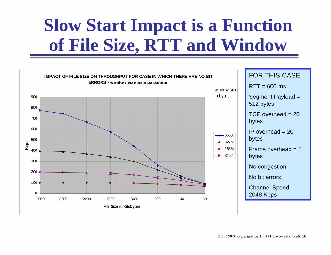
Slow Start Impact is a Function of File Size, RTT and Window
FOR THIS CASE:RTT = 600 ms
Segment Payload = 512 bytes
TCP overhead = 20 bytes
IP overhead = 20 bytes
Frame overhead = 5 bytes
No congestion
No bit errors
Channel Speed -2048 Kbps
IMPACT OF FILE SIZE ON THROUGHPUT FOR CASE IN WHICH THERE ARE NO BIT ERRORS - window size as a parameter
0
100
200
300
400
500
600
700
800
900
10000 5000 2000 1000 500 200 100 50
File Size in Kilobytes
Kbps
65536
32768
16384
8192
window size in bytes
2/23/2009 copyright by Burt H. Liebowitz Slide 17
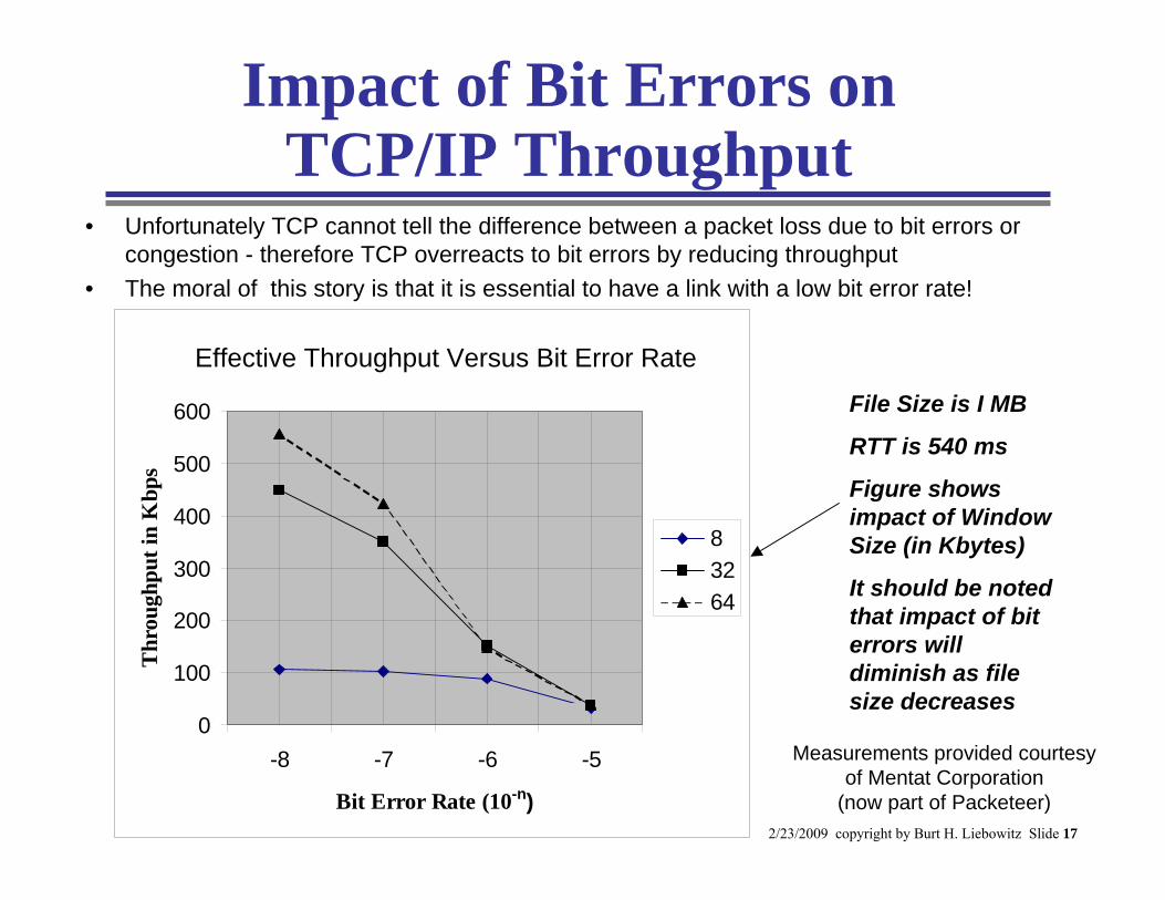
Impact of Bit Errors on TCP/IP Throughput
File Size is I MB
RTT is 540 ms
Figure shows impact of Window Size (in Kbytes)
It should be noted that impact of bit errors will diminish as file size decreases
Measurements provided courtesy of Mentat Corporation
(now part of Packeteer)
• Unfortunately TCP cannot tell the difference between a packet loss due to bit errors or congestion - therefore TCP overreacts to bit errors by reducing throughput
• The moral of this story is that it is essential to have a link with a low bit error rate!
-8 -7 -6 -5
Bit Error Rate (10-n)
Effect of Bit Errors on Throughput
0
100
200
300
400
500
600
-8 -7 -6 -5
Bit Error Rate (10-n)
Thr
ough
put i
n K
bps
83264
Effective Throughput Versus Bit Error Rate
2/23/2009 copyright by Burt H. Liebowitz Slide 18
Part 4 - Quality of Service (QoS) Issues in IP Networks
This Section Discusses• QoS requirements for inelastic flows
such as voice and video• Response time for elastic, web-
based file transfers• General methods available to
support QoS in IP Networks• Network Management
– Monitoring– Security
QoS: the ability of a network to deliver
packets within specified metrics including packet
loss, delay, jitter.
QoS: the ability of a network to deliver
packets within specified metrics including packet
loss, delay, jitter.
2/23/2009 copyright by Burt H. Liebowitz Slide 19
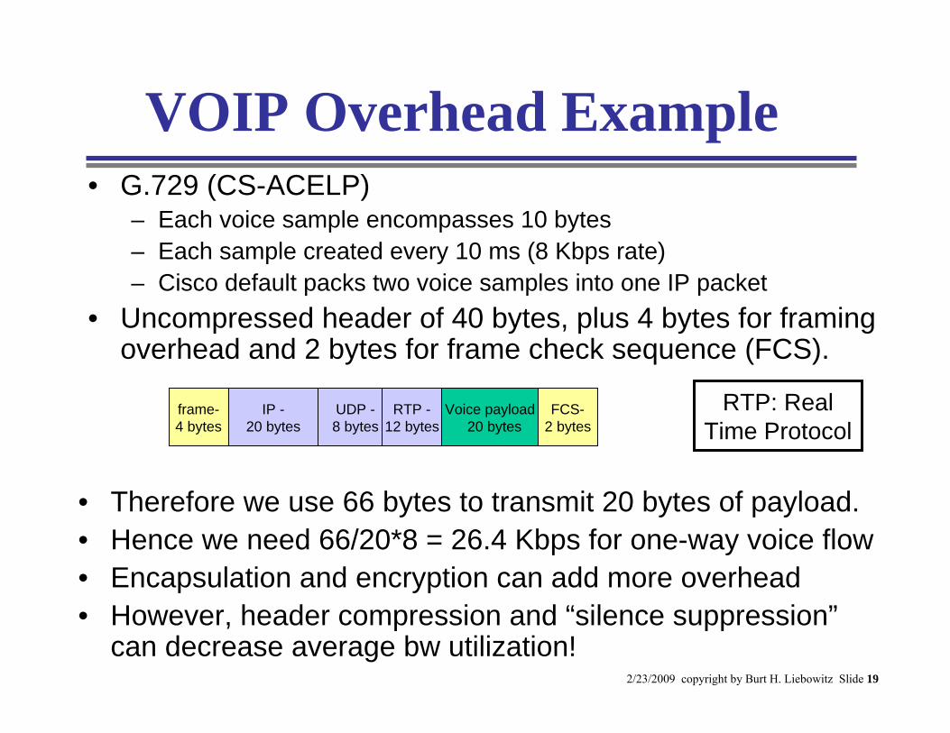
VOIP Overhead Example • G.729 (CS-ACELP)
– Each voice sample encompasses 10 bytes– Each sample created every 10 ms (8 Kbps rate)– Cisco default packs two voice samples into one IP packet
• Uncompressed header of 40 bytes, plus 4 bytes for framing overhead and 2 bytes for frame check sequence (FCS).
• Therefore we use 66 bytes to transmit 20 bytes of payload.• Hence we need 66/20*8 = 26.4 Kbps for one-way voice flow• Encapsulation and encryption can add more overhead• However, header compression and “silence suppression”
can decrease average bw utilization!
IP -20 bytes
UDP -8 bytes
RTP -12 bytes
Voice payload -20 bytes
frame-4 bytes
FCS-2 bytes
RTP: RealTime Protocol
2/23/2009 copyright by Burt H. Liebowitz Slide 20
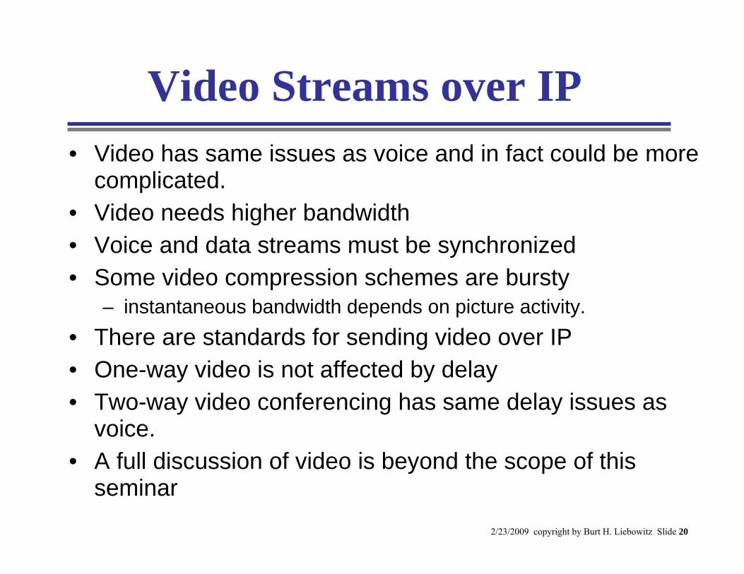
Video Streams over IP• Video has same issues as voice and in fact could be more
complicated.• Video needs higher bandwidth• Voice and data streams must be synchronized• Some video compression schemes are bursty
– instantaneous bandwidth depends on picture activity.• There are standards for sending video over IP• One-way video is not affected by delay • Two-way video conferencing has same delay issues as
voice.• A full discussion of video is beyond the scope of this
seminar
2/23/2009 copyright by Burt H. Liebowitz Slide 21
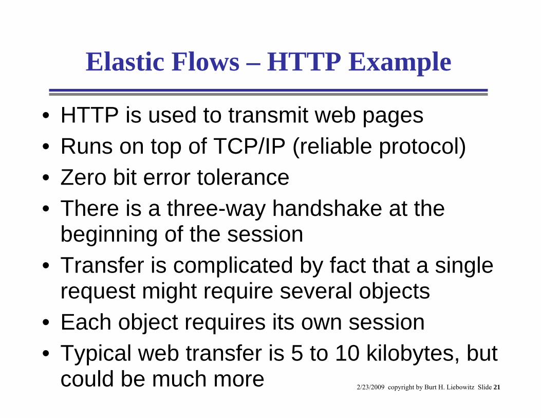
Elastic Flows – HTTP Example
• HTTP is used to transmit web pages• Runs on top of TCP/IP (reliable protocol)• Zero bit error tolerance• There is a three-way handshake at the
beginning of the session• Transfer is complicated by fact that a single
request might require several objects• Each object requires its own session• Typical web transfer is 5 to 10 kilobytes, but
could be much more
2/23/2009 copyright by Burt H. Liebowitz Slide 22
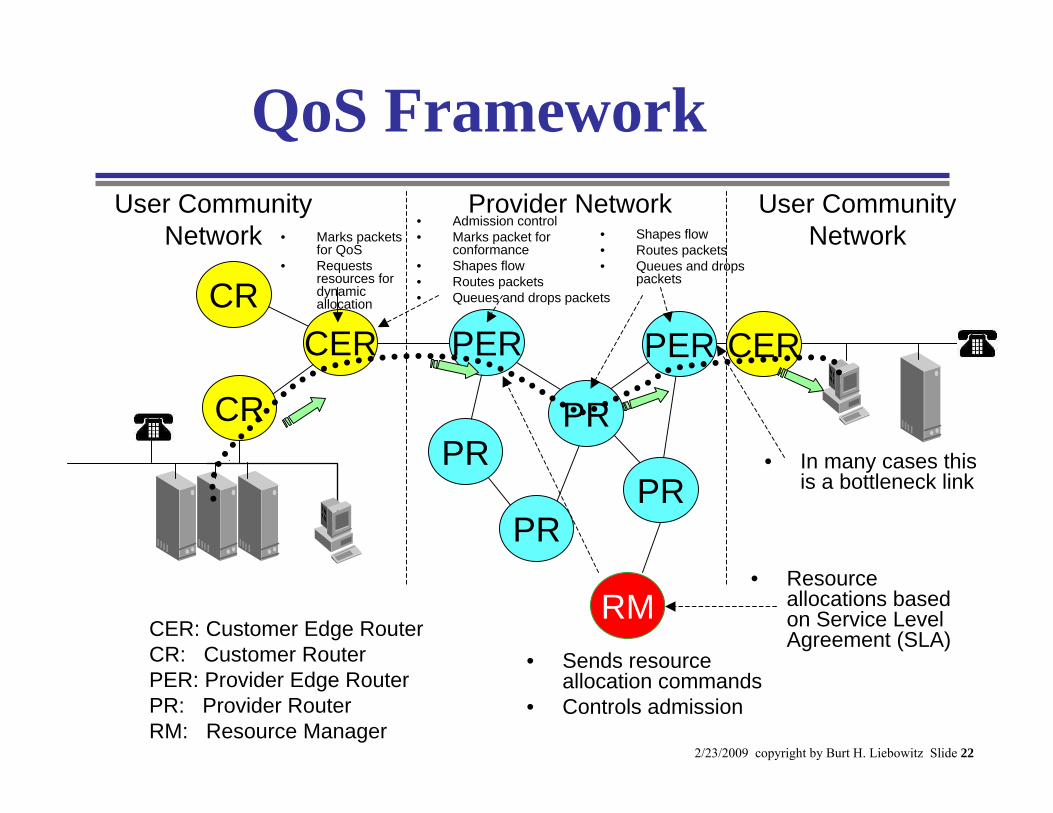
QoS Framework
CER: Customer Edge RouterCR: Customer RouterPER: Provider Edge RouterPR: Provider RouterRM: Resource Manager
• Resource allocations based on Service Level Agreement (SLA)
• Sends resource allocation commands
• Controls admission
User Community Network
Provider Network User Community Network
CER PER
PR
PER
PR
PR
PR
CER
CR
CR
RM
• Shapes flow• Routes packets• Queues and drops
packets
• Marks packets for QoS
• Requests resources for dynamic allocation
• Admission control• Marks packet for
conformance• Shapes flow• Routes packets• Queues and drops packets
• In many cases this is a bottleneck link
2/23/2009 copyright by Burt H. Liebowitz Slide 23
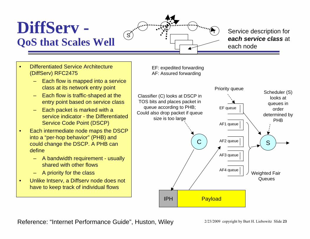
DiffServ -QoS that Scales Well
• Differentiated Service Architecture (DiffServ) RFC2475
– Each flow is mapped into a service class at its network entry point
– Each flow is traffic-shaped at the entry point based on service class
– Each packet is marked with a service indicator - the Differentiated Service Code Point (DSCP)
• Each intermediate node maps the DSCP into a “per-hop behavior” (PHB) and could change the DSCP. A PHB can define
– A bandwidth requirement - usually shared with other flows
– A priority for the class• Unlike Intserv, a Diffserv node does not
have to keep track of individual flows
Reference: “Internet Performance Guide”, Huston, Wiley
Sr Service description for
each service class at each node
S
AF1 queue
AF2 queue
AF3 queue
EF queue
AF4 queue
C
IPH Payload
Priority queue
Weighted Fair Queues
Classifier (C) looks at DSCP in TOS bits and places packet in
queue according to PHB;Could also drop packet if queue
size is too large
Scheduler (S) looks at
queues in order
determined by PHB
EF: expedited forwardingAF: Assured forwarding
2/23/2009 copyright by Burt H. Liebowitz Slide 24
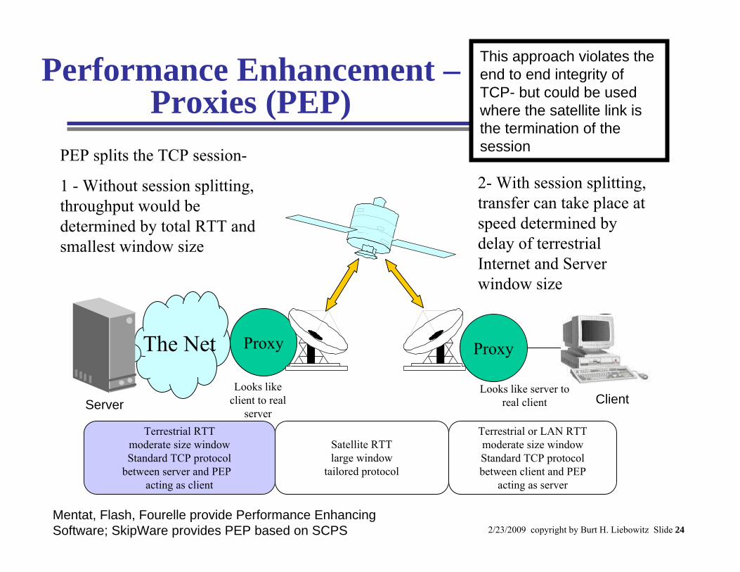
Performance Enhancement –Proxies (PEP)
Proxy Client
Terrestrial RTTmoderate size windowStandard TCP protocol
between server and PEP acting as client
Satellite RTTlarge window
tailored protocol
Terrestrial or LAN RTTmoderate size windowStandard TCP protocolbetween client and PEP
acting as server
PEP splits the TCP session-
1 - Without session splitting, throughput would be determined by total RTT and smallest window size
2- With session splitting, transfer can take place at speed determined by delay of terrestrial Internet and Server window size
Looks like client to real
server
Looks like server to real client Client
ProxyThe Net
Server
This approach violates the end to end integrity of TCP- but could be used where the satellite link is the termination of the session
Mentat, Flash, Fourelle provide Performance Enhancing Software; SkipWare provides PEP based on SCPS
2/23/2009 copyright by Burt H. Liebowitz Slide 25
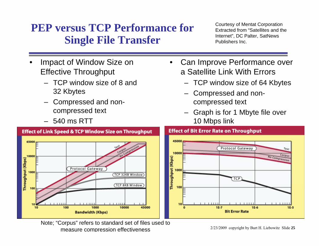
PEP versus TCP Performance for Single File Transfer
Courtesy of Mentat CorporationExtracted from “Satellites and the Internet”, DC Palter, SatNews Publishers Inc.
Note; “Corpus” refers to standard set of files used to measure compression effectiveness
• Impact of Window Size on Effective Throughput – TCP window size of 8 and
32 Kbytes– Compressed and non-
compressed text– 540 ms RTT
• Can Improve Performance over a Satellite Link With Errors– TCP window size of 64 Kbytes– Compressed and non-
compressed text– Graph is for 1 Mbyte file over
10 Mbps link
2/23/2009 copyright by Burt H. Liebowitz Slide 26
IPsec Modes of Service• Transport (Tactical*)
– Original IP header in the clear, rest of packet is encrypted and authenticated
• Encryption provided at host location– Encryption negotiated between hosts
• Tunnel (Strategic*)– Original IP packet is encrypted including header
• Encryption and new header is provided at tunnel end point (router)
– tunnel negotiated between end points associated with networks
*“Tactical” and “Strategic” are terms
used in HAIPE
router router
Routers create tunnel and perform encryption
IP NetworkClear Clear
EncryptedEncrypted
2/23/2009 copyright by Burt H. Liebowitz Slide 27
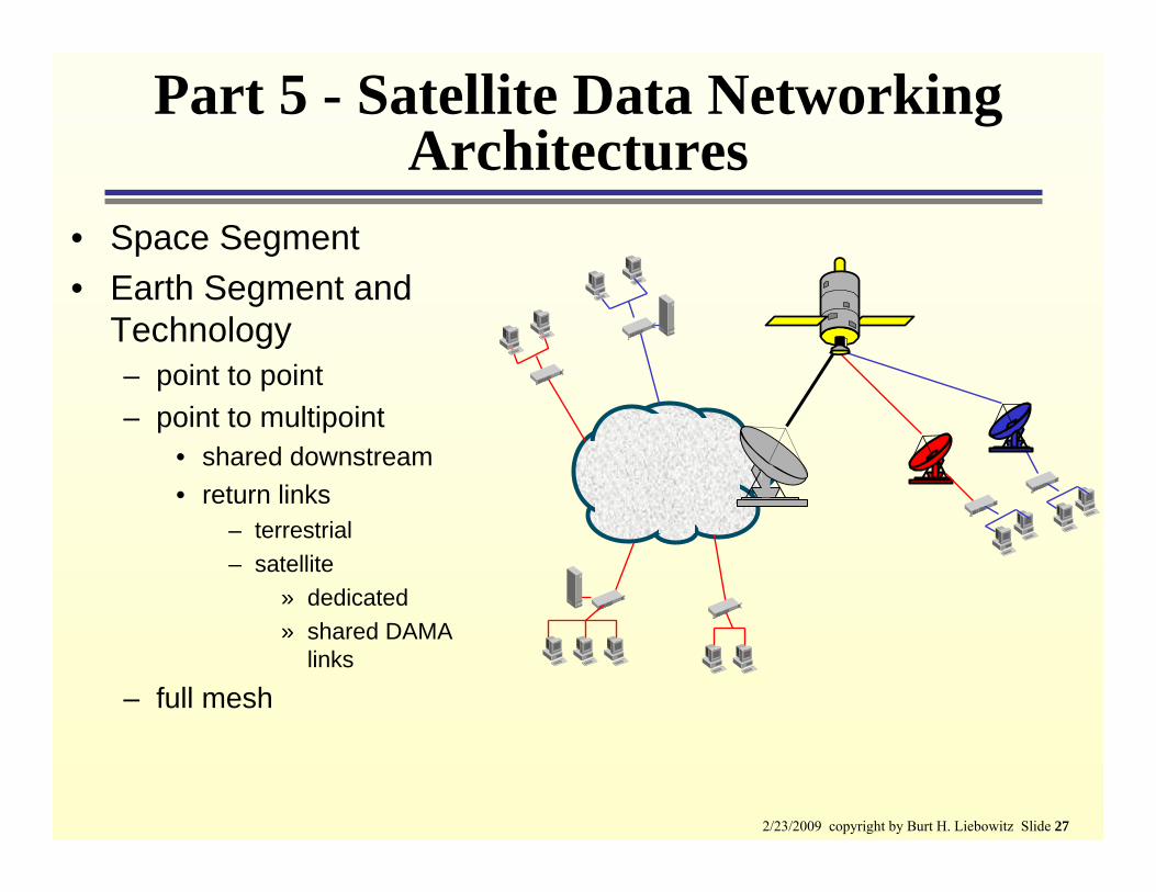
Part 5 - Satellite Data Networking Architectures
• Space Segment• Earth Segment and
Technology– point to point– point to multipoint
• shared downstream• return links
– terrestrial– satellite
» dedicated» shared DAMA
links
– full mesh
2/23/2009 copyright by Burt H. Liebowitz Slide 28
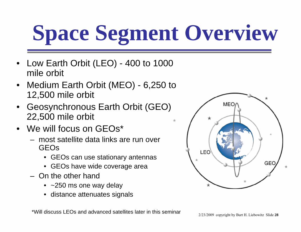
Space Segment Overview• Low Earth Orbit (LEO) - 400 to 1000
mile orbit• Medium Earth Orbit (MEO) - 6,250 to
12,500 mile orbit• Geosynchronous Earth Orbit (GEO) -
22,500 mile orbit• We will focus on GEOs*
– most satellite data links are run over GEOs
• GEOs can use stationary antennas• GEOs have wide coverage area
– On the other hand• ~250 ms one way delay• distance attenuates signals
*Will discuss LEOs and advanced satellites later in this seminar
2/23/2009 copyright by Burt H. Liebowitz Slide 29
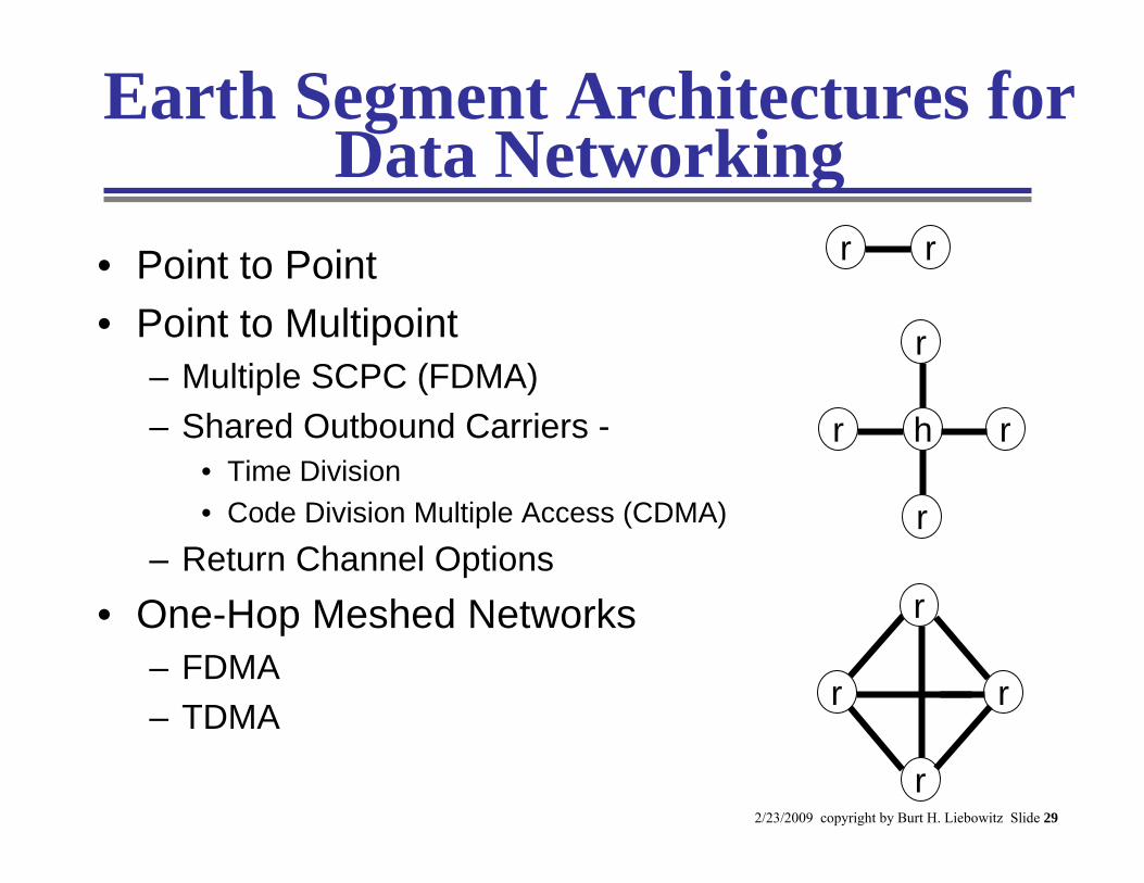
Earth Segment Architectures for Data Networking
• Point to Point• Point to Multipoint
– Multiple SCPC (FDMA)– Shared Outbound Carriers -
• Time Division• Code Division Multiple Access (CDMA)
– Return Channel Options• One-Hop Meshed Networks
– FDMA– TDMA
h
r
r r
r
r
r
r
r
rr
2/23/2009 copyright by Burt H. Liebowitz Slide 30
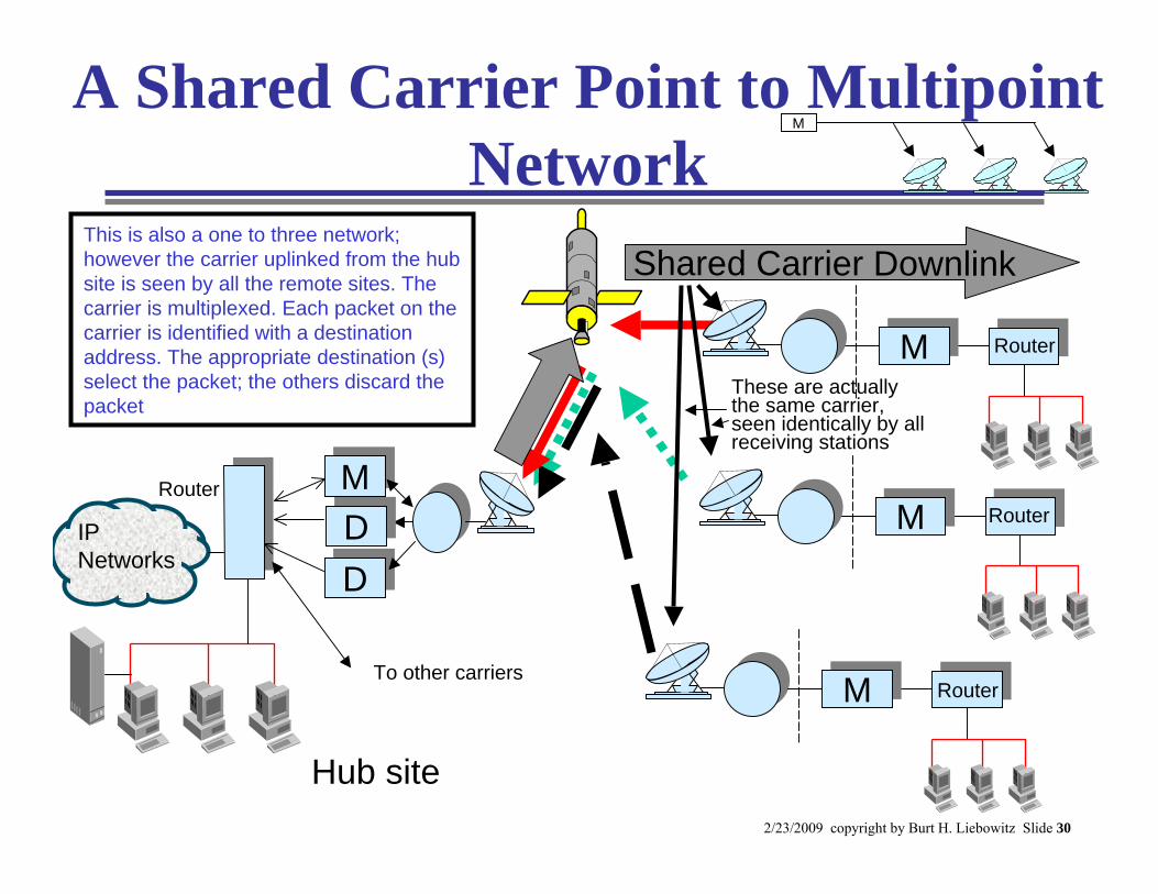
A Shared Carrier Point to Multipoint Network
Router
This is also a one to three network; however the carrier uplinked from the hub site is seen by all the remote sites. The carrier is multiplexed. Each packet on the carrier is identified with a destination address. The appropriate destination (s) select the packet; the others discard the packet
Shared Carrier Downlink
These are actually the same carrier, seen identically by all receiving stations
Hub site
M
MM Router
MM Router
MM Router
DD
MM
DDIP Networks
To other carriers
2/23/2009 copyright by Burt H. Liebowitz Slide 31
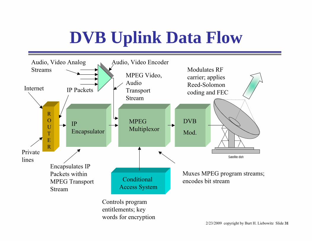
DVB Uplink Data Flow
ROUTER
IPEncapsulator
MPEG Multiplexor
DVB
Mod.
Modulates RF carrier; applies Reed-Solomon coding and FEC
Conditional Access System
Muxes MPEG program streams; encodes bit stream
Encapsulates IP Packets within MPEG Transport Stream
IP Packets
MPEG Video, Audio Transport Stream
Internet
Private lines
Controls program entitlements; key words for encryption
Satellite dish
Audio, Video EncoderAudio, Video Analog Streams
2/23/2009 copyright by Burt H. Liebowitz Slide 32
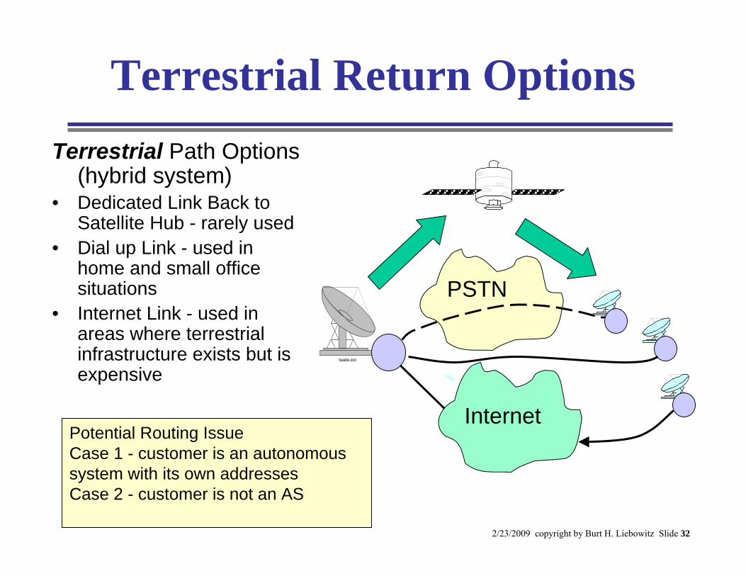
Terrestrial Return OptionsTerrestrial Path Options
(hybrid system)• Dedicated Link Back to
Satellite Hub - rarely used• Dial up Link - used in
home and small office situations
• Internet Link - used in areas where terrestrial infrastructure exists but is expensive
PSTN
Satellite dish
InternetPotential Routing IssueCase 1 - customer is an autonomous system with its own addressesCase 2 - customer is not an AS
2/23/2009 copyright by Burt H. Liebowitz Slide 33
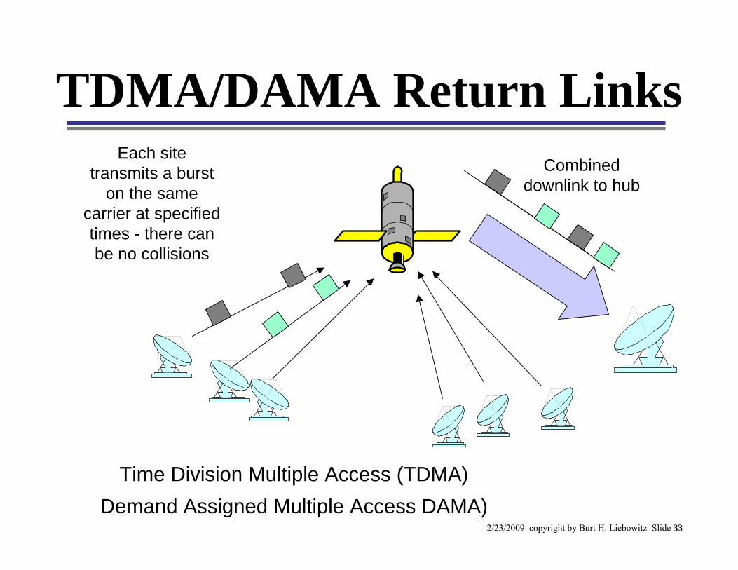
TDMA/DAMA Return LinksEach site
transmits a burst on the same
carrier at specified times - there can be no collisions
Combined downlink to hub
Time Division Multiple Access (TDMA)Demand Assigned Multiple Access DAMA)
2/23/2009 copyright by Burt H. Liebowitz Slide 34
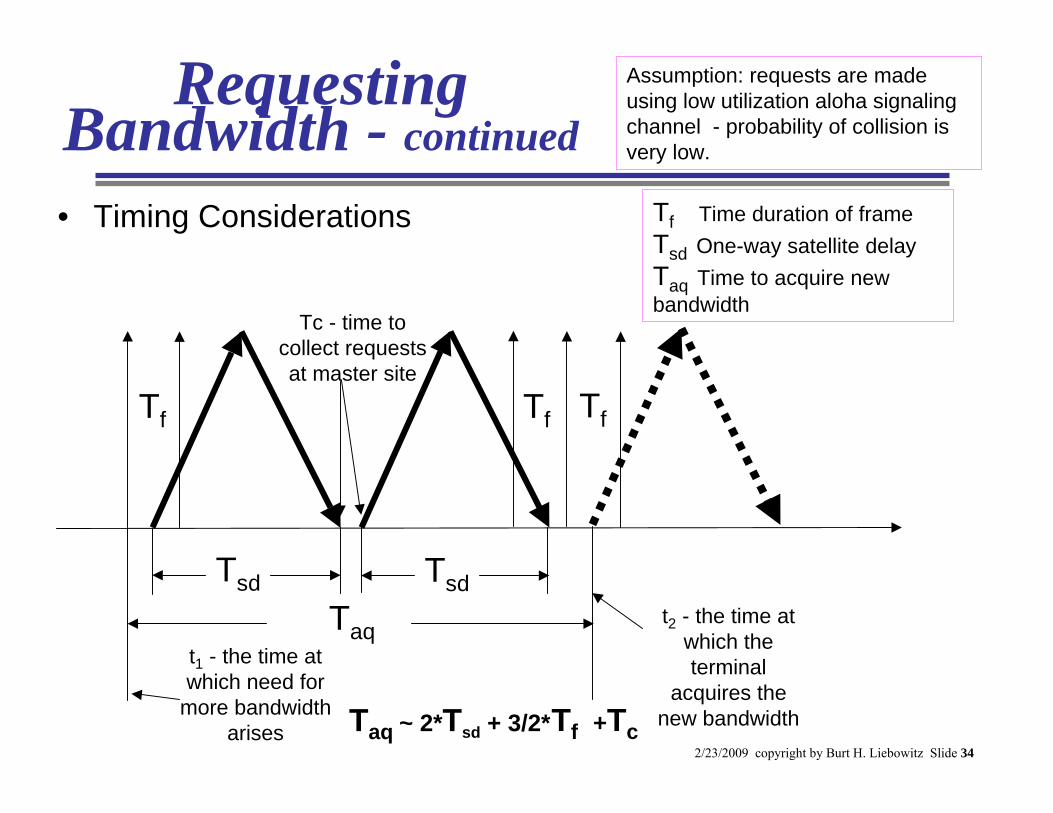
Requesting Bandwidth - continued
• Timing Considerations
Tf Tf
Tsd Tsd
Tf
t1 - the time at which need for
more bandwidth arises
t2 - the time at which the terminal
acquires the new bandwidth
Taq
Tf Time duration of frame Tsd One-way satellite delay Taq Time to acquire new bandwidth
Tc - time to collect requests at master site
TfTaq ~ 2*Tsd + 3/2* +Tc
Assumption: requests are made using low utilization aloha signaling channel - probability of collision is very low.
2/23/2009 copyright by Burt H. Liebowitz Slide 35
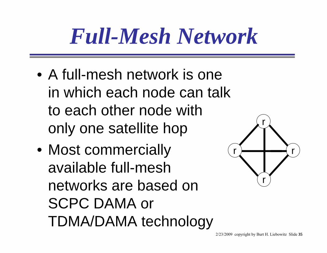
Full-Mesh Network• A full-mesh network is one
in which each node can talk to each other node with only one satellite hop
• Most commercially available full-mesh networks are based on SCPC DAMA or TDMA/DAMA technology
r
r
r
r
2/23/2009 copyright by Burt H. Liebowitz Slide 36
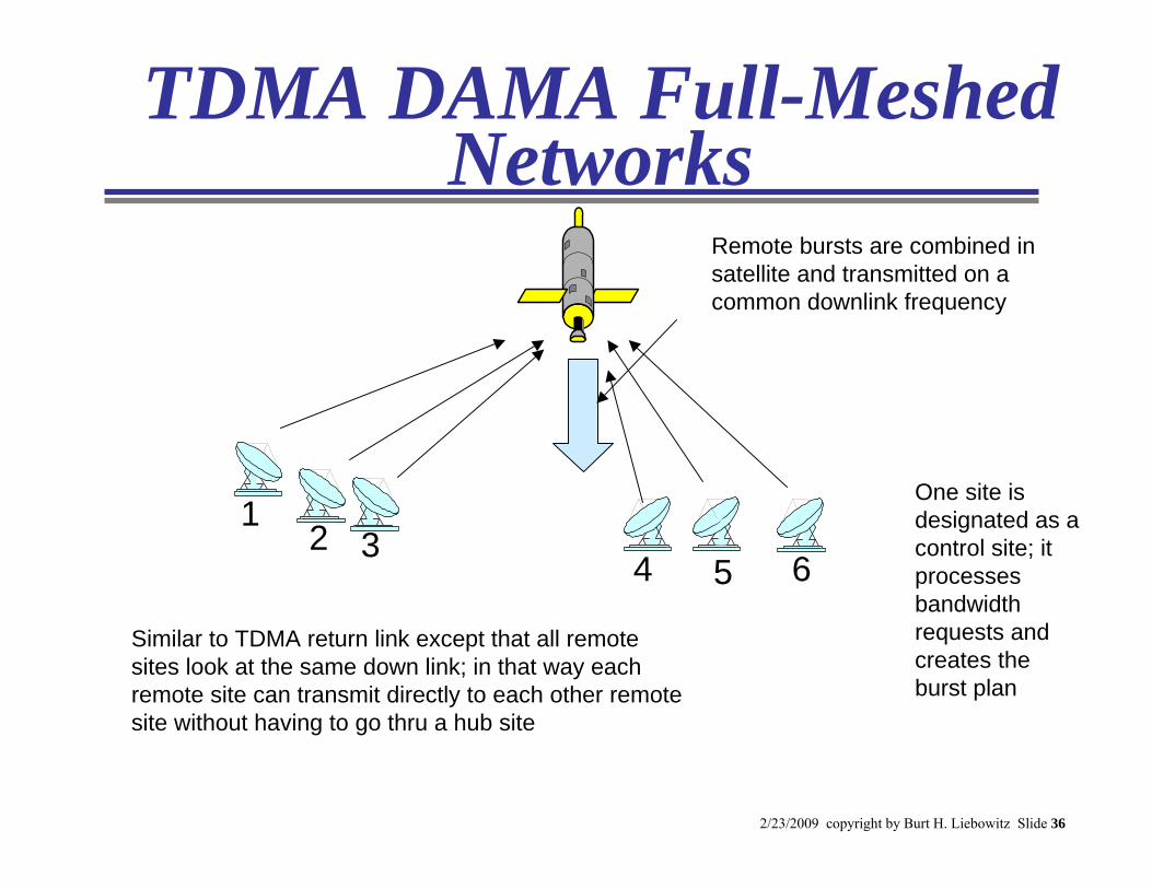
TDMA DAMA Full-Meshed Networks
Similar to TDMA return link except that all remote sites look at the same down link; in that way each remote site can transmit directly to each other remote site without having to go thru a hub site
5
One site is designated as a control site; it processes bandwidth requests and creates the burst plan
12 3
4 6
Remote bursts are combined in satellite and transmitted on a common downlink frequency
2/23/2009 copyright by Burt H. Liebowitz Slide 37
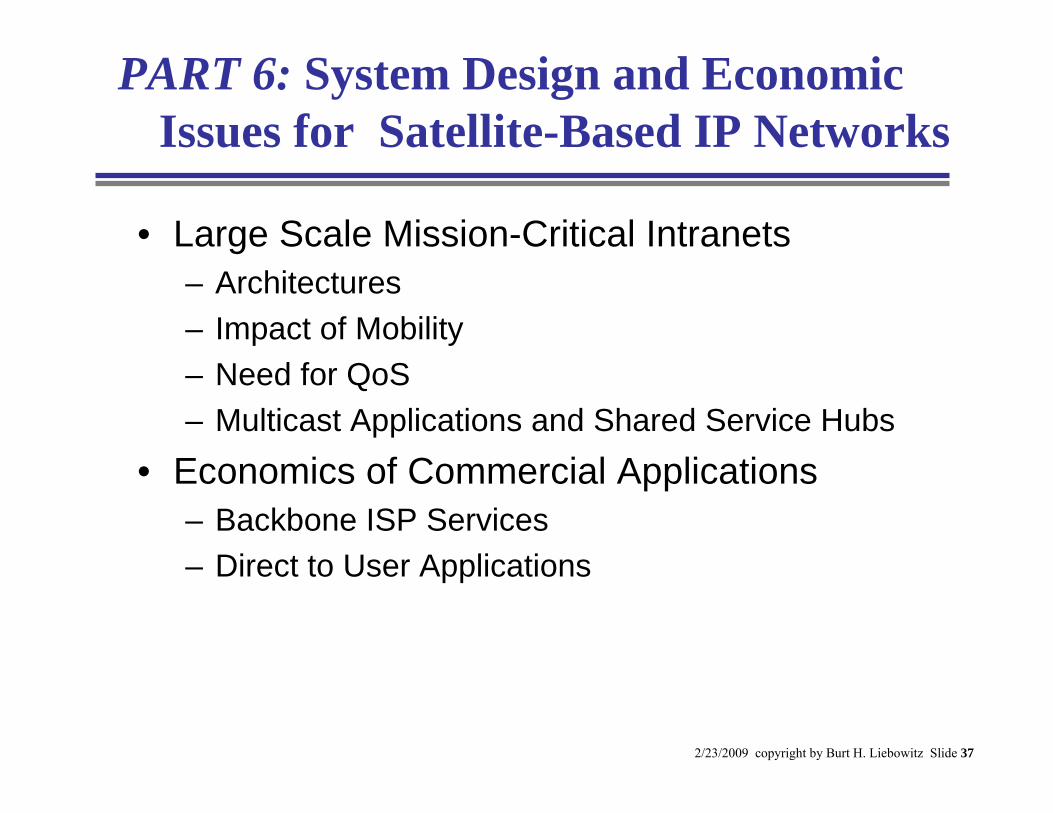
PART 6: System Design and Economic Issues for Satellite-Based IP Networks
• Large Scale Mission-Critical Intranets– Architectures– Impact of Mobility – Need for QoS– Multicast Applications and Shared Service Hubs
• Economics of Commercial Applications– Backbone ISP Services– Direct to User Applications
2/23/2009 copyright by Burt H. Liebowitz Slide 38
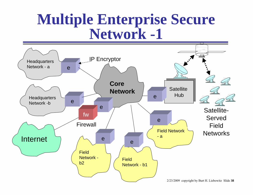
Multiple Enterprise Secure Network -1
Headquarters Network -b
Internet
Headquarters Network - a
Satellite-Served Field
Networks
e
e
Field Network - b1
Field Network -b2
Field Network - a
e
ee
Core Network
Satellite Hub
Satellite Hub
IP Encryptor
Firewall
e
efw
2/23/2009 copyright by Burt H. Liebowitz Slide 39
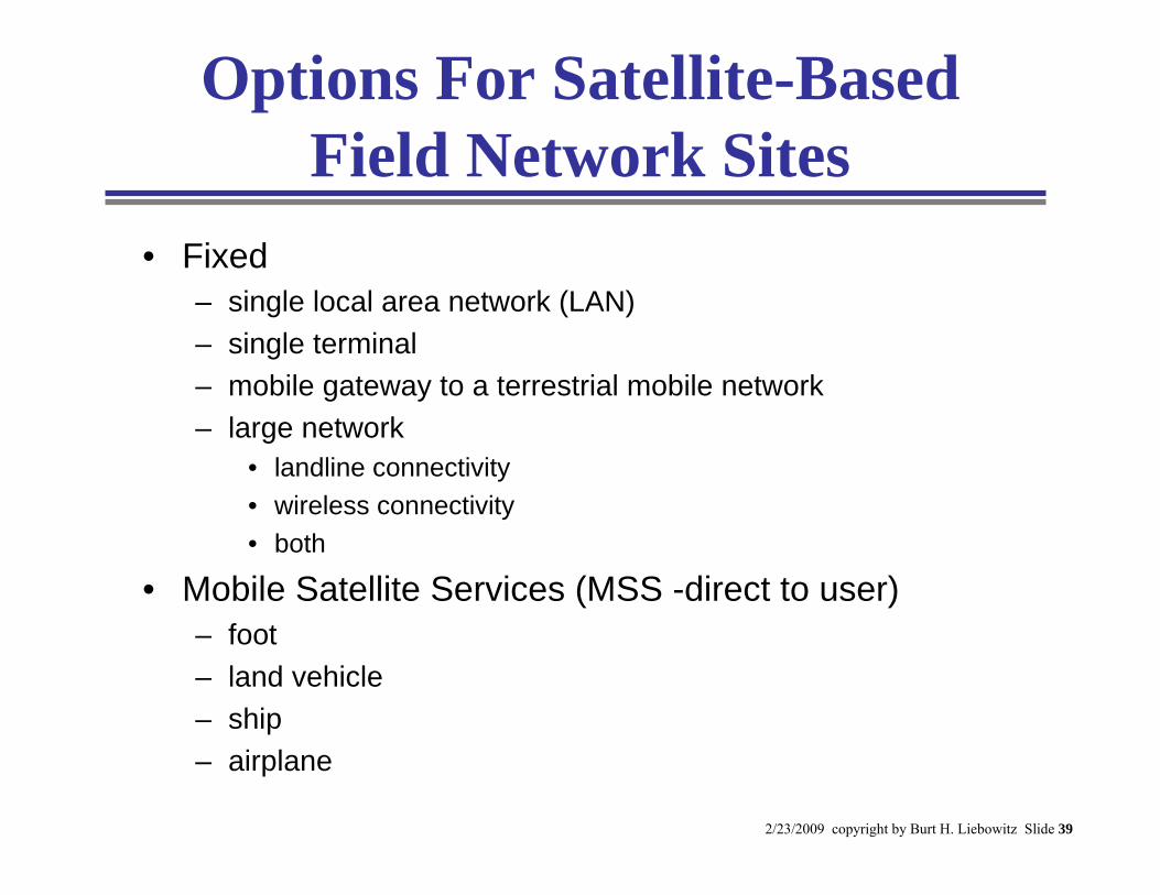
Options For Satellite-Based Field Network Sites
• Fixed– single local area network (LAN)– single terminal– mobile gateway to a terrestrial mobile network– large network
• landline connectivity• wireless connectivity• both
• Mobile Satellite Services (MSS -direct to user)– foot – land vehicle– ship– airplane
2/23/2009 copyright by Burt H. Liebowitz Slide 40
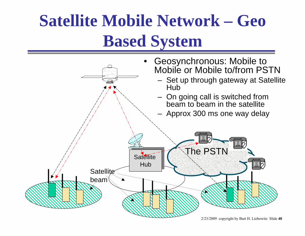
Satellite Mobile Network – Geo Based System
• Geosynchronous: Mobile to Mobile or Mobile to/from PSTN– Set up through gateway at Satellite
Hub– On going call is switched from
beam to beam in the satellite– Approx 300 ms one way delay
Satellite Hub
Satellite Hub
Satellitebeam
The PSTN
2/23/2009 copyright by Burt H. Liebowitz Slide 41
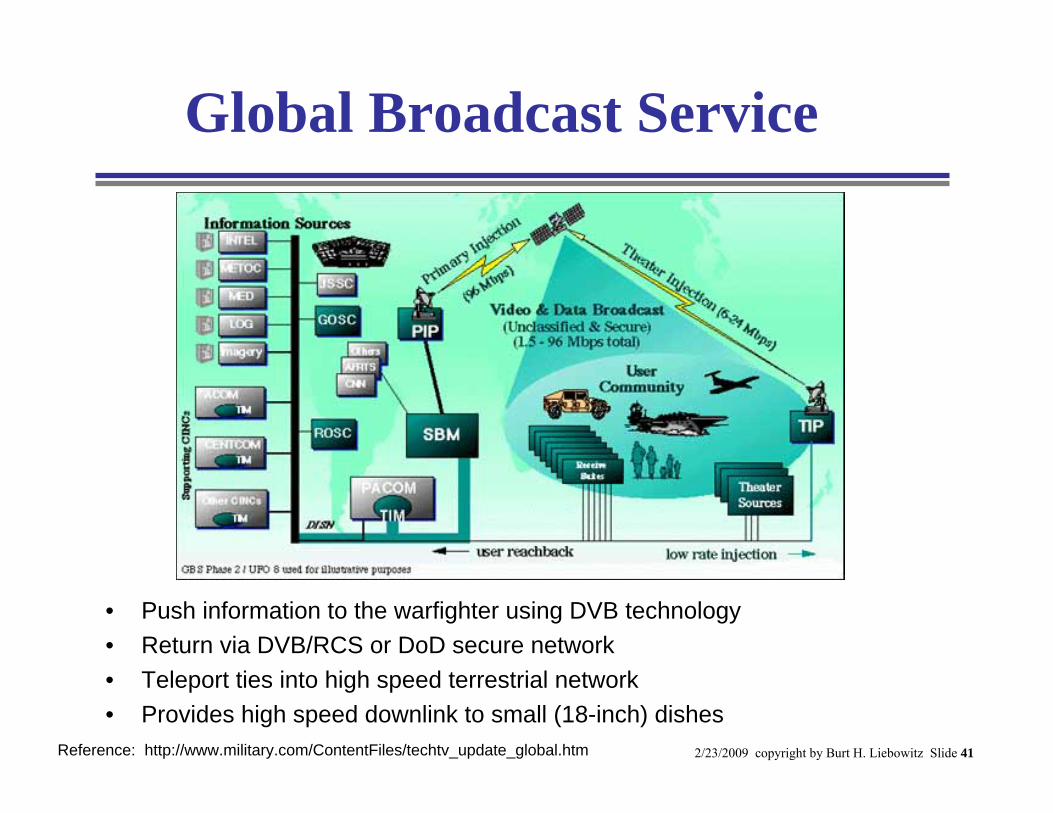
Global Broadcast Service
Reference: http://www.military.com/ContentFiles/techtv_update_global.htm
• Push information to the warfighter using DVB technology• Return via DVB/RCS or DoD secure network• Teleport ties into high speed terrestrial network• Provides high speed downlink to small (18-inch) dishes
2/23/2009 copyright by Burt H. Liebowitz Slide 42
Calculation of Number of Subscribers Per Transponder
• Two types of Subscribers– Browsing Subscriber – 10 Kbytes every 60 seconds– Streaming Subscriber – 128 Kbps
• Streamers represent 40% of total subs• Provision for Overhead – 5% of total channel• Maximum throughput on downstream transponder – 40
Mbps• Question: How many total subscribers can we fit on
transponder and still provide QoS for streams and high effective throughput for browsing subscribers?
• To answer this we need to expand on the concept of effective throughput
2/23/2009 copyright by Burt H. Liebowitz Slide 43
Part 7 - A TDMA/DAMA Design Example
• Enterprise Application–Star network
• Compare Different Architectural Approaches To Determine– Minimum bandwidth approach– Lowest cost approach
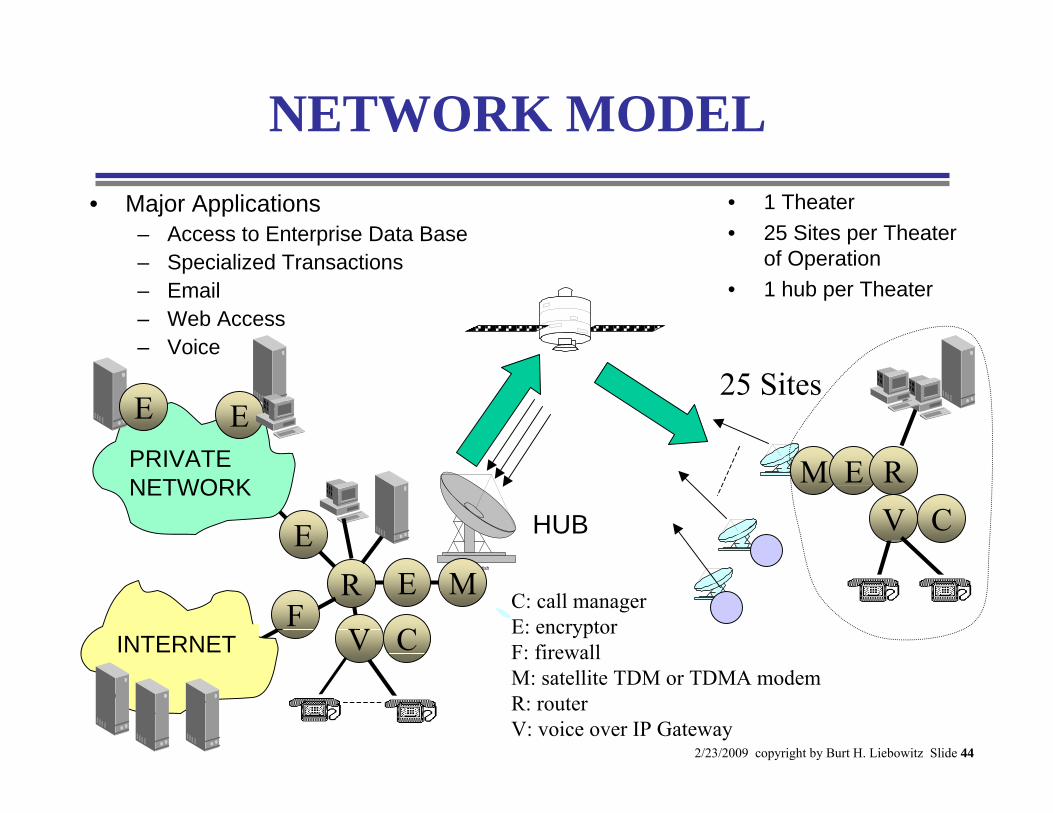
2/23/2009 copyright by Burt H. Liebowitz Slide 44
NETWORK MODEL
Satellite dish
PRIVATE NETWORK
R
HUB
INTERNET
25 Sites
• Major Applications– Access to Enterprise Data Base– Specialized Transactions– Email– Web Access– Voice
• 1 Theater• 25 Sites per Theater
of Operation• 1 hub per Theater
E
C: call managerE: encryptorF: firewallM: satellite TDM or TDMA modemR: routerV: voice over IP Gateway
V
E M
C
M E RV C
F
EE
2/23/2009 copyright by Burt H. Liebowitz Slide 45
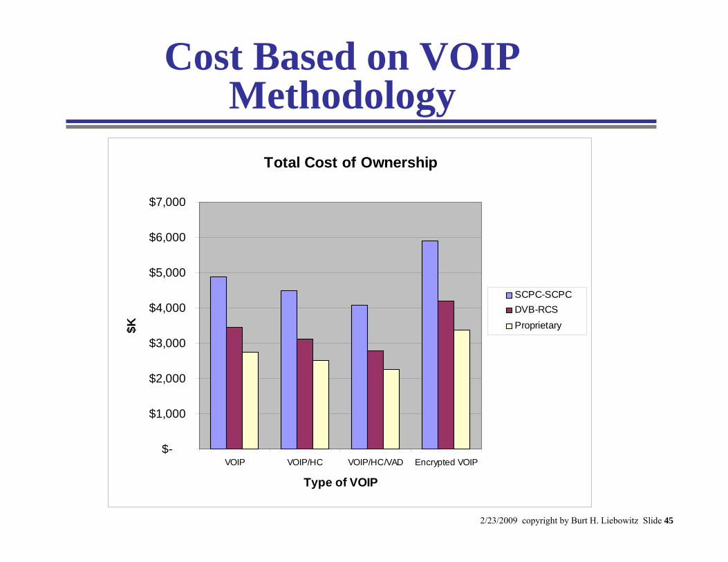
Cost Based on VOIP Methodology
Total Cost of Ownership
$-
$1,000
$2,000
$3,000
$4,000
$5,000
$6,000
$7,000
VOIP VOIP/HC VOIP/HC/VAD Encrypted VOIP
Type of VOIP
$K
SCPC-SCPCDVB-RCSProprietary
2/23/2009 copyright by Burt H. Liebowitz Slide 46
Part 8 – Predicting Performance in Mission-Critical Networks
• Overview and Definitions• A Reference Problem• Introduction to Queuing Theory
– single server– priority queues
• Application of Queuing Theory to Reference Problem
• Use of Simulation
2/23/2009 copyright by Burt H. Liebowitz Slide 47
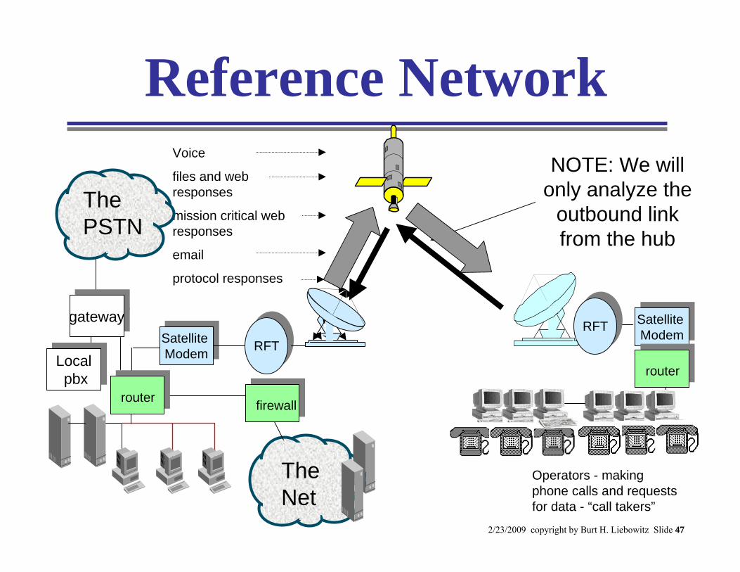
Reference Network
Operators - making phone calls and requests for data - “call takers”
Voice
files and web responses
mission critical web responses
protocol responses
NOTE: We will only analyze the
outbound link from the hub
Satellite Modem
Satellite Modem
RFTRFT
The Net
firewall
The PSTN
gatewaygateway
Localpbx
Localpbx
router
RFTRFTSatellite Modem
Satellite Modem
router
2/23/2009 copyright by Burt H. Liebowitz Slide 48
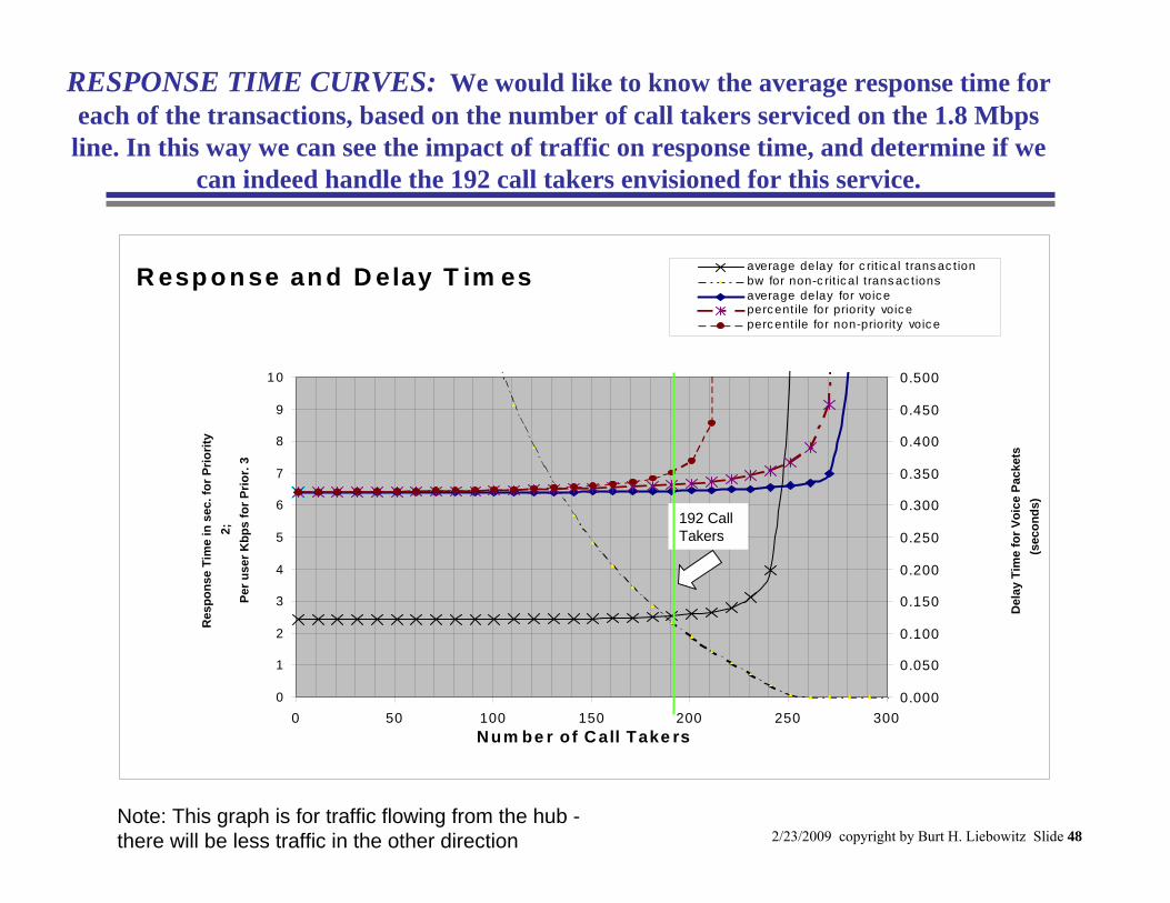
R esp o n se an d D elay T im es
0
1
2
3
4
5
6
7
8
9
10
0 50 100 150 200 250 300N um be r of C all Take rs
Res
pons
e Ti
me
in s
ec. f
or P
riorit
y 2;
Pe
r use
r Kbp
s fo
r Prio
r. 3
0.000
0.050
0.100
0.150
0.200
0.250
0.300
0.350
0.400
0.450
0.500
Del
ay T
ime
for V
oice
Pac
kets
(s
econ
ds)
average delay for c rit ic al trans ac tionbw for non-c rit ic al trans ac tionsaverage delay for voic eperc entile for priority voic eperc entile for non-priority voic e
RESPONSE TIME CURVES: We would like to know the average response time for each of the transactions, based on the number of call takers serviced on the 1.8 Mbps line. In this way we can see the impact of traffic on response time, and determine if we
can indeed handle the 192 call takers envisioned for this service.
Note: This graph is for traffic flowing from the hub -there will be less traffic in the other direction
192 Call Takers
2/23/2009 copyright by Burt H. Liebowitz Slide 49
Part 9 - A View of the Future• Satellite Enhancements
– More power and large antennas– Spot beams and frequency reuse– On board processing– Inter-satellite links– Ka and higher band satellites
• Advanced Satellites– Commercial– Military
• The “Ideal” Earth Station
2/23/2009 copyright by Burt H. Liebowitz Slide 50
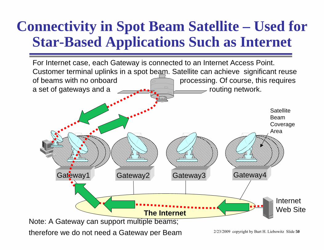
Connectivity in Spot Beam Satellite – Used for Star-Based Applications Such as Internet
Gateway1 Gateway2 Gateway3 Gateway4
For Internet case, each Gateway is connected to an Internet Access Point. Customer terminal uplinks in a spot beam. Satellite can achieve significant reuse of beams with no onboard processing. Of course, this requires a set of gateways and a routing network.
Satellite Beam Coverage Area
Internet Web SiteThe Internet
Note: A Gateway can support multiple beams; therefore we do not need a Gateway per Beam