Embed Size (px)
Citation preview

800.205.7186 • www.codeblue.com
IP5000 2.0 SeriesVoIP Speakerphone
Administrator GuideInstallation, Configuration, Operation & Troubleshooting
Also includes - IP Audio Interface information
Code Blue • 259 Hedcor Street • Holland, MI 49423 USA • 800.205.7186 • www.codeblue.com GU-142-Lpage 2 of 67
IP5000 2.0 SeriesAdministrator Guide
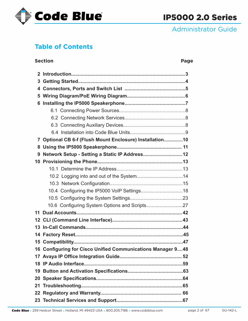
Table of Contents Section Page 2 Introduction.................................................................................... 3 3 Getting Started............................................................................... 4 4 Connectors, Ports and Switch List .............................................5 5 Wiring Diagram/PoE Wiring Diagram........................................... 6 6 Installing the IP5000 Speakerphone............................................. 7 6.1 Connecting Power Sources.................................................8 6.2 Connecting Network Services.............................................8 6.3 Connecting Auxiliary Devices..............................................8 6.4 Installation into Code Blue Units.........................................9 7 Optional CB 6-f (Flush Mount Enclosure) Installation.............. 10 8 Using the IP5000 Speakerphone................................................ 11 9 Network Setup - Setting a Static IP Address............................. 1210 Provisioning the Phone............................................................... 13 10.1 Determine the IP Address.................................................13 10.2 Logging into and out of the System..................................14 10.3NetworkConfiguration......................................................15 10.4ConfiguringtheIP5000VoIPSettings...............................18 10.5ConfiguringtheSystemSettings.......................................23 10.6ConfiguringSystemOptionsandScripts...........................2711 Dual Accounts.............................................................................. 4212 CLI (Command Line Interface).................................................... 4313 In-Call Commands........................................................................ 4414 Factory Reset................................................................................ 4515 Compatibility................................................................................. 4716 Configuring for Cisco Unified Communications Manager 9.... 4817 Avaya IP Office Integration Guide.............................................. 5218 IP Audio Interface......................................................................... 5919 Button and Activation Specifications......................................... 6320 Speaker Specifications................................................................ 6421 Troubleshooting........................................................................... 6522 Regulatory and Warranty............................................................ 6623 Technical Services and Support.................................................67
Code Blue • 259 Hedcor Street • Holland, MI 49423 USA • 800.205.7186 • www.codeblue.com GU-142-Lpage 3 of 67
IP5000 2.0 SeriesAdministrator Guide
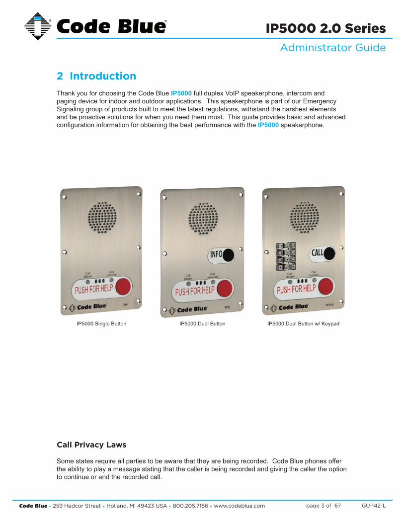
2 IntroductionThank you for choosing the Code Blue IP5000fullduplexVoIPspeakerphone,intercomandpagingdeviceforindoorandoutdoorapplications.ThisspeakerphoneispartofourEmergencySignalinggroupofproductsbuilttomeetthelatestregulations,withstandtheharshestelementsandbeproactivesolutionsforwhenyouneedthemmost.ThisguideprovidesbasicandadvancedconfigurationinformationforobtainingthebestperformancewiththeIP5000speakerphone.
Call Privacy Laws
Somestatesrequireallpartiestobeawarethattheyarebeingrecorded.CodeBluephonesoffertheabilitytoplayamessagestatingthatthecallerisbeingrecordedandgivingthecallertheoptionto continue or end the recorded call.
IP5000DualButtonw/KeypadIP5000SingleButton IP5000DualButton

Code Blue • 259 Hedcor Street • Holland, MI 49423 USA • 800.205.7186 • www.codeblue.com GU-142-Lpage 4 of 67
IP5000 2.0 SeriesAdministrator Guide
3 Getting Started ThischapterprovidesinformationforobtainingthebestperformancewiththeIP5000speakerphone.ItisstronglyrecommendedthattheentireguideisreadbeforeconfiguringyourIP5000speaker-phonetoensureyougetmaximumperformance.
Throughout this guide you will see the following two references:
Calling Party:ThisisthepersonactivatingtheIP5000speakerphonebypressingabutton.
Called Party:ThisisthepersonreceivingthecallfromtheIP5000;typicallyaguard,911operator,dispatchofficer,etc.
TheIP5000speakerphoneprovidespowerful,yetflexibleIPemergencycommunication,deliveringexcellentvoicequalityforyouremergencyspeakerphone,intercomandpagingsolution.
Code Blue • 259 Hedcor Street • Holland, MI 49423 USA • 800.205.7186 • www.codeblue.com GU-142-Lpage 5 of 67
IP5000 2.0 SeriesAdministrator Guide
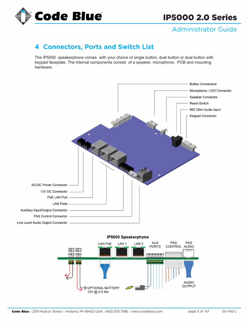
4 Connectors, Ports and Switch ListTheIP5000speakerphonecomeswithyourchoiceofsinglebutton,dualbuttonordualbuttonwithkeypadfaceplate.Theinternalcomponentsconsistofaspeaker,microphone,PCBandmountinghardware.
Code Blue • 259 Hedcor Street • Holland, MI 49423 USA • 800.205.7186 • www.codeblue.com GU-142-Lpage 6 of 67
IP5000 2.0 SeriesAdministrator Guide
5 Wiring Diagram/PoE Wiring Diagram
ED Image page
2
802.3af / at Switch
LAN 2LAN 1WANPoE PAS
ControlAux portsPASAudio+ -+ -
Power | Battery
S-550 S1000
Ethernet
1
IP5000 Connector Side
Grounding:
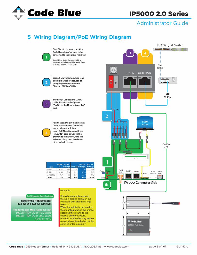
Should a ground be needed,there’s a ground screw on the enclosure with grounding logonext to it.When the splitter is mounted tothe mounting bracket the bracketbecomes the ground to thechassis of the enclosure,however local codes may requirea ground wire be attached to thescrew in order to comply.
43
Data +PoEDATA
1b
LED Faceplate Light Bar
12VDC
PoE
CB14591 PoE Splitter
2.6
2.1
1.3
1
First, Electrical connection: All 3 Code Blue device’s should to be connected to the 5 place manifold
Special Note: Notice the power cable is connected to the Battery / Alternative Power
port of the IP5000. – See Item 1b
2Second: Manifolds fused red lead and black wires are secured to spring cage connector on the CB14591. SEE DIAGRAM
Third Step: Connect the DATA cable RJ-45 from the Splitter “DATA” to the IP5000 WAN PoE port.
3
4
Fourth Step: Plug in the Ethernet PoE Cat 5e Cable to Data+PoE Input jack on the Splitters.Upon PoE Negotiation with the PoE switch port, power will be granted to the Splitter, and the indicator along with the device attached will turn on.
ItemInRush
(i)InRush
Wattage Norm (i)802.3af Wattage
802.3at Wattage
IP5000 0.22 2.64 0.09 1.08 1.08
FP LED 0.08 0.96 0.04 0.48 0.48
Combo LED 0.3 3.6 0.26 3.12 3.12
Totals 0.6 7.20 0.39 4.68 4.68
CAT5e< 3ft
in out GRD
3ftCat5e
CustCat5e

Code Blue • 259 Hedcor Street • Holland, MI 49423 USA • 800.205.7186 • www.codeblue.com GU-142-Lpage 7 of 67
IP5000 2.0 SeriesAdministrator Guide
6 Installing the IP5000 SpeakerphoneTheIP5000speakerphoneiscapableofbeingconnectedtoPoE(802.11af&at),12-24VoltsACorDCpowersources.Additionally,theIP5000mayalsobeconfiguredwitha12-VoltDCbatterybackuporalternative12VDCpowersourcesystemwhichmonitorsandreportslowvoltageconditionforensureduptime.
TheIP5000speakerphonehasthreeEthernetswitchports,onePoELANandtwonon-PoELANSavailableforconnectivitytonetworkservicesandforadditionalnetworkconnectivityforauxiliarydevices,suchasIPcameras,cardreaders,etc.AdditionalLANSarenotVLANcompatible.
TheIP5000speakerphonehastwonormallyopenauxiliaryoutputcontactsforconnectingdevicessuchastheLEDbeacon/strobe,camerapresetactivationinputs,thirdpartycontrollers,etc.Thereisalsoonenormallyopenauxiliaryinputcontactclosureforconnectingdevices,suchasdoorcontacts,relays,etc.,whichcanbeprogrammedtoperformanyfunctionofthephone.
TheIP5000speakerphonehasbeendesignedtobemountedinanyCodeBlueenclosure.Customfaceplatesareavailableformountinginotherproductenclosures.Contactyourlocaldealerforadditionalinformationandavailabilityofcustomoptions.

Code Blue • 259 Hedcor Street • Holland, MI 49423 USA • 800.205.7186 • www.codeblue.com GU-142-Lpage 8 of 67
IP5000 2.0 SeriesAdministrator Guide
6.1 Connecting Power Sources
TheIP5000speakerphoneiscapableofbeingconnectedtoanypowersourcethatprovides12-24VoltsACorDCwithaminimumof430mAcurrentrating.Optionally,a2.0AhrbatterycanbeconnectedtothesecondarypowerinputandtheIP5000speakerphonewillmonitorthebatteryforlowvoltageconditions.WhenusedinsolarorNightCharge®applications,thesystem’sbatteriesvoltagearemonitoredforlowbatterycondition.Itisstronglyrecommendedthatyoudisconnectanypowertotheunitpriortoinstallation.ConsultyourlocalelectricianforproperpowerconnectivitytoyourCodeBlueequipment.
6.2 Connecting Network Services
TheIP5000speakerphonehasthreeEthernetportsthatprovidebothanupstreamnetworkconnectionpoint,aswellasfunctionasanEthernetswitch.UpstreamnetworkconnectivityfortheIP5000canbeconnectedtoanyoftheseports,however,onlytheleftmostportacceptsPoEpower.Additionaldevices,suchasIPcameras,cardreaders,etc.canbeconnectedtotheremainingports.
NotethatiftheIP5000isconfiguredwithaVLANID(seesection10,“VLANConfiguration”),onlythespeakerphoneitselfwillcommunicateusingVLAN-taggedpackets.IfadditionaldevicesconnectedtotheIP5000’sotherEthernetportsmustcommunicateonaVLAN,theymusteithersupportVLANtaggingthemselves(whichwillbepassedthroughtheIP5000’sbuilt-inswitch)ortheupstreamconnectionmustbeprovidinguntaggedpacketsfromthatVLAN.
6.3 Connecting Auxiliary Devices
TheIP5000speakerphone’sanalogauxiliaryconnectionsaretwonormallyopenoutputsandonenormallyopeninput.Typically,anyCodeBlueunitwithanLEDbeacon/strobewillhavethetriggerconnectedtoAuxiliaryOutput1.TheAuxiliaryOutputscanbeprogrammedtobeactiveduringacallorbyenteringaspecifictimeperiod.NewtoVersion2,theauxiliaryoutputcouldbeconfiguredformomentaryon-demandtimedactivationsviaDTMFfromthecalledpartyphone.TheAuxiliaryInputcanbeprogrammedtoperformanyscriptenteredintothephone.SeeIP5000UserGuideforfurtherinformationonprogrammingtheauxiliaryoutputs.
IN-147-C
IP5000 v2.0.0 Administrator’s Guide
259HedcorStreetHolland,MI49423800.205.7186www.codeblue.com
1-4 CONNECTING POWER SOURCES TheIP5000speakerphoneiscapableofbeingconnectedtoanypower sourcethatprovides12-24VoltsACorDCwithaminimumof430mA currentrating.Optionally2.0Ahrbatterycanbeconnectedtothe secondarypowerinputandtheIP5000speakerphonewillmonitorthe batteryforlowvoltageconditions.Whenusedinsolar or NightCharge® applications,thesystembatteriesvoltagearemonitoredforlowbattery condition.Itisstronglyrecommendedthatyoudisconnectanypower totheunitpriortoinstallation.Consultyourlocalelectricianforproper powerconnectivitytoyourCodeBlueequipment. 1.5 Connecting Network Services TheIP5000speakerphonehasthreeEthernetportsthatprovidebothanupstreamnetworkconnectionpointaswell fasfunctionasanEthernetswitch.Upstreamnetworkconnectivityfor theIP5000canbeconnectedtoanyofthese ports;however,onlytheleftmostportacceptsPoEpower.AdditionaldevicessuchasIPcameras,cardreaders,etc. canbeconnectedtotheremainingports. NotethatiftheIP5000isconfiguredwithaVLANID (seesection2.5,"VLANConfiguration"),onlythe speakerphoneitselfwillcommunicateusingVLAN-tagged packets.IfadditionaldevicesconnectedtotheIP5000's otherEthernetportsmustcommunicateonaVLAN,they musteithersupportVLANtaggingthemselves(whichwill bepassedthroughtheIP5000'sbuilt-inswitch),orthe upstreamconnectionmustbeprovidinguntaggedpackets fromthatVLAN. 1-6 CONNECTING AUXILIARY DEVICES TheIP5000speakerphoneanalogauxiliaryconnectionsare two(2)normallyopenoutputsandone(1)normallyopeninput. TypicallyanyCodeBlueunitwithaLEDbeacon/strobewill havethetriggerconnectedtoAuxiliaryOutput1.TheAuxiliary Outputscanbeprogrammedtobeactiveduringacallorby enteringaspecifictimeperiod.Newtoversion2theauxiliary outputcouldbeconfiguredformomentaryon-demand timed activationsviaDTMFfromthecalledpartyphone.The AuxiliaryInputcanbeprogrammedtoperformanyscript enteredintothephone.Seesections5-8,5-10through5-12 forfurtherinformationonprogrammingtheauxiliaryoutputs.
Page 6
12-24VACorDC
OptionalBattery12VDC2Ahr
Ethernet
PoE LAN LAN LAN
Auxiliary Ports
AuxOutput1 AuxOutput2
AuxOutput1

Code Blue • 259 Hedcor Street • Holland, MI 49423 USA • 800.205.7186 • www.codeblue.com GU-142-Lpage 9 of 67
IP5000 2.0 SeriesAdministrator Guide
6.4 Installation into Code Blue Units
TheIP5000speakerphoneisdesignedtofitintoanyexistingornewCodeBlueunitenclosure.ItisadirectreplacementfortheInterActanalogseries:IA2000,IA3000,IA3100,IA4000andIA4100.Additionally,CodeBlueofferscustomfaceplatedesignsthatallowtheIP5000tobeplacedinmanydifferentenclosuretypes.CodeBlueprovidessixcustomsecurityscrewsandsecuritybitswitheachCodeBlueunitforattachingtheIP5000speakerphone.Consultyourunitinstallationinstructions for further information.
IN-147-C
IP5000 v2.0.0 Administrator’s Guide
259HedcorStreetHolland,MI49423800.205.7186www.codeblue.com
1-7 INSTALLATION INTO CODE BLUE UNITS TheIP5000speakerphoneisdesignedtofitintoanyexistingornewCodeBlueunitenclosure.Itisadirect replacementfortheInterActanalogseries:IA2000,IA3000,IA3100,IA4000andIA4100.Additionally,CodeBlue offerscustomfaceplatedesignsallowingtheIP5000tobeplacedinmanydifferentenclosuretypes.CodeBlue providessix(6)custom securityscrewsandsecuritybitwitheachCodeBlueunitforattachingtheIP5000 speakerphone.Consultyourunitinstallationinstructionsforfurtherinformation.
Page7
Code Blue • 259 Hedcor Street • Holland, MI 49423 USA • 800.205.7186 • www.codeblue.com GU-142-Lpage 10 of 67
IP5000 2.0 SeriesAdministrator Guide
PRE-INSTALLATION
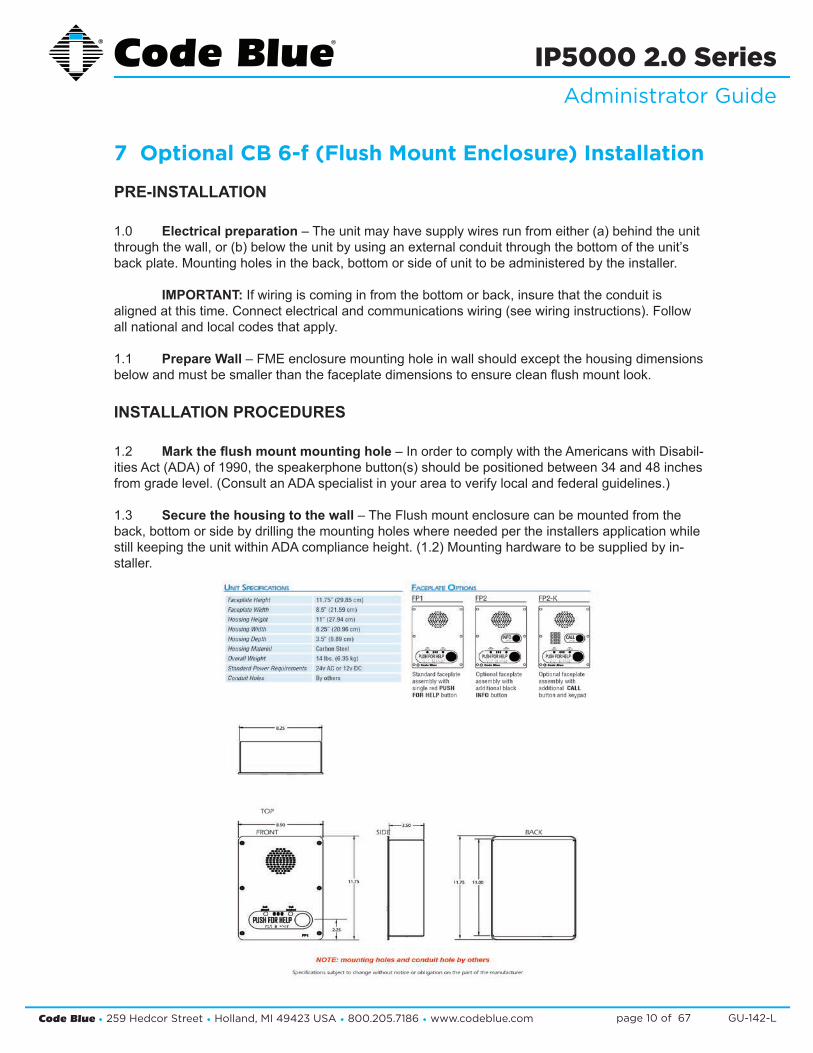
1.0 Electrical preparation–Theunitmayhavesupplywiresrunfromeither(a)behindtheunitthroughthewall,or(b)belowtheunitbyusinganexternalconduitthroughthebottomoftheunit’sbackplate.Mountingholesintheback,bottomorsideofunittobeadministeredbytheinstaller.
IMPORTANT:Ifwiringiscominginfromthebottomorback,insurethattheconduitisalignedatthistime.Connectelectricalandcommunicationswiring(seewiringinstructions).Followallnationalandlocalcodesthatapply.
1.1 Prepare Wall–FMEenclosuremountingholeinwallshouldexceptthehousingdimensionsbelowandmustbesmallerthanthefaceplatedimensionstoensurecleanflushmountlook.
INSTALLATION PROCEDURES
1.2 Mark the flush mount mounting hole–InordertocomplywiththeAmericanswithDisabil-itiesAct(ADA)of1990,thespeakerphonebutton(s)shouldbepositionedbetween34and48inchesfromgradelevel.(ConsultanADAspecialistinyourareatoverifylocalandfederalguidelines.)
1.3 Secure the housing to the wall–TheFlushmountenclosurecanbemountedfromtheback,bottomorsidebydrillingthemountingholeswhereneededpertheinstallersapplicationwhilestillkeepingtheunitwithinADAcomplianceheight.(1.2)Mountinghardwaretobesuppliedbyin-staller.
7 Optional CB 6-f (Flush Mount Enclosure) Installation

Code Blue • 259 Hedcor Street • Holland, MI 49423 USA • 800.205.7186 • www.codeblue.com GU-142-Lpage 11 of 67
IP5000 2.0 SeriesAdministrator Guide
8 Using the IP5000 Speakerphone TheIP5000speakerphonecanbeconfiguredformultipleuses.Themainfunctionistoprovidetwo-wayvoicecommunications.Pressingbutton#1(Redbutton)PUSH FOR HELP, EMERGENCY or EMERGENCY/EMERGENCIAwillactivatetheconfiguredscriptprogrammedforbutton#1.
Button#1activationoverridesanyotheractiontheIP5000isperformingatthetimeofthebuttonpress.Forexample,iftheIP5000was:
1. Beingprogrammedatthetime2. In a monitoring call3. In the middle of a diagnostic test4. IntheprocessofaPublicAlertsession5. Inaninformation(button#2)call.
Button#2,INFO or CALL,aretypicallyutilizedforplacinginformationalcallsorforacquiringdialtoneandutilizingthekeypad,respectively.Anyactionotherthanbutton#1activationisconsideredNon-Prioritycallingandcommonlyutilizedfordirectorservice,student/employeeparkinglotescortrequests,gateentryrequests,guestservicesandsimilarrequests.
TheIP5000speakerphone’sAuxiliaryOutputsaretypicallyutilizedforactivatingCodeBlue’sLEDBeacon/Strobe,andcanbeusedasanormallyopen(N.O.)drycontactclosure(seeA&Especforrelayratings)used,forexample,toactivatecentralizedbuilding/securitymanagementequipment.
TheIP5000speakerphone’sAuxiliaryInputisutilizedtomakeanemergencycallorotherfunctionwhenactivated.Itcanbeconnectedtoanynormallyopen(N.O.)outputcontactandwillinitializetheconfiguredscriptwhenactivated.Typicaluseswouldbedoororgatecontactsforunauthorizedentry,motionsensoractivations,andactivationuponremovalofLifeRingsonpiersorbeaches.TheauxiliaryInputcanbeusedtoresetanoutputleftenabledforlocationidentificationafteracallhasbeenterminatedbythesecuritydesk.
AuxiliaryInputrequiresavoltageof9-32voltsACorDCtodetectaremotedevicescontactclosure.
Incomingcalls:TheIP5000auto-answersanincomingcall,BasedonthesettingsconfiguredinGeneral Configuration > Incoming Calls > Answer inImmediatelyorafteranumberofrings.IftheIP5000Public Address > Always Route Incoming Calls to Public Addresswasenabled,allansweredcallswillnowbebroadcasttothePublicAddressSystem.Inordertocounterthatautomaticanswer/publicaddressenablefeature,thecaller(guard)canexitoutofthatmodeusingthe#2keyonhiskeypad.
Code Blue • 259 Hedcor Street • Holland, MI 49423 USA • 800.205.7186 • www.codeblue.com GU-142-Lpage 12 of 67
IP5000 2.0 SeriesAdministrator Guide
9 Network Setup
Determine the IP Address
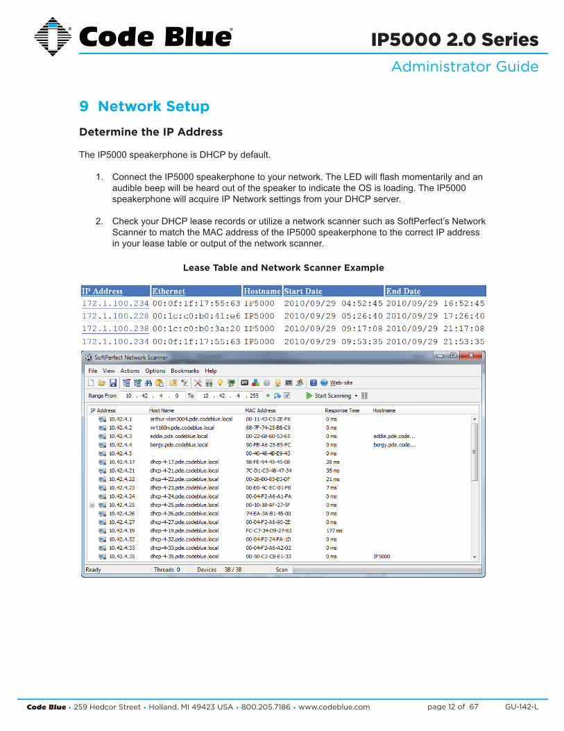
TheIP5000speakerphoneisDHCPbydefault.
1. ConnecttheIP5000speakerphonetoyournetwork.TheLEDwillflashmomentarilyandan audiblebeepwillbeheardoutofthespeakertoindicatetheOSisloading.TheIP5000 speakerphonewillacquireIPNetworksettingsfromyourDHCPserver.
2. CheckyourDHCPleaserecordsorutilizeanetworkscannersuchasSoftPerfect’sNetwork ScannertomatchtheMACaddressoftheIP5000speakerphonetothecorrectIPaddress inyourleasetableoroutputofthenetworkscanner.
Lease Table and Network Scanner Example
Code Blue • 259 Hedcor Street • Holland, MI 49423 USA • 800.205.7186 • www.codeblue.com GU-142-Lpage 13 of 67
IP5000 2.0 SeriesAdministrator Guide
10 Provisioning the Phone
10.1 Setting a Static IP Address
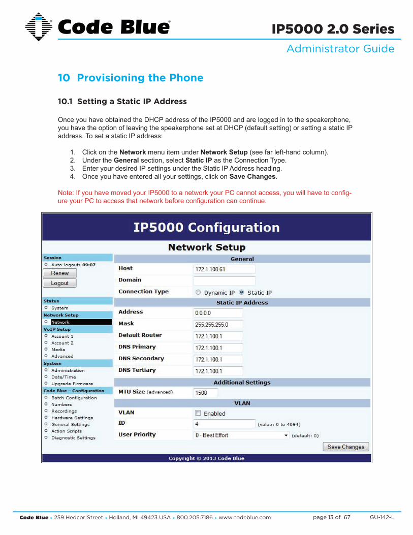
OnceyouhaveobtainedtheDHCPaddressoftheIP5000andareloggedintothespeakerphone,youhavetheoptionofleavingthespeakerphonesetatDHCP(defaultsetting)orsettingastaticIPaddress. To set a static IP address:
1. Click on the Network menu item under Network Setup(seefarleft-handcolumn).2. Under the Generalsection,selectStatic IPastheConnectionType.3. EnteryourdesiredIPsettingsundertheStaticIPAddressheading.4. Onceyouhaveenteredallyoursettings,clickonSave Changes.
Note:IfyouhavemovedyourIP5000toanetworkyourPCcannotaccess,youwillhavetoconfig-ureyourPCtoaccessthatnetworkbeforeconfigurationcancontinue.

Code Blue • 259 Hedcor Street • Holland, MI 49423 USA • 800.205.7186 • www.codeblue.com GU-142-Lpage 14 of 67
IP5000 2.0 SeriesAdministrator Guide
10.2 Logging into and out of the System
Logging into the System
1. Loginusingawebbrowser.
A. PlacetheIPAddressofyourIP5000intotheURLaddressbarandpressENTER.
B. Dependingonthebrowserbeingused,acertificatewarningmaypopup.Goahead andapproveinordertoloadthelogindialogbox.
C. Enterusername“admin”andpassword“admin”andpressENTER.
2. System Status Screen.
A. CurrentsessiontimebeforeAuto-Logoutisexecuted.
B. Clicking Renewwillrestartthetimerto10minutes,effectivelykeepingyoulogged in.Thisstatehelpspreventothersfromlogginginandtakingoverthesession, therefore erasing any unsaved changes made.
C. Clicking Logout will log you out of the GUI.
D. Network:DisplayscurrentIPaddress,DNSaddress,DNSTertiaryaddress,Account 1’scurrentstatusandAccount2’scurrentstatus.

Code Blue • 259 Hedcor Street • Holland, MI 49423 USA • 800.205.7186 • www.codeblue.com GU-142-Lpage 15 of 67
IP5000 2.0 SeriesAdministrator Guide
Logging into the System
1. TologoutoftheIP5000speakerphone,simplyclickonLogout under Session (seefarleft- handcolumn). Thespeakerphonewillalsologyououtautomaticallyafter10minutes. Youwillbepromptedforconfirmation.
2. Click OKtocompletethelogoutprocessorCanceltocontinueconfiguringyourIP5000.
Code Blue • 259 Hedcor Street • Holland, MI 49423 USA • 800.205.7186 • www.codeblue.com GU-142-Lpage 16 of 67
IP5000 2.0 SeriesAdministrator Guide
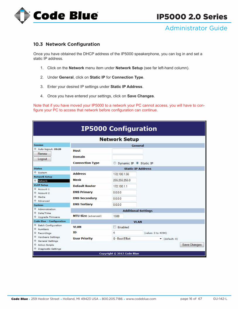
10.3 Network Configuration
OnceyouhaveobtainedtheDHCPaddressoftheIP5000speakerphone,youcanloginandsetastatic IP address.
1. Click on the Network menu item under Network Setup(seefarleft-handcolumn).
2. Under General,clickonStatic IP for Connection Type.
3. EnteryourdesiredIPsettingsunderStatic IP Address.
4. Onceyouhaveenteredyoursettings,clickonSave Changes.
NotethatifyouhavemovedyourIP5000toanetworkyourPCcannotaccess,youwillhavetocon-figureyourPCtoaccessthatnetworkbeforeconfigurationcancontinue.
Code Blue • 259 Hedcor Street • Holland, MI 49423 USA • 800.205.7186 • www.codeblue.com GU-142-Lpage 17 of 67
IP5000 2.0 SeriesAdministrator Guide
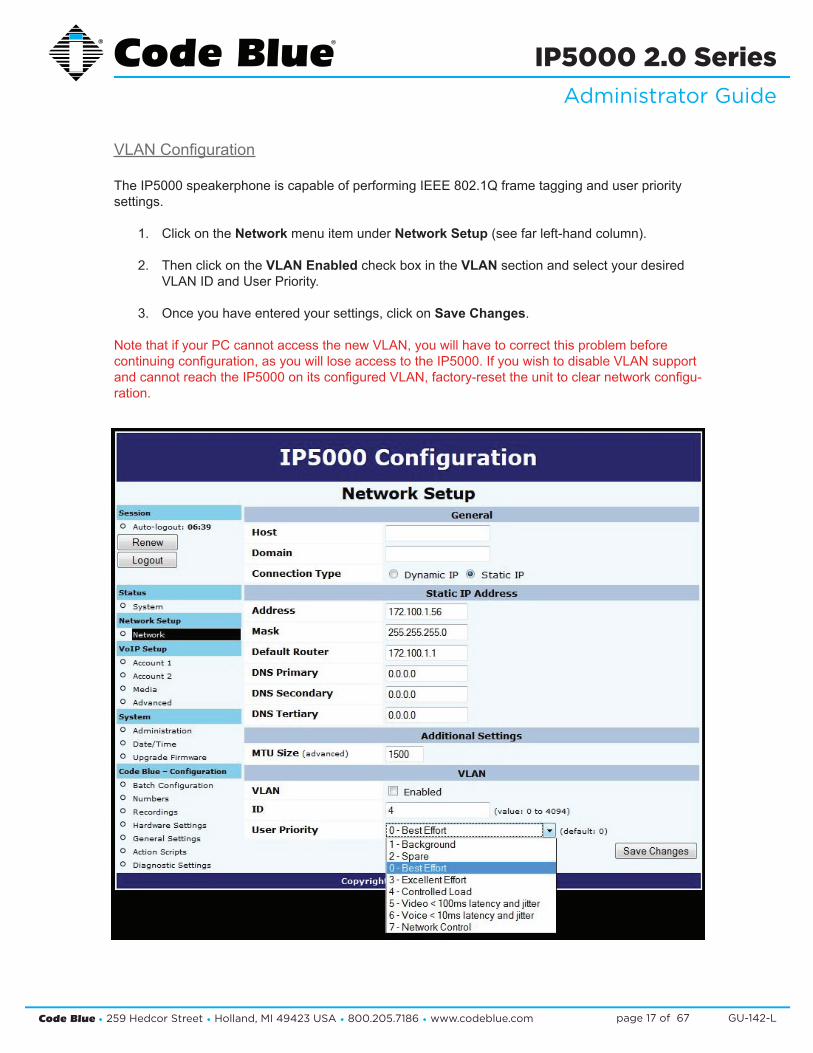
VLANConfiguration
TheIP5000speakerphoneiscapableofperformingIEEE802.1Qframetagginganduserprioritysettings.
1. Click on the Network menu item under Network Setup(seefarleft-handcolumn).
2. Then click on the VLAN EnabledcheckboxintheVLAN section and select your desired VLANIDandUserPriority.
3. Onceyouhaveenteredyoursettings,clickon Save Changes.
NotethatifyourPCcannotaccessthenewVLAN,youwillhavetocorrectthisproblembeforecontinuingconfiguration,asyouwillloseaccesstotheIP5000.IfyouwishtodisableVLANsupportandcannotreachtheIP5000onitsconfiguredVLAN,factory-resettheunittoclearnetworkconfigu-ration.
Code Blue • 259 Hedcor Street • Holland, MI 49423 USA • 800.205.7186 • www.codeblue.com GU-142-Lpage 18 of 67
IP5000 2.0 SeriesAdministrator Guide
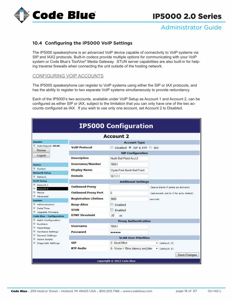
10.4 Configuring the IP5000 VoIP Settings
TheIP5000speakerphoneisanadvancedVoIPdevicecapableofconnectivitytoVoIPsystemsviaSIPandIAX2protocols.Built-incodecsprovidemultipleoptionsforcommunicatingwithyourVoIPsystemorCodeBlue’sToolVox®MediaGateway.STUNservercapabilitiesarealsobuilt-inforhelp-ingtraversefirewallswhenconnectingtheunitoutsideofthehostingnetwork.
CONFIGURINGVOIPACCOUNTS
TheIP5000speakerphonecanregistertoVoIPsystemsusingeithertheSIPorIAXprotocols,andhastheabilitytoregistertotwoseparateVoIPsystemssimultaneouslytoprovideredundancy.
EachoftheIP5000’stwoaccounts,availableunderVoIPSetupasAccount1andAccount2,canbeconfiguredaseitherSIPorIAX,subjecttothelimitationthatyoucanonlyhaveoneofthetwoac-countsconfiguredasIAX.Ifyouwishtouseonlyoneaccount,setAccount2toDisabled.

Code Blue • 259 Hedcor Street • Holland, MI 49423 USA • 800.205.7186 • www.codeblue.com GU-142-Lpage 19 of 67
IP5000 2.0 SeriesAdministrator Guide
ConfiguringaSIPAccount
EitheroftheIP5000speakerphone’stwoaccountscanbeconfiguredtoregistertoaVoIPsystemviaSIP.Configurationisasfollows:
• SettheVoIPProtocoltoSIPandRTP.
• ForDescription,enteranametheIP5000willuseinternallytorefertothisaccount.
• ForUsername/Number,enterthenumberthattheIP5000willuseforSIPaddressing.ThiswilloftenbetheextensionnumberinaVoIP-basedPBX.
• ForDisplayName,enterthenametheIP5000willsendinSIPtransactions.Thiswilloftenbethe calling name of the extension.
• ForDomain,enterthedomaintheIP5000willregisterto.
• ForOutboundProxy,enteraSIPproxytheIP5000shouldsendoutboundcallsto.Ifthisisthesameasthedomain,youcanleavethisfieldblank.
• ForOutboundProxyPort,enteranIPportnumbertheIP5000willsendoutboundcallsto.Typi-cally,thisshouldbeleftat0.
• ForRegistrationLifetime,enterthetimeinsecondstheIP5000willrequestthatitsregistrationbevalidfor.TheIP5000willautomaticallyre-registerbeforethistimeperiodexpires.
• CheckKeep-AliveifyouwanttheIP5000toperiodicallysendOPTIONSrequeststotheSIPserver,e.g.tokeepaNATconnectionalive.
• CheckSTUNifyouwanttoenableSTUNsupportforthisaccount.
• YoucanadjusttheDTMFThreshholdvalueifyouhavedifficultieswiththeIP5000activatingin-callcommandswhennoDTMFispresent.
• ForUsernameandPassword,settheusernameandpass-wordtheIP5000willusetoauthenticate to the domain and outboundproxy.Notethattheusername is used for authenti-cation only and need not match theUsername/NumberfieldiftheVoIPsystemdoesnotexpectitto.
• VLANuserprioritiescanbead-justedforSIPandRTPaudio.
Code Blue • 259 Hedcor Street • Holland, MI 49423 USA • 800.205.7186 • www.codeblue.com GU-142-Lpage 20 of 67
IP5000 2.0 SeriesAdministrator Guide
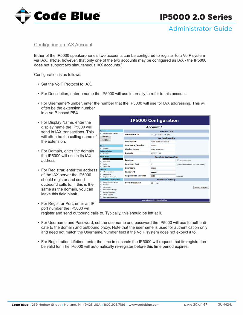
ConfiguringanIAXAccount
EitheroftheIP5000speakerphone’stwoaccountscanbeconfiguredtoregistertoaVoIPsystemviaIAX.(Note,however,thatonlyoneofthetwoaccountsmaybeconfiguredasIAX-theIP5000doesnotsupporttwosimultaneousIAXaccounts.)
Configurationisasfollows:
• SettheVoIPProtocoltoIAX.
• ForDescription,enteranametheIP5000willuseinternallytorefertothisaccount.
• ForUsername/Number,enterthenumberthattheIP5000willuseforIAXaddressing.ThiswilloftenbetheextensionnumberinaVoIP-basedPBX.
• ForDisplayName,enterthedisplaynametheIP5000willsend in IAX transactions. This willoftenbethecallingnameofthe extension.
• ForDomain,enterthedomaintheIP5000willuseinitsIAXaddress.
• ForRegistrar,entertheaddressoftheIAXservertheIP5000should register and send outboundcallsto.Ifthisisthesameasthedomain,youcanleavethisfieldblank.
• ForRegistrarPort,enteranIPportnumbertheIP5000willregisterandsendoutboundcallsto.Typically,thisshouldbeleftat0.
• ForUsernameandPassword,settheusernameandpasswordtheIP5000willusetoauthenti-catetothedomainandoutboundproxy.NotethattheusernameisusedforauthenticationonlyandneednotmatchtheUsername/NumberfieldiftheVoIPsystemdoesnotexpectitto.
• ForRegistrationLifetime,enterthetimeinsecondstheIP5000willrequestthatitsregistrationbevalidfor.TheIP5000willautomaticallyre-registerbeforethistimeperiodexpires.

Code Blue • 259 Hedcor Street • Holland, MI 49423 USA • 800.205.7186 • www.codeblue.com GU-142-Lpage 21 of 67
IP5000 2.0 SeriesAdministrator Guide
ConfiguringMediaSettings
FortheSIPprotocol,youcanspecifyaportrangefromwhichtheIP5000willselectIPportstoofferto the other system for use with RTP communication.
TheIP5000speakerphonecanuseanyoneofasuiteofcodecsforvoicecommunication.Whichco-decisusedisdependentonnegotiationwiththeremotesystem,butyoucanuseCodecSelectiontospecifyalistofpreferredcodecsthatwillbeofferedinnegotiation.
• ToaddcodecstothePreferredlist,highlightthemintheAvailablelistandclickAdd.
• ToremovecodecsfromthePreferredlist,highlightthemandclickRemove.
• Tochangetheorderpreferredcodecsareoffered,highlightthemandclickeitherMoveUporMoveDowntoreorganizethem.
NotethatsomecodecscorruptDTMFtones,e.g.G.729.IfRFC2833out-of-bandDTMFsignalingisnotinuse,besuretoconfigureyourcodecsappropriatelyoryoumaynotbeabletousein-callcom-mands.Besuretotestyourconfigurationtomakesureallfeaturesareavailable.
Code Blue • 259 Hedcor Street • Holland, MI 49423 USA • 800.205.7186 • www.codeblue.com GU-142-Lpage 22 of 67
IP5000 2.0 SeriesAdministrator Guide
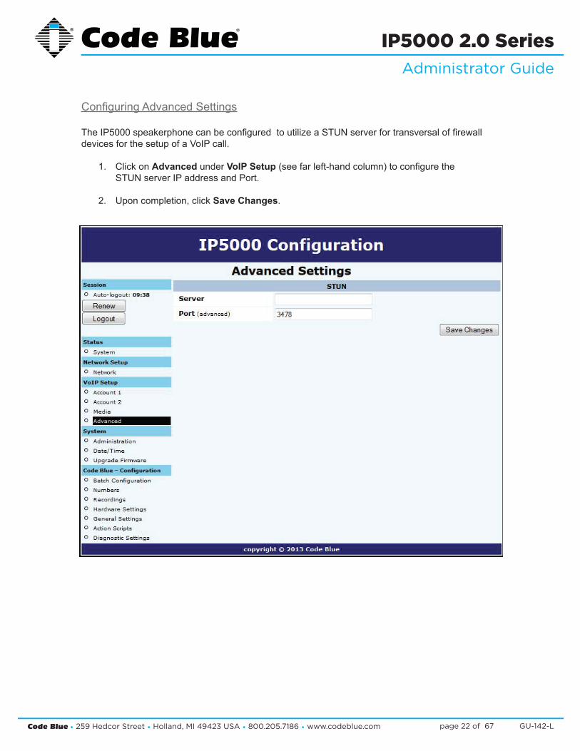
ConfiguringAdvancedSettings
TheIP5000speakerphonecanbeconfiguredtoutilizeaSTUNserverfortransversaloffirewalldevicesforthesetupofaVoIPcall.
1. Click on Advanced under VoIP Setup(seefarleft-handcolumn)toconfigurethe STUN server IP address and Port.
2. Uponcompletion,clickSave Changes.
Code Blue • 259 Hedcor Street • Holland, MI 49423 USA • 800.205.7186 • www.codeblue.com GU-142-Lpage 23 of 67
IP5000 2.0 SeriesAdministrator Guide
10.5 Configuring the System Settings
IP5000speakerphonesystemadministrationisprovidedundertheSystemSettingsdialog,whichallows you to change the following:
• Administrative Logon Credentials
• Syslog Service Reporting
• Secure HTTP Server
• Date and Time
• Upgrade Firmware

Code Blue • 259 Hedcor Street • Holland, MI 49423 USA • 800.205.7186 • www.codeblue.com GU-142-Lpage 24 of 67
IP5000 2.0 SeriesAdministrator Guide
System Administration Settings
TheAdministrationpageunderSystemcontainsseveralsettings:
• System InfodisplaystheMACaddressandfirmwareversionrunningontheIP5000.
• Administrator allowstheadministratorusernameandpasswordtobechanged.Enteranew Username,ifdesired,andenterthenewPassword and again in the Confirmboxtochangetheseparameters.
• TheIP5000cansendRFC5424SyslogmessagestoaSyslogserverbyspecifyingitinthissection. NotethatSyslogmessagesareonlyusefulforadvancedtroubleshootingandarenotintendedfor general monitoring.
• AnewprivatekeyandcertificatecanbeuploadedtotheIP5000’sSecure HTTP Server if you donotwishtousethesystem’sbuilt-inkeyandcertificate.ThekeyshouldbePKCS#8,DER-formattedandthecertificateX.509,DER-formatted.
Whenyouarefinished,clickSaveChanges.YoucanalsorebootthedevicedirectlyfromthispagebyclickingReboot Now.

Code Blue • 259 Hedcor Street • Holland, MI 49423 USA • 800.205.7186 • www.codeblue.com GU-142-Lpage 25 of 67
IP5000 2.0 SeriesAdministrator Guide
DateandTimeConfiguration
TheIP5000speakerphonedateandtimearemanagedby:
1. Clicking Date/Time under System(seefarleft-handcolumn). Under Set Date & Time,youcanmanuallysettheDate,Time,DaylightSavings (ifapplicable)andTimeZone.
2. ToautomaticallysynchronizewithanNTP(NetworkTimeProtocol)server,checkEnabled andentertheIPorURLoftheNTPserver(i.e.Server Address).
3. Click Save Changes.
Code Blue • 259 Hedcor Street • Holland, MI 49423 USA • 800.205.7186 • www.codeblue.com GU-142-Lpage 26 of 67
IP5000 2.0 SeriesAdministrator Guide
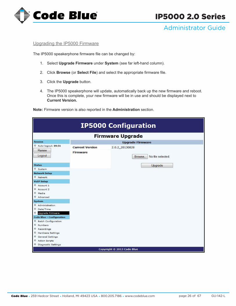
UpgradingtheIP5000Firmware
TheIP5000speakerphonefirmwarefilecanbechangedby:
1. Select Upgrade Firmware under System(seefarleft-handcolumn).
2. Click Browse(orSelect File)andselecttheappropriatefirmwarefile.
3. Click the Upgradebutton.
4. TheIP5000speakerphonewillupdate,automaticallybackupthenewfirmwareandreboot. Oncethisiscomplete,yournewfirmwarewillbeinuseandshouldbedisplayednextto Current Version.
Note: Firmwareversionisalsoreportedinthe Administration section.

Code Blue • 259 Hedcor Street • Holland, MI 49423 USA • 800.205.7186 • www.codeblue.com GU-142-Lpage 27 of 67
IP5000 2.0 SeriesAdministrator Guide
10.6 Configuring System Options and ScriptsTheIP5000speakerphonehasadvancedconfigurationsettingsthatallowforcompletecontrolofthehardwareandhowthesystemperforms.Amemorycapacityof3MBprovidesmultiplephonenumbersandrecordedmessagecapabilities.Incomingcallrouting,SNMPandadvanceddiagnos-ticsenhancedwithadvancedscriptingcapabilitiesprovideforflexibleconfigurations.
BatchConfiguration
TheIP5000speakerphonecanbeconfiguredfromaTFTPserver,e.g.UPD.
1. Click on Batch Configuration under Code Blue(seefarleft-handcolumn)
2. EntertheTFTP Server IP address and TFTP Server Port.
3. Click on Fetch ConfigurationtopulltheconfigurationfilesfromyourTFTPserver.
4. Click on Verify Integritytovalidatetheconfigurationfilesaresuitableforuse.
ThisfunctionalitycanbeusedinlieuofUPD’sprogramfunctionalitytohavetheIP5000pullitscon-figurationinsteadofhavingitpushedfromUPD.

Code Blue • 259 Hedcor Street • Holland, MI 49423 USA • 800.205.7186 • www.codeblue.com GU-142-Lpage 28 of 67
IP5000 2.0 SeriesAdministrator Guide
EnteringPhoneNumbers
TheIP5000speakerphonenumberconfigurationismadeby:
1. Clicking Numbers under Code Blue(seefarleft-handcolumn).
2. Entertheextension(i.e.SIPaccount,userextension).Choosewhichaccountthis extensionnumberwillberelatedto,thenenteradescriptionforthisextension.Seeaccount referenceonpage11.
3. Select the green plus signtoaddthenumber.
4. Todeleteanumbersimplyclickthe red X.
5. Select the green check markwhenprompted, Are you sure?

Code Blue • 259 Hedcor Street • Holland, MI 49423 USA • 800.205.7186 • www.codeblue.com GU-142-Lpage 29 of 67
IP5000 2.0 SeriesAdministrator Guide
Recording Administration
TheIP5000speakerphonerecordingconfigurationismadeby:
1. Selecting Recordings under Code Blue(seefarleft-handcolumn).
2. Click on Select recording file,choosethefileyouwishtouploadtotheIP5000andclick Open.
3. EntertheDescriptionwithintheDescription Field.
4. Click on the green plus signtoaddtherecordingandwaitforittofinish. Duringtheuploadprocessthescreenwilldisplay,Uploading file… Atthispointdonotrefreshthepageorclickawayfromthepageorthefilewillnotbe uploaded.Oncethefileuploadiscomplete,youwillseeDownload Recording and a new lineforuploadingadditionalrecordings.
5. Todeleteanumber,simplyclickthered X.
6. Select the green check markwhenprompted,Are you sure.
TheIP5000speakerphonesupportsthefollowingformatsandallfilesmustcontainmono(singlechannel)data.
• FilecontainingrawPCMuLawdata(extension.ulaw)
• Wavefilecontaining8KHzor16KHzLinearPCMdata(extension.wav)
Note:Audiofileswillconsumespacewithinthe3MBsharedmemoryallocation.

Code Blue • 259 Hedcor Street • Holland, MI 49423 USA • 800.205.7186 • www.codeblue.com GU-142-Lpage 30 of 67
IP5000 2.0 SeriesAdministrator Guide
HardwareSettings
TheIP5000speakerphonehardwaresettingsareconfiguredby:
1. Selecting Hardware Settings under Code Blue(seefarleft-handcolumn).
2. SelecttheappropriateButtonCount,KeypadAvailableandPublicAddressAvailable settingsundertheInterfacesection.PublicAddressAvailableisutilizedwhentheIP5000is controllingtheoptionalCodeBluePAScomponents(i.e.CB1,CB2,CB5withPublic AddressorWM180).
3. The Power Sourcessectionallowsyoutoselectthepowersourcesconnectedtothe IP5000. Note:Bydefault,A/Cisselected.IftheIP5000powersourceissolelyPoE,failuretoun checktheA/CBoxwillresultinSNMPtrapsnotingthefailureofA/C,wheninfactthereis noA/Cpowerapplied.
4. Checking Aux Output 1 or 2willenabletheauxiliaryoutputrelay.Bydefault,theportisset toenable(ToggleState)whenusedinanActionScript. When momentary togglehasbeenselected,thecalledpartynowhastheabilityto activatetheauxiliaryoutputremotelyforthetimeperiodchosenviaDTMFtones,fromtheir phone’skeypad. Note:Momentarytoggleisintendedforremotecontrolusebythecalledparty.It’simportant tounderstandthatscripteduseoftheauxoutputnotbeusedonanyauxoutputportthat hasbeenselectedtoactinthemomentary(remotecontrolaspect)togglefunction.Also,itis notrecommendedtouseGeneralSettings>IncomingCalls>AuxOutput1or2’sEnable onIncomingCallcheckbox.
5. Withselectionsmade,clickSave Changes.

Code Blue • 259 Hedcor Street • Holland, MI 49423 USA • 800.205.7186 • www.codeblue.com GU-142-Lpage 31 of 67
IP5000 2.0 SeriesAdministrator Guide
General Settings
TheIP5000speakerphonegeneralconfigurationcanbeaccessedby:
1. Clicking on General Settings under Code Blue(seefarleft-handcolumn).Inthissection youcanselecthowmanyringstheIP5000willwaitbeforeansweringanincomingcall.
2. Click the down arrow next to Answer In to change settings.
3. Additionally,torouteallincomingcallstothePASlinelevelaudiooutputformass notification,checkthebox(i.e.Alwaysrouteincomingcallstopublicaddress)nexttoPublic Address. Whenchecked,AuxiliaryOutput1and2checkboxeswillenabletheA/O1&2onincoming callandisdisabledwhenincomingcallisterminated.
ThisfeaturewasnotintendedtobeusedwithAuxiliaryOutputsconfiguredwiththe momentarily(HardwareSettingsDialog)choice.
TheIP5000canalsobeconfiguredwithastandardlocationmessage.
1. Click on the down arrow next to Location Recording to select this recording as the default LocationMessage. Thelocationmessagemustbeuploadedbeforethischoicecanbemade.SeeRecording’s dialog.
2. Onceyouhaveconfiguredtheoptionsonthispage,clickSave Changes.

Code Blue • 259 Hedcor Street • Holland, MI 49423 USA • 800.205.7186 • www.codeblue.com GU-142-Lpage 32 of 67
IP5000 2.0 SeriesAdministrator Guide
ActionScriptConfiguration
ActionScriptsarebasedonHardwareSettingsmadeearlierinthesetupprocess.Forexample,ifyourIP5000hastwophysicalbutton,andonlyonewasselectedinHardwareSettings“Interface”“ButtonCount,”somescriptschoiceswillbemissing.
Scripting RequirementsTheActionScriptintheIP5000canbeveryextensive,yetonlyifallthecorrectfeaturesareenabled.Understandingalltheabilitiesofthephoneisrequired.OnlythencantheuserconfiguretheIP5000formaximumfunctionality.
Numbers:LoadphonenumbersforallofyourplannedcallsfromthisIP5000.
RecordingsRecordallmessageanduploadthemtothisIP5000.
Hardware SettingsEnsuretheIP5000featuresarerepresentedintheHardwareSettingsportionoftheGUI.
Diagnostic SettingsWhenusingremotemonitoringservices,forexample,SNMPServerserviceorCodeBlue’sToolVox®Serverw/UPDapplication,theIP5000willsendSNMPtrapsorusethe“ActionScripts”generatecallstoamonitoringserviceandplaypre-recordedmessagesasanotificationwhenanissuehasbeendetected.
ScriptingBasicCall
TheIP5000hasGUIinterfaceforbuildingscripts.Scriptingcan consist of a single action or combinationofactionsrelatedtoabuttonpressorAuxiliaryOutputTrigger alone.
• Click on Action Scripts under Code Blue(seefarleft-handcolumn)toprogramtheac-tionscriptsyouwishtheunittoperformduringbuttonactivationor diagnostic condition.
• Toprogram,selectaButton or Diagnostic condition from theoptionlistbyclickingonthedownarrowacrossfromScriptfor:Forthisexample,select Button #1 Pressed
• Click on Add Action.
(Continued on next page)

Code Blue • 259 Hedcor Street • Holland, MI 49423 USA • 800.205.7186 • www.codeblue.com GU-142-Lpage 33 of 67
IP5000 2.0 SeriesAdministrator Guide
ScriptingBasicCall (continued)
• From the Select Actiondropdown,choosePlace Call.
• Bydefault,thefirstnumberplacedinmemorywillbepresenthere.Ifanothernumberisdesired,usethedrop-downarrowtolocateandselectanotherphonenumber.
• Click on the Save Scriptbutton.Thiscom-pletesthebasicprogrammingneededtoplaceacall.
Other Basic Script ChoicesScriptingintheIP5000allowsfornon-phonecallscriptingtobeprogrammedtomeettheuniqueneeds of the customer.
Herearesomeexamples:
1. Forthisexample,we’lluse“Button#1Pressed”asseenintheexample“BasicCall”
2. Instead of choosing “PlaceCall” let’sselect “ControlAux Output”
3. Bydefault,theAuxiliary1ispresented, butnoteonlythoseAuxOutputs selectedinHardwareSettingswillbe availableinthislist.
SCRIPTING BASIC CALL (continued)
• From the Select Action dropdownchoosePlace Call.
• Bydefaultthefirstnumberplacedinmemorywillbepresenthere. Ifanothernumberisdesired,usethedrop-down arrow tolocateandselectanotherphonenumber.
• Click on the Save Script button. Thiscompletesthebasicprogrammingneededtoplaceacall.
pic19 over on right side
Other Basic Script Choices ScriptingintheIP5000 allows for non-phonecallscriptingtobeprogrammedtomeetuniqueneedsofthecustomer.
Here are some examples:
1. For this example we’ll use “Button #1 Pressed” as seen in the example “Basic Call”
2. Instead of choosing “Place Call” lets select “Control Aux Output”
3. By default the Auxiliary 1 is presented, (butnote only those Aux Output’s selected inHardware Settingswillbe availableinthislist)
(Continued on next page)
pic20 over on right side
(Continued on next page)

Code Blue • 259 Hedcor Street • Holland, MI 49423 USA • 800.205.7186 • www.codeblue.com GU-142-Lpage 34 of 67
IP5000 2.0 SeriesAdministrator Guide
ScriptingBasicCall (continued)
4. The next choice is to EnablethisAuxOutputand/orsettheDurationforthisAux Output Action.Inthisexample,let’srequesta10-seconddurationuponthetouchofbutton#1.
5. Next click on Save Script.Thisscriptisnowreadytobetested.TouchButton#1totest.
Combining Multiple Actions in One “Script -- Advance Programming”Thefollowingexamplewouldbethemostcommonconfigurationdeployed.
1. Using Action Scripts > Script for: “Button#1 Pressed”. Addthefollowingasseenintheexample:
A. ControlAuxOutput–EnableB. Place Call – with messages for Caller and Called PartyC. ControlAuxOutput–Disable
2. TheScriptshouldlooklikethis:
A. Click Save Script whenfinished.
SCRIPTING BASIC CALL (continued)
4. Next choice is to Enable this AuxOutput and or set the Duration for this Aux Output Action. In thisexample let’s request10seconddurationuponthetouchofbutton1.
5. Next click on Save Script. Thisscript isnowreadytobe tested. Touch Button 1 to test.
Combining Multiple Actions in One “Script -- Advance Programming” The following example would be the most common configuration deployed.
1. Using Action Scripts > Script for: “Button #1 Pressed”. Add the following as seen in the example: A) Control Aux Output – Enable B) Place Call – with messages for Caller and Called Party C) Control Aux Output – Disable
2. TheScriptshouldlooklikethis: A) Click Save Script when finished
pic21 over on right side

Code Blue • 259 Hedcor Street • Holland, MI 49423 USA • 800.205.7186 • www.codeblue.com GU-142-Lpage 35 of 67
IP5000 2.0 SeriesAdministrator Guide
ActionScriptParameters
WithintheScriptsaremanysettingscontrollingthenextstepintheprocessoftheAction Script:
• Durationoftheprocess• Enable / Disable features• A reactivation of an Aux Output with a timed limitation
ThefollowingwillprovidedetailedexplanationsintotheseScriptcontrols.
Note:Scripts,PhoneNumbers,andRecordingsallsharea1MBmemorycap.
ACTION SCRIPT PARAMETERS
Within theScriptsaremanysettings controllingthenextstepin theprocessoftheAction Script: Duration of the process,Enable / Disable features,orevenareactivationofanAux Output with a timed limitation. The following will provide detailed explanations into these Script controls.
Note: Scripts, Phone Numbers, and Recordings all share a 1Mb memory cap.
Playing a Message
MessagescanbesettoplayanytimeupontheactivationofaScriptorduringacall.
Plus, theycanbesettorepeatasshownhere:
Place Call
Placing a Call: theadministratorsetsupwhichnumberswillbeattemptedandinwhichorder. The administrator could choose multiple numbers stored in “Numbers” or the same numbercanberepeatedmanytimes. “If not answered, then” Call. Select additional numberstobedialed.
Dialing/Answer Timeout: The default time is 60 seconds andcanbe steppeddown to as littleas5seconds,beforethecallattempttimesout.
Maximum Call Duration: The default time is 600 seconds (10 mins). Duration range 0001 to 9999 seconds(1 secondup to166.65 minutes). Thirty secondsbefore the timer exhausts, an audibletonewillplaytonotify bothpartiesthecallisabouttoterminate,unlessthetimerisdisabledthroughaDuringcallCommand(DTMFtone3).
While Dialing: StandardRingback is the default setting.Other choices are: A message can besettoplaytothepersonattheIP5000 orDoNothing,untilthecallisconnected.
(continued on next page)
(Continued on next page)

Code Blue • 259 Hedcor Street • Holland, MI 49423 USA • 800.205.7186 • www.codeblue.com GU-142-Lpage 36 of 67
IP5000 2.0 SeriesAdministrator Guide
ActionScriptParameters (continued)ACTION SCRIPT PARAMETERS (continued)
Place Call (continued)
When Answered: The default setting is Normal Two-Way Conversation. TheoptionistoPlayCustomMessages. A message can besettoplayLocally(attheIP5000)or Remotely(totheCalledParty).
ChoosingthisoptionwilladdanotheroptiontothePlacecallsequence,And Then. The And Then choice allows the call to continue through to normal two-way conversation mode or Hang Up and reset the IP5000.
Note: In this feature, it is prohibited to use the same exact message in both local and remotely selection.
In Call Commands: ThedefaultisEnabled. All RemoteControlDTMFtonecommandsareavailableforusebythecalledparty. The alternate choiceisDisabled,effectivelylockingoutallDTMFtone commands from the Called Party’s control.
Control AUX Output
• Auxiliary Outputs can beactivatedand deactivated throughout aScript.
• Auxiliary Outputscanalso besetto activate on incoming answered calls.
• It is strongly advised when this feature is used no other configurations are enabledfor an Auxiliary Output with Momentary Toggle selected in Hardware Settings.

Code Blue • 259 Hedcor Street • Holland, MI 49423 USA • 800.205.7186 • www.codeblue.com GU-142-Lpage 37 of 67
IP5000 2.0 SeriesAdministrator Guide
AuxiliaryOutputExpandedFunctionalityandUseCase
TheIP5000AuxiliaryOutputabilitieshavebeenexpandedforuniqueusecases:SecurityPersonalAccess Controls.
Example:
Gate or Door ControlEitheroutputcanbeconfiguredtoactivateuponthecalledparty’suseofDTMFkeys4or5onthephoneforapredeterminedtimeperiodbytheGateMechanism(example-fourseconds).
1. SettingupAuxiliaryOutput1toMomentarilyToggleforfourseconds: Aux Output Momentary Toggleisbestusedforremotecontroloperationsandshouldnotbecom-binedwithScripted Timed Aux Output timers or Incoming Calls > Aux Output > Enable when an Incoming Call is active.
Code Blue • 259 Hedcor Street • Holland, MI 49423 USA • 800.205.7186 • www.codeblue.com GU-142-Lpage 38 of 67
IP5000 2.0 SeriesAdministrator Guide
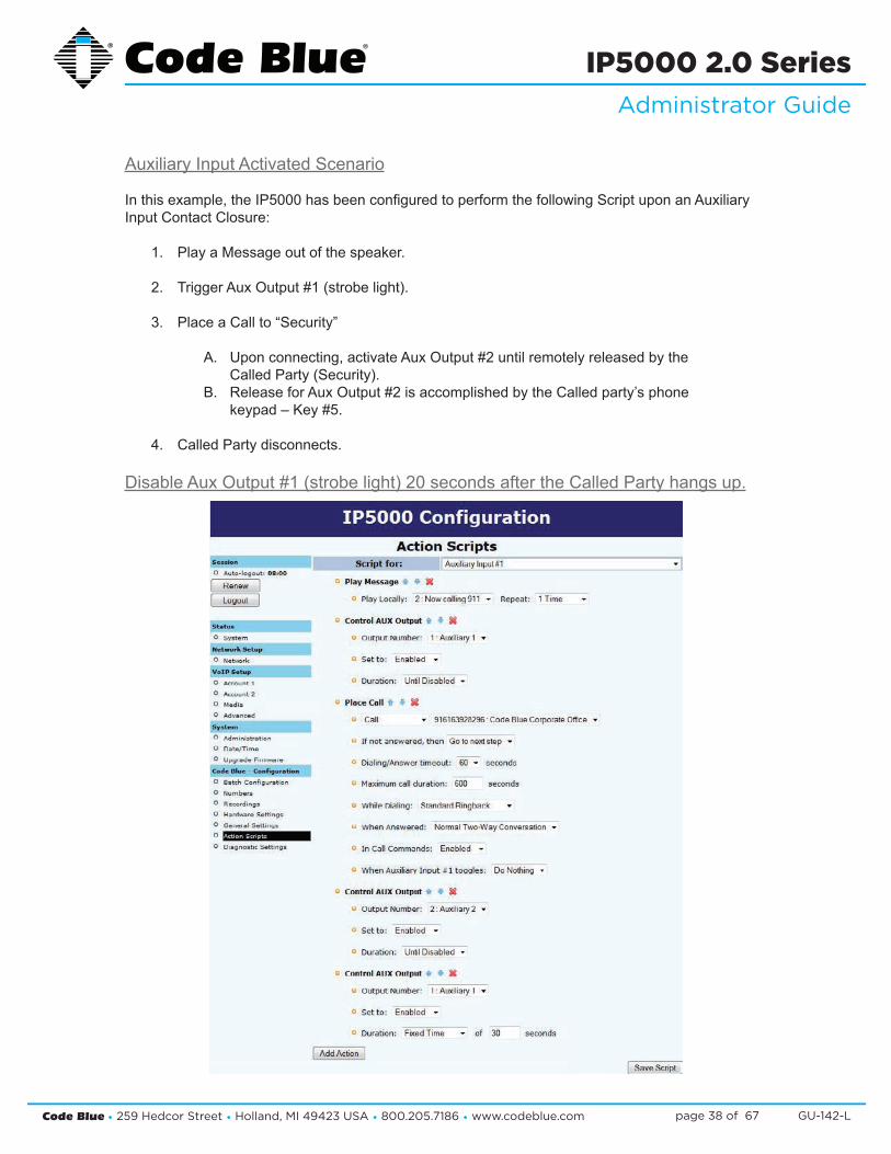
AuxiliaryInputActivatedScenario
Inthisexample,theIP5000hasbeenconfiguredtoperformthefollowingScriptuponanAuxiliaryInputContactClosure:
1. PlayaMessageoutofthespeaker.
2. TriggerAuxOutput#1(strobelight).
3. PlaceaCallto“Security”
A. Uponconnecting,activateAuxOutput#2untilremotelyreleasedbythe CalledParty(Security).B. ReleaseforAuxOutput#2isaccomplishedbytheCalledparty’sphone keypad–Key#5.
4. Called Party disconnects.
DisableAuxOutput#1(strobelight)20secondsaftertheCalledPartyhangsup.
Code Blue • 259 Hedcor Street • Holland, MI 49423 USA • 800.205.7186 • www.codeblue.com GU-142-Lpage 39 of 67
IP5000 2.0 SeriesAdministrator Guide
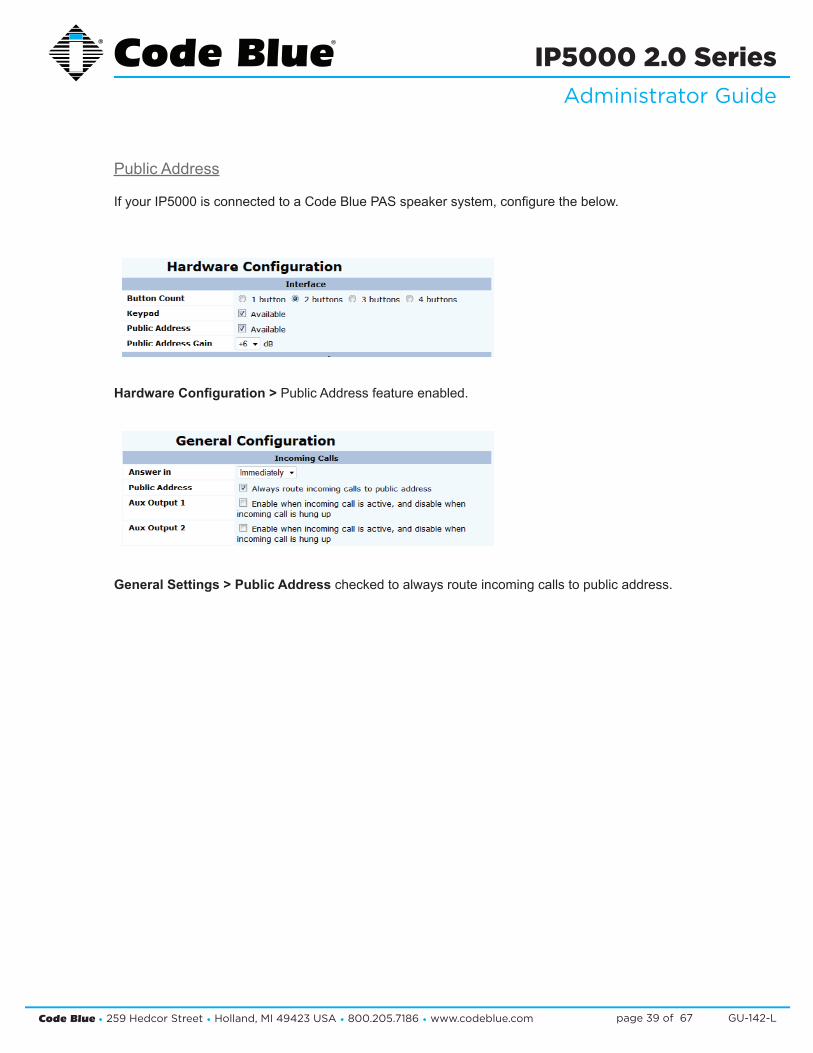
PublicAddress
IfyourIP5000isconnectedtoaCodeBluePASspeakersystem,configurethebelow.
Hardware Configuration >PublicAddressfeatureenabled.
General Settings > Public Addresscheckedtoalwaysrouteincomingcallstopublicaddress.
Public Address – PAS System If your IP5000 is connected to a Code Blue PAS speaker system, configure the below. Hardware Configuration > PublicAddressfeatureenabled
General Settings > Public Address checked to always route incoming alls topublicaddress
Public Address – PAS System If your IP5000 is connected to a Code Blue PAS speaker system, configure the below. Hardware Configuration > PublicAddressfeatureenabled
General Settings > Public Address checked to always route incoming alls topublicaddress

Code Blue • 259 Hedcor Street • Holland, MI 49423 USA • 800.205.7186 • www.codeblue.com GU-142-Lpage 40 of 67
IP5000 2.0 SeriesAdministrator Guide
CONFIGURINGDIAGNOSTICS
Diagnostic SettingsTheIP5000speakerphonediagnosticsettingsareconfiguredby:
• SelectingDiagnosticSettingsintheCodeBlueConfiguration.
• ClicktheEnablecheckbox.
• InputtheSNMPServerIPaddressandSNMPServerPortnumbertomonitortheIP5000withanSNMPmanagementsoftwareorwithCodeBlue’sToolVox®Gateway,w/UnitProgramming&Diagnostic(UPD)Software.
Power Supply Failure TimeoutTheIP5000monitorsthepowersourcesforlossofpoweror,inthecaseofthe12Volt/Battery,thecircuitmonitorsforLowVoltagecondition(11.5–11.0V).
Note:Backuppowermustbeavailableforthephonetoreportapowerfailure.Ifnopowerisavailable,anetworkmanagementsystemmustperiodicallycheckthephoneforthepowerfailuretobereported.CodeBlue’sUPDcanprovidethisfunction.
• PowersupplymonitoringisbasedontheselectionsmadeinHardwareSettings>PowerSupplysection.
• 12-24VoltA/CorD/Cmonitoringwillbecheckedwithinthetimeintervalprovided.(Example: 900seconds=15minutes.)Theintervalrange0-9999999(1second-2,777.7775hours),shouldthevoltagebecomeunavailableoraproblemhasbeendetected.TheCODEBLUE-MIB::powerSourceparameterwillbeissued.
• MainpowerMIBvalueisCODEBLUE-MIB::powerSource.0 ac.TheSNMPtrapwillbeissuedagainifatthenextintervalthevoltageissuehasnotbeenrectifiedwithinthetimedintervalanotherTrapwillbesent.TheACpowerfailurescriptwillalsoberun.
• 12VoltD/C-Batterymonitoringwillcheckthebatteryvoltageevery900secondsandreport avoltageconditionviaaSNMPtrap.
• 12VDCbatteryMIBvalueisCODEBLUE-MIB::powerSource.0 dc.Replacethefullychargedbatteryifpossible.Ifreplacingwithanunchargedbattery,allowupto48hoursforafullre-charge.TheDCpowerscriptwillalsoberun.
• PoEPowerFailure:WhenPoEpoweristhesolepowersourceandinterruptioninserviceisexperienced,noTrapwillbesentunlesstheIP5000hasasecondpowersourcetobackuptheIP5000operations.
Note:PoEpowerfailureswillonlybereportedifdataserviceisstillavailable.
• PoEPowerMIBvalueisCODEBLUE-MIB::powerSource.0 poe.ThePoEpowerfailurescriptwillalsoberun.
Code Blue • 259 Hedcor Street • Holland, MI 49423 USA • 800.205.7186 • www.codeblue.com GU-142-Lpage 41 of 67
IP5000 2.0 SeriesAdministrator Guide
Others – (Tests)
Microphonetestingisdisabledbydefault.Enablingwillshowanumberofreoccurringtestroutines.Themicrophoneissupportedbythespeaker’sabilitytogeneratetonesatthescheduleintervals.
• Thetestconsistsofbeepsfromthespeaker,whichwillbereceivedbythemicrophone. » Themaximumnumberofbeeps:2-10beeps. Oncethemicrophonedetectsthebeeps,thetestiscompleteuntilthenext scheduledtestispresent.
» Thebeeptonevolumechoicesaresoft,loud,orsofttoloud. Thebeeptonevolumesettingshouldbesettoanticipateambientnoiselevelatthetime of the test.
The test schedule choices are:• Every15minutes• Hourly• Daily• Weekly
• Testingondemand:Whenmicrophonespeakertestingisenabled,theadministratormayselecttoRunTestwhileloggedintotheIP5000.TheresultsofthetestwillonlybepresentinafailedSNMPtrap,whichwouldappearintheSNMPserverlogsorUPDDiagnosticReportslogs.TheMIBvalueisCODEBLUE-MIB::micSpeakerFailure.
PAS – Public Address System FailureTheIP5000monitorsthestateoftheCodeBlueBlueAlert®PASamplifiersforfailures.TheamplifierssignaltheIP5000ofaproblem,andtheIP5000sendsanSNMPtrapoftheproblem.
TheMIBvaluesfortheseSNMPtrapsare:
- CODEBLUE-MIB::publicAddressFailure
- CODEBLUE-MIB::highTemperature

Code Blue • 259 Hedcor Street • Holland, MI 49423 USA • 800.205.7186 • www.codeblue.com GU-142-Lpage 42 of 67
IP5000 2.0 SeriesAdministrator Guide
11 Dual Accounts
SampleApplicationusingDualAccountsontheIP5000phone
IfusingbothaccountsonanIP5000,youmustsetuptwonumbers(one“via Account 1”andtheother“via Account 2”),andanactionscriptwithasingledialstepwith“call first number”and“if not answered then call second number”.
Useoutcomesdependentonthenetwork:
1. Ifserver1isconsideredregisteredandresponds,thecallgoesthroughtoserver1 immediately.
2. Ifserver1isconsideredregisteredandunresponsive,itwillbetriedforuptoDialing/ answer timeout,butnomorethan30seconds.Thenserver2willbetried.
3. Ifserver1isnotconsideredregistered,server1willbeskippedandserver2willbetried immediately.

Code Blue • 259 Hedcor Street • Holland, MI 49423 USA • 800.205.7186 • www.codeblue.com GU-142-Lpage 43 of 67
IP5000 2.0 SeriesAdministrator Guide
12 CLI (Command Line Interface)TheIP5000hasextensivecommandsthatcanbeusedbytelnettingintothedevice.
Youcanusewindowstelnetordownloadacommonfreetelnetclient,“putty”.
TelnettotheIPAddressoftheIP5000phone:useport23ifunsure.
LoginisthesameasthroughtheWebGUI.
admin
admin
Youcantype“help”toseealistofavailablecommands.
The most commonly used are:
format c: codeblue –Usingthiscommand,youformatthephoneandreturnittofactorydefault.Thiscommandmustbefollowedupwithareboot.
reboot –Makethephonereboot.
ping IP Address or Domain Name–PingtheIPPBXtoseeifthephonecanreachitsregistrar.
button 1–Selectbutton1-4andinitiateabuttonpushremotely.Thisishandyforremotetesting.Button#1istheredbutton.Button#2istheblackbutton,ifequipped.
CLI (Command Line Interface)
The IP5000 has extensive commands that can be used by telnetting into the device.
You can use windows telnet or download a common free telnet client, “putty”.
Telnet to the IP Address of the IP5000 phone: use port 23 if unsure
Login is the same as through the Web GUI.
admin
admin
you can type “help” to see a list of available commands.
The most commonly used and helpful are:
format c: codeblue – using this command you format the phone and return it to factory default. This command must then be followed up with a reboot
reboot – make the phone reboot
ping IP Address or Domain Name – ping the IP PBX to see if the phone can reach it’s registrar
button 1 – select button 1-4 and initiate a button push remotely. This is very handy for remote testing. Button 1 is the red button. Button 2 is the black button if equipped.
Code Blue • 259 Hedcor Street • Holland, MI 49423 USA • 800.205.7186 • www.codeblue.com GU-142-Lpage 44 of 67
IP5000 2.0 SeriesAdministrator Guide
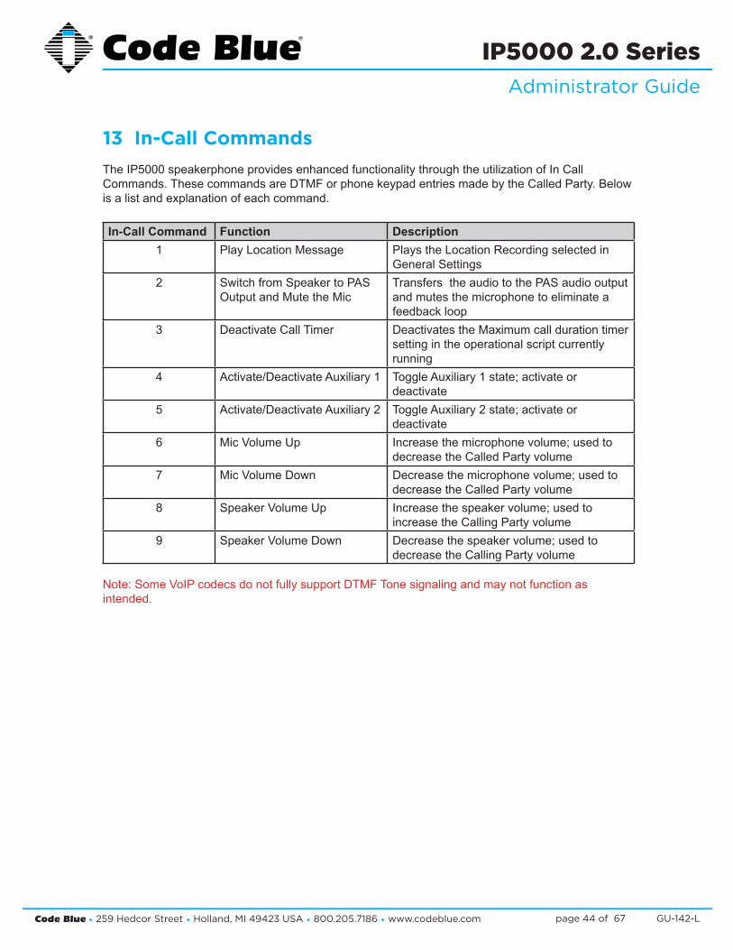
13 In-Call CommandsTheIP5000speakerphoneprovidesenhancedfunctionalitythroughtheutilizationofInCallCommands.ThesecommandsareDTMForphonekeypadentriesmadebytheCalledParty.Belowisalistandexplanationofeachcommand.
In-Call Command Function Description1 PlayLocationMessage Plays the Location Recording selected in
General Settings2 SwitchfromSpeakertoPAS
OutputandMutetheMicTransferstheaudiotothePASaudiooutputandmutesthemicrophonetoeliminateafeedbackloop
3 Deactivate Call Timer DeactivatestheMaximumcalldurationtimersettingintheoperationalscriptcurrentlyrunning
4 Activate/DeactivateAuxiliary1 ToggleAuxiliary1state;activateordeactivate
5 Activate/DeactivateAuxiliary2 ToggleAuxiliary2state;activateordeactivate
6 MicVolumeUp Increasethemicrophonevolume;usedtodecrease the Called Party volume
7 MicVolumeDown Decreasethemicrophonevolume;usedtodecrease the Called Party volume
8 SpeakerVolumeUp Increasethespeakervolume;usedtoincrease the Calling Party volume
9 SpeakerVolumeDown Decreasethespeakervolume;usedtodecrease the Calling Party volume
Note:SomeVoIPcodecsdonotfullysupportDTMFTonesignalingandmaynotfunctionasintended.
Code Blue • 259 Hedcor Street • Holland, MI 49423 USA • 800.205.7186 • www.codeblue.com GU-142-Lpage 45 of 67
IP5000 2.0 SeriesAdministrator Guide
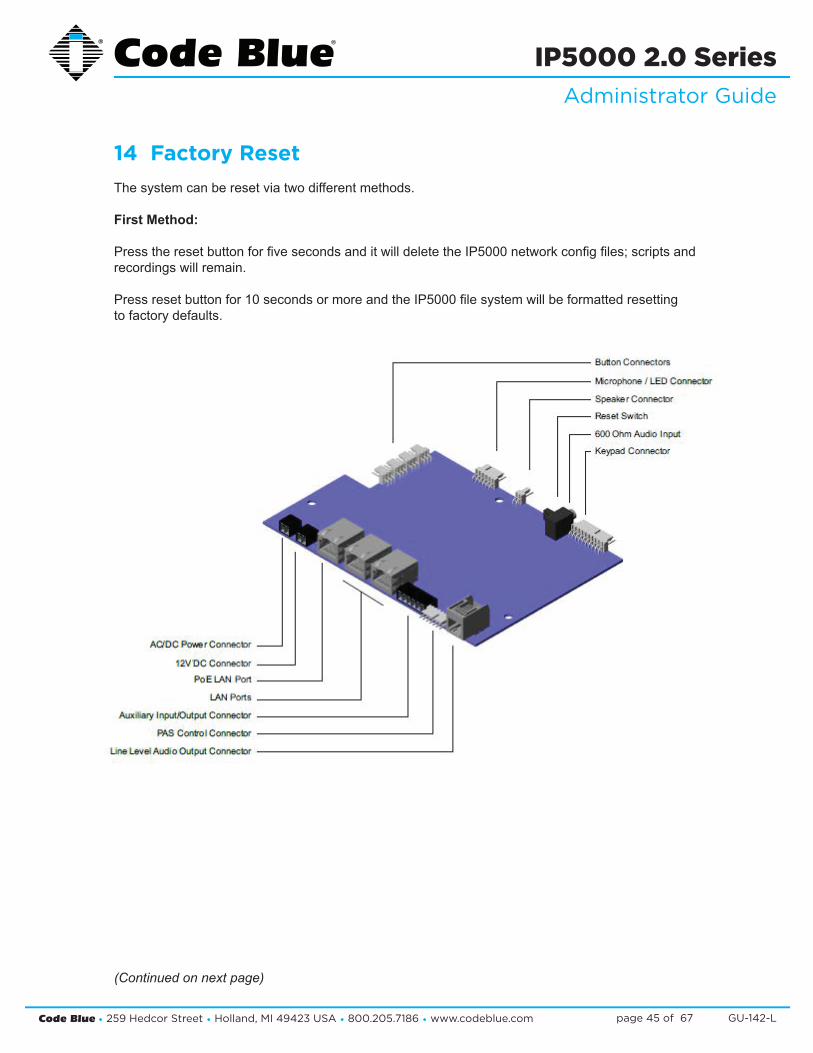
14 Factory ResetThesystemcanberesetviatwodifferentmethods.
First Method:
PresstheresetbuttonforfivesecondsanditwilldeletetheIP5000networkconfigfiles;scriptsandrecordings will remain.
Pressresetbuttonfor10secondsormoreandtheIP5000filesystemwillbeformattedresettingto factory defaults.
(Continued on next page)
Code Blue • 259 Hedcor Street • Holland, MI 49423 USA • 800.205.7186 • www.codeblue.com GU-142-Lpage 46 of 67
IP5000 2.0 SeriesAdministrator Guide
Factory Reset (continued)
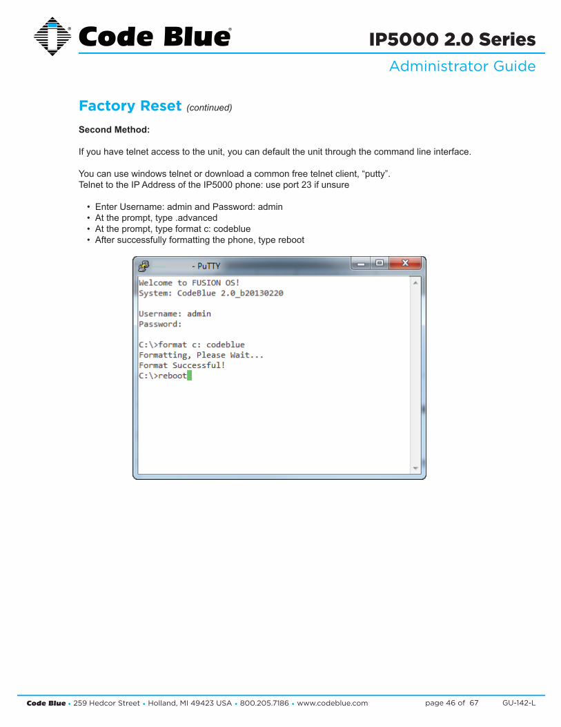
Second Method:
Ifyouhavetelnetaccesstotheunit,youcandefaulttheunitthroughthecommandlineinterface.
Youcanusewindowstelnetordownloadacommonfreetelnetclient,“putty”.TelnettotheIPAddressoftheIP5000phone:useport23ifunsure
• EnterUsername:adminandPassword:admin• Attheprompt,type.advanced• Attheprompt,typeformatc:codeblue• Aftersuccessfullyformattingthephone,typereboot
FACTORY RESET (continued)
2nd Method:
If you have telnet access totheunit,youcandefaulttheunitthroughthecommandline interface.
You can use windows telnet or download a common free telnet client, “putty”. Telnet to the IP Address of the IP5000 phone: use port 23 if unsure • EnterUsername:admin and Password: admin • Attheprompt,type.advanced • Attheprompt,typeformat c: codeblue • Aftersuccessfullyformattingthephone,typereboot
Code Blue • 259 Hedcor Street • Holland, MI 49423 USA • 800.205.7186 • www.codeblue.com GU-142-Lpage 47 of 67
IP5000 2.0 SeriesAdministrator Guide
15 CompatibilityTheIP5000phoneisaSIPversion2.0(RFC3261)deviceandiscompatiblewithIPGatewaysandPBXs that can register third Party SIP devices to them.
You must verify that the IP PBX you are registering the IP5000 to can handle Third Party SIP devices, whether through licensing and/or Hardware add-ons.
SomeexamplesofmainstreamIPPBXstheIP5000hasregisteredtoasaThirdPartySIPdeviceare:
AvayaAsteriskCiscoCallManagerNortel
and many others…

Code Blue • 259 Hedcor Street • Holland, MI 49423 USA • 800.205.7186 • www.codeblue.com GU-142-Lpage 48 of 67
IP5000 2.0 SeriesAdministrator Guide
PREPARATION
1. RecordtheMACaddressanddeterminethecurrentIPaddressforeachIP1500/2500/5000 deviceyouwishtousewithCUCM.
2. DeterminewhichpartitionyouwillputtheIP1500/2500/5000directorynumbersinto.
3. ObtainonedirectorynumberforeachIP1500/2500/5000device.
a. IfyouaregoingtousetheIP1500/2500/5000’sdualaccountconfigurationtoregis tertoredundantCUCMservers,obtainaseconddirectorynumberforeach IP1500/2500/5000device.
4. DeterminewhichcallingsearchspaceyouwillassigntotheIP1500/2500/5000.
IP5000 CONFIGURATION
RefertotheIP1500/2500/5000AdministrationANDUserGuidelocatedonourwebsite
Clear Existing Configuration
Ifnecessary,cleartheIP1500/2500/5000’sexistingconfiguration.ThiswillresetittoDHCP,somakesureyouhavethecapabilitytofindthedevice’sIPaddressagainifyoudothis.Foreachunit:
1. OpenaTelnetclientandconnecttotheIP1500/2500/5000.
2. Loginusingtheusernameadminandthedefaultpasswordadmin.
3. Typeformatc:codeblueandpressEnter.
4. TyperebootandpressEnter.
Configure Account(s)
1. LogintotheIP1500/2500/5000viaitswebinterface.Thedefaultusernameandpassword are admin and admin.
2. Select Account 1.
3. ForVoIPProtocol,selectSIP&RTP.
4. UnderSIPConfiguration,forUsername/Number,enterthedirectorynumberyouassigned earlier.
5. ForDisplayName,entercallerIDtext.
6. ForDomain,enterthehostnameorIPaddressoftheCUCMnodeyouwishtoregisterthis account to.
16 Configuring for Cisco Unified Communications Manager 9
Code Blue • 259 Hedcor Street • Holland, MI 49423 USA • 800.205.7186 • www.codeblue.com GU-142-Lpage 49 of 67
IP5000 2.0 SeriesAdministrator Guide
7. InsureKeep-Aliveisenabled.
8. UnderProxyAuthentication,forUsername,entertheusernameyouassignedtheCUCM enduser,e.g.thehexadecimalrepresentationoftheMACaddressorthelocal-usevariant for a secondary account.
9. ForPassword,enterthepasswordyouenteredintoDigestCredentialsundertheCUCM end user.
10. Click Save.
11. Repeatsteps3-10withAccount2ifyouareusingthesecondaccount.
Other Settings
RefertotheIP1500/2500/5000AdministrationANDUserGuidetocompletethesetupoftheIP1500/2500/5000,includingNumbers,GeneralSettings,HardwareSettings,andActionScripts.Whenfinished,clickApplyNowtorestartthephone;itshouldnowregistertoCUCMandbeabletoplacecallsintheassignedcallingsearchspaceaswellasreceivecallsatthedirectorynumberitisconfiguredwith.
Note: if you are setting up the IP1500/2500/5000 with secondary account support, make sure that you create each failover number twice.
UCM CONFIGURATION
AllUCM-sideconfigurationisdonewithintheCiscoUnifiedCMAdministrationwebinterface.
Create Phone Security Profile
1. NavigatetoSystem>Security>PhoneSecurityProfile.
2. DoaFindon“Third-party”tolocatetheThird-partySIPDeviceBasic-StandardSIPNon- SecureProfile.ClicktheCopyicon.
3. CheckEnableDigestAuthentication.
4. ChangetheNameandDescriptiontoCodeBlueIP1500-2500-5000Profile.
5. Click Save.
Configure End Users
ForeachIP5000device,configureanewenduserforSIPauthentication.
1. NavigatetoUserManagement>EndUser.
2. Click Add New.
3. FortheUserID,enterthehexadecimalversionoftheMACaddress;e.g.00:50:C2:17:7B:E8

Code Blue • 259 Hedcor Street • Holland, MI 49423 USA • 800.205.7186 • www.codeblue.com GU-142-Lpage 50 of 67
IP5000 2.0 SeriesAdministrator Guide
wouldbecome0050c2177be8.
a. UseoftheMACaddressasuserIDisonlyarecommendation.Iflocalconfiguration permits,youcanuseanyotherformofuserID;justbesuretorecordwhichuserID goeswithwhichphoneandwhichofthephone’saccounts.
4. FillintheLastnamefieldwithadescriptionofthestation.
5. CreateandrecordasecureSIPpasswordandfillintheDigestCredentialsandConfirm DigestCredentialsfieldswiththispassword.Youwillbeenteringthispasswordlaterinto theIP1500/2500/5000.
6. Click Save.
Configuring End Users for Secondary Accounts
IfyouaregoingtousetheIP1500/2500/5000’ssecondaryaccountfunctionalitytoregistertoaseparatedirectorynumbertoaseparateCUCMnodeforfailoversupport,repeattheaboveprocessusingalocal-use-onlyMACaddress.Alocal-use-onlyMACaddresshastheU/Lbitsetto1toindi-cate the address is locally administered.
SinceallIP1500/2500/5000units’MACaddressesstartwith0,youcancreatealocally-administeredaddressthatisunlikelytoconflictwithotherlocally-administeredaddressessimplybysettingtheU/Lbitsimplymeanschangingthesecond0toa2,e.g.0250c2177be8.
Configure Phones and Directory Numbers
ForeachIP5000device,configureanewPhoneandassociateddirectorynumber.
1. Navigate to Device > Phone.
2. Click Add New.
3. ForPhoneType,selectThird-partySIPDevice(Basic).
4. EntertheMACAddressofthephoneinhexadecimalformat;e.g.00:50:C2:17:7B:E8would become0050c2177be8.
5. ForDevicePool,selectDefault(orsomeotherlocally-configureddevicepool).
6. ForPhoneButtonTemplate,selectThird-partySIPDevice(Basic).
7. ForCallingSearchSpace,selectthecallingsearchspacetheIP1500/2500istouse.
8. ForDeviceSecurityProfile,selectCodeBlueIP1500-2500-5000Profile.
9. ForSIPProfile,selectStandardSIPProfile.
10. ForDigestUser,selecttheendusermatchingtheMACaddressofthephone,orthealter nateuserIDyoucreatedwhenyouwereconfiguringtheenduser.
Code Blue • 259 Hedcor Street • Holland, MI 49423 USA • 800.205.7186 • www.codeblue.com GU-142-Lpage 51 of 67
IP5000 2.0 SeriesAdministrator Guide
11. Click Save.
12. Ontheleftsideofthescreen,clickLine[1]-AddanewDN.
13. FillintheDirectoryNumber.
14. ForRoutePartition,selectthepartitionthedirectorynumberresidesin.
15.UnderLine1,forDisplay(InternalCallerID),enteradescriptivenameforCallerIDpur poses.
16. IfyouwishtoreturnabusysignalforsilentmonitoringiftheIP1500/2500/5000isinuse, disableCall Waiting:underMultipleCall/CallWaitingSettings,ForbothMaximumNumberofCallsand BusyTrigger,enter1.
17.Click Save.
Configuring Phones and Directory Numbers for Secondary Accounts
IfyouaregoingtousetheIP1500/2500/5000’ssecondaryaccountfunctionality,repeattheaboveprocesswithalocal-use-onlyMACaddressasoutlinedinConfiguringEndUsersforSecondaryAc-counts,andspecifyadistinctdirectorynumber.
Code Blue • 259 Hedcor Street • Holland, MI 49423 USA • 800.205.7186 • www.codeblue.com GU-142-Lpage 52 of 67
IP5000 2.0 SeriesAdministrator Guide
17 Avaya IP Office Integration Guide
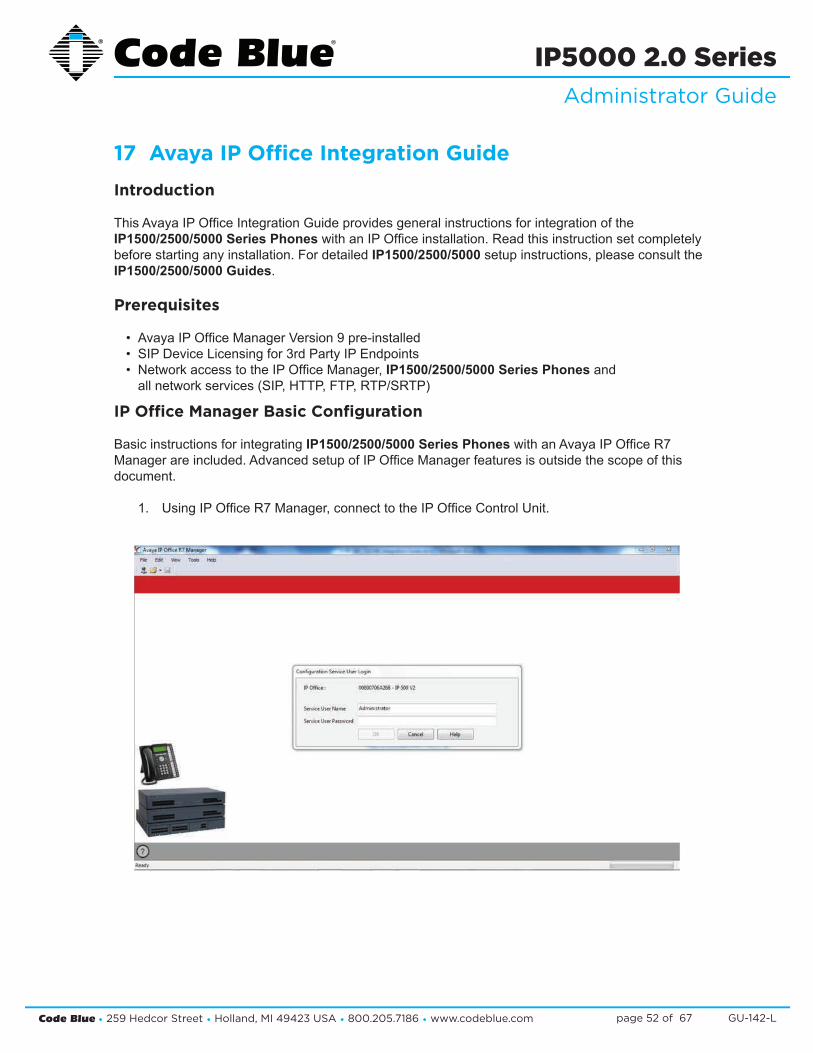
Introduction
ThisAvayaIPOfficeIntegrationGuideprovidesgeneralinstructionsforintegrationoftheIP1500/2500/5000 Series PhoneswithanIPOfficeinstallation.Readthisinstructionsetcompletelybeforestartinganyinstallation.FordetailedIP1500/2500/5000setupinstructions,pleaseconsulttheIP1500/2500/5000 Guides.
Prerequisites
• AvayaIPOfficeManagerVersion9pre-installed• SIPDeviceLicensingfor3rdPartyIPEndpoints• NetworkaccesstotheIPOfficeManager,IP1500/2500/5000 Series Phones and allnetworkservices(SIP,HTTP,FTP,RTP/SRTP)
IP Office Manager Basic Configuration
Basic instructions for integrating IP1500/2500/5000 Series PhoneswithanAvayaIPOfficeR7Managerareincluded.AdvancedsetupofIPOfficeManagerfeaturesisoutsidethescopeofthisdocument.
1. UsingIPOfficeR7Manager,connecttotheIPOfficeControlUnit.

Code Blue • 259 Hedcor Street • Holland, MI 49423 USA • 800.205.7186 • www.codeblue.com GU-142-Lpage 53 of 67
IP5000 2.0 SeriesAdministrator Guide
2. LogintoAvayaIPOfficeManager:
3. SIPExtensionSupportisrequiredforIP1500/2500/5000 integration. Select System > LAN1 (or LAN2) > VoIPinIPOfficeManager:

Code Blue • 259 Hedcor Street • Holland, MI 49423 USA • 800.205.7186 • www.codeblue.com GU-142-Lpage 54 of 67
IP5000 2.0 SeriesAdministrator Guide
4. Check that SIP Registrar Enableisenabled.
5. Select the SIP Registrarsub-tab.6. In Domain Name,entertheFullyQualifiedDomainName(FQDN)ortheIPad
dressassociatedwiththecorrectLANportontheIPOfficeControlUnit.Deselect Auto-create Extn/User. Click OK.

Code Blue • 259 Hedcor Street • Holland, MI 49423 USA • 800.205.7186 • www.codeblue.com GU-142-Lpage 55 of 67
IP5000 2.0 SeriesAdministrator Guide
7. ASIPextensionwillneedtobecreatedforeachIP1500/2500/5000 Series Phone. Right click on Extension,selectNew and then click on SIP Extension.
8. Enterthefollowingfieldstocreateanewextension: • Extension ID: AuniqueextensiontoidentifythelogicalextensioninIPOffice.By default,IPextensionsstartat8000. • Base Extension: This is the extension used to call the IP1500/2500/5000 Series Phone. • Force Authorization: Select to force authentication of the IP1500/2500/5000 Series Phone.

Code Blue • 259 Hedcor Street • Holland, MI 49423 USA • 800.205.7186 • www.codeblue.com GU-142-Lpage 56 of 67
IP5000 2.0 SeriesAdministrator Guide
9. Select the VoIPtabandselecttheCompression Mode. The default of the IP1500/2500/5000 Series Phone is G.711 U-LAW and will work in most cases. MoreinformationonaudiocodecscanbefoundintheIP1500/2500/5000 Series Phone Guides. Set DTMF Support to RFC2833.
10. EachIP1500/2500/5000 Series Phone should have a unique User. Right click on User and select New.
Code Blue • 259 Hedcor Street • Holland, MI 49423 USA • 800.205.7186 • www.codeblue.com GU-142-Lpage 57 of 67
IP5000 2.0 SeriesAdministrator Guide
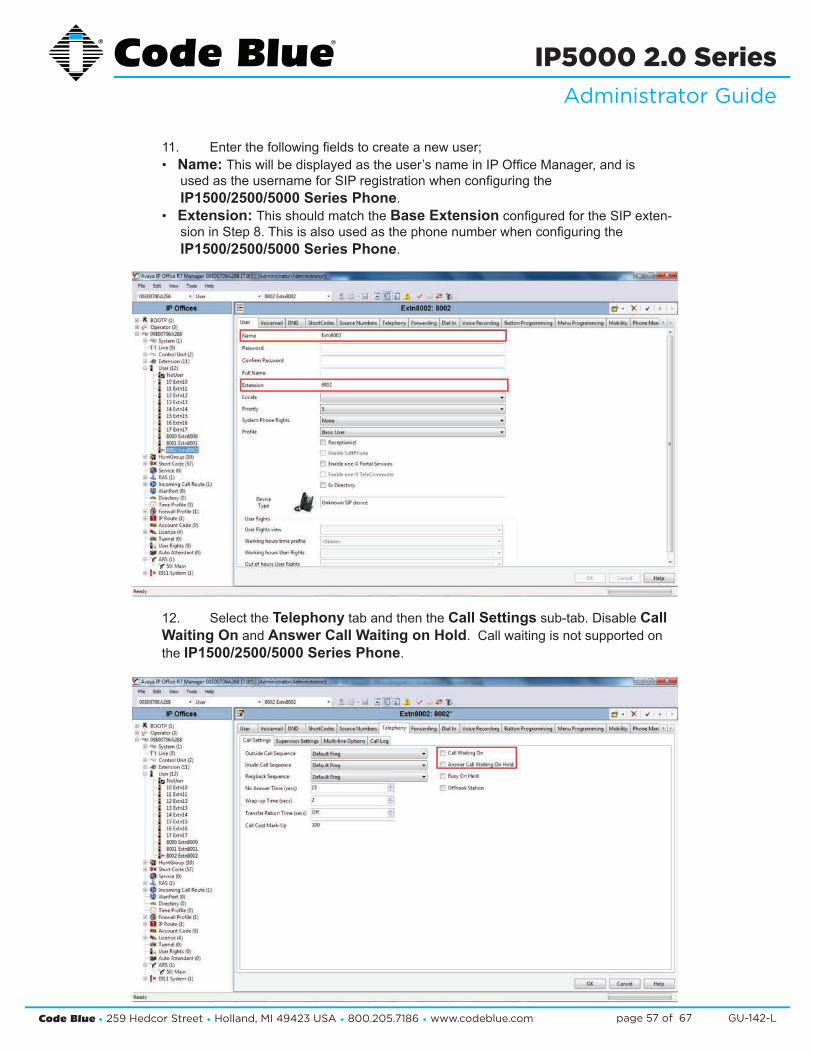
11. Enterthefollowingfieldstocreateanewuser; • Name: Thiswillbedisplayedastheuser’snameinIPOfficeManager,andis usedastheusernameforSIPregistrationwhenconfiguringthe IP1500/2500/5000 Series Phone. • Extension: This should match the Base ExtensionconfiguredfortheSIPexten- sioninStep8.Thisisalsousedasthephonenumberwhenconfiguringthe IP1500/2500/5000 Series Phone.
12. Select the TelephonytabandthentheCall Settingssub-tab.DisableCall Waiting On and Answer Call Waiting on Hold.Callwaitingisnotsupportedon the IP1500/2500/5000 Series Phone.

Code Blue • 259 Hedcor Street • Holland, MI 49423 USA • 800.205.7186 • www.codeblue.com GU-142-Lpage 58 of 67
IP5000 2.0 SeriesAdministrator Guide
13. Select the Supervisor sub-tab.IntheLogin Codefieldenterapasswordtobe usedbytheIP1500/2500/5000 Series Phoneforauthentication.AvayaIPOffice willonlyacceptnumbersinthisfield.
14. IfaddingmultipleIP1500/2500/5000 Series Phones,repeatSteps7-13foreach device.

Code Blue • 259 Hedcor Street • Holland, MI 49423 USA • 800.205.7186 • www.codeblue.com GU-142-Lpage 59 of 67
IP5000 2.0 SeriesAdministrator Guide
18 IP Audio InterfaceTheIPAudioInterface(IAI)isanIP-basedaudiodevicesupportingVoIPandAudiooverIPapplications.TheIAIfullduplextechnologyisthemostadvancedonthemarkettoday.ItisanidealsolutionforbridgingaudioandcontactclosuresoverlongdistanceLAN/WANnetworks.Itextendsandinterfacestonon-networkbasedtraditionalpublicaddresssys-temsandallowsfortwo-waycommunicationwithexistingfirepanelssotheymaybeusedasemergencyendpoints.TheIAIisdesignedtosupportCodeBlue’sBlueAlert®MassNotifica-tion System over the wired or wireless network.
BlueAlert,NFPA72®ECS(Chapter24)compliant,allowsflex-ibilityinannouncementdeliverybyprovidingtexttospeech,livebroadcast,pre-recordedmessagesandwarningtoneoptions,aswellasannouncementrepeatandschedulingfeatures.
ThefollowingareexamplesofhowtosetuptheIAIandinterfacewithbothlinelevelaudioanda25/70volt PA system.
Optionalsoftwareallowsmultipleunittemplateprogramming,audiostorage,phoneandpublicaddressemailfaultreporting,andmanagesallincomingemergencyandnon-emergencyeventswithaneasy-to-useGraphicalUserInterface.CodeBlue’sIAIfulfillstheneedforeffective,reliableemergencynetworkcommunication and enhances full system integration.
• TheLineLevelAudioInputorOutputcanbeutilizedbyconnectingtopins1-4ofthePhoenixPlug.
• TheAuxiliaryOutputisutilizedtoactivateacontactclosureona3rdpartysystemtypicallytoactivateagroupofaudiopagingdevicesorwaketheaudioamplificationsystemfromasleepmodeandthenpassaudiofromtheBlueAlertsystemtothe3rdpartysystemconnectedtoLineLevelAudioOutput.
• TheAuxiliaryInputisutilizedtoinitiateacalltoaBlueAlertgroupandpassaudiofromtheactivatingsystem,connectedtotheLineLevelAudioInput,todevicesconfiguredwithintheBlueAlertgroup
Page 12 of 28 PR-108-A 1/2012
4) The IAI is capable of being utilized in various configurations connecting up multiple types of audio systems to be utilized as a mass notification endpoint within the Blue Alert system. Below is an overview of the connections of the IAI:
Figure 8
• The Line Level Audio Input or Output can be utilized by connecting to pins 1-4 of the Phoenix Plug.
• The Auxiliary Output is utilized to activate a contact closure on a 3rd party system typically to activate a group of audio paging devices or wake the audio amplification system from a sleep mode and then pass audio from the Blue Alert system to the 3rd party system connected to Line Level Audio Output.
• The Auxiliary Input is utilized to initiate a call to a Blue Alert group and pass audio from the activating system, connected to the Line Level Audio Input, to devices configured within the Blue Alert group
• Various devices exist on the market to convert 25/70/100 volt audio to line level audio. See Appendix B for examples. However, the IAI requires a 600ohm input. It is the responsibility of the end user to convert if necessary.
Code Blue • 259 Hedcor Street • Holland, MI 49423 USA • 800.205.7186 • www.codeblue.com GU-142-Lpage 60 of 67
IP5000 2.0 SeriesAdministrator Guide
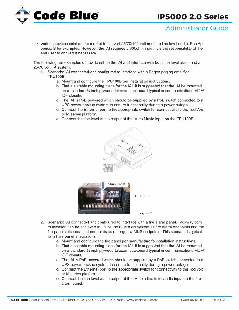
• Variousdevicesexistonthemarkettoconvert25/70/100voltaudiotolinelevelaudio.SeeAp-pendixBforexamples.However,theIAIrequiresa600ohminput.Itistheresponsibilityoftheend user to convert if necessary.
ThefollowingareexamplesofhowtosetuptheIAIandinterfacewithbothlinelevelaudioanda25/70voltPAsystem.
1. Scenario:IAIconnectedandconfiguredtointerfacewithaBogenpagingamplifier TPU100B.
a. MountandconfiguretheTPU100Bperinstallationinstructions.b. FindasuitablemountingplacefortheIAI.ItissuggestedthattheIAIbemounted
onastandard¾inchplywoodtelecombackboardtypicalincommunicationsMDF/ IDF closets.
c. TheIAIisPoEpoweredwhichshouldbesuppliedbyaPoEswitchconnectedtoa UPSpowerbackupsystemtoensurefunctionalityduringapoweroutage.
d. ConnecttheEthernetporttotheappropriateswitchforconnectivitytotheToolVox orMseriesplatform.
e. ConnectthelinelevelaudiooutputoftheIAItoMusicinputontheTPU100B.
2. Scenario:IAIconnectedandconfiguredtointerfacewithafirealarmpanel.Two-waycom municationcanbeachievedtoutilizetheBlueAlertsystemasfirealarmendpointsandthe firepanelvoiceenabledendpointsasemergencyMNSendpoints.Thisscenarioistypical forallfirepanelintegrations:
a. Mountandconfigurethefirepanelpermanufacturer’sinstallationinstructions.b. FindasuitablemountingplacefortheIAI.ItissuggestedthattheIAIbemounted
onastandard¾inchplywoodtelecombackboardtypicalincommunicationsMDF/ IDF closets.
c. TheIAIisPoEpoweredwhichshouldbesuppliedbyaPoEswitchconnectedtoa UPSpowerbackupsystemtoensurefunctionalityduringapoweroutage.
d. ConnecttheEthernetporttotheappropriateswitchforconnectivitytotheToolVox orMseriesplatform.
e. ConnectthelinelevelaudiooutputoftheIAItoalinelevelaudioinputonthefire alarmpanel.
Page 13 of 28 PR-108-A 1/2012
The following are examples of how to set up the IAI and interface with both line level audio and a 25/70 volt PA system.
a. Scenario: IAI connected and configured to interface with a Bogen paging amplifier TPU100B.
1. Mount and configure the TPU100B per installation instructions.
2. Find a suitable mounting place for the IAI. It is suggested that the IAI be mounted on a standard ¾ inch plywood telecom backboard typical in communications MDF/IDF closets.
3. The IAI is PoE powered which should be supplied by a PoE switch connected to a UPS power backup system to ensure functionality during a power outage.
4. Connect the Ethernet port to the appropriate switch for connectivity to the ToolVox or M series platform.
5. Connect the line level audio output of the IAI to Music input on the TPU100B.
Figure 9
Music Input
TPU100B

Code Blue • 259 Hedcor Street • Holland, MI 49423 USA • 800.205.7186 • www.codeblue.com GU-142-Lpage 61 of 67
IP5000 2.0 SeriesAdministrator Guide
Page 19 of 28 PR-108-A 1/2012
7. Connect the auxiliary output of the IAI to a contact closure input on the fire panel.Note: Some fire panels may require a signaling device be placed on the dry contact closure of the IAI to send the active/inactive signaling to the panel. Please refer to your fire panels manufacturing specifications for proper connectivity. See Appendix B for additional options supplied by end user.Signaling relay example:
Figure 18
8. Connect a normally open contact closure on the fire panel to the auxiliary input on the IAI.
9. Configure your IAI to place a call to the appropriate Blue Alert group when the Auxiliary #1 input is activated allowing the fire panel to pass audio to all endpoints configured in the Blue Alert group. Ensure that Disconnect is chosen when Auxiliary Input #1 toggles.
Figure 19
f. Connectthelinelevelaudiooutputofthefirepaneltothelinelevelaudioinputon the IAI. Note:Somepanelsmayrequirea25/70voltinput.RefertoAppendixBforaudio linelevelconvertersandaudioenabledrelayswhicharetobesuppliedbytheend user.
g. ConnecttheauxiliaryoutputoftheIAItoacontactclosureinputonthefirepanel. Note:Somefirepanelsmayrequireasignalingdevicebeplacedonthedrycontact closureoftheIAItosendtheactive/inactivesignalingtothepanel.Pleasereferto yourfirepanelsmanufacturingspecificationsforproperconnectivity.SeeAppendix Bforadditionaloptionssuppliedbyenduser. Signalingrelayexample:
h. Connectanormallyopencontactclosureonthefirepaneltotheauxiliaryinputon the IAI.
i. ConfigureyourIAItoplaceacalltotheappropriateBlueAlertgroupwhentheAuxil iary#1inputisactivatedallowingthefirepaneltopassaudiotoallendpointscon figuredintheBlueAlertgroup.EnsurethatDisconnectischosenwhenAuxiliary Input#1toggles.
Page 18 of 28 PR-108-A 1/2012
b. Scenario: IAI connected and configured to interface with a fire alarm panel.Two-way communication can be achieved to utilize the Blue Alert system as fire alarm endpoints and the fire panel voice enabled endpoints as emergency MNS endpoints. This scenario is typical for all fire panel integrations:
1. Mount and configure the fire panel per manufacturer’sinstallation instructions.
2. Find a suitable mounting place for the IAI. It is suggested that the IAI be mounted on a standard ¾ inch plywood telecom backboard typical in communications MDF/IDF closets.
3. The IAI is PoE powered which should be supplied by a PoE switch connected to a UPS power backup system to ensure functionality during a power outage.
4. Connect the Ethernet port to the appropriate switch for connectivity to the ToolVox or M series platform.
5. Connect the line level audio output of the IAI to a line level audio input on the fire alarm panel.
6. Connect the line level audio output of the fire panel to the line level audio input on the IAI.Note: Some panels may require a 25/70 volt input. Refer to Appendix B for audio line level converters and audio enabled relays which are to be supplied by the end user.
Figure 17Line LevelAudio Input
Line LevelAudio Input

Code Blue • 259 Hedcor Street • Holland, MI 49423 USA • 800.205.7186 • www.codeblue.com GU-142-Lpage 62 of 67
IP5000 2.0 SeriesAdministrator Guide
j. EnsurethatcallsarealwaysroutedtoPublicAddressunderGeneralSettingsofthe IAI.ThiswillpassaudiotothefirepanelduringaBlueAlertannouncement.
k. EnsureAuxiliaryInput#1andAuxiliaryOutput#1areAvailableintheIAIsettings.
l. Programacontactclosureonthefirepaneltoactivatethedesiredvoiceenabled endpointsandpasstheIAIaudiotothem.
m. ProgramacontactclosureonthefirepaneltoactivatetheIAIandpassthefire panelaudiototheIAI.
Page 20 of 28 PR-108-A 1/2012
10. Ensure that calls are always routed to Public Address under General Settings of the IAI. This will pass audio to the fire panel during a Blue Alert announcement.
Figure 20
11. Ensure Auxiliary Input #1 and Auxiliary Output #1 are Available in the IAI settings.
Figure 21
12. Program a contact closure on the fire panel to activate the desired voice enabled endpoints and pass the IAI audio to them.
13. Program a contact closure on the fire panel to activate the IAI and pass the fire panel audio to the IAI.
14. On the following pages are screen shots of a Simplex Grinnell 4100U fire panel programming to work with the Code Blue IAI as an integrated 2 way emergency mass notification system.

Code Blue • 259 Hedcor Street • Holland, MI 49423 USA • 800.205.7186 • www.codeblue.com GU-142-Lpage 63 of 67
IP5000 2.0 SeriesAdministrator Guide
19 Button and Activation Specifications
Thebuttonrequiresaforceof3-5N(Newton-siunits).Anotherwaytoexplainthis:6–18ozofpressureovertimeapplied,whichisbetween125–300ms(0.15–0.3seconds).
Slappingorslidingyourfingersacrossthebuttonwillnotactivateit.Itrequirespressureovertime.Theouteredgeofthebuttonwillnotbethatsensitive.Normaluseofthebuttonwouldbesomeonerushingtoactivateitandusingtheirhand,finger,arm,knee,forehead,etc. Nootherpiezoelectricbuttononthemarketwillfunctionaswell.
TheonlydifferencesbetweentheanalogandIPbuttonsaretheoutputonthewiresandthestateofthebutton,N.OorN.C.Thebuttoncanandpiezoelementsareidentical.Theanalogbutton(2wire)isN.O.(NormallyOpen),andclosesmomentarilywhenpressed.Thedigitalbutton(3wire)isN.C.(NormallyClosed)andwhenpressedthestategoestoopenmomentarily,whichistranslatedtoaPthenRdataoutputtotheIP1500/IP2500/IP5000boards.
Thespecificationofthebuttonis:
Switching Current: 0.200 A
Actuation Force:3-5N:6–18ozofpressureovertimeapplied.Whichisbetween125–300ms(0.15–0.3seconds)
Make Impulse Time:125-300mSEC
Switch Resistance : “ON”<20ohms
Switch Resistance: “OFF”>5MOhms
Make Pulse Time: 125-300mSEC
Surface Deflection: 1 micron - activation
Button Temperature : -40°Cto+85°C(-40°Fto185°F)
Functional Life: >50millionactivations
Functional in Freezing Rain: Yes
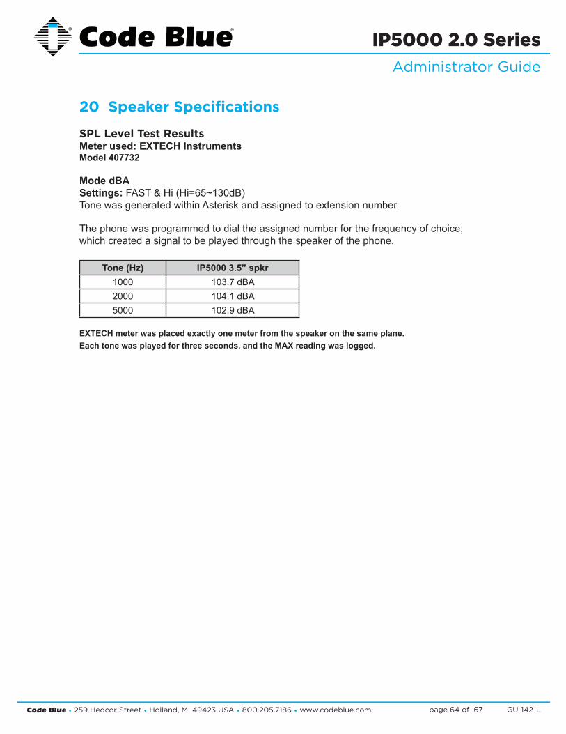
Code Blue • 259 Hedcor Street • Holland, MI 49423 USA • 800.205.7186 • www.codeblue.com GU-142-Lpage 64 of 67
IP5000 2.0 SeriesAdministrator Guide
20 Speaker Specifications
SPL Level Test ResultsMeter used: EXTECH InstrumentsModel 407732
Mode dBASettings:FAST&Hi(Hi=65~130dB)TonewasgeneratedwithinAsteriskandassignedtoextensionnumber.
Thephonewasprogrammedtodialtheassignednumberforthefrequencyofchoice,whichcreatedasignaltobeplayedthroughthespeakerofthephone.
Tone (Hz) IP5000 3.5” spkr1000 103.7dBA2000 104.1 dBA5000 102.9 dBA
EXTECH meter was placed exactly one meter from the speaker on the same plane.Each tone was played for three seconds, and the MAX reading was logged.

Code Blue • 259 Hedcor Street • Holland, MI 49423 USA • 800.205.7186 • www.codeblue.com GU-142-Lpage 65 of 67
IP5000 2.0 SeriesAdministrator Guide
21 Troubleshooting the IP5000 SpeakerphoneTheIP5000speakerphoneisanetworkdevice.Thefollowingaretipsfortroubleshooting:
Power-Ensurethepowertoyourdeviceisworkingandratedfor802.11af/atPoEspecificationsifusingPOE.TheIP5000shouldonlyhaveonesourceofpowerotherthanabackupbattery.IfnotusingPOE,thenmainpowerneedstofallinto12-24VoltsACorDC.
Ping Test-ThisdeterminesconnectivityandthepacketlossandlatencytimetoandfromyourdestinationandthequalityofyournetworkconnectiontotheIP5000.Ifyoureceivenoresponseandpowerisconfirmed,contactyournetworkadministrator.YoucanalsoPingfromwithinthephonetowardsyourIPPBXtotestthatitcanreachitsIPPBX/SIPGateway.
Network–Ifyou’reputtingtheIP5000onanetworkthatrestrictsportsthenthebelowportsmustbeopenfortheIP5000tocommunicatetoitsappropriateIPPBX/SIPGateway.
1. IAX2/UDPoutgoingtoport4569onIPPBX/SIPGateway(onlyneededifusingIAX2instead ofSIPontheaccountspage).
2. SIP/UDPoutgoingtoport5060IPPBX/SIPGateway.3. RTP/UDPincomingfromIPPBX/SIPGatewaytoUDPports23456-23556(configurable).
DHCP-TheIP5000issetupforDHCPbydefault.IfyoucannotdeterminetheIPaddressofyourIP5000,contactyournetworkadministrator.
Account-EnsureyourSIPorIAX2accountissetupcorrectly.AccountusernameandpasswordmustmatchtheaccountcredentialsonyourVoIPsystem.ThisisthemostcommonmistakewithsettingupSIPaccounts.
Codec-EnsurethecodecsettingsonyourVoIPsystemmatchtheIP5000codecsettings.
Firewall-FirewallscommonlyblockorpartiallyblockVoIPcalls.CheckwithyournetworkadministratorifyoucannotcommunicatewithyourIP5000frombehindafirewall.
ContactinfoforCodeBlueTechnicalServicesandSupportstaffcanbelocatedattheendofthisGuideifyouneedfurtherassistancetroubleshootingyourIP5000phone.Dependingonyourissue,afirmwareupgrademaybeneeded.
Note:IfyoudonothaveaDHCPserverrunning,useastandardhome/wirelessrouterandplugyourspeakerphoneandlaptopintothesamerouter.OnceyouknowtheIPAddress,youcanbrowsetoitviayourwebbrowser.

Code Blue • 259 Hedcor Street • Holland, MI 49423 USA • 800.205.7186 • www.codeblue.com GU-142-Lpage 66 of 67
IP5000 2.0 SeriesAdministrator Guide
22 Regulatory & Warranty
RegulatoryTheIP5000speakerphoneconformstothefollowinglistofdirectivesandproductsafetystandardsasapplicable:
EU: EN 55022:2006+A1:2007EN 55024:1998+A1:2001+A2:2003EN 61000-4-2:1995EN 61000-4-3:2006+A1:2008EN 61000-4-4:2004EN 61000-4-5:2006EN 61000-4-6:2007EN 61000-4-8:1993+A1:2001EN 61000-4-11:2004EN 61000-3-2:2006+A1:2007EN 61000-3-3:2008
USA: CFR 47, Part 15CANADA: ICES-003e
WarrantyCodeBlueCorporationprovidesalimitedwarrantyonthisproduct.Refertoyoursalesagreementtoestablishthetermsofthelimitedwarranty.Inaddition,CodeBlue’sstandardwarrantylanguage,aswellasinformationregardingsupportforthisproduct,whileunderwarranty,isavailableatwww.codeblue.com/support.
Notice : Every effort was made to ensure that the information in this document was complete and accurate at the time of printing. However, information is subject to change.

Code Blue • 259 Hedcor Street • Holland, MI 49423 USA • 800.205.7186 • www.codeblue.com GU-142-Lpage 67 of 67
IP5000 2.0 SeriesAdministrator Guide
23 Technical Services and SupportForadditionalsupport,pleasefeelfreetocontactCodeBlue’sTechnicalServicesandSupportStaffat [email protected] or (616) 392-8296, Opt 3.
8 a.m. to 5 p.m. Monday through Friday Eastern Time