Embed Size (px)
Citation preview

USER MANUAL
T E K N I C , I N C P H O N E ( 5 8 5 ) 7 8 4 - 7 4 5 4
IPC-3 AND IPC-5 POWER SUPPLIES
VERSION 2.03 MAY 18, 2020

2
THIS PAGE INTENTIONALLY LEFT BLANK
3
TABLE OF CONTENTS TABLE OF CONTENTS................................................... 3 INTRODUCTION ............................................................ 4
Features..........................................................................................4 Symbols Used in This Document ..................................................5
SAFETY INFORMATION.................................................. 6 Precautionary Statement ...............................................................6 General Disclaimer ........................................................................6 IPC-3 Special Safety Note .............................................................. 7 General Safety Instructions ........................................................... 7
PARTS OF AN IPC-3 / IPC-5 ......................................... 9 Parts, Mating Connectors, and Pinouts.........................................9
IPC USE INSTRUCTIONS ............................................. 10 Mounting Orientation.................................................................. 10 How To Connect IPC To A Load...................................................11 How To Disconnect IPC From A Load .........................................11 Additional Use Notes ....................................................................11
CABLES .................................................................... 12 IPC-3 & IPC-5 Accessory Cables.................................................. 12
APPENDIX A: LED CODES ......................................... 13 APPENDIX B: SPECIFICATIONS.................................... 14 APPENDIX C: MECHANICAL REFERENCE ..................... 15
Mounting Dimensions (IPC-3 and IPC-5)................................... 15 Mounting a Third-Party Fan (IPC-5 Only).................................. 16
Top Mount Fan (40mm x 40mm) ................................... 16 Side Mount Fan (80mm x 80mm) .................................. 17 DIN Rail Adapter (Optional, Third-Party) ...................... 18
APPENDIX D: MISCELLANEOUS TOPICS....................... 19 How to Modify AC Line Cord For Use With 220VAC ................. 19 Installing An AC Line Filter For CE Emissions Compliance ......20
I P C - 3 , I P C- 5 U S E R M A N U A L R E V . 2 . 0 3 4
TEKNIC, INC. PHONE (585)784-7454
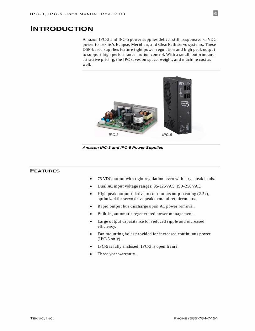
INTRODUCTION Amazon IPC-3 and IPC-5 power supplies deliver stiff, responsive 75 VDC power to Teknic's Eclipse, Meridian, and ClearPath servo systems. These DSP-based supplies feature tight power regulation and high peak output to support high performance motion control. With a small footprint and attractive pricing, the IPC saves on space, weight, and machine cost as well.
IPC-5IPC-3
Amazon IPC-3 and IPC-5 Power Supplies
FEATURES • 75 VDC output with tight regulation, even with large peak loads.
• Dual AC input voltage ranges: 95-125VAC; 190-250VAC.
• High peak output relative to continuous output rating (2.5x), optimized for servo drive peak demand requirements.
• Rapid output bus discharge upon AC power removal.
• Built-in, automatic regenerated power management.
• Large output capacitance for reduced ripple and increased efficiency.
• Fan mounting holes provided for increased continuous power (IPC-5 only).
• IPC-5 is fully enclosed; IPC-3 is open frame.
• Three year warranty.
I P C - 3 , I P C- 5 U S E R M A N U A L R E V . 2 . 0 3 5
TEKNIC, INC. PHONE (585)784-7454
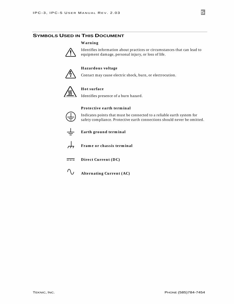
SYMBOLS USED IN THIS DOCUMENT Warning
Identifies information about practices or circumstances that can lead to equipment damage, personal injury, or loss of life.
Hazardous voltage
Contact may cause electric shock, burn, or electrocution.
Hot surface
Identifies presence of a burn hazard.
Protective earth terminal
Indicates points that must be connected to a reliable earth system for safety compliance. Protective earth connections should never be omitted.
Earth ground terminal
Frame or chassis terminal
Direct Current (DC)
Alternating Current (AC)
I P C - 3 , I P C- 5 U S E R M A N U A L R E V . 2 . 0 3 6
TEKNIC, INC. PHONE (585)784-7454
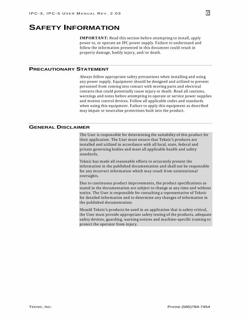
SAFETY INFORMATION IMPORTANT: Read this section before attempting to install, apply power to, or operate an IPC power supply. Failure to understand and follow the information presented in this document could result in property damage, bodily injury, and/or death.
PRECAUTIONARY STATEMENT Always follow appropriate safety precautions when installing and using any power supply. Equipment should be designed and utilized to prevent personnel from coming into contact with moving parts and electrical contacts that could potentially cause injury or death. Read all cautions, warnings and notes before attempting to operate or service power supplies and motion control devices. Follow all applicable codes and standards when using this equipment. Failure to apply this equipment as described may impair or neutralize protections built into the product.
GENERAL DISCLAIMER The User is responsible for determining the suitability of this product for their application. The User must ensure that Teknic’s products are installed and utilized in accordance with all local, state, federal and private governing bodies and meet all applicable health and safety standards.
Teknic has made all reasonable efforts to accurately present the information in the published documentation and shall not be responsible for any incorrect information which may result from unintentional oversights.
Due to continuous product improvements, the product specifications as stated in the documentation are subject to change at any time and without notice. The User is responsible for consulting a representative of Teknic for detailed information and to determine any changes of information in the published documentation.
Should Teknic’s products be used in an application that is safety critical, the User must provide appropriate safety testing of the products, adequate safety devices, guarding, warning notices and machine-specific training to protect the operator from injury.
I P C - 3 , I P C- 5 U S E R M A N U A L R E V . 2 . 0 3 7
TEKNIC, INC. PHONE (585)784-7454
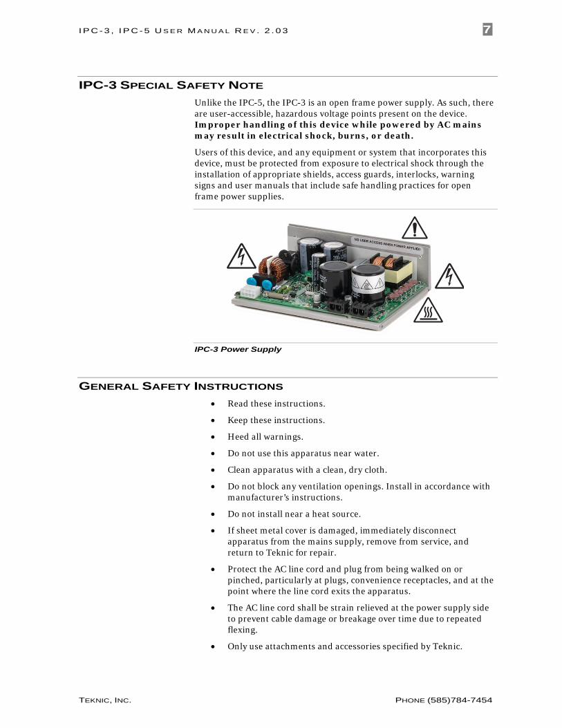
IPC-3 SPECIAL SAFETY NOTE Unlike the IPC-5, the IPC-3 is an open frame power supply. As such, there are user-accessible, hazardous voltage points present on the device. Improper handling of this device while powered by AC mains may result in electrical shock, burns, or death.
Users of this device, and any equipment or system that incorporates this device, must be protected from exposure to electrical shock through the installation of appropriate shields, access guards, interlocks, warning signs and user manuals that include safe handling practices for open frame power supplies.
IPC-3 Power Supply
GENERAL SAFETY INSTRUCTIONS • Read these instructions.
• Keep these instructions.
• Heed all warnings.
• Do not use this apparatus near water.
• Clean apparatus with a clean, dry cloth.
• Do not block any ventilation openings. Install in accordance with manufacturer’s instructions.
• Do not install near a heat source.
• If sheet metal cover is damaged, immediately disconnect apparatus from the mains supply, remove from service, and return to Teknic for repair.
• Protect the AC line cord and plug from being walked on or pinched, particularly at plugs, convenience receptacles, and at the point where the line cord exits the apparatus.
• The AC line cord shall be strain relieved at the power supply side to prevent cable damage or breakage over time due to repeated flexing.
• Only use attachments and accessories specified by Teknic.
I P C - 3 , I P C- 5 U S E R M A N U A L R E V . 2 . 0 3 8
TEKNIC, INC. PHONE (585)784-7454
• There are no user serviceable parts on the IPC3 or IPC-5. Refer all servicing to qualified service personnel.
• Any equipment or system that incorporates this device shall have a power disconnection switch or mechanism to ensure that unplugging the AC line cord is not the sole means of disconnecting AC mains power to the device and downstream equipment.
• This apparatus shall be connected to a mains socket outlet with a protective earthing connection.
• To reduce the risk of fire or electric shock, do not expose this apparatus to rain or moisture. Apparatus shall not be exposed to dripping or splashing and no objects filled with liquids, shall be placed on the apparatus.
I P C - 3 , I P C- 5 U S E R M A N U A L R E V . 2 . 0 3 9
TEKNIC, INC. PHONE (585)784-7454
PARTS OF AN IPC-3 / IPC-5
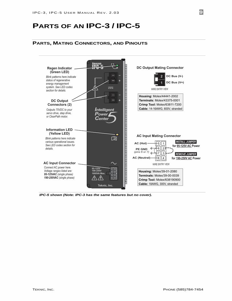
PARTS, MATING CONNECTORS, AND PINOUTS
AC Input Connector
Information LED(Yellow LED)
DC OutputConnectors (2)
Outputs 75VDC to your servo drive, step drive,or ClearPath motor.
Regen Indicator(Green LED)
Housing: Molex/44441-2002Terminals: Molex/43375-0001Crimp Tool: Molex/63811-7200Cable: 14-16AWG, 600V, stranded
WIRE ENTRY VIEW
DC Bus (V+)
DC Bus (V-)
1
2
DC Output Mating Connector
Housing: Molex/39-01-2080Terminals: Molex/39-00-0039Crimp Tool: Molex/638190900Cable: 18AWG, 300V, stranded
WIRE ENTRY VIEW
5 1
6 2
7 3
8 4
AC Input Mating Connector
PE GND(pins 6 or 7)
AC (Hot)
AC (Neutral)
Blink patterns here indicate status of regenerative energy management system. See LED codes section for details.
Blink patterns here indicate various operational issues. See LED codes section for details.
Connect AC power here. Voltage ranges listed are:95-125VAC (single phase)190-250VAC (single phase)
INSTALL JUMPER for 95-125V AC Power
REMOVE JUMPER for 190-250V AC Power
IPC-5 shown (Note: IPC-3 has the same features but no cover).
I P C - 3 , I P C- 5 U S E R M A N U A L R E V . 2 . 0 3 10
TEKNIC, INC. PHONE (585)784-7454
IPC USE INSTRUCTIONS
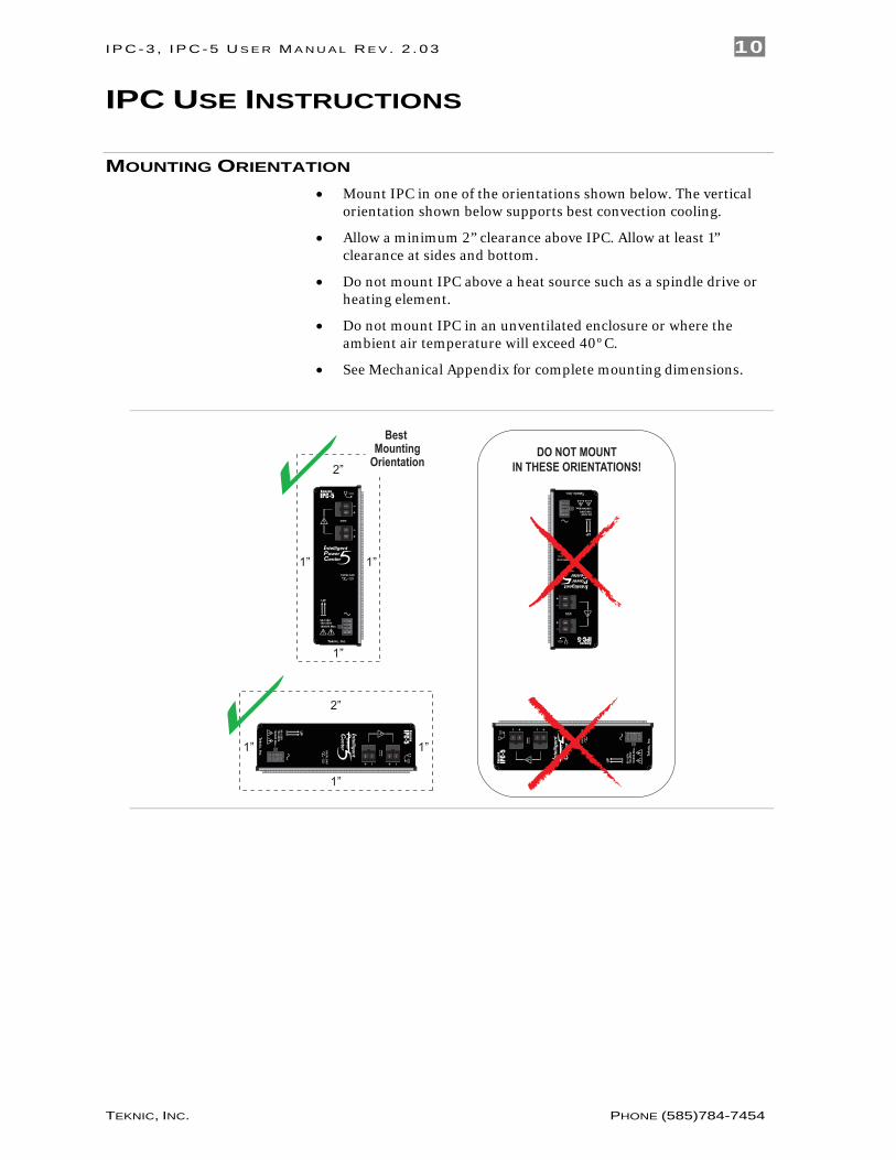
MOUNTING ORIENTATION • Mount IPC in one of the orientations shown below. The vertical
orientation shown below supports best convection cooling.
• Allow a minimum 2” clearance above IPC. Allow at least 1” clearance at sides and bottom.
• Do not mount IPC above a heat source such as a spindle drive or heating element.
• Do not mount IPC in an unventilated enclosure or where the ambient air temperature will exceed 40ºC.
• See Mechanical Appendix for complete mounting dimensions.
2”
1”
1”
1”
Best Mounting
Orientation
2”
1”
1”
1”
DO NOT MOUNT
IN THESE ORIENTATIONS!
I P C - 3 , I P C- 5 U S E R M A N U A L R E V . 2 . 0 3 11
TEKNIC, INC. PHONE (585)784-7454
HOW TO CONNECT IPC TO A LOAD • Remove AC power from supply.
• Connect DC power cable from supply to the load (typically a servo drive or ClearPath motor).
• Apply AC power to supply.
HOW TO DISCONNECT IPC FROM A LOAD • Remove AC power from supply.
• Disconnect DC power cable from the load.
ADDITIONAL USE NOTES • IPC-3/5 supplies are not designed to operate in series or parallel
configurations. Do not wire these power supplies together in any configuration.
• Always use the recommended wire gauge (or larger) for all cables connected to an IPC power supply.
I P C - 3 , I P C- 5 U S E R M A N U A L R E V . 2 . 0 3 12
TEKNIC, INC. PHONE (585)784-7454
CABLES
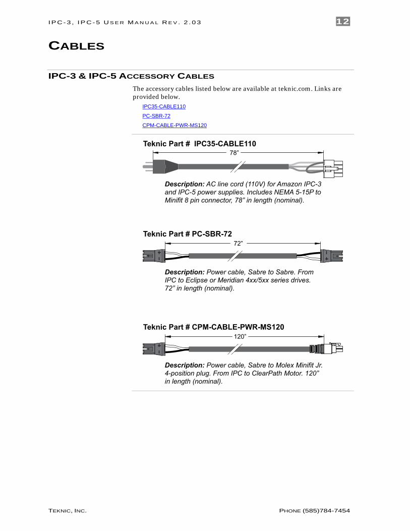
IPC-3 & IPC-5 ACCESSORY CABLES The accessory cables listed below are available at teknic.com. Links are provided below.
IPC35-CABLE110
PC-SBR-72
CPM-CABLE-PWR-MS120
78”Teknic Part # IPC35-CABLE110
Description: Power cable, Sabre to Sabre. From IPC to Eclipse or Meridian 4xx/5xx series drives.72” in length (nominal).
72”Teknic Part # PC-SBR-72
Description: Power cable, Sabre to Molex Minifit Jr. 4-position plug. From IPC to ClearPath Motor. 120”in length (nominal).
120”Teknic Part # CPM-CABLE-PWR-MS120
Description: AC line cord (110V) for Amazon IPC-3and IPC-5 power supplies. Includes NEMA 5-15P to Minifit 8 pin connector, 78” in length (nominal).
I P C - 3 , I P C- 5 U S E R M A N U A L R E V . 2 . 0 3 13
TEKNIC, INC. PHONE (585)784-7454
APPENDIX A: LED CODES
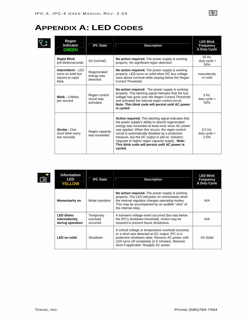
Regen Indicator GREEN
IPC State Description LED Blink Frequency
& Duty Cycle
Rapid Blink (16 blinks/second) On (normal) No action required. The power supply is working
properly. No significant regen detected. 16 Hz.
duty cycle = 50%
Intermittent - LED turns on solid but returns to rapid blink.
Regenerated energy was detected.
No action required. The power supply is working properly. LED turns on solid when DC bus voltage rises above nominal while staying below the Regen Control Threshold.
Intermittently on solid
Blink - 3 blinks per second
Regen control circuit was activated.
No action required. The power supply is working properly. This latching signal indicates that the bus voltage has gone over the Regen Control Threshold and activated the internal regen control circuit. Note: This blink code will persist until AC power is cycled.
3 Hz. duty cycle =
50%
Strobe - One short blink every two seconds
Regen capacity was exceeded.
Action required. This latching signal indicates that the power supply's ability to absorb regenerated energy was exceeded at least once since AC power was applied. When this occurs, the regen control circuit is automatically disabled as a protective measure, but the DC output is still on. Solution: Upgrade to higher regen capacity supply. Note: This blink code will persist until AC power is cycled.
0.5 Hz. duty cycle =
2.5%
Information LED
YELLOW IPC State Description
LED Blink Frequency
& Duty Cycle
Momentarily on Mode transition
No action required. The power supply is working properly. The LED will pulse on momentarily when the internal regulator changes operating modes. This may be accompanied by an audible "click" of the internal relay.
N/A
LED blinks intermittently during operation
Temporary overload occurred
A transient voltage event occurred (but was below the IPC's shutdown threshold). Action may be required to prevent future shutdowns.
N/A
LED on solid Shutdown
A critical voltage or temperature overload occurred, or a short was detected at DC output. IPC is in protective shutdown state. Remove AC power until LED turns off completely (2-5 minutes). Remove short if applicable. Reapply AC power.
On Solid
I P C - 3 , I P C- 5 U S E R M A N U A L R E V . 2 . 0 3 14
TEKNIC, INC. PHONE (585)784-7454
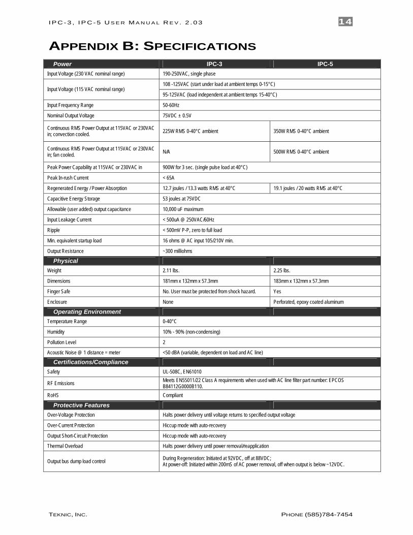
APPENDIX B: SPECIFICATIONS Power IPC-3 IPC-5
Input Voltage (230 VAC nominal range) 190-250VAC, single phase
108 -125VAC (start under load at ambient temps 0-15°C) Input Voltage (115 VAC nominal range)
95-125VAC (load independent at ambient temps 15-40°C)
Input Frequency Range 50-60Hz
Nominal Output Voltage 75VDC ± 0.5V
Continuous RMS Power Output at 115VAC or 230VAC in; convection cooled. 225W RMS 0-40°C ambient 350W RMS 0-40°C ambient
Continuous RMS Power Output at 115VAC or 230VAC in; fan cooled. N/A 500W RMS 0-40°C ambient
Peak Power Capability at 115VAC or 230VAC in 900W for 3 sec. (single pulse load at 40°C)
Peak In-rush Current < 65A
Regenerated Energy / Power Absorption 12.7 joules / 13.3 watts RMS at 40°C 19.1 joules / 20 watts RMS at 40°C
Capacitive Energy Storage 53 joules at 75VDC
Allowable (user added) output capacitance 10,000 uF maximum
Input Leakage Current < 500uA @ 250VAC/60Hz
Ripple < 500mV P-P, zero to full load
Min. equivalent startup load 16 ohms @ AC input 105/210V min.
Output Resistance ~300 milliohms
Physical Weight 2.11 lbs. 2.25 lbs.
Dimensions 181mm x 132mm x 57.3mm 183mm x 132mm x 57.3mm
Finger Safe No. User must be protected from shock hazard. Yes
Enclosure None Perforated, epoxy coated aluminum
Operating Environment Temperature Range 0-40°C
Humidity 10% - 90% (non-condensing)
Pollution Level 2
Acoustic Noise @ 1 distance = meter <50 dBA (variable, dependent on load and AC line)
Certifications/Compliance Safety UL-508C, EN61010
RF Emissions Meets EN55011/22 Class A requirements when used with AC line filter part number: EPCOS B84112G0000B110.
RoHS Compliant
Protective Features Over-Voltage Protection Halts power delivery until voltage returns to specified output voltage
Over-Current Protection Hiccup mode with auto-recovery
Output Short-Circuit Protection Hiccup mode with auto-recovery
Thermal Overload Halts power delivery until power removal/reapplication
Output bus dump load control During Regeneration: Initiated at 92VDC, off at 88VDC; At power-off: Initiated within 200mS of AC power removal, off when output is below ~12VDC.
I P C - 3 , I P C- 5 U S E R M A N U A L R E V . 2 . 0 3 15
TEKNIC, INC. PHONE (585)784-7454
APPENDIX C: MECHANICAL REFERENCE
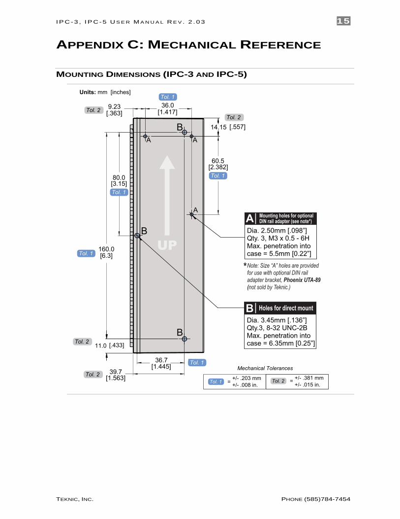
MOUNTING DIMENSIONS (IPC-3 AND IPC-5)
60.5
14.15
9.23 36.0
11.0
160.0 [6.3]
[1.417]
39.7 [1.563]
36.7 [1.445]
[2.382]
[.433]
[.557]
[.363]
80.0 [3.15]
B
B
A
A
A
B
Dia. 3.45mm [.136”]Qty.3, 8-32 UNC-2BMax. penetration into case = 6.35mm [0.25”]
B
*Note: Size “A” holes are provided for use with optional DIN rail adapter bracket, Phoenix UTA-89 (not sold by Teknic.)
UPDia. 2.50mm [.098”]Qty. 3, M3 x 0.5 - 6HMax. penetration into case = 5.5mm [0.22”]
A Mounting holes for optional DIN rail adapter (see note*)
Holes for direct mount
Tol. 1
Tol. 2Tol. 2
Tol. 1
Tol. 1
Tol. 1
Tol. 1
Tol. 1Units: mm [inches]
Tol. 2
Tol. 2
Mechanical Tolerances
= +/- .008 in.+/- .203 mm
Tol. 1 +/- .015 in.+/- .381 mm= Tol. 2
I P C - 3 , I P C- 5 U S E R M A N U A L R E V . 2 . 0 3 16
TEKNIC, INC. PHONE (585)784-7454
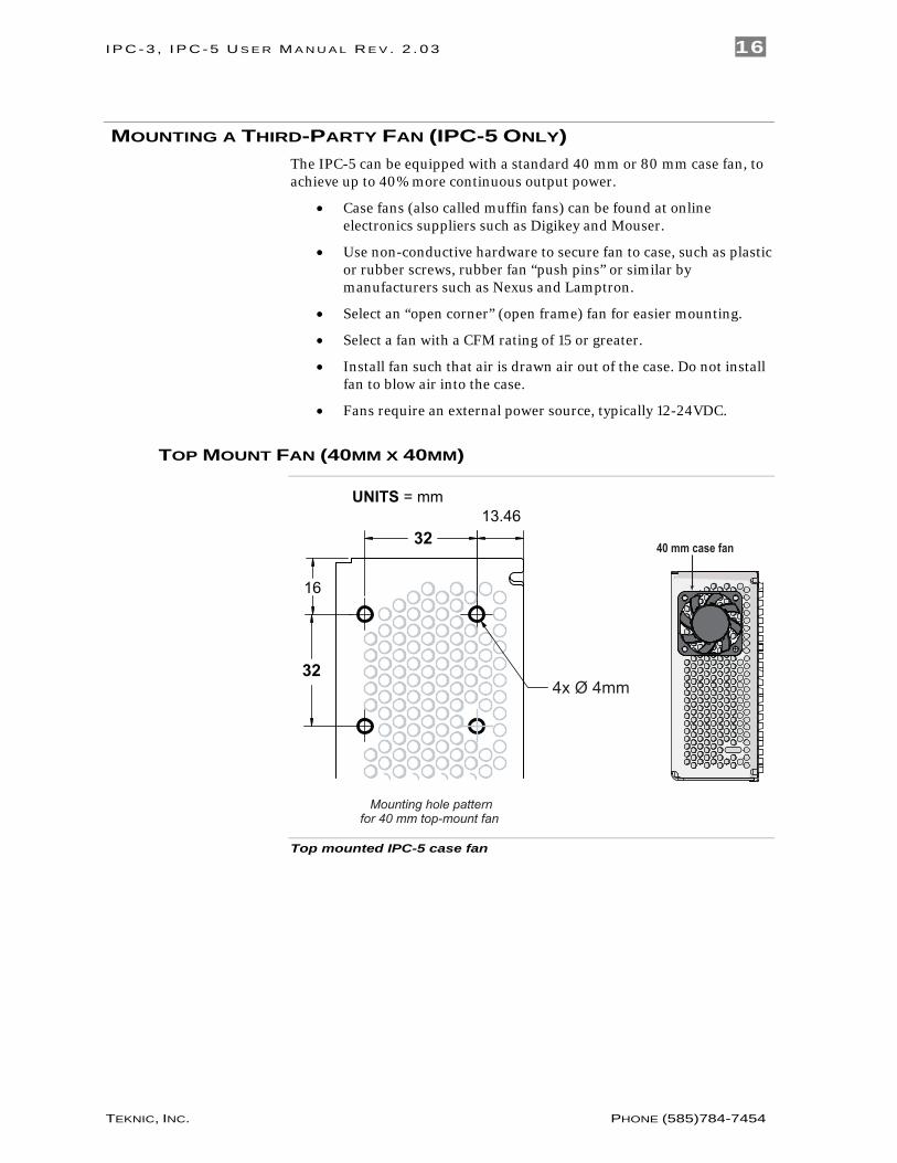
MOUNTING A THIRD-PARTY FAN (IPC-5 ONLY) The IPC-5 can be equipped with a standard 40 mm or 80 mm case fan, to achieve up to 40% more continuous output power.
• Case fans (also called muffin fans) can be found at online electronics suppliers such as Digikey and Mouser.
• Use non-conductive hardware to secure fan to case, such as plastic or rubber screws, rubber fan “push pins” or similar by manufacturers such as Nexus and Lamptron.
• Select an “open corner” (open frame) fan for easier mounting.
• Select a fan with a CFM rating of 15 or greater.
• Install fan such that air is drawn air out of the case. Do not install fan to blow air into the case.
• Fans require an external power source, typically 12-24VDC.
TOP MOUNT FAN (40MM X 40MM)
32 13.46
32
16
4x Ø 4mm
Mounting hole patternfor 40 mm top-mount fan
UNITS = mm
40 mm case fan
Top mounted IPC-5 case fan
I P C - 3 , I P C- 5 U S E R M A N U A L R E V . 2 . 0 3 17
TEKNIC, INC. PHONE (585)784-7454
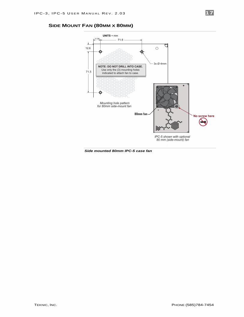
SIDE MOUNT FAN (80MM X 80MM)
12.6
11.94 71.5
71.5
3x Ø 4mm
Mounting hole patternfor 80mm side-mount fan
IPC-5 shown with optional 80 mm (side-mount) fan
80mm fan No screw here
NOTE: DO NOT DRILL INTO CASE. Use only the (3) mounting holes indicated to attach fan to case.
UNITS = mm
Side mounted 80mm IPC-5 case fan
I P C - 3 , I P C- 5 U S E R M A N U A L R E V . 2 . 0 3 18
TEKNIC, INC. PHONE (585)784-7454
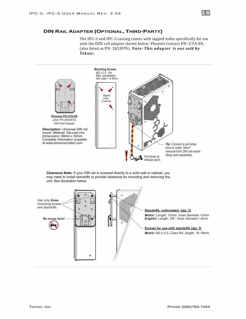
DIN RAIL ADAPTER (OPTIONAL, THIRD-PARTY) The IPC-3 and IPC-5 casting comes with tapped holes specifically for use with the DIN rail adapter shown below: Phoenix Contact PN: UTA-89, (also listed as PN: 2853970). Note: This adapter is not sold by Teknic.
Description: Universal DIN rail mount. Material: Die-cast zinc.Dimensions: 89mm x 52mm. Complete Information available at www.phoenixcontact.com.
Clearance Note: If your DIN rail is screwed directly to a solid wall or cabinet, you may need to install standoffs to provide clearance for mounting and removing the unit. See illustration below.
Use only three mounting screws and standoffs.
No screw here!
Standoffs, unthreaded (qty. 3)Metric: Length: 10mm. Inner diameter >3mmEnglish: Length: 3/8”. Inner diameter >3mm
Screws for use with standoffs (qty. 3)Metric: M3 x 0.5, Class 6H, length: 16-18mm
Phoenix PN UTA-89(also PN 2853970)DIN Rail Adapter
M3 x 0.5 - 6HMax. penetrationinto case = 5.5mm
Mounting Screws
Tappedholes
(3 places)
Tip: Connect a pull strap here to make “blind” removal from DIN rail easier. (SJFC)Strap sold separately.Pull down to
release latch.
AN
Nii
wAs H
eRe
I P C - 3 , I P C- 5 U S E R M A N U A L R E V . 2 . 0 3 19
TEKNIC, INC. PHONE (585)784-7454
APPENDIX D: MISCELLANEOUS TOPICS
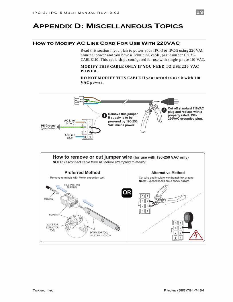
HOW TO MODIFY AC LINE CORD FOR USE WITH 220VAC Read this section if you plan to power your IPC-3 or IPC-5 using 220VAC nominal power and you have a Teknic AC cable, part number IPC35-CABLE110. This cable ships configured for use with single-phase 110 VAC.
MODIFY THIS CABLE ONLY IF YOU NEED TO USE 220 VAC POWER.
DO NOT MODIFY THIS CABLE If you intend to use it with 110 VAC power.
5 1
6 2
7 3
8 4
PE Ground (green/yellow)
AC Line (brown)
AC Line (blue)
Remove this jumperif supply is to be powered by 190-250VAC mains power.
1
OR5 1
6 2
7 3
8 4
5 1
6 2
7 3
8 4
How to remove or cut jumper wire (for use with 190-250 VAC only)NOTE: Disconnect cable from AC before attempting to modify.
TERMINAL
PULL WIRE ANDTERMINAL
SLOTS FOREXTRACTOR
TOOL
HOUSING
EXTRACTOR TOOLMOLEX PN: 11-03-0044
Remove terminals with Molex extraction tool. Cut wire and insulate with heatshrink or tape.Note: Exposed leads are a shock hazard.
Preferred Method Alternative Method
2 Cut off standard 110VAC plug and replace with a properly rated, 190-250VAC grounded plug.
I P C - 3 , I P C- 5 U S E R M A N U A L R E V . 2 . 0 3 20
TEKNIC, INC. PHONE (585)784-7454
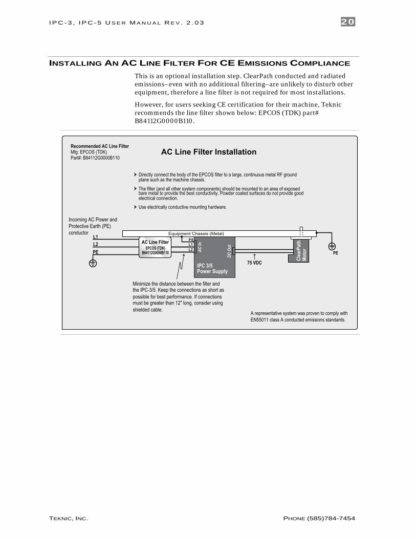
INSTALLING AN AC LINE FILTER FOR CE EMISSIONS COMPLIANCE This is an optional installation step. ClearPath conducted and radiated emissions–even with no additional filtering–are unlikely to disturb other equipment, therefore a line filter is not required for most installations.
However, for users seeking CE certification for their machine, Teknic recommends the line filter shown below: EPCOS (TDK) part# B84112G0000B110.
L1
L2
PE
Incoming AC Power andProtective Earth (PE)conductor
IPC 3/5Power Supply
Minimize the distance between the filter andthe IPC-3/5. Keep the connections as short aspossible for best performance. If connectionsmust be greater than 12" long, consider usingshielded cable.
AC Line Filter InstallationRecommended AC Line FilterMfg: EPCOS (TDK)Part#: B84112G0000B110
PE
75 VDC
A representative system was proven to comply withEN55011 class A conducted emissions standards.
L1
L2
P EAC Line Filter
AC In
DC O
utEPCOS (TDK)B84112G0000B110
Directly connect the body of the EPCOS filter to a large, continuous metal RF groundplane such as the machine chassis.
The filter (and all other system components) should be mounted to an area of exposedbare metal to provide the best conductivity. Powder coated surfaces do not provide goodelectrical connection.Use electrically conductive mounting hardware.
Equipment Chassis (Metal)
Cle
arP
ath
Mo
tor

I P C - 3 , I P C- 5 U S E R M A N U A L R E V . 2 . 0 3 21
TEKNIC, INC. PHONE (585)784-7454
Teknic, Incorporated 115 Victor Heights Pkwy Victor, NY 14564
© 2020 TEKNIC INCORPORATED, ALL RIGHTS RESERVED