Embed Size (px)
Citation preview

Distributed Computing (MCA-3) Tutorial No. 1
IPC MECHANISM
In computing, Inter process communication is a set of methods for the exchange of data among multiple threads in one or more processes. Process may be running on one or more computer connected by a network. IPC methods are divided into methods for message posting synchronization, shared memory and remote procedure calls (RPC). The method of IPC used may vary based on the bandwidth and latency of communication between threads, and the type of data being communicated.
There are several reasons for providing an environment that allows process co-operation
• Information Sharing • Speed up • Modularity • Convenience • Privilege Separation
Main IPC Method
Method Provided By FILE Most Operating System Signal Most Operating System, some operating System, such as window
implement signal only in the C-runtime library and provides no support for their use as in IPC method.
Socket Most Operating System Message Queue Most Operating System Pipe All POSIX System , Windows Named Pipe All POSIX System , Windows Semaphore All POSIX system, windows Shared Memory All POSIX System, windows Message Passing Used in MIP paradigm, java RMI, CORBA, MSMQ, mail slots, others. Memory mapped file
All POSIX system, windows, this method May carry race condition risk, if a temporary file is used.
Let Us discuss the important methods of IPC:
1. Signal
Signals are the oldest inter process communication used. It is a limited form of inter process communication used in UNIX and other Posix complaint operating systems.
Essentially it is an asynchronous notification sent to a process in order to notify it of an event that occurred. When a signal is sent to a process, the operating system interrupts the process’s normal flow of execution.
2. Socket:
The socket API comprises of a library for developing applications in C programming language that performs inter process communication.
Socket API important functions:
Distributed Computing (MCA-3) Tutorial No. 1
• Socket (): Creates anew socket of certain socket type. Identification by an integer number and allocates system resources to it.
• Bind (): associates a socket with a socket address structure.
• Listen () – Is used on a server side and causes a bound TCP socket to enter listening state.
• Connect () – To establish a new TCP connection.
3. Shared Memory:
A method of inter process communication is a way of exchanging data between programs running at the same time. One process will create an area in RAM which other process can access.
IPC by shared memory is used to transfer images between the application and the X server on the UNIX system, or inside the istream object returned by COMarshalInterThreadInterfaceStream in the COM libraries under windows.
4. Message Passing:
It is a form of communication used in parallel computing, object-oriented programming and inter process communications. In this model, processes or objects can send and receive messages comprising zero or more bytes, complex data structures or even segments of code to other processes. By waiting for messages, processes can also synchronize.
IPC IN DISTRIBUTED COMPUTING SYSTEM:
1. IN AMOEBA (Microkernel Based Distributed Operating System)
Basic IPC Mechanism:
It uses the client server model, for operation on the objects. Each client server id defined by a set of stub procedures that clients can call. When a stub procedure is called by a client it packs the parameter into a message.
And invokes the kernel primitives to actually send the message kernel provides the following 3 basic IPC primitives:
• Trans: used by a client to send a request message to server. • Get_request: is used by a server to announce to accept message. • Send_reply: is used by server to send a reply to a client. The basic IPC Mechanism of Amoeba is also referred to as RPC. It has following properties. • It supports only synchronous type of communication. • Messages are unbuffered hence message is simply discarded if its receiver is
not in ready state to receive it. • It supports at most once semantics.

Distributed Computing (MCA-3) Tutorial No. 1
• Stateless servers are used.
2. MACH (also a microkernel based operating system developed at Carnegie Mellon University)
The basic abstractions used for inter process communications in Mach are ports and messages.
• A “port” in Mach is a one way communication channel, logically a bounded message queue.
• A “Message” is a type collection of data objects, to communicate with another process.
MANAGEMENT OF PORTS:
Ports are managed and protected by Kernel. They are kept tract on a per process basis rather than per thread. A kernel keeps no record of which thread created which port.
Mach provides facility to group a number of ports into a port. A port may belong to atmost one port set at a time
• Message passing:
The basic inter process communication involves the sender process sending a message to a port and a receiver process receiving it from the same port. Message may be sent and received either synchronously or asynchronously.
• Network wide IPC:
Mach uses user level servers called network message server and network ports they are ports for receiving messages from other nodes of the system.
The three main jobs performed by network messages servers are as follows:
1. Making the network wide IPC mechanism network transparent. 2. Supporting heterogeneity by translating message Data from the senders computer
format to the receivers computer format 3. Performing authentication of the other network message servers to prevent message data
from falling into the hands of unauthorized user.

Distributed Computing (MCA-3) Tutorial No. 2
SUN RPC Sun RPC which was designed for client-server communication in the Sun NFS network file system. Sun RPC is sometimes called ONC (Open Network Computing) RPC. Sun RPC is supplied as a part of the various Sun UNIX operating systems and is also available with other NFS installations. Implementers have the choice of using remote procedure calls over either UDP/IP or TCP/IP. The Sun RPC system provides an interface language called XDR and an interface compiler called rpcgen which is intended for use with the C programming language. Interface definition language
The Sun XDR language which was originally designed for specifying external data representations was extended to become an interface definition language. It may be used to specify a Sun RPC interface which contains a program number and a version number rather than an interface name, together with procedure definitions and supporting type definitions. A procedure definition specifies a procedure signature and a procedure number. As only a single input parameter is allowed, procedures requiring multiple parameters must include them as components of a single structure. The output parameters of a procedure are returned via a single result. The procedure signature consists of the result type, the name of the procedure and the type of the input parameter. The type of both the result and the input parameter may specify either a single value or a structure containing several values.
For example, see the XDR definition in the following file example of an interface with a
pair of procedures for writing and reading files. The program number is 9999 and the version number is 2. The READ procedure takes as input parameter a structure with three components specifying: a file identifier, a position in the file and the number of bytes required. Its result is a structure containing the number of bytes returned and the file data. The WRITE procedure has no result. The WRITE and READ procedures are given numbers 1 and 2. The number zero is reserved for a null procedure that is generated automatically and is intended to be used to test whether a server is available.
The interface definition language provides a notation for defining constants, typedefs,
structures, enumerated types, unions and programs. Typedefs, structures and enumerated types have the same syntax as in C. The interface compiler rpcgen can be used to generate the following from an interface definition:
• Client stub procedures; • Server main procedure, dispatcher and server stub procedures. The dispatcher can pass
authentication information (user id and group id) to the server procedures; • XDR marshalling and unmarshalling procedures for use by the dispatcher and client and
server stub procedures; • a header file, for example "FileReadWrite.h", containing definitions of common
constants and types that may be used in client and server programs. The service procedure signatures are given as C function prototypes. The developer of the service provides implementations of these procedures that conform to the prototypes.

Distributed Computing (MCA-3) Tutorial No. 2
Files interface in Sun XDR. /* * FileReadWrite service interface definition in file FileReadWrite.x */ const MAX = 1000; typedef int FileIdentifier; typedef int FilePointer; typedef int Length; struct Data { int length; char buffer[MAX]; }; struct writeargs { FileIdentifier f; FilePointer position; Data data; }; struct readargs { FileIdentifier f; FilePointer position; Length length; }; program FILEREADWRITE { version VERSION { void WRITE(writeargs)=1; Data READ(readargs)=2; }=2; } = 9999;
Client program
A client program imports the appropriate service interface and calls the remote procedures, for example, READ and WRITE. It is supported by the client stub procedures and the marshalling and unmarshalling procedures generated by the interface compiler rpcgen.
Sun RPC does not have a network-wide binding service. Instead it provides a local
binding service called the port mapper which runs on every computer. Each instance of a port mapper records the port in use by each service running locally. Therefore to import an interface, the client must specify the hostname of the server as well as the program number and version number. In the following code, the procedure clnt_create is used for this purpose. It returns a client ‘handle’ to use when remote procedures are called. The client handle contains the necessary information for communicating with the server port, such as the socket descriptor and socket address.

Distributed Computing (MCA-3) Tutorial No. 2
clnt_createclientHandle
Gets a client handle. The arguments give the hostname of the server and the program and version numbers specified in the interface definition. The last argument specifies whether UDP or TCP should be used.
Several variants of clnt_create are available. These provide more control for the programmer such as specifying the service port. When UDP is used the time-out value between retries may be specified. When TCP is used the send and receive buffer sizes may be specified. The remote server procedures are called in normal C language procedure call notation. The remote calls are made indirectly via calls to the client stub procedures. Remote procedures are called in the same way as local procedures with two arguments. The input arguments must be packed into a single structure which is passed as the first argument and the ‘handle’ returned by clnt_create is passed as the second argument. The return value may be a structure containing several results. The client stub procedure name is the name given in the interface definition, converted to lower case and with an underscore and the version number appended, for example, READ is converted to read_2.
Client stubs
Each client stub procedure calls the procedure clnt_call which makes an RPC call to a server. The arguments specify: a client handle, a procedure identifier, the input arguments and a procedure to marshal them, a reference to a variable in which to store the output arguments, a procedure to unmarshal them and the total time in seconds to wait for a reply after several retries.
Clnt_call uses at-least-once call semantics. The time-out between retries has a default
value which can be set when the ‘handle’ is obtained. The number of retries is the total time to wait divided by the time-out between retries. After it sends a request message, it waits for a time-out period and if there is no reply, tries again several times. Eventually if it gets no answer, it returns an error value. If an RPC is successful it returns zero. The input arguments and the procedure to marshal them are each given in a single argument to clnt_call . If there are several input arguments, they must be grouped together into a structure and the marshalling procedure must be designed to flatten the entire structure. If several results are returned by the server, they will be unmarshalled and stored in a single structure. When Sun RPC is used with UDP, the length of request and reply messages is restricted in length - theoretically to 64 kilobytes, but more often in practice to 8 or 9 kilobytes
C program for client in Sun RPC.
/* File : C.c - Simple client of the FileReadWrite service. */ #include <stdio.h> #include <rpc/rpc.h> #include "FileReadWrite .h" main(int argc, char ** argv) { CLIENT *clientHandle; char *serverName = "coffee";

Distributed Computing (MCA-3) Tutorial No. 2
readargs a; Data *data; clientHandle= clnt_create(serverName, FILEREADWRITE,VERSION, "udp");
/* creates socket and a client handle*/ if (clientHandle==NULL){ clnt_pcreateerror(serverName); /* unable to contact server */ exit(1); } a.f = 10; a.position = 100; a.length = 1000; data = read_2(&a, clientHandle);/* call to remote read procedure */ ••• clnt_destroy(clientHandle); /* closes socket */ }
Server program
The implementor uses the C function prototypes in the header file created by rpcgen as a basis for the implementation of the service as shown in the following piece of code. The server procedure names are the names given in the interface definition converted to lower case and with an underscore and the version number appended. The argument of each server procedure is a pointer to a single argument or to a structure containing all the arguments. Similarly the value returned is a pointer to a single result or to a structure that contains the results. The latter must be declared as static.
The server program consists of the server procedures, supported by the main, the
dispatcher and the marshalling procedures, all of which are output by rpcgen. The main procedure of a server program creates a socket for receiving client request messages and then exports the service interface by informing the local port mapper of the program number, version number and the port identifier of the server.
When a server receives an RPC request message, the dispatcher checks the program and
version numbers, unmarshals the arguments and then calls the server procedure corresponding to the procedure number specified in the RPC request message. When the server procedure returns the results, it marshals them and transmits the reply message to the client.
C program for server procedures in Sun RPC.
/* File S.c - server procedures for the FileReadWrite service */ #include <stdio.h> #include <rpc/rpc.h> #include"FileReadWrite.h" void * write_2(writeargs *a) {

Distributed Computing (MCA-3) Tutorial No. 2
/* do the writing to the file */ } Data * read_2(readargs * a) { static Data result; /* must be static */ result.buffer = ... /* do the reading from the file */ result.length = ... /* amount read from the file */ return &result; }
Binding
We have already noted that Sun RPC operates without a network-wide binding service. Therefore clients must specify the hostname of the server when they import a service interface. The port mapper enables clients to locate the port number part of the socket address used by a particular server. This is a local binding service – it runs at a well-known port number on every host and is used to record the mapping from program number and version number to port number of the services running on that host. When a server starts up it registers its program number, version number and port number with the local port mapper. When a client starts up, it finds out the server’s port by making a remote request to the port mapper at the server’s host, specifying the program number and version number. This means that servers need not run at well-known ports.
When a service has multiple instances running on different computers, the instances may
use different port numbers for receiving client requests. Recall that broadcast datagrams are sent to the same port number on every computer and can be received by processes via that port number. If a client needs to multicast a request to all the instances of a service that are using different port numbers, it cannot use a direct broadcast message for this purpose. The solution is that clients make multicast remote procedure calls by broadcasting them to all the port mappers, specifying the program and version number. Each port mapper forwards all such calls to the appropriate local service program, if there is one. Marshalling
Sun RPC can pass arbitrary data structures as arguments and results. They are converted to External Data Representation (XDR). The marshalling and unmarshalling procedures specified in clnt_call may be built-in procedures supplied in a library or user-defined procedures defined in terms of the built-in procedures. The library procedures marshal integers of all sizes, characters, strings, reals and enumerated types. Lower-level facilities

Distributed Computing (MCA-3) Tutorial No. 2
The RPC facilities described above supply a set of defaults which are adequate for most purposes. The lower-level facilities provide additional control for the programmer who needs it. The main lower-level facilities are the following:
• Tools for testing the implementation and running of services, such as null RPC calls, to test whether a server is running, checks for invalid procedure identifiers and pseudo RPC calls allowing client and server to be tested within a single process;
• Management of dynamic memory allocation in marshalling procedures (which is not provided by the built-in XDR procedures);
• Broadcast RPC. A client program may make an RPC to all instances of a service. This call is directed to the port mapper at all computers in the local network which passes it on to the local service registered with the given program name. The client picks up any replies one by one;
• Batching of client calls that require no reply. The RPC calls can be buffered and then sent in a pipeline to the server over TCP/IP;
• Call-back by the server to a client. This allows the client to become a server temporarily and to pass in an RPC call the information about its service;
• Authentication: Sun RPC includes a mechanism allowing clients to pass authentication parameters that can be checked by the server. The default is that this mechanism does not operate. The client program may select a UNIX or a DES style of authentication. In the UNIX style, the uid and gid of the user running the client program are passed in every request message. The authentication information is made available to the server procedures via a second argument. The server program is responsible for enforcing access control by deciding whether to execute each procedure call according to the authentication information. DES authentication is secure in comparison with UNIX authentication.

Distributed Computing (MCA-3) Tutorial No. 3
TUTORIAL 3-WHITE BOARD APPLICATION
Introduction
Whiteboard is an application that provides its user an area to post messages and other objects for sharing with other users and also to receive other users' posts in near real time. When a user posts an object, all other users in the same session see it. The basic tool is a text tool, with which text messages are posted. Drawing tool is also very common, where one drawing is shared by all other users, and multiple user can work on the same drawing. More advanced tools will give users the ability to post images, and even audio and video clips, to the whiteboard. The delay between posting and receiving should be small, but the variance is not critical, except when audio and video are used and are streamed from the source
Background
Most whiteboard implementations fall into two categories: 1. Server based 2. Non server based.
1. Server based Whiteboard Implementations
In server based whiteboard, all users log on to a server. Data exchanges are all between the server and individual clients.
The server maintains the states of the session as well as the states of each client. Each client posts messages and drawings to the server, and the server forwards the messages to each client in the session.
Clients could also obtain session information, e.g. participants list, from the server.
2. Non Server based Whiteboard Implementations
In a non server based whiteboard, all clients communicate to each other. This is often done through broadcast or multicast.
In the case of multicast, each client who wish participate in a session should explicitly join the session (in multicast, a session is represented by a multicast IP address and a port number).
Clients send messages on this IP multicast address and the port number. The messages will be forwarded to every client who has joined the session.
There is no central control point, so each client should main its own states and the states of the session.

Distributed Computing (MCA-3) Tutorial No. 3
Advantages of Non-server based Whiteboard Implementation
Non server based whiteboard avoids the problem that server based whiteboard has, that is, the server is a single point of failure. When the server fails, no session could take place. This implementation also has better scalability, because it does not depend on the processing power of the server. On the other hand, because there is no single session control point, the control of the session is distributed among all participants, and this is usually more complicated than centrally controlled implementations. Java is used for implementing this whiteboard application. Java is a platform independent programming language and computing platform. It is available for most major hardware/OS platforms. Java programs require little or no effort to port from one platform to another. Using Java to implement the whiteboard simplifies the task of cross platform communications. JDK1.1.4 is used in the development. It provides support for IP multicast within its core API.
RTP is a protocol designed for real-time applications over internet, RTCP (Ream-time Transport Control Protocol) is the accompanying protocol which specifies how the control is carried out in a session. In this implementation, RTCP is used to carry session information such as participant names and email addresses. RTP/RTCP are designed for real time applications, it specifies comprehensive timestamps to facilitate accurate playback and intra-media synchronization. These features are not needed in whiteboard (no streaming in this implementation), and are not implemented. And due to time constraint, only a chat tool is implemented. Please refer to Future Work in Program Documentation for discussion on future improvement.
Design and Architecture
The whiteboard is implemented as a Java application instead of a Java applet. This is due to the security restriction on applet that it can only make network connections to the host where it comes from.
The whiteboard application accomplishes the following tasks:
• At the beginning of session, it interacts with user to obtain information about the user: name, email address; information about the session: multicast IP address and port.
• With above information the application joins the multicast group. It accepts user inputs, put them in network packets and sends them, and receives packets from network, take out user messages and post it to the user.
• The whiteboard maintains a list of participants of the current session. This list is updated periodically. New participants' information is added to the list when they join, and when they leave, other participants are notified.
RTP and RTCP are used in my implementation. User messages are encapsulated in RTP packets. Session control information is encapsulated in RTCP packets. These packets are
Distributed Computing (MCA-3) Tutorial No. 3
in turn put in IP packets and sent out using multicast. Pair of port numbers is needed. One for RTP transmission, the other for RTCP transmission. At the beginning of a session, user enters an IP address and a port number. This port number is for RTP. RTCP port number is simply the RTP port plus 1, and the two share the same IP address.
The whiteboard has three major components in its main window. A text area for displaying user messages (including those sent by itself), a text area for displaying participant list (in the format of user@host), and a text field for user to type in messages.
The whiteboard is implemented as a multi-threaded application. At start, the application initializes a dialog box with four entries for the user to fill in: User Name, Email Address, Session IP Address and Port Number. After the user fills in these items, the application (main thread) initializes a multicast socket for user message transmission. It then spawns a thread called RTPReceiver. This thread takes in the IP address, joins the multicast group and listens on the designated port. When a message is received, it extracts the message from the packet, and posts it in the user message area in the main window. The thread blocks when there is no message.
The main thread takes care of the transmission of user messages. A class RTPSender is created for this purpose. An instance of this class is created after the user provides necessary information. This instance is registered as a key event listener of the user message input text field. Each time a key is pressed in this field, the keyPressed method of this instance is called. And if the key pressed is the Enter key, the text in the field is extracted, encapsulated in a RTP packet, and sent out.
The main thread spawns another thread after it starts the RTPReceiver thread. This thread is the RTCPHandler thread. This thread keeps track of the session control information. It takes the IP address and port number passed from main thread, and spawns yet another thread, RTCPReceiver, for receiving RTCP packets. Sending is handled in the thread itself.
RTCPHandler maintains a vector which contains the participant information. This vector is updated by the RTCPReceiver thread after each RTCP packet is received. If the RTCP packet contains information about user whose information does not exist in the vector yet, it is added into the vector, and participant information text area is updated. If some user leaves the session (a BYE packet is received), the thread removes the corresponding information contained in the vector, and notifies the user in the participant list area that some user has left, together with the user's information.
RTCP packet is sent periodically to keep other user notified the existence of this user. The packet is either SR or RR compounded with SDES packet. Within SDES packet, CNAME, NAME and EMAIL fields are present. In the RTP and RTCP headers, there are several timestamp fields--RTP timestamp, NTP timestamps. The whiteboard does not need accurate rendering, so these timestamps are not used and are all set to 0 in the headers.

Distributed Computing (MCA-3) Tutorial No. 3
Figure: Software Architecture.
When a user joins a session, it picks a number, Synchronized Source (SSRC) as its id. This number is 32 bits long and should be unique within a session. In this application, it
Distributed Computing (MCA-3) Tutorial No. 3
is generated by the Java random number generator (Java.util.Random) using the current machine time as the seed. Collisions are possible if many users start at about the same time. But for a small session, the probability is very small, and is not considered in this implementation.
Another randomly generated number is the starting sequence number. This is a 16 bit number again generated by the Java random number generator. The generator generates signed numbers, so the sequence number and SSRC id can be negative, but this does not violate the specification of the RTP protocol.
Multi-User Whiteboard (Network Application)
Multi-user whiteboard is a java based swing application, by which you can share drawing across multiple online users. Currently it is supporting limited shapes to be drawn. But in future it can be extended many more with little effort because all the networking and I/O stuff are handled in a nice way. To support a new shape in whiteboard one can do it with a very little change at coding level.
It has two modules:
• Client module
• Server module
It can be deployed as standalone desktop client application or in a web application using jnlp or applet.
Technology used:
• Java Network Programming (socket)
• Java Swing and Applet
• Mysql Database
Distributed Computing (MCA-3) Tutorial No. 4
TUTORIAL 4
Q.1 Case study on DTS
Ans:
Stands for Distributed Time Service
Goals:
Maintaining Time Transparency Keeping all clocks throughout distributed system mutually consistent, to within an
acceptable accuracy (for timed events, comparisons, etc) Keeping the clocks in touch with reality, external trusted source
Challenges:
Synchronizing time across all distributed computers Compensating for unequal drift rates between synchronizations
DTS Components:
Global Time Servers The distributed system has multiple Global Time Servers throughout. Global Servers
keep Local Time Servers in different cells synchronized Local Time Servers. Each local cell has a Local Time Server that keeps track of its local time
Requests synchronizations from Global Time Servers
Definition of key terms:
Clock drift rate:
Measure of the rate of increase of inaccuracy in the local clock time
Universal Coordinated Time (UCT):
A universally (worldwide) accepted form of time, expressed as the elapsed time since October 15, 1582, the beginning of the Gregorian calendar. Worldwide UCT servers provide the UCT time service (via satellite, radio, or telephone connection)
How DTS works:
Local Time Server knows limits of hardware clock (clock drift rate) LTS keeps track of inaccuracy that builds over time LTS requests synchronization from Global Time Servers (GTS) after reaching an
established inaccuracy threshold

Distributed Computing (MCA-3) Tutorial No. 4
All GTS responses include the corresponding inaccuracies, thereby representing time as a probable range, not a finite value
LTS calculates a probable correct time based on the multiple time responses that were received
Local time adjustments can be made either abruptly or gradually At least one Global Time Server is configured to synchronize time with outside Universal
Coordinated Time (UCT) source Max range of time overlap from all sources is computed Data outside of range is rejected as untrustworthy Midpoint of range is computed as accurate time
DTS Library Procedures (calls):
There are 33 total calls supported by DTS
There are 6 groups of time-related calls, calls for:
Retrieving times – Get the current time Converting times – Binary-ASCII conversion Manipulating times – Interval arithmetic Comparing times – Compare two times Calculating times - Arithmetic operations on times Using time zones – Time zone management
The DCE Distributed Time Service (DTS) provides synchronized time on the computers participating in a distributed computing environment. In a single system, one clock provides the time to all applications. In a distributed system, however, each node has its own clock. Even if all the clocks in a distributed system could be set to one consistent time at some point, they would drift away from that time at different rates. As a result, different nodes would have different times. This is a problem for distributed applications where the ordering of events is important. DTS enables distributed applications to determine event sequencing, duration, and scheduling. DTS synchronizes a DCE host's time with Universal Coordinated Time (UTC), an international time standard.

Distributed Computing (MCA-3) Tutorial No. 4
Q.2 Explain why one time synchronization of clock of all nodes of distributed system is not sufficient and why periodic resynchronization is necessary? How will you determine the interval for periodic synchronization?
Ans:
A Clock always runs at constant rate because its quartz crystal oscillates at a well defined frequency. However due to the difference in the crystals the route at which 2 clocks was normally different from each other.
The difference in oscillation period between 2 clocks might be extremely small, but the difference accumulated over a many oscillations leads to an observable difference in the times of 2 clocks no matter how accurately then is initiated to same value.
Therefore if we use one time synchronization of all clocks of all the other nods then with passage of time a computer clock benefits from real time clock used for initial setting.
Hence a computer clock must be periodically resynchronized with real time clock to keeps non fault.
More precisely, let us suppose that when the real time is t, the time value of a clock p is Cp(t).If all clocks in the world are perfectly synchronized ,we would have Cp(t)=t for all p and all t. That is ,if C denotes the time value of a clock in the ideal case all dt should be 1.Therefore,if the maximum drift rate allowable is p,a clock is said to be no-fault if the following condition holds for it
1-p<=dc/dt<=1+p
Slow clock region
Dc/dt<1
Dc/dt=1
Clock time
Real time
Fast clock region
Dc/dt>1
Distributed Computing (MCA-3) Tutorial No. 4
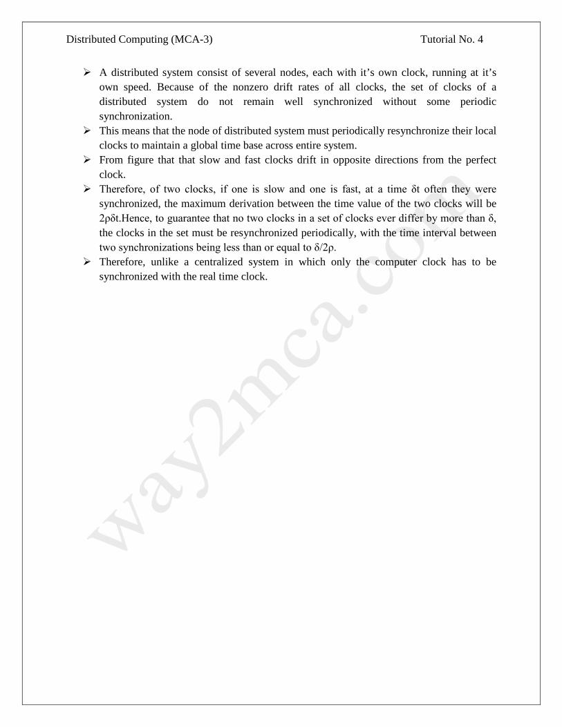
A distributed system consist of several nodes, each with it’s own clock, running at it’s own speed. Because of the nonzero drift rates of all clocks, the set of clocks of a distributed system do not remain well synchronized without some periodic synchronization.
This means that the node of distributed system must periodically resynchronize their local clocks to maintain a global time base across entire system.
From figure that that slow and fast clocks drift in opposite directions from the perfect clock.
Therefore, of two clocks, if one is slow and one is fast, at a time δt often they were synchronized, the maximum derivation between the time value of the two clocks will be 2ρδt.Hence, to guarantee that no two clocks in a set of clocks ever differ by more than δ, the clocks in the set must be resynchronized periodically, with the time interval between two synchronizations being less than or equal to δ/2ρ.
Therefore, unlike a centralized system in which only the computer clock has to be synchronized with the real time clock.

Distributed Computing (MCA-3) Tutorial No. 6
Tutorial 6 Case Study on Mach Mach is an operating system kernel developed at Carnegie Mellon University to support operating system research, primarily distributed and parallel computation. It is:
• Additional middle layer of operating system • Other O/S’s typically implemented as user level O/S’s
Overall Mach Structure
Mach microkernel
application level O/S (e.g., UNIX)
User application
Distributed Computing (MCA-3) Tutorial No. 6
Goals of Mach
• Simple kernel – Only one way to accomplish kernel programming tasks
• Diverse hardware support – “Multiprocessing”: Tightly coupled or loosely – Varying degrees of shared memory access – One to thousands of processors – Heterogeneous system support
• Distributed & object-oriented – All kernel objects within the system are location independent
• Integrated memory management & interprocess communication (IPC) • Varying network speeds • Extensible microkernel
Interprocess Communication • Ports
– Microkernel protected communication channel – Communication occurs by sending messages to ports – Microkernel object reference mechanism – Provides access to devices, tasks, threads, memory objects, and processors – Allow microkernel objects to transparently reside anywhere in network – Threads have port rights (send & receive)
• Port sets – Group of ports sharing a common message queue – By receiving messages for a port set, a thread can service multiple ports – Similar to select call in BSD Unix
Mach Ports
• Communication channels & object reference mechanism – Methods on kernel objects invoked via messages – Enable a thread to send data to another thread in a controlled manner
• Kernel protected; implemented as a bounded queue – Send & receive rights
• Only one task with receive rights • Can be multiple with send rights • Sending receive rights to another task causes ownership of receive
rights to change • Ports are location independent
– Sending a message to port will result in the receiver task getting the message
• Independent of where receiver is on network, – Tasks & corresponding ports can be migrated to another computer
• With same machine architecture

Distributed Computing (MCA-3) Tutorial No. 6
Mach Messages • Messages
– Typed collection of data objects • Used to implement remote procedure calls (RPC) • Port rights sent using messages • Data in messages: typed • Simple types (integer, float etc) • In-line and out-of-line data • Out-of-line data: Pointers
– Kernel interprets these pointers as part of message passing – Receiver on same computer
• Don’t want to necessarily copy message from sender to receiver – Takes time to copy messages
• Instead, when message contents unchanged, use virtual memory-based technique for improving efficiency
– A kind of shared memory solution – “copy-on-write”
– Receiver on different computer • Need to copy data referred to by pointer
Mach CPU Scheduling
• Global & local (single CPU) run queues – Thread assigned to processor from a run queue – Only threads are scheduled; compete equally for CPU
• Threads have dynamic priorities 0-127 – Generally equal competition for resources – Priority based on exponential average of CPU usage
• Reduces priority with increasing CPU usage • Threads can be “bound” to a CPU
– Thread will only run on that CPU – E.g., for a thread that handles a device associated with that CPU
• Variable time quantum (processor time per process) – Dependent on # processors & # processes
Tasks and Threads
• New tasks inherit duplicate of parent memory • New tasks have several ports
– E.g., task self-- represents the task in calls to the microkernel (similar to a task name)
• Tasks are composed of multiple threads – I.e., programs can be designed with multiple threads of execution
• Task’s threads may be executing on multiple processors – Increases efficiency of user-level programs – E.g., only a thread doing a system call is blocked, not entire task

Distributed Computing (MCA-3) Tutorial No. 6
Case study on CHORUS. • A CHORUS System is composed of a small-sized Nucleus and a number of
System Servers. Those servers cooperate in the context of Subsystems (e.g., UNIX) providing a coherent set of services and interfaces to their "users" (Figure l).
• Its overall organization is a logical view of an open operating system. It can be mapped on a centralized as well as on a distributed configuration. At this level, distribution is hidden.
• The choice has been to build a two level logical structure, with a "generic nucleus" at the lowest level, and almost autonomous "subsystems" providing applications with usual operating system services.
• Therefore the Chorus Nucleus has not been built as the core of a specific operating system (e.g., UNIX), rather it provides generic tools designed to support a variety of host subsystems, which can co-exist on top of the Nucleus.
• This structure allows support of application programs which already run on existing (usually centralized) operating systems, by reproducing those existing operating system interfaces within a given subsystem. This approach is illustrated with UNIX in this paper.
• Note also the now classic idea of separating the functions of an operating system into groups of services provided by autonomous servers inside subsystems. In monolithic systems, these functions are usually part of the "kernel."
• This separation of functions increases modularity and therefore portability and scalability of the overall system.
Chorus Architecture
Distributed Computing (MCA-3) Tutorial No. 6
Chorus nucleus
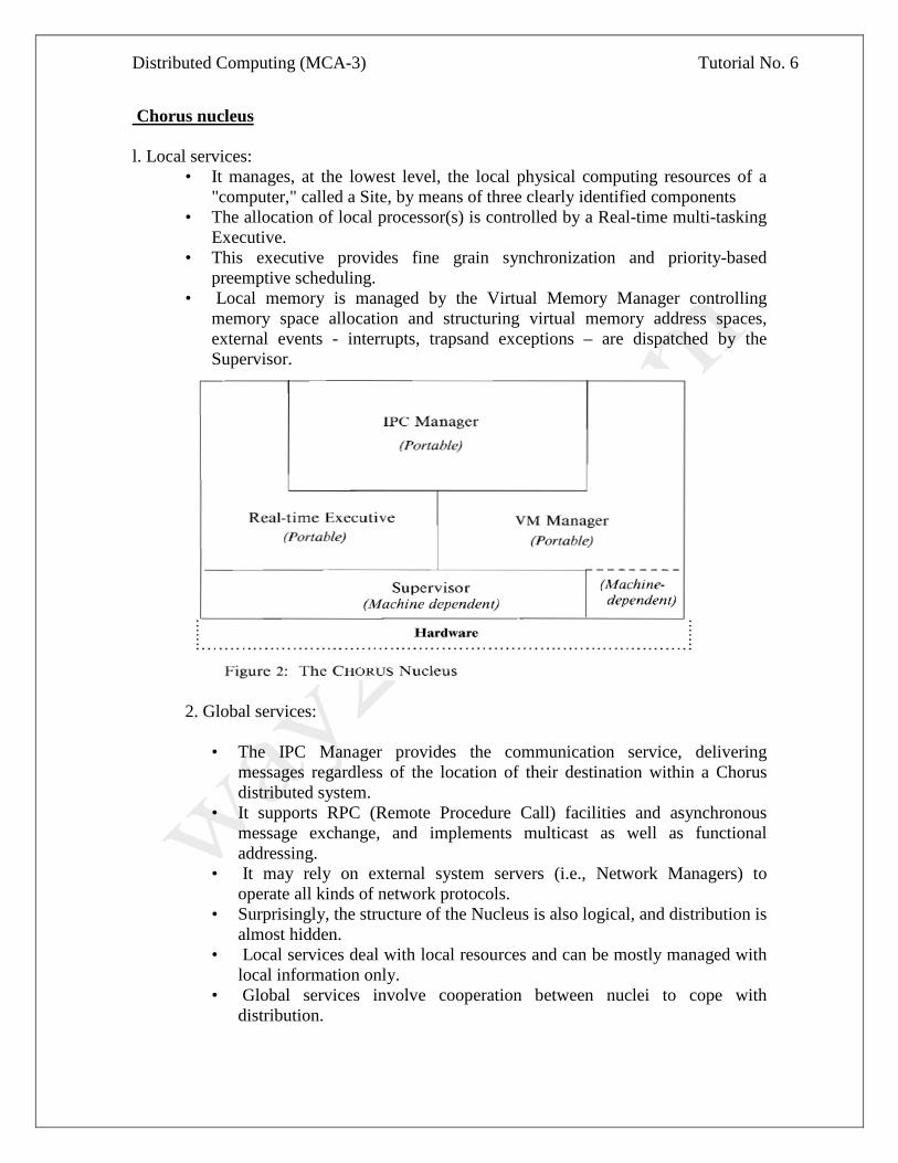
l. Local services: • It manages, at the lowest level, the local physical computing resources of a
"computer," called a Site, by means of three clearly identified components • The allocation of local processor(s) is controlled by a Real-time multi-tasking
Executive. • This executive provides fine grain synchronization and priority-based
preemptive scheduling. • Local memory is managed by the Virtual Memory Manager controlling
memory space allocation and structuring virtual memory address spaces, external events - interrupts, trapsand exceptions – are dispatched by the Supervisor.
2. Global services:
• The IPC Manager provides the communication service, delivering
messages regardless of the location of their destination within a Chorus distributed system.
• It supports RPC (Remote Procedure Call) facilities and asynchronous message exchange, and implements multicast as well as functional addressing.
• It may rely on external system servers (i.e., Network Managers) to operate all kinds of network protocols.
• Surprisingly, the structure of the Nucleus is also logical, and distribution is almost hidden.
• Local services deal with local resources and can be mostly managed with local information only.
• Global services involve cooperation between nuclei to cope with distribution.
Distributed Computing (MCA-3) Tutorial No. 7
Tutorial-7
Andrews File System (AFS) AFS is based on a distributed file system originally developed at the Information Technology Center at Carnegie-Mellon University that was called the "Andrew File System". "Andrew" was the name of the research project at CMU - honoring the founders of the University. AFS is a distributed file system, with scalability as a major goal. Its efficiency can be attributed to the following practical assumptions (as also seen in UNIX file system):
• Files are small (i.e. entire file can be cached)
• Frequency of reads much more than those of writes
• Sequential access common
• Files are not shared (i.e. read and written by only one user)
• Shared files are usually not written
• Disk space is plentiful AFS distinguishes between client machines (workstations) and dedicated server machines. Caching files in the client side cache reduces computation at the server side, thus enhancing performance. However, the problem of sharing files arises. To solve this, all clients with copies of a file being modified by another client are not informed the moment the client makes changes. That client thus updates its copy, and the changes are reflected in the distributed file system only after the client closes the file. Various terms related to this concept in AFS are:
• Whole File Serving: The entire file is transferred in one go, limited only by the maximum size UDP/IP supports
• Whole File Caching: The entire file is cached in the local machine cache, reducing file-open latency, and frequent read/write requests to the server
• Write On Close: Writes are propagated to the server side copy only when the client closes the local copy of the file
In AFS, the server keeps track of which files are opened by which clients (as was not in the case of NFS). In other words, AFS has stateful servers, whereas NFS has stateless servers. Another difference between the two file systems is that AFS provides location independence (the physical storage location of the file can be changed, without having to change the path of the file, etc.) as well as location transparency (the file name does not hint at its physical storage location). But as was seen in the last lecture, NFS provides only location transparency. Stateful servers in AFS allow the server to inform all clients with open files about any updates made to that file by another client, through what is known as a callback. Callbacks to all clients with a copy of that file is ensured as a callback promise is issued by the server to a client when it requests for a copy of a file. The key software components in AFS are:
Distributed Computing (MCA-3) Tutorial No. 7
• Vice: The server side process that resides on top of the unix kernel, providing shared file services to each client
• Venus: The client side cache manager which acts as an interface between the application program and the Vice
All the files in AFS are distributed among the servers. The set of files in one server is referred to as a volume. In case a request can not be satisfied from this set of files, the vice server informs the client where it can find the required file.
The basic file operations can be described more completely as:
• Open a file: Venus traps application generated file open system calls, and checks whether it can be serviced locally (i.e. a copy of the file already exists in the cache) before requesting Vice for it. It then returns a file descriptor to the calling application. Vice, along with a copy of the file, transfers a callback promise, when Venus requests for a file.
• Read and Write: Reads/Writes are done from/to the cached copy.
• Close a file: Venus traps file close system calls and closes the cached copy of the file. If the file had been updated, it informs the Vice server which then replaces its copy with the updated one, as well as issues callbacks to all clients holding callback promises on this file. On receiving a callback, the client discards its copy, and works on this fresh copy.
The server wishes to maintain its states at all times, so that no information is lost due to crashes. This is ensured by the Vice which writes the states to the disk. When the server comes up again, it also informs all the servers about its crash, so that information about updates may be passed to it. A client may issue an open immediately after it issued a close (this may happen if it has recovered from a crash very quickly). It will wish to work on the same copy. For this reason, Venus waits a while (depending on the cache capacity) before discarding copies of closed files. In case the application had not updated the copy before it closed it, it may continue to work on the same copy. However, if the copy had been updated, and the client issued a file open after a certain time interval (say 30 seconds), it will have to ask the server the last modification time, and accordingly, request for a new copy. For this, the clocks will have to be synchronized. AFS is based on a distributed file system originally developed at the Information Technology Center at Carnegie-Mellon University that was called the "Andrew File System". "Andrew" was the name of the research project at CMU - honouring the founders of the University. Once Transarc was formed and AFS became a product, the "Andrew" was dropped to indicate that AFS had gone beyond the Andrew research project and had become a supported, product quality filesystem. However, there were a number of existing cells that rooted their filesystem as /afs. At the time, changing the root of the filesystem was a non-trivial undertaking. So, to save the early AFS sites from having to rename their filesystem, AFS remained as the name and filesystem root.

Distributed Computing (MCA-3) Tutorial No. 7
THE BENEFITS OF USING AFS: The main strengths of AFS are its:
+ caching facility + security features + simplicity of addressing + scalability + communications protocol
Here are some of the advantages of using AFS in more detail: • A Cache Manager: AFS client machines run a Cache Manager process. The Cache Managermaintains
information about the identities of the users logged into the machine, finds and requests data on their behalf, and keeps chunks of retrieved files on local disk. The effect of this is that as soon as a remote file is accessed a chunk of that file gets copied to local disk and so subsequent accesses (warm reads) are almost as fast as to local disk and considerably faster than a cold read (across the network). Local caching also significantly reduces the amount of network traffic, improving performance when a cold read is necessary.
• Location independence
Unlike NFS, which makes use of /etc/filesystems (on a client) to map (mount) between a local directory name and a remote filesystem, AFS does its mapping (filename to location) at the server. This has the tremendous advantage of making the served filespace location independent. Location independence means that a user does not need to know which fileserver holds the file, the user only needs to know the pathname of a file. Of course, the user does need to know the name of the AFS cell to which the file belongs. Use of the AFS cellname as the second part of the pathname (eg: /afs/$AFSCELL/somefile) is helpful to distinguish between file namespaces of the local and non-local AFS cells. To understand why such location independence is useful, consider having 20 clients and two servers. Let's say you had to move a filesystem "/home" from server a to server b. Using NFS, you would have to change the /etc/filesystems file on 20 clients and take "/home" off-line while you moved it between servers. With AFS, you simply move the AFS volume(s) which constitute "/home" between the servers. You do this "on-line" while users are actively using files in "/home" with no disruption to their work. (Actually, the AFS equivalent of "/home" would be /afs/$AFSCELL/home where $AFSCELL is the AFS cellname.)
• Scalability
With location independence comes scalability. An architectural goal of the AFS designers was client/server ratios of 200:1 which has been successfully exceeded at some sites.
A more cautious value of 50:1 is expected to be practical in most cases. It is certainly possible to work with a ratio somewhere between these two values. Exactly what value depends on many factors including number of AFS files, size of AFS files, rate at which changes are made, rate at which file are being accessed, speed of servers processor, I/O rates, and network bandwidth. AFS cells can range from the small (1 server/client) to the massive (with tens of servers and thousands of clients).
Distributed Computing (MCA-3) Tutorial No. 7
Cells can be dynamic: it is simple to add new fileservers or clients and grow the computing resources to meet new user requirements.
• Improved security
Firstly, AFS makes use of Kerberos to authenticate users. This improves security for several reasons:
+ passwords do not pass across the network in plaintext + encrypted passwords no longer need to be visible
You don't have to use NIS, aka yellow pages, to distribute /etc/passwd - thus "ypcat passwd" can be eliminated. If you do choose to use NIS, you can replace the password field with "X" so the encrypted password is not visible.
+ AFS uses mutual authentication - both the service provider and service requester prove their identities Secondly, AFS uses access control lists (ACLs) to enable users to restrict access to their own directories.
• Single systems image (SSI)
Establishing the same view of filestore from each client and server in a network of systems (that comprise an AFS cell) is an order of magnitude simpler with AFS than it is with, say, NFS. This is useful to do because it enables users to move from workstation to workstation and still have the same view of filestore. It also simplifies part of the systems management workload. In addition, because AFS works well over wide area networks the SSI is also accessible remotely. As an example, consider a company with two widespread divisions (and two AFS cells): ny.acme.com and sf.acme.com. Mr Fudd, based in the New York office, is visiting the San Francisco office. Mr. Fudd can then use any AFS client workstation in the San Francisco office that he can log into (a unprivileged guest account would suffice). He could authenticate himself to the ny.acme.com cell and securely access his New York filespace. For example: The following shows a guest in the sf.acme.com AFS cell: {0} add AFS executables directory to PATH {1} obtaining a PAG with pagsh command (see 2.06) {2} use the klog command to authenticate into the ny.acme.com AFS cell {3} making a HOME away from home {4} invoking a homely .profile [email protected] $ PATH=/usr/afsws/bin:$PATH # {0} [email protected] $ pagsh # {1} $ klog -cell ny.acme.com -principal elmer # {2} Password: $ HOME=/afs/ny.acme.com/user/elmer; export HOME # {3} $ cd $ . .profile # {4} you have new mail guest@toontown $

Distributed Computing (MCA-3) Tutorial No. 7
It is not necessary for the San Francisco sys admin to give Mr. Fudd an AFS account in the sf.acme.com cell. Mr. Fudd only needs to be able to log into an AFS client that is: 1) on the same network as his cell and
2) his ny.acme.com cell is mounted in the sf.acme.com cell (as would certainly be the case in a company with two cells).
• Replicated AFS volumes
AFS files are stored in structures called Volumes. These volumes reside on the disks of the AFS file server machines. Volumes containing frequently accessed data can be read-only replicated on several servers. Cache managers (on users client workstations) will make use of replicate volumes to load balance. If accessing data from one replicate copy, and that copy becomes unavailable due to server or network problems, AFS will automatically start accessing the same data from a different replicate copy. An AFS client workstation will access the closest volume copy. By placing replicate volumes on servers closer to clients (eg on same physical LAN) access to those resources is improved and network traffic reduced.
• Improved robustness to server crash
The Cache Manager maintains local copies of remotely accessed files. This is accomplished in the cache by breaking files into chunks of up to 64k (default chunk size). So, for a large file, there may be several chunks in the cache but a small file will occupy a single chunk (which will be only as big as is needed). A "working set" of files that have been accessed on the client is established locally in the client's cache (copied from fileserver(s)). If a fileserver crashes, the client's locally cached file copies remain readable but updates to cached files fail while the server is down. Also, if the AFS configuration has included replicated read-only volumes then alternate fileservers can satisfy requests for files from those volumes.
• "Easy to use" networking
Accessing remote file resources via the network becomes much simpler when using AFS. Users have much less to worry about: want to move a file from a remote site? Just copy it to a different part of /afs. Once you have wide-area AFS in place, you don't have to keep local copies of files. Let AFS fetch and cache those files when you need them.
• Communications protocol
AFS communications protocol is optimized for Wide Area Networks. Retransmitting only the single bad packet in a batch of packets and allowing the number of unacknowledged packets to be higher than in other protocols.
• Improved system management capability
Systems administrators are able to make configuration changes from any client in the AFS cell (it is not necessary to login to a fileserver). With AFS it is simple to effect changes without having to take systems off-line. Example:

Distributed Computing (MCA-3) Tutorial No. 7
A department (with its own AFS cell) was relocated to another office. The cell had several fileservers and many clients. How could they move their systems without causing disruption? First, the network infrastructure was established to the new location. The AFS volumes on one fileserver were migrated to the other fileservers. The "freed up" fileserver was moved to the new office and connected to the network. A second fileserver was "freed up" by moving its AFS volumes across the network to the first fileserver at the new office. The second fileserver was then moved. This process was repeated until all the fileservers were moved. All this happened with users on client workstations continuing to use the cell's filespace. Unless a user saw a fileserver being physically moved (s)he would have no way to tell the change had taken place. Finally, the AFS clients were moved - this was noticed!

Distributed Computing (MCA-3) Tutorial No. 7
COMPARISON BETWEEN AFS AND NFS

Distributed Computing (MCA-3) Tutorial No. 8
Tutorial-8
Network File System (NFS) Network File System (NFS) is a network file system protocol originally developed by Sun Microsystems in 1984, allowing a user on a client computer to access files over a network in a manner similar to how local storage is accessed. NFS, like many other protocols, builds on the Open Network Computing Remote Procedure Call (ONC RPC) system. The Network File System is an open standard defined in RFCs, allowing anyone to implement the protocol. NFS uses client caching to reduce network load. NFS is built on the top of a number of protocols, as illustrated in the following alphabet soup diagram. NFS WWW e-mail rlogin RPC UDP TCP IP Ethernet ATM Packet Radio Since both clients and servers cache file blocks and metadata, the main advantage of this approach is that many file operations (e.g., read, and write) can be done locally. However, NFS has to worry about handling failures and maintaining cache consistency. NFS Stateless Protocol If the server crashes, a number of bad things can happen.
1. Any data in server memory that are not yet committed to disk can be lost. 2. Since state is shared across RPCs (e.g., open, seek, read, and close), if the
server crashes after the seek operation, client will fail on the read operation.
Server cache: X
Client A cache: X Client B cache: X
Read Data Write

Distributed Computing (MCA-3) Tutorial No. 8
3. Suppose the server fails after “rm file” but before returning an
acknowledgement. The retransmitted message can confuse the server. If a client crashes, the modified data in the client cache might be lost. NFS uses the following design principles to handle failures.
1. Write-through caching: modified blocks are sent immediately to the server. 2. Stateless protocol: the server keeps no state about the client, and each client’s
request contains enough information to do the entire operation. For example, instead of just reading an opened file, which contains current file location state, a read operation under NFS needs to specify the i_node number and the read position of the file.
3. NFS operations are idempotent: Repeated operations get the same result. So, if the server crashes, a client can just resend the message and perform the operation again. Read and write operations are easy—a client just re-reads or re-writes a file block without side effects. For operations like file removal, NFS simply does the removal twice, with an error returned for the second call. All operations cannot not use static variables due to the idempotent requirement.
4. Transparent failures to clients: There are two options to handle server crashes. (1) The client waits until the server comes back, even if it takes a week. (2) The client can return an error to the user application. However, since user applications may not know the existence of the NFS (it’s transparent) and ignore error values (e.g., close), some applications may crash.
NFS Weak Consistency Protocol If multiple clients are reading the same file, each client can just get one copy. However, if multiple clients are writing the same file, we need mechanisms to propagate updates to all copies. In NFS, a client polls the server periodically for changes. Thus, when a file is modified, the server is immediately notified via the write-through cache, but other clients still use the old version of the file until they timeout. They then check the server and get the new version. If multiple clients write to the same file, the result is completely arbitrary. A client can get either version, or parts of both versions.
NFS follows the directory structure almost same as that in non-NFS system but there are some differences between them with respect to:
• Naming • Path Names • Semantics
Naming
Naming is a mapping between logical and physical objects. For example, users refers to a file by a textual name, but it is mapped to disk blocks. There are two notions regarding name mapping used in DFS.
Distributed Computing (MCA-3) Tutorial No. 8
• Location Transparency: The name of a file does not give any hint of file's physical storage location.
• Location Independence: The name of a file does not need to be changed when file's physical storage location changes.
A location independent naming scheme is basically a dynamic mapping. NFS does not support location independency.
There are three major naming schemes used in DFS. In the simplest approach, files are named by some combination of machine or host name and the path name. This naming scheme is neither location independent nor location transparent. This may be used in server side. Second approach is to attach or mount the remote directories to the local directories. This gives an appearance of a coherent directory. This scheme is used by NFS. Early NFS allowed only previously mounted remote directories. But with the advent of automount , remote directories are mounted on demand based on the table of mount points and file structure names. This has other advantages like the file-mount table size is much smaller and for each mount point, we can specify many servers. The third approach of naming is to use name space which is identical to all machines. In practice, there are many special files that make this approach difficult to implement.
Mounting
The mount protocol is used to establish the initial logical connection between a server and a client. A mount operation includes the name of the remote directory to be mounted and the name of the server machine storing it. The server maintains an export list which specifies local file system that it exports for mounting along with the permitted machine names. Unix uses /etc/exports for this purpose. Since, the list has a maximum length, NFS is limited in scalabilty. Any directory within an exported file system can be mounted remotely on a machine. When the server receives a mount request, it returns a file handle to the client. File handle is basically a data-structure of length 32 bytes. It serves as the key for further access to files within the mounted system. In Unix term, the file handle consists of a file system identifier that is stored in super block and an inode number to identify the exact mounted directory within the exported file system. In NFS, one new field is added in inode that is called the generic number.
Mount can be is of three types -
1. Soft mount: A time bound is there. 2. Hard mount: No time bound. 3. Automount: Mount operation done on demand.
NFS Protocol and Remote Operations
The NFS protocol provides a set of RPCs for remote operations like lookup, create, rename, getattr, setattr, read, write, remove, mkdir etc. The procedures can be invoked only after a file handle for the remotely mounted directory has been esta- blished. NFS servers are stateless servers. A stateless file server avoids to keep state informations by making each request self-contained. That is, each request iden- tifies the file and the position of the file in full. So, the server needs not to store file pointer. Moreover, it needs not to establish or

Distributed Computing (MCA-3) Tutorial No. 8
terminate a connection by opening a file or closing a file, repectively. For reading a directory, NFS does not use any file pointer, it uses a magic cookie.
Except the opening and closing a file, there is almost one-to-one mapping between Unix system calls for file operations and the NFS protocol RPCs. A remote file operation can be translated directly to the corresponding RPC. Though conceptu- ally, NFS adheres to the remote service paradigm, in practice, it uses buffering and caching. File blocks and attributes are fetched by RPCs and cached locally. Future remote operations use the cached data, subject to consistency constraints.
Since, NFS runs on RPC and RPC runs on UDP/IP which is unreliable, operations should be idempotent.
Cache Update Policy
The policy used to write modified data blocks to the server's master copy has critical effect on the system performance and reliability. The simplest policy is to write through the disk as soon as they are placed on any cache. It's advantageous because it ensures the reliability but it gives poor performance. In server site this policy is often followed. Another policy is delayed write. It does not ensure reliability. Client sites can use this policy. Another policy is write-on-close. It is a variation of delayed write. This is used by Andrews File System (AFS).
In NFS, clients use delayed write. But they don't free delayed written block until the server confirms that the data have been written on disk. So, here, Unix semantics are not preserved. NFS does not handle client crash recovery like Unix. Since, servers in NFS are stateless, there is no need to handle server crash recovery also.
Time Skew
Because of differences of time at server and client, this problem occures. This may lead to problems in performing some operations like " make ".
Performance Issues: To increase the reliability and system performance, the following things are generally done.
1. Cache, file blocks and directory informations are maintained. 2. All attributes of file / directory are cached. These stay 3 sec. for files and 30 sec. for
directory. 3. For large caches, bigger block size ( 8K ) is benificial.
This is a brief description of NFS version 2. NFS version 3 has already been come out and this new version is an enhancement of the previous version. It removes many of the difficulties and drawbacks of NFS 2. NFS Summary NFS is simple and highly portable. However, NFS sometimes gets into an inconsistent state. Also, NFS does not scale to a large number of clients. The inconsistency problem may sound worse than it is, since typically a file has a single writer, and multiple writers tend not to work on the same file at the same time. Also, we use old and inconsistent data all the time (e.g., Web browsing).