Embed Size (px)
DESCRIPTION
Scientific documation about IPS e.max CAD
Citation preview

IPS e.max® CAD
Scientific Documentation

Scientific Documentation IPS e.max®
CAD Page 2 of 30
Table of contents
1. Introduction .................................................................................................................. 3
1.1 IPS e.max range of products – a system for all indications ............................................ 3
1.2 IPS e.max CAD ..................................................................................................................... 4
2. Technical Data .............................................................................................................. 7
3. Materials Science Investigations................................................................................. 9
3.1 Physical properties of IPS e.max CAD............................................................................... 9
4. In-vitro Investigations .................................................................................................10
4.1 Flexural strength of IPS e.max CAD................................................................................. 10
4.2 Fatigue behaviour and reliability of IPS e.max CAD ...................................................... 10
4.3 Luting of IPS e.max CAD................................................................................................... 13
4.4 Antagonist wear ................................................................................................................. 17
5. Clinical Studies............................................................................................................21
5.1 Clinical studies with IPS e.max CAD MO......................................................................... 21
5.2 Clinical studies with IPS e.max CAD LT, HT ................................................................... 21
5.3 Conclusion.......................................................................................................................... 23
6. Biocompatibility...........................................................................................................24
6.1 Introduction ........................................................................................................................ 24
6.2 Chemical stability............................................................................................................... 24
6.3 Cytotoxicity......................................................................................................................... 25
6.4 Sensitization, irritation ...................................................................................................... 26
6.5 Radioactivity....................................................................................................................... 26
6.6 Mutagenicity ....................................................................................................................... 27
6.7 Biological risk to user and patient ................................................................................... 27
6.8 Clinical experience............................................................................................................. 27
6.9 Conclusion.......................................................................................................................... 27
7. References...................................................................................................................28
Scientific Documentation IPS e.max®
CAD Page 3 of 30
1. Introduction
1.1 IPS e.max range of products – a system for all indications
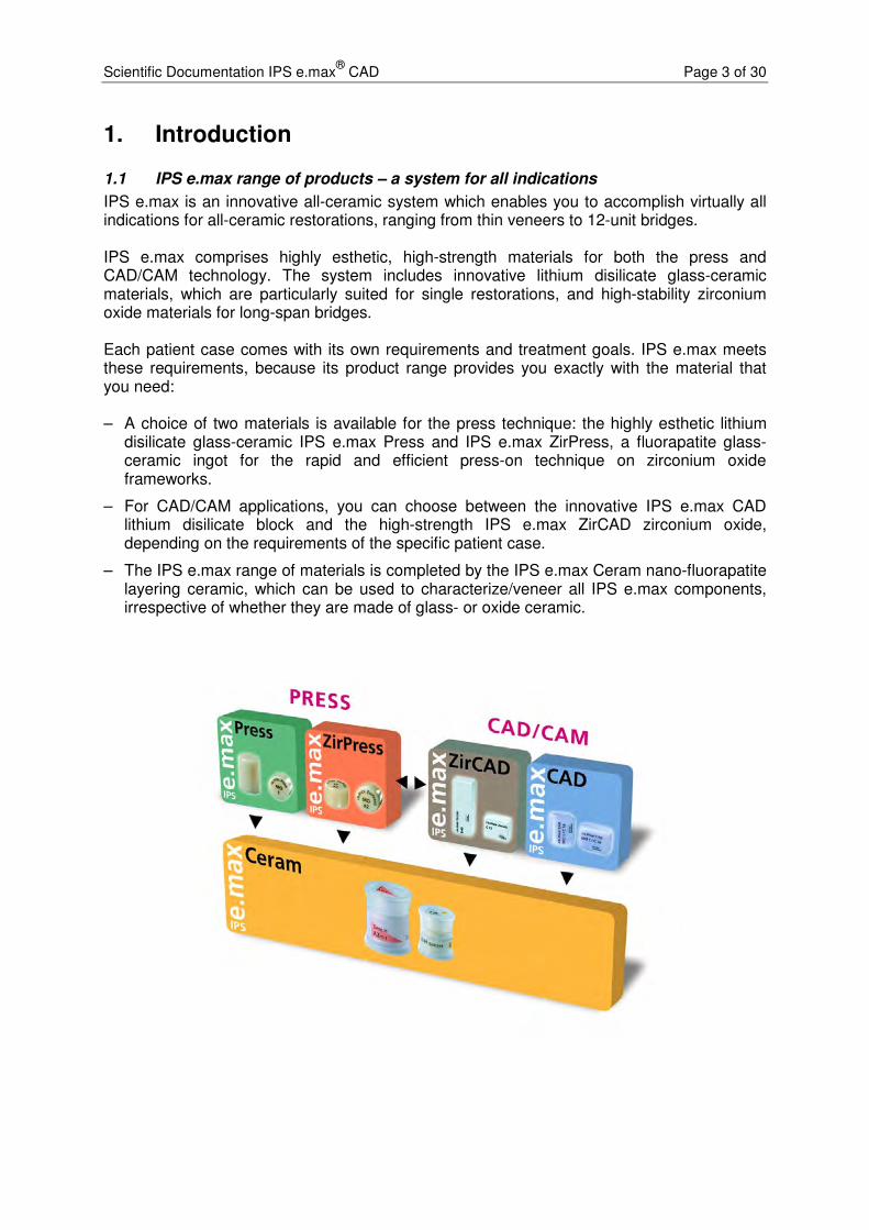
IPS e.max is an innovative all-ceramic system which enables you to accomplish virtually all indications for all-ceramic restorations, ranging from thin veneers to 12-unit bridges. IPS e.max comprises highly esthetic, high-strength materials for both the press and CAD/CAM technology. The system includes innovative lithium disilicate glass-ceramic materials, which are particularly suited for single restorations, and high-stability zirconium oxide materials for long-span bridges. Each patient case comes with its own requirements and treatment goals. IPS e.max meets these requirements, because its product range provides you exactly with the material that you need: – A choice of two materials is available for the press technique: the highly esthetic lithium
disilicate glass-ceramic IPS e.max Press and IPS e.max ZirPress, a fluorapatite glass-ceramic ingot for the rapid and efficient press-on technique on zirconium oxide frameworks.
– For CAD/CAM applications, you can choose between the innovative IPS e.max CAD lithium disilicate block and the high-strength IPS e.max ZirCAD zirconium oxide, depending on the requirements of the specific patient case.
– The IPS e.max range of materials is completed by the IPS e.max Ceram nano-fluorapatite layering ceramic, which can be used to characterize/veneer all IPS e.max components, irrespective of whether they are made of glass- or oxide ceramic.

Scientific Documentation IPS e.max®
CAD Page 4 of 30
1.2 IPS e.max CAD
1.2.1 Overview
IPS e.max CAD is available in three different degrees of translucency: MO, LT and HT.
IPS e.max CAD MO is a tooth-coloured, esthetic framework material, which is veneered with IPS e.max Ceram.
The IPS e.max CAD LT blocks demonstrate a low translucency. They are available in various A to D and Bleach shades. This glass-ceramic allows the fabrication of fully anatomical restorations due to its low translucency and large variety of shades. For highly esthetic results, the restorations can be partially reduced in the labial area and subsequently veneered using IPS e.max Ceram.
The IPS e.max CAD HT blocks are an ideal ceramic for inlays and onlays due to its very high translucency. These ingots exhibit what is known as the chameleon effect, which means that the ceramic reflects the shade of the surrounding dentition.
1.2.2 Material / Manufacture
IPS e.max CAD is a lithium disilicate glass-ceramic (LS2) (Fig. 1) that has been designed for the CAD/CAM technique.
The blocks are cast in one piece (transparent glass ingots, Fig. 2). A continuous production process based on glass technology (pressure-casting procedure) is utilized in the manufacture of the blocks. This new technology, which largely differs from the sintering process employed in the production of Empress/Empress 2 ingots, uses optimized processing parameters, which prevent the formation of defects (pores, accumulation of pigments, etc.) in the body of the block. Partial crystallization ensures that the blocks can be easily processed in an intermediate crystalline phase, enabling rapid machining with CAD/CAM systems (blue state, Fig. 3). The partial crystallization process leads to the formation of lithium metasilicate crystals, Li2SiO3, which are responsible for the material’s favourable processing properties, comparatively high strength and high edge stability.
Following the milling procedure, the restorations are tempered and reach the final state. In the course of this process, lithium disilicate crystals, Li2Si2O5, are formed, which impart the ceramic object with the final shade and desired high strength.
lithiummetasilicate
lithiumorthosilicate
lithiumdisilicate
lithiummetasilicate
lithiumorthosilicate
lithiumdisilicate
Fig. 1: Materials system of SiO2-Li2O, according to Kracek, 1930 [1]

Scientific Documentation IPS e.max®
CAD Page 5 of 30
Fig. 2: Glass ingot
Fig. 3: Partially crystallized blocks
1.2.3 Coloration
The colour of the glasses is produced by colouring ions. The polyvalent colouring elements show a different oxidation state in the intermediate crystalline phase than in the fully crystallized state. Therefore, the blocks (except for MO 0) exhibit a blue colour (Fig. 3, Fig. 4) in the partially crystallized state. The material acquires the desired tooth colour and opacity during tempering, in the course of which the lithium disilicate crystals are formed, and during the subsequent cooling for a defined period of time (Fig. 5).
Fig. 4: Crown in the partially crystallized state
Fig. 5: Crown in the final state
1.2.4 Microstructure
Partially crystallized IPS e.max CAD (Fig. 6):
The microstructure consists of 40% lithium metasilicate crystals (Li2SiO3) embedded in a glassy phase. The grain size of the platelet-shaped crystals is in the range of 0.2 to 1.0 µm.
The etched-out areas show the lithium metasilicate crystals.
Fig. 6: Partially crystallized IPS e.max CAD (SEM, etched with 0.5% HF for 10 s)
Scientific Documentation IPS e.max®
CAD Page 6 of 30
Fully crystallized IPS e.max CAD
(Fig. 7): (tempered at 850°C)
The microstructure consists of approx. 70% fine-grain lithium disilicate crystals, Li2Si2O5, which are embedded in a glassy matrix. By etching with hydrofluoric acid vapour, the glassy phase is dissolved and the lithium disilicate crystals become visible.
Fig. 7: Fully crystallized IPS e.max CAD (SEM, etched with HF vapour for 30 s)
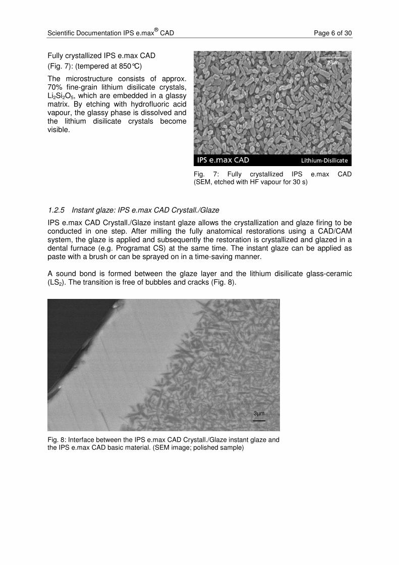
1.2.5 Instant glaze: IPS e.max CAD Crystall./Glaze
IPS e.max CAD Crystall./Glaze instant glaze allows the crystallization and glaze firing to be conducted in one step. After milling the fully anatomical restorations using a CAD/CAM system, the glaze is applied and subsequently the restoration is crystallized and glazed in a dental furnace (e.g. Programat CS) at the same time. The instant glaze can be applied as paste with a brush or can be sprayed on in a time-saving manner. A sound bond is formed between the glaze layer and the lithium disilicate glass-ceramic (LS2). The transition is free of bubbles and cracks (Fig. 8).
3µm3µm
Fig. 8: Interface between the IPS e.max CAD Crystall./Glaze instant glaze and the IPS e.max CAD basic material. (SEM image; polished sample)
Scientific Documentation IPS e.max®
CAD Page 7 of 30
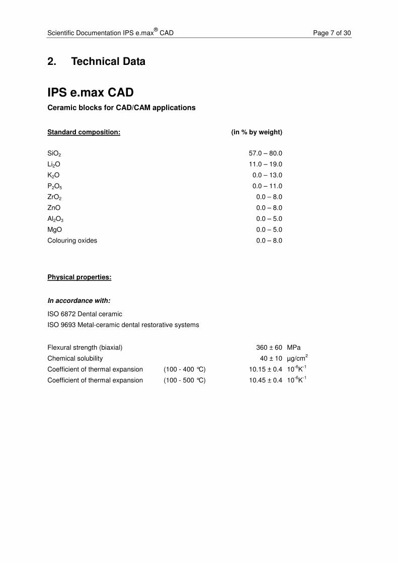
2. Technical Data
IPS e.max CAD Ceramic blocks for CAD/CAM applications
Standard composition: (in % by weight)
SiO2 57.0 – 80.0
Li2O 11.0 – 19.0
K2O 0.0 – 13.0
P2O5 0.0 – 11.0
ZrO2 0.0 – 8.0
ZnO 0.0 – 8.0
Al2O3 0.0 – 5.0
MgO 0.0 – 5.0
Colouring oxides 0.0 – 8.0
Physical properties:
In accordance with:
ISO 6872 Dental ceramic
ISO 9693 Metal-ceramic dental restorative systems
Flexural strength (biaxial) 360 ± 60 MPa
Chemical solubility 40 ± 10 µg/cm2
Coefficient of thermal expansion (100 - 400 °C) 10.15 ± 0.4 10-6
K-1
Coefficient of thermal expansion (100 - 500 °C) 10.45 ± 0.4 10-6
K-1
Scientific Documentation IPS e.max®
CAD Page 8 of 30
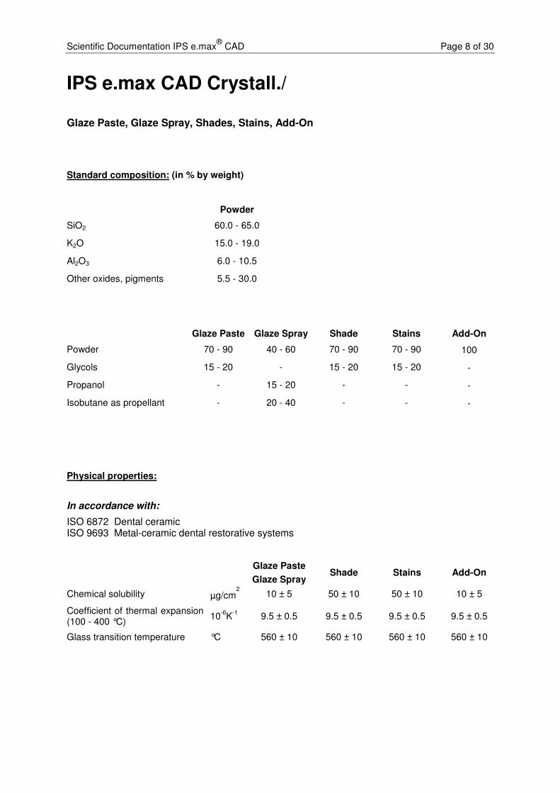
IPS e.max CAD Crystall./
Glaze Paste, Glaze Spray, Shades, Stains, Add-On
Standard composition: (in % by weight)
Powder
SiO2 60.0 - 65.0
K2O 15.0 - 19.0
Al2O3 6.0 - 10.5
Other oxides, pigments 5.5 - 30.0
Glaze Paste Glaze Spray Shade Stains Add-On
Powder 70 - 90 40 - 60 70 - 90 70 - 90 100
Glycols 15 - 20 - 15 - 20 15 - 20 -
Propanol - 15 - 20 - - -
Isobutane as propellant - 20 - 40 - - -
Physical properties:
In accordance with:
ISO 6872 Dental ceramic ISO 9693 Metal-ceramic dental restorative systems
Glaze Paste
Glaze Spray Shade Stains Add-On
Chemical solubility µg/cm2
10 ± 5 50 ± 10 50 ± 10 10 ± 5
Coefficient of thermal expansion (100 - 400 °C)
10-6
K-1
9.5 ± 0.5 9.5 ± 0.5 9.5 ± 0.5 9.5 ± 0.5
Glass transition temperature °C 560 ± 10 560 ± 10 560 ± 10 560 ± 10

Scientific Documentation IPS e.max®
CAD Page 9 of 30
3. Materials Science Investigations
3.1 Physical properties of IPS e.max CAD
Table 1: Physical properties (Ivoclar Vivadent, Schaan, 2005/06)
Physical properties Partially crystallized state
Fully crystallized state
Biaxial strength (ISO 6872) 130 ± 30 MPa 360 ± 60 MPa
Fracture toughness (SEVNB) 0.9 – 1.25 MPa m½ 2.0 – 2.5 MPa m½
Vickers hardness 5400 ± 200 MPa 5800 ± 200 MPa
Modulus of elasticity 95 ± 5 GPa
CTE (100-500 °C) 10.45 ± 0.4 10-6 K-1
Density 2.5 ± 0.1 g/cm3
Linear shrinkage during tempering 0.2%
Chemical solubility 100 – 160 µg/cm2 30 – 50 µg/cm2

Scientific Documentation IPS e.max®
CAD Page 10 of 30
4. In-vitro Investigations
Before IPS e.max CAD was used in clinical applications, its behaviour and performance was tested in several in vitro tests and compared with other materials. These tests provide preliminary information about the performance of the material when it is used for the recommended indications. Although the tests are standardized, they only present a few selected core features and do not provide a comprehensive picture of the material’s performance in vivo. The reported values do not represent absolute values; they are only used as a reference to compare the performance of different materials when they are tested under the same conditions.
4.1 Flexural strength of IPS e.max CAD
Method: The three-point flexural strength of IPS e.max CAD was measured in 400 sample rods, according to ISO 6872. The test samples were milled with a CEREC MCXL or E4D milling unit and further processed in line with the ISO standard protocol. They were also subjected to several real-life clinical conditions, e.g. manual polishing or glazing.
Results: With values ranging from approx. 300 to higher than 400 MPa, IPS e.max CAD exhibited a high flexural strength under all test conditions (Fig. 9) [2].
Fig. 9: Flexural strength values of IPS e.max CAD when subjected to three-point flexural strength testing according to ISO 6872 [2].
4.2 Fatigue behaviour and reliability of IPS e.max CAD
4.2.1 Dr Güß, University Clinic Freiburg, Germany
Objective: To examine the fatigue behaviour and reliability of monolithic CAD/CAM manufactured crowns (Güß et al.) [3].
Method I: Nineteen fully anatomical crowns were designed and milled with a CAD/CAM system. The crowns were etched with 5% hydrofluoric acid
0
50
100
150
200
250
300
350
400
450
500
Sawn, ISO polished & crystallized
Milled & crystallized
IPS e.max CAD
Fle
xu
ral s
tre
ng
th [
MP
a]
ISO sawn
CEREC MCXL
E4D Dentist
Milled, ISO polished & crystallized
Milled, manually polished & crystallized
Milled, manually polished, glazed & crystallized

Scientific Documentation IPS e.max®
CAD Page 11 of 30
for 20 s, silanized with Monobond Plus and adhesively cemented on an artificially aged, dentin-like composite die using Multilink Automix. The samples were stored in water for at least seven days before they were subjected to load/stress testing. During testing, the crowns were exposed to a tungsten carbide indenter, which simulated masticatory movements by shifting along a 0.7 mm path from the distobuccal cusp to the lingual side. Three different levels of load were applied; the highest load was 1000 N. After the tests, the crowns were examined for damage using a stereomicroscope with polarized light.
Results I: The IPS e.max CAD crowns survived these tests without chippings or fractures.
Method II: During the second part of the investigation, the crowns were subjected to a breaking load test.
Results II: The IPS e.max CAD showed a comparatively high load bearing capacity (2576 ± 206 N) and developed fractures that included cracks and reached to the composite core. By contrast, the fractures observed in the IPS e.max ZirCAD test samples were confined to the IPS e.max Ceram veneering ceramic (1195 ± 221 N).
Fig. 10: Fracture load of IPS e.max CAD [3].
Conclusion: Fully anatomical IPS e.max CAD crowns have shown to be resistant to fatigue in cyclic stress/load testing. In comparison, the zirconium oxide crowns failed at considerably lower forces by developing fractures in the veneering material.
500
1000
1500
2000
2500
3000
0
IPS e.max CAD IPS e.max ZirCAD / Ceram
Fra
ctu
re l
oad
[N
]

Scientific Documentation IPS e.max®
CAD Page 12 of 30
4.2.2 Dr Silva, Dr Thompson, New York University, New York, USA
Objective: To examine the fatigue behaviour and reliability of IPS e.max CAD crowns and to compare them to veneered crowns made of zirconium oxide and conventional metal-ceramics [4, 5]. The IPS e.max CAD crowns were CAD/CAM manufactured from a single block. One group of crowns showed an occlusal thickness of 1 mm, while the other group of crowns demonstrated a thickness of 2 mm, with the core being 1.5 mm thick and the buccal veneer 0.5 mm.
Method: For each group, 21 crowns were designed, milled with a CAD/CAM unit and glazed. The crowns were adhesively cemented on an artificially aged, dentin-like composite die using Multilink Automix. The test samples were stored in water for at least 7 days before they were subjected to stress/load testing. The samples were exposed to the force of a tungsten carbide indenter during testing, which simulated masticatory movements by shifting along a 0.7 mm path from the distobuccal cusp to the lingual side. Three different levels of load were applied. After the tests, the crowns were examined for damage using a stereomicroscope with polarized light.
Fig. 11: Weibull strength of zirconium oxide (yellow), metal-ceramic (green), IPS e.max CAD 1 mm (blue) and IPS e.max CAD 2 mm (black) [4, 5].
Results: The characteristic strength (Weibull strength) of the monolithic e.max CAD test samples was 1535 N for e.max CAD 1 mm and 1610 N for e.max CAD 2 mm. These values are similar to those of the metal-

Scientific Documentation IPS e.max®
CAD Page 13 of 30
ceramic samples (1304 N) and higher than those of overlayered zirconium oxide (371 N) (see Fig. 11). Examination of the fractures revealed that complete fractures occurred in the e.max CAD samples and chipping in the two other groups. The e.max CAD material demonstrated the highest reliability.
Conclusion: In this study, the IPS e.max CAD crowns produced similarly favourable values as the gold standard of metal ceramics.
4.3 Luting of IPS e.max CAD
The IPS Empress glass-ceramic has proven to be successful in clinical applications for many years, not least due to its excellent adhesive luting possibilities with materials such as Variolink II. An optimized retentive surface is first created by etching the glass-ceramic with hydrofluoric acid gel of a concentration of approx. 5% (IPS Ceramic Etching Gel). Next, a silanizing agent (e.g. Monobond Plus) is applied onto this surface. The silanized surface helps establish an ideal bond to the luting composite. In comparison to inorganic cements, composites offer a high compressive strength. This is an advantage because the high compressive strength contributes to the fracture strength of the IPS Empress restorations in situ.
IPS e.max CAD features more than double the strength of IPS Empress (160 MPa) and is therefore called a “high-strength” glass-ceramic. Depending on the type of restoration, adhesive cementation is therefore not always required.

Scientific Documentation IPS e.max®
CAD Page 14 of 30
4.3.1 Influence of ceramic etching
Objective: To assess the influence of ceramic etching by means of shear bond strength testing. Vivaglass CEM glass ionomer cement was utilized as luting agent in these tests.
Method: Directly after conditioning, the substrates were cleaned with acetone. Cylinders made of Tetric Ceram were cemented onto the ceramic using Vivaglass CEM and immersed in water for 24 h until the shear bond strength was measured.
Fig. 12: Influence of conditioning with IPS Ceramic Etching Gel on the shear bond strength of lithium disilicate ceramic (LS2) and Vivaglass CEM (Ivoclar Vivadent AG, Schaan, 2006)
Results: A measurable bond to the glass ionomer cement could not be established without a retentive pattern (Fig. 12).
Conclusion: For the above reason, it is necessary to condition the relevant ceramic surfaces with IPS Ceramic Etching Gel for 20 s for the conventional cementation of lithium disilicate ceramics (LS2) (IPS e.max Press and IPS e.max CAD).
0
1
2
3
4
5
6
7
without IPS Ceramic Etching Gel
Conditioning
Sh
ear
bo
nd
str
en
gth
[M
Pa]

Scientific Documentation IPS e.max®
CAD Page 15 of 30
4.3.2 Shear bond tests
Objective: To compare the shear bond strength values of Multilink Automix and Panavia F with those of two self-adhesive luting composites.
Method: The cementation surface of the IPS e.max ceramic probe was conditioned with IPS Ceramic Etching Gel for 20 s. Subsequently, the surface was silanated with Monobond-S silanizing agent for 60 s. The ceramic cylinders were bonded to conditioned human dentin according to the instructions for use of the relevant manufacturer. After having been immersed in water for 24 h, the samples were sheared off.
Results: Adhesive luting with Multilink Automix produced the highest shear bond strength, followed by adhesive luting with Panavia F (Fig. 13).
Fig. 13: Shear bond strength of luting composites between glass-ceramics and dentin (Applied Testing Center, Ivoclar Vivadent Inc., Amherst, 2006)
Conclusion: For the cementation of IPS e.max CAD, adhesive luting composites, such as Multilink Automix or Variolink II, are particularly recommended. Conventional cementation, using for instance the glass-ionomer cement Vivaglass CEM, is also suitable for crowns that have been prepared retentively.
0
5
10
15
20
25
30
35
MaxCEM Panavia F RelyX Unicem
Multilink Automix
Sh
ear
bo
nd
str
en
gth
[M
Pa]
self-curing
light-curing

Scientific Documentation IPS e.max®
CAD Page 16 of 30
4.3.3 Breaking load
Objective: To measure the breaking load of IPS e.max CAD crowns and compare it with that of other ceramic materials (Vita Mark II, Empress CAD). The IPS e.max crowns were cemented using various luting materials.
Method: Seventy-five crowns were milled from each ceramic material. The internal surfaces of the crowns were etched, coated with bonding material and then cemented onto implant abutments. The external surfaces of the abutments were abraded, degreased and coated with bonding agent. The crowns were cemented in place using one out of a selection of five cements (Multilink Implant, Variolink II, Rely X Unicem, FujiCem, Panavia 2.0). After the samples had been subjected to thermocycling (5000 cycles, from 5 to 55 °C), the breaking load was determined in a universal testing machine by stressing the samples with a static load.
Results: On the whole, the highest breaking load values were measured for IPS e.max CAD. Differences between the various luting materials were not detected [6].
Fig. 14: Breaking load of three ceramic materials (Vita Mark II, IPS Empress CAD and IPS e.max CAD) in conjunction with various luting materials [6].
Conclusion: IPS e.max CAD offers high mechanical stability, irrespective of the type of cementation used.
0
500
1000
1500
2000
2500
3000
3500
Multilink
Implant
Variolink II Rely X
Unicem
Fujicem Panavia 2.0
Fra
ctu
re l
oad
[N
]
Vita Mark II
IPS Empress CAD
IPS e.max CAD
Luting material

Scientific Documentation IPS e.max®
CAD Page 17 of 30
4.4 Antagonist wear
Restorations whose occlusal surfaces are comprised of ceramic are subject to wear, similar to natural enamel. Several patient-specific factors have an effect on occlusal wear (e.g. eating habits, parafunctions and bruxism).
4.4.1 Measuring antagonist wear
Wear is a continuous process, which, at first, tends to go almost unnoticed and only becomes manifest over a long period of time. Therefore, dentists often notice wear only if severe localized vertical loss is present or if the loss concerns the entire restoration when they examine the oral cavity of a patient.
Accurately quantifying wear under clinical conditions in situ is very time-consuming. Wear is determined via intraoral impressions, which are measured with laser measuring equipment (initial model and successive models). The accuracy of this measuring method relies on the quality of the impression.
Obviously, the extent of the vertical loss depends on the forces that come to bear on the occlusal surfaces and, consequently, is always unique and patient-specific. The results are affected by the individuals who participate in the study. The masticatory force of men and younger patients is higher than that of women and older people. Eating habits also play a significant role. Consequently, it is vital to examine a sufficiently high number of cases to obtain statistically sound results that can accommodate the variety of individual effects.
In the laboratory, wear is measured in a chewing simulator. The values can only be used for comparisons or as a series of results gathered in conjunction with various other materials because these values are only a partial representation of real-life clinical conditions. Values/samples can only be compared with each other, if they are measured under exactly the same conditions (the tests are not standardized and, consequently, the results usually differ from one another).
Ivoclar Vivadent carries out in-vitro wear tests as follows:
First, the technician selects first or second upper molars whose palatal cusps are similar in terms of shape and steepness (Fig. 15). The cusps are ground and positioned in the central fossa of standardized lower ceramic molars. Masticatory movements are simulated in a Willytec chewing simulator (SD Mechatronik GmbH, Germany) to carry out the wear test. During this test, the antagonist is loaded with 5 kg and moved against the crown 120,000 times, while the crown is shifted laterally by 0.7 mm each time (Fig. 16). The entire test is carried out in a water bath at cyclic temperatures (5°C/55°C). Normally, eight test specimens are tested simultaneously for each material. The wear is quantified with an etkon es1 laser scanner on stone models, which are cast from the original test specimens by means of the replica technique.
Fig. 15: Enamel antagonist ground from the palatal cusp of an upper molar

Scientific Documentation IPS e.max®
CAD Page 18 of 30
Fig. 16: Ceramic crown seated in the test chamber of the Willytec simulator and enamel antagonist cemented onto the sample holder with composite
4.4.2 Effect of material hardness and strength on wear
Ceramic materials are generally known to be comparatively resistant to wear. It is often assumed that materials that exhibit a high level of hardness and strength are more stable in themselves but harsher to antagonist. However, material hardness is often mistaken for strength. Strength indicates how resistant the material or constructional component (restoration) is to deformation when exposed to external forces. By contrast, hardness describes a surface characteristic, which indicates the resistance of a material or structural component to indentation by other objects and may therefore be the result of an interplay with other materials. Strength and hardness are completely independent of each other and do not correlate with one another. For instance, abrasion and wear processes can be minimized by surface hardening processes without affecting the strength of the material. In many technical applications, it is common to increase the surface hardness to obtain a smooth surface and minimize the amount of wear between the two parts that move against each other (e.g. plungers or shaft and cylinder).
Table 2 compares the strength and hardness values of various dental ceramics. It is quite clear from this table that IPS e.max CAD and IPS e.max Press are not harder than the less strong IPS Empress and Mark II (VITA Zahnfabrik) ceramics, even though they offer a high degree of strength.
IPS
Empress IPS e.max
Press IPS e.max
CAD VITA Mark
II Y-TZP
Material Leucite Lithium
disilicate Lithium
disilicate Feldspar
Zirconium oxide
Flexural strength (MPa)
160 400 360 154 900
Vickers hardness
(MPa)
5900 5800 5800 5600 13000
Fracture toughness (MPa m0.5)
1.2 2.7 2.5 1.37 5.5
Table 2: Properties of various dental ceramics

Scientific Documentation IPS e.max®
CAD Page 19 of 30
Conclusion: Neither the hardness nor the strength of a material have a decisive effect on abrasion or wear.
4.4.3 Effect of surface roughness on wear
Wear significantly depends on the friction that occurs between touching materials and is therefore influenced by the surface structure of these materials. Surface roughness represents an essential parameter in this context. Smooth surfaces cause less resistance and consequently produce less wear or abrasion in the opposing material than rough, unpolished surfaces.
Fig. 17: Three-dimensional images of the occlusal surfaces of crowns made of IPS e.max CAD HT and IPS e.max Press after manufacturing (non-finished) and after having been finished with fine diamonds (FRT MicroProf, sample rate of 300Hz, horizontal resolution of 1 µm, vertical resolution of 20 nm). (Ivoclar Vivadent)
After milling in a CAM unit, ceramic restorations demonstrate a detectable surface roughness, which depends on the geometry and grain size of the milling tools. The surface roughness of milled ceramic materials is shown in Figs 15 and 16. After milling, IPS e.max CAD and Vita Mark II exhibit a pronounced surface roughness. Unworked press ceramic materials (Fig. 17) do not exhibit such milling marks, because the viscous conversion of the press ingots results in a smooth surface during the hot pressing procedure. However, the surface roughness of milled ceramic materials can be clearly reduced by finishing the surfaces with diamonds (Figs 17 and 18). For this reason, finishing is recommended.
Milling marks after machining Finishing with diamonds
e.max CAD HT after the milling process
e.max CAD HT after the milling process + finishing with diamonds
e.max Press non-finished
e.max Press after finishing with diamonds
Scientific Documentation IPS e.max®
CAD Page 20 of 30
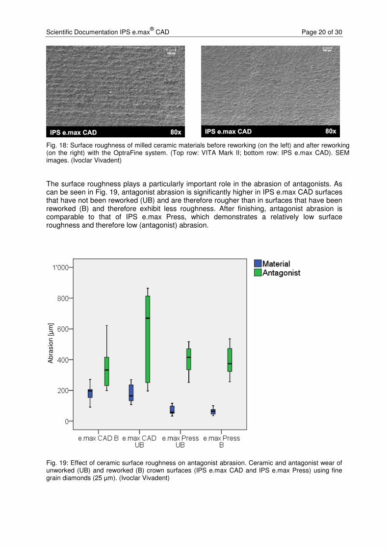
Fig. 18: Surface roughness of milled ceramic materials before reworking (on the left) and after reworking (on the right) with the OptraFine system. (Top row: VITA Mark II; bottom row: IPS e.max CAD). SEM images. (Ivoclar Vivadent)
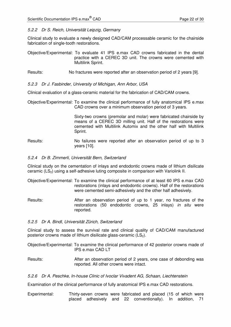
The surface roughness plays a particularly important role in the abrasion of antagonists. As can be seen in Fig. 19, antagonist abrasion is significantly higher in IPS e.max CAD surfaces that have not been reworked (UB) and are therefore rougher than in surfaces that have been reworked (B) and therefore exhibit less roughness. After finishing, antagonist abrasion is comparable to that of IPS e.max Press, which demonstrates a relatively low surface roughness and therefore low (antagonist) abrasion.
Fig. 19: Effect of ceramic surface roughness on antagonist abrasion. Ceramic and antagonist wear of unworked (UB) and reworked (B) crown surfaces (IPS e.max CAD and IPS e.max Press) using fine grain diamonds (25 µm). (Ivoclar Vivadent)
Abra
sio
n [µ
m]

Scientific Documentation IPS e.max®
CAD Page 21 of 30
Conclusion: The initial surface roughness that ceramic objects exhibit after CAM processing does not depend on the ceramic material used. This roughness depends on the milling process and the milling tools used to machine the object. Finishing the ceramic surfaces is essential to minimize antagonist abrasion, particularly in conjunction with milled restorations. To reduce the wear of enamel antagonists, ceramic surfaces should be finished according to the manufacturer’s directions even if the crown will be glazed later on. Glazing alone is not always an equivalent substitute for reworking the surfaces with fine diamonds or polishing of the basic material, because the underlying material will increasingly work on the antagonist either from the beginning or after some (“wear”) time.
5. Clinical Studies
5.1 Clinical studies with IPS e.max CAD MO
5.1.1 Prof. Nathanson, Boston University, Massachusetts, USA
Clinical performance of IPS e.max crowns veneered with IPS e.max Ceram.
Objective/Experimental: To examine the clinical performance of 31 CAD/CAM manufactured lithium disilicate (LS2) crowns.
IPS e.max CAD frameworks were veneered with IPS e.max Ceram and inserted using Multilink and/or Multilink Automix.
Results: After an observation period of up to 3 years, the fracture of 1 crown was recorded (after root canal treatment) [7].
5.1.2 Dr J.A. Sorensen, Pacific Dental Institute, Portland, Oregon, USA
Clinical performance of IPS e.max CAD posterior crowns veneered with IPS e.max Ceram.
Objective/Experimental: Thirty posterior crowns made of IPS e.max CAD frameworks and veneered with IPS e.max Ceram were incorporated. The restorations were cemented using Multilink Automix.
Results: Two crown fractures were reported after an observation period of 2 years.
5.2 Clinical studies with IPS e.max CAD LT, HT
5.2.1 Dr F. Beuer, Poliklinik für Zahnärztliche Prothetik, Munich, Germany
Clinical study on all-ceramic restorations made of CAD/CAM manufactured lithium disilicate ceramics (LS2).
Objective/Experimental: To examine the clinical performance of partially reduced CAD/CAM manufactured lithium disilicate ceramic (LS2) crowns and bridges. Thirty-eight fully anatomical and partially reduced IPS e.max CAD restorations were fabricated in the KaVo Everest milling unit (36 crowns, 2 bridges). The crowns/bridges were veneered with IPS e.max Ceram and cemented with Multilink Sprint.
Results: After an observation period of 2 years, no failures have been reported in the restorations inserted thus far [8].
Scientific Documentation IPS e.max®
CAD Page 22 of 30
5.2.2 Dr S. Reich, Universität Leipzig, Germany
Clinical study to evaluate a newly designed CAD/CAM processable ceramic for the chairside fabrication of single-tooth restorations.
Objective/Experimental: To evaluate 41 IPS e.max CAD crowns fabricated in the dental practice with a CEREC 3D unit. The crowns were cemented with Multilink Sprint.
Results: No fractures were reported after an observation period of 2 years [9].
5.2.3 Dr J. Fasbinder, University of Michigan, Ann Arbor, USA
Clinical evaluation of a glass-ceramic material for the fabrication of CAD/CAM crowns.
Objective/Experimental: To examine the clinical performance of fully anatomical IPS e.max CAD crowns over a minimum observation period of 3 years.
Sixty-two crowns (premolar and molar) were fabricated chairside by means of a CEREC 3D milling unit. Half of the restorations were cemented with Multilink Automix and the other half with Multilink Sprint.
Results: No failures were reported after an observation period of up to 3 years [10].
5.2.4 Dr B. Zimmerli, Universität Bern, Switzerland
Clinical study on the cementation of inlays and endodontic crowns made of lithium disilicate ceramic (LS2) using a self-adhesive luting composite in comparison with Variolink II.
Objective/Experimental: To examine the clinical performance of at least 60 IPS e.max CAD restorations (inlays and endodontic crowns). Half of the restorations were cemented semi-adhesively and the other half adhesively.
Results: After an observation period of up to 1 year, no fractures of the restorations (50 endodontic crowns, 25 inlays) in situ were reported.
5.2.5 Dr A. Bindl, Universität Zürich, Switzerland
Clinical study to assess the survival rate and clinical quality of CAD/CAM manufactured posterior crowns made of lithium disilicate glass-ceramic (LS2).
Objective/Experimental: To examine the clinical performance of 42 posterior crowns made of IPS e.max CAD LT
Results: After an observation period of 2 years, one case of debonding was reported. All other crowns were intact.
5.2.6 Dr A. Peschke, In-house Clinic of Ivoclar Vivadent AG, Schaan, Liechtenstein
Examination of the clinical performance of fully anatomical IPS e.max CAD restorations.
Experimental: Thirty-seven crowns were fabricated and placed (15 of which were placed adhesively and 22 conventionally). In addition, 71

Scientific Documentation IPS e.max®
CAD Page 23 of 30
inlays/onlays/partial crowns were manufactured and placed (all adhesively).
Results: After a mean observation period of 45 months, 2 crown fractures had been reported (one of them was conventionally cemented and broke after 4 years and the other was adhesively placed and broke after 1 year). The recommended occlusal minimum thickness had not been observed in both crowns.
5.3 Conclusion
0
10
20
30
40
50
60
70
Zim
me
rli
Bin
dl
So
ren
se
n
Be
ue
r
Re
ich
Fa
sb
ind
er
Na
tha
ns
on
Pe
sc
hk
e
12
months
24 months 36 months 45
months
Nu
mb
er
of
cro
wn
s
Fractures
Intact crowns
Abb. 20: Intact crowns and fractured crowns reported in clinical studies of up to 45 months to evaluate IPS e.max CAD.
Dr Zimmerli, University of Bern (CH); Dr Bindl, University of Zurich (CH); Dr Sörensen, Pacific Dental Institute, Oregon (USA); Dr Beuer, Poliklinik für Zahnärztliche Prothetik, Munich (D); Dr Reich, Universität Leipzig (D); Dr Fasbinder, University of Michigan (USA); Prof. Nathanson, Boston University (USA); Dr Peschke, Ivoclar Vivadent AG, Schaan (FL).
IPS e.max CAD is a high-strength lithium-disilicate-based glass ceramic. With a strength of 360 MPa, the material is suited to the fabrication of fully anatomical and partially reduced anterior and posterior crowns. It is also suitable for use as framework material for anterior crowns. An overview of the results gained in the clinical studies carried out on this material is given in Fig. 20. Only a few crown fractures occurred, if any at all. Additionally, the material was also tested for the indications of inlays, onlays and veeners. The preparation guidelines and minimum thicknesses stipulated in the Instructions for Use should be followed. Finishing the surfaces should also be carried out as stated in the Instructions. Sandblasting with Al2O3 is explicitly contraindicated to avoid weakening of the ceramic.
Scientific Documentation IPS e.max®
CAD Page 24 of 30
6. Biocompatibility
6.1 Introduction
The ceramic materials used in dentistry are considered to be exceptionally “biocompatible” [11-13]. Biocompatibility is generally regarded as a material’s quality of being compatible with the biological environment (tissues) [14], i.e. the material’s ability to interact with the tissues of the body without causing any, or only very limited biological reactions. A dental material is considered to be “biocompatible” if its function and properties match the biological environment of the body and do not cause any unwanted response [15].
Ceramic materials have enjoyed a good reputation as a biocompatible material [10; 16] and this reputation has steadily grown in the past 40 years. This trend can certainly be attributed to the distinctive properties of these materials. The melting and sintering processes involved in the production and manufacture of these materials eliminate all volatile substances. In addition, the following properties are responsible for the excellent biocompatibility of dental ceramics:
• Harmless ingredients (mainly oxides of silicon, aluminium, sodium and potassium) [11; 16; 17]
• Very low solubility [17]
• High stability in the oral environment, high resistance to acidic foods and liquids [11; 16]
• Low tendency to plaque accretion [11; 16]
• No undesired interaction with other dental materials [11; 16]
• No chemical decomposition involving the release of decomposition products [11; 16]
Generally, ceramics may be described as “bioinert” [14].
The biocompatibility of IPS e.max CAD is discussed in detail below.
6.2 Chemical stability
Dental materials are exposed to a wide range of pH-values and temperatures in the oral cavity. Consequently, chemical stability is an important prerequisite for all dental materials.
According to Anusavice [11], ceramics are considered to be the most durable of all the dental materials.
Chemical solubility of IPS e.max CAD (according to ISO 6872):
Chemical solubility [µg/cm2] Threshold value according to standard [µg/cm2]
IPS e.max CAD 40 ± 10 < 100
(Ivoclar Vivadent AG, Schaan, 2006)
� The chemical solubility of IPS e.max CAD is far below the threshold value specified by the relevant standard.
Scientific Documentation IPS e.max®
CAD Page 25 of 30
Furthermore, an analysis of the ions solved from IPS e.max CAD samples in artificial saliva and acetic acid revealed only a limited amount of detectable ions. The values are comparable to those of other dental materials. Consequently, it is seen as unlikely that soluble components of the ceramic could have any adverse effects, e.g. cause cytotoxicity.
6.3 Cytotoxicity
Cytotoxicity tests provide an indication of the reactivity and tolerance of individual cells (mostly murine fibroblasts) when they are exposed to the soluble compounds of a dental material. Cytotoxicity is the easiest to measure of the biological properties. However, cytotoxicity on its own has only limited validity to appraise the biocompatibility of a dental material. Numerous researchers have been publishing toxicology data on dental materials. The conditions in which the tests are conducted can be selected in such a way that the results vary enormously. This is the reason why cytotoxicity may be detected in some tests but not in others. If the tests show a positive cytotoxic effect, additional, more elaborate tests have to be carried out in order to be able to evaluate the material’s biocompatibility. However, in the end, only the clinical experience gathered with the material allows a conclusive and meaningful assessment of its biocompatibility.
The in vitro toxicity was assessed at NIOM, Scandinavian Institute of Dental Material, Haslum (N), by means of direct cell contact. The test was conducted according to ISO 10993-5: Biological evaluation of medical devices Part 5: Tests for in vitro cytotoxicity.
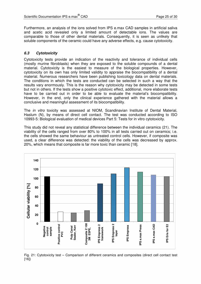
This study did not reveal any statistical difference between the individual ceramics (21). The viability of the cells ranged from over 80% to 100% in all tests carried out on ceramics; i.e. the cells showed the same behaviour as untreated control cells. However, if composite was used, a clear difference was detected: the viability of the cells was decreased by approx. 20%, which means that composite is far more toxic than ceramic [18].
Fig. 21: Cytotoxicity test – Comparison of different ceramics and composites (direct cell contact test [16])
0
20
40
60
80
100
120
140
Neg
ati
ve
co
ntr
ol
sam
ple
Po
sit
ive c
on
tro
l P
VC
Pu
lp C
an
al
Seale
r, K
err
Co
mp
osit
e Z
100
3M
E
SP
E,
IPS
Em
pre
ss 2
fr
am
ew
ork
IPS
Em
pre
ss 2
la
yer
IPS
Em
pre
ss
IPS
e.m
ax P
ress
IPS
e.m
ax C
AD
IPS
Eri
s f
or
E2
Cell
ula
r via
bilit
y [
%]

Scientific Documentation IPS e.max®
CAD Page 26 of 30
Additionally, an agar diffusion test was carried out on IPS e.max CAD LT A1. This cytotoxicity test assesses the response of murine fibroblasts to chemical compounds which dissolve from the test material, diffuse through an agar gel medium and may possibly adversely affect the viability of the cells.
The test showed that e.max CAD LT A1 did not have an adverse effect on the cells after an exposure time of 48 hours [19].
� Under the selected test conditions, no cytotoxic potential could be detected for IPS e.max CAD.
6.4 Sensitization, irritation
Cavazos [20] and Allison et al. [21] have shown that – compared to other dental materials – dental ceramics cause no or only minimal adverse reactions when they come into contact with the oral mucous membrane. Mitchell [22], Podshadley and Harrison [23] used implant tests to prove that glazed ceramics cause only a very limited inflammatory response [22; 23] and cause far less irritation than other approved dental materials, such as gold and resin [23].
In an animal test, hamsters wore IPS e.max CAD LT samples in their pouches for at least 5 minutes per hour during an overall period of 4 hours. Absolutely no irritation of the mucous membrane could be detected [22].
Since direct irritation of the mucous membrane cells through direct contact with ceramics can virtually be ruled out, possible irritation is generally attributable to mechanical stimulus. Normally, such reactions can be prevented by observing the IPS e.max CAD Instructions for Use.
� Compared with other dental materials, ceramics show a lower potential to cause irritation or sensitization, if any at all.
6.5 Radioactivity
Concerns have been raised regarding the possible radioactivity of dental ceramics. The origin of these concerns date back to the seventies, when small amounts of radioactive fluorescent substances were employed in various metal-ceramic systems [25-27]. The possible radiation levels were measured in relation to the ceramic materials in the oral cavity [28]. Several alternatives to attain fluorescence in dental materials without using radioactive additives have become available since the eighties. We may therefore assume that all the major manufacturers stopped using radioactive ingredients in their materials from that time onwards.
Nonetheless, possible sources of radioactivity cannot be so easily ruled out. Minute impurities of uranium or thorium in raw materials, which are sometimes used in their natural state, or in pigments are difficult to remove [25]. Consequently, the standards for ceramic materials (EN ISO 6872; EN ISO 9693; ISO 13356) prohibit the use of radioactive additives and stipulate the maximum level of radioactivity permissible in ceramic materials.
Scientific Documentation IPS e.max®
CAD Page 27 of 30
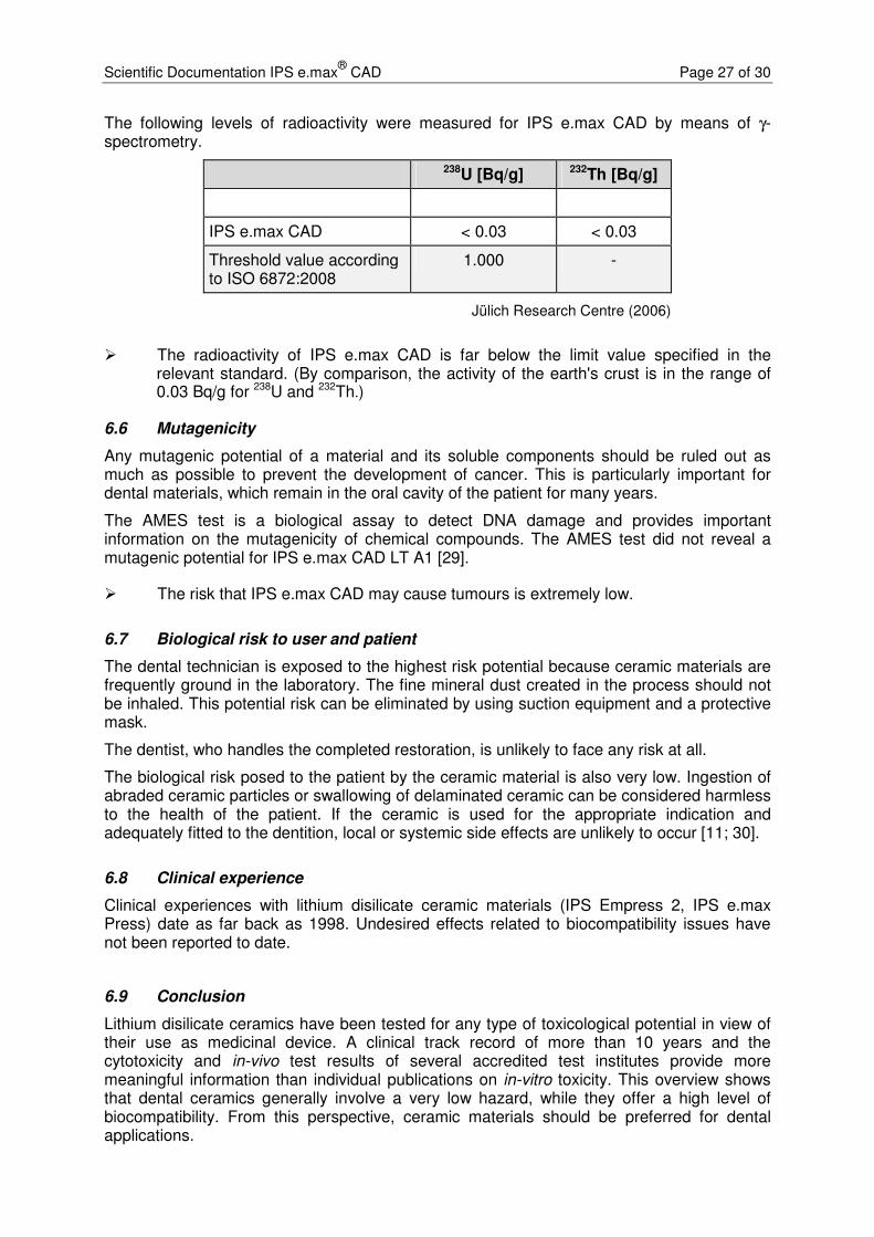
The following levels of radioactivity were measured for IPS e.max CAD by means of γ-spectrometry.
238U [Bq/g] 232Th [Bq/g]
IPS e.max CAD < 0.03 < 0.03
Threshold value according to ISO 6872:2008
1.000 -
Jülich Research Centre (2006)
� The radioactivity of IPS e.max CAD is far below the limit value specified in the relevant standard. (By comparison, the activity of the earth's crust is in the range of 0.03 Bq/g for 238U and 232Th.)
6.6 Mutagenicity
Any mutagenic potential of a material and its soluble components should be ruled out as much as possible to prevent the development of cancer. This is particularly important for dental materials, which remain in the oral cavity of the patient for many years.
The AMES test is a biological assay to detect DNA damage and provides important information on the mutagenicity of chemical compounds. The AMES test did not reveal a mutagenic potential for IPS e.max CAD LT A1 [29].
� The risk that IPS e.max CAD may cause tumours is extremely low.
6.7 Biological risk to user and patient
The dental technician is exposed to the highest risk potential because ceramic materials are frequently ground in the laboratory. The fine mineral dust created in the process should not be inhaled. This potential risk can be eliminated by using suction equipment and a protective mask.
The dentist, who handles the completed restoration, is unlikely to face any risk at all.
The biological risk posed to the patient by the ceramic material is also very low. Ingestion of abraded ceramic particles or swallowing of delaminated ceramic can be considered harmless to the health of the patient. If the ceramic is used for the appropriate indication and adequately fitted to the dentition, local or systemic side effects are unlikely to occur [11; 30].
6.8 Clinical experience
Clinical experiences with lithium disilicate ceramic materials (IPS Empress 2, IPS e.max Press) date as far back as 1998. Undesired effects related to biocompatibility issues have not been reported to date.
6.9 Conclusion
Lithium disilicate ceramics have been tested for any type of toxicological potential in view of their use as medicinal device. A clinical track record of more than 10 years and the cytotoxicity and in-vivo test results of several accredited test institutes provide more meaningful information than individual publications on in-vitro toxicity. This overview shows that dental ceramics generally involve a very low hazard, while they offer a high level of biocompatibility. From this perspective, ceramic materials should be preferred for dental applications.

Scientific Documentation IPS e.max®
CAD Page 28 of 30
In view of the present data and today’s level of knowledge, it can be stated that IPS e.max CAD does not feature any toxic potential. A health risk for patients, dental technicians and dentists can be excluded, provided IPS e.max CAD is used according to the instructions of the manufacturer.
7. References
1. Kracek F. The binary system Li2O - SiO2. PhysChem 1930:2641-2650.
2. Clinician's report. IPS e.max CAD (Lithium Disilicate): A New All-Ceramic Alternative? October 2009; (2):10.
3. Guess PC, Zavanelli RA, Silva NRFA, Bonfante EA, Coelho PG, Thompson VP. Monolithic CAD/CAM Lithium Disilicate Versus Veneered Y-TZP Crowns: Comparison of Failure Modes and Reliability After Fatigue. Int J Prosthodont 2010;23:151-159.
4. Silva, Nelson RFA, Thompson V. Interim Report. Project: Reliability of Reduced Thickness e.max CAD and Thinly Veneered e.max CAD Crowns. New York University. 2010.
5. L.D.M. Martins, P.G. Coelho, G.B. Valverde, E.A. Bonfante, G. Bonfante, E.D. Rekow, V.P. Thompson, N.R.F.A. Silva "Reliability: reduced-thickness and thinly-veneered lithium-disilicate vs. MCR and Y-TZP crowns" IADR Abstract 149736, San Diego, CA, 2011
6. K.M. Lehmann, E. Hell, G. Weibrich, M. Sattari Azar, E. Stender, H. Scheller "Stability of CAD/CAM Crowns on implant abutments using different luting systems" IADR Abstract 146630, San Diego, CA, 2011
7. Nathanson D, IADR abstract #0303, Toronto 2008.
8. Richter J, Schweiger J, Gernet W, Beuer F. Clinical Performance of CAD/CAM-fabricated lithium-disilicate restorations. IADR Abstract #82, Munich 2009.
9. Reich S, Fischer S, Sobotta B, Klapper HU, Gozdowski S. A preliminary study on the short-term efficacy of chairside computer-aided design/computer-aided manufacturing-generated posterior lithium disilicate crowns. Int J Prosthodont 2010;23(3):214-6.
10. Fasbinder DJ, Dennison JB, Heys D, Neiva G. Clinical evaluation of chairside lithium disilicate CAD/CAM crowns. 3-year report. November 2010.
11. Anusavice KJ. Degradability of dental ceramics. Adv Dent Res 1992;6:82-89.
12. McLean J. Wissenschaft und Kunst der Dentalkeramik. Quintessenz Verlags-GmbH; Berlin 1978.
13. Roulet J, Herder S. Seitenzahnversorgung mit adhäsiv befestigten Keramikinlays Quintessenz Verlags-GmbH, Berlin. 1989.
14. Ludwig K. Lexikon der Zahnmedizinischen Werkstoffkunde. Quintessenz Verlags-GmbH; Berlin 2005.
15. Wataha JC. Principles of biocompatibility for dental practitioners. J Prosthet Dent 2001;86:203-209.
16. Anusavice K. Phillips' Science of Dental Materials. Eleventh Edition. W. B. Saunders Company Philadelphia; 2003.
17. Schäfer R, Kappert HF. Die chemische Löslichkeit von Dentalkeramiken. Dtsch Zahnärztl Z 1993;48:625-628.
18. Dahl JE. MTT-test. NIOM Report No. 004/04. 2004.
Scientific Documentation IPS e.max®
CAD Page 29 of 30
19. Grall, F. Toxicon Final GLP Report: 10-1251-G1. Agar Diffusion Test - ISO. April 2010.
20. Cavazos E, Jr. Tissue response to fixed partial denture pontics. J Prosthet Dent 1968;20:143-153.
21. Allison JR, Bhatia HL. Tissue changes under acrylic and porcelain pontics. J Dent Res 1958;37:66-67.
22. Mitchell DF. The irritational qualities of dental materials. J Am Dent Assoc 1959;59:954-966.
23. Podshadley AG, Harrison JD. Rat connective tissue response to pontic material. J Prosthet Dent 1966;16:110-118.
24. Lister S, Toxicon Final GLP Report: 10-1251-G2. Oral Irritation Test - Acute Exposure -- ISO Direct Contact. May 2010.
25. Fischer-Brandies E, Pratzel H, Wendt T. Zur radioaktiven Belastung durch Implantate aus Zirkonoxid. Dtsch Zahnarztl Z 1991;46:688-690.
26. Moore JE, MacCulloch WT. The inclusion of radioactive compounds in dental porcelains. Br Dent J 1974;136:101-106.
27. Viohl J. Radioaktivität keramischer Zähne und Brennmassen. Dtsch Zahnärztl Z 1976;31:860.
28. Sairenji E, Moriwaki K, Shimizu M, Noguchi K. Estimation of radiation dose from porcelain teeth containing uranium compound. J Dent Res 1980;59:1136-1140.
29. Devaki S, Toxikon Final GLP Report: 10-1251-G3: Salmonella typhimurium and Escherichia coli reverse mutation assay - ISO. April 2010.
30. Mackert JR. Side-effects of dental ceramics. Adv Dent Res 1992;6:90-93.

Scientific Documentation IPS e.max®
CAD Page 30 of 30
This documentation contains a survey of internal and external scientific data (“Information”). The documentation and Information have been prepared exclusively for use in-house by Ivoclar Vivadent and for external Ivoclar Vivadent partners. They are not intended to be used for any other purpose. While we believe the Information is current, we have not reviewed all of the Information, and we cannot and do not guarantee its accuracy, truthfulness, or reliability. We will not be liable for use of or reliance on any of the Information, even if we have been advised to the contrary. In particular, use of the information is at your sole risk. It is provided “as-is”, “as available” and without any warranty express or implied, including (without limitation) of merchantability or fitness for a particular purpose. The Information has been provided without cost to you and in no event will we or anyone associated with us be liable to you or any other person for any incidental, direct, indirect, consequential, special, or punitive damages (including, but not limited to, damages for lost data, loss of use, or any cost to procure substitute information) arising out of your or another’s use of or inability to use the Information even if we or our agents know of the possibility of such damages. Ivoclar Vivadent AG Research and Development Scientific Services Bendererstrasse 2 FL - 9494 Schaan Liechtenstein Contents: Dr Kathrin Fischer / Petra Bühler-Zemp / Dr Thomas Völkel Issued: March 2011 Replaces Version: April 2009