Embed Size (px)
Citation preview

FY8-13HU-000
iR1200/iR1300Series
REVISION 0
COPYRIGHT © 2002 CANON INC. 2000 2000 2000 2000 CANON iR1200/iR1300 Series REV. 0 AUG. 2002
AUG. 2002

Application
This manual has been issued by Canon Inc. for qualified persons to learn technical
theory, installation, maintenance, and repair of products. This manual covers all
localities where the products are sold. For this reason, there may be information in this
manual that does not apply to your locality.
Corrections
This manual may contain technical inaccuracies or typographical errors due to
improvements or changes in products. When changes occur in applicable products or in
the contents of this manual, Canon will release technical information as the need arises.
In the event of major changes in the contents of this manual over a long or short period,
Canon will issue a new edition of this manual.
The following paragraph does not apply to any countries where such provisions are
inconsistent with local law.
Trademarks
The product names and company names used in this manual are the registered
trademarks of the individual companies.
Copyright
This manual is copyrighted with all rights reserved. Under the copyright laws, this
manual may not be copied, reproduced or translated into another language, in whole or
in part, without the written consent of Canon Inc.
COPYRIGHT © 2002 CANON INC.
COPYRIGHT © 2002 CANON INC. 2000 2000 2000 2000 CANON iR1200/iR1300 Series REV. 0 AUG. 2002
CautionUse of this manual should be strictly supervised to avoid disclosure of confidential information.

COPYRIGHT © 2002 CANON INC. 2000 2000 2000 2000 CANON iR1200/iR1300 Series REV. 0 AUG. 2002 i
INTRODUCTION
1 Symbols Used
This documentation uses the following symbols to indicate special information:
Symbol Description
Indicates an item requiring care to avoid electric shocks.
Indicates an item requiring care to avoid combustion (fire).
Indicates an item prohibiting disassembly to avoid electric shocks or problems.
Indicates an item requiring disconnection of the power plug from the electricoutlet.
Indicates an item intended to provide notes assisting the understanding of thetopic in question.
Memo
Provides a description of a service mode.
Provides a description of the nature of an error indication.
Refers to the Copier Basics Series for a better understanding of the contents.
Indicates an item of reference assisting the understanding of the topic in ques-tion.REF.
Indicates an item of a non-specific nature, possibly classified as Note, Caution,or Warning.

COPYRIGHT © 2002 CANON INC. 2000 2000 2000 2000 CANON iR1200/iR1300 Series REV. 0 AUG. 2002i i
INTRODUCTION
2 Outline of the Manual
This Service Manual provides basic facts and figures needed to service the iR1200 Series/iR1300 Series products in the field, and it consists of the following chapters:
Chapter 1 Product Outline: specifications, names of parts, safety and warningsChapter 2 Using the Machine: control panel, user mode, service modeChapter 3 Installation: site requirements, installation procedure, work for reloca-
tionChapter 4 Operation: mechanical system by function, principles of operation of
electrical systemsChapter 5 Mechanical System: mechanical construction, disassembly/assemblyChapter 6 Maintenance and Inspection: periodically replaced parts, durables (life), basic servicing
chart, cleaningChapter 7 Troubleshooting: standards/adjustments, troubleshooting image faults,
troubleshooting malfunctionsAppendix: general timing chart, general circuit diagrams

COPYRIGHT © 2002 CANON INC. 2000 2000 2000 2000 CANON iR1200/iR1300 Series REV. 0 AUG. 2002 i i i
INTRODUCTION
The descriptions in this Service Manual are based on he following rules:1. In each chapter, the uses of the function in question and its relationship to electrical and
mechanical systems are discussed and the timing of operation of its associated parts isexplained by means of outlines and diagrams.In the diagrams, the symbol represents a mechanical path, while the symbol
with a name next to it indicates the flow of an electric signal.The expression “turn on the power” means turning on the power switch, closing thefront cover, and closing the delivery cover so that the machine will be supplied withpower.
2. In circuit diagrams (digital), a signal whose level is High is expressed as being ‘1’,while a single whose level is Low is expressed as being ‘0’; the level of voltage, how-ever, varies from circuit to circuit.The machine uses CPUs, whose internal mechanisms cannot be checked in the field,and, therefore, are not explained. In addition, the machine’s PCBs are not intended forrepairs at the user’s and, therefore, are explained by means of block diagrams: two typesare used, i.e., between sensors and inputs of PCBs equipped with a control or drive func-tion and between outputs equipped with a control or drive function and loads; in addi-tion, functional block diagrams are used at times.
Changes made to the machine for product improvement are communicated in the form ofa Service Information bulletin as needed. All service persons are expected to go through allservice documentation including the bulletins and be equipped to respond to the needs of thefield (as by being able to identify possible causes of problems).

COPYRIGHT © 2002 CANON INC. 2000 2000 2000 2000 CANON iR1200/iR1300 Series REV. 0 AUG. 2002i v
INTRODUCTION
The notation “ √” indicates that the item in question is available.
This service manual covers the models shown in the following table. Be sure to have agood understanding of the difference from model to model before referring to this manual.
Model
iR1210
iR1230
iR1270F
iR1310
iR1330
iR1370F
Typecode
MTCPVZQTLUMAUVBUVCUVDUVEZTY
MTDMTEQTMUNAUVFUVGUVHUVJ
MTFMTGUPA
ZTW
ZTZ
ZUB
ADFfunction
√√√√√√√√
√√√
√
√
Printerfunction
√√√√√√√√√
√√√√√√√√
√√√
√
√
√
Faxfunction
√√√
√
Cassette
500 sheet (A4)500 sheet (A4)250 sheet (A4)250 sheet (A4)250 sheet (A4)250 sheet (A4)250 sheet (A4)250 sheet (A4)
250 sheet (Universal)
500 sheet (A4)500 sheet (A4)250 sheet (A4)250 sheet (A4)250 sheet (A4)250 sheet (A4)250 sheet (A4)250 sheet (A4)
250 sheet (A4)500 sheet (A4)250 sheet (A4)
500 sheet (LTR/LGL)
500 sheet (LTR/LGL)
500 sheet (LTR/LGL)
DefaultRatio
4R3E4R3E2R2E2R2E2R2E2R2E2R2E2R2E2R2E
4R3E4R3E2R2E2R2E2R2E2R2E2R2E2R2E
4R3Ε 2R2E4R3Ε
3R2E
3R2E
3R2E
Powersupply
230V230V230V230V230V230V230V230V127V
230V230V230V230V230V230V230V230V
230V230V230V
120V
120V
120V

COPYRIGHT © 2002 CANON INC. 2000 2000 2000 2000 CANON iR1200/1300 Series REV. 0 AUG. 2002 v
CONTENTS
ContentsCHAPTER 1 PRODUCT OUTLINE
CHAPTER 2 USING THE MACHINE1 Using the Machine .............................. 2-1
1.1 Control Panel ............................. 2-12 User Mode .......................................... 2-5
2.1 User Mode Menu ....................... 2-52.2 User Report .............................. 2-18
2.2.1 Manually Generating aReport ................................ 2-18
2.2.2 Automatically GeneratingReports (if equipped withfax functions) ..................... 2-19
2.2.2.1 Memory Clear List ....... 2-20
1 Specifications ...................................... 1-11.1 Type ............................................ 1-11.2 Mechanisms ............................... 1-11.3 Functions .................................... 1-21.4 Others ......................................... 1-41.5 Reproduction Ratio .................... 1-51.6 Copying Speed ........................... 1-6
1.6.1 Copying Speed (AB type,A type) ................................. 1-6
1.6.2 Copying Speed (Inch type) .. 1-71.7 ADF (if equipped with ADF
functions) ................................... 1-81.8 FAX (if equipped fax functions) 1-9
1.8.1 Communicationsspecifications ........................ 1-9
1.8.2 Scanner sectionspecifications ...................... 1-10
1.8.3 Printer sectionspecifications ...................... 1-10
1.8.4 Functions ........................... 1-112 Names of Parts .................................. 1-15
2.1 External View ........................... 1-152.1.1 Body (ADF type) ............... 1-152.1.2 Body (copyboard type) ...... 1-16
2.1.3 ADF (if equipped with ADFfunctions) ........................... 1-18
2.2 Cross Section ........................... 1-192.2.1 Body .................................. 1-192.2.2 ADF (if equipped with ADF
functions) ........................... 1-203 Safety and Warnings ......................... 1-21
3.1 Safety of Laser Light ......... 1-213.1.1 Safety of the Laser Scanner
Unit .................................... 1-213.1.2 CDRH Requirements ......... 1-213.1.3 Handling the Laser Scanner
Unit .................................... 1-223.2 Safety of the Toner ................... 1-233.3 Storing and Handling the Cartridge
(Drum Unit and DevelopingUnit) ......................................... 1-23
3.3.1 Storing a Drum Unit BeforeUnpacking .......................... 1-23
3.3.2 Storing or Handling theCartridge After Unpacking . 1-24
3.3.2.1 Storing After Unpacking 1-243.3.2.2 Points to Note When
Handling the Cartridge . 1-25
3 Service Mode .................................... 2-213.1 Outline ..................................... 2-213.2 Using Service Mode ................ 2-233.3 List of Service Mode Menus ... 2-243.4 Bit Switch Settings
(#1 SSSW) ............................... 2-323.5 Menu Switch Settings
(#2 MENU) .............................. 2-483.6 Numeric Parameter Setting
(#3 NUMERIC Param.) ........... 2-503.7 SPECIAL Setting
(#4A SPECIAL) ....................... 2-55

COPYRIGHT © 2002 CANON INC. 2000 2000 2000 2000 CANON iR1200/1300 Series REV. 0 AUG. 2002v i
CONTENTS
CHAPTER 3 INSTALLATION1 Selecting the Site ................................ 3-12 Unpacking and Installing the
Machine .............................................. 3-22.1 Before Starting ........................... 3-22.2 Installation Procedure ................ 3-22.3 Unpacking .................................. 3-3
2.4 Fitting the Cartridge ................... 3-52.5 Fitting the Toner bottle .............. 3-62.6 Putting Paper in the Cassette ..... 3-82.7 Putting Paper in the Manual
Feed Tray ................................... 3-92.8 Connecting the Interface Cable
................................................. 3-10
3.8 NCU Setting (#4B NCU) ......... 2-553.9 ISDN Setting (#4C ISDN) ....... 2-553.10 Country/Region of Installation
(#5 TYPE) ................................ 2-553.11 Setting the Original Reading
Functions (#6 SCANNER) ...... 2-563.12 Setting the Printer Parameters
(#7 PRINTER) ......................... 2-573.12.1 #1 SSSW Setting ............... 2-573.12.2 #2 NUMERIC Param.
Setting ................................ 2-593.12.3 #3 PRINT COUNT ............ 2-593.12.4 #4 PRINT RESET ............. 2-593.12.5 #5 MLT CLEANING ......... 2-59
3.13 PDL (#8 PDL) .......................... 2-593.14 Counter (#9 COUNTER) ......... 2-60
3.14.1 Counter .............................. 2-603.14.2 Clearing the Counter
Readings ............................ 2-613.15 Generating a Report
(#10 REPORT) ......................... 2-613.16 Downloading
(#11 DOWNLOAD) ................ 2-613.17 Clearing (#12 CLEAR) ............ 2-623.18 ROM Indication (#13 ROM) ... 2-623.19 Resetting the Contact Sensor
Position (#14 CS SET) ............ 2-623.20 Service Mode Default Setting .. 2-633.21 Test Mode (TEST MODE) ...... 2-73
3.21.1 Outline ............................... 2-733.21.2 List of Test Mode Items ..... 2-743.21.3 D-RAM Test (1: D-RAM) . 2-813.21.4 CCD Test (2: CCD TEST) . 2-823.21.5 PRINT Test (3: PRINT) ....... -83
3.21.6 MODEM NCU Test(4: MODEM NCU) ........... 2-84
3.21.6.1 Relay Test ..................... 2-843.21.6.2 Frequency Test .............. 2-853.21.6.3 G3 Signal Transmission
Test ................................ 2-853.21.6.4 DTMF Signal Transmission
Test ................................ 2-863.21.6.5 Tonal/DTMF Signal
Reception Test .............. 2-863.21.6.6. V.34 G3 signal transmission
test ................................. 2-873.21.7 AGING Test
(5: AGING TEST) ............. 2-883.21.8 FACULTY (function) Test
(6: FACULTY TEST) ........ 2-883.21.9 BOOK Read Test
(8: BOOK TEST) .............. 2-943.22 Service Report .......................... 2-95
3.22.1 Manually GeneratingReports ............................... 2-95
3.22.1.1 SYSTEM (SERVICE)DATA LIST ................... 2-95
3.22.1.2 SYSTEM DUMP LIST 2-963.22.1.3 KEY HISTORY
REPORT ....................... 2-983.22.1.4 COUNTER REPORT ... 2-993.22.1.5 PRINT SPEC
REPORT ..................... 2-1003.22.2 Automatically Generated
Reports ............................. 2-1003.22.2.1 Error TX Report
(for service) ................ 2-1013.22.2.2 RX Report
(for service) ................ 2-102

COPYRIGHT © 2002 CANON INC. 2000 2000 2000 2000 CANON iR1200/1300 Series REV. 0 AUG. 2002 vi i
CONTENTS
CHAPTER 4 OPERATION1 Basic Operation .................................. 4-1
1.1 Reproduction Processes ............. 4-11.1.1 Outline ................................. 4-1
1.2 Functional Construction ............ 4-41.3 Outline of the Electrical
Circuitry ..................................... 4-51.3.1 Functional Block Diagram .. 4-51.3.2 Outlines of Functions .......... 4-6
1.3.2.1 Image Processor PCB ..... 4-61.3.2.2 DC Controller PCB ........ 4-71.3.2.3 Control Panel PCB ......... 4-81.3.2.4 Power Supply PCB ......... 4-81.3.2.5 Analog Processor PCB ... 4-91.3.2.6 Sensor PCB ..................... 4-91.3.2.7 Laser Driver/BD PCB ..... 4-91.3.2.8 Main Motor/Scanner
Motor Driver ................... 4-91.3.2.9 Printer Controller PCB ... 4-91.3.2.10 NCU PCB (if equipped
with fax functions) ........ 4-101.3.2.11 Modular Jack PCB
(if equipped with faxfunctions) ...................... 4-10
1.3.2.12 Sensor Relay PCB ........ 4-101.4 Power-On Sequence ................. 4-111.5 Controlling the Main Motor .... 4-12
1.5.1 Outline ............................... 4-122 Image Reading/Processing System ... 4-13
2.1 Outline ..................................... 4-133 Laser Exposure System .................... 4-14
3.1 Outline ..................................... 4-144 Image Formation System .................. 4-16
4.1 Outline ..................................... 4-16
5 Pickup/Feeding/Delivery System ..... 4-175.1 Outline ..................................... 4-175.2 Pickup Operation ..................... 4-18
5.2.1 Pickup from the Cassette ... 4-185.2.1.1 Outline .......................... 4-185.2.1.2 Retry Pickup ................. 4-195.2.1.3 Detecting the Size of
Paper ............................. 4-195.2.2 Pickup from the Manual
Feed Tray ........................... 4-205.2.2.1 Outline .......................... 4-205.2.2.2 Retry Pickup ................. 4-215.2.2.3 Detecting the Size of
Paper ............................. 4-215.3 Feeding Operation/Delivery
Operation ................................. 4-225.3.1 Outline ............................... 4-225.3.2 Auto Delivery Control ....... 4-22
5.4 Reducing the Copying Speed .. 4-235.4.1 Outline ............................... 4-23
5.5 Detecting Jams ......................... 4-245.5.1 Outline ............................... 4-245.5.2 Types of Jams .................... 4-24
6 Fixing System ................................... 4-266.1 Outline ..................................... 4-266.2 Controlling the Fixing
Operation .................................. 4-276.2.1 Controlling the Fixing
Temperature ....................... 4-276.2.2 Controlling the Fixing Film
Bias .................................... 4-296.2.3 Fixing Heater Safety
Mechanism ......................... 4-29
2.9 Connecting the Modular Cable(if equipped with fax functions) ................................ 3-10
2.10 Connecting the Power Cord ..... 3-112.11 Fitting the Delivery Tray .......... 3-112.12 Checking the Copy Images ....... 3-112.13 Setting the Printer Functions .... 3-12
2.14 Setting Fax Functions (if equippedwith fax functions) ................... 3-13
2.14.1 Setting the Date/Time(user mode) ........................ 3-13
2.14.2 Setting the Dial Type ......... 3-142.14.3 Executing Communications
Testing ............................... 3-143 When Relocating the Machine ......... 3-15

COPYRIGHT © 2002 CANON INC. 2000 2000 2000 2000 CANON iR1200/1300 Series REV. 0 AUG. 2002viii
CONTENTS
CHAPTER 5 MECHANICAL SYSTEM1 Points to Note When Disassembling/
Assembling the Machine .................... 5-12 Disassembly ........................................ 5-4
2.1 Externals/Auxiliary System ....... 5-42.1.1 External Covers ................... 5-4
2.1.1.1 Removing the Left Cover/Rear Cover ...................... 5-5
2.1.1.2 Removing the RightCover .............................. 5-5
2.1.1.3 Removing the TonerSupply Cover .................. 5-6
2.1.1.4 Removing the FrontCover .............................. 5-7
2.1.1.5 Removing the DeliveryCover .............................. 5-7
2.1.1.6 Removing the DeliveryUpper Cover/DeliveryRear Cover ...................... 5-8
2.1.1.7 Removing the CartridgeCover .............................. 5-8
2.1.1.8 Removing the UpperCover .............................. 5-9
2.1.1.9 Removing the RightDoor .............................. 5-11
2.1.2 Removing the ControlPanel .................................. 5-11
2.1.3 Removing the CopyboardGlass .................................. 5-13
2.1.4 Removing the Main MotorUnit .................................... 5-14
2.1.5 Remove the Fan ................. 5-172.1.6 Removing the Reader Unit
Slide Detecting Switch ...... 5-192.1.7 Removing the Toner Supply
Cover Switch ..................... 5-202.1.8 Removing the Humidity
Sensor ................................ 5-202.1.9 Removing the Toner Bottle
Sensor ................................ 5-212.1.10 Removing the Waste Toner
Full Sensor ......................... 5-212.2 PCBs ........................................ 5-22
2.2.1 Removing the ImageProcessor PCB ................... 5-22
2.2.2 Removing the AnalogProcessor PCB ................... 5-23
2.2.3 Removing the SensorPCB .................................... 5-25
6.2.4 Detecting a Fault in theFixing Assembly ................ 4-29
7 Power Supply System ....................... 4-317.1 Low Voltage Circuit ................. 4-31
7.1.1 Low Voltage PowerSupply Circuit .................... 4-31
7.1.2 Protective Functions .......... 4-337.2 High-Voltage Power
Supply Circuit .......................... 4-337.3 Controlling the ESS
Mechanism ............................... 4-337.3.1 Outline ............................... 4-337.3.2 Operation ........................... 4-33
8 Others ................................................ 4-348.1 Fan ........................................... 4-34
8.1.1 Outline ............................... 4-348.2 Back-Up Batteries .................... 4-35
8.2.1 Back-Up Function ............. 4-358.2.1.1 Outline .......................... 4-35
8.2.1.2 Lithium Battery (BAT1) ... 4-358.2.1.3 Vanadium Lithium Second-
ary Battery (BAT2) ....... 4-378.2.2 Back-Up Data .................... 4-38
8.2.2.1 Types of Data ................ 4-388.2.2.2 Printing the Backup
Data List ....................... 4-409 ADF (if equipped with ADF
functions) .......................................... 4-419.1 Outline ..................................... 4-419.2 Picking Up and Moving
Originals ................................... 4-429.2.1 Outline ............................... 4-429.2.2 Moving Down the Original
Pickup Roller and Moving Upthe Original Stopper .......... 4-43
9.3 Detecting an Original Jam ....... 4-449.3.1 Outline ............................... 4-449.3.2 Types of Jams .................... 4-44

COPYRIGHT © 2002 CANON INC. 2000 2000 2000 2000 CANON iR1200/1300 Series REV. 0 AUG. 2002 i x
CONTENTS
2.2.4 Removing the DC ControllerPCB/Power Supply PCB ... 5-26
2.2.5 Removing the PrinterController PCB .................. 5-30
2.2.6 Removing the NCU PCB(if equipped with fax functions) .......................... 5-31
2.2.7 Removing the Modular JackPCB .................................... 5-31
2.2.8 Removing the Sensor RelayPCB .................................... 5-31
2.3 Original Reading/Processing System ................... 5-32
2.3.1 Removing the ContactSensor ................................ 5-32
2.3.2 Removing the Reader MotorDrive Unit .......................... 5-33
2.3.3 Removing the Reader Unit 5-352.4 Laser Exposure System ............ 5-37
2.4.1 Removing the Laser ScannerUnit .................................... 5-37
2.5 Image Formation System ......... 5-392.5.1 Removing the Transfer
Charging Roller ................. 5-392.5.2 Removing the Developing
Cylinder/Developing Blade 5-402.5.3 Notes on replacing the
Developing Cylinder/Developing Blade .............. 5-43
2.6 Pickup/Feeding System ........... 5-442.6.1 Removing the Cassette
Pickup Roller ..................... 5-442.6.2 Removing the Cassette
Pickup Solenoid ................. 5-462.6.3 Removing the Manual
Feed Tray (upper) .............. 5-482.6.4 Removing the Manual
Feed Tray (lower) .............. 5-482.6.5 Removing the Manual
Feed Pickup Roller ............ 5-492.6.6 Removing the Separation
Pad ..................................... 5-502.6.7 Removing the Manual Feed
Pickup Solenoid/Manual FeedTray Paper Sensor .............. 5-50
2.6.8 Removing the Vertical PathRoller ................................. 5-51
2.6.9 Removing the RegistrationRoller Unit ......................... 5-54
2.7 Fixing System .......................... 5-552.7.1 Removing the Fixing
Assembly ........................... 5-552.7.2 Removing the Fixing Film Unit/
Fixing Pressure Roller ....... 5-572.7.3 Removing the Delivery
Sensor ................................ 5-582.8 ADF System (if equipped with
ADF functions) ........................ 5-592.8.1 Externals/Auxiliary Control
System ............................... 5-592.8.1.1 Removing the ADF ....... 5-592.8.1.2 Removing the ADF Drive
Unit ............................... 5-612.8.1.3 Removing the ADF Motor
Unit ............................... 5-622.8.1.4 Removing the Slide Guide
(front, rear) ................... 5-632.8.1.5 Mounting the Slide Guide
(front, rear) ................... 5-642.8.2 Pickup System ................... 5-65
2.8.2.1 Removing the SeparationRoller Unit .................... 5-65
2.8.2.2 Removing the OriginalPickup roller/OriginalSeparation roller ........... 5-67
2.8.2.3 Removing the Original Sen-sor/Registration Sensor . 5-67
2.8.2.4 Removing the OriginalSeparation Pad .............. 5-68
2.8.2.5 Removing the ADFRegistration Roller ........ 5-69
2.8.3 Feeding System ................. 5-712.8.3.1 Removing the White
Roller ............................ 5-712.8.3.2 Removing the Feeding
Outside Guide ............... 5-722.8.3.3 Removing the Feed Roll 5-732.8.3.4 Removing the Original
Feed Roller ................... 5-742.8.4 Delivery System................. 5-75
2.8.4.1 Removing the DeliveryStacking Tray/OriginalDelivery Roller ............. 5-75
2.8.4.2 Removing the OriginalDelivery Sensor ............ 5-76

COPYRIGHT © 2002 CANON INC. 2000 2000 2000 2000 CANON iR1200/1300 Series REV. 0 AUG. 2002x
CONTENTS
CHAPTER 6 MAINTENANCE AND INSPECTION
CHAPTER 7 TROUBLESHOOTING
1 Periodically Replaced Parts ................ 6-12 Durables .............................................. 6-13 Scheduled Servicing Chart ................. 6-14 Cleaning .............................................. 6-2
4.1 Cleaning by the User (machine) 6-24.1.1 Cleaning the Fixing Pressure
Roller ................................... 6-24.1.2 Other Cleaning ..................... 6-2
4.2 Cleaning by the User (ADF) ...... 6-34.2.1 Cleaning the White Roller6-34.2.2 Other Cleaning ................ 6-3
4.3 Cleaning at Time of a ServiceVisit (machine) ........................... 6-4
4.3.1 Selfoc Lens Array of theContact Sensor ..................... 6-4
4.3.2 Cassette Pickup Roller ......... 6-54.3.3 Manual Feed Pickup Roller . 6-54.3.4 Separation Pad ..................... 6-54.3.5 Registration Roller ............... 6-5
4.3.6 Transfer Guide ..................... 6-54.3.7 Transfer Charging Roller ..... 6-54.3.8 Separation Static Eliminator . 6-54.3.9 Paper Path ............................ 6-54.3.10 Fixing Inlet Guide ................ 6-54.3.11 Fixing Pressure Roller ......... 6-54.3.12 Delivery Roller ..................... 6-64.3.13 Back of Copyboard Glass
(Back of Shading Plate) ....... 6-64.4 Cleaning at Time of a Service
Visit (ADF) ................................ 6-74.4.1 Original Pickup Roller ......... 6-74.4.2 Original Separation Roller ... 6-74.4.3 Original Separation Pad ....... 6-74.4.4 ADF Registration Roller ...... 6-74.4.5 Original Feed Roller ............ 6-74.4.6 Original Delivery Roller ...... 6-74.4.7 Copyboard Glass
(Original Reading Area) ...... 6-8
1 Standards and Adjustments ................. 7-11.1 Checking Against the
Standards .................................... 7-11.1.1 Checking the Pressure (nip) of
the Fixing Pressure Roller ... 7-11.2 Making Adjustments .................. 7-3
1.2.1 Making Adjustments WhenReplacing Major Parts ......... 7-3
1.2.2 Preparing a Test Sheet forAdjustment .......................... 7-4
1.2.3 Adjusting the Mechanical Systems ............................... 7-5
1.2.4 Adjusting the ElectricalSystems ................................ 7-5
1.2.4.1 Contact Sensor LEDIntensity AutoAdjustment ..................... 7-5
1.2.4.2 Leading Edge Read StartPosition Adjustment ........ 7-6
1.2.4.3 Left/Right Edge ReadStart Position Adjustment 7-7
1.3 Making Adjustments (ADF) ...... 7-81.3.1 Items of Adjustment and
Sequence of Work ................ 7-81.3.2 Preparing a Test Sheet for
Adjustment .......................... 7-81.3.3 Adjusting the Mechanical
Systems ................................ 7-91.3.3.1 Removing the Skew ........ 7-91.3.3.2 Left/Right Registration
Adjustment ................... 7-101.3.4 Adjusting the Electrical
Systems .............................. 7-121.3.4.1 Registration Arch Auto
Adjustment ................... 7-121.3.4.2 Original Read Position
Adjustment .................... 7-12

COPYRIGHT © 2002 CANON INC. 2000 2000 2000 2000 CANON iR1200/1300 Series REV. 0 AUG. 2002 x i
CONTENTS
1.3.4.3 Original SpeedAdjustment ................... 7-13
1.3.4.4 Leading Edge Read StartPosition Adjustment ..... 7-14
1.3.4.5 Trailing Edge Read EndPosition Adjustment ..... 7-15
1.4 When Replacing a Component 7-161.4.1 When Replacing the Image
Processor PCB ................... 7-161.4.1.1 Before Starting the Work7-161.4.1.2 After Finishing the Work7-17
2 Troubleshooting ................................ 7-182.1 Making Initial Checks .............. 7-18
2.1.1 Site Environment ............... 7-182.1.2 Checking the Drum Unit ... 7-182.1.3 Checking the Paper ............ 7-182.1.4 Others ................................ 7-18
2.2 Troubleshooting Flow Chart .... 7-192.3 Making Checks in Response to
an Image Fault ......................... 7-202.3.1 Checking the Originals
Against the Symptom ........ 7-202.3.2 Copyboard Glass and White
Sheet .................................. 7-203 Troubleshooting Image Faults .......... 7-21
3.1 Troubleshooting Procedure forImage Faults ............................. 7-21
3.1.1 The output is too light. ...... 7-223.1.2 The output is too dark. ....... 7-253.1.3 The output is foggy vertically
........................................... 7-263.1.4 The output has fuzzy, black
vertical lines. ...................... 7-263.1.5 The output is foggy
horizontally. ....................... 7-273.1.6 The output has fuzzy, black
horizontal lines. ................. 7-273.1.7 The output has black lines
(vertical). ............................ 7-283.1.8 The output has black lines
(horizontal). ....................... 7-283.1.9 The output has white spots
(vertical). ............................ 7-283.1.10 The output has white lines
(vertical). ............................ 7-28
3.1.11 The output has white spots(horizontal). ....................... 7-29
3.1.12 The output has white lines(horizontal). ....................... 7-29
3.1.13 The output is soiled. .......... 7-303.1.14 The back of the output is
soiled. ................................. 7-313.1.15 The output has a fixing
fault .................................... 7-323.1.16 The output has left/right displace-
ment. .................................. 7-333.1.17 The output has a blurry
image. ................................ 7-333.1.18 The output has poor sharpness
(out of focus). .................... 7-343.1.19 The output is blank. ........... 7-353.1.20 The output is solid black. .. 7-37
4 Troubleshooting Malfunctions ......... 7-384.1 Troubleshooting Malfunctions
(service error) ........................... 7-384.2 Troubleshooting Malfunctions
(other than service error) ......... 7-424.2.1 Power is absent. ................. 7-424.2.2 The LCD fails to operate. .. 7-424.2.3 The contact sensor fails to
move. ................................. 7-434.2.4 The contact sensor LED
fails to go ON. ................... 7-434.2.5 The speaker fails to generate
sound. ................................ 7-444.2.6 The message “CHECK TONER/
DRUM CRG” fails to goOFF ................................... 7-44
4.2.7 The message “SUPPLY REC.PAPER DRAWER:” fails to goOFF. (cassette) ................... 7-45
4.2.8 The message “SUPPLY REC.PAPER S.B.:” fails to go OFF.(manual feed tray) .............. 7-45
4.2.9 The message “REC. PAPERJAM SLIDE PLATEN LEFT”fails to go OFF. .................. 7-46
4.2.10 The message “PLATEN/COVERIS OPEN CLOSE PLATEN/COVER” fails to go OFF. .. 7-47

COPYRIGHT © 2002 CANON INC. 2000 2000 2000 2000 CANON iR1200/1300 Series REV. 0 AUG. 2002xi i
CONTENTS
4.3 Troubleshooting Malfunctions (if equipped with ADFfunctions) ................................. 7-48
4.3.1 Original pickup fails. .......... 7-484.4 Troubleshooting Malfunctions
(printer functions) .................... 7-494.4.1 Printing fails to start. ......... 7-494.4.2 Printing stops in the
middle ................................ 7-494.5 Troubleshooting
(faults unique to models equippedwith fax functions) ................... 7-51
4.5.1 TroubleshootingCommunication Faults ....... 7-51
4.5.2 Service Error Code Output 7-534.5.3 Error Codes ........................ 7-53
4.5.3.1 Transmission Level (ATT):No.07 of Service Soft Switch#2 MENU ..................... 7-53
4.5.3.2 NL Equalizer: No.05 ofService Soft Switch#2 MENU ..................... 7-53
4.5.3.3 Transmission Page Timer:SW12 of Service Soft Switch#1 SSSW....................... 7-53
4.5.3.4 T0 Timer: No.10 of ServiceSoft Switch #3 NUMERICparam. ........................... 7-53
4.5.3.5 T1 Timer: No.11 of ServiceSoft Switch #3 NUMERICparam. ........................... 7-54
4.5.3.6 RTN Signal TransmissionCondition: No. 02, 03, and04 of Service Soft Switch#3 NUMERIC param. ... 7-54
4.5.3.7 Echo Remedy ................ 7-544.5.3.8 Echo Protect Tone: SW03 bit
1 of Service Soft Switch#1 SSSW....................... 7-54
4.5.3.9 Number of Final FlagSequences: SW04 bit 2 ofService Soft Switch#1 SSSW....................... 7-54
4.5.3.10 Subaddress .................... 7-554.5.3.11 Password ....................... 7-55
4.5.3.12 Signals .......................... 7-554.5.3.13 Timer ............................. 7-56
4.5.4 How to Record theProtocol .............................. 7-57
4.5.5 Causes and Remedies forUser Error Codes ............... 7-58
4.5.6 Causes and Remedies forService Error Codes ........... 7-63
4.5.7 Common Faults ................. 7-855 Troubleshooting Feeding Faults ....... 7-86
5.1 Outline ..................................... 7-865.2 Paper Jams ............................... 7-87
5.2.1 Pickup Assembly (cassette) 7-875.2.2 Pickup Assembly
(manual feed tray) .............. 7-895.2.3 Feeding Assembly ............. 7-915.2.4 Fixing Delivery Assembly . 7-935.2.5 Checking the Rotation of the
Rollers and Gears .............. 7-945.2.5.1 Checking the Rotation of the
Cassette Pickup Roller andthe Vertical Path Roller . 7-94
5.2.5.2 Checking the Rotation of theRegistration Roller and theGear for the PhotosensitiveDrum ............................. 7-94
5.3 Original Jams (if equipped withADF functions) ........................ 7-95
5.4 Feeding Faults .......................... 7-965.4.1 Double Feeding ................. 7-965.4.2 Wrinkles ............................ 7-97
5.5 Faulty Feeding of Originals (ifequipped with ADF functions) 7-98
5.5.1 Double Feeding ................. 7-985.5.2 Skew .................................. 7-98
6 Arrangement of the Electrical Parts .. 7-996.1 Checking the
Photointerrupters ...................... 7-996.2 Arrangement and Functions of
Electrical Components ........... 7-1016.2.1 Solenoids, Motors, Fans .. 7-101
6.2.1.1 Body ........................... 7-1016.2.1.2 ADF (if equipped with
ADF functions) ........... 7-102
COPYRIGHT © 2002 CANON INC. 2000 2000 2000 2000 CANON iR1200/1300 Series REV. 0 AUG. 2002 xiii
CONTENTS
APPENDIX
6.2.2 Sensors ............................ 7-1036.2.2.1 Body ........................... 7-1036.2.2.2 ADF (if equipped with
ADF functions) ........... 7-1046.2.3 Others .............................. 7-1056.2.4 PCBs ................................ 7-107
1 General Timing Chart ........................ A-12 General Circuit Diagram.................... A-3
6.3 Variable Resistors, Light EmittingDiodes (LED), and CheckPins by PCB ........................... 7-109
6.3.1 Image Processor PCB ...... 7-1096.3.2 DC Controller PCB .......... 7-110
3 List of Special Tools .......................... A-54 List of Solvents and Oils ................... A-6


COPYRIGHT © 2002 CANON INC. 2000 2000 2000 2000 CANON iR1200/iR1300 Series REV. 0 AUG. 2002
CHAPTER 1
PRODUCT OUTLINE


1-1
CHAPTER 1 PRODUCT OUTLINE
COPYRIGHT © 2002 CANON INC. 2000 2000 2000 2000 CANON iR1200/iR1300 Series REV. 0 AUG. 2002
1 Specifications
1.1 Type
1.2 Mechanisms
Item
BodyCopyboard glassLight sourceLensPhotosensitive medium
Specifications
Desk top (ADF standard type, copyboard standard type)FixedLEDCIS (contact sensor)OPC drum (30-mm dia.) : Drum unit
Item
ReproductionChargingExposureCopy density adjustmentDevelopmentPickup
TransferSeparateCleaningFixing
Specifications
Indirect electrostaticRoller contactSemiconductor laserAuto or manualDry, 1-component toner projectionCassette: 1 cassetteMultifeeder: 1 feederRoller transferStatic (static eliminator) + curvatureRubber bladeSURF (on-demand)

CHAPTER 1 PRODUCT OUTLINE
1-2 COPYRIGHT © 2002 CANON INC. 2000 2000 2000 2000 CANON iR1200/iR1300 Series REV. 0 AUG. 2002
1.3 Functions
Item
Resolutionprinter enginecopyprint
Original typeMaximum original sizeReproduction ratioZoomWait timeFirst copy time
Continuous reproductionReproduction size
250-sheet cassette(Fixed to A4 size)250-sheet cassette(Universal)500-sheet cassetteManual feed tray
Paper type250-sheet cassette
500-sheet cassette
Manual feed tray
CassetteManual feed tray capacityDelivery tray capacityNon-image width
Specifications
600 x 600 dpi1200 equivalent x 600 dpi2400 equivalent x 600 dpiSheet, book, 3-D object (2 kg max.)A4 (297 × 210 mm / 11.7" × 8.3"), LGL (356 × 216 mm / 14.0" × 8.5")AB:4R3E, A:2R2E, Inch:3R2E50% to 200% (1% increments)8.5 sec (after plug in) / 1.0 sec (after pressing Energy Saver key)13 sec or less21.5 sec (after plug in)18 sec (after pressing Energy Saver key)99 pages max.
A4
LGL, LTR, A4, B5
LGL, LTR, A4Width: 76.2 to 216 mm (3.0" to 8.5")Length: 127 to 356 mm (5.0" to 14.0")Weight: 56 to 128 g/m2
Plain paper (64 to 80 g/m2), recycled paper (64 to 80 g/m2), col-ored paper (64 to 80 g/m2)Plain paper (64 to 80 g/m2), recycled paper (64 to 80 g/m2), col-ored paper (64 to 80 g/m2)Plain paper (64 to 80 g/m2), recycled paper (64 to 80 g/m2), col-ored paper (64 to 80 g/m2), transparency, tracing paper, label,postcard, thick paper (56 to 128 g/m2), envelopeClaw separation, front loading10 mm deep, (about 100 sheets of 80 g/m2 paper)100 sheets max.Leading edge: 3.0 ± 2.0 mm (0.12" ± 0.08"), left/right edge: 2.5 ±2.0 mm (0.10" ± 0.08")

1-3
CHAPTER 1 PRODUCT OUTLINE
COPYRIGHT © 2002 CANON INC. 2000 2000 2000 2000 CANON iR1200/iR1300 Series REV. 0 AUG. 2002
ItemAEImage modeToner save modeSpecial mode
Auto power-offPower save mode
N-on-11-on-N memory copyAuto copy startJam recoveryAuto clearDate/time setWeekly timerToner level detection*3
Cassette paper level detectionLGL size detectionToner supply cover open/closeddetectionToner bottle position detectionHumidity sensorWaste toner full detectione-Maintenance
SpecificationsYesYes (text, text/photo, photo)YesYes: Tracing paper mode, transparency mode, special paper 1
mode*1, special paper 2 mode*2
NoYes (manually ON/OFF, auto OFF after specific time, auto ONafter fax reception/print data reception)Yes (in some functions, 2-on-1)YesYesYesYesYesYesYesYesYes
YesYesYesYesYes
*1: Thick paper mode; including paper of 105 to 128 g/m2 and Bond paper with poor sur-face characteristics.
*2: Thick paper H mode; envelope, etc.*3: At this time, the copier/printer is capable of printing only so many prints, suspending
operation thereafter.In the case of fax, select “Print” or “Remain the image data in the memory” at the usermode display in advance. Follow the action selected at the user mode.
CHAPTER 1 PRODUCT OUTLINE
1-4 COPYRIGHT © 2002 CANON INC. 2000 2000 2000 2000 CANON iR1200/iR1300 Series REV. 0 AUG. 2002
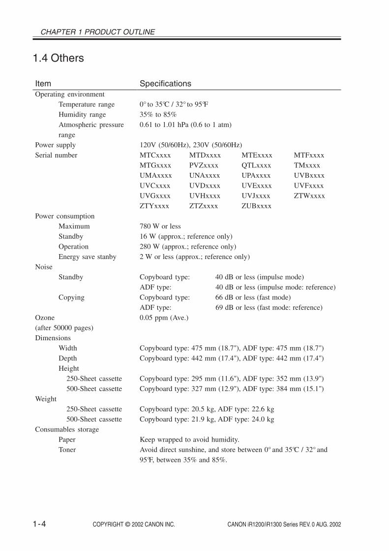
1.4 Others
ItemOperating environment
Temperature rangeHumidity rangeAtmospheric pressurerange
Power supplySerial number
Power consumptionMaximumStandbyOperationEnergy save stanby
NoiseStandby
Copying
Ozone(after 50000 pages)Dimensions
WidthDepthHeight
250-Sheet cassette500-Sheet cassette
Weight250-Sheet cassette500-Sheet cassette
Consumables storagePaperToner
Specifications
0° to 35°C / 32° to 95°F35% to 85%0.61 to 1.01 hPa (0.6 to 1 atm)
120V (50/60Hz), 230V (50/60Hz)MTCxxxx MTDxxxx MTExxxx MTFxxxxMTGxxxx PVZxxxx QTLxxxx TMxxxxUMAxxxx UNAxxxx UPAxxxx UVBxxxxUVCxxxx UVDxxxx UVExxxx UVFxxxxUVGxxxx UVHxxxx UVJxxxx ZTWxxxxZTYxxxx ZTZxxxx ZUBxxxx
780 W or less16 W (approx.; reference only)280 W (approx.; reference only)2 W or less (approx.; reference only)
Copyboard type: 40 dB or less (impulse mode)ADF type: 40 dB or less (impulse mode: reference)Copyboard type: 66 dB or less (fast mode)ADF type: 69 dB or less (fast mode: reference)0.05 ppm (Ave.)
Copyboard type: 475 mm (18.7"), ADF type: 475 mm (18.7")Copyboard type: 442 mm (17.4"), ADF type: 442 mm (17.4")
Copyboard type: 295 mm (11.6"), ADF type: 352 mm (13.9")Copyboard type: 327 mm (12.9"), ADF type: 384 mm (15.1")
Copyboard type: 20.5 kg, ADF type: 22.6 kgCopyboard type: 21.9 kg, ADF type: 24.0 kg
Keep wrapped to avoid humidity.Avoid direct sunshine, and store between 0° and 35°C / 32° and95°F, between 35% and 85%.

1-5
CHAPTER 1 PRODUCT OUTLINE
COPYRIGHT © 2002 CANON INC. 2000 2000 2000 2000 CANON iR1200/iR1300 Series REV. 0 AUG. 2002
1.5 Reproduction Ratio
Item
DirectReduce IReduce IIReduce IIIReduce IVReduce VReduce VIEnlarge IEnlarge IIEnlarge IIIEnlarge IV
4R3E(AB configuraiton)
1 : 1.0001 : 0.500
1 : 0.707
1 : 0.8161 : 0.8651 : 1.154
1 : 1.4141 : 2.000
2R2E(A configuration)
1 : 1.0001 : 0.500
1 : 0.707
1 : 1.4141 : 2.000
3R2E(Inch configuration)
1 : 1.0001 : 0.5001 : 0.647
1 : 0.786
1 : 1.294
1 : 2.000

CHAPTER 1 PRODUCT OUTLINE
1-6 COPYRIGHT © 2002 CANON INC. 2000 2000 2000 2000 CANON iR1200/iR1300 Series REV. 0 AUG. 2002
1.6 Copying Speed1.6.1 Copying Speed (AB type, A type)
Size
A4 (210 × 297mm / 8.3" × 11.7")B5 (182 × 257mm / 7.2" × 10.1")A5 (149 × 210mm / 5.9" × 8.3")A4R → postcardA4R → A5RB5R → A5RA4R → B5R
B5R → A4RA5R → A4Rpostcard → A4R
*1: If the manual feed tray is in use, the copying speed is indicated assuming that the papersize setting is correct.
*2: AB-configured paper only.*3: In the case of “Special paper 2 mode” selected at the user menu.
The machine performs 3-step copying speed reduction control designed to prevent crack-ing of the fixing heater, otherwise possibly occurring as a result overheating of the ends ofthe fixing assembly. (See 5.4 of Chapter 4.)
Manualfeed tray*1
1213136 *3
131313
121212
Ratio
Direct
Reduce I (50.0%)III (70.7%)V*2 (81.6%)VI*2 (86.5%)
EnlargeI *2 (115.4%)III (141.4%)IV (200.0%)
Paper size
A4B5A5
postcardA5A5B5
A4A4A4
Cassette
1213----
13
121212
copies/min

1-7
CHAPTER 1 PRODUCT OUTLINE
COPYRIGHT © 2002 CANON INC. 2000 2000 2000 2000 CANON iR1200/iR1300 Series REV. 0 AUG. 2002
1.6.2 Copying Speed (Inch type)
Ratio
Direct
Reduce I (50.0%)II (64.7%)IV (78.6%)
Enlarge II (129.4%)IV (200.0%)
Size
LTR (216 × 279mm / 8.5" × 11.0")LGL (216 × 356mm / 8 .5" × 14.0")STMTR (139 × 216mm / 5.5" × 8.5")MINLGL → STMTLGL → LTR
STMTR → LTRRMAX (LTR)
Paper size
LTRLGL
STMTSTMTSTMTLTR
LTRLTR
copies/minCassette
1310---
13
1313
Manualfeed tray*1
131013131313
1313
*1: If the manual feed tray is in use, the copying speed is indicated assuming that the papersize setting is correct.
The machine performs 3-step copying speed reduction control designed to prevent crack-ing of the fixing heater, otherwise possibly occurring as a result overheating of the ends ofthe fixing assembly. (See 5.4 of Chapter 4.)

CHAPTER 1 PRODUCT OUTLINE
1-8 COPYRIGHT © 2002 CANON INC. 2000 2000 2000 2000 CANON iR1200/iR1300 Series REV. 0 AUG. 2002
1.7 ADF (if equipped with ADF functions)
The machine may not be able to handle the following types of originals:• original with a carbon back• original made of multiple layers (pasted, bound)• original with a cut-off, 5 or more holes, or tear• original with a clip, adhesive tape, or glue• original with curling, wrinkling, or appreciable bending• transparency
Advise the user to remove as much curling as possible, if any, and place the original in theoriginal tray so that the side with the curling is the trailing edge.
Items
PickupOriginal typeOriginal size
Original orientationOriginal positionOriginal processing modeOriginal readingStack
Mixed original sizesOriginal AE detectionOriginal size recognitionStampPower supplyOperating environment
Specifications
Auto pickup/delivery (top separation by double-pad)Single-sided sheet (50 to 128 g/m2)A4R, B5R, A5R, B6, LGL, LTRR, STMTRLength: 128 to 356 mm (5" to 14"), width: 139 to 216 mm (5.5" to8.5")Face-downCenter referenceFrom single-sided to single-sidedStream reading30 sheets or less (if A4/LTR or smaller)15 sheets or less (if LGL)Yes (only if of the same paper configuration)NoNoNoFrom host (5 VDC and 24 V)Same as host

1-9
CHAPTER 1 PRODUCT OUTLINE
COPYRIGHT © 2002 CANON INC. 2000 2000 2000 2000 CANON iR1200/iR1300 Series REV. 0 AUG. 2002
1.8 FAX (if equipped fax functions)1.8.1 Communications specifications
Applicable linesAnalog line (one line)• PSTN (Public Switched Telephone Network)
Transmission methodHalf-duplex
Transmission control protocolITU-T T.30 binary protocol/ECM protocol
Modulation methodG3 image signals ITU-T V.27ter (2.4kbps, 4.8kbps)
ITU-T V.29 (7.2kbps, 9.6kbps)ITU-T V.17 (14.4kbps, 12kbps, TC9.6kbps, TC7.2kbps)ITU-T V.34 (2.4Kbps, 4.8Kbps, 7.2Kbps, 9.6Kbps, 12Kbps,14.4Kbps, 16.8Kbps, 19.2Kbps, 21.6Kbps, 24Kbps, 26.4Kbps,28.8Kbps, 31.2Kbps, 33.6Kbps)
G3 procedure signals ITU-T V.21 (No.2) 300bpsITU-T V.8, V34 (300bps, 600bps, 1200bps)
Transmission speed33.6Kbps, 31.2Kbps, 28.8Kbps, 26.4Kbps, 24Kbps, 21.6Kbps, 19.2Kbps, 16.8Kbps,14.4Kbps, 12Kbps, TC9.6Kbps, TC7.2Kbps, 9.6Kbps, 7.2Kbps, 4.8Kbps, 2.4KbpsWith automatic fallback function
CodingMH, MR, MMR, JBIG
Error correctionITU-T ECM
Canon express protocolNone
Transmission output levelfrom 0 to -15 dBm
Minimum receive input level-43 dBm (at. V.17)
Modem ICCONEXANT FM336

CHAPTER 1 PRODUCT OUTLINE
1-10 COPYRIGHT © 2002 CANON INC. 2000 2000 2000 2000 CANON iR1200/iR1300 Series REV. 0 AUG. 2002
1.8.2 Scanner section specifications
Scanning methodContact sensor scanning method
Scanning line densityHorizontal: Standard/Fine/Superfine 203.2 dpi (8 dots/mm) Ultrafine 406.4 dpi (16 dots/mm) (Interpolated)Vertical: Standard 97.79 dpi (3.85 lines/mm) Fine 195.58 dpi (7.7 lines/mm) Superfine/Ultrafine 391.16 dpi (15.4 lines/mm)
Scanning density adjustmentLight, Standard, Dark: The density level of each mode can be selected
by the user mode menu.
Half tone64-gradation error diffusion system
1.8.3 Printer section specifications
Printing resolution600dpi × 600dpi
Reduction for receptionFixed reduction (75%, 90%, 95%, 97%)Auto reduction (70~100%)

1-11
CHAPTER 1 PRODUCT OUTLINE
COPYRIGHT © 2002 CANON INC. 2000 2000 2000 2000 CANON iR1200/iR1300 Series REV. 0 AUG. 2002
1.8.4 Functions
STAMPNone
FAX/TEL switchingMethod CNG detectionMessage NonePseudo CI None
Answering machine connectionYes (Telephone answering priority type)CNG detection
DPRDYes
PollingPolling transmissionNone
Polling receptionReceives from a fax in automatic transmission modeOne touch locations Max. 12
Confidential receptionNone
Confidential transmissionNone
Remote receptionMethod ID call# (ID input method)Remote ID (with ID call#) 2 digits (Default : 25)
Memory receptionYes
CHAPTER 1 PRODUCT OUTLINE
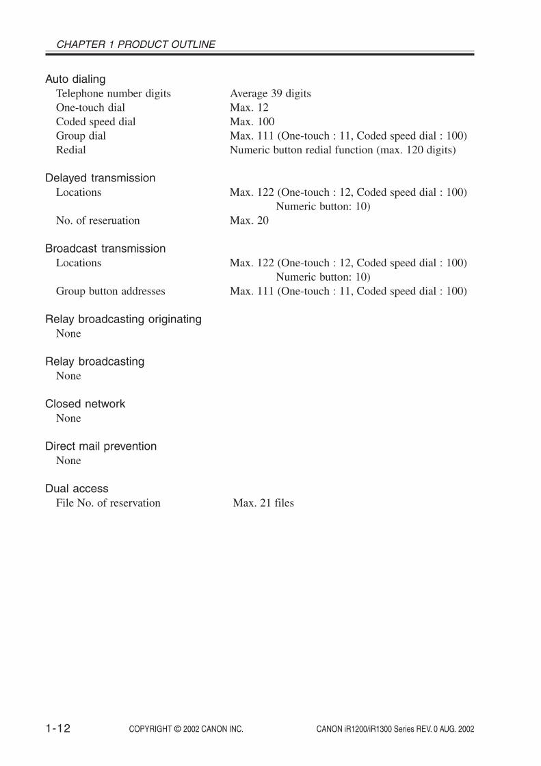
1-12 COPYRIGHT © 2002 CANON INC. 2000 2000 2000 2000 CANON iR1200/iR1300 Series REV. 0 AUG. 2002
Auto dialingTelephone number digits Average 39 digitsOne-touch dial Max. 12Coded speed dial Max. 100Group dial Max. 111 (One-touch : 11, Coded speed dial : 100)Redial Numeric button redial function (max. 120 digits)
Delayed transmissionLocations Max. 122 (One-touch : 12, Coded speed dial : 100)
Numeric button: 10)No. of reseruation Max. 20
Broadcast transmissionLocations Max. 122 (One-touch : 12, Coded speed dial : 100)
Numeric button: 10)Group button addresses Max. 111 (One-touch : 11, Coded speed dial : 100)
Relay broadcasting originatingNone
Relay broadcastingNone
Closed networkNone
Direct mail preventionNone
Dual accessFile No. of reservation Max. 21 files

1-13
CHAPTER 1 PRODUCT OUTLINE
COPYRIGHT © 2002 CANON INC. 2000 2000 2000 2000 CANON iR1200/iR1300 Series REV. 0 AUG. 2002
Activity managementa) User report
Activity report(Every 20 transactions)TX/RX report1-touch spd dial listCoded speed dial listGroup dial listMemory clear listUser data listMulti activity reportDocument memory list
b)Service reportSystem data listSystem dump listKey history reportCounter reportPrint spec report
Transmitting terminal identificationItems Time, telephone No. (max 20 digits), senders ID, address,
number of transmitted pages (max 3 digits)Address Can be registered with one-touch/ coded speed dial keys
(16 characters)Senders ID 20 characters (1 name)
Program keyNone
RedialInterval 2 min. (from 2 to 99 min. can be selected in user data)Count 2 times (from 1 to 10 times can be selected in user data)
Memory backupBackup contents dial registration data, user data, service data, timeBackup IC 128 Kbyte SRAMBackup battery Lithium battery 3.0 V DC / 560 mAhBattery life Approx. 5 years

CHAPTER 1 PRODUCT OUTLINE
1-14 COPYRIGHT © 2002 CANON INC. 2000 2000 2000 2000 CANON iR1200/iR1300 Series REV. 0 AUG. 2002
Image data backupBackup contents Memory reception, delayed transmission
and broadcast transmission image data, activitymanagement report
Backup IC 16 Mbyte SDRAMBackup coding method JBIGBackup battery Rechargeable vanadium lithium battery 3.0V DC/ 50 mAhBattery life 40 cycles with 100% discharge
(Temperature 77°F (25°C))
Timeprecision ±60 sec per month
The foregoing specifications are subject to change for product improvement.
1-15
CHAPTER 1 PRODUCT OUTLINE
COPYRIGHT © 2002 CANON INC. 2000 2000 2000 2000 CANON iR1200/iR1300 Series REV. 0 AUG. 2002
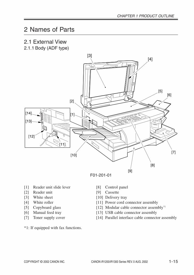
2 Names of Parts
2.1 External View2.1.1 Body (ADF type)
[1]
[2]
[5][6]
[7]
[9]
[10]
[11]
[12]
[13]
[14]
[3][4]
[8]
F01-201-01
[1] Reader unit slide lever[2] Reader unit[3] White sheet[4] White roller[5] Copyboard glass[6] Manual feed tray[7] Toner supply cover
[8] Control panel[9] Cassette[10] Delivery tray[11] Power cord connector assembly[12] Modular cable connector assembly*1
[13] USB cable connector assembly[14] Parallel interface cable connector assembly
*1: If equipped with fax functions.

CHAPTER 1 PRODUCT OUTLINE
1-16 COPYRIGHT © 2002 CANON INC. 2000 2000 2000 2000 CANON iR1200/iR1300 Series REV. 0 AUG. 2002
2.1.2 Body (copyboard type)
[1]
[2]
[6]
[7]
[10]
[12]
[11]
[3]
[4][5]
[8]
[9]
F01-201-02
[1] Reader unit slide lever[2] Reader unit[3] Copyboard cover[4] Copyboard glass[5] Manual feed tray[6] Toner supply cover
[7] Control panel[8] Cassette[9] Delivery tray[10] Power cord connector assembly[11] USB cable connector assembly[12] Parallel interface cable connector assembly

1-17
CHAPTER 1 PRODUCT OUTLINE
COPYRIGHT © 2002 CANON INC. 2000 2000 2000 2000 CANON iR1200/iR1300 Series REV. 0 AUG. 2002
[4][5]
[2]
[3]
[1]
F01-201-03
[1] Drum shutter stopper[2] Cartridge cover[3] Cartridge
[4] Right door[5] Shipping screw slot

CHAPTER 1 PRODUCT OUTLINE
1-18 COPYRIGHT © 2002 CANON INC. 2000 2000 2000 2000 CANON iR1200/iR1300 Series REV. 0 AUG. 2002
2.1.3 ADF (if equipped with ADF functions)
[4]
[3][2][1]
F01-201-04
[1] Original placement area[2] Open/close cover
[3] Delivery slot[4] Slide guide

1-19
CHAPTER 1 PRODUCT OUTLINE
COPYRIGHT © 2002 CANON INC. 2000 2000 2000 2000 CANON iR1200/iR1300 Series REV. 0 AUG. 2002
2.2 Cross Section2.2.1 Body
[1] [2] [3] [4] [5] [6] [7] [8] [9] [10]
[23] [22] [20] [18] [16] [14] [12]
[21] [19] [17] [15] [13] [11]
F01-202-01
[1] Contact sensor[2] Copyboard[3] Laser scanner motor unit[4] Laser unit[5] Reflecting mirror[6] Cartridge[7] Reader unit[8] Registration shutter[9] Manual feed pickup roller[10] Manual feed tray[11] Right door[12] Vertical path roller
[13] Registration roller[14] Cassette pickup roller[15] Developing cylinder[16] Transfer charging roller[17] Separation static eliminator[18] Photopositive drum[19] Fixing film unit[20] Fixing pressure roller[21] Delivery roller[22] Cassette[23] Delivery tray

CHAPTER 1 PRODUCT OUTLINE
1-20 COPYRIGHT © 2002 CANON INC. 2000 2000 2000 2000 CANON iR1200/iR1300 Series REV. 0 AUG. 2002
2.2.2 ADF (if equipped with ADF functions)
[1] [2] [3] [4] [5] [6] [7]
[8]
[9]
[10][11][12][13][14][15]
F01-202-02
[1] Slide guide[2] Open/close cover[3] Original pickup roller[4] Original feed/separation roller[5] Original delivery tray[6] Original delivery roller[7] Original delivery sensor[8] Delivery external guide[9] Original feed roller[10] Contact sensor (body)[11] White roller[12] ADF registration roller[13] Registration sensor[14] Original separation pad[15] Original sensor

1-21
CHAPTER 1 PRODUCT OUTLINE
COPYRIGHT © 2002 CANON INC. 2000 2000 2000 2000 CANON iR1200/iR1300 Series REV. 0 AUG. 2002
3 Safety and Warnings
3.1 Safety of Laser Light3.1.1 Safety of the Laser Scanner Unit
The radiation from a laser until can be harmful to the human body. The machine’s laserscanner unit is sealed by means of a protective housing and external covers, so that the lightit produces will not escape outside, ensuring the safety of the user as long as the machine isused under normal conditions.
3.1.2 CDRH RequirementsThe Center for Devices and Radiological Health (CDRH) of the US Department of Health
and Human Services put into force a set of requirements with a view to regulating laser-re-lated products on August 2, 1976. The requirements apply to laser products produced onAugust 1, 1996, or later, and all laser products must comply with them if they are to be mar-keted in the US. The following is the label that indicates the compliance with the CDRH re-quirements, and it must be attached to all laser products that are sold in the US.
#1
23
45
6
78
9
0
OK
F01-301-01
The text may differ from product to product or from model to model.

CHAPTER 1 PRODUCT OUTLINE
1-22 COPYRIGHT © 2002 CANON INC. 2000 2000 2000 2000 CANON iR1200/iR1300 Series REV. 0 AUG. 2002
3.1.3 Handling the Laser Scanner UnitWhen servicing the area around the machine’s laser scanner unit, take full care not to put
any tool with a high reflectance (e.g., screwdriver) into the laser path. Be sure also to re-move any watch, ring, or the like, as they can reflect the laser beam to damage your eye. Themachine’s laser light is red, and its covers that can reflect the laser beam are identified usingthe following label. The laser scanner unit of this model cannot be adjusted in the field.
FAX
COPY
#
12
34
56
78
90
0102
0304
0506
0708
0910
1112
Energy Serve
In Use / MemoryAlarmStop / Reset
Start
ABC
DEFJKL
MNO
PQRS
TUV
WXYZOPERSYMBOLS
TONE
GHI
2 In 1
Collate
Copy Ratio
Paper Select
Exposure
Image Quality
Additional Functions
Set
FunctionRadial / PauseCorded DialDirectry
SendingResolution
R
D.T.
Tone / +Space
Delete
Clear
Fax MonitorMemoryReference
ReportDelayedTransmissionBook Sending
Recieve Mode
F01-301-02
The label is attached to covers inside the machine used to block out laserradiation.

1-23
CHAPTER 1 PRODUCT OUTLINE
COPYRIGHT © 2002 CANON INC. 2000 2000 2000 2000 CANON iR1200/iR1300 Series REV. 0 AUG. 2002
3.2 Safety of the Toner
The machine’s toner is a non-toxic material consisting of plastic, iron, and small amountsof dye. If toner came into contact with your skin or clothes, remove as much of it as possiblewith dry tissue, and wash with water. Do not use hot water, as it will turn the toner into ajelly and cause it to permanently fuse with the fibers of the clothes. Also, do not bring tonerinto contact with vinyl material, as they are likely to react against each other.
Do not throw toner into fire. It may explode.
3.3 Storing and Handling the Cartridge(Drum Unit and Developing Unit)
Whether it is left packed or unpacked, or is fitted to the machine, the cartridge is subjectto the effects of the environment, and will deteriorate over time. The speed of deteriorationdepends on the site or storage condition, and cannot be generalized. Take full care whenstoring or handing it.
3.3.1 Storing a Drum Unit Before Unpacking
If the drum unit is to be stored in a storeroom or a workshop, be sure to refer to T01-303-01, and keep the following in mind:
• Avoid direct sunshine.• Avoid vibration.• Avoid impact. (Take care not to drop it.)

CHAPTER 1 PRODUCT OUTLINE
1-24 COPYRIGHT © 2002 CANON INC. 2000 2000 2000 2000 CANON iR1200/iR1300 Series REV. 0 AUG. 2002
2.5 yr (approx.)
Severe (1/10 of total storage period)High
Low
Change in temperature (within about 3 min)
Normal (9/10 of total storage period)
Severe (1/10 of total storage time)
Atmospheric pressure
Effective period of cartridge
High
Low
Tem
pera
ture
Hum
idity
Normal (9/10 of total storage period)
0.61~1.01hpa
10~35%RH
85~95%RH
35~85%RH
40~15˚C/104~59˚F-20~25˚C/-4~77˚F
-20~0˚C/-4~32˚F
35~40˚C/95~104˚F
0~35˚C/32~95˚F
T01-303-01
3.3.2 Storing or Handling the Cartridge After Unpacking
The photosensitive drum is made of organic photo-conducting material (OPC), and willdeteriorate if exposed to strong light. It is also used to hold toner inside it after setting thetoner bottle. Be sure to advise the user to be fully careful when storing and handling the car-tridge. (The cartridge must always be put inside a protective bag for storage.)
3.3.2.1 Storing After Unpackinga. Use a protective bag for storage.b. Avoid areas subject to direct sunshine (e.g., near a window). Do not leave it alone inside
a card, as the temperature can rise to an extremely high level. (These are also true even ifthe cartridge is put in a protective bag.)
c. Avoid areas subject to high temperature/humidity or low temperature/humidity, areassubject to rapid changes in temperature or humidity, or areas subject to condensation(e.g., near an air conditioner).
d. Avoid areas exposed to corrosive gas (e.g., insecticide) or salty air.e. Avoid areas subject to dust, ammonium gas, or organic solvent gas.

1-25
CHAPTER 1 PRODUCT OUTLINE
COPYRIGHT © 2002 CANON INC. 2000 2000 2000 2000 CANON iR1200/iR1300 Series REV. 0 AUG. 2002
f. Avoid areas near a CRT display, disk drive, and floppy disk. (The magnetism from thecartridge can destroy the data.)
g. Keep it out of reach of children.h. Keep the temperature between 0° and 35°C (32° and 95°F).
3.3.2.2 Points to Note When Handling the Cartridgea. Do not shake the cartridge after setting the toner bottle.b. Do not place the cartridge on its end or upside down as shown in F01-303-01. Also, do
not swing it.
F01-303-01
c. Do not touch the surface of the drum unit.
F01-303-02

CHAPTER 1 PRODUCT OUTLINE
1-26 COPYRIGHT © 2002 CANON INC. 2000 2000 2000 2000 CANON iR1200/iR1300 Series REV. 0 AUG. 2002
d. Do not touch the developing cylinder.
F01-303-03
e. Do not disassemble the cartridge.f. Do not subject the cartridge to unnecessary vibration or impact. In particular, do not
force down on the photosensitive drum through the shutter found under the cartridge.g. Do not keep the cartridge inside the machine when moving the machine. Be sure to put
the cartridge in its protective bag, or wrap it in thick cloth to avoid light.h. Do not place the cartridge near a CRT display, disk drive, or floppy disk, as the magne-
tism from the cartridge can destroy the data.i. Keep the cartridge out of reach of children.j. The photosensitive drum is susceptible to light, thus the presence of a shutter under the
cartridge. If exposed to strong light for a long time, the copies may start to developwhite spots or vertical bands. These faults may disappear if the machine is left at rest forsome time, or the memory (cause of the faults) may remain permanently.
If you must take out the cartridge from the machine, be sure to put it in itsprotective bag, or cover it. Never leave it alone unprotected.
Memo
If the photosensitive drum is exposed to 1500 lux (general light) for 5 minand then left alone for 5 min in a dark place, it may recover to a level thatwill not cause practical problems. Nevertheless, avoid direct sunshine by allmeans, which is as strong as 10000 to 30000 lux.

1-27
CHAPTER 1 PRODUCT OUTLINE
COPYRIGHT © 2002 CANON INC. 2000 2000 2000 2000 CANON iR1200/iR1300 Series REV. 0 AUG. 2002
k. Advise the user to send all used drum unit to the designated place.
Do not throw a drum unit (used or not used) into fire. It may burst or ex-plode.
Whenever possible, keep the drum unit intact with the developing unit. If you mustseparate the drum unit and the developing unit as when checking image faults, be sure tokeep it in a protective bag to prevent damage to the drum surface.
l. Be sure to use the drum shutter stopper as replacing the drum unit.m. Use the packaging box of the new drum unit if available.


COPYRIGHT © 2002 CANON INC. 2000 2000 2000 2000 CANON iR1200/iR1300 Series REV. 0 AUG. 2002
CHAPTER 2
USING THE MACHINE


COPYRIGHT © 2002 CANON INC. 2000 2000 2000 2000 CANON iR1200/iR1300 Series REV. 0 AUG. 2002 2-1
CHAPTER 2 USING THE MACHINE
1 Using the Machine
The functions and LEDs found in the machine’s control panel are as follows:
1.1 Control Panel
ABC DEF
GHI JKL MNO
PQRS TUV WXYZ
Report
MemoryReference
Fax Monitor
DelayedTransmission
Book Sending
Clear
Delete
Space
Tone/+
Function
Redial / Pause
Coded Dial
Directory
Receive Mode
Fax Resolution
D.T.
R
[1] [2] [3] [4] [5] [6] [7] [8] [9]
[10][11][13][14][21] [15][16]
[19][20]
[22] [17]
[18]
[12]
OK
F02-101-01
[1] Additional Functions KeyPress it to bring up the user mode menu for making various settings and registeringitems. The key flashes when the machine is in user mode menu, and goes OFF in re-sponse to a press.
[2] LCDUse it to refer to the Copy/Fax basic screen, various Settings screens, and error mes-sages.
[3] Collate KeyPress it to select sorting. The key remains ON when the machine is in sort mode, andgoes OFF in response to a press.
[4] 2 on 1 KeyPress it to reduce 2 originals automatically and on a single sheet.
[5] Copy Key*1
Press it when using a copier function. The key remains ON when the machine is incopier mode.
[6] Fax Key*1
Press it when using a fax function. The key remains ON when the machine is in fax mode.
*1: If equipped with fax functions.

CHAPTER 2 USING THE MACHINE
COPYRIGHT © 2002 CANON INC. 2000 2000 2000 2000 CANON iR1200/iR1300 Series REV. 0 AUG. 20022-2
[7] In Use/Memory Lamp*1
It goes ON when an original has been read, a delayed fax transmission has been se-lected, or memory reception has been used. Further, it flashes while fax transmission isunder way.
[8] Alarm LampIt flashes when a fault has occurred in the machine (e.g., paper jam).
[9] Energy Saver KeyPress it to manually select or deselect energy save mode. It remains ON when the ma-chine is in energy save mode, and goes OFF when the machine leaves the mode.
[10] Stop/Reset KeyPress it to stop making copies or transmitting a fax. Or, press it to reset the machinewhite making mode settings (i.e., to return copier/fax mode to standard mode).
[11] Start KeyPress it to start making a copy or sending a fax.
[12] # KeyPress it to enter a “symbol” when register ing fax/telephone number or when entering afax telephone number.
[13] KeypadUse it to enter a copy count or a value for Zoom, or when entering a fax telephonenumber.
[14] * KeyPress it to generate a tone signal from a dial (pulse) circuit when using a fax function.
[15] Right Arrow/+ KeyPress it to add a value when making various settings or to indicate the next setting oran item.
[16] Image Quality KeyPress it to select a copy image quality type (text, text/photo, photo).
[17] Paper Select KeyPress it to select a source of paper (drawer (cassette), stack bypass (manual feed)).
[18] OK Key (Set Key*2)Press it to store various selections or settings.
[19] Exposure KeyPress it to change the copy density. (auto, or manual from 9 steps)
[20] Enlarge/Reduce KeyPress it to select a default Enlarge/Reduce ratio or Zoom.
[21] Left Arrow/- KeyPress it to subtract a value when making various settings or to indicate the previoussetting or an item.
[22] One-Touch/Fax Function Key (after a press on the Function key)*1
Press it to dial a pre-registered telephone number. A press on the Function key willcause it to serve as the Fax Function key.
*1: If equipped with fax functions.*2: Only for the iR1310/1330/1370F models.
COPYRIGHT © 2002 CANON INC. 2000 2000 2000 2000 CANON iR1200/iR1300 Series REV. 0 AUG. 2002 2-3
CHAPTER 2 USING THE MACHINE
[1] [2] [3]
[17]
[16]
[15]
[14]
[13]
[4]
[5]
[6]
[7]
[8]
[9]
[12] [11] [10]
Report
MemoryReference
Fax Monitor
DelayedTransmission
Book Sending
Clear
Delete
Space
Tone/+
Function
Redial / Pause
Coded Dial
Directory
Receive Mode
Fax Resolution
D.T.
R
F02-101-02
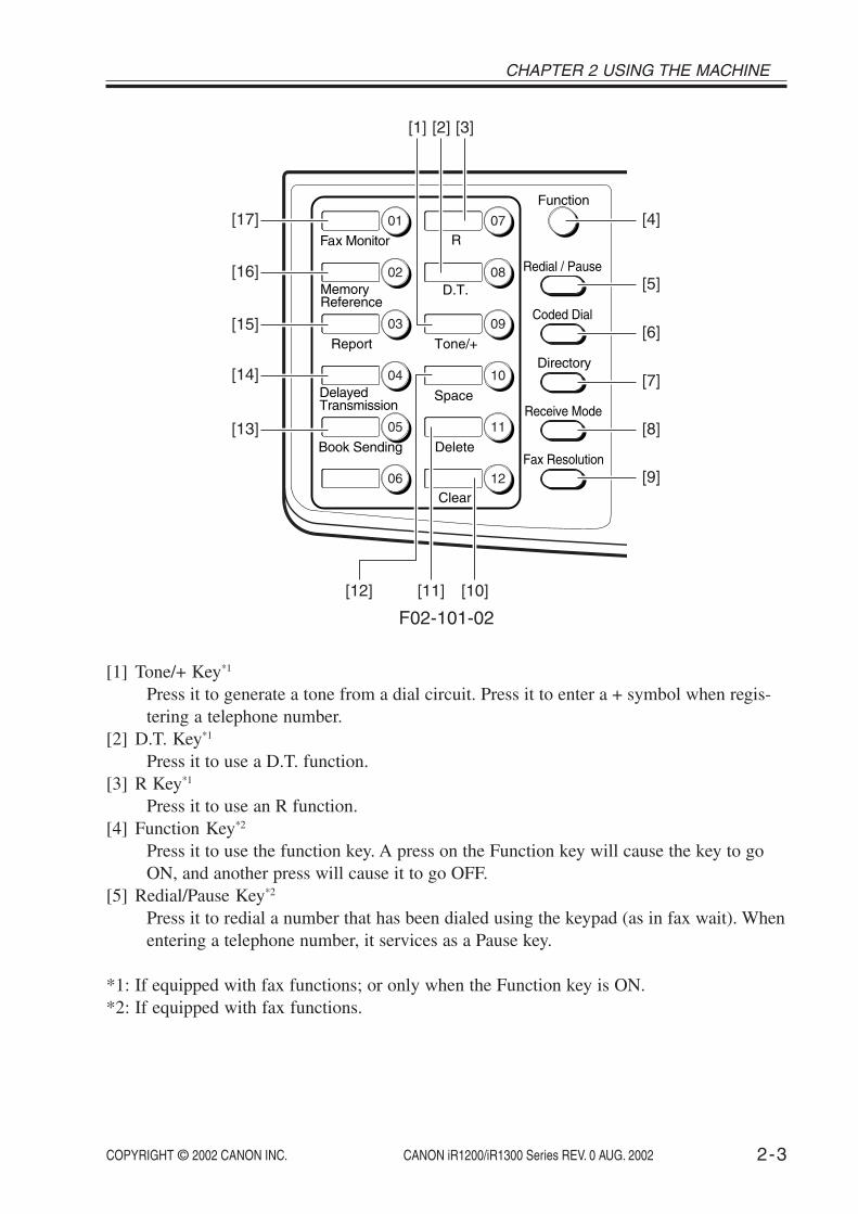
[1] Tone/+ Key*1
Press it to generate a tone from a dial circuit. Press it to enter a + symbol when regis-tering a telephone number.
[2] D.T. Key*1
Press it to use a D.T. function.[3] R Key*1
Press it to use an R function.[4] Function Key*2
Press it to use the function key. A press on the Function key will cause the key to goON, and another press will cause it to go OFF.
[5] Redial/Pause Key*2
Press it to redial a number that has been dialed using the keypad (as in fax wait). Whenentering a telephone number, it services as a Pause key.
*1: If equipped with fax functions; or only when the Function key is ON.*2: If equipped with fax functions.
CHAPTER 2 USING THE MACHINE
COPYRIGHT © 2002 CANON INC. 2000 2000 2000 2000 CANON iR1200/iR1300 Series REV. 0 AUG. 20022-4
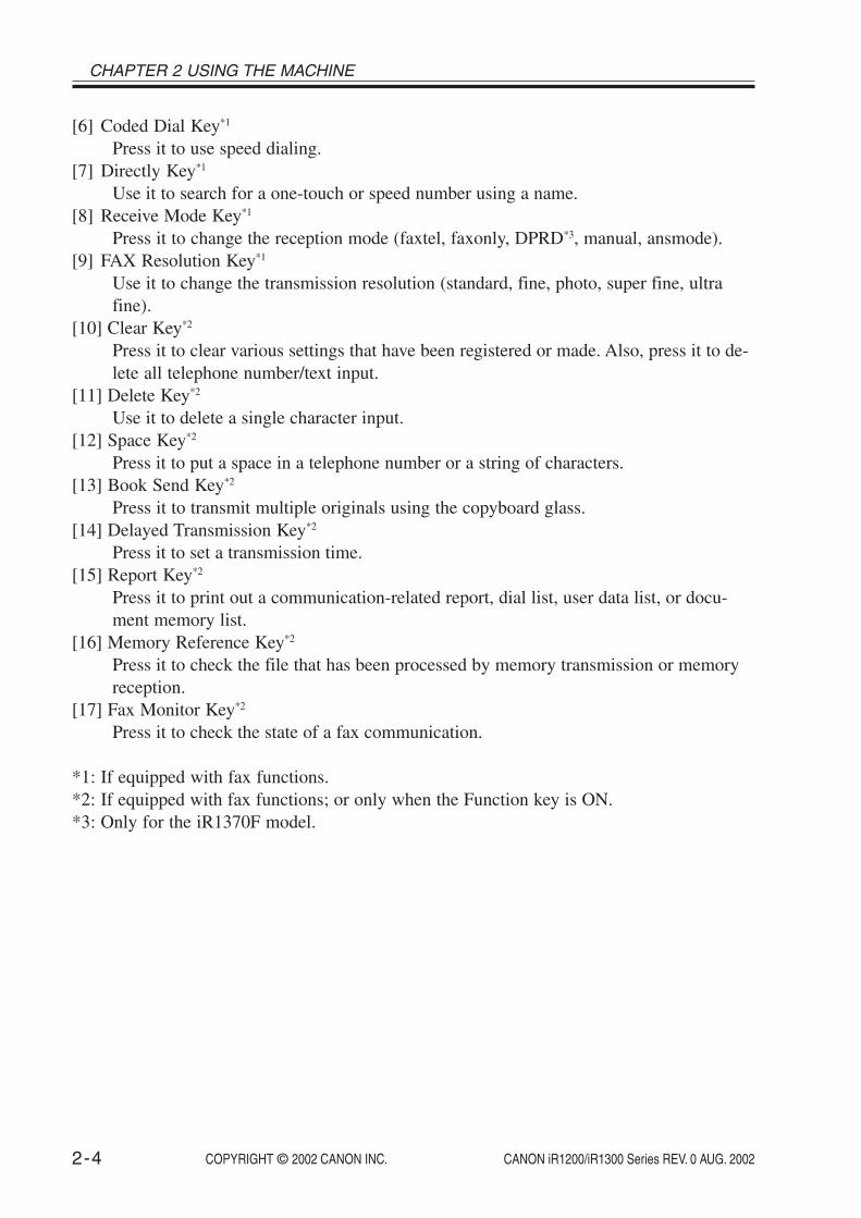
[6] Coded Dial Key*1
Press it to use speed dialing.[7] Directly Key*1
Use it to search for a one-touch or speed number using a name.[8] Receive Mode Key*1
Press it to change the reception mode (faxtel, faxonly, DPRD*3, manual, ansmode).[9] FAX Resolution Key*1
Use it to change the transmission resolution (standard, fine, photo, super fine, ultrafine).
[10] Clear Key*2
Press it to clear various settings that have been registered or made. Also, press it to de-lete all telephone number/text input.
[11] Delete Key*2
Use it to delete a single character input.[12] Space Key*2
Press it to put a space in a telephone number or a string of characters.[13] Book Send Key*2
Press it to transmit multiple originals using the copyboard glass.[14] Delayed Transmission Key*2
Press it to set a transmission time.[15] Report Key*2
Press it to print out a communication-related report, dial list, user data list, or docu-ment memory list.
[16] Memory Reference Key*2
Press it to check the file that has been processed by memory transmission or memoryreception.
[17] Fax Monitor Key*2
Press it to check the state of a fax communication.
*1: If equipped with fax functions.*2: If equipped with fax functions; or only when the Function key is ON.*3: Only for the iR1370F model.

COPYRIGHT © 2002 CANON INC. 2000 2000 2000 2000 CANON iR1200/iR1300 Series REV. 0 AUG. 2002 2-5
CHAPTER 2 USING THE MACHINE
2 User Mode
2.1 User Mode MenuA press on the Additional Functions key in the control panel brings up the user mode
menu. On the user mode menu, press the left/right arrow key to make menu settings or in-crease/decrease a value; press the OK key to store the selected input.
The user mode menu is constructed as follows:(The factory default setting is in bold face.)
1. COMMON SETTINGS
1.DEFAULT SETTINGS*1
COPYFAX
2.SW AFTER AUTO CLR*1
DEFAULT MODECURRENT MODE
3.VOLUME CONTROL*1
1.KEYPAD VOLUMEON
VOLUME1~3 (1)OFF
2.ALARM VOLUME*1
ONVOLUME1~3 (1)
OFF3.TX DONE TONE
ONVOLUME1~3 (1)
ERROR ONLYVOLUME1~3 (1)
OFF4.RX DONE TONE
ONVOLUME1~3 (1)
ERROR ONLYVOLUME1~3 (1)
OFF
*1: Only if equipped with fax functions.

CHAPTER 2 USING THE MACHINE
COPYRIGHT © 2002 CANON INC. 2000 2000 2000 2000 CANON iR1200/iR1300 Series REV. 0 AUG. 20022-6
1. COMMON SETTINGS
3.VOLUME CONTROL*1
5.PRINTING END TONEON
VOLUME1~3 (1)ERROR ONLY
VOLUME1~3 (1)OFF
6.SCANNING END TONEON
VOLUME1~3 (1)ERROR ONLY
VOLUME1~3 (1)OFF
7.CALLING VOLUME1~3 (2)
8.LINE MONITOR VOL.ON
VOLUME1~3 (2)OFF
4.STACK BYPASS SIZEOFF
BYPASS PAPER SIZEFREE SIZESET ON LOADING
ONBYPASS PAPER SIZE
A4*2
B5A5LGLLTR*3
STMTCUSTOM PAER SIZE
1.VERTICAL SIZE 76~216mm (216)2.HORIZONTAL SIZE 127~356mm (356)
*1: Only if equipped with fax functions.*2: Factory default for A/AB area.*3: Factory default for Inch area.

COPYRIGHT © 2002 CANON INC. 2000 2000 2000 2000 CANON iR1200/iR1300 Series REV. 0 AUG. 2002 2-7
CHAPTER 2 USING THE MACHINE
1. COMMON SETTINGS
5.DRAWER PAPER SIZEA4*1
LTR/LGL*2
B5FOLIOFOOLSCAP
6.PRINT EXPOSURE5 settings (Center)
7.MP PAPERTYPEPLAIN PAPERTRACING PAPERTRANSPARENCYSPECIAL PAPER 1SPECIAL PAPER 2
8.COPY POWER LEVELHIGHNORMALLOW
9.TONER SAVER MODEONOFF
10.PRT FEED INTERVALLONG INTERVALNORMAL INTERVAL
11.DISPLAY LANGUAGE*3
ENGLISHFRENCHSPANISHGERMANITALIANDUTCHFINNISHPORTUGUESENORWEGIANSWEDISHDANISHSLOVENECZECHHUNGARIANRUSSIAN
*1: Factory default for A/AB area.*2: Factory default for Inch area.*3: This setting may be unavailable depending on the value set for service mode #5 TYPE.

CHAPTER 2 USING THE MACHINE
COPYRIGHT © 2002 CANON INC. 2000 2000 2000 2000 CANON iR1200/iR1300 Series REV. 0 AUG. 20022-8
2. COPY SETTINGS
1.STD. IMAGEQUALITYTEXT ORIGINALTEXT/PHOTOPHOTO
2.STANDARD EXPOSUREAUTOMANUAL
9 settings (Center)3.STD ZOOM RATIO
50~200% (100%)4.STANDARD COPY QTY
01~99 (01)5.AUTO SORT
ONOFF
6.MAX. SCAN LENGTH330mm*1
356mm*2
7.PAPER SIZE GROUPINCH*2
A*3
AB*4
8. SHARPNESS1~9 (5)
*1: Factory default for A/AB area.*2: Factory default for Inch area.*3: Factory default for A area.*4: Factory default for AB area.

COPYRIGHT © 2002 CANON INC. 2000 2000 2000 2000 CANON iR1200/iR1300 Series REV. 0 AUG. 2002 2-9
CHAPTER 2 USING THE MACHINE
3.FAX SETTINGS*1
1.USER SETTINGS1.TEL LINE SETTINGS
1.USER TEL NO.2.TEL LINE TYPE
TOUCH TONEROTARY PULSE
3.TX START SPEED33600bps14400bps9600bps7200bps4800bps2400bps
4.RX START SPEED33600bps14400bps9600bps7200bps4800bps2400bps
2.UNIT NAME
*1: Only if equipped with fax functions.

CHAPTER 2 USING THE MACHINE
COPYRIGHT © 2002 CANON INC. 2000 2000 2000 2000 CANON iR1200/iR1300 Series REV. 0 AUG. 20022-10
3.FAX SETTINGS*1
1.USER SETTINGS3.TX TERMINAL ID
1.TTI POSITIONOUTSIDE IMAGEINSIDE IMAGE
2.TEL NUMBER MARKFAXTEL
4.DENSITY CONTROLLIGHTSTANDARDDARK
5.PROG. 1-TOUCH KEY01~12
USE1.REPORT2.DELAYED TX3.FAX MONITOR4.MEMORY REFERENCE5.BOOK SENDING
DO NOT USE6.OFFHOOK ALARM
ONOFF
7.R-KEY SETTING*2
PSTNPBX
HOOKINGEARTH CONNECTIONPREFIX
*1:Only if equipped with fax functions.*2:Only if equipped with fax functions and a 230V model.

COPYRIGHT © 2002 CANON INC. 2000 2000 2000 2000 CANON iR1200/iR1300 Series REV. 0 AUG. 2002 2-11
CHAPTER 2 USING THE MACHINE
3.FAX SETTINGS*1
2.REPORT SETTINGS1.TX REPORT
OUTPUT NOPRINT ERROR ONLY
REPORT WITH TX IMAGEONOFF
OUTPUT YESREPORT WITH TX IMAGE
ONOFF
2.RX REPORTOUTPUT NOPRINT ERROR ONLYOUTPUT YES
3.ACTIVITY REPORTONOFF
3.TX SETTINGS1.ECM TX
ONOFF
2.PAUSE TIME01~15SEC (02)
3.AUTO REDIALON
1.REDIAL TIMES01~10TIMES (02)
2.REDIAL INTERBAL02~99MIN. (02)
3.TX ERROR RESENDON
RESEND TX FROMERROR & 1ST PGERROR PAGEALL PAGES
OFFOFF
*1:Only if equipped with fax functions

CHAPTER 2 USING THE MACHINE
COPYRIGHT © 2002 CANON INC. 2000 2000 2000 2000 CANON iR1200/iR1300 Series REV. 0 AUG. 20022-12
3.FAX SETTINGS*1
3.TX SETTINGS4.ERASE FAILED TX
OFFON
5.TIME OUTONOFF
4.RX SETTINGS1.ECM RX
ONOFF
2.FAX/TEL OPT. SET1.RING START TIME
00~30SEC (08)2.F/T RING TIME
15~300SEC (15)3.F/T SWITCH ACTION
RECEIVEDISCONNECT
3.DRPD: SELECT FAX*2
NORMAL RINGDOUBLE RINGSHORT-SHORT-LONGSHORT-LONG-SHORTOTHER RING TYPE
4.INCOMING RINGOFFON
RING COUNT01~99TIMES (02)
5.MAN/AUTO SWITCHOFFON
F/T RING TIME01~99SEC (15)
6.REMOTE RXON
REMOTE RX ID00~99 (25)
OFF
*1: Only if equipped with fax functions.*2: Only for the iR1370F model.
COPYRIGHT © 2002 CANON INC. 2000 2000 2000 2000 CANON iR1200/iR1300 Series REV. 0 AUG. 2002 2-13
CHAPTER 2 USING THE MACHINE
3.FAX SETTINGS*1
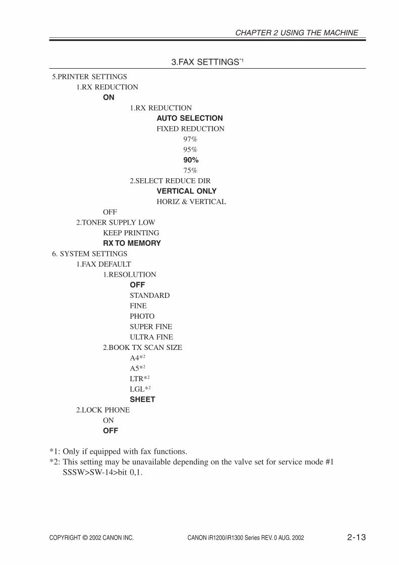
5.PRINTER SETTINGS1.RX REDUCTION
ON1.RX REDUCTION
AUTO SELECTIONFIXED REDUCTION
97%95%90%75%
2.SELECT REDUCE DIRVERTICAL ONLYHORIZ & VERTICAL
OFF2.TONER SUPPLY LOW
KEEP PRINTINGRX TO MEMORY
6. SYSTEM SETTINGS1.FAX DEFAULT
1.RESOLUTIONOFFSTANDARDFINEPHOTOSUPER FINEULTRA FINE
2.BOOK TX SCAN SIZEA4*2
A5*2
LTR*2
LGL*2
SHEET2.LOCK PHONE
ONOFF
*1: Only if equipped with fax functions.*2: This setting may be unavailable depending on the valve set for service mode #1
SSSW>SW-14>bit 0,1.

CHAPTER 2 USING THE MACHINE
COPYRIGHT © 2002 CANON INC. 2000 2000 2000 2000 CANON iR1200/iR1300 Series REV. 0 AUG. 20022-14
3.FAX SETTINGS*1
6.SYSTEM SETTINGS3.COUNTRY SELECT*2
UKGERMANYFRANCEITALYSPAINHOLLANDDENMARKNORWAYSWEDENFINLANDAUSTRIABELGIUMSWITZERLANDPORTUGALIRELANDGREECELUXEMBOURGHUNGARYCZECHRUSSIASLOVENIASOUTH AFRICAOTHERS
*1: Only if equipped with fax functions.*2: This setting may be unavailable depending on the value set for service mode #5 TYPE.

COPYRIGHT © 2002 CANON INC. 2000 2000 2000 2000 CANON iR1200/iR1300 Series REV. 0 AUG. 2002 2-15
CHAPTER 2 USING THE MACHINE
4.ADD. REGISTRATION*1
1.1-TOUCH SPD DIAL01~12
1.TEL NUMBER ENTRY2.NAME3.OPTIONAL SETTING
ON1.TX TIME SETTING
1~52.TX TYPE
REGULAR TXSUBADDRESS TX
1. PASSWORD2. SUBADDRESS
POLLING RX1. PASSWORD2. SUBADDRESS
OFF2.CODED SPD DIAL
*00~*991.TEL NUMBER ENTRY2.NAME3.OPTIONAL SETTING
ON1.TX TIME SETTING2.TX TYPE
REGULAR TXSUBADDRESS TX
1. PASSWORD2. SUBADDRESS
POLLING RX1. PASSWORD2. SUBADDRESS
OFF3.GROUP DIAL
01~121.TEL NUMBER ENTRY2.NAME3.TX TIME SETTING
1~5
*1: Only if equipped with fax functions.

CHAPTER 2 USING THE MACHINE
COPYRIGHT © 2002 CANON INC. 2000 2000 2000 2000 CANON iR1200/iR1300 Series REV. 0 AUG. 20022-16
5.TIMER SETTINGS
1.DATE/TIME SETTING2.AUTO CLEAR
ONAUTO CLEAR TIME
1~9MIN. (2)OFF
3.ENERGY SAVERON
ENERGY SVR TIME03~30MIN. (5)
OFF4.DAILY TIMER SET
1.SUN2.MON3.TUE4.WED5.THU6.FRI7.SAT
5.DATE SETUPYYYY MM/DDMM/DD YYYYDD/MM YYYY
6.ADJUST./CLEAN
1.ROLLER CLEANING2.CLEAN ADF ROLLER*1
3.RESTART PRINTER4.MIX TONER
*1: Only if equipped with ADF functions.
COPYRIGHT © 2002 CANON INC. 2000 2000 2000 2000 CANON iR1200/iR1300 Series REV. 0 AUG. 2002 2-17
CHAPTER 2 USING THE MACHINE
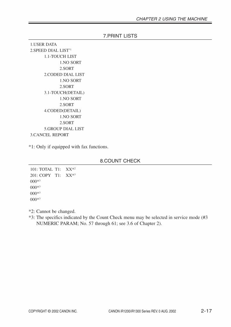
7.PRINT LISTS
1.USER DATA2.SPEED DIAL LIST*1
1.1-TOUCH LIST1.NO SORT2.SORT
2.CODED DIAL LIST1.NO SORT2.SORT
3.1-TOUCH(DETAIL)1.NO SORT2.SORT
4.CODED(DETAIL)1.NO SORT2.SORT
5.GROUP DIAL LIST3.CANCEL REPORT
*1: Only if equipped with fax functions.
8.COUNT CHECK
101: TOTAL T1: XX*2
201: COPY T1: XX*3
000*3
000*3
000*3
000*3
*2: Cannot be changed.*3: The specifics indicated by the Count Check menu may be selected in service mode (#3
NUMERIC PARAM; No. 57 through 61; see 3.6 of Chapter 2).

CHAPTER 2 USING THE MACHINE
COPYRIGHT © 2002 CANON INC. 2000 2000 2000 2000 CANON iR1200/iR1300 Series REV. 0 AUG. 20022-18
2.2 User Report2.2.1 Manually Generating a Report
The user can generate any of the following report manually:
Name of report
User data list1-touch spd dial list*1
1-touch dial spd dial list (detail)*1
Coded speed dial list*1
Coded speed dial list (detail)*1
Group dial list*1
Docement memory list*1
Activity report*1
Operation
Select a report in the user mode menu (2.1 ofChapter 2). Or, select fax mode. Press Functionkey and Report key in this order. Use the Left orRight Arrow key to select a list to print, thenpress OK key.
Select fax mode. Press Function key and Reportkey in this order. Use the Left or Right Arrowkey to select a list to print, then press OK key.
*1: Only if equipped with fax functions.T02-202-01
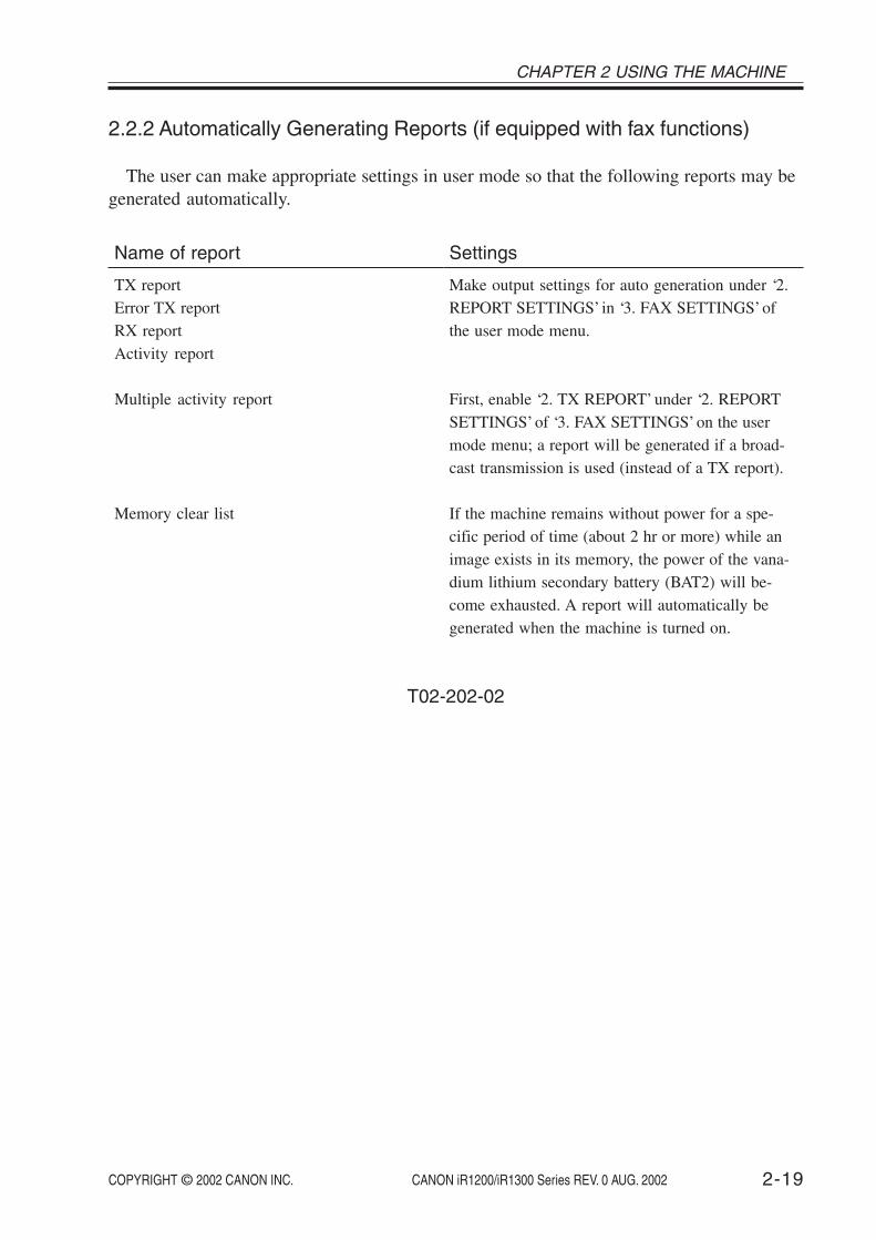
COPYRIGHT © 2002 CANON INC. 2000 2000 2000 2000 CANON iR1200/iR1300 Series REV. 0 AUG. 2002 2-19
CHAPTER 2 USING THE MACHINE
2.2.2 Automatically Generating Reports (if equipped with fax functions)
The user can make appropriate settings in user mode so that the following reports may begenerated automatically.
Name of report
TX reportError TX reportRX reportActivity report
Multiple activity report
Memory clear list
Settings
Make output settings for auto generation under ‘2.REPORT SETTINGS’ in ‘3. FAX SETTINGS’ ofthe user mode menu.
First, enable ‘2. TX REPORT’ under ‘2. REPORTSETTINGS’ of ‘3. FAX SETTINGS’ on the usermode menu; a report will be generated if a broad-cast transmission is used (instead of a TX report).
If the machine remains without power for a spe-cific period of time (about 2 hr or more) while animage exists in its memory, the power of the vana-dium lithium secondary battery (BAT2) will be-come exhausted. A report will automatically begenerated when the machine is turned on.
T02-202-02

CHAPTER 2 USING THE MACHINE
COPYRIGHT © 2002 CANON INC. 2000 2000 2000 2000 CANON iR1200/iR1300 Series REV. 0 AUG. 20022-20
2.2.2.1 Memory Clear List
0002000200020002
1111
DELAYED TXDELAYED TXMEMORY RXMEMORY RX
07/30 13:5107/30 13:5107/30 13:5307/30 13:54
13:5913:51----------
07/30/2001 17:52 FAX 001
MEMORY FILES DELETED
TX/RX NO MODE DESTINATION TEL/ID PGS. SET TIME ST. TIME
* * * * * * * * * * * * * * * * * * **
*
***
* *
*
*
***
*** * * * * * * * * * * * * * * * * * *
***
***
MEMORY CLEAR REPORT
TX/RX NO :MODE :DESTINATION TEL/ID :PGS. :SET TIME :ST. TIME :
F02-202-01
4-digit indicationtransmission, delayed transmission, or receptionone-touch dial/speed dial number, abbreviation of other partynumber of pages storeddate/time (in 24-hr notation)start of storage (in 24-hr notation)

COPYRIGHT © 2002 CANON INC. 2000 2000 2000 2000 CANON iR1200/iR1300 Series REV. 0 AUG. 2002 2-21
CHAPTER 2 USING THE MACHINE
3 Service Mode
3.1 Outline
The following items may be checked or set in the machine’s service mode, which consistsof those found in existing fax machines. You may use them as you would on a fax machine.
The machine’s service mode items are grouped into the following 15 blocks:
#1 SSSW: service soft switchUse it to register/set basic fax functions (e.g., error control, echo remedy, communica-tion error correction).
#2 MENU: menu switch settingsUse it to register/set items related to functions needed at time of installation (e.g., NLequalizer, transmission level).
#3 NUMERIC param: numerical parameter settingsUse it to enter a numerical parameter for various functions related to the FAX/TELswitch-over.
#4A SPECIAL: Do not change.
#4B NCU: Do not change.This item is set in conjunction with the setting of #5 TYPE so that the settings willcomply with the communications standards of a specific country/region.
#4C ISDN: not used
#5 TYPE: country/region settingUse it to select a country/region from the list so that the setting of #1 through #4 will comply with the communications standards of the selected country/region.
#6 SCANNER: partially available for serviceDo not change the settings except ‘7: CCD’, used to adjust the image position; other-wise, the read image quality can adversely be affected.
#7 PRINTER: printer function settingsUse it to register/set items related to printer basic service functions (e.g., conditions forreducing received images). Or, settings may also be made for humidity sensor fixed mode.
#8 PDL: not used
#9 COUNTER: counter informationUse it to check various counter information.

CHAPTER 2 USING THE MACHINE
COPYRIGHT © 2002 CANON INC. 2000 2000 2000 2000 CANON iR1200/iR1300 Series REV. 0 AUG. 20022-22
#10 REPORT: report outputUse it to generate a report on various service data.
#11 DOWNLOAD: not used
#12 CLEAR: data initialization mode settingUse it to initialize various data by selecting a specific item.
#13 ROM: ROM controlUse it to indicate information related to the ROM on the LCD (e.g., ROM version,checksum).
#14 CS SET: not used
TEST MODE: Use it to execute various testings.

COPYRIGHT © 2002 CANON INC. 2000 2000 2000 2000 CANON iR1200/iR1300 Series REV. 0 AUG. 2002 2-23
CHAPTER 2 USING THE MACHINE
3.2 Using Service Mode
1) Starting user mode menu. Press the Additional Functions key.
2) Selecting service mode menu. Press the # key on the user mode menu.
SERV I CE MODE
SERV I CE MODE
1 0 0 %
1.
TE XT
COMONN SE T T I NGS
3) Selecting a Menu Item. Press the Left or Right Arrow key.
4) Press the OK key.
5) Registering/Setting Data. Enter the data using the keypad, and press the OK key.
7) Press the Stop key/Additional Functions key to end service mode.
L TR0 1
REG I STRAT I ON / SET T I NG
SSSW# 1
# 3
# 3
# 3
# 3
P a r am.
NUMER I C
NUMER I C
P a r am.
NUMER I C P a r am.
NUMER I C P a r am.
0 0 1 :
0 0 1 :
0 0 2 :
0
10
10
6) Selecting a Menu Item. Press the Left or Right Arrow key.
F02-302-01

CHAPTER 2 USING THE MACHINE
COPYRIGHT © 2002 CANON INC. 2000 2000 2000 2000 CANON iR1200/iR1300 Series REV. 0 AUG. 20022-24
3.3 List of Service Mode Menus
#1 SSSW SW01 00010000SW02 00000000SW03 00000000SW04 10000000SW05 00000000SW06 10010000SW07 00000000SW08 00000000SW09 00000000SW10 00000000SW11 00000000SW12 00000010SW13 00000000SW14 00000001
SW15 00000000
SW24 00000000SW25 00000000SW26 00000000SW27 00000000SW28 00000000SW29 00000000SW30 00000000SW31 00000000SW32 00000000SW33 00000000SW34 00000000
SW50 00000000
service data
error/copy controlnetwork connection settingecho remedy settingcommunication fault remedy settingstandard function (DIS signal) settingread conditions settingnot usednot usednot usednot usednot used1-page timer settingnot usedby default paper type; metric/inch switch-overnot used
not usedreport indication function settingtransmission function settingnot usedV.8/V.34 protocol settingsnot usednot usednot usednot usedcounter relatednot used
not used
(service soft switch settings)
F02-303-01
Memo
To select the SW number in #1 SSSW, use Paper Select key and Enlarge/Reduce key. To select a bit, use the Left or Right Arrow key.
Do not change the following, reserved for the future; SW7 through 11, 13,15 through 24, 27, 29 through 32, 34 through 50.

COPYRIGHT © 2002 CANON INC. 2000 2000 2000 2000 CANON iR1200/iR1300 Series REV. 0 AUG. 2002 2-25
CHAPTER 2 USING THE MACHINE
#2 MENU 001: 002: 003: 004: 005:
006:
007:
008:
009:
010:
011:
020:
ONOFF
DIALSERVICEMAN [1]SERVICEMAN [2]OFF
0dBm1dBm2dBm
14dBm15dBm
342932003000280027432400
not usednot usednot usednot usedNL equalizer setting
line monitor setting
transmission level setting
V.34 baud rate
V.34 transmission speed
pseudo CI signal frequency setting
items 11 through 20: not used
(menu switch setting)
17Hz25Hz50Hz
33.631.228.826.424.021.619.216.814.412.09.67.24.82.4
F02-303-02
Do not change the following, reserved for the future: No. 01 through 04,11 through 20.

CHAPTER 2 USING THE MACHINE
COPYRIGHT © 2002 CANON INC. 2000 2000 2000 2000 CANON iR1200/iR1300 Series REV. 0 AUG. 20022-26
#3 NUMERIC Param. 001: 002:
003:
004:
005:
006:
007: 008: 009:
010: 011: 012: 013: 014: 015: 016:
017:
018:
019:
020:
021:
022:
023:
024:
025:
026: 027:
028:
029:
055:056:057:058:059:060:061:062:
080:
not usedRTM signal transmission condition (1) settingRTM signal transmission condition (2) settingRTM signal transmission (3) settingNCC pause time (pre-ID code) settingNCC pause time (post-ID code) settingnot usednot useddirect mail prevention function:telephone number cross-check,number of digitsT0 timerTS1 timernot usedT30 E0L timernot usedhooking detection time settingfax/tel switch-over function:between line acquisition and pseudo RBTtransmissionpseudo RBT signal pattern: ON time settingpseudo RBT signal pattern: OFF time (short) settingpseudo RBT signal pattern: OFF time (long) settingpseudo CI signal pattern: ON time settingpseudo CI signal pattern: OFF time (short) settingpseudo CI signal pattern: OFF time (long) settingnot used
pseudo RBT signal transmission level settinganswering phone connection function: signal monitor length settingnot usedV21 low-speed flag preamble detection length settingmenu pop-uptime settingnot used
not usedtotal 1 indicationcopy (total 1) indicationno indicationno indicationno indicationno indicationnot used
not used
(numerical parameter setting)
Initial setting
Range of setting
10 (10%) (1~99)
15 (15times) (2~99)
12 (12lines) (1~99)
100 (1000ms)(0~999)
0 (0ms) (0~999)
200 (2000ms)(0~999)
100 (1000ms)(0~999)
0 (0ms) (0~999)
200 (2000ms)(0~999)
20 (-20dBm) (0~20)
60 (60sec) (0~999)
6(6 digits) (0~20)
4 (4sec) (0~9)
5500 (55sec) (0~9999)3500 (35sec) (0~9999)
1300 (13sec) (500~3000)
120 (1200ms)(0~999)
4 (4sec) (0~60)
4 (4sec) (0~60)
3 (30ms) (0~99)
3 (3s)
1012010000
(0~60)
(101)(0~999)(0~999)(0~999)(0~999)(0~999)
F02-303-03

COPYRIGHT © 2002 CANON INC. 2000 2000 2000 2000 CANON iR1200/iR1300 Series REV. 0 AUG. 2002 2-27
CHAPTER 2 USING THE MACHINE
Do not use the following, reserved for the future: No. 001, 007, 008, 012,014, 023, 026, 029 through 055, 062 through 080.
#4B NCU
#4A SPECIAL
#4C ISDN
(NCU setting)
EUROPEU.K.SWEDENSWISSAUSTRIADENMARKNORWAYHOLLANDBELGUIMAUSTRALIAFINLANDN.Z.ITALYSPAINPORTUGALIRELANDHONG KONGMALAYSIAHUNGARYSAFKOREACHINAGERMANFRANCESINGAPORECZECHSLOVENIAASIAPOLANDTAIWANEUROPE2STANDARDUSA
#5 TYPE(type setting)
F02-303-04
#4A SPECIALDo not change the setting.
#4B NCU (NCU setting)The settings under this item are collectively and automatically set in conjunction with #5
TYPE to suit the communications standards of a specific country/region.Not used. (Do not change the setting.)

CHAPTER 2 USING THE MACHINE
COPYRIGHT © 2002 CANON INC. 2000 2000 2000 2000 CANON iR1200/iR1300 Series REV. 0 AUG. 20022-28
#4C ISDNNot used.
#5 TYPEUse it to select a specific country/region from the list so that the settings under #1 through
#4 will comply with the communications standards of the selected country/region.
When changing the TYPE setting, be sure not to select a country/regionwhich is not the country/region of installation.

COPYRIGHT © 2002 CANON INC. 2000 2000 2000 2000 CANON iR1200/iR1300 Series REV. 0 AUG. 2002 2-29
CHAPTER 2 USING THE MACHINE
#2 NUMERIC Param
#4 PRINTER RESET YES= (<)NO= (>)
#3 PRINT COUNT
#7 PRINTER(printer function setting)
SW01 00000000 SW01 through 05: not used
SW05 10000000SW06 00000100 reduction settingSW07 00000000 not used
SW12 00000000 not usedSW13 00000000 humidity sensor fixed modeSW14 00000000 not used
SW20 00000000 not used
SW07 through 12: not used
SW14 through 20: not used
#5 MLT CLEANING
#1 SSSW
#6 SCANNER(scanner function setting)
1. Bit SW2. SLICE3. GAMMA4. Numeric5. LUT 1 fno6. LUT 2 adj7. CCD8. MODEL
not used
F02-303-05
Memo
To select the SW number in #1 SSSW of #7 PRINTER, use Paper Select keyand Enlarge/Reduce key. To select a bit, use the Left or Right Arrow key.
#6 SCANNER (scanner function setting);The setting of this item can affect the read image quality. A change may bemade to ‘7. CCD’ when adjusting the image position; otherwise, do not usethis item.Do not change the settings, as they are not in use: #7 PRINTER (printerfunction setting); #1 SSSW: SW01 through 05, 07 through 12, 14 though20. Also, do not change the setting of ‘#2 NUMBER Param’.

CHAPTER 2 USING THE MACHINE
COPYRIGHT © 2002 CANON INC. 2000 2000 2000 2000 CANON iR1200/iR1300 Series REV. 0 AUG. 20022-30
service-use total counter 1 indication
service-use total counter 2 indication
total counter indication
total copy counter indication
print counter indication
fax reception print counter indication
report print counter indication
scan counter indication
cassette pickup counter indication
not used
not used
not used
manual feed tray pickup counter indication
ADF pickup counter indication
machine total jam counter indication
ADF jam counter indication
not used
manual feed tray jam counter indication
cassette jam counter indication
not used
not used
not used
not used
#8 PDL
#9 COUNTER SERVICE1
SERVICE2
TTL
COPY
PDL-PRT
FAX-PRT
RPT-PRT
SCAN
C1
C2
C3
C4
MF
FEED
TTL
FEEDER
SORTER
MF
C1
C2
C3
C4
TOTAL
PICK-UP
FEEDER
JAM
MISC
F02-303-06
#8 PDLNot used.

COPYRIGHT © 2002 CANON INC. 2000 2000 2000 2000 CANON iR1200/iR1300 Series REV. 0 AUG. 2002 2-31
CHAPTER 2 USING THE MACHINE
service mode data, start date, system dump list output, etc.
service mode data, start date output
system dump list output
recent key presses history (1800 presses) output
not used
counter output
specifications output
dial registration mode, user data initialization
user data initialization
SSSW data initialization
system dump list initialization
communications control report initialization
not used
not used
not used
counter initialization
not used
not used
total data initialization
image processor PCB ROM version indication
image processor PCB CPU version indication
DC controller PCB ROM version indication
printer controller PCB ROM version indication
#10 REPORT
#11 DOWNLOAD
#12 CLEAR
#13 ROM
#14 CS SET
TEST MODE [1] ~ [6], [8]
ACTIVITY
JAM
ERR
ALARM
1.SERVICE & SYSTEM
2.SERVICE DATA
3.SYSTEM DUMP
4.KEY HISTORY REPORT
5.BCH LOG REPORT
6.COUNTER REPORT
7.PRINT SPEC REPORT
TEL & USER DATA
USER DATA
SERVICE SW
SERVICE DATA
REPORT
COUNTER
CARD
ERR
ALL
MAIN
MAIN2
ECONT
PDL
F02-303-07
#11 DOWNLOADNot used.
#14 CS SETNot used.

CHAPTER 2 USING THE MACHINE
COPYRIGHT © 2002 CANON INC. 2000 2000 2000 2000 CANON iR1200/iR1300 Series REV. 0 AUG. 20022-32
3.4 Bit Switch Settings (#1 SSSW)A bit switch consists of 8 bits, used for registering/setting an item. The switch is config-
ured as follows, and each bit is always either ‘0’ or ‘1’:
SW01 0 0 0 0 0 0 0 0Bi
t 7Bi
t 6Bi
t 5Bi
t 4Bi
t 3Bi
t 2Bi
t 1Bi
t 0
F02-304-01
Do not change service data marked “not used” for its initial setting.
#SSSW-SW01: error/copy control
Bit
0
1
2
3
4
5
6
7
Function
service error code
error dump list
not used
not used
not used
not used
not used
user setting restriction
1
output
output
-
-
-
-
-
do not impose
0
do not output
do not output
-
-
-
-
-
impose
Factory setting
0
0
0
[Bit 0]Use it to specify whether or not to generate a service error code. If set to ‘1’, a service er-
ror code will be indicated on the report.
[Bit 1]Use it to specify whether or not to generate an error dump list. When set to ‘1’, an error
dump list will be attached to an error TX report or a RX report generated in the event of anerror.
[Bit 7]Use it to impose or not impose restrictions on user settings. If set to ‘0’, certain items can-
not be set by the user, depending on the country setting. If set to ‘1’, on the other hand, allitems may be set by the user, regardless of the country setting.

COPYRIGHT © 2002 CANON INC. 2000 2000 2000 2000 CANON iR1200/iR1300 Series REV. 0 AUG. 2002 2-33
CHAPTER 2 USING THE MACHINE
#SSSW-SW02: network connection conditions setting
Bit
0
1
2
3
4
5
6
7
Function
start-up at memory clear list out-put fault
not used
not used
not used
not used
not used
not used
not used
1
prohibit
-
-
-
-
-
-
-
0
do not prohibit
-
-
-
-
-
-
-
Factory setting
0
[Bit 0]Use it to specify whether or not to put the machine in standby state if the memory clear
list is not generated when the power is turned on after an error has occurred (e.g., runningout of paper).
If set to ‘1’, the machine will generate a memory clear list and enters standby state whenthe image data is cleared and the power is turned on.
If set to ‘1’, moreover, the following takes place:1. The alarm sounds, and the machine waits for correction; specifically,
a. The LCD indicates ‘CHECK PRINTER’.b. The machine will not start reception operation in response to arrival of data.
2. When an appropriate correction is made, the machine will automatically generate amemory clear list. If an error (e.g., jam) occurs during output, the machine goes back to1. above.
If set to ‘0’, on the other hand, the machine will sound the alarm and enters standby state.

CHAPTER 2 USING THE MACHINE
COPYRIGHT © 2002 CANON INC. 2000 2000 2000 2000 CANON iR1200/iR1300 Series REV. 0 AUG. 20022-34
Bit
0
1
2
3
4
5
6
7
Function
not used
echo product tone in high-speedtransmission
not used
not used
Transmission mode; longdistance (1)
Transmission mode; longdistance (2) or long distance (3)
Transmission mode
tonal signal before transmissionof CED signal
1
-
transmit
-
-
Yes
Yes
Longdistance (3)
transmit
0
-
do not transmit
-
-
No
No
Longdistance (2)
do not transmit
Factory setting
0
0
0
0
0
0
[Bit 1]Use it to specify whether or not to transmit an echo protection tone for high-speed trans-
mission V.29 (9600 or 7200 bps; modem signal).If an error occurs often because of a line condition at time of transmission, set it to ‘1’. If
set to ‘1’, unmodulated carrier will be transmitted as a sync signal before transmission of animage for about 200 msec.
Memo
The following error codes are associated with a line condition at time oftransmission:##100, ##104, ##281, ##282, ##283, ##750, ##755, ##760, ##765
[Bit 7]Use it to specify whether or not to transmit a 1080-Hz tonal signal before transmission of
the CED signal. Set it to ‘1’ if an error occurs often because of an error at time of reception.
Memo
The following error codes are associated with an echo at time of reception:##005, ##101, ##106, ##107, ##114, ##200, ##201, ##790
#1 SSW-SW03: echo remedy setting

COPYRIGHT © 2002 CANON INC. 2000 2000 2000 2000 CANON iR1200/iR1300 Series REV. 0 AUG. 2002 2-35
CHAPTER 2 USING THE MACHINE
[Bit 4, 5, 6]Select the transmission mode, long distance (1), long distance (2), or long distance (3). If
errors due to echo occur frequently in transmission to overseas, set the transmission modewith the dial registration or service soft switch.
Memo
Codes for errors that can occur during transmission because of echo:##005, ##100, ##101, ##102, ##104, ##201, ##280, ##281, ##283, ##284,##750, ##760, ##765, ##774, ##779, ##784, ##794
TEL registration:Set “Long distance (1)” when registering the one-touch speed dialing and coded speed
dialing transmission mode. If errors do not disappear, try “Long distance (2)” and “Longdistance (3)”.
The transmission mode set in one-touch speed dialing and coded speed dialing registra-tion takes priority over the one set with the service soft switch.
These bit switches are applicable to manually dialed numbers only. Look at the followingtable and set “Long distance (1)”. If errors persist, try “Long distance (2)” or “Long distance(3)”.
BitTX mode 7 6 5 4 3 2 1 0Long distance (1) * 0 0 1 0 0 * 0Long distance (2) * 0 1 0 0 0 * 0Long distance (3) * 1 1 0 0 0 * 0
* : 0 or 1 (depending on the respective setting)
Long distance (1) ignores the first DIS signal sent by the other fax.Long distance (2) sends an 1850-Hz tonal signal when the DIS signal is transmitted.Long distance (3) sends a 1650-Hz tonal signal when the DIS signal is transmitted.

CHAPTER 2 USING THE MACHINE
COPYRIGHT © 2002 CANON INC. 2000 2000 2000 2000 CANON iR1200/iR1300 Series REV. 0 AUG. 20022-36
#1 SSSW-SW04: communication fault remedy setting
Bit
0
1
2
3
4
5
6
7
Function
Monitor loop current
Check CI frequency
number of last flag sequence forprocedure signal
reception mode after transmis-sion of CFR signal
length of time during which toignore low-speed signal aftertransmission of CFFR signal
not used
not used
CED signal at time of manualreception
1
Yes
Yes
2
high-speed
1500ms
-
-
do not transmit
0
No
No
1
high-speed/low-speed
700ms
-
-
transmit
Factory setting
0
0
0
0
0
1
[Bit 0]Selects whether or not to monitor loop current. When ‘Yes’ is selected, if loop current
cannot be detected before dialing, or if the loop current is cut during or transmission, theline is released.
[Bit 1]In automatic recieving, CI frequency check can be selected. If ‘Yes’ is selected, the upper
and lower limits of the CI frequency are checked, and automatic recieving can only goahead if both values meet German regulations.
[Bit 2]Use it to specify the number of last flag sequences for the procedure signal (300 bps). Se-
lect ‘2’ if the other party fails to receive the procedure signal transmitted by the machinenormally.
Memo
The following error code are associated with transmission:##100, ##280, ##281, ##750, ##753, ##754, ##755, ##758, ##759, ##760,##763, ##764, ##765, ##768, ##769, ##770, ##773, ##775, ##778, ##780,##783, ##785, ##788,
[Bit 3]Use it to select reception to use after transmission of the CFR signal.If an error occurs often because of the line condition at time of reception, set it to ‘1’ and,
at the same time, set ‘ECM RX’ to ‘OFF’ for user data.

COPYRIGHT © 2002 CANON INC. 2000 2000 2000 2000 CANON iR1200/iR1300 Series REV. 0 AUG. 2002 2-37
CHAPTER 2 USING THE MACHINE
Memo
The following error codes are associated with the line condition at time ofreception:##107, ##114, ##201Be sure to change bit 4 before changing this bit; resort to this bit only if anerror still occurs.When set to ‘1’, only high-speed (image) signals will be received after thetransmission of the CFR signal.
[Bit 4]Use it to select the length of time during which low-speed signals are ignored after trans-
mission of the CFR signal.Select ‘1500 msec’ if reception of image signals is not good because of a poor line condi-
tion.
[Bit 7]Use it to specify whether or not to send the CED signal at time of manual reception.Set it to ‘transmit’ if the other party does not start transmission when manual reception is
initiated.
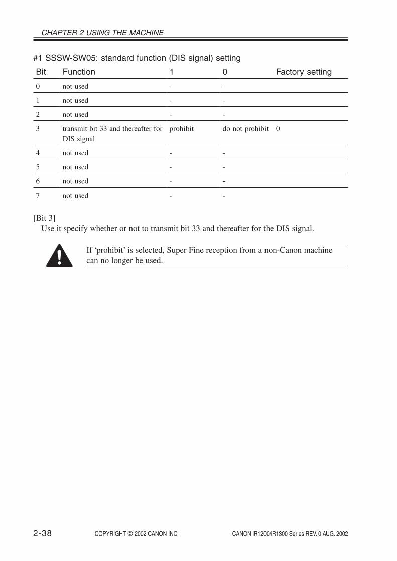
CHAPTER 2 USING THE MACHINE
COPYRIGHT © 2002 CANON INC. 2000 2000 2000 2000 CANON iR1200/iR1300 Series REV. 0 AUG. 20022-38
#1 SSSW-SW05: standard function (DIS signal) setting
Bit
0
1
2
3
4
5
6
7
Function
not used
not used
not used
transmit bit 33 and thereafter forDIS signal
not used
not used
not used
not used
1
-
-
-
prohibit
-
-
-
-
0
-
-
-
do not prohibit
-
-
-
-
Factory setting
0
[Bit 3]Use it specify whether or not to transmit bit 33 and thereafter for the DIS signal.
If ‘prohibit’ is selected, Super Fine reception from a non-Canon machinecan no longer be used.

COPYRIGHT © 2002 CANON INC. 2000 2000 2000 2000 CANON iR1200/iR1300 Series REV. 0 AUG. 2002 2-39
CHAPTER 2 USING THE MACHINE
#1 SSSW-SW06: read condition setting
Bit
0
1
2
3
4
5
6
7
Function
not used
not used
not used
not used
original read width
not used
not used
not used
1
-
-
-
-
LTR
-
-
-
0
-
-
-
-
A4
-
-
-
Factory setting
1
[Bit 4]Use it to select a read width for originals.If ‘LTR’ is selected, the machine will read LTR originals at LTR width (212 mm).

CHAPTER 2 USING THE MACHINE
COPYRIGHT © 2002 CANON INC. 2000 2000 2000 2000 CANON iR1200/iR1300 Series REV. 0 AUG. 20022-40
#1 SSSW-SW12: page timer setting
Bit
0
1
2
3
4
5
6
7
Function
1-page time-out length for trans-
mission/reception
1-page time-out length for trans-
mission (HT transmission)
1-page time-out length for re-
ception
not used
page timer setting by transmis-
sion/reception
1
1
1
1
1
1
1
-
set
0
0
0
0
0
0
0
-
do not set
Factory setting
0
1
0
0
0
0
0
The machine is designed to stop communication when transmission/reception of a singlepage takes 32 min or more. To set a time-out length, refer to the next page.
If ‘1’ is selected for bit 7, the 1-page time-out length will be as set by bit 0 and bit 1.

COPYRIGHT © 2002 CANON INC. 2000 2000 2000 2000 CANON iR1200/iR1300 Series REV. 0 AUG. 2002 2-41
CHAPTER 2 USING THE MACHINE
Time-Out Length for Transmission/Reception
Bittime-out length
8 min16 min32 min64 min
7
0000
6
****
5
****
4
****
3
****
2
****
1
0011
0
0101
Bittime-out length
8 min16 min32 min64 min
7
1111
6
****
5
****
4
****
3
****
2
****
1
0011
0
0101
Bittime-out length
8 min16 min32 min64 min
7
1111
6
****
5
0011
4
0101
3
****
2
****
1
****
0
****
Bittime-out length
8 min16 min32 min64 min
7
1111
6
****
5
****
4
****
3
0011
2
0101
1
****
0
****
Time-Out Length for Transmission (text mode)
Time-Out Length for Transmission (image mode other than text mode)
Time-Out Length for Reception

CHAPTER 2 USING THE MACHINE
COPYRIGHT © 2002 CANON INC. 2000 2000 2000 2000 CANON iR1200/iR1300 Series REV. 0 AUG. 20022-42
#1 SSSW-SW14: inch/meter resolution setting
Bit
0
1
2
3
4
5
6
7
Function
paper size identification
paper size identification
inch/meter resolution conversionscanning direction
not used
declare inch resolution
not used
not used
not used
1
1
1
main/sub scan-ning
-
declare
-
-
-
0
0
0
sub scanningonly
-
do not declare
-
-
-
Factory setting
0
0
1
0
[Bit 0, 1]Use a combination of bit 0 and bit 1 to set the size of paper (default side).• if 0 and 0, A/B-configured paper.• if 0 and 1, inch-configured paper• if 1 and 0, A-configured paper• if 1 and 1, A/B-configured paper
[Bit 2]Use it to specify whether to convert an inch resolution into a metric resolution for images
read at time of G3 transmission only in sub scanning direction or in both main and sub scan-ning direction.
The setting made here is effective only if bit 1 of SW05 of #1 SSSW is set to ‘1’.
[Bit 4]Use it to specify whether or not to declare an inch resolution to the other party at time of
G3 communication.If set to ‘1’, a declaration will be made using the DIS, DCS, or DTC signal to the effect
that the machine is designed to read and record images at an inch resolution.
Memo
The type of image and the direction of scanning for inch/meter resolutionconversion are determined by combinations of bits 1 and 2 of SW05 and bit2 of SW14 of #1 SSSW as well as the type of dialing used.

COPYRIGHT © 2002 CANON INC. 2000 2000 2000 2000 CANON iR1200/iR1300 Series REV. 0 AUG. 2002 2-43
CHAPTER 2 USING THE MACHINE
• When One-Touch Dial/Coded Dial and Keypad/Redial Key Is in Use
bit1
0000
1
1
1
1
bit2
0011
0
0
1
1
bit2
0101
0
1
0
1
bit3
----
-
-
-
-
Image and scanning direction subject to inch/meter conversion
do not execute inch/meter conversion
text image/sub scanning
text image/main scanning and sub scanning
text and photo image/sub scanning
text and photo image/main and sub scanning
SW05 SW14

CHAPTER 2 USING THE MACHINE
COPYRIGHT © 2002 CANON INC. 2000 2000 2000 2000 CANON iR1200/iR1300 Series REV. 0 AUG. 20022-44
#1 SSSW-SW25: report indication function setting
Bit
0
1
2
3
4
5
6
7
1
number ofother party
-
-
-
-
-
-
-
0
number ofcaller
-
-
-
-
-
-
-
Factory setting
0
Function
transmission telephone numberindicated on report
not used
not used
not used
not used
not used
not used
not used
[Bit 0]Use it to select the number to be indicated on the report, generated at the end of transmis-
sion.Number of caller: Select it to indicate the telephone number of the caller on the re-
port.Number of other party: Select it to indicate the telephone number sent by the other party
(CSI signal data).
Memo
If a change is made using a means other than one-touch dialing or speed di-aling, the telephone number sent by the other party (CSI signal data) will beindicated on the report even when ‘number of caller’ is selected.

COPYRIGHT © 2002 CANON INC. 2000 2000 2000 2000 CANON iR1200/iR1300 Series REV. 0 AUG. 2002 2-45
CHAPTER 2 USING THE MACHINE
#1 SSSW-S26: transmission function setting
Bit
0
1
2
3
4
5
6
7
Function
not used
not used
broadcast transmission confir-mation
broadcast transmission prohibi-tion
not used
not used
other party at time of broadcasttransmission suspension
error TX report at time of trans-mission suspension
1
-
-
ask
ask
-
-
single party
do not generate
0
-
-
do not ask
do not ask
-
-
all parties
generate
Factory setting
0
0
0
0
[Bit 2]Use it to specify whether or not to indicate a confirm message to prevent the user from
making a broadcast by mistake when entering an address for a broadcast transmission.
[Bit 3]Use it to specify whether or not to use broadcast transmission to prevent the user from
making a broadcast by mistake when entering an address for a broadcast transmission.
[Bit 6]Use it to specify whether or not to suspend a communication to all parties when a broad-
cast transmission is suspended.
[Bit 7]Use it to specify whether or not to generate an error TX report when a transmission is sus-
pended by pressing the Stop key.

CHAPTER 2 USING THE MACHINE
COPYRIGHT © 2002 CANON INC. 2000 2000 2000 2000 CANON iR1200/iR1300 Series REV. 0 AUG. 20022-46
#1 SSSW-SW28: V.8/ V.34 protocol settings
Bit01234
5
67
FunctionCaller V.8 protocolCalled party V.8 protocolCaller V.8 protocol late startCalled party V.8 protocol late startV.34 reception fallback
V.34 transmission fallback
not usednot used
1NoNoNoNoProhibited
Prohibited
--
0YesYesYesYesNotprohibitedNotprohibited--
Factory setting00000
0
[Bit 0]Select whether to use the V.8 protocol when calling. If NO is selected, the V.8 protocol isinhibited at calling and the V.21 protocol is used.
[Bit 1]Select whether to use the V.8 protocol when called. If NO is selected, the V8 protocol is in-hibited when called and the V.21 protocol is used.
[Bit 2]If ANSam signal is not received during transmission (mainly manual transmission), selectwhether to use the V.8 protocol when the other fax machine declares the V.8 protocol in DISsignal. If NO is selected, the CI signal is not transmitted and the V.8 protocol is not usedeven if the DIS that specifies the V.8 protocol is received.
[Bit 3]Select whether to declare the V.8 protocol in DIS signal for reception (mainly caller manualtransmission). If NO is selected, the V.8 protocol cannot be used because it is not declared inDIS signal.
[Bit 4]Select whether the receiver falls back during V.34 reception. If “Prohibit” is selected, the re-ceiver does not fall back.
[Bit 5]Select whether the transmitter falls beck during V.34 transmission. If “Prohibit” is selected,the transmitter does not fall back.

COPYRIGHT © 2002 CANON INC. 2000 2000 2000 2000 CANON iR1200/iR1300 Series REV. 0 AUG. 2002 2-47
CHAPTER 2 USING THE MACHINE
#1 SSSW-SW33:counter-related
Bit01234567
Functionnot usedindicate serial No. on counter check screennot usednot usednot usednot usednot usednot used
1-No------
0-Yes------
Factory setting
0
[Bit 1]Use it to specific whether to indicate the machine serial No. on the Counter Check screen,appearing when the Counter key is pressed.If ‘yes’ is selected, the serial No. will be indicated. If ‘no’ is selected, on the other hand, theserial No. will not be indicated.

CHAPTER 2 USING THE MACHINE
COPYRIGHT © 2002 CANON INC. 2000 2000 2000 2000 CANON iR1200/iR1300 Series REV. 0 AUG. 20022-48
3.5 Menu Switch Settings (#2 MENU)
No.
005
006
007
008
009
010
Item
NL equalizer
telephone line monitor
transmission level (ATT)
V.34 modulation speed upper limit
V.34 data speed upper limit
pseudo CI signal frequency
Selection
ON, OFF
DIAL/SERVICEMAN[1]/SERVICEMAN[2]/OFF
0 through 15 (ex:15=-15dBm)
3429, 3200, 3000, 2800, 2743, 2400
from 2.4 to 33.6 kbps
50Hz, 25Hz, 17Hz
Initial setting
OFF
DIAL
10
3429
33.6
25Hz
005 NL equalizerUse it to turn on/off the NL equalizer.Turn on the NL equalizer if an error occurs often because of the line condition at time of
communication.
Memo
The following error codes are associated with the line condition at time oftransmission.##100, ##101, ##102, ##104, ##201, ##281, ##282, ##283, ##750, ##755,##765, ##774, ##779, ##784, ##789The following error codes are associated with the line condition at time ofreception##103, ##107, ##114, ##201, ##790, ##793
006 telephone line monitorUse it to set telephone line motor functions:
DIAL: Select it to generate a monitor sound for the telephone line fromthe start of transmission to DIS.
SERVICEMAN [1]: Select it to generate a monitor sound of the telephone line fromthe start of a communication to its end.
SERVICEMAN [2]: not usedOFF: Select it to mute the monitor sound for the telephone line for the
speaker.

COPYRIGHT © 2002 CANON INC. 2000 2000 2000 2000 CANON iR1200/iR1300 Series REV. 0 AUG. 2002 2-49
CHAPTER 2 USING THE MACHINE
007 ATT transmission levelUse it to set the transmission level (ATT).Increase the transmission level if an error occurs often because of the line condition at
time of a communication.
Memo
The following error codes are associated with the line condition at time oftransmission:##100, ##101, ##102, ##104, ##201, ##280, ##281, ##282, ##283, ##284,##750, ##752, ##754, ##755, ##757, ##759, ##760, ##762, ##764, ##765,##767, ##769, ##770, ##772, ##774, ##775, ##777, ##779, ##780, ##782,##784, ##785, ##787, ##789The following error codes are associated with the line condition at time ofreception:##103, ##106, ##107, ##201, ##793
008 V.34 modulation speed upper limitUse it to set an upper limit to the modulation speed (baud rate) for the V.34 primary chan-
nel.
009 V.34 data speed upper limitUse it to set an upper limit to the data transmission speed for the V.34 primary channel
between 2.4K and 33.6K bps in increments of 2400 bps. (0: 2.4K to 13: 33.6K bps).
010 pseudo CI signalUse it to set a frequency for the pseudo CI signal.
At times, certain types of external telephones fail to ring while fax/tel switch-over takesplace. If so, change the frequency of the pseudo CI signal.

CHAPTER 2 USING THE MACHINE
COPYRIGHT © 2002 CANON INC. 2000 2000 2000 2000 CANON iR1200/iR1300 Series REV. 0 AUG. 20022-50
3.6 Numeric Parameter Setting (#3 NUMERIC Param.)No.
02
03
04
05
06
09
10
11
13
15
16
17
18
19
20
21
22
24
25
27
28
56
57
58
59
60
61
Item
RTN transmission condition (1)
RTN transmission condition (2)
RTN transmission condition (3)
NCC pause length (pre-ID code)
NCC pause length (post-ID code)
number of digits of telephone numbers incomparison between transmitting and receiv-ing machine
line connection identification time length
T.30 T1 timer (for reception)
T30.EOL timer
hooking detection time length
time to tentative response at time of fax/telswitch-over
pseudo RBT signal pattern ON length
pseudo RBT signal pattern OFF time length(short)
pseudo RBT signal pattern OFF time length(long)
pseudo CI signal pattern ON time length
pseudo CI signal pattern OFF time length(short)
pseudo CI signal pattern OFF time length(long)
fax/tel switch-over pseudo RBT transmissionlevel
answer telephone CNG motor time length
V.21 low-speed flag preamble detection timelength
menu selection screen display time length
count type select 1
count type select 2
count type select 3
count type select 4
count type select 5
count type select 6
Range of settings
1 to 99%
2 to 99 times
1 to 99 lines
0 to 60 sec
0 to 60 sec
0 to 20 digits
0 to 9999 (10ms)
0 to 9999 (10ms)
500 to 3000 (10ms)
0 to 999 (10ms)
0 to 9 sec
0 to 999 (10ms)
0 to 999 (10ms)
0 to 999 (10ms)
0 to 999 (10ms)
0 to 999 (10ms)
0 to 999 (10ms)
0 to 20 dBm
0 to 999 sec
1 to 99 (10ms)
1 to 60 sec
101
0 to 999
0 to 999
0 to 999
0 to 999
0 to 999
Initial setting
10
15
12
4
4
6
5500
3500
1300
120
4
100
0
200
100
0
200
20
60
3
3
101
201
0
0
0
0

COPYRIGHT © 2002 CANON INC. 2000 2000 2000 2000 CANON iR1200/iR1300 Series REV. 0 AUG. 2002 2-51
CHAPTER 2 USING THE MACHINE
[No. 02. 03, 04]Use it to set conditions for RTN signal transmission. If an error occurs often when the
RTN signal is transmitted at time of reception, increase the parameters to loosen the RTNsignal transmission conditions.
Memo
The following error codes are associated with the transmission of the RTNsignal at time of reception:##104, ##107, ##114, ##201The RTN signal transmission condition (1) is the ratio of the number of er-ror lines in relation to the total number of lines per page of reception im-ages.The RTN signal transmission condition (2) is the reference value*2 for bursterrors*1.The RTN signal transmission condition (3) is the number of errors notreaching the reference value for burst errors.*1: transmission errors spanning several lines.*2: If set to ‘15’, a transmission error spanning 5 consecutive lines is
identified as a burst error.If any of these conditions is detected while an image signal is being revised,the RTN signal will be transmitted after receiving the procedure signal fromthe transmitting machine. A higher parameter will make the transmission ofthe RTN signal more difficult.
[No. 05]Use it to set the length of item (pause) automatically put between the access code an the
ID code when a number is dialed on an NCC (new common carrier) line.
[No. 06]Use it to set the length of time (pause) automatically put between the ID code and the
telephone number of the other party when a number is dialed on an NCC (new common car-rier) line.
[No. 09]Use it to set the number of TSI comparison digits (last XX digits) for a telephone number
cross check.
[No. 10]Use it to set the length of time for line connection identification. If an error occurs often
because of the line condition at time of a communication, increase the parameter.

CHAPTER 2 USING THE MACHINE
COPYRIGHT © 2002 CANON INC. 2000 2000 2000 2000 CANON iR1200/iR1300 Series REV. 0 AUG. 20022-52
Memo
The line condition detection time length refers to the length between whenthe dial signal is transmitted and when the line condition is cut in relation tothe transmitting side, while it is the length between when the DIS signal istransmitted and when the line is cut in relation to the receiving side.
[No. 11]The setting of the T1 timer varies from country to country (PTT). The T1 timer is vari-
able.
[No. 13]If the length of data for a single line is too long (e.g., computer fax), increase the 1-line
transmission time for possible reception to prevent a reception error.
[No. 15]Use it to set the hooking detection time.
[No. 16]Use it to set the time length between when the line is acquired and when the pseudo RBT
is transmitted when making a fax/tel switch-over.
[No. 17, 18, 19]Use it to set a pattern of the pseudo RBT signal transmitted when making a fax/tel switch-
over.
[NO. 20, 21, 22]Use it to set the pattern of the pseudo CI signal transmitted when making a fax/tel switch-
over.
[No. 24]Use it to set the pseudo RBT transmission level used when making a fax/tel switch-over.
[No. 25]Use it to set the length of time during which the absence of sound on the line, 2nd NSS
signal, or CNG signal transmitted by the other party is monitored after the answering phoneacquires the telephone line when answering machine mode is selected.
[No. 27]Use it to change the detection evaluation time. (Command analysis is started when the
V.21 low-speed command preamble is detected continuously for a specific period of time.)
[No. 28]Use it to set the length of time during which the Menu Select screen is indicated on the
LCD.

COPYRIGHT © 2002 CANON INC. 2000 2000 2000 2000 CANON iR1200/iR1300 Series REV. 0 AUG. 2002 2-53
CHAPTER 2 USING THE MACHINE
[No. 56 through 61]Use it to confirm the count type indicated on the Counter Check screen, which appears in
response to a press on the Counter key.When ‘0’ is selected, count type will not be indicated.No. 56 : fix to total 1 (101) for the counter 1 reading.No. 57 : use it to select a count type for the counter 2 reading.No. 58 : use it to select a count type for the counter 3 reading.No. 59 : use it to select a count type for the counter 4 reading.No. 60 : use it to select a count type for the counter 5 reading.No. 61 : use it to select a count type for the counter 6 reading.If above selections have been made, the counters will be displayed in order of counter
numbers.
<Soft Counter Specifications>The soft counters are classified as follows according to input numbers:101 : total102 : not used103 : not used104 : not used201 : copy202 : not used203 : not used204 : not used301 : print (indicates sum of prints from PC and report prints)302 : not used303 : not used304 : not used331 : PDL (indicates prints from PC only)332 : not used333 : not used334 : not used505 : scan506 : not used507 : not used508 : not used701 : received print702 : not used703 : not used704 : not used801 : report print802 : not used803 : not used804 : not used

CHAPTER 2 USING THE MACHINE
COPYRIGHT © 2002 CANON INC. 2000 2000 2000 2000 CANON iR1200/iR1300 Series REV. 0 AUG. 20022-54
Setting
total total 1 101copy total 1 201print total 1 301PDL total 1 331received print
total 1 701report print
total 1 801scan total 1 505
Basic counterCopy
√√
PDL print√
√√
Received print√
√
Report print√
√
√
Scan
√
Guide to the Table√ : available for the machine.
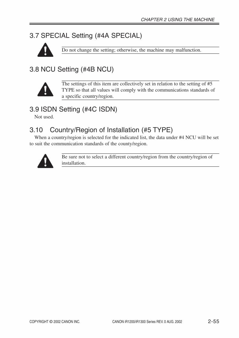
COPYRIGHT © 2002 CANON INC. 2000 2000 2000 2000 CANON iR1200/iR1300 Series REV. 0 AUG. 2002 2-55
CHAPTER 2 USING THE MACHINE
3.7 SPECIAL Setting (#4A SPECIAL)
Do not change the setting; otherwise, the machine may malfunction.
3.8 NCU Setting (#4B NCU)
The settings of this item are collectively set in relation to the setting of #5TYPE so that all values will comply with the communications standards ofa specific country/region.
3.9 ISDN Setting (#4C ISDN)Not used.
3.10 Country/Region of Installation (#5 TYPE)When a country/region is selected for the indicated list, the data under #4 NCU will be set
to suit the communication standards of the county/region.
Be sure not to select a different country/region from the country/region ofinstallation.

CHAPTER 2 USING THE MACHINE
COPYRIGHT © 2002 CANON INC. 2000 2000 2000 2000 CANON iR1200/iR1300 Series REV. 0 AUG. 20022-56
3.11 Setting the Original Reading Functions (#6 SCANNER)
7. CCD Settings
No.
1 to 18
19
21
23
24
25
26 to 33
34
Item
1.Bit SW2. SLICE3. GAMMA4. Numeric5. LUT 1 fno6. LUT 2 adj
7. CCD
8. MODEL
Description
Do not change the setting; otherwise, the read image quality can be lost.
partially hanged
not used
Item
Do not change.
shading position adjustment*1
left/right edge read start position adjustment(book mode)
leading edge read start position adjustment(book mode)
leading edge read start position(ADF mode)
trailing edge read end position adjustment(ADF mode)
Do not change.
original feed speed adjustment(ADF mode)
Unit of adjustment
-
(*2)
1 unit = approx. 0.03 mm
1 unit = 0.1 mm
1 unit = 0.1 mm
1 unit = 0.1 mm
-
1 unit = approx. 0.5 mm
*1: Make adjustments only When white lines occur. (See 3.1.12 of Chapter 7.)*2: 1 of the 4 shading levels is selected by inputting a number from 0 to 3.
(In the case of being imputed a number over 4, the shading level is equal to that selected0.)
The factory settings of these adjustments differ from machine to machine. For instructionson adjustment, see 1.2.4 of Chapter 7 or 1.3.4 of Chapter 7.

COPYRIGHT © 2002 CANON INC. 2000 2000 2000 2000 CANON iR1200/iR1300 Series REV. 0 AUG. 2002 2-57
CHAPTER 2 USING THE MACHINE
3.12 Setting the Printer Parameters (#7 PRINTER)3.12.1 #1 SSSW Setting
#7 PRINTER-#1 SSSW-SW06 (reduction setting)
Bit
0
1
2
3
4
5
6
7
Function
reduction at time of image divi-sion
not used
not used
not used
not used
not used
not used
not used
1
prohibit
-
-
-
-
-
-
-
0
do not prohibit
-
-
-
-
-
-
-
Factory setting
0
[bit 0]Use it to specify whether or not to reduce the received image of an extra-long original if it
can be printed in divisions after reducing to the maximum reduction ratio (70%).
prohibit:select it to divide and print on the next page (Direct).For instance, if an extra-length original as long as 2.5 A4R original is received, it will bedivided into 3 A4R sheets for printing; the image will be in Direct.
do not prohibit:select it to print the image by reducing it to fit a single page (in divided print mode).For instance, if an extra-length original as long as 2.5 A4R originals is received, it willbe reduced to 70% to print on 2 A4R sheets.

CHAPTER 2 USING THE MACHINE
COPYRIGHT © 2002 CANON INC. 2000 2000 2000 2000 CANON iR1200/iR1300 Series REV. 0 AUG. 20022-58
#7 PRINTER #1 SSSW-SW13 (humidity sensor fixed mode)
Bit
0
1
2
3
4
5
6
7
Function
humidity sensor fixed mode se-
lected
not used
not used
not used
not used
not used
not used
1
1
1
-
-
-
-
-
-
0
0
0
-
-
-
-
-
-
Factory setting
0
0
-
-
-
-
-
-
[bit 0, 1]Use bits 0 and 1 to select humidity sensor fixed mode; the combinations of modes and bit
SW settings are as follows:
Bit1 Bit0 Mode0 0 fixed mode disabled0 1 L/L mode1 0 N/N mode1 1 H/H mode
fixed mode disabled: use it for normal environment.L/L mode: use it if the environment is L/L, and the site of installation is sub-
ject to an extremely high level of temperature/humidity.N/N mode: use it if the environment is N/N, and the site of installation is sub-
ject to an extremely high/low level of temperature/humidity.H/H mode: use it if the environment is H/H, and the site of installation is sub-
ject to an extremely low level of temperature/humidity.

COPYRIGHT © 2002 CANON INC. 2000 2000 2000 2000 CANON iR1200/iR1300 Series REV. 0 AUG. 2002 2-59
CHAPTER 2 USING THE MACHINE
3.12.2 #2 NUMERIC Param. Setting
Do not change the setting; otherwise, the machine may malfunction.
3.12.3 #3 PRINT COUNTUse it to indicate the number of prints.
3.12.4 #4 PRINT RESETUse it to reset the printer; or, use it to clear service error ‘E000’.
3.12.5 #5 MLT CLEANINGNot used.
3.13 PDL (#8 PDL)Not used.

CHAPTER 2 USING THE MACHINE
COPYRIGHT © 2002 CANON INC. 2000 2000 2000 2000 CANON iR1200/iR1300 Series REV. 0 AUG. 20022-60
3.14 Counter (#9 COUNTER)3.14.1 Counter
The machine is equipped with various counters, whose readings may be used to obtain anidea of when to replace specific parts.
The COUNTER items are as follows:
Level 1 item Level 2 item Level 3 item Description
COUNTERTOTAL (total-orientated counter)
SERVICE1 service-use total counter 1SERVICE2 service-use total counter 2TTL total counterCOPY total copy counterPDL-PRT print counterFAX-PRT fax reception print counterRPT-PRT report print counterSCAN scan counter
PICK-UP (pickup-related counter)*1
C1 cassette pickup counterC2 not usedC3 not usedC4 not usedMF manual feed tray pickup counter
FEEDER (ADF-related counter)FEED ADF pickup counter
JAM (jam counter)TTL machine total jam counterFEEDER ADF jam counterSORTER not usedMF manual feed tray jam counterC1 cassette jam counterC2 not usedC3 not usedC4 not used
MISC not used
*1: Not incremented at time of printing from the PC.

COPYRIGHT © 2002 CANON INC. 2000 2000 2000 2000 CANON iR1200/iR1300 Series REV. 0 AUG. 2002 2-61
CHAPTER 2 USING THE MACHINE
3.14.2 Clearing the Counter ReadingsStart service mode, and select [#11 CLEAR]; then, press the OK key. Thereafter, select
[COUNTER], and press the OK key to clear all counter readings.
Memo
Generating a Counter ReportStart service mode, and select [#10 REPORT]; then, press the OK key.Thereafter, select [COUNTER REPORT], and press the OK key to obtain acounter report.
3.15 Generating a Report (#10 REPORT)The following is a list of the reports that may be generated, showing particulars of each:
Item
SERVICE&SYSTEMSERVICE DATASYSTEM DUMP
KEY HISTORY REPORTBCH LOG REPORTCOUNTER REPORTPRINT SPEC REPORT
Description
service data list, system dump print listservice mode #1 through #7, #13; start datenumber of communications, number of receptions, number of re-cording sheets, number of errors1800 most recent key pressesnot usedcounter readingsTYPE setting, printing speed, memory size, ROM indication, ad-justment data
3.16 Downloading (#11 DOWNLOAD)Not used.

CHAPTER 2 USING THE MACHINE
COPYRIGHT © 2002 CANON INC. 2000 2000 2000 2000 CANON iR1200/iR1300 Series REV. 0 AUG. 20022-62
3.17 Clearing (#12 CLEAR)
Item
TEL & USERDATA
USER DATA
SERVICE SW
SERVICE DATA
REPORT
COUNTERCARDERRALL
Description
Use it to clear all areas under user registration/setting.Use it to clear the tel registration data* and user data.*One-touch dial, speed dial, and group dial numbers.Use it to clear user data. SSSW and TEL registration data are notcleared.Use it to clear the settings under SSSW. The user data is notcleared.Use it to clear the counters (numerator), date, and start data formthe system dump list.Use it to clear the contents of the communications control report.not used.not used.not used.Use it clear the counter data.not used.not used.Use it to clear all settings/registration data excluding the counterreadings (denominator, numerator) from the system dump listand #5.
Level 2 item
ACTIVITYJAMERRALARM
3.18 ROM Indication (#13 ROM)The following is a list of the items/particulars for ROM indication mode:
Item
MAINMAIN2ECONTPDL
3.19 Resetting the Contact Sensor Position (#14 CS SET)Not used.
Description
Use it to indicate the version of the ROM on the image processor PCB.Use it to indicate the version of the CPU on the image processor PCB.Use it to indicate the version of the ROM on the DC controller PCB.Use it to indicate the version of the ROM on the printer controller PCB.

COPYRIGHT © 2002 CANON INC. 2000 2000 2000 2000 CANON iR1200/iR1300 Series REV. 0 AUG. 2002 2-63
CHAPTER 2 USING THE MACHINE
3.20 Service Mode Default Setting
TYPE EUROPE U.K. SWEDEN SWISS AUSTRIA DENMARK NORWAY
#1 SSSWSW01 00010000 00010000 00010000 00010000 00010000 00010000 00010000SW02 00000000 00000000 00000000 00000000 00000000 00000000 00000000SW03 00000000 00000000 00000000 00000000 00000000 00000000 00000000SW04 00000000 00000000 00000000 00000000 00000000 00000000 00000000SW05 00000000 00000000 00000000 00000000 00000000 00000000 00000000SW06 10000000 10000000 10000000 10000000 10000000 10000000 10000000SW07 00000000 00000000 00000000 00000000 00000000 00000000 00000000SW08 00000000 00000000 00000000 00000000 00000000 00000000 00000000SW09 00000000 00000000 00000000 00000000 00000000 00000000 00000000SW10 00000000 00000000 00000000 00000000 00000000 00000000 00000000SW11 00000000 00000000 00000000 00000000 00000000 00000000 00000000SW12 00000010 00000010 00000010 00000010 00000010 00000010 00000010SW13 00000000 00000000 00000000 00000000 00000000 00000000 00000000SW14 00000010 00000010 00000010 00000010 00000010 00000010 00000010SW15 00000000 00000000 00000000 00000000 00000000 00000000 00000000SW16 00000011 00000011 00000011 00000011 00000011 00000011 00000011SW17 00000000 00000000 00000000 00000000 00000000 00000000 00000000SW18 00000000 00000000 00000000 00000000 00000000 00000000 00000000SW19 00000000 00000000 00000000 00000000 00000000 00000000 00000000SW20 00000000 00000000 00000000 00000000 00000000 00000000 00000000SW21 00000000 00000000 00000000 00000000 00000000 00000000 00000000SW22 00000000 00000000 00000000 00000000 00000000 00000000 00000000SW23 00000000 00000000 00000000 00000000 00000000 00000000 00000000SW24 00000000 00000000 00000000 00000000 00000000 00000000 00000000SW25 00000000 00000000 00000000 00000000 00000000 00000000 00000000SW26 00000000 00000000 00000000 00000000 00000000 00000000 00000000SW27 00000000 00000000 00000000 00000000 00000000 00000000 00000000SW28 00000000 00000000 00000000 00000000 00000000 00000000 00000000SW29 00000000 00000000 00000000 00000000 00000000 00000000 00000000SW30 00000000 00000000 00000000 00000000 00000000 00000000 00000000
SW33 00000000 00000000 00000000 00000000 00000000 00000000 00000000
#2 MENU05: OFF OFF OFF OFF OFF OFF OFF06: DIAL DIAL DIAL DIAL DIAL DIAL DIAL07: 10 10 10 10 10 10 1008: 3429 3429 3429 3429 3429 3429 342909: 33.6 33.6 33.6 33.6 33.6 33.6 33.610: 25Hz 25Hz 25Hz 25Hz 25Hz 25Hz 25Hz

CHAPTER 2 USING THE MACHINE
COPYRIGHT © 2002 CANON INC. 2000 2000 2000 2000 CANON iR1200/iR1300 Series REV. 0 AUG. 20022-64
TYPE HOLLAND BELGUIM AUSTRALIA FINLAND N.Z. ITALY SPAIN
#1 SSSWSW01 00010000 00010000 00010000 00010001 00010000 00010000 00010000SW02 00000000 00000000 00000000 00000000 00000000 00000000 00000000SW03 00000000 00000000 00000000 00000000 00000000 00000000 00000000SW04 00000000 00000000 00000000 00000000 00000000 00000000 00000000SW05 00000000 00000000 00000000 00000000 00000000 00000000 00000000SW06 10000000 10000000 10000000 10000000 10000000 10000000 10000000SW07 00000000 00000000 00000000 00000000 00000000 00000000 00000000SW08 00000000 00000000 00000000 00000000 00000000 00000000 00000000SW09 00000000 00000000 00000000 00000000 00000000 00000000 00000000SW10 00000000 00000000 00000000 00000000 00000000 00000000 00000000SW11 00000000 00000000 00000000 00000000 00000000 00000000 00000000SW12 00000010 00000010 00000010 00000010 00000010 00000010 00000010SW13 00000000 00000000 00000000 00000000 00000000 00000000 00000000SW14 00000010 00000010 00000000 00000010 00000000 00000010 00000010SW15 00000000 00000000 00000000 00000000 00000000 00000000 00000000SW16 00000011 00000011 00000011 00000011 00000011 00000011 00000011SW17 00000000 00000000 00000000 00000000 00000000 00000000 00000000SW18 00000000 00000000 00000000 00000000 00000000 00000000 00000000SW19 00000000 00000000 00000000 00000000 00000000 00000000 00000000SW20 00000000 00000000 00000000 00000000 00000000 00000000 00000000SW21 00000000 00000000 00000000 00000000 00000000 00000000 00000000SW22 00000000 00000000 00000000 00000000 00000000 00000000 00000000SW23 00000000 00000000 00000000 00000000 00000000 00000000 00000000SW24 00000000 00000000 00000000 00000000 00000000 00000000 00000000SW25 00000000 00000000 00000000 00000000 00000000 00000000 00000000SW26 00000000 00000000 00000000 00000000 00000000 00000000 00000000SW27 00000000 00000000 00000000 00000000 00000000 00000000 00000000SW28 00000000 00000000 00000000 00000000 00000000 00000000 00000000SW29 00000000 00000000 00000000 00000000 00000000 00000000 00000000SW30 00000000 00000000 00000000 00000000 00000000 00000000 00000000
SW33 00000000 00000000 00000000 00000000 00000000 00000000 00000000
#2 MENU05: OFF OFF OFF OFF OFF OFF OFF06: DIAL DIAL DIAL DIAL DIAL DIAL DIAL07: 10 10 10 10 10 10 1008: 3429 3429 3429 3429 3429 3429 342909: 33.6 33.6 33.6 33.6 33.6 33.6 33.610: 25Hz 25Hz 25Hz 25Hz 25Hz 25Hz 25Hz

COPYRIGHT © 2002 CANON INC. 2000 2000 2000 2000 CANON iR1200/iR1300 Series REV. 0 AUG. 2002 2-65
CHAPTER 2 USING THE MACHINE
TYPE PORTUGAL IRELAND HONG KONG MALAYSIA HUNGARY SAF KOREA
#1 SSSWSW01 00010000 00010000 00010000 00010000 00010000 00010000 00010000SW02 00000000 00000000 00000000 00000000 00000000 00000000 00000000SW03 00000000 00000000 00000000 00000000 00000000 00000000 00000000SW04 00000000 00000000 00000000 00000000 00000000 00000000 00000000SW05 00000000 00000000 00000000 00000000 00000000 00000000 00000000SW06 10000000 10000000 10000000 10000000 10000000 10000000 10000000SW07 00000000 00000000 00000000 00000000 00000000 00000000 00000000SW08 00000000 00000000 00000000 00000000 00000000 00000000 00000000SW09 00000000 00000000 00000000 00000000 00000000 00000000 00000000SW10 00000000 00000000 00000000 00000000 00000000 00000000 00000000SW11 00000000 00000000 00000000 00000000 00000000 00000000 00000000SW12 00000010 00000010 00000010 00000010 00000010 00000010 00000010SW13 00000000 00000000 00000000 00000000 00000000 00000000 00000000SW14 00000010 00000010 00000000 00000000 00000010 00000010 00000000SW15 00000000 00000000 00000000 00000000 00000000 00000000 00000000SW16 00000011 00000011 00000011 00000011 00000011 00000011 00000011SW17 00000000 00000000 00000000 00000000 00000000 00000000 00000010SW18 00000000 00000000 00000000 00000000 00000000 00000000 00000000SW19 00000000 00000000 00000000 00000000 00000000 00000000 00000000SW20 00000000 00000000 00000000 00000000 00000000 00000000 00000000SW21 00000000 00000000 00000000 00000000 00000000 00000000 00000000SW22 00000000 00000000 00000000 00000000 00000000 00000000 00000000SW23 00000000 00000000 00000000 00000000 00000000 00000000 00000000SW24 00000000 00000000 00000000 00000000 00000000 00000000 00000000SW25 00000000 00000000 00000000 00000000 00000001 00000000 00000000SW26 00000000 00000000 00000000 00000000 00000000 00000000 00000000SW27 00000000 00000000 00000000 00000000 00000000 00000000 00000000SW28 00000000 00000000 00000000 00000000 00000000 00000000 00000000SW29 00000000 00000000 00000000 00000000 00000000 00000000 00000000SW30 00000000 00000000 00000000 00000000 00000000 00000000 00000000
SW33 00000000 00000000 00000000 00000000 00000000 00000000 00000000
#2 MENU05: OFF OFF OFF OFF OFF OFF OFF06: DIAL DIAL DIAL DIAL DIAL DIAL DIAL07: 10 10 10 10 10 10 1008: 3429 3429 3429 3429 3429 3429 342909: 33.6 33.6 33.6 33.6 33.6 33.6 33.610: 25Hz 25Hz 25Hz 25Hz 25Hz 25Hz 25Hz

CHAPTER 2 USING THE MACHINE
COPYRIGHT © 2002 CANON INC. 2000 2000 2000 2000 CANON iR1200/iR1300 Series REV. 0 AUG. 20022-66
TYPE CHINA GERMAN FRANCE SINGAPORE CZECH SLOVENIA ASIA
#1 SSSWSW01 00010000 00010000 00010000 00010000 00010000 00010000 00010000SW02 00000000 00000000 00000000 00000000 00000000 00000000 00000000SW03 00000000 00000000 00000000 00000000 00000000 00000000 00000000SW04 00000000 00000000 00000000 00000000 00000000 00000000 00000000SW05 00000000 00000000 00000000 00000000 00000000 00000000 00000000SW06 10000000 10000000 10000000 10000000 10000000 10000000 10000000SW07 00000000 00000000 00000000 00000000 00000000 00000000 00000000SW08 00000000 00000000 00000000 00000000 00000000 00000000 00000000SW09 00000000 00000000 00000000 00000000 00000000 00000000 00000000SW10 00000000 00000000 00000000 00000000 00000000 00000000 00000000SW11 00000000 00000000 00000000 00000000 00000000 00000000 00000000SW12 00000010 00000010 00000010 00000010 00000010 00000010 00000010SW13 00000000 00000000 00000000 00000000 00000000 00000000 00000000SW14 00000000 00000010 00000010 00000000 00000010 00000010 00000000SW15 00000000 00000000 00000000 00000000 00000000 00000000 00000000SW16 00000011 00000011 00000011 00000011 00000011 00000011 00000011SW17 00000000 00000000 00000000 00000000 00000000 00000000 00000000SW18 00000000 00000000 00000000 00000000 00000000 00000000 00000000SW19 00000000 00000000 00000000 00000000 00000000 00000000 00000000SW20 00000000 00000000 00000000 00000000 00000000 00000000 00000000SW21 00000000 00000000 00000000 00000000 00000000 00000000 00000000SW22 00000000 00000100 00000000 00000000 00000000 00000000 00000000SW23 00000000 00000000 00000000 00000000 00000000 00000000 00000000SW24 00000000 00000000 00000000 00000000 00000000 00000000 00000000SW25 00000000 00000101 00000000 00000000 00000000 00000000 00000000SW26 00000000 00000000 00000000 00000000 00000000 00000000 10000000SW27 00000000 00000000 00000000 00000000 00000000 00000000 00000000SW28 00000000 00000000 00000000 00000000 00000000 00000000 00000000SW29 00000000 00000000 00000000 00000000 00000000 00000000 00000000SW30 00000000 00000000 00000000 00000000 00000000 00000000 00000000
SW33 00000000 00000000 00000000 00000000 00000000 00000000 00000000
#2 MENU05: OFF OFF OFF OFF OFF OFF OFF06: DIAL DIAL DIAL DIAL DIAL DIAL DIAL07: 13 10 10 10 10 10 1008: 3429 3429 3429 3429 3429 3429 342909: 33.6 33.6 33.6 33.6 33.6 33.6 33.610: 25Hz 25Hz 25Hz 25Hz 25Hz 25Hz 25Hz

COPYRIGHT © 2002 CANON INC. 2000 2000 2000 2000 CANON iR1200/iR1300 Series REV. 0 AUG. 2002 2-67
CHAPTER 2 USING THE MACHINE
TYPE POLAND EUROPE2 TAIWAN STANDARD USA
#1 SSSWSW01 00010000 00010000 not used not used 00010000SW02 00000000 00000000 not used not used 00000000SW03 00000000 00000000 not used not used 00000000SW04 00000000 00000000 not used not used 10000000SW05 00000000 00000000 not used not used 00000000SW06 10000000 10000000 not used not used 10010000SW07 00000000 00000000 not used not used 00000000SW08 00000000 00000000 not used not used 00000000SW09 00000000 00000000 not used not used 00000000SW10 00000000 00000000 not used not used 00000000SW11 00000000 00000000 not used not used 00000000SW12 00000010 00000010 not used not used 00000010SW13 00000000 00000000 not used not used 00000000SW14 00000010 00000010 not used not used 00000000SW15 00000000 00000000 not used not used 00000000SW16 00000011 00000011 not used not used 00000011SW17 00000000 00000000 not used not used 00000000SW18 00000000 00000000 not used not used 00000000SW19 00000000 00000000 not used not used 00000000SW20 00000000 00000000 not used not used 00000000SW21 00000000 00000000 not used not used 00000000SW22 00000000 00000000 not used not used 00000000SW23 00000000 00000000 not used not used 00000000SW24 00000000 00000000 not used not used 00000000SW25 00000000 00000000 not used not used 00000000SW26 10000000 10000000 not used not used 10000000SW27 00000000 00000000 not used not used 00000000SW28 00000000 00000000 not used not used 00000000SW29 00000000 00000000 not used not used 00000000SW30 00000000 00000000 not used not used 00000000
SW33 00000000 00000000 not used not used 00000000
#2 MENU05: OFF OFF not used not used OFF06: DIAL DIAL not used not used DIAL07: 10 10 not used not used 1008: 3429 3429 not used not used 342909: 33.6 33.6 not used not used 33.610: 25Hz 25Hz not used not used 25Hz
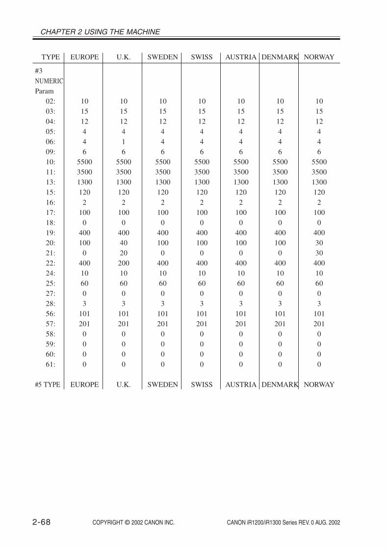
CHAPTER 2 USING THE MACHINE
COPYRIGHT © 2002 CANON INC. 2000 2000 2000 2000 CANON iR1200/iR1300 Series REV. 0 AUG. 20022-68
TYPE EUROPE U.K. SWEDEN SWISS AUSTRIA DENMARK NORWAY
#3NUMERICParam
02: 10 10 10 10 10 10 1003: 15 15 15 15 15 15 1504: 12 12 12 12 12 12 1205: 4 4 4 4 4 4 406: 4 1 4 4 4 4 409: 6 6 6 6 6 6 610: 5500 5500 5500 5500 5500 5500 550011: 3500 3500 3500 3500 3500 3500 350013: 1300 1300 1300 1300 1300 1300 130015: 120 120 120 120 120 120 12016: 2 2 2 2 2 2 217: 100 100 100 100 100 100 10018: 0 0 0 0 0 0 019: 400 400 400 400 400 400 40020: 100 40 100 100 100 100 3021: 0 20 0 0 0 0 3022: 400 200 400 400 400 400 40024: 10 10 10 10 10 10 1025: 60 60 60 60 60 60 6027: 0 0 0 0 0 0 028: 3 3 3 3 3 3 356: 101 101 101 101 101 101 10157: 201 201 201 201 201 201 20158: 0 0 0 0 0 0 059: 0 0 0 0 0 0 060: 0 0 0 0 0 0 061: 0 0 0 0 0 0 0
#5 TYPE EUROPE U.K. SWEDEN SWISS AUSTRIA DENMARK NORWAY

COPYRIGHT © 2002 CANON INC. 2000 2000 2000 2000 CANON iR1200/iR1300 Series REV. 0 AUG. 2002 2-69
CHAPTER 2 USING THE MACHINE
TYPE HOLLAND BELGUIM AUSTRALIA FINLAND N.Z. ITALY SPAIN
#3NUMERICParam
02: 10 10 10 10 10 10 1003: 15 15 15 15 15 15 1504: 12 12 12 12 12 12 1205: 4 4 4 4 4 4 1506: 4 4 4 4 4 4 309: 6 6 6 6 6 6 610: 5500 5500 5500 5500 5500 5500 550011: 3500 3500 3500 3500 3500 3500 350013: 1300 1300 1300 1300 1300 1300 130015: 120 120 120 120 120 120 12016: 2 2 2 2 2 2 217: 100 100 100 100 100 100 10018: 0 0 0 0 0 0 019: 400 400 400 400 400 400 40020: 100 100 100 100 100 100 10021: 0 0 0 0 0 0 022: 400 300 400 400 400 400 40024: 10 10 10 12 10 10 1025: 60 60 60 60 60 60 6027: 0 0 0 0 0 0 028: 3 3 3 3 3 3 356: 101 101 101 101 101 101 10157: 201 201 201 201 201 201 20158: 0 0 0 0 0 0 059: 0 0 0 0 0 0 060: 0 0 0 0 0 0 061: 0 0 0 0 0 0 0
#5 TYPE HOLLAND BELGUIM AUSTRALIA FINLAND N.Z. ITALY SPAIN
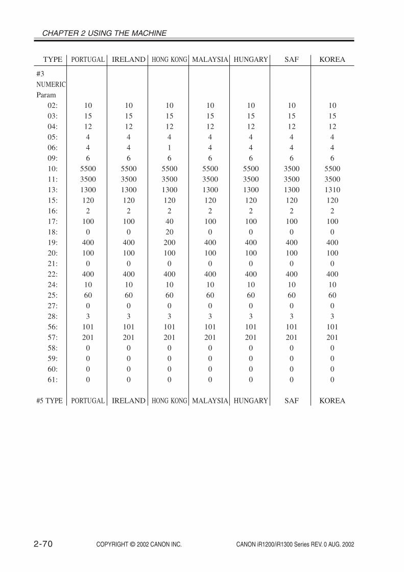
CHAPTER 2 USING THE MACHINE
COPYRIGHT © 2002 CANON INC. 2000 2000 2000 2000 CANON iR1200/iR1300 Series REV. 0 AUG. 20022-70
TYPE PORTUGAL IRELAND HONG KONG MALAYSIA HUNGARY SAF KOREA
#3NUMERICParam
02: 10 10 10 10 10 10 1003: 15 15 15 15 15 15 1504: 12 12 12 12 12 12 1205: 4 4 4 4 4 4 406: 4 4 1 4 4 4 409: 6 6 6 6 6 6 610: 5500 5500 5500 5500 5500 3500 550011: 3500 3500 3500 3500 3500 3500 350013: 1300 1300 1300 1300 1300 1300 131015: 120 120 120 120 120 120 12016: 2 2 2 2 2 2 217: 100 100 40 100 100 100 10018: 0 0 20 0 0 0 019: 400 400 200 400 400 400 40020: 100 100 100 100 100 100 10021: 0 0 0 0 0 0 022: 400 400 400 400 400 400 40024: 10 10 10 10 10 10 1025: 60 60 60 60 60 60 6027: 0 0 0 0 0 0 028: 3 3 3 3 3 3 356: 101 101 101 101 101 101 10157: 201 201 201 201 201 201 20158: 0 0 0 0 0 0 059: 0 0 0 0 0 0 060: 0 0 0 0 0 0 061: 0 0 0 0 0 0 0
#5 TYPE PORTUGAL IRELAND HONG KONG MALAYSIA HUNGARY SAF KOREA

COPYRIGHT © 2002 CANON INC. 2000 2000 2000 2000 CANON iR1200/iR1300 Series REV. 0 AUG. 2002 2-71
CHAPTER 2 USING THE MACHINE
TYPE CHINA GERMAN FRANCE SINGAPORE CZECH SLOVENIA ASIA
#3NUMERICParam
02: 10 8 10 10 10 10 1003: 15 15 15 15 15 15 1504: 12 6 12 12 12 12 1205: 4 4 4 4 4 4 406: 4 4 4 4 4 4 409: 6 6 6 6 6 6 610: 4500 9000 5500 5500 5500 5500 550011: 3500 3500 3500 3500 3500 3500 350013: 1300 1300 1300 1300 1300 1300 130015: 120 120 120 120 120 120 12016: 2 2 2 2 2 2 217: 100 100 100 100 100 100 10018: 0 0 0 0 0 0 019: 400 400 400 400 400 400 40020: 100 100 150 100 100 100 10021: 0 0 0 0 0 0 022: 400 400 300 400 400 400 40024: 10 10 10 10 10 10 1025: 60 60 60 60 60 60 6027: 0 0 0 0 0 0 028: 3 3 3 3 3 3 356: 101 101 101 101 101 101 10157: 201 201 201 201 201 201 20158: 0 0 0 0 0 0 059: 0 0 0 0 0 0 060: 0 0 0 0 0 0 061: 0 0 0 0 0 0 0
#5 TYPE CHINA GERMAN FRANCE SINGAPORE CZECH SLOVENIA ASIA
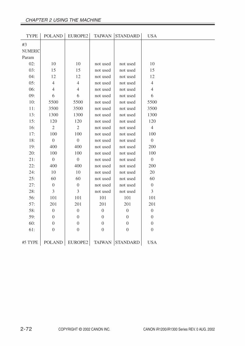
CHAPTER 2 USING THE MACHINE
COPYRIGHT © 2002 CANON INC. 2000 2000 2000 2000 CANON iR1200/iR1300 Series REV. 0 AUG. 20022-72
TYPE POLAND EUROPE2 TAIWAN STANDARD USA
#3NUMERICParam
02: 10 10 not used not used 1003: 15 15 not used not used 1504: 12 12 not used not used 1205: 4 4 not used not used 406: 4 4 not used not used 409: 6 6 not used not used 610: 5500 5500 not used not used 550011: 3500 3500 not used not used 350013: 1300 1300 not used not used 130015: 120 120 not used not used 12016: 2 2 not used not used 417: 100 100 not used not used 10018: 0 0 not used not used 019: 400 400 not used not used 20020: 100 100 not used not used 10021: 0 0 not used not used 022: 400 400 not used not used 20024: 10 10 not used not used 2025: 60 60 not used not used 6027: 0 0 not used not used 028: 3 3 not used not used 356: 101 101 101 101 10157: 201 201 201 201 20158: 0 0 0 0 059: 0 0 0 0 060: 0 0 0 0 061: 0 0 0 0 0
#5 TYPE POLAND EUROPE2 TAIWAN STANDARD USA

COPYRIGHT © 2002 CANON INC. 2000 2000 2000 2000 CANON iR1200/iR1300 Series REV. 0 AUG. 2002 2-73
CHAPTER 2 USING THE MACHINE
3.21 Test Mode (TEST MODE)3.21.1 Outline
When using test mode, be sure to execute items according to the menu indicated on thedisplay. The menu items in test mode are grouped into 7 blocks.
1.D-RAM Test (1: D-RAM)Use it to be sure that data is properly written to and read from the D-RAM.
2.CCD Test (2: CCD TEST)Use it to execute auto adjustment (contact sensor LED intensity or original read position)
or to initialize the CCD read position parameter.
3.PRINT Test (3: PRINT)Use it to generate a test pattern for service.
4.MODEM NCU Test (4: MODEM NCU)Use it to execute a relay operation test or modem DTMF and tonal signal transmission/
reception tests.
5.AGING Test (5: AGING TEST)Not used.
6.FACULTY Test (6: FACULTY TEST)Use it to check the operation of microswitches, sensors, speakers, and ADF.
7.BOOK Test (8: BOOK TEST)Use it to turn on the contact sensor or to initialize the book reading position parameter.

CHAPTER 2 USING THE MACHINE
COPYRIGHT © 2002 CANON INC. 2000 2000 2000 2000 CANON iR1200/iR1300 Series REV. 0 AUG. 20022-74
3.21.2 List of Test Mode ItemsTo use test mode, press the Additional Functions key and # key; then, select ‘SERVICE
MODE’ and select ‘TEST MODE’ using the Left or Right Arrow key, and press the OK key.To end test mode, press the Stop key and then the Additional Functions key.
1: D-RAM [1] - - - [3]
TEST MODE [1] - [6], [8]E120 : ###-##-##
******
2: CCD TEST [1] - - - [8]
3: PRINT [0] - - - [9] , [*] , [#]
3: PRINT (disabled) 3-1: WHITE
3: PRINT3-2: BLACK
3: PRINT (disabled)3-3: STRIPES
3: PRINT (disabled)3-4: CHECKERS
3: PRINT (disabled)3-5: CHECKERS-2
3: PRINT 3-6: ENDURANCE
3: PRINT (disabled)3-7: BLACK/WHITE
3: PRINT (disabled)3-0: AMI PATERN
3: PRINT (disabled)3-9: CHECKERS-3
1: D-RAM 14848K
1: D-RAM 14848K******
3: PRINT (disabled)3-8: BIAS
3: PRINT (disabled)3-*: PRINTING AREA
3: PRINT (disabled)3-#: CRG TEST
1-3: IRAM TEST (not used)
F02-321-01

COPYRIGHT © 2002 CANON INC. 2000 2000 2000 2000 CANON iR1200/iR1300 Series REV. 0 AUG. 2002 2-75
CHAPTER 2 USING THE MACHINE
4: MODEM NCU[1] - - - [8]
4-1. RELAY[1] - - - [2]
RELAY 1[0] - - - [5]
RELAY 1 1000001-0: CML ON
RELAY 1 0100001-1: P ON
RELAY 1 0010001-2: S ON
RELAY 1 0001001-3: H ON
RELAY 1 0000101-4: D ON
RELAY 1 0000011-5: R ON
RELAY 2 0000000000102-0: IPSEL2 ON
RELAY 2 1000000000002-1: NZ ON
RELAY 2 0100000000002-2: CI1 ON
RELAY 2 0010000000002-3: CI2 ON
RELAY 2 0001000000002-4: AST ON
RELAY 2 0000100000002-5: C1 ON
RELAY 2 0000010000002-6: C2 ON
RELAY 2 0000001000002-7: NOR ON
RELAY 2 0000000100002-8: DCSEL ON
RELAY 2 0000000010002-9: DCL1M ON
RELAY 2 0000000001002-*: IPSEL1 ON
RELAY 2 0000000000012-#: IPSEL3 ON
RELAY 2[0] - - - [9],[*],[#]
F02-321-02

CHAPTER 2 USING THE MACHINE
COPYRIGHT © 2002 CANON INC. 2000 2000 2000 2000 CANON iR1200/iR1300 Series REV. 0 AUG. 20022-76
4-2: FREQ[1] - - - [7]
4-2: FREQ 462 Hz
4-2: FREQ 1100 Hz
4-2: FREQ 1300 Hz
4-2: FREQ 1500 Hz
4-2: FREQ 1650 Hz
4-2: FREQ 1850 Hz
4-2: FREQ 2100 Hz
4-4: G3 Tx[0] - - - [8]
4-4: G3 Tx300 bps
4-4: G3 Tx2400 bps
4-4: G3 Tx4800 bps
4-4: G3 Tx7200 bps
4-4: G3 Tx9600 bps
4-4: G3 TxTC7200 bps
4-4: G3 TxTC9600 bps
F02-321-03

COPYRIGHT © 2002 CANON INC. 2000 2000 2000 2000 CANON iR1200/iR1300 Series REV. 0 AUG. 2002 2-77
CHAPTER 2 USING THE MACHINE
4-5: DTMF Tx TEST 4-5: DTMF Tx TEST0:
4-5: DTMF Tx TEST1:
4-5: DTMF Tx TEST2:
4-5: DTMF Tx TEST3:
4-5: DTMF Tx TEST4:
4-5: DTMF Tx TEST5:
4-5: DTMF Tx TEST6:
4-5: DTMF Tx TEST7:
4-5: DTMF Tx TEST8:
4-5: DTMF Tx TEST9:
4-5: DTMF Tx TEST
[0] - - - [9], [*] , [#]
4-5: DTMF Tx TEST#:
4-4: G3 Tx14400 bps
4-4: G3 Tx12000 bps
F02-321-04

CHAPTER 2 USING THE MACHINE
COPYRIGHT © 2002 CANON INC. 2000 2000 2000 2000 CANON iR1200/iR1300 Series REV. 0 AUG. 20022-78
4-6. TONE Rx 000
4-8: V.34 G3 Tx TEST[0] --- [5] UP-DOWN
5: AGING TEST (not used)
4-8: V.34 G3 Tx TESTBaud: 3429 Speed: 33.6
4-8: V.34 G3 Tx TESTBaud: 2400 Speed: 21.6
4-8: V.34 G3 Tx TESTBaud: 3000 Speed: 28.8
4-8: V.34 G3 Tx TESTBaud: 2800 Speed: 26.4
4-8: V.34 G3 Tx TESTBaud: 2743 Speed: 24.0
4-8: V.34 G3 Tx TESTBaud: 3200 Speed: 31.2
F02-321-05

COPYRIGHT © 2002 CANON INC. 2000 2000 2000 2000 CANON iR1200/iR1300 Series REV. 0 AUG. 2002 2-79
CHAPTER 2 USING THE MACHINE
6: FACULTY TEST[1] - - - [9], [#]
6-1: G3 4800 bps Tx4800 bps
6-2: REGISTRATIONREGISTRATION SW OFF
6-3: SENSOR[1]---[4]
DS of DES of DDS ofCRG on DCVS on
MLT on A4 TN onJAM of
HPS on BCVS ofTBS on WTS of
6-4: ADF
6-6: SPEAKERFREQ : [1] VOL : [2]
6-7: OPERATION PANEL
6-6: SPEAKERFREQ TEST
6-6:SPEAKERVOL [*]:MIN [#]:MAX
6-5: STAMP[1] - - - [2]
CT1 on A4
6-9: LINE DETECT[1] - - - [3]
6-#: ESS TEST
C1=OFF 0 HzHOOK=ON/ON FC=OFF (not used)
CNG DETECT (not used)CNG=OFF OFF
CNG DETECTCNG=OFF OFF
not used
F02-321-06

CHAPTER 2 USING THE MACHINE
COPYRIGHT © 2002 CANON INC. 2000 2000 2000 2000 CANON iR1200/iR1300 Series REV. 0 AUG. 20022-80
8: BOOK TEST[1] - - - [6]
8-1: BOOK FEED TESTP.0000/0000
8-2: BOOK ADJP.0000/0000
8-3: CS POS ADJ (ADF)
8-4:
8-5: BOOK TEST
8-6: BOOK TEST
F02-321-07

COPYRIGHT © 2002 CANON INC. 2000 2000 2000 2000 CANON iR1200/iR1300 Series REV. 0 AUG. 2002 2-81
CHAPTER 2 USING THE MACHINE
3.21.3 D-RAM Test (1: D-RAM)Press ‘1’ on the keypad on the Test Mode menu to select D-RAM (SDRAM) Test mode.
Thereafter, press ‘1’ or ‘2’ on the keypad to execute the following:
‘1’ on KeypadPress it to execute a data write/read check for the entire area of the D-RAM (SDRAM). If
an error occurs during the check, the machine will stop the check and indicate an error onthe LCD.
‘2’ on KeypadPress it to execute a data read check for the entire area of the D-RAM (SDRAM). If an
error occurs during the check, the machine will stop the check and indicate an error on theLCD.
1:D-RAM 14848K*******......
1:D-RAM 14848K......
Press '1' on the keypad.
Press the OK key.
14848K : indicates the total size of memory of the D-RAM (in bytes).* : indicates the memory size for data write operation.. : indicates the memory size for data read operation.
14848K : indicates the total memory of the D-RAM (in bytes).. : indicates the memory size for data write operation.
Indicated only when image data exists in the D-RAM.OK: press the OK key to clear the image data in the D-RAM.NO: press the Stop key to return to TEST MODE.
Press '2' on the keypad.
PIX RECORD CLEAR ?OK<OK>, NO<STOP>
1:D-RAM 14848K[1] - - - [3]
1:D-RAM 14848Kcomplete (no error)
Normal end
WRT= 33CC RD= 33ECADR= BF840201
1:D-RAM 14848Kcomplete (error)
Error end
Press the Start key to resume.
Error indication
WRT : data written.RD : data read.ADR : address.
F02-321-08

CHAPTER 2 USING THE MACHINE
COPYRIGHT © 2002 CANON INC. 2000 2000 2000 2000 CANON iR1200/iR1300 Series REV. 0 AUG. 20022-82
3.21.4 CCD Test (2: CCD TEST)A press on ‘2’ on the keypad on the Test Mode menu will select CCD Test mode. Press
‘3’, ‘7’, or ‘8’ on the keypad to execute the following:
‘3’ on KeypadPress it to execute original read position auto adjustment (if equipped with ADF) so as to
adjust the contact sensor position used for reading with the ADF in use automatically. (See1.3.4.2 of Chapter 7.)
‘7’ on KeypadPress it to initialize the contact sensor parameters, including those that are not initialized
by ‘all clear’ in service mode.
‘8’ on KeypadPress it to execute contact sensor LED intensity auto adjustment so that the contact sensor
output correction is made and contact sensor parameters are automatically set. (See 1.2.4.1of Chapter 7.)

COPYRIGHT © 2002 CANON INC. 2000 2000 2000 2000 CANON iR1200/iR1300 Series REV. 0 AUG. 2002 2-83
CHAPTER 2 USING THE MACHINE
3.21.5 PRINT Test (3: PRINT)Press ‘3’ on the keypad from the Test Mode men u to select Print Test mode. A press on ‘2’
or ‘6’ on the keypad during the test will generate any of the following 2 types of test pat-terns. Do not use the others, as they are especially designed for use by the factory and R&D.
‘2’ on Keypad3-2: Press it to generate BLACK, which is a solid black print.
‘6’ on Keypad3-6: Press it to generate ENDURANCE, which is a black band.
To stop test printing, press the Stop key.
Check to make sure that the printpattern is free of contraction, elongation, dirt, or black lines.
Check it to make sure that theprint pattern is free of white line or uneven density.
F02-321-09
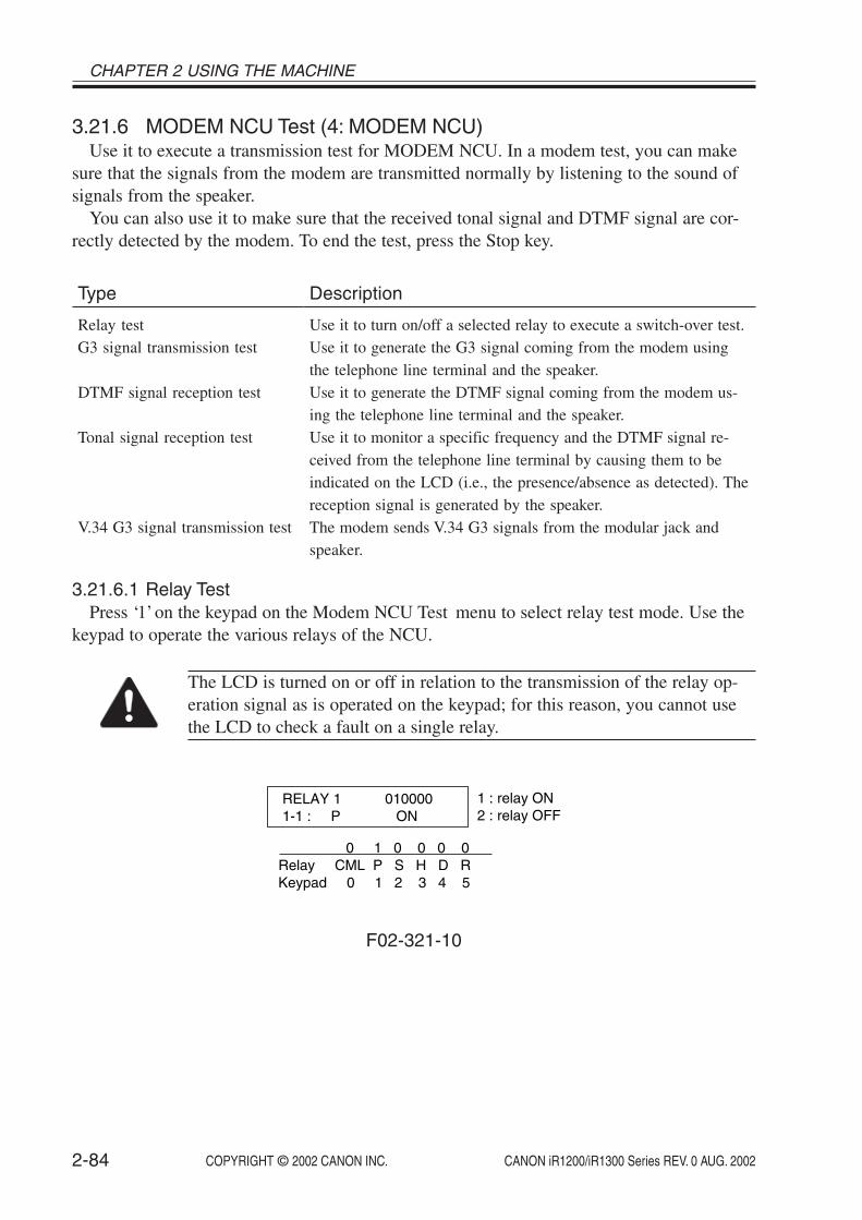
CHAPTER 2 USING THE MACHINE
COPYRIGHT © 2002 CANON INC. 2000 2000 2000 2000 CANON iR1200/iR1300 Series REV. 0 AUG. 20022-84
3.21.6 MODEM NCU Test (4: MODEM NCU)Use it to execute a transmission test for MODEM NCU. In a modem test, you can make
sure that the signals from the modem are transmitted normally by listening to the sound ofsignals from the speaker.
You can also use it to make sure that the received tonal signal and DTMF signal are cor-rectly detected by the modem. To end the test, press the Stop key.
Type
Relay testG3 signal transmission test
DTMF signal reception test
Tonal signal reception test
V.34 G3 signal transmission test
Description
Use it to turn on/off a selected relay to execute a switch-over test.Use it to generate the G3 signal coming from the modem usingthe telephone line terminal and the speaker.Use it to generate the DTMF signal coming from the modem us-ing the telephone line terminal and the speaker.Use it to monitor a specific frequency and the DTMF signal re-ceived from the telephone line terminal by causing them to beindicated on the LCD (i.e., the presence/absence as detected). Thereception signal is generated by the speaker.The modem sends V.34 G3 signals from the modular jack andspeaker.
3.21.6.1 Relay TestPress ‘1’ on the keypad on the Modem NCU Test menu to select relay test mode. Use the
keypad to operate the various relays of the NCU.
The LCD is turned on or off in relation to the transmission of the relay op-eration signal as is operated on the keypad; for this reason, you cannot usethe LCD to check a fault on a single relay.
RELAY 1 0100001-1 : P ON
1 : relay ON2 : relay OFF
0 1 0 0 0 0Relay CML P S H D RKeypad 0 1 2 3 4 5
F02-321-10

COPYRIGHT © 2002 CANON INC. 2000 2000 2000 2000 CANON iR1200/iR1300 Series REV. 0 AUG. 2002 2-85
CHAPTER 2 USING THE MACHINE
3.21.6.2 Frequency TestA press on ‘2’ on the keypad from the MODEM NCU Test menu selects the frequency
test. In this test, signals of the following frequencies from the modem are transmitted usingthe telephone line terminal and the speaker. To select a different frequency, use the keypad.
Keypad
1234567
Frequency
462 Hz1100 Hz1300 Hz1500 Hz1650 Hz1850 Hz2100 Hz
Keypad
012345678
Transmission speed
300 bps2400 bps4800 bps7200 bps9600 bpsTC7200 bpsTC9600 bps12000 bps14400 bps
Memo
The frequency and the output level of individual frequencies are in keepingwith the output level set in service mode.
3.21.6.3 G3 Signal Transmission TestA press on ‘4’ on the keypad from the MODEM NCU Test menu selects the G3 signal
transmission test. In this test, the following G3 signals from the modem are transmitted us-ing the telephone line terminal and the speaker. To select a different transmission speed, usethe keypad.
Memo
The output level of individual signals is in keeping with the setting made inservice mode.

CHAPTER 2 USING THE MACHINE
COPYRIGHT © 2002 CANON INC. 2000 2000 2000 2000 CANON iR1200/iR1300 Series REV. 0 AUG. 20022-86
3.21.6.4 DTMF Signal Transmission TestA press on ‘5’ on the MODEM NCU Test menu selects the DTMF signal transmission
test. In the test, the following DTMF signals from the modem are transmitted using the tele-phone line terminal and the speaker. The number pressed on the keypad selects a specificDTMF signal.
Memo
The output level of individual signals is in keeping with the setting made inservice mode.
3.21.6.5 Tonal/DTMF Signal Reception TestA press on ‘6’ on the keypad from the MODEM NCU Test menu selects the tonal signal/
DTMF signal reception 0 test. In this signal, the tonal signal/DTMF signal received from thetelephone line terminal can be checked to find out if it was detected by the modem.
4-6 : TONE Rx 000
0 0 0changes from '0' to '1' in response to detection of a signal of 1300 ± 25 Hz. changes from '0' to '1' in response to detection of a signal of 400 ± 30 Hz.changes from '0' to '1' in response to detection of a signal of 1100 ± 25 Hz.
Tonal signal reception test
4-6 : TONE Rx 000 1 2 3 4 5 6 7 8 9 0
DTMF signal reception test
The received DTMF signals are indicated starting from the right using the 2nd character of the display.
F02-321-11

COPYRIGHT © 2002 CANON INC. 2000 2000 2000 2000 CANON iR1200/iR1300 Series REV. 0 AUG. 2002 2-87
CHAPTER 2 USING THE MACHINE
3.21.6.6. V.34 G3 signal transmission testThe V.34 G3 signal transmission test menu is selected by pressing the 8 key from the MO-
DEM NCU test menu. The V.34 G3 signals below are sent from the modem using the modu-lar jack and the speaker by pressing the start key.
The Baud rate can be changed with the numeric keys, and the Speed can be changed withthe cursor key .
Numeric key
012345
Baud rate
3429 baud3200 baud3000 baud2800 baud2743 baud2400 baud
Cursor key Speed
2400 bps4800 bps7200 bps9600 bps12000 pbs14400 bps16800 bps19200 bps21600 bps24000 bps26400 bps28800 pbs31200 bps33600 bps

CHAPTER 2 USING THE MACHINE
COPYRIGHT © 2002 CANON INC. 2000 2000 2000 2000 CANON iR1200/iR1300 Series REV. 0 AUG. 20022-88
3.21.7 AGING Test (5: AGING TEST)Not used.
3.21.8 FACULTY (function) Test (6: FACULTY TEST)A press on ‘6’ on the keypad from the TEST MODE menu selects the FACULTY test. A
press on the keypad (1 through 7, 9, #) during the test will bring up the following menu:
Keypad
1
234567
9
#
Item
G3 Signal Transmission Test
not usedSensor TestADF Testnot usedSpeaker TestControl Panel Test
Live Connection Reception Test
ESS Test
Description
Transmits a G3 signal at 4800 bps to the telephoneline and the speaker.
Executes an operation test on a specific sensor.Executes an operation test on the ADF.
Executes an operation test on the speaker.Executes an operation test on the LCD/LED/controlpanel keys.Executes an operation test on the signal sensor onthe NCU board and the frequency counter.Executes an operation test on the ESS function.
G3 Signal Transmission Test (6-1: G3 4800 bps Tx)A press on ‘1’ on the keypad on the FACULTY TEST menu selects the G3 transmission
test. In this test, a G3 signal is transmitted using the telephone line terminal and the speakerat 4800 bps.
Sensor Test (6-3: SENSOR)This mode is used to check the state of a specific sensor of the machine on the LCD. A
press on ‘3’ on the keypad from the FACULTY TEST menu selects the sensor test. The LCDindication changes as the sensor goes ON and OFF.
The paper leading edge sensor (PS102), LGL paper sensor (PS101), anddelivery sensor (PS3) cannot be checked by running a sensor test.

COPYRIGHT © 2002 CANON INC. 2000 2000 2000 2000 CANON iR1200/iR1300 Series REV. 0 AUG. 2002 2-89
CHAPTER 2 USING THE MACHINE
6-3:SENOR[1] - - - [4]
DS of DES of DDS ofCRG on DCVS on
HPS on BCVS ofTBS on WTS of
CT1 on A4
MLT on A4 TN on JAM of
Press '1' on the keypad.
DS: original sensor*1 (PS6); 'on' if present, 'of' if absent.DES: registration sensor*1 (PS7); 'on' if present, 'of' if absent.DDS: original delivery sensor*1(PS8);'on' if present, 'of' if absent.CRG: not usedDCVS: Reader unit slide detecting switch (SW1) and toner supply cover open/closed detecting switch (SW2):
'on' reader unit in position and toner supply cover closed,'of' reader unit not in position or toner supply cover open.
*1: indicates the state of a specific sensor of the ADF.
Press '2' on the keypad.
HPS: contact sensor home position sensor (PS1): 'on' contact sensor in home position, 'of' contact sensor not in home position.
BCVS: ADF (copyboard cover) open/close sensor (PS2); 'on' cover open, 'of' cover closed.TBS: toner bottle sensor (PS11):
'on' toner bottle fitted,'of' toner bottle not fitted (cartridge not fitted).
WTS: waste toner full sensor (PS12):'on' if present, 'of' if absent.
Press '3' on the keypad.
CT1: cassette paper sensor (P103); 'on' paper present, 'of' paper absent.
Press '4' on the keypad.
MLT:manual feed tray paper sensor (PS4); 'on' paper present, 'of' paper absent.TN: not used.JAM: not used.
F02-321-12

CHAPTER 2 USING THE MACHINE
COPYRIGHT © 2002 CANON INC. 2000 2000 2000 2000 CANON iR1200/iR1300 Series REV. 0 AUG. 20022-90
ADF Test (6-4: ADF)Use it to check the operation of the ADF.Press ‘4’ on the keypad while the FACULTY TEST menu is indicated to select ADF test.
Place an original in the original placement area, and press the Start key so that the originalwill be moved at a specific speed.
Select this item, press 10 originals in the ADF, and press ‘8’ on the keypad to execute reg-istration arch auto adjustment (only if equipped with ADF functions). (See 1.3.4 of Chapter7.)
Speaker test (6-6: SPEAKER)Use it to check the operation of the speaker.Press ‘6’ on the keyboard while the FACULTY TEST menu is indicated to select speaker
test. In the test, tonal signal sounds of between 200 Hz to 5 kHz at 100-Hz intervals are gen-erated white changing the volume. Check to see if the speaker generates these signals.
6-6: SPEAKERFREQ:[1] VOL:[2]
Press '1' on the keypad.
6-6: SPEAKERFREQ TEST
6-6: SPEAKERVOL[*] :MIN [#]:MAX
Press '2' on keypad.
Press the Start key to change the transmission frequency.
Adjust the volume of the signals; at *, min.; at #, max.; may be changed in steps by pressing the Start key.
F02-321-13

COPYRIGHT © 2002 CANON INC. 2000 2000 2000 2000 CANON iR1200/iR1300 Series REV. 0 AUG. 2002 2-91
CHAPTER 2 USING THE MACHINE
Control Panel Test (6-7: OPERATION PANEL)This test is used to check the operation of the control panel.A press on ‘7’ on the keypad from the control panel selects the OPERATION PANEL Test
menu, enabling the following tests:
• LCD TestA press on the Start key under OPERATION PANEL test will start LCD test, in which
the screen will be filled with the character H; another press will cause the screen to turntotally black.
• LED Lamp TestA press on the Start key after the LCD test selects the LED lamp test, turning all lamps
in the control panel to go ON.• Control Key Test
A press on the Start key after the LED lamp selects control key test 1. Press the key in-dicated on the LCD; if it goes out, the operation is normal.
When all characters have gone out, control key test 2 (if equipped with fax functions) isstarted. As in the case of operation key test 1, press the key indicated on the LCD; the op-eration is correct if it goes out.
Key Correspondence for Control Key Test 1 (if not equipped with fax functions)
OK
[E] [A] [C]
[F] [B][G]
[H][J]
[I]
[D] Same as LCD indications.
F02-321-14

CHAPTER 2 USING THE MACHINE
COPYRIGHT © 2002 CANON INC. 2000 2000 2000 2000 CANON iR1200/iR1300 Series REV. 0 AUG. 20022-92
Key Correspondence for Control Key Test 1 (if equipped with fax functions)
Same as LCD indications.
[I ] [B] [D] [G] [F]
[J] [C][K]
[L][P]
[M]
[E]
[H][N][R]
[A] [Q] [O]
OK
Report
MemoryReference
Fax Monitor
DelayedTransmission
Book Sending
Clear
Delete
Space
Tone/+
Function
Redial / Pause
Coded Dial
Directory
Receive Mode
Fax Resolution
D.T.
R
ABC DEF
GHI JKL MNO
PQRS TUV WXYZ
F02-321-15
Key Correspondence for Control Key Test 2 (if equipped with fax functions)
[9] [8] [7]
[1]
[2]
[3]
[4]
[5]
[6]
[a] [b] [c]
Report
MemoryReference
Fax Monitor
DelayedTransmission
Book Sending
Clear
Delete
Space
Tone/+
Function
Redial / Pause
Coded Dial
Directory
Receive Mode
Fax Resolution
D.T.
R
F02-321-16

COPYRIGHT © 2002 CANON INC. 2000 2000 2000 2000 CANON iR1200/iR1300 Series REV. 0 AUG. 2002 2-93
CHAPTER 2 USING THE MACHINE
The following is the flow of work for the control panel test:
Press the Start key.
Character H is indicated.
The screen turns totally black.
All LED lamps go ON.
A press on the key causes its corresponding character to go out.
A press on a 1-touch dial key causes its corresponding character to go out.
LCD test
LED lamp test
Control key test (1)
Press the Start key.
6 - 7 : OPERAT I ON PANE L
Press the Start key.
Press the Start key.
Control key test (2)After all characters are gone, press the Stop key to end the test.
HHHHHHHHHHHHHHHHHHHHHHHHHHHHHHHHHHHHHHHH
L ED TES T6 - 7 : OPERAT I ON PANE L
0 1 2 3 4 5 6 7 8 9 * # ABCDEFGH I J K LMNOPQR
1 2 3 4 5 6 7 8 9 a b c
F02-321-17

CHAPTER 2 USING THE MACHINE
COPYRIGHT © 2002 CANON INC. 2000 2000 2000 2000 CANON iR1200/iR1300 Series REV. 0 AUG. 20022-94
Line Connection Reception Test (6-9: LINE DETECT)A press on ‘9’ on the keypad from the FACULTY TEST menu selects the LINE DETECT
test. On Test Menu 1, you can check C1, FC, state of hooking of the eternal telephone, andthe detection of signals by the NCU package.
Test Menu 1A press on ‘1’ on the keypad from the LINE DETECT menu selects test menu 1. In this
test, the LCD indication changes from ‘OFF’ to ‘ON’ when C1, FC, or off-set of the externaltelephone is detected in relation to the telephone line.
Test Menu 3A press on ‘3’ on the keypad from the LINE DETECT menu selects test menu 3. In this
test, the LCD indication changes from ‘OFF’ to ‘ON’ when CNG is detected in relation tothe telephone terminal.
ESS Test (6-#: ESS TEST)A press on the # key from the FACULTY TEST menu executes the ESS (Energy Save
Stanby: hereafter, ESS) test. In the course of execution, the test causes the machine to be inESS mode, causing all LEDs except the Energy Saver key in the control panel to go OFF.The machine ends ESS mode for the following:• The Energy Saver key is pressed.• Print data arrives from the PC.• A fax arrives. *1
• Off-hook set is detected. *1
• The report output time arrives. *1
• The timer call time arrives. *1
*1: If equipped with fax functions.
3.21.9 BOOK Read Test (8: BOOK TEST)A press on ‘8’ on the keypad from the TEST MODE menu selects the BOOK test. A press
on ‘4’ or ‘6’ on the keypad during this test initializes the corresponding parameter as de-scribed below:
‘4’ on the KeypadThe book read position parameter (#6 SCANNER 7: CCD 21, 23) is initialized.
‘6’ on the KeypadThe BOOK read parameter (#6 SCANNER 7: CCD 18*1, 19, 21, 23) is initialized.
*1: The term “CCD18 setting” refers to the setting for original read position adjustment ex-ecuted by a press on ‘3’ of the keypad under ‘CCD TEST’ of ‘TEST MODE’.

COPYRIGHT © 2002 CANON INC. 2000 2000 2000 2000 CANON iR1200/iR1300 Series REV. 0 AUG. 2002 2-95
CHAPTER 2 USING THE MACHINE
3.22 Service Report3.22.1 Manually Generating Reports
The following reports may be generated manually in service mode:
Operation
Select an item under [#10 REPORT] from theservice mode menu, and press the OK key. Or,press Function key and Report key in this orderin service mode. Then select the list to output,and press OK key.
Type of report
SYSTEM (SERVICE) DATA LISTSYSTEM DUMP LISTKEY HISTORY REPORTCOUNTER REPORTPRINT SPEC REPORT
T02-322-01
3.22.1.1 SYSTEM (SERVICE) DATA LISTThe following shows the service soft switch settings and the service parameter settings:
---------- ------------------------------ ---------------
SW01
SSSW#1
SW02SW03SW04SW05SW06SW07SW08SW09SW10SW11SW12SW13SW14SW15SW16SW17SW18SW19SW20SW21SW22SW23
000100000000000000000000100000000000000010010000000000000000000000000000000000000000000000000010000000000000000100000000000000110000001000000000000000000000000000000000000000000000000000000000000000000000000000000000
02/01/2001 13:49 FAX 001
---------- ------------------------------ ------------------------- -----
* * * * * * * * * * * * * * * * * * * * ** * * * * ** * * * * * * * * * * * * * * * * * * * *
SYSTEM DATA LIST
F02-322-01

CHAPTER 2 USING THE MACHINE
COPYRIGHT © 2002 CANON INC. 2000 2000 2000 2000 CANON iR1200/iR1300 Series REV. 0 AUG. 20022-96
3.22.1.2 SYSTEM DUMP LISTThe following shows a record of communications and error communications:
CLEAR DATE 02/01/2001
TXA4RXA414400144009600STDMHG3PRINT
#000 0 0 0 0 0 0 0 0 0 0 0 0 0
0 0 0 0 0 0 0 0 0 0 0 0 0
0 0 0 0 0 0 0 0 0 0 0 0 0
0 0 0 0 0 0 0 0 0 0 0 0 0
0 0 0 0 0 0 0 0 0 0 0 0 0
0 0 0 0 0 0 0 0 0 0 0 0 0
0 0 0 0 0 0 0 0 0 0 0 0 0
0 0 0 0 0 0 0 0 0 0 0 0 0
#700 0 0 0 0 0 0 0
0 0 0 0 0 0 0
0 0 0 0 0 0 0
0 0 0 0 0 0
0 0 0 0 0
0 0 0 0
0 0 0
0 0 0
===========
00000000009 / 209 READ = 1 / 140
02/01 2001 13:54 FAX 001
B4
B412000120007200FINEMRECM
=
=======
0
0000000
A3
A3TC9600
4800SUPER
=
==
==
0
00
00
MMR = 0
LTRTC7200
2400ULTRA
==
==
00
00
JBIG = 0
LGL =
0
12345
6789
10
*****
****
*
F02-322-02
*1: TX; total number of transmitted pages.*2: Number of transmitted pages by original size.*3: RX; total number of received pages.*4: Number of received pages by original size.*5: Number of transmitted/received pages by modem speed.*6: Number of transmitted/received pages by mode (Standard, Fine, Super Fine, Ultra Fine).*7: Number of transmitted/received pages by coding method.*8: Number of transmissions/receptions by mode.*9: Number of prints, total number of prints; number of pages read, total number of pages
read.*10: Number of occurrences of specific error codes.
Guide to Indication
##000 1Number of##000 errors
7Number of##001 errors
3Number of##002 errors
0 0

COPYRIGHT © 2002 CANON INC. 2000 2000 2000 2000 CANON iR1200/iR1300 Series REV. 0 AUG. 2002 2-97
CHAPTER 2 USING THE MACHINE
The report indicates the most recent 3 communication errors:
START TIME 02/08 19:30OTHER PARTYMAKER CODE 10001000MACHINE CODE 10011100 00000000
Rx : (bit 1) 00000000 01110010 00011111 00100010 00000000 00000000 00000000 (bit56)Tx : (bit 1) 00000000 01110111 00010001 00100011 00000001 10101011 11000001 (bit56)
(bit57) 00000001 00000001 00000100 00000000 00000000 (bit96)
Rx : NSS TSI DCS PIX
Tx : NSF DIS CFR
23
1
4567
8
#1 LATEST ##0793
#2 ##0765
*
1*
*
******
F02-322-03
*1: Service error code.*2: START TIME: date and time (in 24-hr notation).*3: OTHER PARTY; telephone number sent by other party.*4: MAKER CODE; manufacturer code.*5: MACHINE CODE: code by model.*6: Bit 1 through 48 of DIS, DCS, or DTC received.*7: Bit 1 through 48 of DIS, DCS, or DTC transmitted.*8: RX: received procedure signal.
TX: transmitted procedure signal.

CHAPTER 2 USING THE MACHINE
COPYRIGHT © 2002 CANON INC. 2000 2000 2000 2000 CANON iR1200/iR1300 Series REV. 0 AUG. 20022-98
3.22.1.3 KEY HISTORY REPORTThe report indicates the most recent 1800 key presses:
02/01/2001 13:55 FAX
02/01 13:55:4802/01 13:55:4602/01 13:55:4502/01 13:55:4302/01 13:55:4102/01 13:55:4002/01 13:55:3902/01 13:55:3702/01 13:54:0502/01 13:54:0402/01 13:54:0302/01 13:54:0202/01 13:52:5402/01 13:51:4002/01 13:51:2502/01 13:51:2002/01 13:51:1902/01 13:50:1702/01 13:50:5302/01 13:50:51
02/01 13:51:40
02/01 13:50:5302/01 13:50:5202/01 13:50:51
SET_KEYPREV_KEYPREV_KEYNEXT_KEYNEXT_KEYPREV_KEYPREV_KEYUSER_KEYNEXT_KEYSET_KEYPREV_KEYSHARP_KEYSTOP_KEYSTOP_KEYNEXT_KEYPREV_KEYPREV_KEYUSER_KEYSTOP_KEYSTOP_KEY
02/01 13:55:4702/01 13:55:4502/01 13:55:4402/01 13:55:4202/01 13:55:4002/01 13:55:39 02/01 13:55:3902/01 13:54:0602/01 13:54:0502/01 13:54:0402/01 13:54:0302/01 13:52:5402/01 13:52:4002/01 13:51:2202/01 13:51:2002/01 13:51:1902/01 13:51:1602/01 13:50:5202/01 13:50:5202/01 13:50:51
NEXT_KEYPREV_KEYNEXT_KEYNEXT_KEYNEXT_KEYPREV_KEYPREV_KEYSET_KEYNEXT_KEYPREV_KEYPREV_KEYSTOP_KEYSTOP_KEYNEXT_KEYPREV_KEYPREV_KEYUSER_KEYSTOP_KEYSTOP_KEYSTOP_KEY
02/01 13:55:4702/01 13:55:4502/01 13:55:4402/01 13:55:4102/01 13:55:4002/01 13:55:3902/01 13:55:3802/01 13:54:0602/01 13:54:0502/01 13:54:0402/01 13:54:0302/01 13:52:5402/01 13:51:2602/01 13:51:2102/01 13:51:1902/01 13:51:1802/01 13:51:1602/01 13:50:5202/01 13:50:5102/01 13:50:49
PREV_KEYPREV_KEYNEXT_KEYNEXT_KEYSET_KEYPREV_KEYSHARP_KEYPREV_KEYNEXT_KEYPREV_KEYPREV_KEYSTOP_KEYSTOP_KEYSET_KEYSET_KEYPREV_KEYSHARP_KEYUSER_KEYSTOP_KEYSTOP_KEY
001
* * * * * * * * * * * * * * * * * * * * ** * * * * ** * * * * * * * * * * * * * * * * * * * *
KEY HISTORY REPORT
F02-322-04

COPYRIGHT © 2002 CANON INC. 2000 2000 2000 2000 CANON iR1200/iR1300 Series REV. 0 AUG. 2002 2-99
CHAPTER 2 USING THE MACHINE
3.22.1.4 COUNTER REPORTThe various counter readings are indicated (3.14.1 of Chapter 2):
02/01/2001 13:58 FAX
T0TALSERVICE1 = 15SERVICE2 = 15TTL = 15COPY = 1PDL-PRT = 0FAX-PRT = 0RPT-PRT = 10SCAN = 1
JAMTTL = 0
MISCWST-TNR =
FEEDER = 0SORTER = 0MF = 0C1 = 0C2 = 0C3 = 0C4 = 0
PICK-UPC1 = 15
15
FEEDERFEED = 0
C2 = 0C3 = 0C4 = 0MF = 0
001
***************************** *****************************
COUNTER REPORT
F02-322-05

CHAPTER 2 USING THE MACHINE
COPYRIGHT © 2002 CANON INC. 2000 2000 2000 2000 CANON iR1200/iR1300 Series REV. 0 AUG. 20022-100
3.22.1.5 PRINT SPEC REPORTThe report indicates the TYPE settings, printing speed, memory size, ROM version, and
adjustment data.
02/01/2001 14:00 FAX 001
TYPE ----- EUROLBP SPEED ----- 13SHEETS
TOTAL MEMORY ----- 6656KMAIN ----- EURO-22-03MAIN2 ----- WLD-03-01ECONT ----- 0038CAPT ----- 0005
18 :READ ADJ PRM
----- 355121 : ----- 002523 : ----- 001024 : ----- 004525 : ----- 025834 : ----- 005035 : ----- 0130
F02-322-06
3.22.2 Automatically Generated ReportsThe following reports are generated automatically:
Type of report
Error TX report(w/ error code list, dump list)
RX report(w/ error code list, dump list)
Operation
Enable automatic generation on the report set-tings menu in user mode menu (i.e., use bits 0and 1 of SW01 of service data #1 SSSW).
Enable automatic generation on the report set-tings menu in user mode menu (i.e., use bits 0and 1 of SW01 of service data #1 SSSW).
T03-322-02

COPYRIGHT © 2002 CANON INC. 2000 2000 2000 2000 CANON iR1200/iR1300 Series REV. 0 AUG. 2002 2-101
CHAPTER 2 USING THE MACHINE
3.22.2.1 Error TX Report (for service)A service error code list and an error dump list may be attached to the error TX report. To
do so, use service SSSW-SW01 in service mode.If ‘attach’ is selected for ‘transmission image’ under ‘transmission result report’ of [RE-
PORT SETTING] in user mode, a part of the 1st page of the transmission image will be at-tached when memory transmission is used.
02/08/2001 19:29 FAX 001
START TIME 02/08 19:28OTHER PARTYMAKER CODE 10001000MACHINE CODE 10011100 00000000
Rx : (bit 1) 00000000 01110011 10011101 00100010 00000000 00000000 00000000 (bit56)Tx : (bit 1) 00000000 01100000 00011111 00100010 00000000 00000000 00000000 (bit56)
Rx : NSS CSI DIS CFR PPR
Tx : NSS DCS PIX PPS-EOP PIX PPS-EOP PPS-EOP PPS-EOP DCN
*1
*2*3*4*5*6*7
*8
TX FUNCTION WAS NOT COMPLETED
TX/RX NODESTINATION TEL #DESTINATION IDST. TIME
RESULT
TIME USEPGS.
000412
02/08 19:2801`31
0NG ##0765
12
ERROR TX REPORT***************************** *****************************
F02-322-07
*1: Service error code.*2: START TIME; date and time (in 24-hr notation).*3: OTHER PARTY; telephone number sent from other party.*4: MAKER CODE; manufacture code.*5: MACHINE CODE; model code.*6: Bits 1 through 48 of received DIS, DCS, or DTC.*7: Bits 1 through 48 of received DIS, DCS, or DTC.*8: RX: received procedure signal.
TX: transmitted procedure signal.

CHAPTER 2 USING THE MACHINE
COPYRIGHT © 2002 CANON INC. 2000 2000 2000 2000 CANON iR1200/iR1300 Series REV. 0 AUG. 20022-102
3.22.2.2 RX Report (for service)A service error code list and an error dump list may be attached to the RX report in re-
sponse to an error reception. To attach, use SSSW-SW01 in service mode.
02/08/2001 19:33 FAX 001
START TIME 02/08 19:30OTHER PARTYMAKER CODE 10001000MACHINE CODE 10011100 00000000
Rx : (bit 1) 00000000 01100110 00011111 00100010 00000000 00000000 00000000 (bit56)Tx : (bit 1) 00000000 01110111 00010001 00100011 00000001 10101011 11000001(bit56) (bit57) 00000001 00000001 00000100 00000000 00000000 (bit96)
Rx : NSS TSI DCS PIX
Tx : NSF DIS CFR
*1
*2*3*4*5*6*7
*8
INCOMPLETE RECEPTION
TX/RX NODESTINATION TEL #DESTINATION IDST. TIME
RESULT
TIME USEPGS.
5001
02/08 19:3003`02
1NG ##0793
***************************** *****************************
RX REPORT
F02-322-08
*1: Service error code.*2: START TIME; date and time (in 24-hr notation).*3: OTHER PARTY; telephone number sent from other party.*4: MAKER CODE; manufacture code.*5: MACHINE CODE; model code.*6: Bits 1 through 48 of received DIS, DCS, or DTC.*7: Bits 1 through 48 of received DIS, DCS, or DTC.*8: RX: received procedure signal.
TX: transmitted procedure signal.

COPYRIGHT © 2002 CANON INC. 2000 2000 2000 2000 CANON iR1200/iR1300 Series REV. 0 AUG. 2002
CHAPTER 3
INSTALLATION


COPYRIGHT © 2002 CANON INC. 2000 2000 2000 2000 CANON iR1200/iR1300 Series REV. 0 AUG. 2002 3-1
CHAPTER 3 INSTALLATION
1 Selecting the Site
The site must meet the following requirements; if possible, visit the user’s before the ma-chine is delivered:
1. The site must offer a power outlet whose rating is as specified volts (±10%) and whichmay be used exclusively for the machine.
2. The site temperature must be between 0° and 35°C (32° and 95°F) and between 35%and 85% humidity. Avoid an area near a water faucet, water boiler, humidifier, and re-frigerator.
3. The site must not be near a source of fire, or must not be subject to dust or ammoniumgas. Also, avoid areas exposed to direct rays of the sun; if necessary, provide curtains.
4. The level of ozone generated by the machine while in use will not affect the health ofthe human body. However, some individuals may find its odor unpleasant. Be sure toventilate the room well to provide a good working environment.
5. The machine will have to be at least 10cm/3.9" from any wall, offering enough space forits use.
50cm / 19.7"
50cm
/ 19
.7"
50cm / 19.7"
10cm / 3.9"
F03-101-01
6. The machine will have to be placed in a well-ventilated area of the room. Do not, how-ever, place it near the inlet of air.

CHAPTER 3 INSTALLATION
COPYRIGHT © 2002 CANON INC. 2000 2000 2000 2000 CANON iR1200/iR1300 Series REV. 0 AUG. 20023-2
2 Unpacking and Installing the Machine
2.1 Before Starting
Go through the following before starting to install the machine:
If the machine is moved from a cold to a warm place for installation, con-densation can develop in its pickup/feeding assembly, causing image faults.To avoid the condensation, leave the machine unpacked for 1 hr or more sothat it will be fully used to the room temperature.(The term condensation refers to the development of drops of water on amental surface when it is brought from a cold to warm place. This occurs asa result of rapid cooling of vapor in the air.)
2.2 Installation Procedure
Install the machine in the following order; for details, see the appropriate sections that fol-low; after installation, be sure to clean up the area around the machine:
1. unpacking2. fitting the cartridge3. setting the toner bottle4. putting paper in the cassette5. putting paper in the manual feed tray6. connecting the interface cable7. connecting the modular cable (if equipped with fax functions)8. connecting the power cord9. fitting the delivery tray10. checking the copy images11. setting the printer functions12. setting the fax functions (if equipped with fax functions)

COPYRIGHT © 2002 CANON INC. 2000 2000 2000 2000 CANON iR1200/iR1300 Series REV. 0 AUG. 2002 3-3
CHAPTER 3 INSTALLATION
2.3 Unpacking
Actions
1) Unpack the machine, and take out theattachments.
The toner bottle is not partof the shipment, but mustbe purchased separately.
2) Holding the grips on the left and right ofthe machine, lift it out of the box.
3) Remove the packing material: plasticsheets, securing members, and tape.
4) Remove the shipping screw.
Checks/remarks
Check to see that none of the following is missing:• cassette• delivery tray• cartridge (durm unit and developing unit)• power cord• Quick Start Guide• Reference Guide• CD-ROM• Warranty card
(Specific country/region models only.)• Modular cable (Specific country/region models
only.)• Fax Guide (if equipped with fax functions)• Others

CHAPTER 3 INSTALLATION
COPYRIGHT © 2002 CANON INC. 2000 2000 2000 2000 CANON iR1200/iR1300 Series REV. 0 AUG. 20023-4
Actions
5) While pulling on the reader unit slidelever, slide out the reader unit to theleft.
6) Open the cartridge cover.
7) Store away the securing member re-moved in step 4 in the shipping screwslot.
Checks/remarks

COPYRIGHT © 2002 CANON INC. 2000 2000 2000 2000 CANON iR1200/iR1300 Series REV. 0 AUG. 2002 3-5
CHAPTER 3 INSTALLATION
2.4 Fitting the Cartridge
Actions
1) Unpack the cartridge, and take it outwithout removing its wrappings.
2) Fully insert the cartridge in the direc-tion of the arrow as indicated.
3) Close the cartridge cover, and put backthe reader unit.
Checks/remarks

CHAPTER 3 INSTALLATION
COPYRIGHT © 2002 CANON INC. 2000 2000 2000 2000 CANON iR1200/iR1300 Series REV. 0 AUG. 20023-6
2.5 Fitting the Toner bottle
Actions
1) Open the toner supply cover.
2) Rock the new toner bottle five or sixtimes to distribute the toner evenly.
3) Holding the toner bottle lever, insert thetoner bottle slowly into the machine asfar as it will go.
Checks/remarks

COPYRIGHT © 2002 CANON INC. 2000 2000 2000 2000 CANON iR1200/iR1300 Series REV. 0 AUG. 2002 3-7
CHAPTER 3 INSTALLATION
Actions
4) Holding the toner bottle steady withone hand, firmly and slowly pull thesealing tape tab with the other hand toremove the sealing tape completely.Throw the tape away.
To avoid breaking the tape,do not pull it at an angle.
5) Holding the toner bottle lever, turn itcounterclockwise so that mark on thetoner bottle aligns with the mark onthe machine [1]. Close the toner car-tridge lever [2].
If you can’t turn the tonerbottle, please push it intoslot unit stop and turnagain.
6) Close the toner supply cover.
Checks/remarks
[1]
Before Complete
[2]
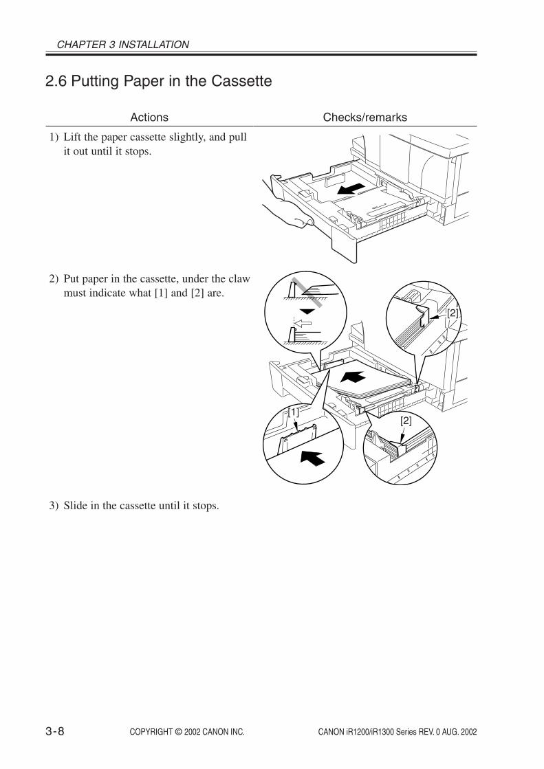
CHAPTER 3 INSTALLATION
COPYRIGHT © 2002 CANON INC. 2000 2000 2000 2000 CANON iR1200/iR1300 Series REV. 0 AUG. 20023-8
2.6 Putting Paper in the Cassette
Actions
1) Lift the paper cassette slightly, and pullit out until it stops.
2) Put paper in the cassette, under the clawmust indicate what [1] and [2] are.
3) Slide in the cassette until it stops.
Checks/remarks
[2]
[2]
[1]
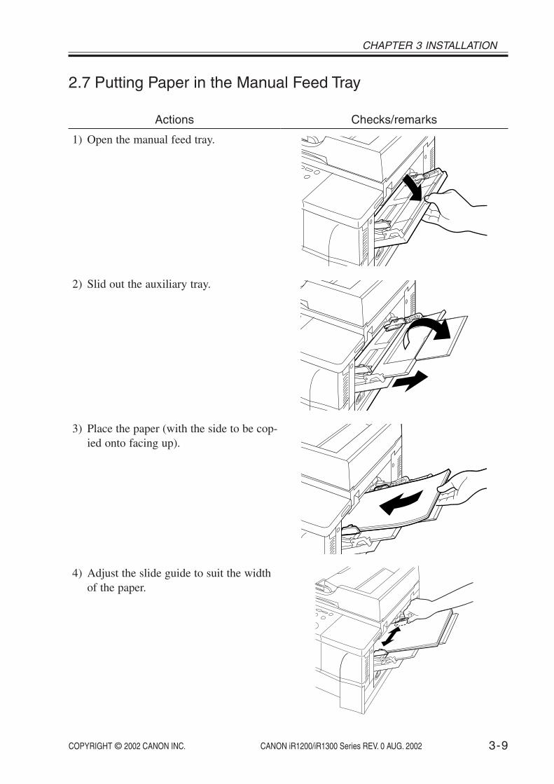
COPYRIGHT © 2002 CANON INC. 2000 2000 2000 2000 CANON iR1200/iR1300 Series REV. 0 AUG. 2002 3-9
CHAPTER 3 INSTALLATION
2.7 Putting Paper in the Manual Feed Tray
Actions
1) Open the manual feed tray.
2) Slid out the auxiliary tray.
3) Place the paper (with the side to be cop-ied onto facing up).
4) Adjust the slide guide to suit the widthof the paper.
Checks/remarks

CHAPTER 3 INSTALLATION
COPYRIGHT © 2002 CANON INC. 2000 2000 2000 2000 CANON iR1200/iR1300 Series REV. 0 AUG. 20023-10
2.8 Connecting the Interface Cable
Actions
1) Connect the cable to the USB port if aUSB cable is to be used, or to the paral-lel port if a parallel interface cable is tobe used. Be sure also to connect thecable to the PC.
Use interface cables thatcomply with specificationsof the machine.USB cable specifications:5 m or shorter.Parallel interface cablespecifications: 3 m orshorter (Compliant toIEEE1284, for bi-direc-tional communication)
Checks/Remarks
2.9 Connecting the Modular Cable (if equipped with fax func-tions)
Actions
1) Connect one end of the modular cableto the terminal [L], and the other end tothe socket of the telephone.If both telephone and fax are to beused, connect the modular cable fromthe telephone (or answering machine)to the [telephone] terminal.
Checks/Remarks
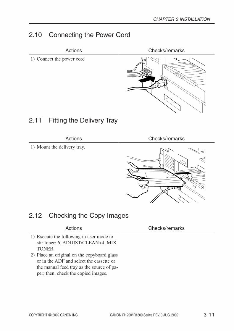
COPYRIGHT © 2002 CANON INC. 2000 2000 2000 2000 CANON iR1200/iR1300 Series REV. 0 AUG. 2002 3-11
CHAPTER 3 INSTALLATION
2.10 Connecting the Power Cord
2.11 Fitting the Delivery Tray
Actions
1) Connect the power cord
Checks/remarks
Actions
1) Mount the delivery tray.
Checks/remarks
2.12 Checking the Copy Images
Actions
1) Execute the following in user mode tostir toner: 6. ADJUST/CLEAN>4. MIXTONER.
2) Place an original on the copyboard glassor in the ADF and select the cassette orthe manual feed tray as the source of pa-per; then, check the copied images.
Checks/remarks

CHAPTER 3 INSTALLATION
COPYRIGHT © 2002 CANON INC. 2000 2000 2000 2000 CANON iR1200/iR1300 Series REV. 0 AUG. 20023-12
2.13 Setting the Printer Functions
Actions
1) Install printer drivers, and perform testprinting from the PC to check the im-ages.
Be sure that the PC envi-ronment meets the require-ments of the machine be-fore installing the printerdrivers.For details, refer to QuickStart Guide.
Checks/Remarks
COPYRIGHT © 2002 CANON INC. 2000 2000 2000 2000 CANON iR1200/iR1300 Series REV. 0 AUG. 2002 3-13
CHAPTER 3 INSTALLATION
2.14 Setting Fax Functions (if equipped with fax functions)2.14.1 Setting the Date/Time (user mode)
Actions
1) Press the Additional Functions key.2) Press the Left/Right Arrow key, to select
‘5. TIMER SETTING’.3) Press the OK key.4) Check to make sure that ‘1. DATE/
TIME SETTING’ is indicated and pressthe OK key.
5) Enter the current date and time. Pressthe Left/Right Arrow key to move thecursor to the character to enter and entera number using the keypad.
6) Press the OK key so that the date/timewill be stored.
Checks/remarks

CHAPTER 3 INSTALLATION
COPYRIGHT © 2002 CANON INC. 2000 2000 2000 2000 CANON iR1200/iR1300 Series REV. 0 AUG. 20023-14
2.14.2 Setting the Dial Type
Actions
1) Press the Additional Functions key.2) Press the Left/Right Arrow key to select
‘3. FAX SETTING’.3) Press the OK key.4) Check to see that ‘1. USER SETTING’
is indicated and press the OK key.5) Check to see that ‘1. TEL LINE SET-
TING’ is indicated and press the OKkey.
6) Press the Left/Right key to select ‘2.TEL LINE TYPE’.
7) Press the OK key.8) Press the Left/Right key to select
‘TOUCH TONE’ or ‘ROTARY PULSE’.9) Press the OK key so that the selected
line type is stored.
Checks/remarks
2.14.3 Executing Communications Testing
Actions
1) Press the Fax key in the control panelso that the machine will be in faxmode.
2) Try sending and receiving an originaland check the operation and the images.
Checks/remarks

COPYRIGHT © 2002 CANON INC. 2000 2000 2000 2000 CANON iR1200/iR1300 Series REV. 0 AUG. 2002 3-15
CHAPTER 3 INSTALLATION
3 When Relocating the MachineIf the machine must be moved by truck or other means of transportation, be sure to go
through the following:
1. If the machine is equipped with fax function and the move will take 2 hours or more, thefax image data, if any, will be lost. Advise the user on this and, if necessary, print out theimage data.
2. Be sure no communication is under way with an external device.3. Check that the contact sensor is in home position and disconnect the power cord.4. Disconnect the interface cable and modular cable.5. Remove the delivery tray.6. Slide the reader unit to the left, and open the cartridge cover.7. Take out the shipping screw that have been stored away inside the machine.
8. Take out the cartridge from inside of the machine and put it in a protective bag or thelike to avoid direct rays of the sun.
9. Close the cartridge cover and put back the reader unit.10. Fit the shipping screw you removed in step 7 and secure the contact sensor in place.
F03-301-02
F03-301-01

CHAPTER 3 INSTALLATION
COPYRIGHT © 2002 CANON INC. 2000 2000 2000 2000 CANON iR1200/iR1300 Series REV. 0 AUG. 20023-16
11. Open the ADF (copyboard cover) and place A4 (LTR) sheet on the copyboard glassthen, close the ADF (copyboard cover).
12. Tape the machine’s covers in place so that it will not open in transit.13. Pack the machine and start the relocation.
Take full care to avoid severe vibration during the relocation.

COPYRIGHT © 2002 CANON INC. 2000 2000 2000 2000 CANON iR1200/iR1300 Series REV. 0 AUG. 2002
CHAPTER 4
OPERATION


COPYRIGHT © 2002 CANON INC. 2000 2000 2000 2000 CANON iR1200/iR1300 Series REV. 0 AUG. 2002 4-1
CHAPTER 4 OPERATION
1 Basic Operation
1.1 Reproduction Processes1.1.1 Outline
The machine uses an indirect electrostatic method, and is constructed as shown in F04-101-01:
Copyboard glass
Contact sensor
Image processing block
Laser scanner assembly
Primary charging rollerCleaning blade
Cartridge
Developing cylinder
Vertical path rollerTransfer charging roller
Static eliminator
Fixing assembly
Paper
Paper
Photosensitive drum
F04-101-01

COPYRIGHT © 2002 CANON INC. 2000 2000 2000 2000 CANON iR1200/iR1300 Series REV. 0 AUG. 2002
CHAPTER 4 OPERATION
4-2
The machine has a cartridge construction, in which the drum, toner housing, primarycharging assembly, developing cylinder, and cleaning blade are designed as a single entity(items serving as the core of image formation).
It uses SURF as its fixing method, in which a fluorine-coated film is heated by a heater,and paper is moved between the film and the fixing pressure roller (the image is fused bythe work of heat and pressure.)
The machine’s image formation processes are as follow:
Step 1 Primary charging (AC and negative DC)Step 2 Laser exposureStep 3 Development (AC and negative DC)Step 4 Transfer (positive DC)Step 5 SeparationStep 6 FixingStep 7 Drum cleaning
flow of paper
rotation of drum
Static image formation block
Cartridge
1.Primary charging 2.Laser exposure
3.Development
4.Transfer
5.Separation6.Fixing
7.Drum cleaning
RegistrationManual feed tray
Cassette
Delivery
F04-101-02
The machine’s sequence of operation is controlled by the CPU on the image processorPCB and the CPU on the DC controller PCB. F04-101-03 shows the sequential flow, andT04-101-01 provides descriptions of the periods involved. For a timing chart, see Appendix.

COPYRIGHT © 2002 CANON INC. 2000 2000 2000 2000 CANON iR1200/iR1300 Series REV. 0 AUG. 2002 4-3
CHAPTER 4 OPERATION
Wait Standby Initial rotation Print Last rotation
If a print command is receivedduring last rotation
If continuous printing is selected
End of printing
Power ONor
when the power ON and, in addition, the toner bottle fitted, the reader unit and the toner supply cover are put back.
orReturn from ESS mode
F04-101-03
Period
WAIT (wait)
STBY(standby)
INTR(initial
rotation)
PRINT(print)
LSTR(last
rotation)
Definition
From when the poweris turned on untilwhen the applicationof the primary charg-ing AC bias is startedand stopped.
After the end ofWAIT, unit the Startkey is pressed.
After a press on theStart key, until theleading edge is de-tected by the paperleading edge sensor.
From when the paperleading edge sensordetects the leadingedge of paper to 0.5sec after it detects thetrailing edge of paper.
From when printingends until the mainmotor stops.
Purpose
The machine’s mechanicaland electrical states arechecked.
The machine is ready for aprint command.
The machine starts up pro-cess conditions and picks uppaper for printing.
The DC controller PCB gen-erates the BD0* signal, andthe image processor PCBsends VD0* signal and VD0signal, thereby forming a la-tent image on the photosensi-tive drum and turning it intoa toner image.
The drum surface is madefree of potential and thetransfer charging roller iscleaned.
Remarks
A check is made on the presence/absence ofa cartridge and for paper remaining insidethe machine. The machine also shifts theWAIT state when the power ON and, inaddition, the toner bottle fitted, the readerunit and the toner supply cover are put back,or after returning from ESS mode.
If a shift is from last rotation ofprinting on LTR or larger, the fix-ing heater is subjected to rest heat-ing temperature control for 5 sec.
The fixing heater is subjected totemperature control (start-up tem-perature control, paper passagetemperature control); scanner ro-tation speed adjustment andATVC control are executed.
After last rotation, the machine shiftsto standby to wait for a print com-mand, in response to which it imme-diately shifts to initial rotation.
T04-101-01
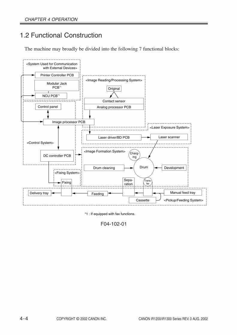
COPYRIGHT © 2002 CANON INC. 2000 2000 2000 2000 CANON iR1200/iR1300 Series REV. 0 AUG. 2002
CHAPTER 4 OPERATION
4-4
1.2 Functional Construction
The machine may broadly be divided into the following 7 functional blocks:
*1 : If equipped with fax functions.
Fixing
Delivery tray
Control panel
DC controller PCB
Image processor PCB
<Control System>
Modular JackPCB*1
NCU PCB*1
Printer Controller PCB
<System Used for Communication with External Devices>
<Fixing System>
Analog processor PCB
Laser driver/BD PCB Laser scanner
Drum
Charg-ing
Development
Trans-fer
Sepa-ration
Feeding
Cassette
Drum cleaning
Manual feed tray
Contact sensor
<Image Reading/Processing System>
<Image Formation System>
<Pickup/Feeding System>
<Laser Exposure System>
Original
F04-102-01

COPYRIGHT © 2002 CANON INC. 2000 2000 2000 2000 CANON iR1200/iR1300 Series REV. 0 AUG. 2002 4-5
CHAPTER 4 OPERATION
1.3 Outline of the Electrical Circuitry1.3.1 Functional Block Diagram
Memb-rane LCD Speaker*2
J7*3/J8*3/J10*4
Tele
phon
e lin
e
To p
ower
sup
ply
Tran
smis
sion
ModularJack PCB*2
Deliverysensor
NCU PCB*2
Fixing assembly
Power supply PCB
Switchingregulator
Cartridge
DC controller PCBFixing heater control block
High-voltage control block
Drive control block
Sensor detection
Image processor PCBinterface block
Laser control block
Horizontal sync signal control
Scanner motor control
Cartridge detection mechanism
Toner level detectionmechanism
Key detectionand LCD/LED
drive
LCDfunction
Serialcommunication
control
Control panelPCB 2-Line/4-Line
conversion circuit
Dial pulse generation
circuit
Line voltageconversion circuit
Off-hook detection
circuit
Image processor PCBDrive control block
Control panel control block
Image processing control block
Sensor detection
Memory function
ESS control
Communication control block
Speaker control*2
J403
J4030 J4020
J402
J401 J1/J2/J6 J103/104 J204/201
J315 J81*2/J320*2/J321*3 J301/302 J303/304
J404
Analogprocessor
PCB
Con
tact
sens
or
Sensor PCB
Reader motor
ADF*1
Lase
r sc
anne
rm
otor
driv
er
Scannermotor
Fan
Man
ual f
eed
pick
upso
leno
id
Man
ual f
eed
tray
pape
r se
nsor
Cas
sette
pic
kup
sole
noid
Lase
r dr
iver
/B
D P
CB
Originalsensor
Registrationsensor
ADF motor
J317
J501
J503
J504
J502
J601
J310
J3102
J311*1
J3112
J3113
J3114
J3110
J316
J801 J3120 J3124 J3081
J312 J309 J307 J314 J308
CommunicationControl
USB serial number notice
function
Smoothing
Printer ControllerPCB
Parallel I/FUSB I/F
J701
J318
J109J7 J206 J252 J251
J2521J651
J202/J203
J106/J108
J205/J207/208/J209J105/J107/
J907*4/J911*3/J912*3
Rec
eptio
nJ1051
PS3
PS102
PS10
PS103
PS11
J652
J6521
PC
PS4
Contact sensor home position
sensor
PS1
ADF(copyboard cover)
open/close sensor
PS2
PS6
PS7
Originaldeliverysensor
PS8
SL2SL1FM1
M4
M3
M2
Mai
n m
otor
driv
er
Mainmotor
J3123
M1
Cassettepaper sensor
Paper leadingedge sensor
PS101LGL paper
sensor
J4 J102*2
Rea
der
unit
slid
ede
tect
ing
switc
h
*1 : If equipped with ADF functions.*2 : If equipped with fax functions.*3 : If equipped with fax functions and 230V model.*4 : If equipped with fax functions and 120V model.
SW1SW2
Sensor relayPCB
J653
J6531
HS
Toner bottle sensor Humidity sensor
Waste toner full sensor
Waste toner full detection function
Tone
r su
pply
cov
erop
en /
clos
e sw
itch
F04-103-01

COPYRIGHT © 2002 CANON INC. 2000 2000 2000 2000 CANON iR1200/iR1300 Series REV. 0 AUG. 2002
CHAPTER 4 OPERATION
4-6
1.3.2 Outlines of Functions1.3.2.1 Image Processor PCB
It controls the machine as a whole, and communicates directly with all PCBs except thesensor PCB and modular jack PCB.
Drive Control BlockThe drive control mechanism acts on the reader motor and the ADF motor by the work of
the ASIC and motor drive IC.
Control Panel Control BlockThe control panel control block receives the state of control keys while sending/receiving
data in serial communication with the control IC of the control panel PCB. Also, it sendsLED and LCD signals to the control panel PCB.
Image Processing Control BlockThe image processing control block has the following functions:
• It subjects the digital image data from the analog processor PCB to enlargement/re-duction processing, shading correction, smoothing, and other image processing,thereby converting it to 600x600-dpi image signals (VD0, VD0*).
• It converts the analog image data from fax communication into 600x600-dpi imagesignals (VD0, VD0*).
• It uses a horizontal sync signal (BD0*) as a trigger to send image signals (VD0,VD0*) to the laser unit.
• The image data from the contact sensor is re-arranged, and the intensity of the contactsensor LED is controlled.
Sensor DetectionIt detects the state of each sensor of the reader unit and the ADF.
ESS ControlIt controls the ESS function used to reduce the power consumption while the machine is
in standby state.
Memory FunctionThe 16MB (as mounted) SDRAM used for the storage of image data is capable of storing
about 255 pages in fax reception made of Canon Fax Standard Chart No.1. The image datais backed up by a vanadium lithium secondary battery (BAT2), so that it remains intact forabout 2 hr after the machine is deprived of power. The 128-KB SRAM is used to store userdata and service data, and is backed up by a lithium battery (BAT1) so that the data may beretained for about 5 yr after the machine is deprived of power.

COPYRIGHT © 2002 CANON INC. 2000 2000 2000 2000 CANON iR1200/iR1300 Series REV. 0 AUG. 2002 4-7
CHAPTER 4 OPERATION
Speaker Control (if equipped with fax functions.)It turns on/off or control the volume of the error sound, key sound, and line monitor
sound generated by the speaker.
Memo
The volume of the line monitor or the sound of the key sound or the errorsound is adjusted in user mode.
Communication Control Block (if equipped with fax functions)The communication control block detects line signals (CNG, DTMF). The 33.6-kps mo-
dem is controlled by the main CPU on the image processor PCB for modulation and de-modulation of transmission/reception data. It also is used to send the DTMF signal.
1.3.2.2 DC Controller PCB
Fixing Heater Control BlockThe fixing heater control block monitors the temperature reading of the thermistor to en-
sure that the temperature of the heater reaches a specific level. If an error is detected in thetemperature of the heater, it stops the power to the heater.
High-Voltage Control BlockThe high-voltage control block controls the high voltage for the primary charging roller,
developing cylinder, transfer charging roller, and fixing film. Of these, the application of DCbias is controlled based on the readings of the humidity around the machine (checked by thehumidity sensor) of the primary charging roller, developing cylinder, and transfer roller.
This mechanism of control is used to increase the bias level in a low humidity environ-ment, thereby improving the reproduction of images.
In a medium to high humidity environment, on the other hand, it serves to save on thelevel of toner consumption.
Drive Control BlockThe drive control block controls the main motor, pickup solenoid, and fan.
Sensor DetectionThe sensor condition of the printer block and the various pickup block are checked to
monitor the drive mechanism and to detect the presence/absence of the cartridge, collectionof waste toner, presence/absence of the toner bottle, and the relative humidity around themachine.
Image Processor PCB Interface blockThe image processor PCB interface block sends the horizontal sync signal (BD0*) to the
image processor PCB. It also returns a state signal in response to a command signal (serial)from the image processor PCB, thereby communicating the state of the printer block to theimage processor PCB.

COPYRIGHT © 2002 CANON INC. 2000 2000 2000 2000 CANON iR1200/iR1300 Series REV. 0 AUG. 2002
CHAPTER 4 OPERATION
4-8
Laser Control BlockThe laser control block controls the drive of the laser diode of the laser scanner unit ac-
cording to the image signals (VD0, VD0*) from the image processor PCB. Also, it controlsthe intensity of the laser diode (auto power control) for each line of print data.
Horizontal Sync Signal ControlWhen the laser beam reaches the horizontal print start position, the laser beam detection
signal (BDI*) from the laser scanner unit is detected, and the horizontal sync signal (BD0*)is sent to the image processor PCB. Also, the horizontal sync signal (BD*) is monitored forfrequency of output.
Scanner Motor ControlThe scanner motor is controlled so that the horizontal resolution of the print image is 600
dpi. Also, the laser beam detection signal (BDI*) from the laser scanner unit is detected tomonitor the rotation of the scanner motor.
Cartridge Detection MechanismIn wait state, the CPU on the DC controller PCB measures the voltage level of the car-
tridge detection signal (CRGSNS) a specific number of times to check the presence/absenceof the cartridge when an AC bias is applied to the primary charging roller.
Toner Level Detection MechanismWhile the machine is in wait state, the toner level detection signal (ADDTNR; based on
the comparison of the developing bias output and the antenna output inside the cartridge)occurring when the developing AC bias is detected during normal rotation to monitor thetoner level inside the cartridge.
1.3.2.3 Control Panel PCB
Key Detection and LCD/LED DriveThe keys are monitored, and the LCD and LEDs are driven.
LCD FunctionThe LCD consisting of 2 lines of 20 characters is controlled according to the display sig-
nals from the image processor PCB.
Serial Communication ControlThe state of the control keys is monitored based on serial communications with the image
processor PCB. LCD and LED drive data are received.
1.3.2.4 Power Supply PCB
Switching RegulatorThe following is generated using power from the power outlet for loads: +24 DC, +12
VDC, +5 VSDC, +5 VDC, +3.3 VSDC, +3.3 VDC.

COPYRIGHT © 2002 CANON INC. 2000 2000 2000 2000 CANON iR1200/iR1300 Series REV. 0 AUG. 2002 4-9
CHAPTER 4 OPERATION
1.3.2.5 Analog Processor PCB
The analog image data read by the contact sensor is converted into digital image data andsent to the ASIC of the image processor PCB.
1.3.2.6 Sensor PCB
The signals from the ADF (copyboard cover) open/close sensor and the contact sensorhome position sensor are sent out to the image processor PCB via the analog processorPCB.
1.3.2.7 Laser Driver/BD PCB
The image signals (VD0, VD0*) from the image processor PCB is converted into dataused for laser adjustment (to cause the laser diode to emit a laser beam). Also, the generatedlaser beam is detected, and the laser beam detection signal (BDI*) is sent to the DC control-ler PCB.
1.3.2.8 Main Motor/Scanner Motor Driver
The main motor/scanner motor is driven according to the drive signals from the DC con-troller PCB.
1.3.2.9 Printer Controller PCB
The communications with the PC are controlled. The image data from the PC is convertedinto print data for the machine, and is sent to the image processor PCB.
Communication ControlCommunications with the PC are controlled using a bi-directional parallel interface (IEEE
std 1284-1994) or USB (Ver. 1.1). The communication protocols used for bi-directionalcommunications include: Nibble, ECP, Rapid Port.
The communication with the image processor PCB by means of a video interface are alsocontrolled.
USB Serial Number Notice FunctionThe USB serial number is communicated to the PC.
SmoothingThe 300 x 300-dpi image data from the PC is converted into image data equivalent of
1200 x 600 dpi; or, 600 x 600-dpi image data is converted into data equivalent of 2400 x600-dpi.

COPYRIGHT © 2002 CANON INC. 2000 2000 2000 2000 CANON iR1200/iR1300 Series REV. 0 AUG. 2002
CHAPTER 4 OPERATION
4-10
1.3.2.10 NCU PCB (if equipped with fax functions)
2-Line/4-Line Conversion CircuitSignals from a 2-line telephone line are converted into 4-line signals (transmission signals
and reception signals). Also, the transmission signals from the image processor PCB areprevented from entering the reception circuit.
Dial Pulse Generation CircuitThe dial pulse generation circuit generates dial pulses by turning on and off the relay in-
side it according to the control signals from the image processor PCB. It then sends the dialsignals to the telephone line by way of the modular jack PCB.
Off-Hook Detection CircuitAn off-hook state is detected with reference to the direct current flowing into the circuit,
occurring when the telephone connected to the telephone terminal of the modular jack PCBis off the hook.
Line Voltage Conversion CircuitThe primary side of the NCU PCB is controlled using a line voltage of +48 VDC. In light
of this, the DC component is cut by the capacitor, and only the audio signals are convertedinto voltages suited to the modem level.
1.3.2.11 Modular Jack PCB (if equipped with fax functions)
The signals from the 2 modular jacks (for telephone line and telephone connection) arecommunicated to the line voltage conversion circuit of the NCU PCB, and the signals fromthe fax are communicated to the telephone line.
1.3.2.12 Sensor Relay PCB
Relay the connection between the DC controller PCB and the sensors below• Humidity sensors (HS)• Toner bottle sensor (PS11)

COPYRIGHT © 2002 CANON INC. 2000 2000 2000 2000 CANON iR1200/iR1300 Series REV. 0 AUG. 2002 4-11
CHAPTER 4 OPERATION
1.4 Power-On Sequence
The following is the flow of operation occurring from when the machine is turned on un-til it enters standby state:
Standby
Power-On
Initializes the CPU, Clears the RAM, Sets the Port
Starts communication with the image processor PCB.
• Checks the reader unit (open/close).• Toner supply cover open/closed detection• Toner bottle present/absent detection• Checks paper (cassette, manual tray).• Detects size of paper (LGL; cassette).• Checks the thermistor (open/short).
Fixing Heater On
The primary charging AC/DC bias, Transfer Cleaning Bias ON
The developing AC/DC bias goes ON.
The primary charging DC bias and developing AC/DC bias go OFF.
The main motor and primary charging AC bias go OFF.
The transfer cleaning bias goes OFF.
Auto delivery occursif the paper leading edge sensor detects paper.
A jam is identified if the paper leading edge sensor or the delivery sensor detects paper.
Checks the machine inside for residual paper.
NO
YES
0.2 sec after the fixing heater goes ON,is the fixing temperature 100˚C ? Or, has 0.5 secpassedafter the fixing heater went ON?
A check is made for the presence/absence of a cartridgewhen the primary charging AC bias is applied.
The toner level is checked when the developing bias is applied.
Fixing Heater OFFMain Motor ON
When the main motor goes ON, the machine always checks the level of waste toner.
F04-104-01

COPYRIGHT © 2002 CANON INC. 2000 2000 2000 2000 CANON iR1200/iR1300 Series REV. 0 AUG. 2002
CHAPTER 4 OPERATION
4-12
1.5 Controlling the Main Motor1.5.1 Outline
The rotation of the machine’s main motor (M1) is controlled by the drive signal (MON)generated by the DC controller PCB.
The machine keeps the following ON at all times using the drive of the main motor,thereby moving paper at the selected printing speed:
• vertical path roller• registration roller• primary charging roller• developing cylinder• photosensitive drum• transfer charging roller• fixing pressure roller• delivery roller
The machine uses the activation of the cassette pickup solenoid or the manual feed pickupsolenoid as a trigger (occurring when the main motor is ON) to drive the following pickuprollers for a specific period of time:
• cassette pickup roller• manual feed pickup roller
Main motor
Primary charging roller
Photosensitivedrum
Developing cylinder
Manual feed pickup roller
Deliveryroller
Fixingpressureroller
Cassette pickup roller
Vertical path roller
Registration rollerTransfer charging roller
F04-105-01

COPYRIGHT © 2002 CANON INC. 2000 2000 2000 2000 CANON iR1200/iR1300 Series REV. 0 AUG. 2002 4-13
CHAPTER 4 OPERATION
2 Image Reading/Processing System
2.1 Outline
The image reading/processing system consists of the following major components:• contact sensor used to read originals• reader motor, drive pulley, drive belt, carriage, and carriage rail used to move the con-
tact sensor• The analog processor PCB is used to convert the analog image data colleted by the
contact sensor into digital image data.
The image reading mechanism is controlled based on the drive signals from the imageprocessor PCB, thereby moving the contact sensor to read the original placed on thecopyboard glass. (F04-201-01)
When the ADF is used, the contact sensor is moved to stream reading position, and theoriginals are read when they are moved by the ADF.
Analog processor PCB
Contact sensor
Drive belt
Drive pulleys
Drive pulley
Carriage railReader motor
Contact sensor home position sensor
(forward)
(reverse)
Stream reading position with ADF in use
Carriage
Drive belt
F04-201-01

COPYRIGHT © 2002 CANON INC. 2000 2000 2000 2000 CANON iR1200/iR1300 Series REV. 0 AUG. 2002
CHAPTER 4 OPERATION
4-14
3 Laser Exposure System
3.1 Outline
The laser scanner unit consists of the following major components:• laser unit, which serves as the source of laser beam.• laser scanner motor, equipped with a 4-face mirror for laser scanning.• laser driver/BD PCB used to detect laser beam or to control emission of laser beam.
The laser beam generated by the laser unit based on the signals from the DC controllerPCB moves through the collimator lens (inside the laser unit) and the cylindrical lens toreach a 4-face polygon mirror rotating at a constant speed.
When reflected by the 4-face polygon mirror, the laser beam moves through the imaginglens, and is bent by the reflecting mirror to reach the photosensitive drum. At this time, thelaser beam also is directed to the BD circuit of the laser driver/BD PCB. (F04-301-01)
As the 4-face polygon mirror rotates at a constant speed, the laser beam scans the surfaceof the photosensitive drum at a constant speed, thereby removing charges and forming staticimages.

COPYRIGHT © 2002 CANON INC. 2000 2000 2000 2000 CANON iR1200/iR1300 Series REV. 0 AUG. 2002 4-15
CHAPTER 4 OPERATION
Reflecting mirror
Laser driver/BD PCB
• copy image data• print image data• fax image data (if equipped with fax functions)
Cylindrical lens
4-face mirror
DC controller PCB
Laser driver block
Photosensitive drum
Laser scanner motor
Laser unit
BD block
Imaging lens
Laser beam
detection signal
(BD
I*)
Imag
e si
gnal
(VD
O,V
DO
*)
Lase
r sc
anne
rm
otor
driv
e si
gnal
Lase
r dr
iver
cont
rol s
igna
lC
omm
unic
atio
nco
ntro
l
Hor
izon
tal
sync
sig
nal
Image processor PCB
F04-301-01

COPYRIGHT © 2002 CANON INC. 2000 2000 2000 2000 CANON iR1200/iR1300 Series REV. 0 AUG. 2002
CHAPTER 4 OPERATION
4-16
4 Image Formation System
4.1 Outline
F04-401-01 shows the construction of the image formation system.The machine is a cartridge type, in which the core of its image formation components are
constructed as a signal entity: photosensitive drum, primary charging roller, developing cyl-inder, cleaning blade, and toner housing.
The DC controller PCB has a built-in high-voltage output assembly, and generates highvoltage for charging at such times as necessary.
High-voltageoutput block
DC controller PCBCartridge
Primarycharging roller
Cleaning blade
Staticeliminator
Transfer chargingroller
DevelopingcylinderDrum
J205
J207
J208
J209
Transfer guide
F04-401-01
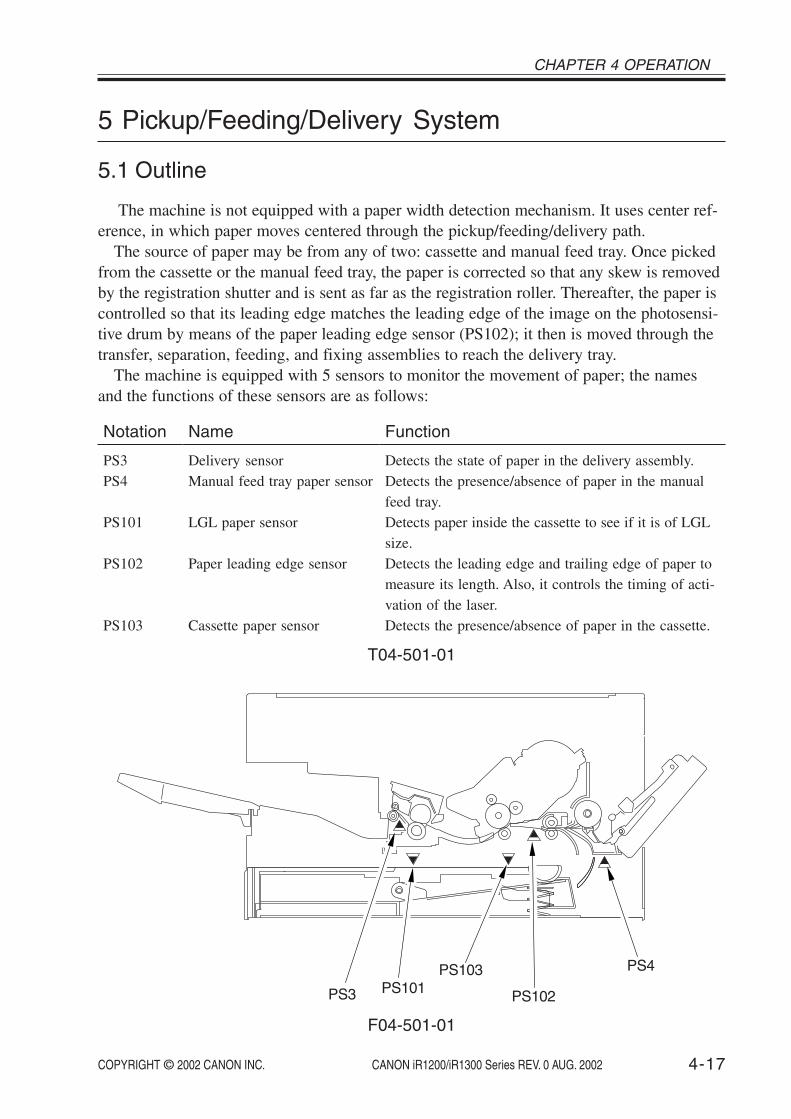
COPYRIGHT © 2002 CANON INC. 2000 2000 2000 2000 CANON iR1200/iR1300 Series REV. 0 AUG. 2002 4-17
CHAPTER 4 OPERATION
5 Pickup/Feeding/Delivery System
5.1 Outline
The machine is not equipped with a paper width detection mechanism. It uses center ref-erence, in which paper moves centered through the pickup/feeding/delivery path.
The source of paper may be from any of two: cassette and manual feed tray. Once pickedfrom the cassette or the manual feed tray, the paper is corrected so that any skew is removedby the registration shutter and is sent as far as the registration roller. Thereafter, the paper iscontrolled so that its leading edge matches the leading edge of the image on the photosensi-tive drum by means of the paper leading edge sensor (PS102); it then is moved through thetransfer, separation, feeding, and fixing assemblies to reach the delivery tray.
The machine is equipped with 5 sensors to monitor the movement of paper; the namesand the functions of these sensors are as follows:
Notation
PS3PS4
PS101
PS102
PS103
Name
Delivery sensorManual feed tray paper sensor
LGL paper sensor
Paper leading edge sensor
Cassette paper sensor
Function
Detects the state of paper in the delivery assembly.Detects the presence/absence of paper in the manualfeed tray.Detects paper inside the cassette to see if it is of LGLsize.Detects the leading edge and trailing edge of paper tomeasure its length. Also, it controls the timing of acti-vation of the laser.Detects the presence/absence of paper in the cassette.
T04-501-01
PS4
PS102
PS103
PS3 PS101
F04-501-01

COPYRIGHT © 2002 CANON INC. 2000 2000 2000 2000 CANON iR1200/iR1300 Series REV. 0 AUG. 2002
CHAPTER 4 OPERATION
4-18
5.2 Pickup Operation5.2.1 Pickup from the Cassette5.2.1.1 Outline
Paper is picked up from the cassette under the control of the CPU on the DC controllerPCB and using the drive of the main motor (M1). When the cassette pickup solenoid (SL2)goes ON, the drive of the main motor (M1) is transmitted to the cassette pickup roller as-sembly to rotate the cassette pickup roller.
When the cassette pickup roller rotates, a single sheet of paper is separated from the stackby the separation claws of the cassette, and is sent as far as the registration shutter by way ofthe vertical path roller.
Cassette pickup rollersGear A
Gear B
Paper
SL2
Spring
Cas
sette
pic
k so
leno
id d
rive
sign
al
DC controller PCB
Main motor
When SL2 goes ON, the spring will turnthe pickup roller slightly with the resultthat the gear A engages with the gear B.
F04-502-01

COPYRIGHT © 2002 CANON INC. 2000 2000 2000 2000 CANON iR1200/iR1300 Series REV. 0 AUG. 2002 4-19
CHAPTER 4 OPERATION
5.2.1.2 Retry Pickup
If the paper leading edge sensor (PS102) does not detect paper within a specific period oftime after the cassette pickup roller has started to rotate, the machine will start to rotate thecassette pickup roller once again to execute a retry pickup operation.
If the paper leading edge sensor (PS102) still does not detect paper within a specific pe-riod of time after the machine executes a retry pickup operation once, the machine will iden-tify the condition as a jam and will indicate a jam message on the LCD.
5.2.1.3 Detecting the Size of Paper
The machine detects the size of paper in the cassette in any of two ways: LGL size detec-tion and non-LGL size detection.
LGL detection is performed by means of a LGL paper sensor (PS101). The LGL size de-tection mechanism is used to prevent picking up a subsequent sheet of paper before the trail-ing edge of paper leaves the cassette, otherwise occurring if the pickup was let to occur atthe same time using other sizes when picking up LGL paper.
Non-LGL detection is performed using the paper leading edge sensor (PS102) based onthe length of paper. In fax mode, if paper of a size different from the size selected from thecontrol panel is placed, the DC controller will identify a paper size mismatch at the end ofprinting and indicate a message on the LCD.

COPYRIGHT © 2002 CANON INC. 2000 2000 2000 2000 CANON iR1200/iR1300 Series REV. 0 AUG. 2002
CHAPTER 4 OPERATION
4-20
5.2.2 Pickup from the Manual Feed Tray5.2.2.1 Outline
Paper is picked up from the manual feed tray under the control of the CPU on the DCcontroller PCB and using the drive of the main motor (M1). When the manual feed pickupsolenoid (SL1) goes ON, the drive of the main motor (M1) is transmitted as far as themanual feed pickup roller assembly to rotate the manual feed pickup roller.
The sheets of paper stacked in the manual feed tray are lifted by the work of a spring andforced against the manual feed pickup roller. Thereafter, a single sheet of paper is separatedby the work of the manual feed pickup roller and the separation pad, and is moved as far asthe registration shutter.
Main motor
Gear AGear B
Manual feed tray pickupsolenoid drive signal
Manual feed traypickup roller
Cam
When SL1 goes ON, the spring moves up to push upthe cam, causing the manual feed pickup roller torotate slightly; as a result, the gear A and the gear Bbecome engaged.
DC controller PCB
SL1
F04-502-02
COPYRIGHT © 2002 CANON INC. 2000 2000 2000 2000 CANON iR1200/iR1300 Series REV. 0 AUG. 2002 4-21
CHAPTER 4 OPERATION
5.2.2.2 Retry Pickup
If the paper leading edge sensor (PS102) does not detect paper within a specific period oftime after the manual feed pickup roller starts to rotate, the machine will rotate the manualfeed pickup roller once again to execute a retry pickup operation. If the paper leading edgesensor (PS102) still does not detect the leading edge of paper after the machine executes aretry pickup operation once, the machine will identify the condition as a jam and will indi-cate a jam message on the LCD.
5.2.2.3 Detecting the Size of Paper
The size of paper in the manual feed tray is detected using the paper leading edge sensor(PS102) with reference to the length of paper. In fax mode, if paper of a size different fromthe size selected from the control panel is placed, the DC controller will identify a paper sizemismatch at the end of printing and indicate a message on the LCD.

COPYRIGHT © 2002 CANON INC. 2000 2000 2000 2000 CANON iR1200/iR1300 Series REV. 0 AUG. 2002
CHAPTER 4 OPERATION
4-22
5.3 Feeding Operation/Delivery Operation5.3.1 Outline
The machine uses the following to feed/deliver paper:• registration roller• photosensitive drum• transfer charging roller• fixing pressure roller• delivery roller
The paper moved as far as the registration shutter by the work of the various pick opera-tions is corrected for skew movement when it is butted against the registration roller.
When the paper moves past the registration assembly, the paper leading edge sensor(PS102) detects its leading edge, thereby ensuring that the leading edge of the paper willmatch the leading edge of the image on the photosensitive drum. Thereafter, the paper ismoved past the photosensitive drum and then is moved over the transfer charging roller, fix-ing pressure roller, and delivery roller.
Paper
Resistrationshutter
F04-503-01
5.3.2 Auto Delivery Control
The machine drives the main motor (M1) for a specific period of time to feed/deliveryroller when the power is turned on, when the reader unit is returned to its initial position, orwhen it shifts from ESS mode, in addition to the following:a. after starting the main motor (M1), the paper leading edge sensor (PS102) detects paper.b. the size of the paper delivered last is B5 or smaller, and the delivery sensor (PS3) detects
paper after the main motor (M1) is started.

COPYRIGHT © 2002 CANON INC. 2000 2000 2000 2000 CANON iR1200/iR1300 Series REV. 0 AUG. 2002 4-23
CHAPTER 4 OPERATION
5.4 Reducing the Copying Speed5.4.1 Outline
The machine is not equipped with a paper width detection mechanism; for this reason, ifpaper with a limited width is used in continuous printing, the ends of the fixing heaterwould overheat. To prevent overheating, the machine switches among 3 copying speeds withreference to the readings of the sub thermistor.
1. Normally, the machine reduces the speed to 4 ppm when the reading of the sub ther-mistor reaches 245°C/473°F or higher.
2. The machine will further reduce the copying speed to 3 ppm if the reading of the subthermistor reaches 255°C/491°F or higher after it has reduced it to 4 ppm.
3. The machine will further reduce the copying speed to 2 ppm if the reading of the subthermistor reaches 260°C/500°F or higher after it has reduced it to 3 ppm.

COPYRIGHT © 2002 CANON INC. 2000 2000 2000 2000 CANON iR1200/iR1300 Series REV. 0 AUG. 2002
CHAPTER 4 OPERATION
4-24
5.5 Detecting Jams5.5.1 Outline
The machine is equipped with 6 sensors used to detect jams.The presence/absence of paper is checked with reference to the state of each sensor at
such times as stored in the CPU on the DC controller PCB. When the machine detects a jam,it will turn off the main motor (M1) and will indicate a jam message on the LCD.
5.5.2 Types of Jams
The machine groups jams into 8 types. When a jam occurs, be sure to remove it, and startover the operation.
a.Pickup Delay JamAfter execution of a pickup retry, the paper leading edge sensor (PS102) does not detect
the leading edge of paper within a specific period of time, or no paper exists at time of apickup retry.
b. Paper Leading Edge Sensor Stationary JamAfter the paper leading edge sensor (PS102) has detected the leading edge of paper, the
paper leading edge sensor (PS102) does not detect the trailing edge of paper within a spe-cific period of time.
c. Delivery Sensor Leading Edge Delay JamAfter the paper leading edge sensor (PS102) has detected the leading edge of paper, the
delivery sensor (PS3) does not detect the trailing edge of paper within a specific period oftime.
d.Fixing Wrap JamAfter the delivery sensor (PS3) has detected the leading edge of paper, the delivery sensor
(PS3) detects the absence of paper before a specific period of time.
e.Delivery Sensor Trailing Edge Delay JamAfter the delivery sensor (PS3) has detected the leading edge of paper, the delivery sensor
(PS3) does not detect the trailing edge of paper within a specific period of time.
f. Delivery Sensor Stationary Jam• As part of operation after a pickup delay jam, the delivery sensor (PS3) detects the
trailing edge of paper; however, the delivery sensor (PS3) once again detects the trail-ing edge of paper, the laser is forced OFF, and a specific period of time passes.
• As part of operation after a pickup delay jam, the delivery sensor (PS3) detects paper,the laser is forced OFF, and a specific period of time passes.
• At time of cleaning the fixing pressure roller, the trailing edge of paper does not movepast the delivery sensor (PS3; i.e., the sensor does not go OFF) within a specific pe-riod of time.

COPYRIGHT © 2002 CANON INC. 2000 2000 2000 2000 CANON iR1200/iR1300 Series REV. 0 AUG. 2002 4-25
CHAPTER 4 OPERATION
g.Auto Delivery Jam• When the fixing heater is started, the paper leading edge sensor (PS102) detects the
presence of paper.• The paper group is not known or the paper last subjected to length detection is identi-
fied as being LTR or larger; under either of these conditions, the delivery sensor (PS3)detects paper within 2 sec after the fixing heater starts.
• The size of the paper last subjected to length detection is identified as being LTR orlarger, and the delivery sensor (PS3) detects paper within 2 sec after the main motorstarts.
• While auto delivery is under way, the machine identifies the absence of a cartridge.
h.Door Open Jam• During printing, the reader unit slide detecting switch (SW1) has detected movement
(sliding) for the reader unit.• If the toner supply cover open/closed detecting switch (SW2) identifies the toner
bottle cover as being open during printing.• If the toner bottle sensor (PS11) identifies the toner bottle as being displaced during
printing.
SW1 (for jam h)Presence/absence of cartridge(for jam g; developing bias)
PS3 (for jam c, d, e, f, or g) PS103 (for jam a)PS4 (for jam a)
PS102 (for jam a, b, or g)
SW2(for jam h)
F04-505-01

COPYRIGHT © 2002 CANON INC. 2000 2000 2000 2000 CANON iR1200/iR1300 Series REV. 0 AUG. 2002
CHAPTER 4 OPERATION
4-26
6 Fixing System
6.1 Outline
The fixing pressure roller and the delivery roller are driven by the main motor.The paper separated from the photosensitive drum is moved to the inside of the fixing as-
sembly; the paper is then moved outside it after the toner is fused to the paper by the workof the fixing film and the fixing pressure roller.
The delivery sensor (PS3) is used to detect paper coming out of the fixing assembly.
Fixing heaterFixing filmDelivery roller
Delivery sensor (PS3) Fixing pressure roller
Fixing inlet guide
F04-601-01
Fixing pressure roller
Main thermistor (TH1)
Sub thermistor (TH2)
Thermal fuse (FU2)
Fixing film
Fixing heater (H1)
F04-601-02

COPYRIGHT © 2002 CANON INC. 2000 2000 2000 2000 CANON iR1200/iR1300 Series REV. 0 AUG. 2002 4-27
CHAPTER 4 OPERATION
6.2 Controlling the Fixing Operation6.2.1 Controlling the Fixing Temperature
The fixing film unit has a plate-shaped fixing heater built into it for heating the fixingfilm.
The fixing heater is equipped with 2 thermistor: a main thermistor in the middle and a subthermistor at the end. The main thermistor is used to control the temperature of the fixingheater and to detect its overheating, while the sub thermistor is used to detect an error tem-perature on the end of the fixing heater.
The CPU on the DC controller PCB monitors the main thermistor signal (FSRTH) and thesub thermistor signal (SUBTH) from the thermistors for control of the fixing heater drivesignal (FSRD0) and the relay drive signal (RLYD), thus varying the supply of power to theheater and, ultimately, controlling the temperature of the fixing heater.
Fixing assembly
Fixingheater
Subthermistor
Mainthermistor
DC controller PCB
Power supply PCB
SUBTH
FSRTHCPU
+3.3V
FSRDO
RLYD
+24V
Image processor PCB
Fixing heater high tempe-rature error detection
F04-602-01

COPYRIGHT © 2002 CANON INC. 2000 2000 2000 2000 CANON iR1200/iR1300 Series REV. 0 AUG. 2002
CHAPTER 4 OPERATION
4-28
The CPU on the DC controller PCB executes the following 4 types of fixing temperaturecontrol:
• Start-Up Temperature ControlIn response to a print command from the image processor PCB, the temperature of the
fixing heater is started up to a level 15°C/59°F lower than paper passage control temperaturetarget.
• Paper Passage Temperature ControlWhile printing is taking place, the fixing heater temperature is controlled so that it is iden-
tical with the paper passage control temperature target.
• Sheet-to-Sheet Temperature ControlTo prevent overheating of areas not covered by paper (between sheets), the fixing heater
temperature is controlled to a level relatively lower than the paper passage control tempera-ture target.
• Rest Heating Temperature ControlWhile the machine is at rest, the fixing pressure roller is heated so that the toner collecting
on it is melted and moved to the fixing film, thereby ridding the roller of toner.The rest heating control mechanism is used to control the temperature of the fixing heater
to a level lower than the paper passage target level when LTR or larger paper is used forprinting.
The control temperature targets are switched in reference to the following 4 conditions:• paper type (as indicated by a command during printing)• type of control (cover paper or between sheets)• change in fixing temperature control (OFF → start-up → paper passage, etc.)• count of prints in continuous mode

COPYRIGHT © 2002 CANON INC. 2000 2000 2000 2000 CANON iR1200/iR1300 Series REV. 0 AUG. 2002 4-29
CHAPTER 4 OPERATION
6.2.2 Controlling the Fixing Film Bias
The machine is equipped with a fixing film bias control mechanism which is controlledby the CPU on the DC controller PCB. The fixing film bias is used to prevent displacementof toner deposits; i.e., when the primary charging roller DC bias is applied, a bias of thesame polarity as the toner is applied to the fixing film so as to create a magnetic field be-tween the paper and the film.
Primary charging roller
CPU
DC controller PCB
SuperpositionJ205
Primary chargingrollerDC bias drive circuit
Primary chargingrollerAC bias drive circuit
J206Fixing film
Photosensitivedrum
F04-602-02
6.2.3 Fixing Heater Safety Mechanism
The fixing heater safety circuit is part of the DC controller PCB, and is used to monitorthe fixing temperature for an error at all times. If the output voltage for the main thermistoror the sub thermistor reaches about 0.37 V or lower (about 310°C/590°F), the relay will beturned off regardless of the state of the relay drive signal (RLYD) from the CPU to shut thepower to the fixing heater.
If the temperature of the fixing heater increases abnormally, on the other hand, to exceedabout 230°C/446°F, the thermal fuse will melt to cut the power to the fixing heater.
6.2.4 Detecting a Fault in the Fixing Assembly
The CPU on the DC controller PCB will identify a fault in the fixing assembly if any ofthe following conditions (a through f) occurs; as a result,
• it will cut the power to the fixing heater.• it will cause the relay drive signal (RYLD) to go ‘1’ to turn off the relay and, at the
same time, will communicate the presence of a fault to the image processor PCB.

COPYRIGHT © 2002 CANON INC. 2000 2000 2000 2000 CANON iR1200/iR1300 Series REV. 0 AUG. 2002
CHAPTER 4 OPERATION
4-30
a.Overheating 1 (all conditions)The CPU will identify overheating 1 if the main thermistor detects 230°C/446°F for 1 sec
or more continuously.
b. Start-Up Error 1 (start-up)The CPU will identify start-up error 1 if a level of temperature lower than 120°C/248°F is
detected for 1 sec or more continuously 10 sec after the heater is supplied with power.
c. Start-Up Error 2 (startup/paper passage)The CPU will identify start-up error 2 if a level of temperature 15°C/59°F lower than the
paper passage temperature control target is not detected at all 75 sec after the heater is sup-plied with power.
d.Temperature Control Low Temperature Error (paper passage/sheet-to-sheet/restheating/temperature control)The CPU will identify a temperature control low condition error if a level of temperature
lower than 120°C/248°F is detected for 1 sec or more continuously in paper passage, sheet-to-sheet, rest heating, or temperature control state.
e.Main thermistor Open Circuit (all conditions)The CPU will identify main thermistor open circuit if the A/D conversion value of the
output voltage from the main thermistor is in excess of a specific value for 1 sec or more.
f. Overheating 2 (all conditions)The CPU will identify overheating 2 if the sub thermistor detects 300°C/572°F or higher
for 0.2 sec over more continuously.
g. Sub Thermistor Error Low Temperature 1 (warm-up)The CPU will identify sub thermistor error low temperature 1 if the temperature reading is
lower than 75°C/167°F for 1 sec or more 10 sec after the heater is first supplied with power.
h.Sub Thermistor Error Low Temperature 2 (cool-down)The CPU will identify sub thermistor error low temperature 2 if all the following condi-
tions exit when the heater is off after printing ends and the trailing edge of the paper movespast the delivery sensor.
• the thermistor reading is lower than 75°C/167°F when the heater is off.• printing has not been cancelled in the middle.• no error has occurred during printing.• the thermistor reading is lower than 75°C/167°F before the trailing edge of the paper
moves past the delivery sensor.
COPYRIGHT © 2002 CANON INC. 2000 2000 2000 2000 CANON iR1200/iR1300 Series REV. 0 AUG. 2002 4-31
CHAPTER 4 OPERATION
7 Power Supply System
7.1 Low Voltage Circuit7.1.1 Low Voltage Power Supply Circuit
The machine’s DC power supply is generated by the power supply PCB.The AC power arriving at the power supply PCB is converted into the following for sup-
ply to loads: +3.3 VDC, +3.3 VSDC, +5 VDC, +5 VSDC, +12 VDC, +24 VDC.See the following for an outline of the DC power supply:
Output voltage
+3.3V+3.3VS*1
+5.1V+5.1VS*1
+12V+24V
Output voltage value
+3.4V ± 3%+3.4V ± 3%+5.1V ± 4%+5.1V ± 4%+12V ± 5%+24V ± 5%
*1: Also supplied during ESS mode.
T04-701-01

COPYRIGHT © 2002 CANON INC. 2000 2000 2000 2000 CANON iR1200/iR1300 Series REV. 0 AUG. 2002
CHAPTER 4 OPERATION
4-32
Analog processor
PCB
Laser scanner unit
Solenoids
Main motor
Control panel PCB
NCU PCB*2
ADF unit*1
ADF motor
ADF sensors
Reader unitslide detecting
switch
Reader motor
Sensors
P1NF
Power supply PCB
F2F1
Low-voltage power supply circuit
+3.3 V circuit
+ 5 V circuit
+12 V circuit
+24 V circuit+24V
+12V
+5VS+5V
+3.3VS+3.3V
F101
+3.3V
+8V
+3.3V+5V
+24V
+24V
+24V
+3.3V
+5VS
Modular jack PCB*2
Contact sensor
Sensor PCB+5V
+8V
+24V
+3.3V
+3.3VS+12V
+5V
+24V
+5V
*1 : Only if equipped with ADF functions.*2 : Only if equipped with fax functions.
DC controller PCB
• Cassette paper sensor• Paper leading edge sensor• LGL paper sensor
Fan
Manual feed traypaper sensor
+3.3V
+3.3V
+24V
+24V
Printer controllerPCB
+3.3VS
+5VS
+24V+5V
+3.3V
Imag
e pr
oces
sor
PC
B
Toner supply coveropen/close
switch
+24V
Waste tonerfull sensor
+3.3V +3.3VSensor relayPCB
• Humidity sensor• Toner bottle sensor
+3.3VDelivery Sensor
F04-701-01

COPYRIGHT © 2002 CANON INC. 2000 2000 2000 2000 CANON iR1200/iR1300 Series REV. 0 AUG. 2002 4-33
CHAPTER 4 OPERATION
7.1.2 Protective FunctionsThe power supply PCB is equipped with an over-current/over-voltage protection mecha-
nism to prevent damage to the power circuit in the event of an over-current or over-voltage,as caused by a short circuit or the like on the load side. If the over-current/over-voltage pro-tective mechanism has gone ON, disconnect the power cord, and correct the fault; then, con-nect the power cord once again to reset the machine. If short circuiting and resetting are re-peated, the internal fuse (F1, F2, F101) can melt.
7.2 High-Voltage Power Supply CircuitThe high voltage output circuit is built into the DC controller PCB.The CPU on the DC controller PCB sends instructions for the generation of the following
high voltages at specific timing:• primary charging roller bias (AC voltage + DC negative voltage)• developing bias (AC voltage + DC negative voltage)• transfer charging roller bias (DC positive voltage or DC negative voltage)
7.3 Controlling the ESS Mechanism7.3.1 Outline
The machine is equipped with an ESS mechanism to limit the consumption of power instandby as much as possible. The ESS function is controlled by the image processor PCB,and the machine shifts to ESS mode when the Energy Saver key in the control panel ispressed or the machine remains in standby state for a specific period of time.
The standby period after which the ESS mode is started is set in user mode: 3 to 30 min(factory default: 5 min).
7.3.2 OperationWhile the machine remains in ESS mode, all in the control panel except the LED indica-
tor of the Energy Saver key will remain OFF. The machine will not shift to ESS mode underany of the following conditions:
• The shift to ESS mode is not enabled in user mode.• A jam or a service error occurred, and the Alarm lamp is ON. (In the case of the ab-
sence of toner or paper, full of the waste toner, and the machine shifts to ESS mode inthe absence of paper.)
• The image memory contains image data. *1
While the machine is in ESS mode, it will shift out of the state in response to a press onthe Energy Saver key; in addition, it will automatically shift out of the state under any of thefollowing conditions:
• Print data arrives from the PC.• A fax arrives. *1
• Off-hook state is detected. *1
• A report output time occurs. *1
• A timer call time occurs. *1
*1: Only if equipped with fax functions.

COPYRIGHT © 2002 CANON INC. 2000 2000 2000 2000 CANON iR1200/iR1300 Series REV. 0 AUG. 2002
CHAPTER 4 OPERATION
4-34
8 Others
8.1 Fan8.1.1 Outline
The machine is equipped with a single fan at the rear of the delivery assembly to cool thelaser scanner unit, to discharge heat from around the fixing assembly, to cool the elementsof the PCBs, and to discharge ozone.
The fan is controlled by the CPU on the DC controller PCB for the following:
• full-speed rotation while the main motor is in operation.• full-speed rotation for 30 sec and half-speed rotation for 60 sec after the main motor
stops.• full-speed rotation for 30 sec and half-speed rotation for 60 sec during WAIT.
The CPU on the DC controller PCB generates the fan drive signal (FANON) based on thestate of the fan stop signal (FANSTOP; 0: reset, 1: rotate) and the full-speed/half-speedswitch signal (FANHALF; 0: half-speed, 1: full-speed) to control the fan rotation to any ofthree: rest, half-speed, full-speed.
• Power supply PCB• DC controller PCB
Fixing assemblyCartridge
Main motor
Laser scanner unit
F04-801-01

COPYRIGHT © 2002 CANON INC. 2000 2000 2000 2000 CANON iR1200/iR1300 Series REV. 0 AUG. 2002 4-35
CHAPTER 4 OPERATION
8.2 Back-Up Batteries8.2.1 Back-Up Function8.2.1.1 Outline
The machine’s image processor PCB is equipped with a lithium battery (BAT1) and a va-nadium lithium secondary battery (BAT2) for back-up of the data in the SRAM and theSDARM in consideration of a power outage or when the power is turned off.
The batteries must be replaced correctly to avoid explosion.Do not replace any battery with one not indicated for the machine, i.e., useone of the same type or equivalent.Be sure to dispose of used batteries according to local laws and regulations.
8.2.1.2 Lithium Battery (BAT1)
The data backed up in the SRAM by the lithium battery (BAT1) contains user data for faxfunctions, communications control data, and service mode settings.
Battery life: about 5 yr
The LCD will indicate ‘DATA ERROR’ when the power is tuned on after the lithium bat-tery (BAT1) has reached the end of its life. If such a condition has occurred, be sure to re-place the image processor PCB according to the instructions given in 1.4.1 of Chapter 7.
If you disconnect the jumper plug (JP1) of the image processor PCB andturn off the power, all control data will be reset to default settings. Do notdisconnect the jumper plug (JP1) to prevent the loss of data.
Memo
The pin of the jumper plug (JP1) is displaced on the image processor PCBavailable as a service part so as to prevent exhaustion of the lithium battery(BAT1).

COPYRIGHT © 2002 CANON INC. 2000 2000 2000 2000 CANON iR1200/iR1300 Series REV. 0 AUG. 2002
CHAPTER 4 OPERATION
4-36
Vanadium lithiumsecondary battery
(BAT2)
Lithium battery(BAT1)
Jumper plug(JP1)
F04-802-01

COPYRIGHT © 2002 CANON INC. 2000 2000 2000 2000 CANON iR1200/iR1300 Series REV. 0 AUG. 2002 4-37
CHAPTER 4 OPERATION
8.2.1.3 Vanadium Lithium Secondary Battery (BAT2)
The data backed up by the vanadium lithium secondary battery (BAT2) is image data usedfor fax transmission/reception, and it does not include the image data for memory copying.
Back-up time: about 2 hr (assuming that the machine is kept ON for 5 day or more un-der normal temperature/pressure conditions)
Battery life: about 5 yr or after repeating charging and discharging 40 times at 100%
If the backup data cannot be stored longer than half the indicated period (even after themachine has been powered for 5 day or longer under normal temperature and atmosphericconditions), suspect that the battery has reached the end of its life.
If the foregoing back-up time is exceeded, the image data stored inSDRAM will be lost. To prevent loss of image data for service work or re-location, be sure to print out the image data stored in SDRAM before start-ing the work.
Memo
Memory Clear ListIf the memory clear list is automatically printed when the machine is turnedon, the image data indicated on the list is the data that was lost withoutback-up. After the list is printed, the image data storage and the control in-formation will automatically be deleted. The following is a sample of thememory clear list:
0002000200020002
1111
DELAYED TXDELAYED TXMEMORY RXMEMORY RX
07/30 13:5107/30 13:5107/30 13:5307/30 13:54
13:5913:51----------
07/30/2001 17:52 FAX 001
MEMORY FILES DELETED
TX/RX NO MODE DESTINATION TEL/ID PGS. SET TIME ST. TIME
* * * * * * * * * * * * * * * * * * **
*
***
* *
*
*
***
*** * * * * * * * * * * * * * * * * * *
***
***
MEMORY CLEAR REPORT
F04-802-02

COPYRIGHT © 2002 CANON INC. 2000 2000 2000 2000 CANON iR1200/iR1300 Series REV. 0 AUG. 2002
CHAPTER 4 OPERATION
4-38
8.2.2 Back-Up Data8.2.2.1 Types of Data
The types of data backed up by the data back-up lithium batteries (BAT1, BAT2) on theimage processor PCB are as follows: a, b, and c are stored in the SRAM (backed up byBAT1), while d is the data stored in the SDRAM (backed up by BAT2).
a.User Data
Description
(various settings of reception/transmission mode)(one-touch dial, etc)
1. data register2. telephone number register
Item
register/set
T04-802-02
Description
error control, echo remedy, etc.NL equalizer, transmission level, etc.FAX/TEL switch parameter, etc.not used normallynot used normallynot used normallynot used normallyimage position adjustment, etc.reduction, etc.malfunctionreading counter, print counter, etc.system dump list, key history report output, etc.malfunctionvarious data initialization, etc.version No., checksum, etc.malfunction
Item
#1.#2.#3.#4A.#4B.#4C.#5.#6.#7.#8.#9.#10.#11.#12.#13.#14.
SSSWMENUNUMERIC ParamSPECIALNCUISDNTYPESCANNERPRINTERPDLCOUNTERREPORTDOWN LOADCLEARROMCS SET
T04-802-01
b. Service Mode Data

COPYRIGHT © 2002 CANON INC. 2000 2000 2000 2000 CANON iR1200/iR1300 Series REV. 0 AUG. 2002 4-39
CHAPTER 4 OPERATION
T04-802-03
d.Data Backed Up by BAT2
Item
communication control recordsystem dump record
Description
most recent 20 communications (reception/transmission)past communications state, error communication history, etc.
T04-802-04
c. Control Data
Item
Transmission image
reception image
Description
transmission (memory transmission, broadcast)timer transmissiontimer broadcastmemory reception

COPYRIGHT © 2002 CANON INC. 2000 2000 2000 2000 CANON iR1200/iR1300 Series REV. 0 AUG. 2002
CHAPTER 4 OPERATION
4-40
T04-802-06
c. Control Data
T04-802-07
8.2.2.2 Printing the Backup Data List
The data baked up in control memory may be printed in the form of a list.
If you are replacing the image processor PCB, be sure to print out the list inadvance. For the method of printing, see 2.2 or 3.21 of Chapter 2.
a.User Data
T04-802-05
b. Service Mode Data
Item
service mode data
List
system data list
Item
communication control recordsystem dump record
List
activity reportsystem dump list
Item
register modedial register mode
List
user data list1-touch spd dial list1-touch spd dail list (detail)coded speed dial listcoded speed dial list (detail)group dial list

COPYRIGHT © 2002 CANON INC. 2000 2000 2000 2000 CANON iR1200/iR1300 Series REV. 0 AUG. 2002 4-41
CHAPTER 4 OPERATION
9 ADF (if equipped with ADF functions)
9.1 Outline
The ADF is a feeding device used exclusively for stream reading, and its series of opera-tions (original pickup, feeding, delivery) is performed using the drive of the ADF motor(M3).
An original picked from the original placement assembly is controlled so that its move-ment will match the read start timing of the host machine’s contact sensor. Then, the originalis moved as far as stream reading position, read by the contact sensor (for collection of ana-log image data), and sent to the delivery assembly.
The ADF has 3 sensors to monitor the state of the original. The names and the functionsof the sensors are as follows:
T04-901-01
PS7PS6
PS8
F04-901-01
Symbol
PS6
PS7
PS8
Sensor
Original sensor
Registration sensor
Original delivery sensor
Function
Detects the presence/absence of an original in theoriginal placement assembly.Detects the timing at which the leading edge of anoriginal is made to arch at the ADF registrationroller.Monitors the movement of the original in the origi-nal delivery assembly.

COPYRIGHT © 2002 CANON INC. 2000 2000 2000 2000 CANON iR1200/iR1300 Series REV. 0 AUG. 2002
CHAPTER 4 OPERATION
4-42
9.2 Picking Up and Moving Originals9.2.1 Outline
The ADF picks up and moves originals under the control of the CPU on the hostmachine’s image processor PCB and using the drive of the ADF motor (M3).
When the host machine’s Start key is pressed, with an original placed in the original tray,the ADF motor starts to rotate counterclockwise and the pickup roller moves down to moveup the original stopper. At the same time, the original pickup roller and the original separa-tion roller start to rotate.
When the original pickup roller and the original separation roller rotate, a single originalis separated by the work of the original separation roller and the original separation pad, andits leading edge is detected by the registration sensor. The original is then sent as far as theADF registration roller; a specific period of time after the registration sensor detects theleading edge, the ADF motor starts to rotate clockwise to move up the original pickup rollerand move down the original stopper.
The ADF motor rotates clockwise to rotate the ADF registration roller, white roller, origi-nal feed roller, and original delivery roller to move and deliver the original.
ON when ADF motor rotates CCW
ON when ADF motor rotates CW
Original stopper Original delivery roller
ADF registration roller White roller Original feed roller
ADF motor
Originalpickup roller
Original separation roller
F04-902-01

COPYRIGHT © 2002 CANON INC. 2000 2000 2000 2000 CANON iR1200/iR1300 Series REV. 0 AUG. 2002 4-43
CHAPTER 4 OPERATION
9.2.2 Moving Down the Original Pickup Roller and Moving Up the OriginalStopper
The original pickup roller is kept in up position during standby, thereby ensuring a gapused to accommodate a stack of originals. The original stopper is kept in down position dur-ing standby to prevent the original from sliding too far inside the machine when it is placed.
When the ADF motor (M3) rotates counterclockwise to start original pickup operation,the drive of the timing belt moves down the original pickup roller and, at the same time, theoriginal stopper starts to move up, causing an original to be picked up and sent inside themachine.
Original stopper
Original stopper
Original pickup roller(feed direction)
Original separation roller
Timing belt
F04-902-02

COPYRIGHT © 2002 CANON INC. 2000 2000 2000 2000 CANON iR1200/iR1300 Series REV. 0 AUG. 2002
CHAPTER 4 OPERATION
4-44
9.3 Detecting an Original Jam9.3.1 Outline
The ADF is equipped with 2 sensors to detect original jams. The CPU on the hostmachine’s image processor PCB checks the presence of paper over the sensor at such timesas stored in advance; if it identifies a jam, it turns off the ADF motor (M3) and indicates ajam message on the LCD.
9.3.2 Types of JamsThe machine identifies a jam as one of 6 types. When a jam has occurred, be sure to re-
move it, open and then close the ADF, place the original once again, and start over.
a.Registration Sensor Delay JamAfter separation is started, the registration sensor (PS7) does not detect the leading edge
of paper within a specific period of time.
b. Registration Sensor Stationary JamAfter the registration sensor (PS7) detects the leading edge of paper, it detects the trailing
edge of paper before a specific period of time.
c. Original size errorAfter the registration sensor (PS7) detects a original leading edge of paper, it detects the
trailing edge of paper before a specific period of time.
d.Original Delivery Sensor Delay JamAfter the registration sensor (PS7) detects the leading edge of paper, the original delivery
sensor (PS8) does not detect the leading edge of paper within a specific period of time.
e.Delivery Sensor Stationary JamAfter the registration sensor (PS7) detects the trailing edge of paper, the original delivery
sensor (PS8) does not detect the trailing edge of paper within a specific period of time.
f. ADF Open JamWhile an original is being moved, the ADF (copyboard cover) open/close sensor (PS2)
detects a condition indicating that the ADF is open.
F04-903-01
PS7 (for jam a, b, or c)
PS8 (for jam d or e)
PS2 (for jam f)

COPYRIGHT © 2002 CANON INC. 2000 2000 2000 2000 CANON iR1200/iR1300 Series REV. 0 AUG. 2002
CHAPTER 5
MECHANICAL SYSTEM


COPYRIGHT © 2002 CANON INC. 2000 2000 2000 2000 CANON iR1200/iR1300 Series REV. 0 AUG. 2002 5-1
CHAPTER 5 MECHANICAL SYSTEM
1 Points to Note When Disassembling/Assemblingthe Machine
The mechanical characteristics and sequences of operation are described together with ex-planations of how the machine may be disassembled and assembled; keep the following inmind when disassembling/assembling the machine:
1. Disconnect the power plug and the modular cable in advance for safety. Be sure alsoto disconnect all cables used to connect the machine to the PC.
2. Reverse the steps used to disassemble the machine when assembling the machine, i.e.,unless otherwise stated.
3. Identify the screws by type (length, diameter) and location.4. The mounting screws for the grounding wire and varistors come with a toothed washer
to ensure electrical continuity. Be sure not to leave out the washers.5. Do not, as a rule, operate the machine with any of its parts removed.6. Touch a metal portion of the machine before handling PCBs and contact sensor, thereby
protecting PCBs against static damage.

COPYRIGHT © 2002 CANON INC. 2000 2000 2000 2000 CANON iR1200/iR1300 Series REV. 0 AUG. 2002
CHAPTER 5 MECHANICAL SYSTEM
5-2
7. Take care not to touch the light guide assembly of the contact sensor.8. Take care not to lose the spacer of the contact sensor during the work. Moreover, be sure
to fit it correctly at the end of the work.
Selfoc lens array(black)
Light guideassembly(translucent)
Spacer
Spacer
F05-101-01
9. Do not throw the cartridge into fire; it may explode.10. As needed, take out the cartridge, and keep it in a protective bag11. Keep the fixing screws separately; they tend to fall inside the machine.12. If you have removed the read unit, check to make sure that the reader unit moves.
smoothly.

COPYRIGHT © 2002 CANON INC. 2000 2000 2000 2000 CANON iR1200/iR1300 Series REV. 0 AUG. 2002 5-3
CHAPTER 5 MECHANICAL SYSTEM
13. Keep in mind that, as indicated in F05-101-02, the hook must be pushed in the directionof the arrow [1] if you want to open the cartridge cover with the toner supply cover open(or detached).
[1]
F05-101-02
14. Keep in mind that, as indicated in F05-101-03, the hook must be pushed into the direc-tion of the arrow [1] if you want to open the toner supply with the cartridge cover open(or detached).
[1]
F05-101-03

COPYRIGHT © 2002 CANON INC. 2000 2000 2000 2000 CANON iR1200/iR1300 Series REV. 0 AUG. 2002
CHAPTER 5 MECHANICAL SYSTEM
5-4
2 Disassembly
2.1 Externals/Auxiliary System2.1.1 External Covers
[1] ADF (copyboard cover)[2] Cartridge cover[3] Toner supply cover[4] Front cover[5] Delivery cover[6] Delivery upper cover[7] Delivery rear cover[8] Left cover
[8]
[2]
[3][7]
[5][6]
[1]
[4]
F05-201-01
[8] Right door[9] Manual feed tray[10] Rear cover
[8]
#1
23
45
6
78
9
0
OK
[10]
[9]
F05-201-02

COPYRIGHT © 2002 CANON INC. 2000 2000 2000 2000 CANON iR1200/iR1300 Series REV. 0 AUG. 2002 5-5
CHAPTER 5 MECHANICAL SYSTEM
2.1.1.1 Removing the Left Cover/Rear Cover
1) Remove the screw [1], and detach theleft cover [2].
2) Remove the 13 screws [3], and detachthe rear cover [4].
[3]
[4]
[3] [2]
[1]
[3]
F05-201-03
2.1.1.2 Removing the Right Cover
[2] [1]
[1]
F05-201-04
1) Slide the reader unit, and open the car-tridge cover.
2) Open the manual feed tray.3) Remove the 2 screws [1], and detach the
right cover [2].

COPYRIGHT © 2002 CANON INC. 2000 2000 2000 2000 CANON iR1200/iR1300 Series REV. 0 AUG. 2002
CHAPTER 5 MECHANICAL SYSTEM
5-6
2.1.1.3 Removing the Toner Supply Cover
1) Open the toner supply cover [1].2) Remove the 2 screws [2], and detach the
cover [3].3) Remove the toner supply cover [1].
[1]
[2]
[3]
F05-201-05
To mount, fit a screw or the likewith the gear [4] lifted in placethe direction of the arrow asshown to stop; then, attach thetoner supply cover, and removethe screw.
[4]
F05-201-05

COPYRIGHT © 2002 CANON INC. 2000 2000 2000 2000 CANON iR1200/iR1300 Series REV. 0 AUG. 2002 5-7
CHAPTER 5 MECHANICAL SYSTEM
2.1.1.4 Removing the Front Cover
1) Remove the right cover. (See 2.1.1.2)2) Remove the toner supply cover.
(See 2.1.1.3)3) Remove the control panel. (See 2.1.2)4) Remove the cassette.5) Remove the screw [1].6) Free the 5 hooks [2], and detach the
front cover [3].
[2]
[3][1] [2]
F05-201-07
2.1.1.5 Removing the Delivery Cover
[2]
[1]
F05-201-08
1) Remove the left cover. (See 2.1.1.1)2) Remove the 3 screws [1], and detach the
delivery cover [2].

COPYRIGHT © 2002 CANON INC. 2000 2000 2000 2000 CANON iR1200/iR1300 Series REV. 0 AUG. 2002
CHAPTER 5 MECHANICAL SYSTEM
5-8
2.1.1.6 Removing the Delivery UpperCover/Delivery Rear Cover
1) Remove the delivery cover. (See 2.1.1.5)2) Slide the reader unit.3) Remove the screw [1], and detach the
delivery upper cover [2].4) Remove the delivery rear cover [3].
[1]
[2][3]
F05-201-09
2.1.1.7 Removing the Cartridge Cover
1) Remove the reader unit. (See 2.3.3)2) Free the hook [1].3) Remove the 2 ribs [2], and detach the
cartridge cover [3].
[3] [1]
[2]
F05-201-10

COPYRIGHT © 2002 CANON INC. 2000 2000 2000 2000 CANON iR1200/iR1300 Series REV. 0 AUG. 2002 5-9
CHAPTER 5 MECHANICAL SYSTEM
2.1.1.8 Removing the Upper Cover
1) Remove the front cover. (See 2.1.1.4)2) Remove the cartridge cover. (See
2.1.1.7)3) Detach the part [1] holding the core and
the part [2] holding the cable.4) Disconnect the 2 connectors [3] and re-
move the core [4].
[1]
[2]
[3]
[4]
F05-201-11
5) Disconnect the connector [5] connectingthe leader slide detecting switch and thetoner supply cover detecting switch.
[5]
F05-201-12

COPYRIGHT © 2002 CANON INC. 2000 2000 2000 2000 CANON iR1200/iR1300 Series REV. 0 AUG. 2002
CHAPTER 5 MECHANICAL SYSTEM
5-10
6) Remove the 11 screws [3], and detachthe plate [4] and the upper cover [5].
[3][3] [4]
[3]
[3][5]
F05-201-13
For installation, fasten thecore to the upper positionwith the part [1] and fix thecable with the part [2].
[1]
[2]
F05-201-14

COPYRIGHT © 2002 CANON INC. 2000 2000 2000 2000 CANON iR1200/iR1300 Series REV. 0 AUG. 2002 5-11
CHAPTER 5 MECHANICAL SYSTEM
2.1.1.9 Removing the Right Door
1) Remove the manual feed tray (lower).(See 2.6.4)
2) Remove the screw [1], and detach theright door [2].
[1]
[2]
F05-201-15
2.1.2 Removing the Control Panel
1) Slide the reader unit, and open the car-tridge cover.
2) Remove the screw [1], and slide thecontrol panel [2] to the left.
[1][2]
F05-201-16

COPYRIGHT © 2002 CANON INC. 2000 2000 2000 2000 CANON iR1200/iR1300 Series REV. 0 AUG. 2002
CHAPTER 5 MECHANICAL SYSTEM
5-12
3) Close the cartridge cover.4) Disconnect the connector [3], and de-
tach the control panel [2].
To prevent damage to theflexible cable, be sure to liftthe control panel slightly asshown when disconnectingthe connector [3].
[3] [2]
F05-201-17
Memo
To mount the control panel,turn it over as shown inF05-201-14, and connectthe connector [4]; then, turnback over [5] the controlpanel to facilitate the work.
[5]
[4]
F05-201-18

COPYRIGHT © 2002 CANON INC. 2000 2000 2000 2000 CANON iR1200/iR1300 Series REV. 0 AUG. 2002 5-13
CHAPTER 5 MECHANICAL SYSTEM
2.1.3 Removing the Copyboard Glass
1) Open the ADF (copyboard cover).2) Remove the 2 screws [1], and detach the
copyboard glass retainer [2].3) Remove the copyboard glass [3].
[1] [3]
[2]
F05-201-19

COPYRIGHT © 2002 CANON INC. 2000 2000 2000 2000 CANON iR1200/iR1300 Series REV. 0 AUG. 2002
CHAPTER 5 MECHANICAL SYSTEM
5-14
2.1.4 Removing the Main Motor Unit
1) Remove the upper cover. (See 2.1.1.8)2) Remove the image processor PCB. (See
2.2.1)3) Remove the NCU PCB. (if equipped
with fax functions; See 2.2.5)4) Remove the modular jack PCB. (if
equipped with fax functions; See 2.2.6)5) Pick the hook [1] with long nose pliers
or the like, and detach the registrationroller gear [2].
Take care not to break theclaw when removing thegear.
[1]
[2]
F05-201-20
6) Remove the 6 screws [3], and detach theplate [4].
[3][4]
[3]
[3]
F05-201-21

COPYRIGHT © 2002 CANON INC. 2000 2000 2000 2000 CANON iR1200/iR1300 Series REV. 0 AUG. 2002 5-15
CHAPTER 5 MECHANICAL SYSTEM
7) Remove the 5 screws [5], and detach theplate [6].
[5]
[5]
[6]
F05-201-22
8) Free the 3 hooks [7].9) Disconnect the 3 connectors [8], and de-
tach the harness [9].
[7][7]
[8]
[7][9]
[8]
F05-201-23

COPYRIGHT © 2002 CANON INC. 2000 2000 2000 2000 CANON iR1200/iR1300 Series REV. 0 AUG. 2002
CHAPTER 5 MECHANICAL SYSTEM
5-16
10) Remove the 7 screws [10], and detachthe main motor unit [11].
[10][11][10]
[10]
[10]
F05-201-24

COPYRIGHT © 2002 CANON INC. 2000 2000 2000 2000 CANON iR1200/iR1300 Series REV. 0 AUG. 2002 5-17
CHAPTER 5 MECHANICAL SYSTEM
2.1.5 Remove the Fan1) Remove the upper cover (See 2.1.1.8)2) Remove the printer controller PCB. (See
2.2.5)3) Remove the NCU PCB. (if equipped
with fax functions; See 2.2.6)4) Remove the modular jack PCB. (if
equipped with fax functions; See 2.2.7)5) Remove the 6 screws [1], and detach the
plate [2].
[1][2]
[1]
[1]
F05-201-25
6) Remove the 5 screws [3], and detach theplate [4].
[3]
[3]
[4]
F05-201-26

COPYRIGHT © 2002 CANON INC. 2000 2000 2000 2000 CANON iR1200/iR1300 Series REV. 0 AUG. 2002
CHAPTER 5 MECHANICAL SYSTEM
5-18
7) Disconnect the connector [5].8) Remove the 2 screws [6], and detach the
fan unit [7].9) Remove the 2 screws [8], and detach the
fan [9].
[7]
[5] [6] [8]
[9]
[8][6]
F05-201-27
When mounting the fan,pay attention to the direc-tion of its current.
F05-201-28

COPYRIGHT © 2002 CANON INC. 2000 2000 2000 2000 CANON iR1200/iR1300 Series REV. 0 AUG. 2002 5-19
CHAPTER 5 MECHANICAL SYSTEM
2.1.6 Removing the Reader Unit Slide Detecting Switch
1) Remove the upper cover. (See 2.1.1.8)2) Free the 2 hooks [1], and detach the
reader unit slide detecting switch [2].
[1]
[2]
F05-201-29

COPYRIGHT © 2002 CANON INC. 2000 2000 2000 2000 CANON iR1200/iR1300 Series REV. 0 AUG. 2002
CHAPTER 5 MECHANICAL SYSTEM
5-20
2.1.7 Removing the Toner Supply Cover Switch
1) Remove the front cover. (See 2.1.1.4.)2) Disconnect the connector [1], and re-
move the screw [2]; then, remove thetoner supply cover open/closed detect-ing switch [3].
[1]
[2]
[3]
F05-201-30
2.1.8 Removing the Humidity Sensor
1) Remove the front cover. (See 2.1.1.4.)2) Disconnect the connector [1], and re-
move the screw [2]; then, detach the hu-midity sensor [3].
[2]
[1]
[3]
F05-201-31

COPYRIGHT © 2002 CANON INC. 2000 2000 2000 2000 CANON iR1200/iR1300 Series REV. 0 AUG. 2002 5-21
CHAPTER 5 MECHANICAL SYSTEM
2.1.9 Removing the Toner Bottle Sensor
1) Remove the front cover. (See 2.1.1.4.)2) Remove the screw [1], and detach the
toner supply cover open/closed detect-ing switch [2] from the body.
3) Disconnect the connector [3].4) Remove the 2 screws [4], and detach the
unit [5].5) Disconnect the connector [6], and de-
tach the toner bottle sensor [7].
[3]
[5]
[1]
[2]
[4]
[7]
[6]
F05-201-32
2.1.10 Removing the Waste Toner Full Sensor
1) Open the cartridge cover.2) Remove the screw [1].3) Disconnect the connector [2], and de-
tach the waste toner full sensor [3].
For removal, place a sheetof paper to avoid contactwith the transfer chargingroller.
[2]
[3]
[2]
[1]
F05-201-33

COPYRIGHT © 2002 CANON INC. 2000 2000 2000 2000 CANON iR1200/iR1300 Series REV. 0 AUG. 2002
CHAPTER 5 MECHANICAL SYSTEM
5-22
2.2 PCBs2.2.1 Removing the Image Processor PCB
1) Remove the rear cover. (See 2.1.1.1)2) Remove the printer controller PCB.(See
2.2.5)3) Remove the retainer for the flexible
cable used to connect the analog proces-sor PCB and the image processor PCB.
4) Remove the core, and disconnect allconnectors from the image processorPCB [1].
5) Remove the 6 screws [2], and detach theimage processor PCB [1].
[2] [2][2]
[2]
[1]
[2]
F05-202-01
[3]
[4]
F05-202-02
For installation, fasten thecore to the upper positionwith the part [3] and fix thecable with the part [4].

COPYRIGHT © 2002 CANON INC. 2000 2000 2000 2000 CANON iR1200/iR1300 Series REV. 0 AUG. 2002 5-23
CHAPTER 5 MECHANICAL SYSTEM
2.2.2 Removing the Analog Processor PCB
1) Remove the copyboard glass. (See2.1.3)
2) Move the contact sensor to the center.3) Free the hook [1], and detach the cover
[2].4) Disconnect the 2 connectors [3].5) Remove the 2 screws [4], and detach the
grounding plate [5].
6) Slide the reader unit.7) Remove the screw [6] from under the
reader unit.8) Remove the 2 screws [7] from under the
reader unit, and detach the cover [8].
[6][7]
[8]
F05-202-04
[2][3]
[5]
[1]
[4]
F05-202-03
9) Remove the grounding plate [9], and de-tach the analog processor PCB unit [10].
[10][9]
F05-202-05

COPYRIGHT © 2002 CANON INC. 2000 2000 2000 2000 CANON iR1200/iR1300 Series REV. 0 AUG. 2002
CHAPTER 5 MECHANICAL SYSTEM
5-24
10) Disconnect the connector [11], and re-move the 2 screws [12].
[12]
[11]
F05-202-06
11) Remove the cover [13], and detach theanalog processor PCB [14].
[14] [13]
F05-202-07
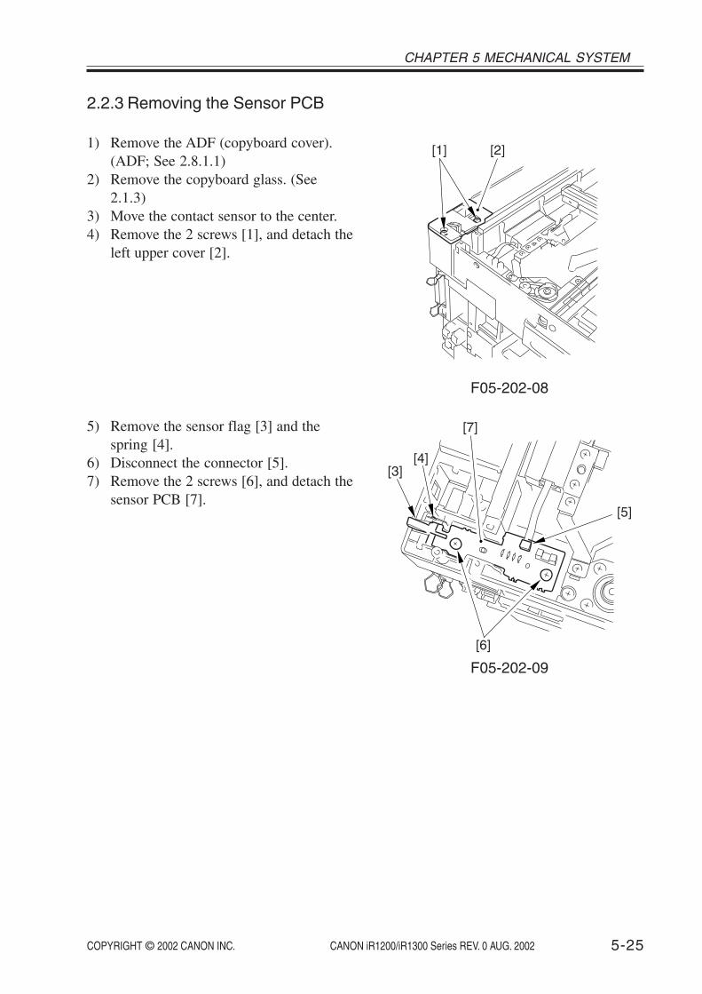
COPYRIGHT © 2002 CANON INC. 2000 2000 2000 2000 CANON iR1200/iR1300 Series REV. 0 AUG. 2002 5-25
CHAPTER 5 MECHANICAL SYSTEM
2.2.3 Removing the Sensor PCB
1) Remove the ADF (copyboard cover).(ADF; See 2.8.1.1)
2) Remove the copyboard glass. (See2.1.3)
3) Move the contact sensor to the center.4) Remove the 2 screws [1], and detach the
left upper cover [2].
[2][1]
F05-202-08
5) Remove the sensor flag [3] and thespring [4].
6) Disconnect the connector [5].7) Remove the 2 screws [6], and detach the
sensor PCB [7].
[7]
[5]
[4][3]
[6]
F05-202-09
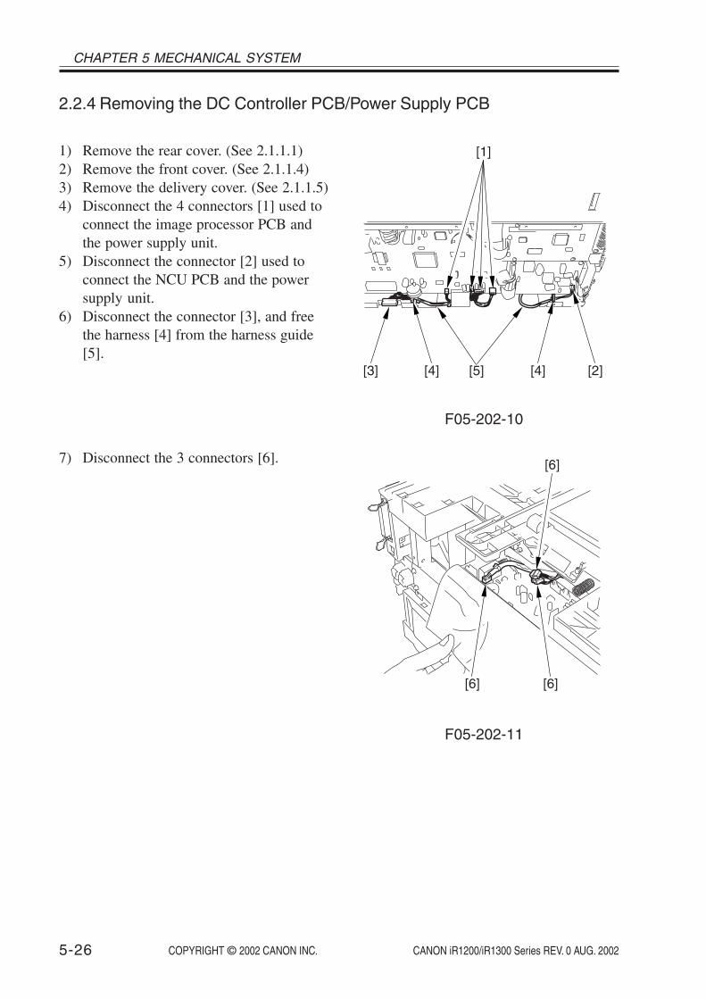
COPYRIGHT © 2002 CANON INC. 2000 2000 2000 2000 CANON iR1200/iR1300 Series REV. 0 AUG. 2002
CHAPTER 5 MECHANICAL SYSTEM
5-26
2.2.4 Removing the DC Controller PCB/Power Supply PCB
[1]
[2][4][4] [5][3]
F05-202-10
1) Remove the rear cover. (See 2.1.1.1)2) Remove the front cover. (See 2.1.1.4)3) Remove the delivery cover. (See 2.1.1.5)4) Disconnect the 4 connectors [1] used to
connect the image processor PCB andthe power supply unit.
5) Disconnect the connector [2] used toconnect the NCU PCB and the powersupply unit.
6) Disconnect the connector [3], and freethe harness [4] from the harness guide[5].
7) Disconnect the 3 connectors [6]. [6]
[6][6]
F05-202-11

COPYRIGHT © 2002 CANON INC. 2000 2000 2000 2000 CANON iR1200/iR1300 Series REV. 0 AUG. 2002 5-27
CHAPTER 5 MECHANICAL SYSTEM
8) Disconnect the connector [7].
For installation, fix the flex-ible cable tightly using adouble-sided tape.
[7]
F05-202-12
9) Remove the copyboard cover. (If themachine has the ADF, the ADF need notbe removed.)
10) Remove the cassette.11) Place the machine so that its pickup side
is at the bottom.
F05-202-13

COPYRIGHT © 2002 CANON INC. 2000 2000 2000 2000 CANON iR1200/iR1300 Series REV. 0 AUG. 2002
CHAPTER 5 MECHANICAL SYSTEM
5-28
12) Remove the 8 screws [8], and detach thebottom plate [9].
[9]
[8]
[8]
F05-202-14
13) Remove the 2 screws [10], and detachthe cassette rear cover [11].
[11]
[10]
[10]
F05-202-15

COPYRIGHT © 2002 CANON INC. 2000 2000 2000 2000 CANON iR1200/iR1300 Series REV. 0 AUG. 2002 5-29
CHAPTER 5 MECHANICAL SYSTEM
14) Free the harness [12] from the harnessguide [13].
15) Remove the 7 screws [14].16) Remove the power supply unit [15] by
moving, with your finger, the hook ofthe guide used to route the flexible cablebetween the sensor relay PCB and theDC controller PCB.
[14]
[15][14] [13][13]
[12]
[13]
[12]
[13]
[14]
[14]
F05-202-16
17) Disconnect the 3 connectors [16].18) Remove the 4 screws [17], and detach
the DC controller PCB [18].19) Remove the 5 screws [19], and detach
the power supply PCB [20].
[19][20]
[19]
[17]
[16]
[17]
[19]
[18]
F05-202-17

COPYRIGHT © 2002 CANON INC. 2000 2000 2000 2000 CANON iR1200/iR1300 Series REV. 0 AUG. 2002
CHAPTER 5 MECHANICAL SYSTEM
5-30
When mounting the powersupply unit, be sure not toleave out the sensor flag[21] of the LGL paper sen-sor from the rear of the sen-sor plate [22].
[21]
[22]
F05-202-18
2.2.5 Removing the Printer Controller PCB
1) Remove the rear cover. (See 2.1.1.1)2) Disconnect the connector [1].3) Remove the 5 screws [2], and detach the
printer controller PCB [3].
[3]
[2]
[2][1]
F05-202-19

COPYRIGHT © 2002 CANON INC. 2000 2000 2000 2000 CANON iR1200/iR1300 Series REV. 0 AUG. 2002 5-31
CHAPTER 5 MECHANICAL SYSTEM
2.2.7 Removing the Modular Jack PCB
2.2.6 Removing the NCU PCB (if equipped with fax functions)
1) Remove the rear cover. (See 2.1.1.1)2) Disconnect all connectors form the
NCU PCB.3) Remove the 4 screws [2], and detach the
NCU PCB [1].
[2]
[1]
[2]
F05-202-20
1) Remove the rear cover. (See 2.1.1.1)2) Disconnect the connector [1].3) Remove the screw [2], and detach the
modular jack PCB [3]. [3]
[1]
[2]
F05-202-212.2.8 Removing the Sensor Relay PCB
1) Remove the front cover. (See 2.1.1.4)2) Remove the 3 connectors [1].
Remove the sensor relay PCB [2].
[1]
[2]F05-202-22

COPYRIGHT © 2002 CANON INC. 2000 2000 2000 2000 CANON iR1200/iR1300 Series REV. 0 AUG. 2002
CHAPTER 5 MECHANICAL SYSTEM
5-32
2.3 Original Reading/Processing System
2.3.1 Removing the Contact Sensor
1) Remove the copyboard glass. (See2.1.3)
2) Remove the 2 spacer [1].
[1][1]
F05-203-01
3) Shift up the contact sensor [2], and dis-connect the connector [3].
4) Remove the contact sensor [2].
[2][3]
F05-203-02

COPYRIGHT © 2002 CANON INC. 2000 2000 2000 2000 CANON iR1200/iR1300 Series REV. 0 AUG. 2002 5-33
CHAPTER 5 MECHANICAL SYSTEM
2.3.2 Removing the Reader Motor Drive Unit
1) Remove the copyboard glass. (See2.1.3)
2) Free the contact sensor [1] from thedrive belt [2].
[1]
[2]
F05-203-03
3) Using a flat-blade screwdriver, removethe cover [3], and remove the screw [4].
[3]
[4]
F05-203-04

COPYRIGHT © 2002 CANON INC. 2000 2000 2000 2000 CANON iR1200/iR1300 Series REV. 0 AUG. 2002
CHAPTER 5 MECHANICAL SYSTEM
5-34
4) Slide the reader unit to the left.5) Remove the 4 screws [5], and detach the
2 grounding plates [6].6) Disconnect the connector [7].7) While paying attention to the rib [8], lift
the rear motor drive unit [9] toward theright to detach.
[5]
[5]
[6]
[5]
[7]
[6]
[9]
[8]
F05-203-05

COPYRIGHT © 2002 CANON INC. 2000 2000 2000 2000 CANON iR1200/iR1300 Series REV. 0 AUG. 2002 5-35
CHAPTER 5 MECHANICAL SYSTEM
2.3.3 Removing the Reader Unit
1) Remove the rear cover. (See 2.1.1.1)2) Remove the ADF (copyboard cover).
(ADF; See 2.8.1.1)3) Remove the retainer for the flexible
cable used to connect the analog proces-sor PCB and the image processor PCB.
4) Disconnect the 2 connectors [1], and re-move the harness retainer [2].
5) Remove the control panel. (See 2.1.2)
[2]
[1]
F05-203-06
6) Remove the 4 screws [3], and detach the2 reader stoppers [4].
[4]
[3]
F05-203-07

COPYRIGHT © 2002 CANON INC. 2000 2000 2000 2000 CANON iR1200/iR1300 Series REV. 0 AUG. 2002
CHAPTER 5 MECHANICAL SYSTEM
5-36
7) Slide the reader unit [5] as shown, anddetach the reader unit [5] from the frontside.
[5]
F05-203-08

COPYRIGHT © 2002 CANON INC. 2000 2000 2000 2000 CANON iR1200/iR1300 Series REV. 0 AUG. 2002 5-37
CHAPTER 5 MECHANICAL SYSTEM
2.4 Laser Exposure System2.4.1 Removing the Laser Scanner Unit
The laser scanner unit can-not be adjusted in the field.Do not disassemble it.
1) Remove the upper cover. (See 2.1.1.7)2) Disconnect the connector [1].
[1]
F05-204-01
3) Disconnect the 2 connectors [2].4) Remove the 2 screws [3], and detach the
plate [4].
[4][2] [3] [3]
[2]
F05-204-02

COPYRIGHT © 2002 CANON INC. 2000 2000 2000 2000 CANON iR1200/iR1300 Series REV. 0 AUG. 2002
CHAPTER 5 MECHANICAL SYSTEM
5-38
5) Remove the 4 screws [5], and detach thelaser scanner unit [6].
[6]
[5][5]
F05-204-03

COPYRIGHT © 2002 CANON INC. 2000 2000 2000 2000 CANON iR1200/iR1300 Series REV. 0 AUG. 2002 5-39
CHAPTER 5 MECHANICAL SYSTEM
2.5 Image Formation System2.5.1 Removing the Transfer Charging Roller
1) Slide the reader unit, and open the car-tridge cover.
2) Free the 2 hooks [1], and detach thetransfer charging roller [2].
[2]
[1] [1]
F05-205-01

COPYRIGHT © 2002 CANON INC. 2000 2000 2000 2000 CANON iR1200/iR1300 Series REV. 0 AUG. 2002
CHAPTER 5 MECHANICAL SYSTEM
5-40
2.5.2 Removing the Developing Cylinder/Developing Blade
1.To avoid toner scatter,spread something likenewspapers on the floorbefore work.
2. Do not touch on the sur-faces of the drum and thedeveloping cylinder.
1) Remove the cartridge from the machine.2) Attach the drum shutter stopper, and re-
move the drum unit.
As for the following, careshould be taken when at-taching or detaching thedrum unit.1. Be sure to use the drum
shutter stopper as attach-ing or detaching work.
2. Use the packaging box ofthe new drum unit ifavailable.
3. After detaching the drumunit,be sure to keep it ina protective bag to pre-vent damage to the drumsurface.
3) Detach the drum shutter stopper.4) Detach the drum shutter cover stay [1]
and remove the drum shutter cover [2].
F05-205-02
[1]
[1]
[2]

COPYRIGHT © 2002 CANON INC. 2000 2000 2000 2000 CANON iR1200/iR1300 Series REV. 0 AUG. 2002 5-41
CHAPTER 5 MECHANICAL SYSTEM
5) Remove the toner bottle from the ma-chine.
6) Remove the 6 screws [3], and removethe cover [4].
F05-205-03
[3]
[3][4]
7) Remove the 2 screws [5].8) Detach the hook [6] and remove the
cover [7].
F05-205-04
9) Remove the 3 screws [8] and remove thecovers [9].
F05-205-05
[5]
[5][7]
[6]
[9]
[8]
[8]

COPYRIGHT © 2002 CANON INC. 2000 2000 2000 2000 CANON iR1200/iR1300 Series REV. 0 AUG. 2002
CHAPTER 5 MECHANICAL SYSTEM
5-42
10) Remove the developing cylinder [10].
F05-205-06
11) Remove the 2 screws [11] and removethe developing blade [12].
F05-205-07
[10]
[11]
[12]

COPYRIGHT © 2002 CANON INC. 2000 2000 2000 2000 CANON iR1200/iR1300 Series REV. 0 AUG. 2002 5-43
CHAPTER 5 MECHANICAL SYSTEM
2.5.3 Notes on replacing the Developing Cylinder/ Developing Blade
1) Before attaching the developing cylin-der/developing blade, use flannel clothand spread toner thinly on the edge ofthe developing blade [1] facing to thedeveloping cylinder.
2) When you replace the developing blade[2], replace the developing cylinder [3]as well to avoid image blanking.
F05-205-08
Memo
When you replace the de-veloping cylinder [3], donot need to replace the de-veloping blade [2] at thesame time.
[1]
[3]
[2]

COPYRIGHT © 2002 CANON INC. 2000 2000 2000 2000 CANON iR1200/iR1300 Series REV. 0 AUG. 2002
CHAPTER 5 MECHANICAL SYSTEM
5-44
2.6 Pickup/Feeding System
2.6.1 Removing the Cassette PickupRoller
1) Remove the copyboard cover. (If themachine has the ADF, the ADF need notbe removed.)
2) Remove the cassette.3) Place the machine so that its pickup side
is at the bottom.
F05-206-01
4) Remove the 8 screws [1], and detach thebottom plate [2].
[1]
[2]
[1]
F05-206-02

COPYRIGHT © 2002 CANON INC. 2000 2000 2000 2000 CANON iR1200/iR1300 Series REV. 0 AUG. 2002 5-45
CHAPTER 5 MECHANICAL SYSTEM
5) Remove the spring [3], and detach thecassette pickup roller unit [4].
[3][4]
F05-206-03
6) Free the hook [5], and detach the cas-sette pickup roller [6].
[6]
[5]
F05-206-04

COPYRIGHT © 2002 CANON INC. 2000 2000 2000 2000 CANON iR1200/iR1300 Series REV. 0 AUG. 2002
CHAPTER 5 MECHANICAL SYSTEM
5-46
2.6.2 Removing the Cassette Pickup Solenoid
1) Remove the image processor PCB. (See2.1.1)
2) Remove the copyboard cover. (If themachine has the ADF, the ADF need notbe removed.)
3) Remove the cassette.4) Place the machine so that its pickup side
is at the bottom.
F05-206-05
5) Remove the 8 screws [1], and detach thebottom plate [2].
[1]
[2]
[1]
F05-206-06

COPYRIGHT © 2002 CANON INC. 2000 2000 2000 2000 CANON iR1200/iR1300 Series REV. 0 AUG. 2002 5-47
CHAPTER 5 MECHANICAL SYSTEM
6) Remove the 2 screws [3], and detach thecassette rear cover [4].
[4]
[3]
[3]
F05-206-07
7) Free the harness [5] from the harnessguide [6].
8) Remove the screw [7], and detach thecassette pickup solenoid [8].
[6][6]
[7]
[5] [8]
F05-206-08

COPYRIGHT © 2002 CANON INC. 2000 2000 2000 2000 CANON iR1200/iR1300 Series REV. 0 AUG. 2002
CHAPTER 5 MECHANICAL SYSTEM
5-48
2.6.3 Removing the Manual Feed Tray (upper)
1) Remove the right cover. (See 2.1.1.2)2) Remove the 4 ribs [1].3) Remove the 2 springs [2], and slide the
manual feed tray (upper) [3] to detach.
[2]
[3][1] [1]
F05-206-09
2.6.4 Removing the Manual Feed Tray (lower)
1) Remove the right cover. (See 2.1.1.2)2) Remove the 2 ribs [1], and slide the
manual feed tray (lower) [2] to detach.
[2]
[1][1]
F05-206-10

COPYRIGHT © 2002 CANON INC. 2000 2000 2000 2000 CANON iR1200/iR1300 Series REV. 0 AUG. 2002 5-49
CHAPTER 5 MECHANICAL SYSTEM
2.6.5 Removing the Manual Feed Pickup Roller
1) Remove the right cover. (See 2.1.1.2)2) Free the 2 hooks [1], and slide the 2
manual feed pickup roller retainers [2]to the left and right.
[2][1] [1]
F05-206-11
3) Free the hook [3], and slide the manualfeed pickup roller [4] to the right to de-tach.
[4] [3]
F05-206-12

COPYRIGHT © 2002 CANON INC. 2000 2000 2000 2000 CANON iR1200/iR1300 Series REV. 0 AUG. 2002
CHAPTER 5 MECHANICAL SYSTEM
5-50
2.6.6 Removing the Separation Pad
1) Remove the manual feed tray (upper).(See 2.6.3)
2) Remove the manual feed tray (lower).(See 2.6.4)
3) Open the right door.4) Remove the screw [1], and detach the
separation pad [2].
[1][2]
F05-206-13
2.6.7 Removing the Manual Feed Pickup Solenoid/Manual Feed TrayPaper Sensor
1) Remove the main motor unit. (See2.1.4)
2) Remove the screw [1], and detach themanual feed pickup solenoid [2].
3) Free the 2 hooks [3], and detach themanual feed tray paper sensor [4].
[2]
[1]
[4]
[3]
F05-206-14

COPYRIGHT © 2002 CANON INC. 2000 2000 2000 2000 CANON iR1200/iR1300 Series REV. 0 AUG. 2002 5-51
CHAPTER 5 MECHANICAL SYSTEM
2.6.8 Removing the Vertical Path Roller
1) Remove the cassette.2) Place the machine so that its pickup side
is at the bottom.
F05-206-15
3) Remove the 8 screws [1], and detach thebottom plate [2].
[1]
[2]
[1]
F05-206-16

COPYRIGHT © 2002 CANON INC. 2000 2000 2000 2000 CANON iR1200/iR1300 Series REV. 0 AUG. 2002
CHAPTER 5 MECHANICAL SYSTEM
5-52
4) Push off the claw [3] of the bushing(front) in the direction of A, and drawout the bushing (front) [4] in the direc-tion of B. [3]
[4]
B
A
F05-206-17
5) Push off the claw [5] of the bushing(rear) in the direction of A, and draw outthe bushing (rear) [6] in the direction ofB till the bushing goes out of the feederframe [7]. A [5]
B
[6]
[7]
A
F05-206-18
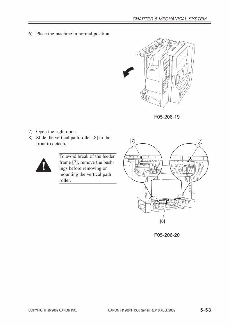
COPYRIGHT © 2002 CANON INC. 2000 2000 2000 2000 CANON iR1200/iR1300 Series REV. 0 AUG. 2002 5-53
CHAPTER 5 MECHANICAL SYSTEM
6) Place the machine in normal position.
F05-206-19
7) Open the right door.8) Slide the vertical path roller [8] to the
front to detach.
To avoid break of the feederframe [7], remove the bush-ings before removing ormounting the vertical pathroller.
[8]
[7] [7]
F05-206-20

COPYRIGHT © 2002 CANON INC. 2000 2000 2000 2000 CANON iR1200/iR1300 Series REV. 0 AUG. 2002
CHAPTER 5 MECHANICAL SYSTEM
5-54
2.6.9 Removing the Registration Roller Unit
1) Remove the image processor PCB. (See2.2.1)
2) Using long nose pliers or the like, pickthe hook [1], and detach the registrationroller gear [2].
When removing the gear,be sure to take care not tobreak the claw.
[1]
[2]
F05-206-21
3) Slide the reader unit, and open the car-tridge cover.
4) Remove the 6 screws [3], and detach theregistration roller unit [4].
[4]
[3][3]
F05-206-22
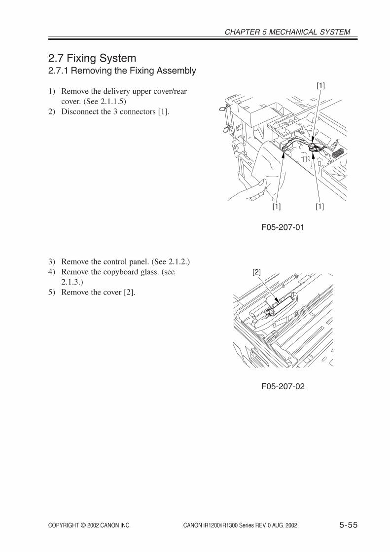
COPYRIGHT © 2002 CANON INC. 2000 2000 2000 2000 CANON iR1200/iR1300 Series REV. 0 AUG. 2002 5-55
CHAPTER 5 MECHANICAL SYSTEM
2.7 Fixing System2.7.1 Removing the Fixing Assembly
1) Remove the delivery upper cover/rearcover. (See 2.1.1.5)
2) Disconnect the 3 connectors [1].
[1]
[1][1]
F05-207-01
3) Remove the control panel. (See 2.1.2.)4) Remove the copyboard glass. (see
2.1.3.)5) Remove the cover [2].
[2]
F05-207-02
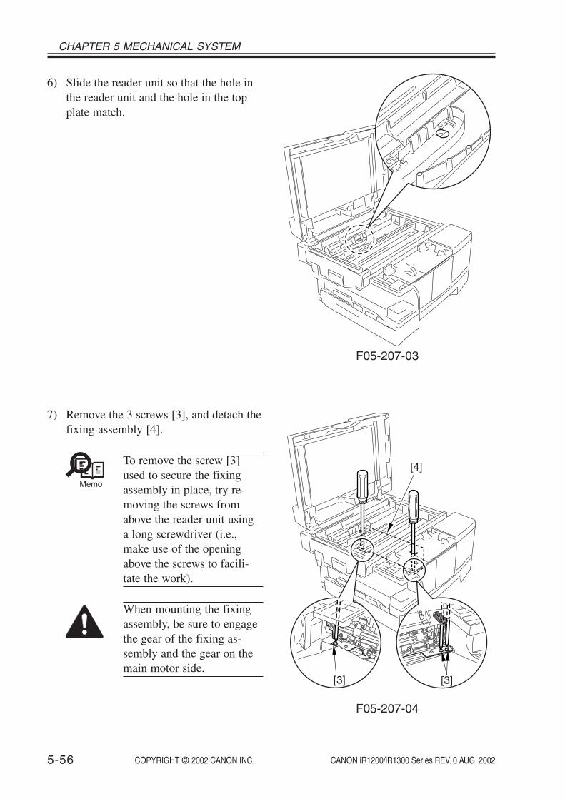
COPYRIGHT © 2002 CANON INC. 2000 2000 2000 2000 CANON iR1200/iR1300 Series REV. 0 AUG. 2002
CHAPTER 5 MECHANICAL SYSTEM
5-56
6) Slide the reader unit so that the hole inthe reader unit and the hole in the topplate match.
F05-207-03
7) Remove the 3 screws [3], and detach thefixing assembly [4].
Memo
To remove the screw [3]used to secure the fixingassembly in place, try re-moving the screws fromabove the reader unit usinga long screwdriver (i.e.,make use of the openingabove the screws to facili-tate the work).
When mounting the fixingassembly, be sure to engagethe gear of the fixing as-sembly and the gear on themain motor side.
[3]
[4]
[3]
F05-207-04

COPYRIGHT © 2002 CANON INC. 2000 2000 2000 2000 CANON iR1200/iR1300 Series REV. 0 AUG. 2002 5-57
CHAPTER 5 MECHANICAL SYSTEM
2.7.2 Removing the Fixing Film Unit/Fixing Pressure Roller
1) Remove the fixing assembly. (See 2.7.1)2) Remove the fixing upper cover [1]3) Remove the 2 screws [2].4) Remove the 2 hooks [3], and detach the
plate [4].
[2]
[4]
[3]
[3]
[1]
F05-207-05
5) Remove the 2 ribs [5], and detach thedelivery roll unit [6].
[6] [5]
[5]
F05-207-06

COPYRIGHT © 2002 CANON INC. 2000 2000 2000 2000 CANON iR1200/iR1300 Series REV. 0 AUG. 2002
CHAPTER 5 MECHANICAL SYSTEM
5-58
6) Free the harness [7] from the harnessguide [8], and detach the fixing film unit[9].
7) Remove the fixing pressure roller [10].
[9] [10]
[8][7]
[8]
F05-207-07
2.7.3 Removing the Delivery Sensor
1) Remove the fixing assembly. (See 2.7.1)2) Disconnect the connector [1].3) Free the 2 hooks [2], and detach the de-
livery sensor [3].
[1] [3]
[2]
F05-207-08

COPYRIGHT © 2002 CANON INC. 2000 2000 2000 2000 CANON iR1200/iR1300 Series REV. 0 AUG. 2002 5-59
CHAPTER 5 MECHANICAL SYSTEM
2.8 ADF System (if equipped with ADF functions)2.8.1 Externals/Auxiliary Control System2.8.1.1 Removing the ADF
[2][1]
F05-208-01
4) Remove the harness retainer [3].5) Remove the screws [4] and disconnect
the grounding wire from the core.6) Disconnect the connector [5].
[3]
[5][4]
F05-208-02
1) Remove the rear cover. (See 2.1.1.1)2) Remove the right cover. (See 2.1.1.2)3) Remove the screw [1], and detach the
ADF harness cover [2].

COPYRIGHT © 2002 CANON INC. 2000 2000 2000 2000 CANON iR1200/iR1300 Series REV. 0 AUG. 2002
CHAPTER 5 MECHANICAL SYSTEM
5-60
7) Using a flat-blade screwdriver or thelike, remove the 2 covers [6]; then, us-ing long nose pliers or the like, removethe 2 pins [7].
[6]
[7]
F05-208-03
8) Return the reader unit to its initial posi-tion.
9) Open the ADF.10) Using a flat-blade screwdriver, remove
the cover [8].11) Detach the ADF [9] from the host ma-
chine.
[9]
[8]
F05-208-04
Take care so that no partwill become trapped by har-ness of the ADF.

COPYRIGHT © 2002 CANON INC. 2000 2000 2000 2000 CANON iR1200/iR1300 Series REV. 0 AUG. 2002 5-61
CHAPTER 5 MECHANICAL SYSTEM
2.8.1.2 Removing the ADF Drive Unit
1) Remove the ADF from the host ma-chine. (See 2.8.1.1)
2) Holding the tab [1], detach the whiteplate [2].
[1][2]
F05-208-05
3) Remove the 4 screws [3], and detach theADF drive unit [4].
[4][3]
[3]
[3]
F05-208-06

COPYRIGHT © 2002 CANON INC. 2000 2000 2000 2000 CANON iR1200/iR1300 Series REV. 0 AUG. 2002
CHAPTER 5 MECHANICAL SYSTEM
5-62
2.8.1.3 Removing the ADF Motor Unit
1) Remove the white roller. (See 2.8.3.1)2) Disconnect the 3 connectors [1].3) Remove the E-ring [2] and the bushing
[3].4) Remove the 3 screws [4], and detach the
ADF motor unit [5].
The ADF motor is posi-tioned using a special tooland, therefore, cannot beadjusted in the field. Do notremove the ADF motorfrom the motor base.
[4] [3] [5][1]
[4]
[1][2]
F05-208-07

COPYRIGHT © 2002 CANON INC. 2000 2000 2000 2000 CANON iR1200/iR1300 Series REV. 0 AUG. 2002 5-63
CHAPTER 5 MECHANICAL SYSTEM
2.8.1.4 Removing the Slide Guide (front, rear)
[1]
[2]
F05-208-08
1) Open the ADF.2) Pick the tab [1], and detach the white
plate [2].
3) Remove the screw [3], slide plate [4],and gear [5]; then, detach the slide guide(front, rear) [6].
[6]
[3] [4] [5]
F05-208-09

COPYRIGHT © 2002 CANON INC. 2000 2000 2000 2000 CANON iR1200/iR1300 Series REV. 0 AUG. 2002
CHAPTER 5 MECHANICAL SYSTEM
5-64
2.8.1.5 Mounting the Slide Guide (front, rear)
1) Mount the gear [3] while trying tomatch the 2 cut-offs [1] and the marking[2] on the slide guide (front, rear).
[2]
[1]
[2]
[3]
F05-208-102) While holding down the gear to keep it
in place, mount the slide plate [4] andtighten the screw [5] to secure the platein place.
[5] [4]
F05-208-113) Adjust the left/right registration. (See
1.2.2.1 of Chapter 7.)

COPYRIGHT © 2002 CANON INC. 2000 2000 2000 2000 CANON iR1200/iR1300 Series REV. 0 AUG. 2002 5-65
CHAPTER 5 MECHANICAL SYSTEM
2.8.2 Pickup System2.8.2.1 Removing the Separation Roller Unit
[3]
[1] [2][4]
F05-208-12
1) Remove the ADF motor unit. (See2.8.1.3)
2) Remove the E-ring [1], gear [2], bush-ing[3], and pin [4].
3) Remove the spring [5], screw [6], andplate [7].
4) Remove the E-ring [8], gear [9], belt[10], and bushing [11].
[6][7][11]
[10]
[9][8]
[5]
F05-208-13

COPYRIGHT © 2002 CANON INC. 2000 2000 2000 2000 CANON iR1200/iR1300 Series REV. 0 AUG. 2002
CHAPTER 5 MECHANICAL SYSTEM
5-66
5) Remove the 2 springs [12], and slide theshaft [13] to detach the open/close coverunit [14].
[14] [13]
[12]
F05-208-14
6) Free the 3 hooks [15], and detach theseparation roller unit [16].
[16]
[15]
[15]
F05-208-15

COPYRIGHT © 2002 CANON INC. 2000 2000 2000 2000 CANON iR1200/iR1300 Series REV. 0 AUG. 2002 5-67
CHAPTER 5 MECHANICAL SYSTEM
2.8.2.2 Removing the Original Pickup roller/Original Separation roller
1) Remove the separation roller unit. (See2.8.2.1)
2) Free the 2 hooks [1], and detach theoriginal pickup roller [2].
3) Free the 2 hooks [3], and detach theoriginal separation roller [4]. [1]
[1]
[2]
[3]
[3]
[4]
F05-208-16
2.8.2.3 Removing the Original Sensor/Registration Sensor
1) Remove the ADF motor unit. (See2.8.1.3)
2) Free the 2 hooks [1], and detach theoriginal sensor [2].
3) Free the 2 hooks [3], and detach the reg-istration sensor [4].
[3][1]
[4][2]
F05-208-17

COPYRIGHT © 2002 CANON INC. 2000 2000 2000 2000 CANON iR1200/iR1300 Series REV. 0 AUG. 2002
CHAPTER 5 MECHANICAL SYSTEM
5-68
2.8.2.4 Removing the Original Separation Pad
1) Open the ADF.2) Hold the tab, and detach the white
plate[2].
[1]
[2]
F05-208-18
3) Remove the spring [3], and detach theoriginal separation pad [4]. [4]
[3]
F05-208-19

COPYRIGHT © 2002 CANON INC. 2000 2000 2000 2000 CANON iR1200/iR1300 Series REV. 0 AUG. 2002 5-69
CHAPTER 5 MECHANICAL SYSTEM
2.8.2.5 Removing the ADF Registration Roller
1) Remove the ADF drive unit. (See2.8.1.2)
2) Remove the E-ring [1], and bushing [2].
[1]
[2]
F05-208-20
3) Remove the spring [3] and the screw[4], and detach the plate [5]. [5]
[4]
[3]
F05-208-21

COPYRIGHT © 2002 CANON INC. 2000 2000 2000 2000 CANON iR1200/iR1300 Series REV. 0 AUG. 2002
CHAPTER 5 MECHANICAL SYSTEM
5-70
4) Remove the E-ring [6], gear [7], bush-ing [8], pin [9], and 2 belts [10].
5) Remove the ADF registration roller[11].
[10] [9]
[11]
[7]
[8]
[6]
F05-208-22

COPYRIGHT © 2002 CANON INC. 2000 2000 2000 2000 CANON iR1200/iR1300 Series REV. 0 AUG. 2002 5-71
CHAPTER 5 MECHANICAL SYSTEM
2.8.3 Feeding System2.8.3.1 Removing the White Roller
1) Remove the ADF drive unit. (See2.8.1.2)
2) Remove the spring [1] and the hook [2].
[1]
[2]
F05-208-23
3) Remove the spring [3] and the hook [4],and detach the white roller [5].
[4] [3]
[5]
F05-208-24

COPYRIGHT © 2002 CANON INC. 2000 2000 2000 2000 CANON iR1200/iR1300 Series REV. 0 AUG. 2002
CHAPTER 5 MECHANICAL SYSTEM
5-72
2.8.3.2 Removing the Feeding Outside Guide
1) Remove the ADF drive unit. (See2.8.1.2)
2) Disconnect the connector [1], and de-tach the grounding plate [2].
3) Remove the static eliminator [3] asmuch as shown.
[2] [3][1]
[3]
F05-208-25
4) Remove the 2 screws [4], and detach thefeeding outside guide [5].
[5]
[4]
F05-208-26

COPYRIGHT © 2002 CANON INC. 2000 2000 2000 2000 CANON iR1200/iR1300 Series REV. 0 AUG. 2002 5-73
CHAPTER 5 MECHANICAL SYSTEM
2.8.3.3 Removing the Feed Roll
1) Remove the feeding outside guide. (See2.8.3.2)
2) Free the 2 hooks [1], and detach thefeed roll [2]. [1]
[1]
[2]
F05-208-27

COPYRIGHT © 2002 CANON INC. 2000 2000 2000 2000 CANON iR1200/iR1300 Series REV. 0 AUG. 2002
CHAPTER 5 MECHANICAL SYSTEM
5-74
2.8.3.4 Removing the Original Feed Roller
1) Remove the delivery stacking tray. (See2.8.4.1)
2) Remove the 2 E-rings [1].
[1]
[1]
F05-208-28
3) Slide the original feed roller [2] to theleft, and remove the pin [3], gear [4],and bushing [5]; then, detach the origi-nal feed roller [2].
[2]
[3] [5][4]
F05-208-29

COPYRIGHT © 2002 CANON INC. 2000 2000 2000 2000 CANON iR1200/iR1300 Series REV. 0 AUG. 2002 5-75
CHAPTER 5 MECHANICAL SYSTEM
2.8.4 Delivery System2.8.4.1 Removing the Delivery Stacking Tray/Original Delivery Roller
1) Remove the feeding outside guide. (See2.8.3.2)
2) Remove the E-ring [1], gear [2], pin [3],and bushing [4]. [2]
[4]
[3]
[1]
F05-208-30
3) Remove the 2 screws [5], and free the 2hooks [6].
4) Remove the delivery stacking tray [7],and detach the original delivery roller[8].
[5]
[6][6]
[8][7]
F05-208-31
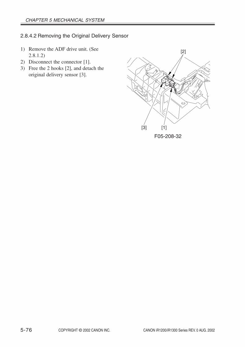
COPYRIGHT © 2002 CANON INC. 2000 2000 2000 2000 CANON iR1200/iR1300 Series REV. 0 AUG. 2002
CHAPTER 5 MECHANICAL SYSTEM
5-76
2.8.4.2 Removing the Original Delivery Sensor
1) Remove the ADF drive unit. (See2.8.1.2)
2) Disconnect the connector [1].3) Free the 2 hooks [2], and detach the
original delivery sensor [3].
[2]
[1][3]
F05-208-32

COPYRIGHT © 2002 CANON INC. 2000 2000 2000 2000 CANON iR1200/iR1300 Series REV. 0 AUG. 2002
CHAPTER 6
MAINTENANCE AND INSPECTION


COPYRIGHT © 2002 CANON INC. 2000 2000 2000 2000 CANON iR1200/iR1300 Series REV. 0 AUG. 2002 6-1
CHAPTER 6 MAINTENANCE AND INSPECTION
1 Periodically Replaced Parts
The machine does not have parts that require periodical replacement.
2 Durables
The machine does not have durables that require replacement once or more during the lifeof the product because of wear or damage.
3 Scheduled Servicing Chart
The machine does not have items (parts or durables) that require scheduled servicing. Tohelp prolong the life of the product and its parts, it is recommended that the following beperformed at time of a service visit.
As of August 2002Work Procedure1. Question key person in charge, and obtain a general idea of the issue.2. Make repairs of any faults.3. Make test copies, and check the output for the following:
(1) image density against standards, (2) soiling of the background,(3) clarity of characters, (4) margin, (5) fixing, faulty registration, soiling of the back of the page.
Standards for Margin (single-sided)Leading edge: 3.0 ± 2.0 mm (0.12” ± 0.08”)Left/right edge: 2.5 ± 2.0 mm (0.10” ± 0.08”)
4. Clean the parts: As needed, remove the cartridge before starting the work. (See 4.2 ofChapter 6)
5. Make test copies.6. Clean up the area around the machine.

COPYRIGHT © 2002 CANON INC. 2000 2000 2000 2000 CANON iR1200/iR1300 Series REV. 0 AUG. 2002
CHAPTER 6 MAINTENANCE AND INSPECTION
6-2
4 Cleaning
4.1 Cleaning by the User (machine)The user is expected to perform the following so that the machine may be used in its best
condition at all times.
4.1.1 Cleaning the Fixing Pressure RollerIf the faces or the backs of printed sheets show soiling in the form of black dots, clean the
fixing pressure roller as follows:
1) Place an A4 or larger sheet of plain paper in the manual feed tray.2) Press the Additional Functions key, and hold down the Right Arrow key or the Left Ar-
row key until the LCD indicates ‘6. ADJUST/CLEAN’.3) Press the OK key.4) Check to make sure that the LCD indicates ‘1. ROLLER CLEANING’, and press the
OK key. In response, the machine will start cleaning the fixing pressure roller.
Memo
It takes about 3 min before the paper is delivered to the delivery tray afterthe cleaning of the fixing pressure roller is started.
4.1.2 Other CleaningIf images tend to be soiled, advise the user to clean the following as needed.
T06-401-01
No.
1
2
3
4
Part
Copyboard glass
Copyboard glass retainer
Vertical size plate
White plate
Instructions
Wipe it with a cloth moistened with water (and wrung well);then, dry wipe it.Wipe it with a cloth moistened with water (and wrung well);then, dry wipe it.Wipe it with a cloth moistened with water (and wrung well);then, dry wipe it.Wipe it with a cloth moistened with water (and wrung well);then, dry wipe it.

COPYRIGHT © 2002 CANON INC. 2000 2000 2000 2000 CANON iR1200/iR1300 Series REV. 0 AUG. 2002 6-3
CHAPTER 6 MAINTENANCE AND INSPECTION
4.2 Cleaning by the User (ADF)4.2.1 Cleaning the White Roller
If the backs of originals tend to become soiled, clean the white roller as follows:
1) Open the ADF, and clean the bottom of the white roller with a cloth moistened with wa-ter (and wrung well). If the dirt is excessive, use alcohol with lint-free paper. Be sure todry wipe it with a cloth or lint-free paper thereafter.
2) Press the Additional Functions key, and hold down the Right Arrow or Left Arrow keyuntil the LCD indicates ‘6. ADJUST/CLEAN’.
3) Press the OK key.4) Hold down the Right Arrow key or the Left Arrow key until the LCD indicates ‘2.
CLEAN ADF ROLLER’.5) Press the OK key.6) When the LCD indicates ‘START CLEAN : [SET]’, press the OK key. In response, the
white roller makes a 120° turn.7) Wipe the bottom of the white roller with a cloth moistened with water (and wrung well);
then, dry wipe it.8) Repeat steps 6) and 7) to clean the entire surface of the white roller.9) Press the Stop key to end.
4.2.2 Other CleaningIf images tend to become soiled, advise the user to clean the following as needed.
No.
1
Part
White plate
Instructions
Wipe it with a cloth moistened with water (and wrung well);then, dry wipe it.
T06-402-01

COPYRIGHT © 2002 CANON INC. 2000 2000 2000 2000 CANON iR1200/iR1300 Series REV. 0 AUG. 2002
CHAPTER 6 MAINTENANCE AND INSPECTION
6-4
4.3 Cleaning at Time of a Service Visit (machine)At time of a service visit, clean the items described in 4.1 “Cleaning by the User (ma-
chine)”; then, perform the following as needed:
Do not clean the photosensitive drum.
4.3.1 Selfoc Lens Array of the Contact Sensor
1. If the face of the light guide assembly becomes soiled or scratched, itsoptical characteristics will be affected. Do not touch the light guide as-sembly.
2. The contact sensor is vulnerable to static charges. Be sure to providemeasures against static damage before touching it.
3. Be sure to fit back the spacer after the cleaning work; otherwise, thecontact sensor may not work properly.
Lightly remove any dirt with a dry, soft cloth.
Selfoc lens array(black)
Light guideassembly(translucent)
Spacer
Spacer
F06-403-01

COPYRIGHT © 2002 CANON INC. 2000 2000 2000 2000 CANON iR1200/iR1300 Series REV. 0 AUG. 2002 6-5
CHAPTER 6 MAINTENANCE AND INSPECTION
4.3.2 Cassette Pickup RollerClean it with a cloth moistened with water (and wrung well). If the dirt is excessive, use
alcohol with lint-free paper thereafter, be sure to dry wipe it with a cloth or lint-free paper.
4.3.3 Manual Feed Pickup RollerDry wipe it with a cloth moistened with water (and wrung well). If the dirt is excessive,
use alcohol with lint-free paper thereafter, be sure to dry wipe it with a cloth or lint-free pa-per.
4.3.4 Separation PadDry wipe it with lint-free paper.
4.3.5 Registration RollerClean it with a cloth moistened with water (and wrung well). If the dirt is excessive, use
alcohol with lint-free paper thereafter, use a cloth or lint-free paper.
4.3.6 Transfer GuideClean it with a cloth moistened with water (and wrung well) thereafter, dry wipe it with a
cloth or lint-free paper.
4.3.7 Transfer Charging RollerAs a rule, do not touch or clean it. However, if cleaning proves necessary as when the
cause of an image fault is the transfer roller, clean it while taking care not to handle theroller or not to subject it to solvent or oils.
Use lint-free paper and dry wipe it. Do not use water or solvent. During cleaning, takecare not to impose force on the rubber area of the transfer charging roller.
4.3.8 Separation Static EliminatorClean it with a blower brush.
4.3.9 Paper PathDry wipe it with lint-free paper.
4.3.10 Fixing Inlet GuideUse alcohol with a soft cloth.
4.3.11 Fixing Pressure RollerIf dirt cannot be removed by executing fixing pressure roller cleaning from the Additional
Functions menu, use alcohol and a soft cloth.
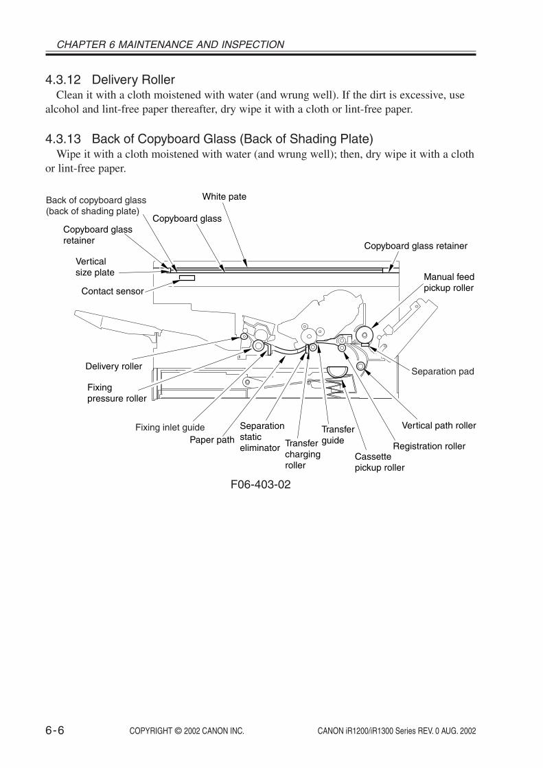
COPYRIGHT © 2002 CANON INC. 2000 2000 2000 2000 CANON iR1200/iR1300 Series REV. 0 AUG. 2002
CHAPTER 6 MAINTENANCE AND INSPECTION
6-6
4.3.12 Delivery RollerClean it with a cloth moistened with water (and wrung well). If the dirt is excessive, use
alcohol and lint-free paper thereafter, dry wipe it with a cloth or lint-free paper.
4.3.13 Back of Copyboard Glass (Back of Shading Plate)Wipe it with a cloth moistened with water (and wrung well); then, dry wipe it with a cloth
or lint-free paper.
Contact sensor
Verticalsize plate
Copyboard glass
White pate
Separation pad
Manual feed pickup roller
Copyboard glass retainer
Back of copyboard glass(back of shading plate)
Copyboard glassretainer
Delivery roller
Fixing pressure roller
Cassettepickup roller
Vertical path roller
Registration rollerTransferchargingroller
Paper pathTransferguide
Separationstaticeliminator
Fixing inlet guide
F06-403-02

COPYRIGHT © 2002 CANON INC. 2000 2000 2000 2000 CANON iR1200/iR1300 Series REV. 0 AUG. 2002 6-7
CHAPTER 6 MAINTENANCE AND INSPECTION
4.4 Cleaning at Time of a Service Visit (ADF)At time of a service visit, clean the items described in 4.2 “Cleaning by the User (ADF)”;
then, perform the following as needed:
4.4.1 Original Pickup RollerClean it with a cloth moistened with water (and wrung well). If dirt is excessive, use alco-
hol with lint-free paper thereafter, dry wipe it with a cloth or lint-free paper.
4.4.2 Original Separation RollerClean it with a cloth moistened with water (and wrung well). if the dirt is excessive, use
alcohol with lint-free paper thereafter, dry wipe it with a cloth or lint-free paper.
4.4.3 Original Separation PadClean it with a cloth moistened with water (and wrung well). If the dirt is excessive, use
alcohol and lint-free paper thereafter, dry wipe it with a cloth or lint-free paper.
4.4.4 ADF Registration RollerClean it with a cloth moistened with water (and wrung well). If the dirt is excessive, use
alcohol and lint-free paper thereafter, dry wipe it with a cloth or lint-free paper.
4.4.5 Original Feed RollerClean it with a cloth moistened with water (and wrung well). If the dirt is excessive, use
alcohol and lint-free paper thereafter, dry wipe it with a cloth or lint-free paper.
4.4.6 Original Delivery RollerClean it with a cloth moistened with water (and wrung well). If the dirt is excessive, use
alcohol and lint-free paper thereafter, dry wipe it with a cloth or lint-free paper.

COPYRIGHT © 2002 CANON INC. 2000 2000 2000 2000 CANON iR1200/iR1300 Series REV. 0 AUG. 2002
CHAPTER 6 MAINTENANCE AND INSPECTION
6-8
4.4.7 Copyboard Glass (Original Reading Area)Wipe it with a cloth moistened with water (and wrung well); then, dry wipe it with a cloth
or lint-free paper.
Original pickup roller
Original separation roller Originaldelivery roller
Originalfeed roller
White roller
ADF registration roller
Originalseparation padWhite pate Copyboard glass
(original reading area)
F06-404-01

COPYRIGHT © 2002 CANON INC. 2000 2000 2000 2000 CANON iR1200/iR1300 Series REV. 0 AUG. 2002
CHAPTER 7
TROUBLESHOOTING

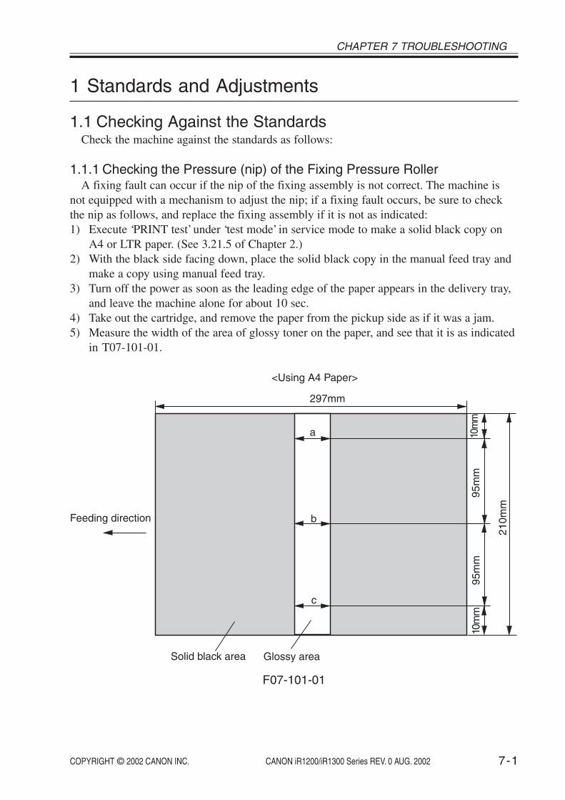
COPYRIGHT © 2002 CANON INC. 2000 2000 2000 2000 CANON iR1200/iR1300 Series REV. 0 AUG. 2002 7-1
CHAPTER 7 TROUBLESHOOTING
1 Standards and Adjustments
1.1 Checking Against the StandardsCheck the machine against the standards as follows:
1.1.1 Checking the Pressure (nip) of the Fixing Pressure RollerA fixing fault can occur if the nip of the fixing assembly is not correct. The machine is
not equipped with a mechanism to adjust the nip; if a fixing fault occurs, be sure to checkthe nip as follows, and replace the fixing assembly if it is not as indicated:1) Execute ‘PRINT test’ under ‘test mode’ in service mode to make a solid black copy on
A4 or LTR paper. (See 3.21.5 of Chapter 2.)2) With the black side facing down, place the solid black copy in the manual feed tray and
make a copy using manual feed tray.3) Turn off the power as soon as the leading edge of the paper appears in the delivery tray,
and leave the machine alone for about 10 sec.4) Take out the cartridge, and remove the paper from the pickup side as if it was a jam.5) Measure the width of the area of glossy toner on the paper, and see that it is as indicated
in T07-101-01.
Feeding direction
Glossy area
10m
m95
mm
95m
m
Solid black area
a
b
c
10m
m
210m
m
297mm
<Using A4 Paper>
F07-101-01

COPYRIGHT © 2002 CANON INC. 2000 2000 2000 2000 CANON iR1200/iR1300 Series REV. 0 AUG. 2002
CHAPTER 7 TROUBLESHOOTING
7-2
Feeding direction
Glossy area
10m
m98
mm
98m
m
Solid black area
a
b
c
10m
m
216m
m
279mm
<Using LTR Paper>
F07-101-02
Dimension
5.5±0.5 mm
0.5 mm or less
0.5 mm or less
0.5 mm or less
a
|b-a|
|b-c|
|c-a|
T07-101-01

COPYRIGHT © 2002 CANON INC. 2000 2000 2000 2000 CANON iR1200/iR1300 Series REV. 0 AUG. 2002 7-3
CHAPTER 7 TROUBLESHOOTING
1.2 Making Adjustments1.2.1 Making Adjustments When Replacing Major Parts
You need to make the following adjustments whenever you have replaced the machine’smajor parts.
Be sure to make the appropriate adjustments if you have replaced a specificmajor part.
Part replaced
Image processor PCBContact sensor
Item of adjustment
all adjustments, including ADF adjustmentcontact sensor LED intensity auto adjustment
To replace the image processor PCB, be sure to work according to the in-structions given for the replacement of the image processor PCB (See 1.4.1of Chapter 7).

COPYRIGHT © 2002 CANON INC. 2000 2000 2000 2000 CANON iR1200/iR1300 Series REV. 0 AUG. 2002
CHAPTER 7 TROUBLESHOOTING
7-4
1.2.2 Preparing a Test Sheet for AdjustmentYou will need to prepare a test sheet as follows for adjustments (except contact sensor
LED intensity auto adjustment); refer to F07-102-01 and F07-102-02 for the specifics:
Preparing a Test Sheet: On a sheet of A4 or LTR paper, draw straight lines as indicated:
10m
m
10mm
10mm
10mm
<Using A4 Paper>
Draw straight lines.
(feeding direction)
10mm
297mm
210m
m
F07-102-0110
mm
10mm
10mm
10mm
<Using LTR Paper>
Draw straight lines.
(feeding direction)
10mm
279mm
216m
m
F07-102-02

COPYRIGHT © 2002 CANON INC. 2000 2000 2000 2000 CANON iR1200/iR1300 Series REV. 0 AUG. 2002 7-5
CHAPTER 7 TROUBLESHOOTING
1.2.3 Adjusting the Mechanical SystemsThe machine’s mechanical systems do not require adjustments.
1.2.4 Adjusting the Electrical Systems1.2.4.1 Contact Sensor LED Intensity Auto Adjustment
Before starting adjustment, verify that there is nothing on the copyboardglass. Also verify that the ADF (copyboard cover) is securely closed.
Execute auto adjustment of the contact sensor LED intensity as follows:1) Press the Additional Functions key and the # key to start service mode.2) Press the Left/Right Arrow key so that ‘TEST MODE’ is indicated.3) Press the OK key.4) Press ‘2’ on the keypad so that ‘TEST MODE’ is indicated.5) Press ‘7’ on the keypad to clear the CCD parameter.6) Press the Stop key to return to ‘TEST MODE’.7) Press ‘2’ on the keypad so that ‘2: CCD TEST’ is indicated.8) Press ‘8’ on the keypad so that the machine starts contact sensor LED intensity auto ad-
justment.9) End the work when the LCD indicates ‘OK’; if it indicates ‘NG’, on the other hand,
start over.10) Press the Stop key and the Additional Functions key (to end TEST MODE).

COPYRIGHT © 2002 CANON INC. 2000 2000 2000 2000 CANON iR1200/iR1300 Series REV. 0 AUG. 2002
CHAPTER 7 TROUBLESHOOTING
7-6
1.2.4.2 Leading Edge Read Start Position AdjustmentAdjust the leading edge read start position for book mode as follows:
1) Make a copy of the test sheet in book mode on paper of the same size in Direct. (See1.2.2 of Chapter 7.)
2) Measure the length of L on the copy (i.e., the length obtained by subtracting the leadingedge margin from the line found 10 mm from the leading edge; it must be 7 ± 0.5 mm).
Copy of the test sheet
(feeding direction)
Leading edge margin
L
F07-102-03
3) Press the Additional Functions key and the # key to start service mode.4) Press the left/Right Arrow key so that ‘#6 SCANNER’ is indicated.5) Press the OK key.6) Press the Left/Right Arrow key so that ‘7: CCD’ is indicated.7) Press the OK key.8) Press the Left/Right Arrow key so that the 2nd row of the LCD indicates ‘023:’.9) Enter an appropriate correction value using the Left/Right Arrow key so that the length
of L measured in step 2 is 7 mm. (An increase by ‘1’ will decrease the length of L byabout 0.1 mm.)
10) Press the OK key.11) Press the Stop key (to end SCANNER).12) Make a copy of the test sheet in book mode on paper of the same size in Direct; then,
check to make sure that the length of L is as indicated.13) End the work if the length of L is as indicated; otherwise, start over with step 2).

COPYRIGHT © 2002 CANON INC. 2000 2000 2000 2000 CANON iR1200/iR1300 Series REV. 0 AUG. 2002 7-7
CHAPTER 7 TROUBLESHOOTING
1.2.4.3 Left/Right Edge Read Start Position AdjustmentAdjust the left/right edge read start position for book mode as follows:
1) If LTR paper is available, prepare a test sheet using LTR paper. (See 1.2.2 of Chapter 7.)If no LTR paper is available, cut a larger sheet of paper so that its width is 216 mm;then, prepare a test sheet as instructed in 1.2.2, making sure that the width is 216 mm; asfor its length, make sure that it fits the copyboard glass.
2) Make a copy of the sheet in book mode on paper of the same size to a reduction ratio of80%.
3) Measure the length of b-a of the copy, and check to make sure that it is as indicated. (Itmust be 0 ± 0.4 mm.)
Copy of the test sheet
(feeding direction)
a
b
F07-102-04
4) Press the Additional Functions key and the # key to start service mode.5) Press the Left/Right Arrow key so that ‘#6 SCANNER’ is indicated.6) Press the OK key.7) Press the Left/Right Arrow key so that ‘7: CCD’ is indicated.8) Press the OK key.9) Press the Left/Right Arrow key so that the 2nd row of the LCD indicates ‘021:’.10) Enter an appropriate correction value on the keypad so that the length of b-a measured
in step 2) is as indicated. (An increase by ‘1’ will decrease the length of b by about 0.03mm while increasing the length of a by about 0.03 mm.)
11) Press the OK key.12) Press the Stop key (to end SCANNER).13) Make a copy of the test sheet in book mode on paper of the same size; then, check to
make sure that the length of L on the copy is as indicated.14) End the work if the length of L is as indicated; otherwise, start over with step 2).

COPYRIGHT © 2002 CANON INC. 2000 2000 2000 2000 CANON iR1200/iR1300 Series REV. 0 AUG. 2002
CHAPTER 7 TROUBLESHOOTING
7-8
1.3 Making Adjustments (ADF)1.3.1 Items of Adjustment and Sequence of Work
The ADF must be adjusted for the following items and in the following sequence of work:
1. If you have replaced major parts of the ADF, you must always executethe following: registration arch auto adjustment, original read positionadjustment. Then, check to make sure that the settings of other items ofadjustment are as indicated; if not, make adjustments starting with thepreceding item of adjustment.
2. Each item of adjustment affects the subsequent items of adjustment. Ifyou have made adjustments, therefore, be sure to check that the settingof the item of adjustment that follows is also as indicated; if not, be sureto start over with the preceding item.
1.3.2 Preparing a Test Sheet for AdjustmentWhen making adjustments (except registration arch auto adjustment and original read po-
sition adjustment) for the ADF, you will need a test sheet like the one used for the copier.Prepare a test sheet by referring to the instructions given under 1.2.2 of Chapter 7.
Sequence
1234567
Item of adjustment
registration arch auto adjustmentskew removaloriginal read position adjustmentoriginal feed speed adjustmentleading edge read start position adjustmenttrailing edge read end position adjustmentleft/right registration adjustment

COPYRIGHT © 2002 CANON INC. 2000 2000 2000 2000 CANON iR1200/iR1300 Series REV. 0 AUG. 2002 7-9
CHAPTER 7 TROUBLESHOOTING
1.3.3 Adjusting the Mechanical Systems1.3.3.1 Removing the Skew
Make a copy of the test sheet using the ADF in Direct, and make sure that the skew is asindicated (T07-103-01). (See 1.2.2 of Chapter 7.)
Copy of the test sheet
a
b
(feeding direction)
F07-103-01
T07-103-01
1) Open the ADF.2) Loosen the 3 screws [1], and move the left hinge up and down so that the skew will be
as indicated by referring to the index graduated at 1-mm intervals.
[1]
F07-103-02
b-a
Dimension (using A4)
0 ± 1.3 mm
Dimension (using LTR)
0 ± 1.3 mm
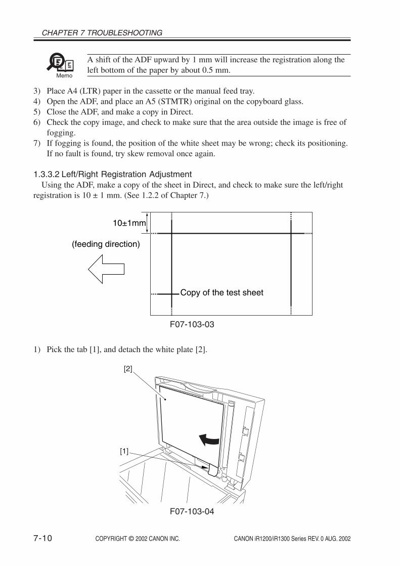
COPYRIGHT © 2002 CANON INC. 2000 2000 2000 2000 CANON iR1200/iR1300 Series REV. 0 AUG. 2002
CHAPTER 7 TROUBLESHOOTING
7-10
Memo
A shift of the ADF upward by 1 mm will increase the registration along theleft bottom of the paper by about 0.5 mm.
3) Place A4 (LTR) paper in the cassette or the manual feed tray.4) Open the ADF, and place an A5 (STMTR) original on the copyboard glass.5) Close the ADF, and make a copy in Direct.6) Check the copy image, and check to make sure that the area outside the image is free of
fogging.7) If fogging is found, the position of the white sheet may be wrong; check its positioning.
If no fault is found, try skew removal once again.
1.3.3.2 Left/Right Registration AdjustmentUsing the ADF, make a copy of the sheet in Direct, and check to make sure the left/right
registration is 10 ± 1 mm. (See 1.2.2 of Chapter 7.)
Copy of the test sheet
(feeding direction)
10±1mm
F07-103-03
1) Pick the tab [1], and detach the white plate [2].
[1]
[2]
F07-103-04

COPYRIGHT © 2002 CANON INC. 2000 2000 2000 2000 CANON iR1200/iR1300 Series REV. 0 AUG. 2002 7-11
CHAPTER 7 TROUBLESHOOTING
2) Loosen the screw [3], and move the slide guide to the front/rear with reference to the in-dex graduated at 1-mm intervals until the registration is as indicated.
[3]
F07-103-05
Memo
A shift of the slide guide up by 1 mm will increase the registration on theright (top of paper) by 1 mm.
Do not remove the screw [3]; otherwise, you must work as instructed formounting of the slide guide. (See 2.8.1.5 of Chapter 5)

COPYRIGHT © 2002 CANON INC. 2000 2000 2000 2000 CANON iR1200/iR1300 Series REV. 0 AUG. 2002
CHAPTER 7 TROUBLESHOOTING
7-12
1.3.4 Adjusting the Electrical Systems1.3.4.1 Registration Arch Auto Adjustment
Adjust the registration arch for the ADF registration roller as follows:1) Press the Additional Functions key and the # key to start service mode.2) Press the Left/Right Arrow key so that ‘TEST MODE’ is indicated.3) Press ‘6’ on the keypad so that ‘FACULTY TEST’ is indicated.4) Press ‘4’ on the keypad so that ‘6-4 ADF’ is indicated.5) Place 10 sheets of A4 paper in the ADF.6) Press ‘8’ on the keypad so that the machine will start registration arch auto adjustment.7) End the work when the LCD indicates ‘OK’; if it indicates ‘NG’, on the other hand,
start over the adjustment.8) Press the Stop key and then the Additional Functions key (to end TEST MODE).
1.3.4.2 Original Read Position AdjustmentAdjust the contact sensor original read position for ADF mode as follows:
Check to make sure that the ADF is fully closed before starting the work.Moreover, check to be sure of the absence of any object on the copyboardglass.
1) Press the Additional Functions key and the # key to start service mode.2) Press the Left/Right Arrow key so that ‘TEST MODE’ is indicated.3) Press the OK key.4) Press ‘2’ on the keypad so that ‘2: CCD TEST’ is indicated.5) Press ‘3’ so that the machine starts original read position adjustment.6) End the work when the LCD indicates ‘OK’; if it indicates ‘NG’, on the other hand,
start over the adjustment.7) Press the Stop key and the Additional Functions key (to end TEST MODE).

COPYRIGHT © 2002 CANON INC. 2000 2000 2000 2000 CANON iR1200/iR1300 Series REV. 0 AUG. 2002 7-13
CHAPTER 7 TROUBLESHOOTING
1.3.4.3 Original Speed AdjustmentAdjust the speed at which originals are moved for ADF mode as follows:
1) Make a copy of the test sheet in ADF mode on paper of the same size in Direct. (See1.2.2 of Chapter 7.)
2) Measure the length “L” in the middle of the copy output. (It must be 277 ± 1 mm forA4, 259 ± 1 mm for LTR.)
Copy of the test sheet
L(feeding direction)
F07-103-06
3) Press the Additional Functions key and the # key to start service mode.4) Press the Left/Right Arrow key so that ‘#6 SCANNER’ is indicated.5) Press the OK key.6) Press the Left/Right Arrow key so that ‘7: CCD’ is indicated.7) Press the OK key.8) Press the Left/Right Arrow key so that the 2nd row of the LCD indicates ‘034:’.9) Enter a appropriate correction value using the Left/Right Arrow key so that the length of
L measured in step 2) is as indicated. (An increase by ‘1’ will increase the length of Lby about 0.5 mm.)
10) Press the OK key.11) Press the Stop key (to end SCANNER).12) Make a copy of the test sheet in ADF mode on paper of the same size in Direct; then,
check to make sure that the length of L of the copy is as indicated.13) End the work if the length of L is as indicated; otherwise, start over with step 2).

COPYRIGHT © 2002 CANON INC. 2000 2000 2000 2000 CANON iR1200/iR1300 Series REV. 0 AUG. 2002
CHAPTER 7 TROUBLESHOOTING
7-14
1.3.4.4 Leading Edge Read Start Position AdjustmentAdjust the leading edge start position for ADF mode as follows:
1) Make a copy of the test sheet in ADF mode on paper of the same size in Direct. (See1.2.2 of Chapter 7.)
2) Measure the length of L on the copy (i.e., obtained by subtracting the leading edge mar-gin from the position of the line found 10 mm from the leading edge; it must be 7 ± 0.5mm).
Copy of the test sheet
(feeding direction)
Leading edge margin
L
F07-103-07
3) Press the Additional Functions key and the # key to start service mode.4) Press the Left/Right Arrow key so that ‘#6 SCANNER’ is indicated.5) Press the OK key.6) Press the Left/Right Arrow key so that ‘7: CCD’ is indicated.7) Press the OK key.8) Press the Left/Right Arrow key so that the 2nd row of the LCD indicates ‘024’.9) Enter an appropriate correction value using the Left/Right Arrow key so that the length
of L measured in step 2) is 7 mm. (An increase of ‘1’ will increase the length of L byabout 0.1 mm.)
10) Press the OK key.11) Press the Stop key (to end SCANNER).12) Make a copy of the test sheet in ADF mode on paper of the same size in Direct; then,
check to make sure that the length of L on the copy is as indicated.13) End the work if the length of L is as indicated; otherwise, start over with step 2).

COPYRIGHT © 2002 CANON INC. 2000 2000 2000 2000 CANON iR1200/iR1300 Series REV. 0 AUG. 2002 7-15
CHAPTER 7 TROUBLESHOOTING
1.3.4.5 Trailing Edge Read End Position AdjustmentTo adjust the trailing edge margin for ADF mode, go through the following:
1) Make a copy of the test sheet prepared in 1.2.2 of Chapter 7 on LGL paper in Direct.2) Measure the length “L” on the copy output. (standard: 8 ±0.5 mm)
Copy of the test sheet
(feeding direction)
Trailing edge marginL
F07-103-08
3) Press the Additional Functions key and the # key to start service mode.4) Press the Left/Right arrow key so that ‘#6 SCANNER’ is indicated.5) Press the OK key.6) Press the Left/Right arrow key so that ‘7: CCD’ is indicated.7) Press the OK key.8) Press the Left/Right arrow keys so that the 2nd row of the LCD indicates ‘025:’.9) Enter a correction value using the Left /Right key so that the length of “L” measured in
step 2) is 8 mm (trailing edge margin of 2 mm; an increase by ‘1’ will decrease thelength of “L” by about 0.1 mm).
10) Press the OK key.11) Press the Stop key (to leave ‘SCANNER’).12) Make a copy of the Test Sheet in Direct on LGL paper and in ADF mode. Then, check
to make use that the length of “L” on the copy is as indicated.13) If it is as indicated, end the work. Otherwise, start over with step 2).

COPYRIGHT © 2002 CANON INC. 2000 2000 2000 2000 CANON iR1200/iR1300 Series REV. 0 AUG. 2002
CHAPTER 7 TROUBLESHOOTING
7-16
1.4 When Replacing a ComponentYou will need to perform some additional work if you have replaced a component; go
through the following for the item of work and steps to take:
1.4.1 When Replacing the Image Processor PCBPerform the following if you have replaced the image processor PCB:
1.4.1.1 Before Starting the Work1) If the machine is equipped with fax functions, print out the following and all received
images: system data list, 1-touch/speed/group dial list, user data list, activity report, sys-tem dump list.
2) Turn off the power.
Vanadium lithiumsecondary battery
(BAT2)
Lithium battery(BAT1)
Jumper plug(JP1)
F07-104-01
When the jumper plug (JP1) is removed, all data in control memory will belost. Therefore, do not disconnect the jumper plug (JP1). The data stored inthe SRAM is as follows:• user data (data indicating user mode settings)• service mode deta (data indicating service mode settings)• control data (communications control record of most recent 20 communi-
cations, system dump record)

COPYRIGHT © 2002 CANON INC. 2000 2000 2000 2000 CANON iR1200/iR1300 Series REV. 0 AUG. 2002 7-17
CHAPTER 7 TROUBLESHOOTING
1.4.1.2 After Finishing the Work1) Connect the jumper plug (JP1) of the image processor PCB (service part; one side of the
pin is disconnected; try connecting both its feet).2) Turn on the power; then, when ‘DATA ERROR’ is indicated, press the OK key.3) Enter the user data and the service mode data.4) Make various adjustments for the electrical system of the machine. (See 1.2.4 of Chapter
7.)5) If the machine is equipped with ADF functions, make various adjustments for the ADF.
(See 1.3 of Chapter 7.)

COPYRIGHT © 2002 CANON INC. 2000 2000 2000 2000 CANON iR1200/iR1300 Series REV. 0 AUG. 2002
CHAPTER 7 TROUBLESHOOTING
7-18
2.Troubleshooting
A fault that can occur in the machine may be one of the following three: an image fault, amalfunction, a feeding fault.
If a fault occurs, make initial checks first; then, isolate the problem according to thetroubleshooting flow chart, and take appropriate action with the following in mind:
2.1 Making Initial Checks
1. If you are using a specific terminal of a connector to measure voltage, besure to check that the connector is not suffering from poor contact.
2. If you are handling a PCB or the contact sensor, be sure to touch a metalportion of the machine before starting the work to avoid static damage.
3. The machine’s laser scanner unit cannot be adjusted in the field. Do notdisassemble it.
2.1.1 Site Environmenta. The power source must provide the rated voltage ±10%.b. The site must be free of high temperature/humidity (not near a water faucet, water
boiler, humidifier), and must not be in a cold place, near a source of fire, or subject todust.
c. The site must be free of ammonium gas.d. The site must be free of direct rays of the sun; otherwise, it must be provided with cur-
tains.e. The site must be well ventilated.f. The machine must be level.g. If the machine is equipped with fax functions, it must remain powered day and night.
2.1.2 Checking the Drum UnitIf the surface of the photosensitive drum has scratches, replace the drum unit.
2.1.3 Checking the Papera. Is the paper of a recommended type?b. Is the paper moist? Try fresh paper out of package.
2.1.4 OthersWhen a machine is brought from a cold to warm place, its inside can start to develop con-
densation, leading to various problems; for example,a. condensation in the charging roller system tends to cause electrical leakage.b. condensation on the pickup/feed path tends to cause a feeding fault.
If condensation occurs, dry wipe the parts or leave the machine ON for 60 min.
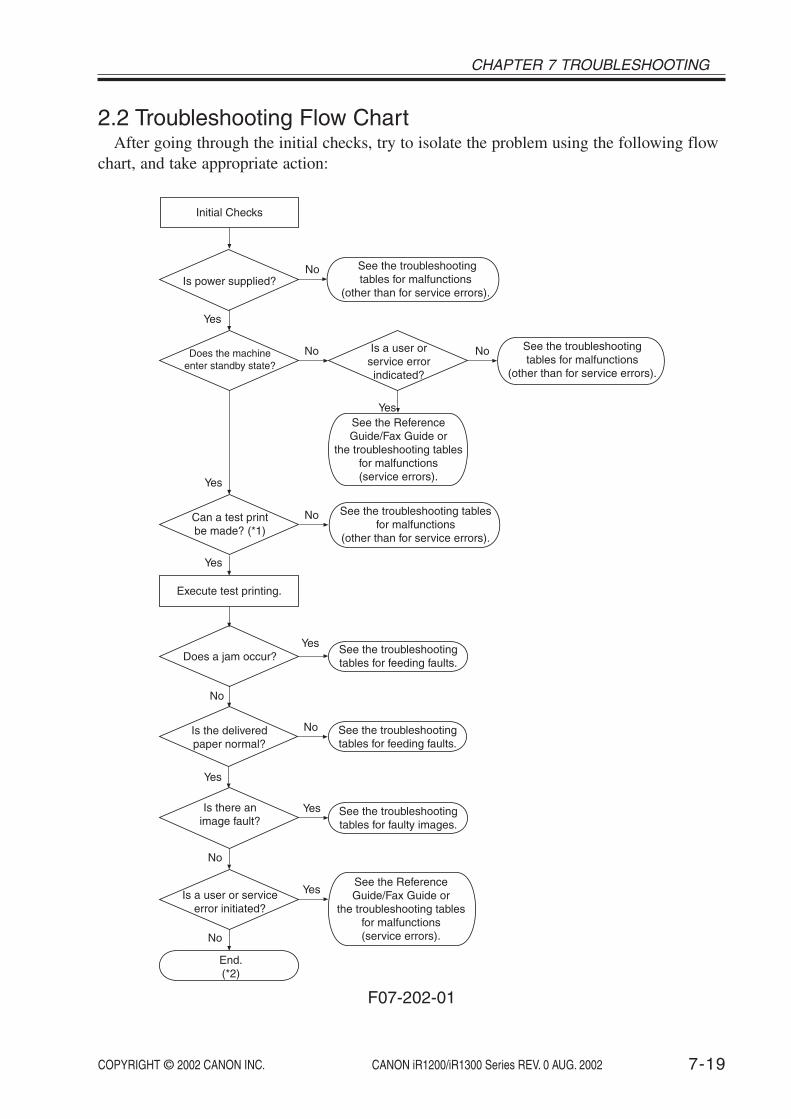
COPYRIGHT © 2002 CANON INC. 2000 2000 2000 2000 CANON iR1200/iR1300 Series REV. 0 AUG. 2002 7-19
CHAPTER 7 TROUBLESHOOTING
2.2 Troubleshooting Flow ChartAfter going through the initial checks, try to isolate the problem using the following flow
chart, and take appropriate action:
Does the machineenter standby state?
Execute test printing.
Does a jam occur?See the troubleshootingtables for feeding faults.
See the troubleshootingtables for malfunctions
(other than for service errors).
Is there animage fault?
See the troubleshootingtables for faulty images.
See the ReferenceGuide/Fax Guide or
the troubleshooting tablesfor malfunctions(service errors).
End.(*2)
Is a user or serviceerror initiated?
No
Yes
Yes
No
No
Yes
No
Yes
Yes
NoIs a user orservice errorindicated?
Can a test printbe made? (*1)
No
See the ReferenceGuide/Fax Guide or
the troubleshooting tablesfor malfunctions(service errors).
See the troubleshooting tablesfor malfunctions
(other than for service errors).
Initial Checks
Is power supplied?See the troubleshootingtables for malfunctions
(other than for service errors).
No
Is the deliveredpaper normal?
See the troubleshootingtables for feeding faults.
No
Yes
Yes
Yes
F07-202-01

COPYRIGHT © 2002 CANON INC. 2000 2000 2000 2000 CANON iR1200/iR1300 Series REV. 0 AUG. 2002
CHAPTER 7 TROUBLESHOOTING
7-20
*1: When executing test printing, be sure to select the source of paper used by the userwhen the fault occurred.
*2: For malfunctions related to the ADF, see the descriptions of faults unique to machinesequipped with ADF functions. Likewise, if a malfunction occurs while printing from aPC or a fax communication, see its respective section (those unique to printer functionsor those unique to fax functions).
2.3 Making Checks in Response to an Image FaultWhen you have indicated an image fault using the troubleshooting flow chart, go through
the following before starting troubleshooting work that follows:
2.3.1 Checking the Originals Against the SymptomDetermine whether the fault is caused by the machine or the original:
a. The copy density is best set to index 5 ± 2.b. Originals with a bluish background tend to cause poor contrast; e.g., blue sheet, receipts.c. The density of the original affects its copies: e.g., a diazo copy original or an original
with a high transparency can produce output that can be mistaken for “foggy copies,”while originals prepared in light pencil can produce output that can be mistaken for“light” copies.
2.3.2 Copyboard Glass and White SheetIf the copyboard glass or the white sheet is soiled, wipe it with a moist cloth and then dry
wipe it. If the dirt is excessive, use alcohol and lint-free paper. If there are scratches, replaceit.

COPYRIGHT © 2002 CANON INC. 2000 2000 2000 2000 CANON iR1200/iR1300 Series REV. 0 AUG. 2002 7-21
CHAPTER 7 TROUBLESHOOTING
3 Troubleshooting Image Faults
3.1 Troubleshooting Procedure for Image FaultsBefore starting to investigate the cause of an image fault, be sure to find out wheather the
user is storing paper in the correct way and using paper of a recommended type. If the prob-lem is corrected using such paper, advise the user accordingly.
Too light Too dark Foggy vertically
Foggy horizontally
Fuzzy, black vertical lines
Fuzzy, black horizontally lines
Paper feed direction
Note:
Black lines(vertical)
Black lines(horizontal)
White lines(vertical)
White lines(horizontal)
White spots(vertical)
White spots(horizontal)
Soiled face Soiled back Fixing fault Left/rightdisplacement
Blurry image Poor sharpness(out of focus)
Blank Soiled blank
F07-301-01

COPYRIGHT © 2002 CANON INC. 2000 2000 2000 2000 CANON iR1200/iR1300 Series REV. 0 AUG. 2002
CHAPTER 7 TROUBLESHOOTING
7-22
3.1.1 The output is too light.
Image density1) Is the image density setting correct?• In the case of copier functions: PRINT EXPOSURE of COMMON
SETTINGS and STANDARD EXPOSURE of COPY SETTINGSon user mode menu.
• In the case of printer functions or fax functions, PRINT EXPO-SURE of COMMON SETTINGS on user mode menu.
NO: Correct the image density setting.Paper
2) Try paper fresh out of package (newly opened). Is the problem cor-rected?
YES: 1. The paper may be moist. Advise the user on the correct methodof storing paper.2. Advise the user that the use of non-recommended paper maynot bring about the best results.
General conditions3) Execute ‘PRINT test’. Is the output image normal? (See 3.21.5 of
Chapter 2.)YES: Go through steps 14) to 18).NO: Go to step 4).
General conditions4) Turn off the machine while an image is printing on the photosensi-
tive drum. Is the toner on the drum surface developed?YES: Go through steps 11) to 13).NO: Go through steps 5) to 10).
High-voltage contact (between cartridge and high-voltage spring)5) Is the high-voltage spring used to supply high voltage to the car-
tridge soiled? (Remove the cartridge to check.)YES: Clean it.
High-voltage contact (between high-voltage spring and DC controller PCB; J205, J207)6) Is the connection between the high-voltage spring and the DC con-
troller PCB (J205, J207) normal?NO: Correct it. If it cannot be corrected, replace the faulty part.

COPYRIGHT © 2002 CANON INC. 2000 2000 2000 2000 CANON iR1200/iR1300 Series REV. 0 AUG. 2002 7-23
CHAPTER 7 TROUBLESHOOTING
Connector7) Is the connection of the following connectors normal: J201 and
J204 on the DC controller PCB; J303, J304, J312, and J316 on theimage processor PCB; J3122 and J801 in the laser scanner unit?
NO: Connect them firmly. If a scratch is found in the flexible cable, re-place it.
Drum unit8) Try replacing the drum unit. Is the fault corrected?
YES: End.Developing unit
9) Try replacing the developing unit. Is the fault corrected?YES: End.
Laser scanner unit, DC controller PCB10) Try replacing the laser scanner unit. Is the problem corrected?
YES: End.NO: Replace the DC controller PCB.
Transfer guide11) Measure the transfer guide and other metal portions. Is the resis-
tance 0 ΩΩΩΩΩYES: Check the area around the toner guide for a piece of metal (e.g.,
screw).High-voltage contact (between transfer charging roller and high-voltage spring)
12) Is the high-voltage spring used to supply high voltage to the trans-fer charging roller soiled?
YES: Clean it.High-Voltage Contact (high-voltage spring and DC controller PCB; J209), Transfer chargingroller
13) Is the connection between the high-voltage spring and DC control-ler PCB (J209) normal?
YES: Replace the transfer charging roller.NO: Correct it. If it cannot be corrected, replace the faulty part.
Selfoc lens array (contact sensor)14) Clean the selfoc lens array of the contact sensor. Is the problem cor-
rected? (See 4.3.1 of Chapter 6.)YES: End.
Contact sensor LED intensity auto adjustment15) Execute contact sensor LED intensity auto adjustment. Is the prob-
lem corrected? (See 1.2.4.1 of Chapter 7.)YES: End.
COPYRIGHT © 2002 CANON INC. 2000 2000 2000 2000 CANON iR1200/iR1300 Series REV. 0 AUG. 2002
CHAPTER 7 TROUBLESHOOTING
7-24
Connector16) Is the connection of the following connectors normal: J501 and
J503 on the analog processor PCB; J317 on the image processorPCB; and J504 of the contact sensor?
NO: Connect them firmly. If the flexible cable has a scratch, replace it.Contact sensor
17) Try replacing the contact sensor. Is the problem corrected?YES: End.
Analog processor PCB, Image processor PCB18) Try replacing the analog processor PCB. Is the problem corrected?
YES: End.NO: Replace the image processor PCB.

COPYRIGHT © 2002 CANON INC. 2000 2000 2000 2000 CANON iR1200/iR1300 Series REV. 0 AUG. 2002 7-25
CHAPTER 7 TROUBLESHOOTING
3.1.2 The output is too dark.
Image density1) Is the image density setting correct?• In the case of copier functions: PRINT EXPOSURE of COMMON
SETTINGS and STANDARD EXPOSURE of COPY SETTINGSon user mode menu.
• In the case of printer functions or fax functions, PRINT EXPO-SURE of COMMON SETTINGS on user mode menu.
NO: Correct the image density setting.General condition
2) Execute ‘PRINT test’. Is the output image normal? (See 3.21.5 ofChapter 2.)
YES: Go through steps 9) to 13).NO: Go through steps 3) to 8).
High-voltage contact (between cartridge and high-voltage spring)3) Is the high-voltage spring used to supply high voltage to the car-
tridge soiled? (Remove the cartridge to check.)YES: Clean it.
High-voltage contact (between high-voltage spring and DC controller PCB; J205, J207)4) Is the connection between the high-voltage spring and the DC con-
troller PCB (J205, J207) normal?YES: Correct it. If it cannot be corrected, replace the faulty part.
Connector5) Is the connection of the following connectors normal: J201 and
J204 on the DC controller PCB; J303, J304, J312, and J316 on theimage processor PCB; J3122 and J801 in the laser scanner unit?
NO: Connect them firmly. If the flexible cable has a scratch, replace it.Drum unit
6) Try replacing the drum unit. Is the fault corrected?YES: End.
Developing unit7) Try replacing the developing unit. Is the fault corrected?
YES: End.Laser scanner unit, DC controller PCB
8) Try replacing the laser scanner unit. Is the problem corrected?YES: End.NO: Replace the DC controller PCB.

COPYRIGHT © 2002 CANON INC. 2000 2000 2000 2000 CANON iR1200/iR1300 Series REV. 0 AUG. 2002
CHAPTER 7 TROUBLESHOOTING
7-26
Selfoc lens array (contact sensor)9) Clean the selfoc lens array of the contact sensor. Is the problem cor-
rected? (See 4.3.1 of Chapter 6.)YES: End.
Contact sensor LED intensity auto adjustment10) Execute contact sensor LED intensity auto adjustment. Is the prob-
lem corrected? (See 1.2.4.1 of Chapter 7.)YES: End.
Connector11) Is the connection of the following connectors normal: J501 and
J503 on the analog processor PCB; J317 on the image processorPCB; J504 of the contact sensor?
NO: Connect them firmly. If the flexible cable has a scratch, replace it.Contact sensor
12) Try replacing the contact sensor. Is the problem corrected?YES: End.
Analog processor PCB, Image processor PCB13) Try replacing the analog processor PCB. Is the problem corrected?
YES: End.NO: Replace the image processor PCB.
3.1.3 The output is foggy vertically.3.1.4 The output has fuzzy, black vertical lines.
Transfer guide assembly1) Clean the transfer guide assembly. Is the problem corrected?
YES: End.Drum unit, Developing unit
2) Try replacing the drum unit. Is the fault corrected?YES: End.NO: Replace the developing unit.

COPYRIGHT © 2002 CANON INC. 2000 2000 2000 2000 CANON iR1200/iR1300 Series REV. 0 AUG. 2002 7-27
CHAPTER 7 TROUBLESHOOTING
3.1.5 The output is foggy horizontally.3.1.6 The output has fuzzy, black horizontal lines.
General conditions1) Execute ‘PRINT test’. Is the output image normal? (See 3.21.5 of
Chapter 2.)YES: Go through steps 4) to 8).NO: Go through steps 2) to 3).
Transfer guide assembly2) Clean the transfer guide assembly. Is the problem corrected?
YES: End.Drum unit, Developing unit
3) Try replacing the drum unit. Is the fault corrected?YES: End.NO: Replace the developing unit.
Selfoc lens array (contact sensor)4) Clean the selfoc lens array of the contact sensor. (See 4.3.1 of Chap-
ter 6.)YES: End.
Contact sensor LED intensity auto adjustment5) Execute contact sensor LED intensity auto adjustment. Is the prob-
lem corrected? (See 1.2.4.1 of Chapter 7.)YES: End.
Connector6) Is the connection of the following connectors normal: J501 and
J503 on the analog processor PCB; J317 on the image processorPCB; and J504 of the contact sensor?
NO: Connect them firmly. If the flexible cable has a scratch, replace it.Contact sensor
7) Try replacing the contact sensor. Is the problem corrected?YES: End.
Analog processor PCB, Image processor PCB8) Try replacing the analog processor PCB. Is the problem corrected?
YES: End.NO: Replace the image processor PCB.

COPYRIGHT © 2002 CANON INC. 2000 2000 2000 2000 CANON iR1200/iR1300 Series REV. 0 AUG. 2002
CHAPTER 7 TROUBLESHOOTING
7-28
3.1.7 The output has black lines (vertical).3.1.8 The output has black lines (horizontal).
Fixing inlet guide1) Clean the fixing inlet guide. Is the problem corrected?
YES: End.Drum unit
2) Try replacing the drum unit. Is the problem corrected?YES: End.
Developing unit, Fixing assembly3) Try replacing the developing unit. Is the problem corrected?
YES: End.NO: Replace the fixing assembly.
3.1.9 The output has white spots (vertical).3.1.10 The output has white lines (vertical).
General conditions1) Execute ‘PRINT test’. Is the output image normal? (See 3.21.5 of
Chapter 2.)YES: Go to step 5).NO: Go through steps 2) through 4).
Transfer charging roller2) Is the transfer charging roller soiled?
YES: Clean it. If the problem is not corrected, replace it.Drum unit
3) Try replacing the drum unit. Is the problem corrected?YES: End.
Developing unit, Fixing assembly4) Try replacing the developing unit. Is the problem corrected?
YES: End.NO: Replace the fixing assembly.
Contact sensor drive belt, Contact sensor drive rail5) Is the contact sensor drive belt normal?
YES: Clean the surface of the contact sensor drive rail with alcohol;thereafter, apply a small amount of lubricant (MOLYKOTE EM-50L).
NO: Replace the contact sensor drive belt.

COPYRIGHT © 2002 CANON INC. 2000 2000 2000 2000 CANON iR1200/iR1300 Series REV. 0 AUG. 2002 7-29
CHAPTER 7 TROUBLESHOOTING
3.1.11 The output has white spots (horizontal).3.1.12 The output has white lines (horizontal).
Static eliminator1) Is the static eliminator soiled?
YES: Clean it.Back of copyboard glass (back of shading plate; dirt)
2) Try cleaning the back of the shading plate of the copyboard glass.Is the problem corrected?
YES: End.Shading position
3) Change the setting of No. 19 under ‘#6 SCANNER’ in service mode.Is the problem corrected?
YES: End.Transfer charging roller
4) Is the transfer charging roller soiled?YES: Clean it. If the problem is not corrected, replace it.
Drum unit5) Try replacing the drum unit. Is the problem corrected?
YES: End.Developing unit, Fixing assembly
6) Try replacing the developing unit. Is the problem corrected?YES: End.NO: Replace the fixing assembly.

COPYRIGHT © 2002 CANON INC. 2000 2000 2000 2000 CANON iR1200/iR1300 Series REV. 0 AUG. 2002
CHAPTER 7 TROUBLESHOOTING
7-30
3.1.13 The output is soiled.
Rollers (manual feed pickup roller, registration roller, fixing film, delivery roller), Photosen-sitive drum, Cartridge, Contact sensor
1) Is the problem at specific intervals?YES: Identify the cause by referring to T07-301-01, and clean it. (If it is
the photosensitive drum, replace the drum unit.)If the problem is not corrected, replace it.
NO: Check for drops of toner from the cartridge.If the problem occurs only in copy images, clean the selfoc lensarray of the contact sensor.
Image Faults by Component
Diam-eter*1
38.032.0
14.313.912.016.030.014.624.020.412.4
Imagefault
interval*1
--
44.943.837.342.093.343.775.464.139.0
Whitespot
√√√
Soiling
√
*2 *2
√
√ *2
√
Soiledback
√ *2
√√
√ *2
√ *2
Fixingfault
√√
Blurring
√√
Poorsharp-ness
√√√√
Component
Cassette pickup rollerManual feed pickuprollerVertical path rollerRegistration rollerPrimary charging rollerDeveloping cylinderPhotosensitive drumTransfer charging rollerFixing filmFixing pressure rollerDelivery roller
*1: Approximate; in mm.*2: Can be caused by dirt from the roller.
T07-301-01
Type of image fault

COPYRIGHT © 2002 CANON INC. 2000 2000 2000 2000 CANON iR1200/iR1300 Series REV. 0 AUG. 2002 7-31
CHAPTER 7 TROUBLESHOOTING
3.1.14 The back of the output is soiled.
Paper1) Is the paper soiled?
YES: Replace the paper.Fixing pressure roller
2) Execute fixing pressure roller cleaning. Is the problem correct? (See4.1.1 of Chapter 6.)
YES: Advise the user to clean the fixing pressure roller periodically.Transfer guide
3) Is the surface of the transfer guide soiled with toner?YES: Clean it.
Static eliminator4) Is the static eliminator soiled with toner?
YES: Clean it.Rollers (cassette pickup roller, vertical path roller, registration roller, transfer charging roller,fixing pressure roller), Paper path
5) Is the problem noted at specific internals?YES: Isolate the cause by referring to T07-301-01, and clean it.
If the problem is not corrected, replace the part.NO: Clean the paper path. If the problem cannot be corrected, replace
the part.

COPYRIGHT © 2002 CANON INC. 2000 2000 2000 2000 CANON iR1200/iR1300 Series REV. 0 AUG. 2002
CHAPTER 7 TROUBLESHOOTING
7-32
3.1.15 The output has a fixing fault.
Paper1) Try paper fresh out of package (newly opened). Is the problem cor-
rected?YES: 1. The paper may be moist. Advise the user on the correct method
of storing paper.2. Advise the user that the use of non-recommended paper may notbring about the best results in terms of fixing.
Fixing pressure roller2) Execute fixing pressure roller cleaning. Is the problem corrected?
(See 4.1.1 of Chapter 6.)YES: Advise the user to clean the fixing locking roller periodically.
Paper selection (for manual feed)3) Is the setting of paper selection suited to the type of paper placed in
the manual feed tray?NO: Correct the setting.
Connector4) Is the connection of the connector J107 on the power supply PCB
normal?NO: Connect it firmly.
Fixing pressure roller5) Is the surface of the fixing pressure roller normal?
NO: Clean the fixing locking roller. If it has a scratch, replace it.Fixing film unit
6) Try replacing the fixing film unit. Is the problem corrected?YES: End.
Fixing pressure roller (nip), Power supply PCB7) Is the nip of the fixing pressure roller correct? (See 1.1 of Chapter
7.)NO: Replace the fixing assembly. If the problem is not corrected after
replacement, replace the power supply PCB.

COPYRIGHT © 2002 CANON INC. 2000 2000 2000 2000 CANON iR1200/iR1300 Series REV. 0 AUG. 2002 7-33
CHAPTER 7 TROUBLESHOOTING
3.1.16 The output has left/right displacement.
Original1) Is the original placed correctly?
NO: Place it correctly.Paper
2) Is the paper curled appreciably?YES: Replace the paper.
Stack3) Is the amount of paper placed in the cassette more than allowed?
YES: Advise the user on the limit imposed on the amount of paper.Left/right edge read start position adjustment, DC controller PCB
4) Execute left/right edge read start position adjustment. Is the prob-lem corrected? (See 1.2.4.3 of Chapter 7.)
YES: End.NO: Replace the DC controller PCB.
3.1.17 The output has a blurry image.
General conditions1) Execute ‘PRINT test’. Is the output image normal? (See 3.21.5 of
Chapter 2.)YES: Go through steps 4) and 5).NO: Go through steps 2) and 3).
Transfer charging roller, Photosensitive drum2) Is the problem noted at specific intervals?
YES: Identify the cause by referring to T07-301-1, and replace it. (If thephotosensitive drum is the case, replace the drum unit.)If the problem cannot be corrected, check its drive system (e.g.,gears).
Laser scanner unit, DC controller PCB3) Try replacing the laser scanner unit. Is the problem corrected?
YES: End.NO: Replace the DC controller PCB.
Contact sensor drive belt4) Is the contact sensor drive belt normal?
NO: Replace the contact sensor drive belt.Contact sensor drive rail, reader motor
5) Move the contact sensor slowly. Does it move smoothly?YES: Replace the reader motor.NO: Check the surface of the contact sensor drive rail for foreign mat-
ter; if there is any, remove it. If it is soiled, clean it with alcohol,and then apply a small amount of lubricant (MOLYKOTE EM-50L).

COPYRIGHT © 2002 CANON INC. 2000 2000 2000 2000 CANON iR1200/iR1300 Series REV. 0 AUG. 2002
CHAPTER 7 TROUBLESHOOTING
7-34
3.1.18 The output has poor sharpness (out of focus).
General conditions1) Execute ‘PRINT test’. Is the output image normal? (See 3.21.5 of
Chapter 2.)YES: Go to step 5).NO: Go through steps 2) and 5).
Sharpness setting2) Change the setting of ‘SHARPNESS’ under ‘COPY SETTINGS’ on
the user mode menu. Is the problem corrected?YES: End.
High-voltage contact (high-voltage spring and DC controller PCB; J205, J207, J209)3) Is the high-voltage spring used to supply high voltage to the car-
tridge soiled? (Remove the cartridge to check.)High-voltage contact (high-voltage spring; J205, J207, J209 on DC controller PCB)
4) Is the connection between the high-voltage spring and the connec-tors (J205, J207, J209) on the DC controller PCB normal?
NO: Correct the connection. If the problem is not corrected, replace thefaulty part.
Drum unit (primary charging roller, photosensitive drum), Developing cylinder, Transfercharging roller, Contact sensor drive rail
5) Is the problem noted at specific intervals?YES: Identify the cause by referring to T07-301-01, and replace it. (If
the machine has the ADF, the ADF need not be removed.)NO: Check the surface of the contact sensor drive rail for foreign mat-
ter; if there is any, remove it. If it is solenoid, clean it with alcohol,and then apply a small amount of lubricant (MOLYKOTE EM-50L).

COPYRIGHT © 2002 CANON INC. 2000 2000 2000 2000 CANON iR1200/iR1300 Series REV. 0 AUG. 2002 7-35
CHAPTER 7 TROUBLESHOOTING
3.1.19 The output is blank.General conditions
1) Execute ‘PRINT test’. Is the output image normal? (See 3.21.5 ofChapter 2.)
YES: Go through steps 12) to 15).NO: Go to step 2).
General condition2) Turn off the power while an image is being printed on the photo-
sensitive drum. Is the toner image developed on the drum surface?YES: Go through steps 9) to 11).NO: Go through steps 3) to 8).
High-voltage contact (between cartridge and high-voltage spring)3) Is the high-voltage spring used to supply high voltage to the car-
tridge soiled? (Remove the cartridge to check.)YES: Clean it.
High-voltage contact (between high-voltage spring and DC controller PCB; J205, J207)4) Is the connection between the high-voltage spring and the connec-
tors (J205, J207) on the DC controller normal?NO: Correct it. If the problem cannot be corrected, replace the faulty
part.Connectors
5) Is the connection of the following connectors on the DC controllerPCB normal: J201 and J204 on the DC controller PCB; J303, J304,J312, and J316 on the image processor PCB; J3122, and J801 of thelaser scanner unit?
NO: Connect them firmly. If the flexible cable has a scratch, replace it.Drum unit
6) Try replacing the drum unit. Is the fault corrected?YES: End.
Developing unit7) Try replacing the developing unit. Is the fault corrected?
YES: End.Laser scanner unit, DC controller PCB
8) Try replacing the laser scanner unit. Is the problem corrected?YES: End.NO: Replace the DC controller PCB.
Transfer guide9) Measure the transfer guide and other metal areas. Is the resistance
0 Ω.Ω.Ω.Ω.Ω.YES: Check the area around the transfer guide for pieces of metal (e.g.,
screw).

COPYRIGHT © 2002 CANON INC. 2000 2000 2000 2000 CANON iR1200/iR1300 Series REV. 0 AUG. 2002
CHAPTER 7 TROUBLESHOOTING
7-36
High-voltage contact (between transfer charging roller and high-voltage spring)10) Is the high-voltage spring used to supply high voltage to the trans-
fer charging roller soiled?YES: Clean it.
High-voltage contact (between high-voltage spring and DC controller PCB; J209), Transfercharging roller
11) Is the connection between the high-voltage spring and the DC con-troller PCB (J209) normal?
YES: Replace the transfer charging roller.NO: Correct it. If the problem cannot be corrected, replace the faulty
part.Contact sensor LED intensity auto adjustment
12) Execute contact sensor LED intensity auto adjustment. Is the prob-lem corrected? (See 1.2.4.1 of Chapter 7.)
YES: End.Connector
13) Is the connection of the following connectors normal: J501 andJ503 on the analog processor PCB; J317 on the image processorPCB; J504 of the contact sensor.
NO: Connect them firmly. If the flexible cable has a scratch, replace it.Contact sensor
14) Try replacing the contact sensor. Is the problem corrected?YES: End.
Analog processor PCB, Image processor PCB15) Try replacing the analog processor PCB. Is the problem corrected?
YES: End.NO: Replace the image processor PCB.

COPYRIGHT © 2002 CANON INC. 2000 2000 2000 2000 CANON iR1200/iR1300 Series REV. 0 AUG. 2002 7-37
CHAPTER 7 TROUBLESHOOTING
3.1.20 The output is solid black.
General conditions1) Execute ‘PRINT test’. Is the output image normal? (See 3.21.5 of
Chapter 2.)YES: Go through steps 6) to 9).NO: Go through steps 2) to 5).
High voltage contact (between primary charging roller and high-voltage spring)2) Is the high-voltage spring used to supply power to the cartridge
soiled? (Remove the cartridge to check.)YES: Clean it.
High-voltage contact (high-voltage spring and DC controller PCB; J205)3) Is the connection between the high-voltage spring and the DC con-
troller PCB (J205) normal?NO: Correct it. If the problem cannot be corrected, replace the faulty part.
Drum unit4) Try replacing the drum unit. Is the problem corrected?
YES: End.Developing unit, DC controller PCB
5) Try replacing the developing unit. Is the problem corrected?YES: End.NO: Replace the DC controller PCB.
Contact sensor LED intensity auto adjustment adjustment6) Execute contact sensor LED intensity auto adjustment adjustment.
Is the problem corrected? (See 1.2.4.1 of Chapter 7.)YES: End.
Connector7) Is the connection of the following controller normal: J501 and J503
on the analog processor PCB; J317 on the image processor PCB;J504 of the contact sensor?
NO: Connect them firmly. If the flexible cable has a scratch, replace it.Contact sensor
8) Try replacing the contact sensor. Is the problem corrected?YES: End.
Analog processor PCB, Image processor PCB9) Try replacing the analog processor PCB. Is the problem corrected?
YES: End.NO: Replace the image processor PCB.

COPYRIGHT © 2002 CANON INC. 2000 2000 2000 2000 CANON iR1200/iR1300 Series REV. 0 AUG. 2002
CHAPTER 7 TROUBLESHOOTING
7-38
4 Troubleshooting Malfunctions
4.1 Troubleshooting Malfunctions (service error)
E000The error history indicates any of the following error codes 4 times: E001,E002, E003.
Action 1) Clear the error.Execute ‘#4 PRINTER RESET” under ‘#7 PRINTER’ in service mode toclear the error.; then, turn back on the power.
E001000 The main thermistor detects 230°C/446°F or higher for 1 sec or
more.001 The sub thermistor detects 300°C/572°F or higher for 0.2 sec or
more.
Main cause The fixing film unit is faulty (thermistor short circuit). The power supplyPCB is faulty. The DC controller PCB is faulty.
Action 1. MalfunctionTurn off the power; wait for 10 min, and turn it on. Is the problem cor-rected?
YES: End.2. Fixing film unitCheck the connector (4-pin) of the thermistor for electrical continuity: 1-2and 3-4. Is it 0 Ω?
YES: Replace the fixing film unit.3. Power supply PCB, DC controller PCBTry replacing the power supply PCB. Is the problem corrected?
NO: Replace the DC controller PCB.

COPYRIGHT © 2002 CANON INC. 2000 2000 2000 2000 CANON iR1200/iR1300 Series REV. 0 AUG. 2002 7-39
CHAPTER 7 TROUBLESHOOTING
E002000 During printing, the main thermistor detects 0°C/32°F or lower for
1 sec or more continuously.About 10 sec or later after power-on/start of printing, the mainthermistor detects less than 120°C/248°F for 1 sec or more con-tinuously.After power-on/start of printing, the reading of the main thermistordoes not reach the target value -15°C/11°F or higher within 75 sec.
001 About 10 sec or later after the heater is supplied with power, thesub thermistor detects less than 75°C/167°F for 2 sec or more con-tinuously.
Main cause The fixing film unit is faulty (main thermistor fault, sub thermistor fault,thermal fuse blow, fixing heater fault). The power supply PCB is faulty. TheDC controller PCB is faulty.
Action See the descriptions for E003.
E003During printing, the main thermistor detects less than 120°C/248°F for 1sec or more continuously.
Main cause The fixing film unit is faulty (main thermistor fault, thermal fuse blow, fix-ing heater fault). The power supply PCB is faulty. The DC controller PCBis faulty.
Action 1. MalfunctionTurn off the power; wait for 10 min, and turn on the power. Is the problemcorrected?
YES: End.2. WiringIs the wiring from the DC controller PCB to the fixing film unit normal?
NO: Correct the wiring.3. Fixing film unitTry replacing the fixing film unit. Is the problem corrected?
YES: End.4. Power supply PCB, DC controller PCBTry replacing the power supply PCB. Is the problem corrected?
YES: End.NO: Replace the DC controller PCB.

COPYRIGHT © 2002 CANON INC. 2000 2000 2000 2000 CANON iR1200/iR1300 Series REV. 0 AUG. 2002
CHAPTER 7 TROUBLESHOOTING
7-40
E100About 1.5 sec after the scanner drive signal output, the BDI* signal is notdetected 3 times or more for 1.0 sec.While the laser is ON, the BD signal cycle is not as indicated for 0.5 ormore continuously.
Main cause The laser driver/BD PCB is faulty (laser activation failure, BD detectionfault). The DC controller PCB is faulty. The image processor PCB is faulty.
Action 1. WiringIs the wiring from the DC controller PCB to the laser scanner unit normal?
NO: Correct the wiring2. Laser scanner unitTry replacing the laser scanner unit. Is the problem corrected?
YES: End.3. DC controller PCB, Image processor PCBTry replacing the DC controller PCB. Is the problem corrected?
YES: End.NO: Replace the image processor PCB.
E110The scanner fails to reach the target speed of rotation 10 sec after the laserscanner motor reaches constant speed state.
Main cause The laser scanner motor is faulty. The DC controller PCB is faulty.
Action 1. Laser scanner unit, DC controller PCBTry replacing the laser scanner unit. Is the problem corrected?
YES: End.NO: Replace the DC controller PCB.

COPYRIGHT © 2002 CANON INC. 2000 2000 2000 2000 CANON iR1200/iR1300 Series REV. 0 AUG. 2002 7-41
CHAPTER 7 TROUBLESHOOTING
E805While the fan is rotating, fan lock state is detected for 10 sec or more con-tinuously.
Main cause The fan is faulty. The DC controller PCB is faulty. The image processorPCB is faulty.
Action 1. Foreign matterIs there any foreign matter that hinders the rotation of the heat dischargefan?
YES: Remove the foreign matter.2. Wiring, ConnectionAre the wiring and connection (connectors) of the fan normal?
NO: Correct them.3. FanTry replacing the fan. Is the problem corrected?
YES: End.4. DC controller PCB/Image processors PCBTry replacing the DC controller PCB. Is the problem corrected?
YES: End.NO: Replace the image processor PCB.
E810The case that the toner bottle is detected, but not the cartridge.
Main cause The DC controller PCB is faulty. The cartridge is faulty.
Action 1. High-voltage contact (between machine and the developing unit)Is the high-voltage spring used to supply high voltage to the developingunit soild?
YES: Clean it.2. High-voltage contact (between high-voltage spring and DC controllerPCB; J207)Is the connection between the high-voltage spring and the DC controllerPCB(J207) normal?
NO: Correct the connection. If the problem cannot be corrected, replacethe faulty part.
3. Developing unit, DC controller PCBReplace the developing unit. Is the problem corrected?
YES: End.NO: Replace the DC controller PCB.

COPYRIGHT © 2002 CANON INC. 2000 2000 2000 2000 CANON iR1200/iR1300 Series REV. 0 AUG. 2002
CHAPTER 7 TROUBLESHOOTING
7-42
4.2 Troubleshooting Malfunctions (other than service error)4.2.1 Power is absent.
Making Checks1) Check to see if the LED (upper) on the image processor PCB is ON.
YES: Go to step 5).NO: Go through steps 2) to 4).
Power plug2) Is the power plug connected to the power outlet?
NO: Connect it firmly.Power cord
3) Is the power cord connected to the machine? Moreover, is thepower cord normal?
NO: Connect it. If it is faulty, replace it.Source power
4) Is the rated voltage present at the power outlet?YES: Replace the power supply PCB. If the fuse has blown, find and re-
move the cause.NO: The problem is not of the machine. Advise the user.
ROM-DIMM, Image processor PCB5) Check to see if the problem is corrected when the ROM-DIMM is
re-mounted.YES: End.NO: Replace the ROM-DIMM. If it cannot be corrected, replace the im-
age processor PCB.
4.2.2 The LCD fails to operate.
Connector1) Is the connection of the following connectors normal: J401 and
J402 on the control panel PCB; J315 on the image processor PCB;J4020 on the LCD?
NO: Connector them firmly. If the flexible cable has a scratch, replaceit.
LCD2) Try replacing the LCD. Is the problem corrected?
YES: End.Control panel PCB/Image processor PCB
3) Try replacing the control panel PCB. Is the problem corrected?YES: End.NO: Replace the image processor PCB.

COPYRIGHT © 2002 CANON INC. 2000 2000 2000 2000 CANON iR1200/iR1300 Series REV. 0 AUG. 2002 7-43
CHAPTER 7 TROUBLESHOOTING
4.2.3 The contact sensor fails to move.
Contact sensor, Spacer of contact sensor1) Are the contact sensor and the spacers of the contact sensor
mounted correctly?NO: Mount them correctly.
Contact sensor drive belt2) Is the contact sensor drive belt normal?
NO: Replace the contact sensor drive belt.Contact sensor drive rail
3) Move the contact sensor slowly. Does it move smoothly?NO: Check the surface of the contact sensor drive rail for foreign mat-
ter, and remove any foreign matter. If it is soiled, clean it with alco-hol, and apply a small amount of lubricant (MOLYKOTE EM-50L).
Connector4) Is the connection between the connector J310 on the image proces-
sor PCB and the connector of the reader motor normal?NO: Correct the connection.
Reader motor, Image processor PCB5) Try replacing the reader motor. Is the problem corrected?
YES: End.NO: Replace the image processor PCB.
4.2.4 The contact sensor LED fails to go ON.
Connector1) Is the connection of the following sensors normal: J501 and J503 on
the analog processor PCB; J317 on the image processor PCB; J504on the contact sensors?
NO: Correct the connection. If the flexible cable has a scratch, replaceit.
Contact sensor2) Try replacing the contact sensor. Is the problem corrected?
YES: End.Analog processor PCB, Image processor PCB
3) Try replacing the analog processor PCB. Is the problem corrected?YES: End.NO: Replace the image processor PCB.

COPYRIGHT © 2002 CANON INC. 2000 2000 2000 2000 CANON iR1200/iR1300 Series REV. 0 AUG. 2002
CHAPTER 7 TROUBLESHOOTING
7-44
4.2.5 The speaker fails to generate sound.
Volume setting1) Is the volume setting in user mode menu correct?
NO: Correct the setting.Connector
2) Is the connection of the following connectors normal: J315 on theimage processor PCB; J401 and J404 on the control panel PCB?
NO: Correct the connection. If the flexible cable has a scratch, replace it.Speaker
3) Try replacing the speaker. Is the problem corrected?YES: End.
Control panel PCB, Image processor PCB4) Replace the control panel PCB. Is the problem corrected?
YES: End.NO: Replace the image processor PCB.
4.2.6 The message “CHECK TONER/DRUM CRG” fails to go OFF.
Condition of toner bottle setup1) Is the toner bottle set in properly?
NO: Set the toner bottle properly.Flag of toner bottle sensor (PS11)
2) Is the flag of the toner bottle sensor (PS11) displaced or damaged?YES: Correct it. If damaged, replace it.
High-voltage contact (between machine and cartridge)3) Is the high-voltage spring used to supply high voltage to the car-
tridge soiled?YES: Clean it.
High-voltage contact (between high-voltage spring and DC controller PCB; J205)4) Is the connection between the high-voltage spring and the DC con-
troller PCB (J205) normal?NO: Correct the connection. If the problem cannot be corrected, replace
the faulty part.Drum unit
5) Replace the drum unit. Is the problem corrected?YES: End.
Developing unit, DC controller PCB6) Replace the developing unit. Is the problem corrected?
YES: End.NO: Replace the DC controller PCB.
COPYRIGHT © 2002 CANON INC. 2000 2000 2000 2000 CANON iR1200/iR1300 Series REV. 0 AUG. 2002 7-45
CHAPTER 7 TROUBLESHOOTING
4.2.7 The message “SUPPLY REC. PAPER DRAWER:” fails to go OFF.(cassette)
Cassette1) Is the cassette fitted correctly?
NO: Fit the cassette correctly.Spring (holding plate)
2) Is the holding plate of the cassette in up position?NO: Check the case holding plate, and correct if necessary. If damaged,
replace it.Flag of cassette paper sensor (PS103)
3) Is the flag of the cassette paper sensor displaced or damaged?YES: Correct it. If damaged, replace it.NO: Replace the DC controller PCB.
4.2.8 The message “SUPPLY REC. PAPER S.B.:” fails to go OFF. (manualfeed tray)
Flag of manual feed tray paper sensor (PS4)1) Is the flag of the manual feed tray paper sensor (PS4) displaced or
damaged?YES: Correct it. If damaged, replace it.
Connector2) Is the connection of the following connectors normal: J303 and
J308 on the image processor PCB; J204 on the DC controller PCB;J3081 on the manual feed tray paper sensor (PS4)?
NO: Correct the connection.Manual feed tray paper sensor (PS4)
3) Try replacing the manual feed paper sensor (PS4). Is the problemcorrected?
YES: End.DC controller PCB, Image processor PCB
4) Try replacing the DC controller PCB. Is the problem corrected?YES: End.NO: Replace the image processor PCB.

COPYRIGHT © 2002 CANON INC. 2000 2000 2000 2000 CANON iR1200/iR1300 Series REV. 0 AUG. 2002
CHAPTER 7 TROUBLESHOOTING
7-46
4.2.9 The message “REC. PAPER JAM SLIDE PLATEN LEFT” fails to go OFF.
General conditions1) Check to find out which of the following sensors is faulty. (See 6.1
of Chapter 7.)• cassette paper sensor (PS103)• manual feed tray paper sensor (PS4)
If both the sensors above are normal, the cause is with either of thesensors below. Follow the check procedure from Step 2, with eachof the sensors below.
• delivery sensor (PS3)• paper leading edge sensor (PS102)
Sensor flag2) Is the flag of the sensor identified in step 1) damaged or displaced?
YES: Correct it. If damaged, replace it.Connector
3) Is the connection between the connector for the sensor identified instep 1) and the image processor PCB, DC controller PCB, andpower supply PCB normal?
• In the case of the manual feed tray paper sensor (PS4), J303 andJ308 of the image processor PCB and J204 of the DC controllerPCB.
• In the case of the delivery sensor (PS3), J106 and J109 of the powersupply PCB and J202 of the DC controller PCB.
NO: Correct the connection.Sensor
4) If the faulty sensor is any of the following, try replacing it. Is theproblem corrected?
• manual feed tray paper sensor (PS4)• delivery sensor (PS3)
YES: End.DC controller PCB, Image processor PCB, Power supply PCB
5) 1. If the cassette paper sensor (PS103) or the paper leading edgesensor (PS102) is faulty, try replacing the DC controller PCB. Isthe problem corrected?
2. If the manual feed tray paper sensor (PS4) is faulty, try replacingthe image processor PCB. Is the problem corrected?
3. If the delivery sensor (PS3) is faulty, try replacing the power sup-ply PCB. Is the problem corrected?
YES: End.NO: If the manual feed tray paper sensor (PS4) or the delivery sensor
(PS3) is faulty, replace the DC controller PCB.

COPYRIGHT © 2002 CANON INC. 2000 2000 2000 2000 CANON iR1200/iR1300 Series REV. 0 AUG. 2002 7-47
CHAPTER 7 TROUBLESHOOTING
4.2.10 The message “PLATEN/COVER IS OPEN CLOSE PLATEN/COVER” fails to go OFF.
Sensor flag1) Is the reader unit slide detecting switch (SW1) damaged or dis-
placed?YES: Correct it. If damaged, replace it.
Connector2) Check the status of connection of the reader unit slide detecting
switch (SW1) with the J3140 connector of the toner supply coveropen/close detecting switch (SW2). Also check SW1 connecting sta-tus with the J314 connector on the image processor PCB. Is theswitch connected properly to both parts?
NO: Correct the connection.Reader unit slide detecting switch (SW1), Image processor PCB
3) Try replacing the reader unit slide detecting switch (SW1). Is theproblem corrected?
YES: End.NO: Replace the image processor PCB.
COPYRIGHT © 2002 CANON INC. 2000 2000 2000 2000 CANON iR1200/iR1300 Series REV. 0 AUG. 2002
CHAPTER 7 TROUBLESHOOTING
7-48
4.3 Troubleshooting Malfunctions (if equipped with ADF functions)
4.3.1 Original pickup fails.
General conditions1) Does the ADF motor rotate?
YES: Go through steps 2) through 4).NO: Go to step 5) through 6).
General conditions2) Is the original separation roller rotating?
NO: Check the gear and timing belt used to transmit the drive of theADF motor (M3). If scratched, replace it.
Original pickup roller descent/Original stopper ascent mechanism3) Does the original pickup roller move down and the original stopper
move up during original pickup?NO: Check the parts of the original separation roller unit, and correct
any fault. If scratched, replace it.Rollers (separation roller unit)
4) Is the surface of each roller of the separation roller unit normal?NO: Replace the faulty roller.
ADF motor (connection)5) Is the ADF motor harness connected firmly?
NO: Connect it firmly.ADF motor (M3), Image processor PCB
6) Try replacing the ADF motor (M3). Is the problem corrected?YES: EndNO: Replace the image processor PCB.

COPYRIGHT © 2002 CANON INC. 2000 2000 2000 2000 CANON iR1200/iR1300 Series REV. 0 AUG. 2002 7-49
CHAPTER 7 TROUBLESHOOTING
4.4 Troubleshooting Malfunctions (printer functions)If the results of all work in the troubleshooting flow in 2.2 are good and yet a fault occurs
when a printer function is used (printing from a PC), go through the following:
4.4.1 Printing fails to start.4.4.2 Printing stops in the middle.
Status check1) Can test print be done from the PC?
YES: Explain the user that the trouble cause is probably not within themachine.
Operating environment2) Is the PC used meet the requirements of the machine?
NO: Explain the user that PC environment must satisfy the requirementsof the machine. (Refer to Quick Start Guide.)
Status check3) Run the troubleshooter of the machine from the PC. Are the check
results normal?NO: Correct the problem according to the description displayed as the
check results.Connection of interface cables to PC
4) Is the connection of the interface cables normal?NO: Connect securely. Replace the cable if it has scratches, etc.
PC settings5) Are the PC settings correct? (Printer port setting, printer driver
selection, etc.)NO: Correct the settings. (Refer to Quick Start Guide, Print Guide, and
operation manual of the PC.)Interface cables
6) Are the cables meet the specifications of the model?NO: Replace the cables with the ones that satisfy the specifications of
the model.USB cable specifications: 5 m or shorterParallel interface cable specifications: 3 m or shorter (compliant toIEEE1284, for bi-directional communication)
Printer driver7) Is the problem remedied after reinstalling an optimal printer
driver?YES: End
COPYRIGHT © 2002 CANON INC. 2000 2000 2000 2000 CANON iR1200/iR1300 Series REV. 0 AUG. 2002
CHAPTER 7 TROUBLESHOOTING
7-50
Connector8) Is the connection of the printer controller PCB (J709) and the im-
age processor PCB (J318) normal?NO: Correct the connection. If the flexible cable has a scratch, replace
it.Printer controller PCB
9) Try replacing the printer controller PCB. Is the problem corrected?YES: End.NO: Replace the image processor PCB.

COPYRIGHT © 2002 CANON INC. 2000 2000 2000 2000 CANON iR1200/iR1300 Series REV. 0 AUG. 2002 7-51
CHAPTER 7 TROUBLESHOOTING
4.5 Troubleshooting(faults unique to models equipped with fax functions)
4.5.1 Troubleshooting Communication FaultsGo through the troubleshooting flow chart*; if you cannot reach the last step of the flow
of work and the fault occurs while a fax function is in use, go through the following: 2.2 ofChapter 7.
1) Find out the conditions in which the fault occurs in detail.a. operation used; i.e., number of pages, transmission mode, timing of error occurrence
(as before or after transmission), user of auto-dialingb. faulty image samples (store away; in the case of reception)c. LCD indication at time of the faultd. activity report at time of the faulte. user information: abbreviation, telephone number, fax number, model namef. other-party information: name, telephone number, fax number, modelg. frequency of occurrence, type of errorh. fax condition at other party; number of pages transmitted/received, auto or manual; re-
ception condition
REF.
If you are visiting in response to a report, try to obtain a system dump listfor a. and g.
2) Go through the following flow chart to conduct a communication test.• Try a test several times for each item using the actual telephone line; check the symp-
toms, and keep a record.
3) Evaluate all the information you have colleted, and take appropriate action based oncomprehensive evaluation.
REF.
If the other party is a non-Canon machine and no fault is found in the user’smachine, arrange for an investigation of the other party. Advise the user onthe situation.

COPYRIGHT © 2002 CANON INC. 2000 2000 2000 2000 CANON iR1200/iR1300 Series REV. 0 AUG. 2002
CHAPTER 7 TROUBLESHOOTING
7-52
• Troubleshooting a Communication Fault (Canon machine in use)Try a 3-station communication as indicated in the following diagram:
Trouble
Start
TX/RX?
TX
NG
NG NG
NG
OK
OK OK
OK
A to C C to A
Check A Check A
Check the line Check the lineCheck Band the line
Check Band the line
C to B B to C
RX
FAX:A FAX:B
FAX:C
A: machine of the userB: machine of the other partyC: test machine within the same block (best if of the same model as A)
F07-405-01

COPYRIGHT © 2002 CANON INC. 2000 2000 2000 2000 CANON iR1200/iR1300 Series REV. 0 AUG. 2002 7-53
CHAPTER 7 TROUBLESHOOTING
4.5.2 Service Error Code OutputIf ‘1’ is set to service data #1 SSSW SW01 bit 0, an appropriate service error code will be
indicated on the following reports if a communication ends in error: communication controlreport, reception result report, error transmission report.
When an error occurs, you can generate a system dump list in service mode to check thecode.
4.5.3 Error CodesThe error codes used in the machine are defined as follows:
4.5.3.1 Transmission Level (ATT): No.07 of Service Soft Switch #2 MENU• Increase the transmission level:
Increase the setting so that it is closer to 0 dBm. (At 0 dBm, the LCD indicates ‘0’.)• Decrease the transmission level:
Decrease the setting so that it is closer to -15 dBm. (At -15 dBm, the LCD indicates‘15’.)
4.5.3.2 NL Equalizer: No.05 of Service Soft Switch #2 MENU• Adjust the NL equalizer:
Select ‘ON’.
4.5.3.3 Transmission Page Timer: SW12 of Service Soft Switch #1 SSSW• Increase the page timer setting:
To set both transmission and reception to the same time-out length, set SW12 as fol-lows:
8 min: bit 7, bit 1, bit 0 = 0, 0, 016 min: bit 7, bit 1, bit 0 = 0, 0, 132 min: bit 7, bit 1, bit 0 = 0, 1, 064 min: bit 7, bit 1, bit 0 = 0, 1, 1If you want to set transmission and reception to different time-out lengths, or use differ-
ent time-out lengths according to different image modes, you will have to set all bits (from7 through 0) accordingly.
4.5.3.4 T0 Timer: No.10 of Service Soft Switch #3 NUMERIC param.• Increase the T0 timer setting:
Increase the setting of No.10.The T0 timer is used to set the period of time in which a line connection is recognized
for transmission, i.e., in which the machine waits for a significant signal from the otherparty after dialing. The line will be disconnected if no significant signal is received duringthe period.

COPYRIGHT © 2002 CANON INC. 2000 2000 2000 2000 CANON iR1200/iR1300 Series REV. 0 AUG. 2002
CHAPTER 7 TROUBLESHOOTING
7-54
4.5.3.5 T1 Timer: No.11 of Service Soft Switch #3 NUMERIC param.• Increase the T1 timer setting:
Increase the setting of No.11.The T1 timer is used to set the period of time in which a line connection is recognized
for reception, i.e., in which the machine waits for a significant signal from the other partyafter transmission of DIS. The line will be disconnected if no significant signal is receivedduring the period.
4.5.3.6 RTN Signal Transmission Condition: No. 02, 03, and 04 of Service SoftSwitch #3 NUMERIC param.
• Loosen the RTN signal transmission condition:Increase the settings of No.02, 03, and 04.No.02 is used to set the ratio of the number of error lines to the total number of lines per
page (1% to 99%).No.03 is used to set the burst error (number of successive error lines identified as an er-
rors) ; (2 to 99 lines).No.04 is used to set the number of errors falling short of a burst error (1 to 99 times).
4.5.3.7 Echo Remedy• An echo remedy may be provided on the reception side as follows:
Echo Remedy 1 (by the receiving machine; adds a 1080-Hz tonal signal beforetransmission of CED):Set SW03 bit 7 of service soft switch #1 SSSW to ‘1’ so that a 1080-Hz tonal signal is
transmitted before transmission of CED.Echo Remedy 2 (by the receiving machine; changes the period in which the lowspeed signal is ignored after transmission of CFR):Set SW04 bit 4 of service soft switch #1 SSSW to ‘1’ so that the period in which the
low speed signal is ignored after transmission of CFR is changed from 700 to 1500 msec.
4.5.3.8 Echo Protect Tone: SW03 bit 1 of Service Soft Switch #1 SSSW• Add an echo protect tone to the V.29 modem signal for transmission:
When SW03 bit 1 is set to ‘1’, an echo protect tone will be added to high-speed trans-mission V.29 (at 9600 or 7200 bps) for transmission.
4.5.3.9 Number of Final Flag Sequences: SW04 bit 2 of Service Soft Switch #1SSSW
• Increase the number of final flag sequences:When SW04 bit 2 is set to ‘1’, the number of final flag sequences will be increased from
1 to 2 for a procedure signal (transmitted at 300 bps).

COPYRIGHT © 2002 CANON INC. 2000 2000 2000 2000 CANON iR1200/iR1300 Series REV. 0 AUG. 2002 7-55
CHAPTER 7 TROUBLESHOOTING
4.5.3.10 SubaddressA subaddress is used to indicate the location of a memory box in the other party (e.g., con-
fidential mailbox, polling box), and it consists of 20 or fewer characters (numerals, *, #,space). As log as the other party complies with the International Standards of ITU-T, the ma-chine can communicate with it by means of subaddresses.
At times, an ID number (referred to as a “password”) is used to restrict access to a loca-tion indicated by a subaddress.
With some models, polling based on subaddresses is called “selective polling”, and asubaddress used at time of polling is called a “selective polling address”.
4.5.3.11 PasswordA password used by a Canon facsimile machine may be any of the following:Password for Subaddress Communications:This is an ID number used for a subaddress communication and, as in the case of a
subaddress, it consists of 20 or fewer characters (numerals, *, #, space).Communication Password:This is an ID number used for a password communication. Some models use 4 decimal
characters (0000 through 9999), while some use 3 decimal characters (000 through 255).
Memo
Password Used When Making Settings:A password may also be used for memory lock Rx, call restriction, andother functions. Such a password consists of 4 decimal characters (0000through 9999), and it is important to remember that these passwords areused inside the machine and are not intended for communication proce-dures.
4.5.3.12 SignalsTonal Signal:
A tonal signal consists of sinusoidal waves of a specific frequency, and may be thoughtof as a sound carrying a meaning. CNG, CED, and ANSam are tonal signals.
Binary Signal:A binary signal is used to indicate the meaning of a procedure. It is either ‘1’ or ‘0’,
modulated according to frequency, and is used as G3 procedure signals.Procedure Signal:
It is a generic term for a tonal signal and a binary signal.Preamble:
It is a signal attached to the beginning of a binary signal, and is used to synchronize mo-dem signals for a procedure signal.
Image Signal:Of procedure signals, it is used for actual transmission of image data.
Significant Signal:It is a signal whose significance can be understood by a facsimile machine that receives
it, and it is free of a transmission error.
COPYRIGHT © 2002 CANON INC. 2000 2000 2000 2000 CANON iR1200/iR1300 Series REV. 0 AUG. 2002
CHAPTER 7 TROUBLESHOOTING
7-56
4.5.3.13 TimerT0 Timer:
It indicates the period of time in which a line connection is recognized during transmis-sion; specifically, the machine waits for a significant signal from the other party after dial-ing.
T1 Timer:It indicates the period of time in which a line connection is recognized during reception;
specifically, the machine waits for a significant signal from the together party after trans-mission of DIS.
T5 Timer:It is the period of time in which RR/RNR is transmitted during an ECM communication.

COPYRIGHT © 2002 CANON INC. 2000 2000 2000 2000 CANON iR1200/iR1300 Series REV. 0 AUG. 2002 7-57
CHAPTER 7 TROUBLESHOOTING
4.5.4 How to Record the ProtocolIf you are instructed to “record the comm unication procedure sound on a DAT or MD,
and ask the Technical Center for analysis”, refer to the following diagram for a generallyused method of connection:
Telephone line
G3 Recording Adaptor
DAT recorderor
MD recorder
Use Standard (SP) mode for recording.Set the recording level so that the sound of communicationcan clearly be heard with as little noise as possible when replayed.
LINE IN
FAX TELLINE
LINE
FAX
F07-405-02

COPYRIGHT © 2002 CANON INC. 2000 2000 2000 2000 CANON iR1200/iR1300 Series REV. 0 AUG. 2002
CHAPTER 7 TROUBLESHOOTING
7-58
4.5.5 Causes and Remedies for User Error CodesThe causes and remedies for individual user error codes are as follows:
#001 [TX] Document has jammed
The original is trapped in the feederRemove the document, and try again.The original is not of a standard size or thickness.1. Make a copy on A4/LTR paper in book mode, and transmit the output.2. If the original is too thin or too small, transmit it in book mode.Internal Fault1. Check the connection of the DS sensor (original sensor), DES sensor (registra-
tion sensor), and image processor PCB.2. Check the following to see if they operate normally: DS sensor (original sen-
sor), DES senor (registration sensor). (See 6.1 of Chapter 7.)3. Replace the DS sensor (original sensor) and the DES sensor (registration sen-
sor).4. Check the connection between the ADF motor and the image processor PCB.5. Make copies to find out if the ADF motor is operating normally.6. Replace the image processor PCB.
#003 [TX/RX] Document is too long, or page time-over
Cause:Remedy:Cause:
Remedy:
Cause:Remedy:
Cause:Remedy:
The length of a single page is too long.Make copies in book mode, and transmit the original in several divisions.The data of a single page is too large, exceeding the time allowed for transmis-sion.1. Decrease the reading resolution when transmitting.2. If the original is too long and, thus, results in a large amount of data, make cop-
ies in book mode, and transmit the original in several divisions.3. If halftone transmission is used, the original is of a default size, and the data is
too large, increase the setting of the page timer.The data of a single page is too large, exceeding the time allowed for reception.1. Ask the operator of the other party to decrease the reading resolution and trans-
mit.2. Ask the operator of the other party to divide the original and transmit.3. Increase the setting of the page timer.4. Ask the operator of the other party to find out the cause.An internal mechanism is faulty.1. Check the connection of the DES sensor (registration sensor) and image proces-
sor PCB.2. Check the following to see if they operate normally: DES senor (registration
sensor). (See 6.1 of Chapter 7.)3. Replace the DES sensor (registration sensor).
Cause:Remedy:Cause:Remedy:
Cause:Remedy:

COPYRIGHT © 2002 CANON INC. 2000 2000 2000 2000 CANON iR1200/iR1300 Series REV. 0 AUG. 2002 7-59
CHAPTER 7 TROUBLESHOOTING
4. Check the connection between the ADF motor and the image processor PCB.5. Make copies to find out if the ADF motor is operating normally.6. Replace the image processor PCB.
#005 [TX/RX] Initial identification (T0/T1) time-over
The tone/pulse setting is wrong.Make the correct tone/pulse setting.The time it takes to connect to the other party’s line is too long.1. When registering an auto-dial number, put a relatively long pause after the tele-
phone number to delay the T0 timer start mechanism.2. In service mode, increase the T0 timer length using ‘10’ of #3 Numeric param.
so that a time-cover condition will not occur. (for transmission)3. In service mode, increase the T1 timer length using ‘11’ of #3 Numeric param.
so that a time-over condition will not occur. (for reception)The other party does not respond.Contact the operator of the other party, and find out the cause.The other party’s communication mode (G2, G3, etc.) does not match.The communication mode depends on each specific model, and no remedy can beoffered.During transmission, the other party malfunctioned because of an echo.1. Using a manual call, press the Start button after hearing the 1st DIS from the
other party.2. To prevent response to the 1st DIS from the other party, put a relatively long
pause to the telephone number when registering an auto-dial number.3. Ask the operator of the other party to provide echo remedy 1.4. Ask the operator of the other party to decrease the transmission level.During reception, the machine malfunctioned because of an echo.Provide echo remedy 1.
#009 [RX] Paper has jammed or the paper has run out
The paper has run out.Set new paper.A paper jam has occurred.Remove the paper jam. (See 5.2 of Chapter 7.)
Cause:Remedy:Cause:Remedy:
Cause:Remedy:Cause:Remedy:
Cause:Remedy:
Cause:Remedy:
Cause:Remedy:Cause:Remedy:

COPYRIGHT © 2002 CANON INC. 2000 2000 2000 2000 CANON iR1200/iR1300 Series REV. 0 AUG. 2002
CHAPTER 7 TROUBLESHOOTING
7-60
Cause:Remedy:Cause:
Remedy:
#011 [RX] Polling reception error
The other party has run out of paper.Ask the operator of the other party to set paper.
There is no original in the other party.Ask the operator of the other party to set the original correctly.Transmission was attempted, and polling reception was started because the docu-ment was not set correctly.Set the original correctly to transmit.
#012 [TX] The other party has run out of paper
#018 [TX] Auto dialing transmission error
The tone/pulse setting is wrong.Make the correct tone/pulse setting.The connection time for the line is too long.1. When registering an auto-dial number, put a relatively long pause at the end of
the telephone number to delay the start of the T0 timer.2. Increase the T0 timer setting to prevent a time-over condition.The line of the other party was engaged.Start a call once again.The other party is not connected to the line, or is not turned on so that the trans-mission did not arrive.Ask the operator of the other party to find out the cause.The other party is not a facsimile machine.Check the number of the other party, and start a call once again.The other party ran out of paper so that the line was disconnected during the pre-procedure.Ask the operator of the other machine to set paper.The machine was disconnected from the line using an unidentified reason code.1. Wait for a while, and start a call once again.2. Check to make sure that the other party is tuned on.1. The other party did not respond.2. The other party is out of order.3. The other party is out of use for some reason.4. The exchange is congested.5. There is no line/channel that is available at present.6. The requested line/channel cannot be used on the side of the other party.7. Calls crashed.8. Communication is not possible at present by reason of terminal management.Ask the operator of the other party to find out the cause.
Cause:Remedy:
Cause:Remedy:Cause:Remedy:
Cause:Remedy:Cause:
Remedy:Cause:Remedy:Cause:
Remedy:Cause:Remedy:
Cause:
Remedy:
COPYRIGHT © 2002 CANON INC. 2000 2000 2000 2000 CANON iR1200/iR1300 Series REV. 0 AUG. 2002 7-61
CHAPTER 7 TROUBLESHOOTING
#021 [RX] The other party has rejected the machine during polling reception
#022 [TX] Call fails
The data for an auto-dial number used when selecting a party was deleted.Register the telephone number of the other party as an auto-dial number, andtransmit once again.
Bit 49 of DIS received from the other party is ‘0’.1. Transmit to a fax machine equipped with a subaddress function.2. Use normal G3 transmission.
Cause:Remedy:
Cause:
Remedy:
When starting a call, a subaddress, or a subaddress and a password, was not speci-fied.Specify a subaddress, or a subaddress and a password, when starting a call.
Cause:
Remedy:
#025 [TX/RX] Auto-dial setting is wrong
The settings require registration of a subaddress for auto-dialing; however, a callwas attempted without registering a subaddress.If auto-dialing is of a type requiring registration of a subaddress, register asubaddress.
#037 [RX] Memory has overflowed when receiving images
The image memory overflowed during reception.Delete image data that is no longer needed, and ask the operator of the other partyto transmit once again.
#059 [TX] Dialed number and the connected number (CSI) do not match
The user telephone number is not registered correctly on the receiving side.1. Ask the operator of the receiving side to register the user telephone number cor-
rectly.2. Use manual transmission; then, after making sure that a connection has been
made, transmit once again.The exchange malfunctioned, and the machine is not connected to the dialedparty.Have the exchange checked.
#080 [TX] The other party is not equipped with an ITU-T-compliantsubaddress reception function
Cause:Remedy:
Cause:
Remedy:
Cause:Remedy:
Cause:Remedy:

COPYRIGHT © 2002 CANON INC. 2000 2000 2000 2000 CANON iR1200/iR1300 Series REV. 0 AUG. 2002
CHAPTER 7 TROUBLESHOOTING
7-62
#081 [TX] The other party is not equipped with an ITU-T-compliant passwordreception function
Bit 50 of DIS received from the other party is ‘0’.1. Transmit to a fax machine equipped with a password function.2. Use subaddress transmission that does not use a password.3. Use normal G3 transmission.
Cause:
Remedy:
#083 [RX] Selective polling address or the password does not match duringITU-T-compliant selective polling reception
The selective polling address or the password of the machine does not matchthat of the other machine.Match the selective polling address and the password of the machine with thatof the other party.
Bit 47 of DIS received from the other party is ‘0’.Ask the operator to set normal polling transmission, and use polling recep-tion.
Cause:Remedy:
#082 [RX] The other party is not equipped with an ITU-T-compliant selectivepolling transmission function
#084 [RX] The other party is not equipped with a password function for ITU-T-compliant selective polling reception
Bit 50 of DIS received from the other party is ‘0’.Use selective polling that does not use a password.
#995 [TX/RX] Memory transmission reservation clear/memory reception image clear
In the case of transmission, the user canceled the memory transmission reser-vation.Transmit once again.In the case of reception, the user deleted the image that had been received inmemory reception.Ask the operator of the other party to transmit once again.
Cause:Remedy:
Cause:
Remedy:Cause:
Remedy:
Cause:Remedy:

COPYRIGHT © 2002 CANON INC. 2000 2000 2000 2000 CANON iR1200/iR1300 Series REV. 0 AUG. 2002 7-63
CHAPTER 7 TROUBLESHOOTING
##100 [TX] The number allowed for retransmission of the procedure signal wasexceeded during transmission
4.5.6 Causes and Remedies for Service Error CodesThe causes and remedies for service error codes are as follows:
Cause:
Remedy:
Cause:
Remedy:
Cause:
Remedy:
The transmission level is too low, and the other party cannot receive NSS, TSI,DCS, TCF, or the training signal correctly.Increase the transmission level so that the other party may receive the signal cor-rectly.After transmission of TCF immediately before the image signal, the other partymalfunctioned because of an echo.1. Ask the operator of the other party to provide echo remedy 22. Using a manual call, press the Start button after hearing the 1st DIS from the
other party.3. To prevent response to the 1st DIS from the other party, put a relatively long
pause to the telephone number when registering an auto-dialing number.After transmission of the Q signal following the image signal, the line conditionbecame poor so that the other party cannot receive the image signal or the Q sig-nal correctly.1. Increase the transmission level so that the other party may service the image
signal or the Q signal correctly.2. Decrease the transmission start speed.3. Adjust the NL equalizer so that the other party may receive the image signal or
the Q signal correctly.4. Add an echo protect tone to the V.29 modem signal for transmission.5. Increase the number of final flag sequences for the procedure signal so that the
other party may receive the procedure signal correctly.

COPYRIGHT © 2002 CANON INC. 2000 2000 2000 2000 CANON iR1200/iR1300 Series REV. 0 AUG. 2002
CHAPTER 7 TROUBLESHOOTING
7-64
##101 [TX/RX]The modem speed of the machine does not match that of the otherparty
##102 [TX] Fallback is not possible
The line condition is poor, and the other party cannot receive TCF correctly.1. Increase the transmission level so that the other party may receive TCF cor-
rectly.2. Adjust the NL equalizer so that the other party may receive TCF correctly.An echo has caused a malfunction.1. Using a manual call, press the Start button after hearing the 1st DIS from the
other party.2. To prevent response to the 1st DIS from the other party, put a relatively long
pause to the telephone number when registering an auto-dialing number.3. Ask the operator of the other party to provide echo remedy 1.4. Ask the operator of the other party to decrease the transmission level so that the
other party will not receive an echo.
##103 [RX] EOL cannot be detected for 5 sec (15 sec if CBT)
The line condition is poor, and the image signal cannot be received correctly.1. Ask the operator of the other party to increase the transmission level so that the
image signal may be received correctly.2. Ask the operator of the other party to decrease the transmission start speed.3. Adjust the NL equalizer so that the image signal may be received correctly.The machine malfunctioned because of an echo of CFR.1. Provide echo remedy 2.2. Decrease the transmission level so that an echo of transmitted CFR will not be
received.
The modem speed of the machine does not match that of the other machine.The modem speed is part of machine specifications, and there is no remedy.In the case of transmission, the speed for fallback does not match that of the otherparty.1. Increase the transmission level so that the other party may receive TCF cor-
rectly.2. Adjust the NL equalizer so that the other party may receive TCF correctly.3. Provide echo remedy 1.4. Using a manual call, press the Start button after hearing the 1st DIS from the
other party.5. To prevent response to the 1st DIS from the other party, put a relatively long
pause to the telephone number when registering an auto-dialing number.6. Ask the operator of the other party to decrease the transmission level so that the
other party will not receive an echo.
Cause:Remedy:Cause:
Remedy:
Cause:Remedy:
Cause:Remedy:
Cause:Remedy:
Cause:Remedy:

COPYRIGHT © 2002 CANON INC. 2000 2000 2000 2000 CANON iR1200/iR1300 Series REV. 0 AUG. 2002 7-65
CHAPTER 7 TROUBLESHOOTING
##104 [TX] RTN or PIN has been received
The line condition is poor so that the other party cannot receive the image signalcorrectly.1. Increase the transmission level so that the other party may receive the image
signal correctly.2. Decrease the transmission start speed.3. Adjust the NL equalizer so that the other party may receive the image signal
correctly.4. Add an echo protect tone to the V.29 modem signal for transmission.5. Ask the operator of the other party to loosen the RTN transmission conditions
so that the other party will not transmit RTN.The machine malfunctioned because of an echo.1. Using a manual call, press the Start button after hearing the 1st DIS from the
other party.2. To prevent response to the 1st DIS from the other party, put a relatively long
pause to the telephone number when registering an auto-dialing number.3. Ask the operator of the other party to provide echo remedy 1.4. Ask the operator of the other party to decrease the transmission level so that the
other party will not receive an echo.
Cause:
Remedy:
Cause:Remedy:
Cause:Remedy:
Cause:
Remedy:
Cause:Remedy:
##106 [RX] The procedure signal cannot be received for 6 sec while in wait
The line condition is poor, and the procedure signal from the other party cannot bereceived correctly.1. Ask the operator of the other party to increase the transmission level so that the
procedure signal may be received correctly.2. Adjust the NL equalizer so that the procedure signal may be received correctly.The line condition is poor, and the other party cannot receive the signal.1. Increase the transmission level so that the other party may receive the signal
correctly.2. Adjust the NL equalizer so that the other party may receive the signal correctly.The machine malfunctioned because of an echo.1. Provide echo remedy 1.2. Decrease the transmission level so that an echo of transmitted signal will not be
received.

COPYRIGHT © 2002 CANON INC. 2000 2000 2000 2000 CANON iR1200/iR1300 Series REV. 0 AUG. 2002
CHAPTER 7 TROUBLESHOOTING
7-66
##107 [RX] The transmitting machine cannot use fall-back
The line condition is poor, and the signal from the other party cannot be receivedcorrectly even at 2400 bps.1. Ask the operator of the other party to increase the transmission level so that the
signal may be received correctly.2. Adjust the NL equalizer so that the signal may be received correctly.3. Loosen the RTN transmission conditions so that RTN will not be transmitted.The machine malfunctioned because of an echo.1. Provide echo remedy 1.2. Decrease the transmission level so that an echo of the transmitted signal will
not be received.
##109 [TX] After transmitting DCS, a signal other than DIS, DTC, FTT, CFR,and CRP was received, exceeding the permitted number of trans-missions of the procedure signal
The procedure signal is faulty.Record the protocol on a DAT or MD, and have it analyzed by the local Canonoffice and/or Technical Center.
While printing data stored in the image memory, the effects of noise caused a dataerror.Print out all image data and system data, and execute all-clear; then, store the sys-tem data once again.Noise started wrong dialing.Replace the image processor PCB.
Cause:
Remedy:
Cause:Remedy:
Cause:
Remedy:
Cause:Remedy:
Cause:
Remedy:
Cause:Remedy:
Cause:Remedy:
The line condition is poor, and the image signal from the other party cannot bereceived correctly.1. Ask the operator of the other party to increase the transmission level so that the
image signal may be received correctly.2. Ask the operator of the other party to decrease the transmission start speed.3. Adjust the NL equalizer so that the image signal may be received correctly.4. Loosen the RTN transmission conditions so that RTN will not be transmitted.The machine malfunctioned because of an echo of CFR.1. Provide echo remedy 2.2. Decrease the transmission level so that an echo of transmitted CFR will not be
received.
##111 [TX/RX]Memory error
##114 [RX] RTN was transmitted

COPYRIGHT © 2002 CANON INC. 2000 2000 2000 2000 CANON iR1200/iR1300 Series REV. 0 AUG. 2002 7-67
CHAPTER 7 TROUBLESHOOTING
##201 [TX/RX]DCN was received through a non-normal procedure
The other party is not ready for reception (e.g., out of paper).Ask the operator of the other party to set the machine for reception (as by settingpaper).The user telephone number has not been registered (if the receiving machine is aRICOH 3000L).Register the user telephone number.In polling transmission, document is not placed.Place a document, and ask the operator of the other party to make a call onceagain.The other party transmitted, but there is no paper.Set paper.The line condition is poor, and the other party cannot receive the procedure signalcorrectly.1. Increase the transmission level so that the other party may receive the procedure
signal correctly.2. Adjust the NL equalizer so that the other party may receive the procedure sig-
nal correctly.The machine malfunctioned because of an echo.1. Provide echo remedies 1 or 2.2. Decrease the transmission level so that an echo will not be received.The image signal or the Q signal cannot be received, and the other party sufferedan excess number of re-transmissions of the procedure signal.1. Ask the operator of the other party to increase the transmission level so that the
signal may be received correctly.2. Adjust the NL equalizer so that the signal may be received correctly.3. Ask the operator of the other party to decrease the transmission start speed.The line condition is poor, and the other party (transmitting machine) cannot usefall-back.1. Ask the operator of the other party to increase the transmission level so that the
signal may be received correctly.2. Adjust the NL equalizer so that the signal may be received correctly.3. Loosen the RTN transmission conditions so that RTN will not be transmitted.
##200 [RX] During image reception, a carrier is not detected for 5 sec
The line condition is poor, and the image signal cannot be received.1. Ask the operator of the other party to increase the transmission level so that the
image signal may be received correctly.2. Ask the operator of the other party to decrease the transmission start speed.The training signal cannot be received because of an echo of CFR, causing a time-over condition.1. Provide echo remedy 2.2. Decrease the transmission level so that an echo of transmitted CFR will not be
received.
Cause:Remedy:
Cause:
Remedy:
Cause:Remedy:
Cause:
Remedy:Cause:Remedy:
Cause:Remedy:Cause:
Remedy:
Cause:Remedy:
Cause:
Remedy:
Cause:
Remedy:

COPYRIGHT © 2002 CANON INC. 2000 2000 2000 2000 CANON iR1200/iR1300 Series REV. 0 AUG. 2002
CHAPTER 7 TROUBLESHOOTING
7-68
##229 [RX] The recording system became locked for 1 min
Not identified.Correct the locking, and press the Start button to print out the image.
The original on the transmitting party is not correctly fed, forcing polling mode tostart (i.e., DCN was received in response to DIS).1. Check to make user that the original is placed correctly.2. If the feeding roller is worn, replace it.In a memory full condition, a call arrived when a original was set (i.e., DCN wasreceived in response to DIS).If any image received in memory reception remains in the memory, print out theimage and empty the memory. Also, avoid leaving a original in the copyboad glassunless the machine is in transmission mode.The procedure signal is faulty.Record the protocol on a DAT or MD, and have it analyzed by the local Canonoffice and/or Technical Center.
##223 [TX] The line was disconnected during communication
The Stop button was pressed during image transmission.Transmit once again.
Cause:Remedy:
##220 [TX/RX]System error (e.g., main program may have gone away)
Noise caused the CPU to malfunction.Turn off and then on the power.
##224 [TX/RX]Fault occurred in the communication procedure signal
##232 [TX] The unit used to control the encoder is faulty
The operation of the IC used to control the encoder did not end normally.Replace the image processor PCB.
##237 [RX] The IC used to control the decoder malfunctioned
The operation of the IC used to control the decoder did not end normally.Replace the image processor PCB.
##238 [RX] The unit used to control recording malfunctioned
The operation of the IC used to control recording did not end normally.Replace the DC controller PCB.
##261 [TX/RX]System error occurred between the modem and system control board
An internal unit is faulty (when RS is set to ‘1’, CS fails to go ‘1’).Replace the image processor PCB. (faulty modem)
Cause:Remedy:
Cause:
Remedy:
Cause:
Remedy:
Cause:Remedy:
Cause:Remedy:
Cause:Remedy:
Cause:Remedy:
Cause:Remedy:
Cause:Remedy:
COPYRIGHT © 2002 CANON INC. 2000 2000 2000 2000 CANON iR1200/iR1300 Series REV. 0 AUG. 2002 7-69
CHAPTER 7 TROUBLESHOOTING
##281 [TX] The number of re-transmissions of the procedure signal has beenexceeded
The line condition is poor, and the appropriate signal from the other party cannotbe received correctly after transmission of EOP.1. Increase the transmission level so that the other party may receive EOP cor-
rectly.2. Decrease the transmission start speed.3. Adjust the NL equalizer so that the other party may receive EOP correctly.4. Add an echo protect tone to the V.29 modem signal for transmission.5. Ask the operator of the other party to increase the transmission level so that the
appropriate signal may be received correctly.
Cause:
Remedy:
Cause:Remedy:
Cause:Remedy:Cause:Remedy:
##280 [TX] The number of re-transmissions of the procedure signal has beenexceeded
The line condition is poor, and the appropriate signal from the other party cannotbe received correctly after transmission of TCF.1. Increase the transmission level so that the other party may receive TCF correctly.2. Ask the other party to increase the transmission level so that the appropriate
signal may be received correctly.The other party malfunctioned because of an echo.1. Using a manual call, press the Start button after hearing the 1st DIS from the
other party.2. To prevent response to the 1st DIS from the other party, put a relatively long
pause to the telephone number when registering an auto-dialing number.3. Ask the operator of the other party to provide echo remedy 1.4. Ask the operator of the other party to decrease the transmission level so that the
other party will not receive an echo.The telephone line has a faulty connection.Check to see that the telephone line is connected correctly.During a communication, the telephone line was disconnected.Avoid disconnecting the telephone line while a communication is under way.
##282 [TX] The number of re-transmissions of the procedure signal has beenexceeded
The line condition is poor, and the appropriate signal from the other party cannotbe received correctly after transmission of EOM.1. Increase the transmission level so that the other party may receive EOM cor-
rectly.2. Decrease the transmission start speed.3. Adjust the NL equalizer so that the other party may receive EOM correctly.4. Add an echo protect tone to the V.29 modem signal for transmission.5. Ask the operator of the other party to increase the transmission level so that the
appropriate signal may be received correctly.
Cause:
Remedy:
Cause:
Remedy:

COPYRIGHT © 2002 CANON INC. 2000 2000 2000 2000 CANON iR1200/iR1300 Series REV. 0 AUG. 2002
CHAPTER 7 TROUBLESHOOTING
7-70
##283 [TX] The number of re-transmissions of the procedure signal has beenexceeded
The line condition is poor, and the appropriate signal from the other party cannotbe received correctly after transmission of MPS.1. Increase the transmission level so that the other party may receive MPS cor-
rectly.2. Decrease the transmission start speed.3. Adjust the NL equalizer so that the other party may receive MPS correctly.4. Add an echo protect tone to the V.29 modem signal for transmission.5. Ask the operator of the other party to increase the transmission level so that the
appropriate signal may be received correctly.
##284 [TX] DCN has been received after transmission of TCF
The other party is not ready for reception (e.g., out of paper).Ask the operator of the other party to set the machine for reception (as by settingpaper).The user telephone number has not been registered (if the receiving machine is aRICOH 3000L).Register the user telephone number.The other party cannot receive TCF correctly.Increase the transmission level so that the other party may receive TCF correctly.The other party malfunctioned because of an echo.1. Using a manual call, press the Start button after hearing the 1st DIS from the
other party.2. To prevent response to the 1st DIS from the other party, put a relatively long
pause to the telephone number when registering an auto-dialing number.3. Ask the operator of the other party to provide echo remedy 1.4. Ask the operator of the other party to decrease the transmission level so that the
other party will not receive an echo.
Cause:Remedy:
Cause:
Remedy:Cause:Remedy:Cause:Remedy:
##285 [TX] DCN has been received after transmitting EOP
The Stop button was pressed during a communication.Transmit once again.
##286 [TX] DCN has been received after transmitting EOM
The Stop button was pressed during a communication.Transmit once again.
##287 [TX] DCN has been received after transmitting MPS
The Stop button was pressed during a communication.Transmit once again.
Cause:
Remedy:
Cause:Remedy:
Cause:Remedy:
Cause:Remedy:

COPYRIGHT © 2002 CANON INC. 2000 2000 2000 2000 CANON iR1200/iR1300 Series REV. 0 AUG. 2002 7-71
CHAPTER 7 TROUBLESHOOTING
##288 [TX] After transmitting EOP, a signal other than PIN, PIP, MCF, RTP, orRTN was received
The procedure signal has a fault.Record the protocol on a DAT or MD, and have it analyzed by the local Canonoffice and/or Technical Center.
Cause:Remedy:
##289 [TX] After transmitting EOM, a signal other than PIN, PIP, MCF, RTP, orRTN was received
The procedure signal has a fault.Record the protocol on a DAT or MD, and have it analyzed by the local Canonoffice and/or Technical Center.
##290 [TX] After transmitting MPS, a signal other than PIN, PIP, MCF, RTP, orRTN was received
The procedure signal has a fault.Record the protocol on a DAT or MD, and have it analyzed by the local Canonoffice and/or Technical Center.
Cause:Remedy:
Cause:Remedy:
##671 [RX] In V.8 call arrives, the procedure fails to advance to phase 2 afterCM detection, causing a T1 time-over condition
In phase 1, the other party cannot receive the signal correctly and disconnect theline.(1) Increase the transmission level so that the other party may receive the signal
correctly.(2) Prohibit the V.8/V.34 procedure.In phase 1, the signal from the other party cannot be received correctly.(1) Ask the operator of the other party to increase the transmission level so that
the signal may be received correctly.(2) Prohibit the V.8/V.34 procedure.
Cause:
Remedy:
Cause:Remedy:
##670 [TX] In V.8 late start, the V.8 ability was detected in DIS from the otherparty and, in response, CI was transmitted; however, the procedurefailed to advance, causing a T1 time-over condition
CI was transmitted, but the other party failed to receive it correctly and disconnectthe line.(1) Increase the transmission level so that the other party may receive CI cor-
rectly.(2) Prohibit the V.8/V.34 procedure.ANSam or DIS from the other party cannot be received correctly.(1) Ask the operator of the other party to increase the transmission level so that
the signal may be received correctly.(2) Prohibit the V.8/V.34 procedure.
Cause:
Remedy:
Cause:Remedy:

COPYRIGHT © 2002 CANON INC. 2000 2000 2000 2000 CANON iR1200/iR1300 Series REV. 0 AUG. 2002
CHAPTER 7 TROUBLESHOOTING
7-72
##672 [TX] In V.34 transmission, the procedure fails to move from phase 2 tophase 3 and later, causing a T1 time-over condition
##674 [TX] In V.34 transmission, the procedure fails to move from phase 3 orphase 4 to a control channel or later, causing a T1 time-over condi-tion
In phase 3 or phase 4, the other party cannot receive the signal correctly, and dis-connect the line.(1) Increase the transmission level so that the other party may receive the signal
correctly.(2) Prohibit the V.8/V.34 procedure.In phase 3 or phase 4, the signal from the other party cannot be received correctly.(1) Ask the operator of the other party to increase the transmission level so that the
signal may be received correctly.(2) Prohibit the V.8/V.34 procedure.
Cause:
Remedy:
Cause:Remedy:
Cause:
Remedy:
Cause:Remedy:
##673 [RX] In V.34 reception, the procedure fails to move from phase 2 tophase 3 and later, causing a T1 time-over condition
Cause:
Remedy:
Cause:Remedy:
In phase 2, the other party cannot receive the signal correctly, and disconnect theline.(1) Increase the transmission level so that the other party may receive the signal
correctly.(2) Prohibit the V8./V.34 procedure.In phase 2, the signal from the other party cannot be received correctly.(1) Ask the operator of the other party to increase the transmission level so that
the signal may be received correctly.(2) Prohibit the V.8/V.34 procedure.
In phase 2, the other party cannot receive the signal correctly, and disconnect theline.(1) Increase the transmission level so that the other party may receive the signal
correctly.(2) Prohibit the V.8/V.34 procedure.In phase 2, the signal from the other party cannot be received correctly.(1) Ask the operator of the other party to increase the transmission level so that
the signal may be received correctly.(2) Prohibit the V.8/V.34 procedure.

COPYRIGHT © 2002 CANON INC. 2000 2000 2000 2000 CANON iR1200/iR1300 Series REV. 0 AUG. 2002 7-73
CHAPTER 7 TROUBLESHOOTING
Cause:
Remedy:
Cause:Remedy:
##750 [TX] In ECM transmission, no significant signal can be received aftertransmission of PPS-NULL, and the allowed number of proceduresignal re-transmissions was exceeded
The line condition is poor, and the other party cannot receive PPS-NULL cor-rectly.1. Increase the transmission level so that the other party may receive PPS-NULL
correctly.2. Adjust the NL equalizer so that the other party may receive PPS-NULL cor-
rectly.3. Add an echo protect tone to the V.29 modem signal for transmission.The line condition is poor, and the significant signal cannot be received correctly.Ask the operator of the other party to increase the transmission level so that thesignal may be received correctly.
Cause:
Remedy:
Cause:Remedy:
##752 [TX] In ECM transmission, DCN was received after transmission ofPPS-NULL
The line condition is poor, and the other party cannot receive PPS-NULL cor-rectly.1. Increase the transmission level so that the other party may receive PPS-NULL
correctly.2. Adjust the NL equalizer so that the other party may receive PPS-NULL cor-
rectly.3. Add an echo protect tone to the V.29 modem signal for transmission.The Stop key was pressed during a communication.Transmit once again.
##675 [RX] In V.34 reception, the procedure fails to move from phase 3 orphase 4 to a control channel or later, causing a T1 time-over condi-tion
Cause:
Remedy:
Cause:Remedy:
In phase 3 or phase 4, the other party cannot receive the signal correctly, and dis-connect the line.(1) Increase the transmission level so that the other party may receive the signal
correctly.(2) Prohibit the V.8/V.34 procedure.In phase 3 or phase 4, the signal from the other party cannot be received correctly.(1) Ask the operator of the other party to increase the transmission level so that
the signal may be received correctly.(2) Prohibit the V.8/V.34 procedure.

COPYRIGHT © 2002 CANON INC. 2000 2000 2000 2000 CANON iR1200/iR1300 Series REV. 0 AUG. 2002
CHAPTER 7 TROUBLESHOOTING
7-74
##753 [TX] In ECM transmission, the allowed number of procedure signal re-transmissions was exceeded or a T5 time-over (60 sec) conditionoccurred after transmission of PPS-NULL
The page buffer of the other party is full or is engaged; as such, although RNRwas received after transmission of PPS-NULL and then RR was transmitted, nosignificant signal was received correctly thereafter.1. Start G3 mode, and transmit once again (Prohibit the ECM mode).2. Decrease the transmission start speed.3. Record the protocol on a DAT or MD, and have it analyzed by the local Canon
office and/or Technical Center.
##754 [TX] In ECM transmission, the allowed number of procedure signal re-transmissions was exceeded after transmission of PPS-NULL
The line condition is poor; as such, although PPR was received 4 times after trans-mission of PPS-NULL and then CTC was transmitted, the other party could notreceive it correctly.Increase the transmission level so that the other party may receive CTC correctly.The line condition is poor; as such, although PPR was received 4 times after trans-mission of PPS-NULL and then CTC was transmitted, no significant signal wasreceived correctly thereafter.Ask the operator of the other party to increase the transmission level so that thesignal may be received correctly.
##755 [TX] In ECM transmission, no significant signal can be received aftertransmission of PPS-MPS, and the allowed number of proceduresignal re-transmissions was exceeded
The line condition is poor, and the other party cannot receive PPS-MPS correctly.1. Increase the transmission level so that the other party may receive PPS-MPS
correctly.2. Adjust the NL equalizer so that the other party may receive PPS-MPS correctly.3. Add an echo protect tone to the V.29 modem signal for transmission.The line condition is poor, and the significant signal cannot be received correctly.Ask the operator of the other party to increase the transmission level so that thesignal may be received correctly.
Cause:
Remedy:
Cause:
Remedy:Cause:
Remedy:
Cause:Remedy:
Cause:Remedy:

COPYRIGHT © 2002 CANON INC. 2000 2000 2000 2000 CANON iR1200/iR1300 Series REV. 0 AUG. 2002 7-75
CHAPTER 7 TROUBLESHOOTING
##757 [TX] In ECM transmission, DCN was received after transmission ofPPS-MPS
The line condition is poor, and the other party cannot receive PPS-MPS correctly.1. Increase the transmission level so that the other party may receive PPS-
MPS correctly.2. Adjust the NL equalizer so that the other party may receive PPS-MPS correctly.3. Add an echo protect tone to the V.29 modem signal for transmission.The Stop key was pressed during a communication.Transmit once again.
##758 [TX] In ECM transmission, the allowed number of procedure signal re-transmissions was exceeded or a T5 time-over (60 sec) conditionoccurred after transmission of PPS-MPS
The page buffer of the other party is full or is engaged; as such, althoughRNR was received after transmission of PPS-MPS and then RR was transmit-ted, no significant signal was received correctly thereafter.1. Start G3 mode, and transmit once again (Prohibit the ECM mode).2. Decrease the transmission start speed.3. Record the protocol on a DAT or MD, and have it analyzed by the local Canon
office and/or Technical Center.
##759 [TX] In ECM transmission, the allowed number of procedure signal re-transmissions was exceeded after transmission of PPS-MPS
The line condition is poor; as such, although PPR was received 4 times aftertransmission of PPS-MPS and then CTC was transmitted, the other partycould not receive it correctly.Increase the transmission level so that the other party may receive CTC cor-rectly.The line condition is poor; as such, although PPR was received 4 times after trans-mission of PPS-MPS and then CTC was transmitted, no significant signal was re-ceived correctly thereafter.Ask the operator of the other party to increase the transmission level so thatthe signal may be received correctly.
Cause:
Remedy:
Cause:
Remedy:Cause:
Remedy:
Cause:Remedy:
Cause:Remedy:

COPYRIGHT © 2002 CANON INC. 2000 2000 2000 2000 CANON iR1200/iR1300 Series REV. 0 AUG. 2002
CHAPTER 7 TROUBLESHOOTING
7-76
##760 [TX] In ECM transmission, no significant signal can be received aftertransmission of PPS-EOM, and the allowed number of proceduresignal re-transmissions was exceeded
The line condition is poor, and the other party cannot receive PPS-EOM correctly.1. Increase the transmission level so that the other party may receive PPS-EOM
correctly.2. Adjust the NL equalizer so that the other party may receive PPS-EOM cor-
rectly.3. Add an echo protect tone to the V.29 modem signal for transmission.The line condition is poor, and the significant signal cannot be received correctly.Ask the operator of the other party to increase the transmission level so that thesignal may be received correctly.
##762 [TX] In ECM transmission, DCN was received after transmission ofPPS-EOM
The line condition is poor, and the other party cannot receive PPS-EOM correctly.1. Increase the transmission level so that the other party may receive PPS-EOM
correctly.2. Adjust the NL equalizer so that the other party may receive PPS-EOM cor-
rectly.3. Add an echo protect tone to the V.29 modem signal for transmission.The Stop key was pressed during a communication.Transmit once again.
##763 [TX] In ECM transmission, the allowed number of procedure signal re-transmissions was exceeded or a T5 time-over (60 sec) conditionoccurred after transmission of PPS-EOM
The page buffer of the other party is full or is engaged; as such, although RNRwas received after transmission of PPS-EOM and then RR was transmitted, no sig-nificant signal was received correctly thereafter.1. Start G3 mode, and transmit once again (Prohibit the ECM mode).2. Decrease the transmission start speed.3. Record the protocol on a DAT or MD, and have it analyzed by the local Canon
office and/or Technical Center.
Cause:Remedy:
Cause:Remedy:
Cause:
Remedy:
Cause:Remedy:
Cause:Remedy:

COPYRIGHT © 2002 CANON INC. 2000 2000 2000 2000 CANON iR1200/iR1300 Series REV. 0 AUG. 2002 7-77
CHAPTER 7 TROUBLESHOOTING
##764 [TX] In ECM transmission, the allowed number of procedure signal re-transmissions was exceeded after transmission of PPS-EOM
The line condition is poor; as such, although PPR was received 4 times after trans-mission of PPS-EOM and then CTC was transmitted, the other party could notreceive it correctly.Increase the transmission level so that the other party may receive CTC correctly.The line condition is poor; as such, although PPR was received 4 times after trans-mission of PPS-EOM and then CTC was transmitted, no significant signal wasreceived correctly thereafter.Ask the operator of the other party to increase the transmission level so that thesignal may be received correctly.
##765 [TX] In ECM transmission, no significant signal can be received aftertransmission of PPS-EOP, and the allowed number of proceduresignal re-transmissions was exceeded
The line condition is poor, and the other party cannot receive PPS-EOP correctly.1. Increase the transmission level so that the other party may receive PPS-EOP
correctly.2. Adjust the NL equalizer so that the other party may receive PPS-EOP correctly.3. Add an echo protect tone to the V.29 modem signal for transmission.The line condition is poor, and the significant signal cannot be received correctly.Ask the operator of the other party to increase the transmission level so that thesignal may be received correctly.
##767 [TX] In ECM transmission, DCN was received after transmission ofPPS-EOP
The line condition is poor, and the other party cannot receive PPS-EOP correctly.1. Increase the transmission level so that the other party may receive PPS-EOP
correctly.2. Adjust the NL equalizer so that the other party may receive PPS-EOP correctly.3. Add an echo protect tone to the V.29 modem signal for transmission.The Stop key was pressed during a communication.Transmit once again.
Cause:
Remedy:Cause:
Remedy:
Cause:Remedy:
Cause:Remedy:
Cause:Remedy:
Cause:Remedy:

COPYRIGHT © 2002 CANON INC. 2000 2000 2000 2000 CANON iR1200/iR1300 Series REV. 0 AUG. 2002
CHAPTER 7 TROUBLESHOOTING
7-78
##768 [TX] In ECM transmission, the allowed number of procedure signal re-transmissions was exceeded or a T5 time-over (60 sec) conditionoccurred after transmission of PPS-EOP
The page buffer of the other party is full or is engaged; as such, although RNRwas received after transmission of PPS-EOP and then RR was transmitted, no sig-nificant signal was received correctly thereafter.1. Start G3 mode, and transmit once again (Prohibit the ECM mode).2. Decrease the transmission start speed.3. Record the protocol on a DAT or MD, and have it analyzed by the local Canon
office and/or Technical Center.
##769 [TX] In ECM transmission, the allowed number of procedure signal re-transmissions was exceeded after transmission of PPS-EOP
The line condition is poor; as such, although PPR was received 4 times after trans-mission of PPS-EOP and then CTC was transmitted, the other party could not re-ceive it correctly.Increase the transmission level so that the other party may receive CTC correctly.The line condition is poor; as such, although PPR was received 4 times after trans-mission of PPS-EOP and then CTC was transmitted, no significant signal was re-ceived correctly thereafter.Ask the operator of the other party to increase the transmission level so that thesignal may be received correctly.
##770 [TX] In ECM transmission, no significant signal can be received aftertransmission of EOR-NULL, and the allowed number of proceduresignal re-transmissions was exceeded
The line condition is poor, and the other party cannot receive EOR-NULL cor-rectly.1. Increase the transmission level so that the other party may receive EOR-NULL
correctly.2. Adjust the NL equalizer so that the other party may receive EOR-NULL cor-
rectly.3. Add an echo protect tone to the V.29 modem signal for transmission.The line condition is poor, and the significant signal cannot be received correctly.Ask the operator of the other party to increase the transmission level so that thesignal may be received correctly.
Cause:
Remedy:
Cause:
Remedy:Cause:
Remedy:
Cause:
Remedy:
Cause:Remedy:

COPYRIGHT © 2002 CANON INC. 2000 2000 2000 2000 CANON iR1200/iR1300 Series REV. 0 AUG. 2002 7-79
CHAPTER 7 TROUBLESHOOTING
##772 [TX] In ECM transmission, DCN was received after transmission ofEOR-NULL
The line condition is poor, and the other party cannot receive EOR-NULL cor-rectly.1. Increase the transmission level so that the other party may receive EOR-NULL
correctly.2. Adjust the NL equalizer so that the other party may receive EOR-NULL cor-
rectly.3. Add an echo protect tone to the V.29 modem signal for transmission.The Stop key was pressed during a communication.Transmit once again.
##773 [TX] In ECM transmission, the allowed number of procedure signal re-transmissions was exceeded or a T5 time-over (60 sec) conditionoccurred after transmission of EOR-NULL
The page buffer of the other party is full or is engaged; as such, although RNRwas received after transmission of EOR-NULL and then RR was transmitted, nosignificant signal was received correctly thereafter.1. Start G3 mode, and transmit once again (Prohibit the ECM mode).2. Decrease the transmission start speed.3. Record the protocol on a DAT or MD, and have it analyzed by the local Canon
office and/or Technical Center.
##774 [TX] In ECM transmission, ERR was received after transmission ofEOR-NULL
The line condition is poor, and the other party cannot often receive the image sig-nal correctly.1. Increase the transmission level so that the other party may receive the image
signal correctly.2. Adjust the NL equalizer so that the other party may receive the image signal
correctly.The other party malfunctioned because of an echo.1. Using a manual call, press the Start button after hearing the 1st DIS from the
other party.2. To prevent response to the 1st DIS from the other party, put a relatively long
pause to the telephone number when registering an auto-dialing number.3. Ask the operator of the other party to provide echo remedy 1.4. Ask the operator of the other party to decrease the transmission level so that the
other party will not receive an echo.
Cause:
Remedy:
Cause:Remedy:
Cause:
Remedy:
Cause:
Remedy:
Cause:Remedy:

COPYRIGHT © 2002 CANON INC. 2000 2000 2000 2000 CANON iR1200/iR1300 Series REV. 0 AUG. 2002
CHAPTER 7 TROUBLESHOOTING
7-80
##775 [TX] In ECM transmission, no significant signal can be received aftertransmission of EOR-MPS, and the allowed number of proceduresignal re-transmissions was exceeded
The line condition is poor, and the other party cannot receive EOR-MPS correctly.1. Increase the transmission level so that the other party may receive EOR-MPS
correctly.2. Adjust the NL equalizer so that the other party may receive EOR-MPS cor-
rectly.3. Add an echo protect tone to the V.29 modem signal for transmission.The line condition is poor, and the significant signal cannot be received correctly.Ask the operator of the other party to increase the transmission level so that thesignal may be received correctly.
##777 [TX] In ECM transmission, DCN was received after transmission ofEOR-MPS
The line condition is poor, and the other party cannot receive EOR-MPS correctly.1. Increase the transmission level so that the other party may receive EOR-MPS
correctly.2. Adjust the NL equalizer so that the other party may receive EOR-MPS cor-
rectly.3. Add an echo protect tone to the V.29 modem signal for transmission.The Stop key was pressed during a communication.Transmit once again.
##778 [TX] In ECM transmission, the allowed number of procedure signal re-transmissions was exceeded or a T5 time-over (60 sec) conditionoccurred after transmission of EOR-MPS
The page buffer of the other party is full or is engaged; as such, although RNRwas received after transmission of EOR-MPS and then RR was transmitted, nosignificant signal was received correctly thereafter.1. Start G3 mode, and transmit once again (Prohibit the ECM mode).2. Decrease the transmission start speed.3. Record the protocol on a DAT or MD, and have it analyzed by the local Canon
office and/or Technical Center.
Cause:Remedy:
Cause:Remedy:
Cause:
Remedy:
Cause:Remedy:
Cause:Remedy:

COPYRIGHT © 2002 CANON INC. 2000 2000 2000 2000 CANON iR1200/iR1300 Series REV. 0 AUG. 2002 7-81
CHAPTER 7 TROUBLESHOOTING
##779 [TX] In ECM transmission, ERR was received after transmission ofEOR-MPS
The line condition is poor, and the other party cannot often receive the image sig-nal correctly.1. Increase the transmission level so that the other party may receive the image
signal correctly.2. Adjust the NL equalizer so that the other party may receive the image signal
correctly.The other party malfunctioned because of an echo.1. Using a manual call, press the Start button after hearing the 1st DIS from the
other party.2. To prevent response to the 1st DIS from the other party, put a relatively long
pause to the telephone number when registering an auto-dialing number.3. Ask the operator of the other party to provide echo remedy 1.4. Ask the operator of the other party to decrease the transmission level so that the
other party will not receive an echo.
##780 [TX] In ECM transmission, no significant signal can be received aftertransmission of EOR-EOM, and the allowed number of proceduresignal re-transmissions was exceeded
The line condition is poor, and the other party cannot receive EOR-EOM cor-rectly.1. Increase the transmission level so that the other party may receive EOR-EOM
correctly.2. Adjust the NL equalizer so that the other party may receive EOR-EOM cor-
rectly.3. Add an echo protect tone to the V.29 modem signal for transmission.The line condition is poor, and the significant signal cannot be received correctly.Ask the operator of the other party to increase the transmission level so that thesignal may be received correctly.
##782 [TX] In ECM transmission, DCN was received after transmission ofEOR-EOM
The line condition is poor, and the other party cannot receive EOR-EOM cor-rectly.1. Increase the transmission level so that the other party may receive EOR-EOM
correctly.2. Adjust the NL equalizer so that the other party may receive EOR-EOM cor-
rectly.3. Add an echo protect tone to the V.29 modem signal for transmission.The Stop key was pressed during a communication.Transmit once again.
Cause:
Remedy:
Cause:Remedy:
Cause:
Remedy:
Cause:Remedy:
Cause:
Remedy:
Cause:Remedy:

COPYRIGHT © 2002 CANON INC. 2000 2000 2000 2000 CANON iR1200/iR1300 Series REV. 0 AUG. 2002
CHAPTER 7 TROUBLESHOOTING
7-82
##783 [TX] In ECM transmission, the allowed number of procedure signal re-transmissions was exceeded or a T5 time-over (60 sec) conditionoccurred after transmission of EOR-EOM
The page buffer of the other party is full or is engaged; as such, although RNRwas received after transmission of EOR-EOM and then RR was transmitted, nosignificant signal was received correctly thereafter.1. Start G3 mode, and transmit once again (Prohibit the ECM mode).2. Decrease the transmission start speed.3. Record the protocol on a DAT or MD, and have it analyzed by the local Canon
office and/or Technical Center.
##784 [TX] In ECM transmission, ERR was received after transmission ofEOR-EOM
The line condition is poor, and the other party cannot often receive the image sig-nal correctly.1. Increase the transmission level so that the other party may receive the image
signal correctly.2. Adjust the NL equalizer so that the other party may receive the image signal
correctly.The other party malfunctioned because of an echo.1. Using a manual call, press the Start button after hearing the 1st DIS from the
other party.2. To prevent response to the 1st DIS from the other party, put a relatively long
pause to the telephone number when registering an auto-dialing number.3. Ask the operator of the other party to provide echo remedy 1.4. Ask the operator of the other party to decrease the transmission level so that the
other party will not receive an echo.
##785 [TX] In ECM transmission, no significant signal can be received aftertransmission of EOR-EOP, and the allowed number of proceduresignal re-transmissions was exceeded
The line condition is poor, and the other party cannot receive EOR-EOP correctly.1. Increase the transmission level so that the other party may receive EOR-EOP
correctly.2. Adjust the NL equalizer so that the other party may receive EOR-EOP cor-
rectly.3. Add an echo protect tone to the V.29 modem signal for transmission.The line condition is poor, and the significant signal cannot be received correctly.Ask the operator of the other party to increase the transmission level so that thesignal may be received correctly.
Cause:
Remedy:
Cause:
Remedy:
Cause:Remedy:
Cause:Remedy:
Cause:Remedy:

COPYRIGHT © 2002 CANON INC. 2000 2000 2000 2000 CANON iR1200/iR1300 Series REV. 0 AUG. 2002 7-83
CHAPTER 7 TROUBLESHOOTING
##787 [TX] In ECM transmission, DCN was received after transmission ofEOR-EOP
The line condition is poor, and the other party cannot receive EOR-EOP correctly.1. Increase the transmission level so that the other party may receive EOR-EOP
correctly.2. Adjust the NL equalizer so that the other party may receive EOR-EOP cor-
rectly.3. Add an echo protect tone to the V.29 modem signal for transmission.The Stop key was pressed during a communication.Transmit once again.
##788 [TX] In ECM transmission, the allowed number of procedure signal re-transmissions was exceeded or a T5 time-over (60 sec) conditionoccurred after transmission of EOR-EOP
The page buffer of the other party is full or is engaged; as such, although RNRwas received after transmission of EOR-EOP and then RR was transmitted, no sig-nificant signal was received correctly thereafter.1. Start G3 mode, and transmit once again (Prohibit the ECM mode).2. Decrease the transmission start speed.3. Record the protocol on a DAT or MD, and have it analyzed by the local Canon
office and/or Technical Center.
##789 [TX] In ECM transmission, ERR was received after transmission ofEOR-EOP
The line condition is poor, and the other party cannot often receive the image sig-nal correctly.1. Increase the transmission level so that the other party may receive the image
signal correctly.2. Adjust the NL equalizer so that the other party may receive the image signal
correctly.The other party malfunctioned because of an echo.1. Using a manual call, press the Start button after hearing the 1st DIS from the
other party.2. To prevent response to the 1st DIS from the other party, put a relatively long
pause to the telephone number when registering an auto-dialing number.3. Ask the operator of the other party to provide echo remedy 1.4. Ask the operator of the other party to decrease the transmission level so that the
other party will not receive an echo.
Cause:
Remedy:
Cause:Remedy:
Cause:
Remedy:
Cause:Remedy:
Cause:Remedy:

COPYRIGHT © 2002 CANON INC. 2000 2000 2000 2000 CANON iR1200/iR1300 Series REV. 0 AUG. 2002
CHAPTER 7 TROUBLESHOOTING
7-84
##790 [TX] In ECM reception, ERR was transmitted after reception of EOR-Q
The line condition is poor, and the image signal cannot often be received cor-rectly.1. Ask the operator of the other party to increase the transmission level so that the
image signal may be received correctly.2. Adjust the NL equalizer so that the image signal may be received correctly.The machine malfunctioned because of an echo.1. Provide echo remedy 1.2. Decrease the transmission level so that an echo is not received.
##791 [TX/RX]During an ECM mode procedure, a signal other than a significantsignal was received
The procedure signal is faulty.Record the protocol on a DAT or MD, and have it analyzed by the local Canonoffice and/or Technical Center.
##792 [RX] In ECM reception, PPS-NULL between partial pages cannot be de-tected
The line condition is poor, and PPS-NULL cannot be received.1. Ask the operator of the other party to increase the transmission level so that
PPS-NULL may be received correctly.2. Adjust the NL equalizer so that PPS-NULL may be received correctly.
Cause:
Remedy:
Cause:Remedy:
Cause:Remedy:
Cause:Remedy:
Cause:Remedy:
Cause:Remedy:
Cause:Remedy:
Cause:Remedy:
##793 [RX] In ECM reception, no effective frame was detected while signalswere received at high speed, and a time-over condition occurred
The line condition is poor, and the other party cannot receive CFR correctly.1. Increase the transmission level so that the other party may receive CFR cor-
rectly.2. Adjust the NL equalizer so that the other party may receive CFR correctly.The line condition is poor, and the image signal cannot be received correctly.1. Ask the operator of the other party to increase the transmission level so that the
image signal may be received correctly.2. Ask the operator of the other party to decrease the transmission start speed.An echo of CFR prevents reception of the training signal.1. Provide echo remedy 2.2. Decrease the transmission level so that an echo of the transmitted CFR will not
be received.
##795 [TX/RX]A fault occurred in decoding process during a communication
The communication CODEC is busy.1. Disconnecting and connecting the power cord.2. Replace the image processor PCB.

COPYRIGHT © 2002 CANON INC. 2000 2000 2000 2000 CANON iR1200/iR1300 Series REV. 0 AUG. 2002 7-85
CHAPTER 7 TROUBLESHOOTING
4.5.7 Common Faults
No communication occurs.
Cause The modular cable is not connected to the modular jack used for line con-nection.
Remedy Connect the modular cable to the modular jack used for line connection.
A call cannot be made.
Cause The selected type of line (tone or dial) is different from the type of the con-nected line.
Remedy Select the type of line identical to the type of the connected line.

COPYRIGHT © 2002 CANON INC. 2000 2000 2000 2000 CANON iR1200/iR1300 Series REV. 0 AUG. 2002
CHAPTER 7 TROUBLESHOOTING
7-86
5 Troubleshooting Feeding Faults
5.1 Outline
The machine distinguishes between paper jams and original jams (if equipped with ADFfunctions), and they are further grouped according to location:[1] Cassette pickup assembly [3] Feeding assembly[2] Manual feed tray assembly [4] Fixing delivery assembly
[4] [3] [1]
[2]
F07-501-01
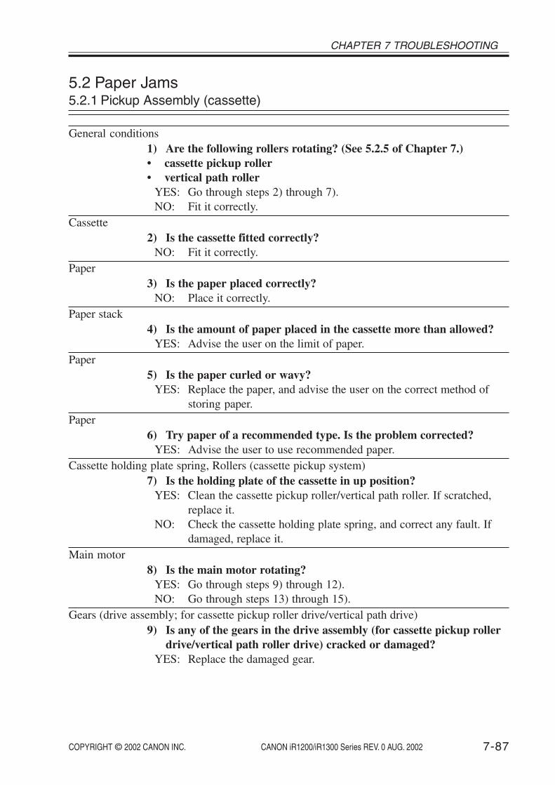
COPYRIGHT © 2002 CANON INC. 2000 2000 2000 2000 CANON iR1200/iR1300 Series REV. 0 AUG. 2002 7-87
CHAPTER 7 TROUBLESHOOTING
5.2 Paper Jams5.2.1 Pickup Assembly (cassette)
General conditions1) Are the following rollers rotating? (See 5.2.5 of Chapter 7.)• cassette pickup roller• vertical path roller
YES: Go through steps 2) through 7).NO: Fit it correctly.
Cassette2) Is the cassette fitted correctly?
NO: Fit it correctly.Paper
3) Is the paper placed correctly?NO: Place it correctly.
Paper stack4) Is the amount of paper placed in the cassette more than allowed?
YES: Advise the user on the limit of paper.Paper
5) Is the paper curled or wavy?YES: Replace the paper, and advise the user on the correct method of
storing paper.Paper
6) Try paper of a recommended type. Is the problem corrected?YES: Advise the user to use recommended paper.
Cassette holding plate spring, Rollers (cassette pickup system)7) Is the holding plate of the cassette in up position?
YES: Clean the cassette pickup roller/vertical path roller. If scratched,replace it.
NO: Check the cassette holding plate spring, and correct any fault. Ifdamaged, replace it.
Main motor8) Is the main motor rotating?
YES: Go through steps 9) through 12).NO: Go through steps 13) through 15).
Gears (drive assembly; for cassette pickup roller drive/vertical path drive)9) Is any of the gears in the drive assembly (for cassette pickup roller
drive/vertical path roller drive) cracked or damaged?YES: Replace the damaged gear.

COPYRIGHT © 2002 CANON INC. 2000 2000 2000 2000 CANON iR1200/iR1300 Series REV. 0 AUG. 2002
CHAPTER 7 TROUBLESHOOTING
7-88
Connector (if the cassette pickup roller is not rotating)10) Is the connection of the connectors on the image processor PCB
(J303, J307) and the DC controller PCB (J204) normal?NO: Correct the connection. If the flexible cable has a scratch, replace
it.Cassette pickup solenoid (SL2; if the cassette pickup roller is not rotating)
11) Try replacing the cassette pickup solenoid (SL2). Is the problemcorrected?
YES: End.DC controller PCB, Image processor PCB (if the cassette pickup roller is not rotating)
12) Try replacing the DC controller PCB. Is the problem corrected?YES: End.NO: Replace the image processor PCB.
Connector (main motor)13) Is the connection of the connector of the main motor unit and the
connector (J312) on the image processor PCB normal?NO: Correct the connection.
Main motor14) Try replacing the main motor. Is the problem corrected?
YES: End.DC controller PCB, Image processor PCB
15) Try replacing the DC controller PCB. Is the problem corrected?YES: End.NO: Replace the image processor PCB.

COPYRIGHT © 2002 CANON INC. 2000 2000 2000 2000 CANON iR1200/iR1300 Series REV. 0 AUG. 2002 7-89
CHAPTER 7 TROUBLESHOOTING
5.2.2 Pickup Assembly (manual feed tray)
General conditions1) Is the manual feed pickup roller rotating?
YES: Go through steps 2) to 6).NO: Go to step 7).
Paper2) Is the paper placed correctly?
NO: Place the paper correctly.Paper stack
3) Is the amount of paper placed in the manual feed tray more thanallowed?
YES: Advise the user on the amount of paper that may be placed.Paper
4) Is the paper curled or wavy?YES: Replace the paper, and advise the user on the correct method of
storing paper.Paper
5) Try paper of a recommended type. Is the problem corrected?YES: Advise the user to use recommended paper.
Paper guide plate ascent mechanism, Manual feed pickup roller6) Does the paper guide plate move up in conjunction with pickup op-
eration?YES: Clean the manual feed roller. If scratched, replace it.NO: Check to see if the spring used to push up the paper guide is
mounted correctly.Main motor
7) Is the main motor rotating?YES: Go through steps 8) through 11).NO: Go through steps 12) through 14).
Gear (in drive assembly; for manual feed pickup roller drive)8) Is any of the gears in the drive assembly (used to drive the manual
feed pickup roller) cracked or damaged?YES: Replace the faulty gear.
Connector9) Is the connection of the connectors on the image processor PCB
(J303, J308) and on the DC controller PCB (J204) normal?NO: Correct the connection. If the flexible cable has a scratch, replace
it.

COPYRIGHT © 2002 CANON INC. 2000 2000 2000 2000 CANON iR1200/iR1300 Series REV. 0 AUG. 2002
CHAPTER 7 TROUBLESHOOTING
7-90
Manual feed pickup solenoid (SL1)10) Replace the manual feed pickup solenoid (SL1). Is the problem cor-
rected?YES: End.
DC controller PCB, Image processor PCB11) Try replacing the DC controller PCB. Is the problem corrected?
YES: End.NO: Replace the image processor PCB.
Connector (main motor)12) Is the connection of the connector of the main motor unit and the
connector (J312) on the image processor PCB normal?NO: Correct the connection.
Main motor13) Try replacing the main motor. Is the problem corrected?
YES: End.DC controller PCB, Image processor PCB
14) Try replacing the DC controller PCB. Is the problem corrected?YES: End.NO: Replace the image processor PCB.

COPYRIGHT © 2002 CANON INC. 2000 2000 2000 2000 CANON iR1200/iR1300 Series REV. 0 AUG. 2002 7-91
CHAPTER 7 TROUBLESHOOTING
5.2.3 Feeding Assembly
General conditions1) Are the following components rotating normally? (See 5.2.5 of
Chapter 7.)• registration roller• gears in contact with photosensitive drum
YES: Go through steps 2) to 8).NO: Go to step 11).
Paper2) Is the paper curled or wavy?
YES: Replace the paper, and advise the user on the correct method ofstoring paper.
Paper3) Try paper of a recommended type. Is the problem corrected?
YES: Advise the user to user recommended paper.Feeding assembly
4) Is the surface of the following components normal?• registration roller• photosensitive drum• transfer charging roller
NO: Clean the soiled component. If scratched, replace it. If the photo-sensitive drum is scratched, replace the cartridge.
Registration roller locking mechanisms5) Is the registration roller locking spring normal?
NO: Replace the locking spring.Registration shutter mechanism
6) Is the registration shutter spring normal?NO: Replace the locking spring.
Paper path7) Is there dirt or foreign matter in the paper path?
YES: Clean the paper path. If any, remove the foreign matter.General conditions
8) Is LGL paper placed in the cassette?YES: Go through steps 9) and 10).NO: Check the jam sensor. (See 4.2.9 of Chapter 7.)
Side guide plate9) Is the side guide plate of the cassette mounted correctly?
NO: Mount the side guide plate correctly. If scratched, replace it.

COPYRIGHT © 2002 CANON INC. 2000 2000 2000 2000 CANON iR1200/iR1300 Series REV. 0 AUG. 2002
CHAPTER 7 TROUBLESHOOTING
7-92
Sensor flag10) Is the flag for the LGL paper sensor (PS101) damaged or dis-
placed?YES: Correct it. If damaged, replace it.NO: Replace the DC controller PCB.
Gear (in drive assembly; for registration roller, photosensitive drum, transfer charging rollerdrive)
11) Is any of the gears in the drive assembly cracked or damaged (usedto drive the registration roller, photosensitive drum, transfer charg-ing roller)?
YES: Replace the damaged gear. If the gear on the photosensitive drumside is damaged, replace the cartridge.)

COPYRIGHT © 2002 CANON INC. 2000 2000 2000 2000 CANON iR1200/iR1300 Series REV. 0 AUG. 2002 7-93
CHAPTER 7 TROUBLESHOOTING
5.2.4 Fixing Delivery Assembly
General conditions1) Is the delivery roller rotating normally?
YES: Go through steps 2) to 7).NO: Go to step 8).
Paper2) Is the paper curled or wavy?
YES: Replace the paper, and advise the user on the correct method ofstoring paper.
Paper3) Try paper of a recommended type. Is the problem corrected?
YES: Advise the user to use recommended paper.Fixing pressure roller
4) Execute fixing pressure roller cleaning. Is the problem corrected?(See 4.1.1 of Chapter 6.)
YES: Advise the user to clean the component on a periodical basis.Fixing inlet guide
5) Is the fixing inlet guide soiled, or is there foreign matter?YES: Clean it. If there is any foreign matter, remove it.
Roller (fixing delivery system)6) Is the surface of the following rollers normal?• fixing pressure roller• delivery roller
NO: Clean the soiled component. If scratched, replace it.Delivery sensor
7) Check the delivery sensor. Is the problem corrected?NO: Replace the delivery sensor.
Gear (in drive assembly; for fixing plessure roller, delivery roller drive)8) Is any of the gears of the drive assembly (used to drive the fixing
pressure roller, delivery roller) cracked or damaged?YES: Replace the damaged gear.

COPYRIGHT © 2002 CANON INC. 2000 2000 2000 2000 CANON iR1200/iR1300 Series REV. 0 AUG. 2002
CHAPTER 7 TROUBLESHOOTING
7-94
5.2.5 Checking the Rotation of the Rollers and GearsIf a jam occurs, go through the following to find out whether the rollers are rotating nor-
mally:
5.2.5.1 Checking the Rotation of the Cassette Pickup Roller and the Vertical PathRoller
1) Check to be sure that the machine is in standby state.2) Open the right door.3) Press the Start key.4) Check the rotation of the roller through the right door area of the machine.
5.2.5.2 Checking the Rotation of the Registration Roller and the Gear for the Photo-sensitive Drum
1) Check to be sure that the machine is in standby state.2) Slide the reader unit.3) Open the copyboard cover, and remove the reader cover.4) Open the cartridge cover.5) Remove the cartridge.6) While pressing the reader unit slide detecting switch (SW1) and toner bottle sensor
(PS11) with a screwdriver, press the Start key.7) Check the rotation of the roller/gear through the right side area of the machine.
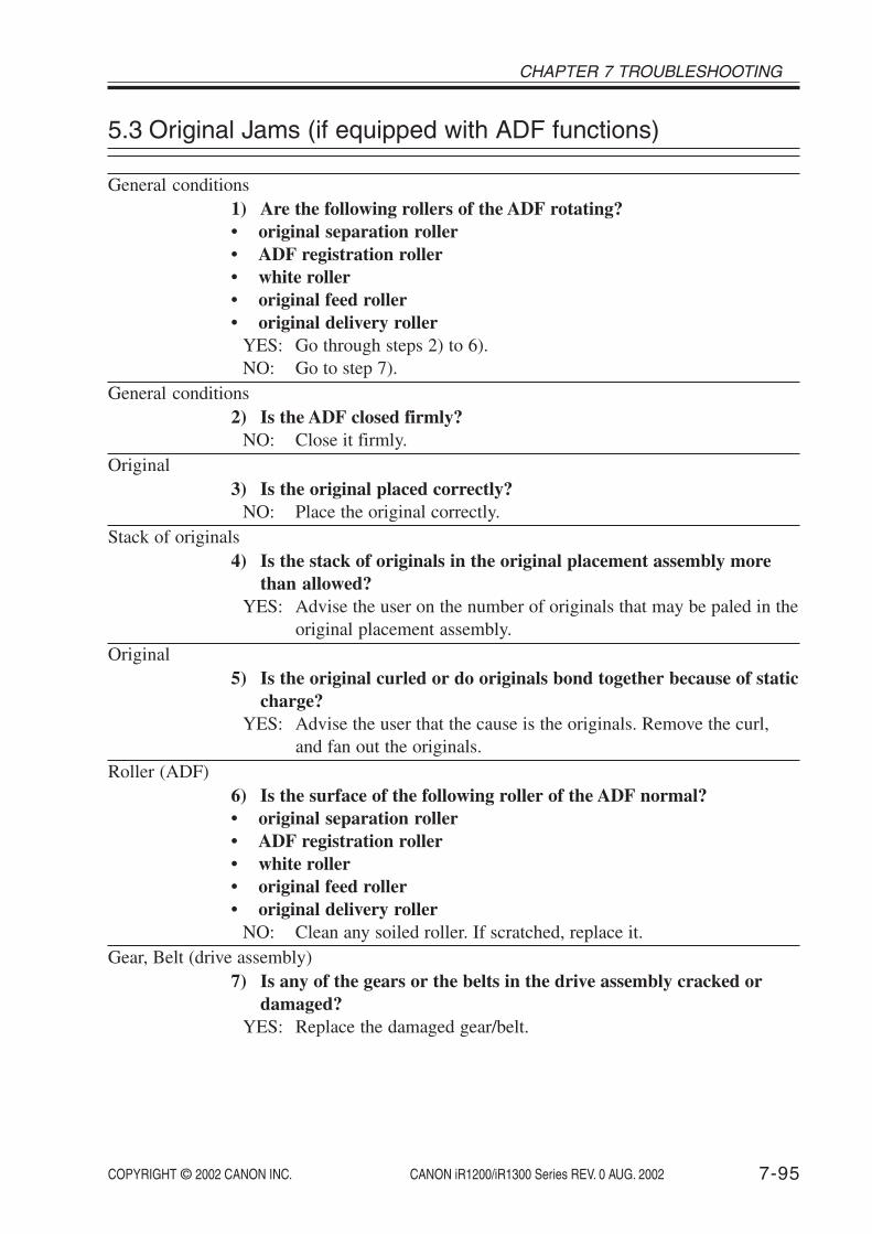
COPYRIGHT © 2002 CANON INC. 2000 2000 2000 2000 CANON iR1200/iR1300 Series REV. 0 AUG. 2002 7-95
CHAPTER 7 TROUBLESHOOTING
5.3 Original Jams (if equipped with ADF functions)
General conditions1) Are the following rollers of the ADF rotating?• original separation roller• ADF registration roller• white roller• original feed roller• original delivery roller
YES: Go through steps 2) to 6).NO: Go to step 7).
General conditions2) Is the ADF closed firmly?
NO: Close it firmly.Original
3) Is the original placed correctly?NO: Place the original correctly.
Stack of originals4) Is the stack of originals in the original placement assembly more
than allowed?YES: Advise the user on the number of originals that may be paled in the
original placement assembly.Original
5) Is the original curled or do originals bond together because of staticcharge?
YES: Advise the user that the cause is the originals. Remove the curl,and fan out the originals.
Roller (ADF)6) Is the surface of the following roller of the ADF normal?• original separation roller• ADF registration roller• white roller• original feed roller• original delivery roller
NO: Clean any soiled roller. If scratched, replace it.Gear, Belt (drive assembly)
7) Is any of the gears or the belts in the drive assembly cracked ordamaged?
YES: Replace the damaged gear/belt.

COPYRIGHT © 2002 CANON INC. 2000 2000 2000 2000 CANON iR1200/iR1300 Series REV. 0 AUG. 2002
CHAPTER 7 TROUBLESHOOTING
7-96
5.4 Feeding Faults5.4.1 Double Feeding
Paper1) Is the paper placed correctly?
NO: Place the paper correctly.Stack of paper
2) Is the amount of paper in the cassette/manual feed tray more thanallowed?
YES: Advise the user on the amount of paper that may be placed.Paper
3) Is the paper curled or wavy?YES: Replace the paper, and advise the user on the correct method of
storing paper.Paper
4) Try paper of a recommended type. Is the problem corrected?YES: Advise the user to use recommended paper.
Claws (cassette)5) Is the claw of the cassette deformed?
YES: Correct the deformation. If the deformation cannot be corrected,replace the cassette.
Separation pad, Separation pad pressure spring (manual feed tray)6) Is the surface of the separation pad of the manual feed tray nor-
mal?YES: Replace the pressure spring of the separation pad.NO: Clean it. If worn, replace it.

COPYRIGHT © 2002 CANON INC. 2000 2000 2000 2000 CANON iR1200/iR1300 Series REV. 0 AUG. 2002 7-97
CHAPTER 7 TROUBLESHOOTING
5.4.2 Wrinkles
Pickup assembly1) Turn off the power while the paper is being moved. At this time, is
the paper wrinkled or moving askew?YES: Check the rollers of the pickup assembly and the registration roller
and the registration shutter. If damaged, replace the components.Paper
2) Is the paper placed correctly?NO: Place the paper correctly.
Paper3) Is the paper curled or wavy?
YES: Replace the paper, and advise the user on the correct method ofstoring paper.
Paper4) Try paper of a recommended type. Is the problem corrected?
YES: Advise the user to use recommended paper.Fixing assembly inlet guide
5) Is the fixing inlet guide soiled, or is there foreign matter?YES: Clean it. If there is any foreign matter, remove it.NO: Replace the fixing assembly.

COPYRIGHT © 2002 CANON INC. 2000 2000 2000 2000 CANON iR1200/iR1300 Series REV. 0 AUG. 2002
CHAPTER 7 TROUBLESHOOTING
7-98
5.5 Faulty Feeding of Originals (if equipped with ADF func-tions)
5.5.1 Double Feeding
Original1) Is the original placed correctly?
NO: Place the original correctly.Stack of originals
2) Is the stack of originals placed in the original placement assemblymore than allowed?
YES: Advise the user on the number of originals that may be placed.Original
3) Is the original curled or do originals bond together because of staticcharge?
YES: Advise the user that the cause is the originals. Remove the curl, orfan out the originals.
Original separation pad, Pressure spring (original separation pad)4) Is the surface of the original separation pad normal?
YES: Replace the pressure spring of the original separation pad.NO: Clean it. If worn or faulty, replace it.
5.5.2 Skew
Slide guide1) Is the slide guide fitted correctly to suit the width of the original?
NO: Fit it correctly.Original
2) Are originals of different widths placed together?YES: Make sure that all originals are of the same width when placed on
the original placement area.Skew correction
3) Is the skew correction value appropriate?NO: Execute skew correction. (See 1.3.3.1 of Chapter 7.)If you have corrected the skew, check to be sure the settings of all otheradjustment items for the ADF are as indicated in specs.
Original separation pad, Roller (separation roller unit)4) Clean the original separation pad and the rollers of the separation
roller unit. Is the problem corrected?YES: End.NO: Replace the original separation pad or the rollers of the separation
roller unit.

COPYRIGHT © 2002 CANON INC. 2000 2000 2000 2000 CANON iR1200/iR1300 Series REV. 0 AUG. 2002 7-99
CHAPTER 7 TROUBLESHOOTING
6 Arrangement of the Electrical Parts
6.1 Checking the PhotointerruptersUse ‘SENSOR’ under ‘TEST MODE’ in service mode to check photointerrupters as fol-
lows:1) Press the Additional Functions key and the # key to start service mode.2) Press the Left/Right Arrow key so that ‘TEST MODE’ is indicated.3) Press ‘6’ on the keypad so that ‘6: FACULTY TEST’ is indicated.4) Press ‘3’ on the keypad to start sensor check mode, in which the following screen ap-
pears:
6-3:SENSOR[1] - - - [4]
F07-601-01
5) When the screen shown in F07-601-01 is displayed, press ‘1’, ‘2’, ‘3’, or ‘4’ to bring up theState screen of a specific sensor. For instance, when ‘1’ is pressed, the following will be true:
DS of DES of DDS of CRG on DCVS on
Sensor name
Present stateof the sensor
Present stateof the sensor
Sensor name
‘DS of’ indicates that the original sensor (DS) of the ADF is OFF.
F07-601-02
6) Move the flag of the sensor to see that the indication alternates between ‘of’ and ‘on’ toindicate that the sensor is going OFF and ON.On the next page, the screens that appear when ‘1’ through ‘4’ are pressed are shown to-gether with the sensor names and the sensor states when the machine is in standby state.

COPYRIGHT © 2002 CANON INC. 2000 2000 2000 2000 CANON iR1200/iR1300 Series REV. 0 AUG. 2002
CHAPTER 7 TROUBLESHOOTING
7-100
6-3:SENOR[1] - - - [4]
DS of DES of DDS ofCRG on DCVS on
HPS on BCVS ofTBS on WTS of
CT1 on A4
MLT on A4 TN on JAM of
Press '1' on the keypad.
DS: original sensor*1 (PS6); 'on' if present, 'of' if absent.DES: registration sensor*1 (PS7); 'on' if present, 'of' if absent.DDS: original delivery sensor*1(PS8);'on' if present, 'of' if absent.CRG: not usedDCVS: Reader unit slide detecting switch (SW1) and toner supply cover open/closed detecting switch (SW2):
'on' reader unit in position and toner supply cover closed'of' reader unit not in position or toner supply cover open
*1: indicates the state of a specific sensor of the ADF.
Press '2' on the keypad.
HPS: contact sensor home position sensor (PS1): 'on' contact sensor in home position, 'of' contact sensor not in home position.
BCVS: ADF (copyboard cover) open/close sensor (PS2); 'on' cover open, 'of' cover closed.TBS: toner bottle sensor (PS11):
'on' toner bottle fitted,'of' toner bottle not fitted (cartridge not fitted).
WTS: waste toner full sensor (PS12):'on' if present, 'of' if absent.
Press '3' on the keypad.
CT1: cassette paper sensor (P103); 'on' paper present, 'of' paper absent.
Press '4' on the keypad.
MLT:manual feed tray paper sensor (PS4); 'on' paper present, 'of' paper absent.TN: not used.JAM: not used.
F07-601-03
The paper leading edge sensor (PS102), LGL paper sensor (PS101), anddelivery sensor (PS3) cannot be checked by running a sensor test.

COPYRIGHT © 2002 CANON INC. 2000 2000 2000 2000 CANON iR1200/iR1300 Series REV. 0 AUG. 2002 7-101
CHAPTER 7 TROUBLESHOOTING
6.2 Arrangement and Functions of Electrical Components6.2.1 Solenoids, Motors, Fans6.2.1.1 Body
M4
FM1
M2
SL1
SL2
M1
F07-602-01

COPYRIGHT © 2002 CANON INC. 2000 2000 2000 2000 CANON iR1200/iR1300 Series REV. 0 AUG. 2002
CHAPTER 7 TROUBLESHOOTING
7-102
6.2.1.2 ADF (if equipped with ADF functions)
M3
F07-602-02
Solenoids, Motors, and Fans
T07-602-01
Symbol
SL
M
Name
Solenoid
Motor
Fan
Notation
SL1SL2M1M2M3
M4FM1
Description
manual feed pickup roller drivecassette pickup roller drivemain motorreader motorADF motor (if equipped with ADFfunctions)laser scanner motorfan

COPYRIGHT © 2002 CANON INC. 2000 2000 2000 2000 CANON iR1200/iR1300 Series REV. 0 AUG. 2002 7-103
CHAPTER 7 TROUBLESHOOTING
6.2.2 Sensors6.2.2.1 Body
PS1
PS2
PS4
PS3
PS101
PS11PS103
PS102
PS10
F07-602-03

COPYRIGHT © 2002 CANON INC. 2000 2000 2000 2000 CANON iR1200/iR1300 Series REV. 0 AUG. 2002
CHAPTER 7 TROUBLESHOOTING
7-104
6.2.2.2 ADF (if equipped with ADF functions)
PS7PS6
PS8
F07-602-04
Name
Photointerrupters
Notation
PS1
PS2
PS3PS4PS6
PS7
PS8
PS10PS11PS101PS102PS103
Description
constant sensor home position de-tectionADF (copyboard cover) open/closedetectiondelivery detectionmanual feed tray paper detectionoriginal detection (if equipped withADF functions)ADF registration paper detection(if equipped with ADF functions)original delivery detection (ifequipped with ADF functions)waste toner casing full detectiontoner bottle set detectionLGL paper detectionpaper leading edge detectioncassette paper detection
Sensors
Symbol
T07-602-02

COPYRIGHT © 2002 CANON INC. 2000 2000 2000 2000 CANON iR1200/iR1300 Series REV. 0 AUG. 2002 7-105
CHAPTER 7 TROUBLESHOOTING
6.2.3 Others
FU2
H1
TH1SP1
TH2
SW1
SW2
HS
F07-602-05

COPYRIGHT © 2002 CANON INC. 2000 2000 2000 2000 CANON iR1200/iR1300 Series REV. 0 AUG. 2002
CHAPTER 7 TROUBLESHOOTING
7-106
Symbol Name
Switch
Humiditysensor
Heater
Thermistor
Thermal fuse
Speaker
Notation
SW1SW2
HS
H1
TH1
TH2
FU2
SP1
Description
reader unit slide detectingtoner supply cover open/close detecting
humidity check
fixing heater
fixing main thermistor (fixing assembly cen-ter temperature detection)fixing sub thermistor (fixing assembly endtemperature detection)
Fixing heater error temperature detection
speaker*1
T07-602-03
*1: If equipped with fax functions.
Others

COPYRIGHT © 2002 CANON INC. 2000 2000 2000 2000 CANON iR1200/iR1300 Series REV. 0 AUG. 2002 7-107
CHAPTER 7 TROUBLESHOOTING
6.2.4 PCBs
[1]
[7]
[3]
[5]
[6]
[2]
[4]
[8]
[9]
F07-602-06

COPYRIGHT © 2002 CANON INC. 2000 2000 2000 2000 CANON iR1200/iR1300 Series REV. 0 AUG. 2002
CHAPTER 7 TROUBLESHOOTING
7-108
[12]
[11]
[13]
[10]
F07-602-07
PCBs
Ref.
12345
6789
10111213
Name
Image processor PCBDC controller PCBAnalog processor PCBControl panel PCBSensor PCB
Power supply PCBPrinter controller PCBNCU PCB*1
Modular jack PCB*1
Laser scanner motor driverLaser driver BD PCBMain motor driverSensor relay PCB
Description
image processing controlDC load controlcontact sensor drive, analog image processingcontrol panel controlADF (copyboard cover) open/close detection,contact sensor home position detectionlow-voltage power supply controlcomputer combination controlfax communication controltelephone line connectionlaser scanner motor drive
laser drive, laser beam detectionmain motor driveRelay between the humidity sensor/the tonerbottle sensor and the DC controller PCB
T07-602-04
*1: If equipped with fax functions.

COPYRIGHT © 2002 CANON INC. 2000 2000 2000 2000 CANON iR1200/iR1300 Series REV. 0 AUG. 2002 7-109
CHAPTER 7 TROUBLESHOOTING
6.3 Variable Resistors, Light Emitting Diodes (LED), andCheck Pins by PCB
Of the VRs, LEDs, and check pins used in the machine, those needed when servicing inthe field are discussed:
1. Some LEDs emit dim light even when OFF; this is a normal condition,and must be kept in mind.
2. VRs that may be used in the field: VRs that must not be used in the field:
Do not touch the VRs and check pins not found in the lists herein; they areexclusively for the factory, and require special tools and high accuracy.
6.3.1 Image Processor PCB
J309J310 J311*1 J312 J314 J316J317
J318
VR900
J81*2
J301J302J303J307
JP1BAT1
BAT2
J11
J308
J315
J321*2
J320*2
J304
J352
J351
F07-603-01
JP1: jumper plug for power used by battery to back up memory (control data; user data, servicemode data).
BAT1: battery used to back up memory (SRAM; control data; service mode data, user mode data).BAT2: battery used to back up memory (SDRAM; fax images)
*1: If equipped with ADF functions.*2: If equipped with fax functions.

COPYRIGHT © 2002 CANON INC. 2000 2000 2000 2000 CANON iR1200/iR1300 Series REV. 0 AUG. 2002
CHAPTER 7 TROUBLESHOOTING
7-110
6.3.2 DC Controller PCB
VR102VR101
PS101J203 J202
J201 J204
J210
J208
PS103
PS102J209
J207
J205
J206
J252 J251
F07-603-02
VR101: for factory adjustmentVR102: for factory adjustment

COPYRIGHT © 2002 CANON INC. 2000 2000 2000 2000 CANON iR1200/iR1300 Series REV. 0 AUG. 2002
APPENDIX


A-1
APPENDIX
COPYRIGHT © 2002 CANON INC. 2000 2000 2000 2000 CANON iR1200/iR1300 Series REV. 0 AUG. 2002
1 General Timing Chart
Start key ONPower ON
Laser scanner motorCassettepickup solenoid
Paper leadingedge sensor
Delivery sensor
Primary chargingbias (AC)Primary chargingbias (DC)
Contactsensor LED
Developingbias (DC)
Developingbias (AC)
Laser diode
Transfer bias
Fixing heater
Contact sensorhome position sensor
Reader motor
Main motor
STBYWAIT INTR PRINT LSTR STBY
*1 : Varies depending on the density setting and the humidity.*2 : Cleaning bias control.*3 : ATVC control.*4 : Sheet-to-sheet bias control.*5 : Temperature control by paper type.*6 : Varies depending on the humidity.
*1
*2
*1
ReverseForward
*2
(book mode, A4, 2 copies, Direct, cassette)
*3 *4 *6 *6*4 *4
*5

APPENDIX
A-2 COPYRIGHT © 2002 CANON INC. 2000 2000 2000 2000 CANON iR1200/iR1300 Series REV. 0 AUG. 2002
Start key ONPower ON
Laserscanner motor
Cassettepickup solenoid
Paper leadingedge sensor
Delivery sensor
Primary chargingbias (AC)
Primary chargingbias (DC)
Contactsensor LED
Developingbias (DC)
Developingbias (AC)
Laser diode
Transfer bias
Fixing heater
Contact sensorhome position sensor
Reader motor
Main motor
STBYWAIT INTR PRINT LSTR STBY
*1 : Varies depending on the density setting and the humidity.*2 : Cleaning bias control.*3 : ATVC control.*4 : Sheet-to-sheet bias control.*5 : Temperature control by paper type.*6 : Varies depending on the humidity.
*1
*2
*1
ReverseForward
*2
Originaldelivery sensor
Registrationsensor
Original sensor
ADF motor
(ADF, A4 original, A4 paper, 2 copies, Direct, cassette)
CCW rotation CW rotation
*3 *4 *4
*5
*4 *6 *6

A-3
APPENDIX
COPYRIGHT © 2002 CANON INC. 2000 2000 2000 2000 CANON iR1200/iR1300 Series REV. 0 AUG. 2002
2 General Circuit Diagram
NCU PCB*2
Power supplyPCB DC controller PCB
Sensor relay PCB
Printer controllerPCB
Fixing assembly
Image processor PCB
Modularjack
PCB*2
Cartridge
Control panel PCB
LCD
Control panel
Membrane
Analog processor PCB
Contact sensor Laser driver/BD PCB
Reader unitslide detecting
switch
Toner supplycover switch
SensorPCB
Originalsensor
Humidity sensorToner bottlesensor
Waste tonerfull sensor
Contact sensorhome position
sensorFan
Mainmotor driver
Scanner motor
Copyboardcover open/closesensor
Registrationsensor
ADF motorOriginaldeliverysensor
Reader motor
*1: If equipped ADF functions.*2: If equipped fax functions.*3: Specific country / region models only.
6 5 4 3 2 1
1 2 3 4 5 6 1 2 3 4 5 6 7 8 9 10 11 12 13 14 15 16 17 18 19 20 21 22 23 1 2 3 4 5 6 7 8 9 10 11 12 13 14 15 16 17 18 19 20 21 22 23 24 25 26 27 28 29 30
1920212223 18 17 16 15 14 13 12 11 10 9 8 7 6 5 4 3 2 1
12
12
1 2 3 4 5 6 7 81 2 3 4
1 2 3 4 5 6 7 81 2 3 4
12
34
56
78
910
1 2 3 4
1 2 31 2 3
1 2 3
1 2 3
12
34
56
78
9
12
3
1 2 3
12
3
1 2 3
1 2 3
1 2 3
1 2 3
1 2
1 2
SL
SL
21
21
32
1
32
1
32
1
J308
J314
12
34
12
34
J911 J8
12
34
56
12
34
56
J912 J7
J907 J10
J2 J1 J6
J321J81
12
34
5
12
34
5
J320
J4
J1051
PS3
TH2 TH1
H1
TP1
J1071M
J1071F
TP
MT5MT6
J102
J103 J104
J301 J302
J108
J106
J206
PS101 PS102 PS103
J209
J205
J204J201
J303 J318
J701
J304
J203
J202
J207
J208
J107J105J109
J7J18
P2
SOLD1SOLD2
J309
SL1
PS4
SL2
J307
4 3 2 1
4 3 2 1
109
87
65
43
21
3 2 1
3 2 1
3 2 1
3 2 1
3 2 1
3 2 13 2 1
98
76
54
32
1
192021222324252627282930 18 17 16 15 14 13 12 11 10 9 8 7 6 5 4 3 2 1
11 10 9 8 7 6 5 4 3 2 1
1 2 3 4 5 6 7 8 9 10 11 12 13 14 15 161 2 3 4 5 6 7 8 9 10 11 12 13 14
12
1 2 3 4 5 6 7 8 9 10 11
J401
J402
J404
J403
J315
12
1 2 1 2
12
12
12
InletPower cord
Speaker*2
LGLpaper sensor
Paper leadingedge sensor
Cassettepaper sensor
Transfer bias
Primarycharging
bias
Developingbias
Tonerdensity
detection
Deliverysensor
Fixing film bias
Subthermistor
Mainthermistor Fixing
heater
SP1
Manual feed tray pickup solenoid
Cassette pickup solenoid
21
1 2 3J3112
PS6
1 2 3
1 2 3J3112
J3111DH
J311 J310 J317 J312 J316
J801
J3111L
PS7
PS11
PS10
HS
1 2 3
1 2 3J3112
J3102L
J3102DH
PS8
1 2 3
J6530J6521
J652
J651
J251J252
J653
J2521
J2520HJ2520D
J2520L
PS2 PS1
M3
M
6 5 4 3 2 16 5 4 3 2 1
M4
SW1
M
M2M
1 2 3 4 5 6
15 14 13 12 11 10 9 8 7 6 5 4 3 2 1 1 2 3 4 5 6 7 8 9 10 11 12 13 14 15 16 17 18 19 20 21 22 23 24 25 26 27 28 29 30 31 32
1920 18 17 16 15 14 13 12 11 10 9 8 7 6 5 4 3 2 1212223242526272829303132
6 5 4 3 2 1
M
6 5 4 3 2 1
15 14 13 12 11 10 9 8 7 6 5 4 3 2 14 3 2 1
1 2 3 4 5 6 7 8 9 10 11 12 13 14 151 2 3 4J502
J601
J503
J504
J501
12
43
12
43
4 3 2 1
1 2 3 4
1 2 3 4
FM1
1 2 310 9 8 7 6 5 4 3 2 1
1 2 3 4 5 6 7 8 9 10
M1
J3122
J3121LJ3121HJ3121D
ADF*1 Reader unit Laser scanner unitScanner
motor driver
3 2 1
3 2 1
1 2 3
1 2 3
1 2 3
4 3 2 1
1 2 3 4
1 2 3 4
1 2 3 4
10 9 8 7 6 5 4 3 2 1 3 2 1
23 1
Manual feed tray paper sensor
J308
1
J314
0M
J314
0F
1 2 3 4 5 6 7 8 9 10 11 12 13 14
14 13 12 11 10 9 8 7 6 5 4 3 2 1
1 2 3 4 5 6 7 8 9 10 11 12 13 14 15 16 17 18
18 17 16 15 14 13 12 11 10 9 8 7 6 5 4 3 2 1
USB PortParallel Port
*3 *3
*3
*3
*3
*3
*3
*3
SW2
23 1
12
3
12
3
MPSENSGND
+24RMP_SL_DRV
+24RCST_SL_DRV
MPSDRV
RX
TX
AN
OU
T+
12V
N.C
.G
ND
GN
DR
GV
3+
3.3V
SR
DP
RD
HR
DC
MLD
DC
DN
.C.
+3.
3VG
ND
+24
VG
ND
GN
D+
12V
GN
DR
GV
5G
ND
+5V
GN
D
XPCI SLEEPFSRDRYRLYDRYPOSNSPOSDRYGND
GNDGND
GND
GND
+24V+24V
+5R
+3.3R
+24
R
+24
R
FS
R_E
RR
_DE
TR
L_D
RV
_IP
ES
S_M
OD
E_C
HK
SLE
EP
MP
SN
SM
PS
NS
_DR
V
GN
DS
VC
HG
DE
CA
CC
GN
DC
NT
RL1
CN
TR
L0B
DI
GN
D
GN
DR
ES
ET
0
BD
OS
CLK
SC
GN
DF
LOC
KFA
NO
NM
ON
MP
_SL_
DR
VC
ST
_SL_
DR
VX
PC
T
GN
D
GN
D
GN
D
GN
D
GN
D
GN
D
RE
SE
T_C
C
MF
PS
LP_C
CP
DLS
LP_C
C
FB
DF
SC
FT
CLK
FV
DO
-F
VD
O+
+5V
+5V
+3.
3U+
3.3U
GNDFSRTH
SUBTH
RG
V3
CI1
CI2
CI0
RH
OO
K1
N.C
.N
.C.
N.C
.B
IT0
BIT
1B
IT2
GN
D
NZ
AS
T
CIS
T1
C2
C1
NO
RR
RD
DC
LIM
DC
SE
LIP
SE
L3IP
SE
L2IP
SE
L1O
UT
CIS
T2
GN
D
GN
D
GN
DS
UB
TH
MA
INT
H
FS
R(L
)
FS
R(N
)
+3.
3R
BO
TT
LE
BO
TT
LE
+3.
3R
+3.
3RH
UM
SN
S
GN
D
GN
D
GN
D
+3.
3RG
ND
TN
R_F
ULL
HY
UM
IDT
Y_S
PO
SD
RY
PO
SE
NS
VHGND
NH
NH
W
RT21T22
W
RT1
T1T2
T2
L1
L1L2
L2
-SP
+S
PE
SS
_LE
DE
SS
KE
YP
NLC
KG
ND
PN
LTX
PN
LRS
TP
NLR
XR
GV
5+
5V
KO
UT
0K
OU
T1
KO
UT
2K
OU
T3
KO
UT
4K
OU
T5
KIN
0K
IN1
KIN
2K
IN3
KIN
4K
IN5
KIN
6K
IN7
GN
DE
SS
LED
V0
RG
V5
GN
DD
B7
DB
6D
B5
DB
4D
B3
DB
2D
B1
DB
0E R
/ W
RS
+SP-SP
B BC
ON
B A AC
ON
DF
-DO
CU
-DR
Y
DF
-RE
G-D
RY
DF
-EX
P-D
RY
GN
D
GN
D
GN
D
A
B BA AB BA AD
F-D
OC
U
DF
-RE
G
DF
-EX
P
BO
OK
CO
BE
RS
EN
SR
DH
PS
EN
SLE
DG
LED
RLE
DB
DG
ND
+8V
DG
ND
DG
ND
RS
_CLK
M_C
LKT
R_C
LKC
L_C
LKS
H_C
LKA
D_C
LK+
3.3V
VD
9 V
D8
VD
7 V
D6
VD
5 V
D4
VD
3 V
D2
VD
1 V
D0
SI_
OU
T
SI_
EN
S
I_IN
S
I_C
LK
AD
_RS
T
+8V
+5V
GN
DBO
OKCO
VERS
ENS
+5V
+5V
GN
D
+5V DG
ND
DG
ND
DG
ND
AG
ND
AG
ND
OS
1
OS
2
RS
_CLK
M_C
LKT
R_C
LK+
5VD
IG
LED
GLE
DR
LED
B+
8 V
RG
V5
RG
V3
GN
D
GN
D
GN
D
CN
TR
L0
+24
V
+24V
+24
R
CN
TR
L1
VD
OV
DO
BD
I
GN
D
GN
D
GN
D
FAN
ON
FLO
CK
+24
R
SV
CH
G
MO
N
AC
CD
EC

APPENDIX
A-4 COPYRIGHT © 2002 CANON INC. 2000 2000 2000 2000 CANON iR1200/iR1300 Series REV. 0 AUG. 2002
Blank page

A-5
APPENDIX
COPYRIGHT © 2002 CANON INC. 2000 2000 2000 2000 CANON iR1200/iR1300 Series REV. 0 AUG. 2002
3 List of Special Tools
The following tools are required in addition to the standard set of tools when servicing themachine:
No.
1
2
Tool name
Digital multimeter
NA-3 Test Sheet
Tool No.
FY9-2002
FY9-9196
Shape Rank*
A
A
*Rank:A: Every service person is expected to carry one.
Remarks
For making electricalchecks.
For adjusting/checkingimages.

APPENDIX
A-6 COPYRIGHT © 2002 CANON INC. 2000 2000 2000 2000 CANON iR1200/iR1300 Series REV. 0 AUG. 2002
4 List of Solvents and Oils
No.
1
2
3
Name
Alcohol
Lube,MOLYKOTEEM-50L,Grease
Electricitygrease (IF-20)
Use
Cleaning: e.g., glass,plastic, rubber; ex-ternal covers.
Lubricating; e.g.contact sensor driverail, drive assembly,hinge of the manualfeed tray, ADF deliv-ery roller and pickup shaft of the ADF.
Lubricating; e.g.connection of thevertical path rollerand the gear, con-nection of the deliv-ery roller and bush-ing.
Composition
Fluoride-familyhydrocarbon, alco-hol, surface activat-ing agent, water.
Polyalphaolefinoil,lithium soap,polybutene
–
Remarks
• Do not bring near fire.• Procure locally.• IPA (isopropyl alcohol) may be
substituted.
• Tool No. HY9-0007
• Tool No. CK-8006

Prepared by
Office Imaging Products Quality Assurance Center
CANON INC.
REVISION 0 (AUG. 2002) (30359/10653)
5-1, Hakusan 7-chome, Toride-shi, Ibaraki 302-8501 Japan
COPYRIGHT © 2002 CANON INC. 2000 2000 2000 2000 CANON iR1200/iR1300 Series REV. 0 AUG. 2002