Embed Size (px)
Citation preview
7/27/2019 IRC 34-1970 Road in Waterlogged Areas
http://slidepdf.com/reader/full/irc-34-1970-road-in-waterlogged-areas 1/8
IRC 1 34-1970
. .
RECO.MMENDATIONSFOR
ROAD ~ O N S T R U C T I O N- ~ .
WATEaLOGGED AREAS
THE INDIAN ROADS CONGRESS .
1996
7/27/2019 IRC 34-1970 Road in Waterlogged Areas
http://slidepdf.com/reader/full/irc-34-1970-road-in-waterlogged-areas 2/8
IRC : 34-1970
RECOMMENDATIONSFOR
ROAD CONSTRUCTIONIN
WATERLOGGED AREAS
Published by
THE INDIAN ROADS CONGERSS
Jamnagar House, Shabjaban Road,
New Delbi-110011
1996
Price Rs. 24.00
(Plus Packing & Postage)
7/27/2019 IRC 34-1970 Road in Waterlogged Areas
http://slidepdf.com/reader/full/irc-34-1970-road-in-waterlogged-areas 3/8
IR C : 34-1970
First Published
Reprinted
Reprinted
Reprinted
January, 1970
May, 1974May, 1980
August, 1996
[Rights of Publication and of Translation are reserved]
Printed at Sagar Printers and Publishers, New Delhi-110003
(1000 copies)
IRC: 34-1970
RECOMMENDATIONS FOR ROAD CONSTRUCTIONIN WATERLOGGED AREAS
1. INTRODUCTION
A Panel Discussion* on the subject of construction of roads inwaterlogged areas was held during the Hyderabad session of theIndian Roads Congress in January 1959. As a result of this discussion,the Soil Resea rch Commitee (personnel given below) took· uponitself the task of framing recommendations for road construction in
these areas:B.D Mathur
Dr. H.L. Uppal
Convenor
Member-Secretary
MEMBERS
N. Amanullah
K. Basanna
Lt. Col. Harish Chandra
S.N. Gupta
Dr. R.K. Katti
Kewal Krishan
Mahabir Prasad
H.C. Malhotra
M.R. Malya
J.S. Marya
Prof. S.R. Mehra
·H.V. Mirchandani
A. Muthukumaraswamy
A. R. Satyanarayana Ra o
S.N; Sinha
J.M. Trehan
Dr. I.S. Uppal
Director General (Road Development) &Addl. Secy. to the Government of India.
(Ex-Officio)
The recomendations drafted by the Committee were subsequently reviewed by the Specifications and Standards Committee (personnel given on inside front cover) and after approval of the Councilat their 72nd meetjng held on the 4th October, 1969 are now sugges
ted for general adoption in the country.
2. SCOPE
The recommendations deal with the problem of road construction in waterlogged areas, including those subject in addition toflooding andjor infested with detrimental salts like the sulphates andcarbonates. The recommendations relate both to the construction ofnew roads and to the remedial measures to be adopted in the caseof existing construction s.
*The background note for the Panel Discussion is published in the Journalof the Indian Roads Congress, Volume XXIII-part 2 and discussion in th eVolume XXIII-part 4. ·
1
7/27/2019 IRC 34-1970 Road in Waterlogged Areas
http://slidepdf.com/reader/full/irc-34-1970-road-in-waterlogged-areas 4/8
IRC : 34-1970
For the purpose of these recommendations, w a t e ~ l o g g e d a r ~ a sare considered to be those where the level of subsOil or standmgwater is such that for prolonged periods the subgrade immediatelybelow the pavement· is well within the capillary fringe of the water-table, i.e., within agout 1.5 metres. ·
3. TH E PROBLEM
3.1. Due to Waterlogging·
As a result of migration ofwater by capillarity from the highwater-table the soil immediately below the pavement gets more and
more wet this leads to a gradual loss in its bearing value.3.2. Due to Flooding
Where flooding for continuously long periods also takes placeside by side with waterloggfng, the progressive deformat ion of thesubgrade, as well as of the pavement,· is accentuated by ingress ofwater from the top of the wearing ·surface comprising usually of athin bituminous trea tment. The already inadequate waterproofnessof the surface is impaired further by stripping of the binder due toprolonged contact with water. Infiltration of o o d . waters throughthe shoulders is another fac tor aggravating the sttuatwn.
3. 3. . Due to Presence of Detrimental Salts
The· problem is made still more complicated if in addition towaterlogging, a n d f o ~ flooding, i n j ~ r i o u s salts li ke sulphate.s of . o d i u ~ ,calcium or magnestum and sodmm ·carbonate are present etther mthe subgrade soil or in the ground water. Damage to crust frominjurious salts can be in two ways-due to physical effect or
chemical.
3.3. I. Physical . effect of the· injurious salts: In waterlogged
area s infested with detrimental salts, the salts keep on moving upwith capillary moisture. During subsequent evaporation of thesalt-laden water the salts are left behind and they get concentratedin the surface layers. The salts increase many times in volume uporihydration under suitable humidity and temperature conditions*.Alternate hydration and dehydration results in repeated formationof salt crystals occupying much mo.re volume than the amorphoussalts lodged in the voids.. In due course these repea ted volumechanges. break up the structure of the pavement, working from thetop downwards.
*As a result of research· carried ou t in India, it has been demonstr atedthat crystallisation of so'dium sulphate. takes place when temperature is below32°C and relative humidity above 80 per cent. Jn nort hen p arts of thecountry these conditions exist generally dur ing the period of winter rains.
2
IRC : 3.4-1970
. 3.3.2. Chemical effect of he injurious salts: The damage dueto chemical action is mainly on account af sulphates of calcium,magnesium and sodium. Constructions specially vulnerable to thistype of.attack are those containing cement like the cement concretepavements and soil-cement basejsub-base course.
Cement concrete
The sulphates present in the· subsoil which migrate to the topby capillarity react with the free lime li berated from cement resulting in the formation of gypsum. This react ion is accompanied by aconsiderable increase in the volume of the solids which is known to
lead to the destruction of the ·hydrated cement matrix. After gypsum has· been formed, or if calcium sulphate itself is found in thesoil or ground water, tricalcium aluminate in the hydrated cementcombines with gypsum to form needle-shaped crystals of double saltslike ~ a l c i u m sulpho-aluminate which give rise to further expansionof volume and damage. Apart from the formation of gypsum andcalcium sulpho-aluniinate, the· decomposition of hydrated calciumsilicate by sulphate solution is an additional factor affecting thedurability of concrete. However, this would occur normally pnly inthe case of magnesium sulphate solution which is found generally in
waterlogged areas near the sea
. Dissolved . carbon · dioxide and bicarbonate salts. present incertain marshy and rice growing a reas also take part in the ·leachingof lime liberated from cement and slowly attacking the cementitious
. calcium silicate hydrates formed. Such solutions are characterisedby pH· value in the acidic range, usually below 5.
Concre te is not directly attacked by solid sulpha te salts, butonly by their solutions in water, so that it is the amount ·of saltsdissolved in the ground water that determines the rate of attack. As
a result of ·chemical action of sulphates, the cem.ent concrete pavements suffer internal disintegration and gradual spalling from theunderside. The process described is, however, slow. ·
Soil cement
Presence of sulphates in waterlogged area,s has a detrime ntaleffect on . soil cement mixtures akin to that in the ·case of cementconcrete pavements.
Bituminous constructions
I t does not appear that these salts, in the concentration· theynormal ly oc cur in soil, ground water or sea-water, have any detrimental chemical effect on bituminous constructions.
3

7/27/2019 IRC 34-1970 Road in Waterlogged Areas
http://slidepdf.com/reader/full/irc-34-1970-road-in-waterlogged-areas 5/8
IRC : 34-1970
Water-bound macadam
Salts do not directly affect unsurfaced water-bound macadam
constructions provided the filler m'lter ial used in them· is inert and
free of injurious constituents.
4. RECOMVJENDATIONS ON METHODS OF ROADCONSTRUCTION IN WATERLOGGED AREAS
4.1. The recommendations are 0ivided into the followingthree groups·:
(a ) Road construction in areas where the problem is one ofwateilogging alone and is not tied up with flooding or saltinfestation.
(b) Road construction in areas where in addition to waterlagging flooding for prolonged periods is also expected.
(c) Road construction in areas where in addition to waterlogging injurious sal ts are present in the suboil or· groundwater.
4.2. Different treatments are suggested under each group.Some of these can be made use of only on new constructions, andothers on old, while some hold good for both.. Broad guidance aboutthese is provided at the beginning of each seCtion.
5. RECOMMENDATIONS FOR ROAD CONSTRUCTIONIN. AREAS WHERE THE PROBLEM IS ONE OFWATERLOGGING ALONE AND , IS· NOT TIEDUP WITH FLOODING OR SALT ·INFESTATION
The remedial measures recommended ·underparas 5; I, 5.2 and5.4 could be utilised both on new constructions and existing roads.However, the capillary cutoff technique described under para 5 3 willbe found economical only ·on new roads.
5.1. Depressing the Level of Subsoil Water by DrainageMeasures
Satisfactory results could be achieved by providing 5 to 6 ft deepdrainage channels as close to the road bank as possible and connecting these by suitabJe· outfalls to either channels of irrigation·systemor natural d r a i n a g e ~ Alternatively, buried drains of suitable designsuch as French. drains· could be provided at the edges of the pavement for the lowering ofwater-table.·Eit her of hese measures will help
4
(I
'f(
IRC: 34-1970
in keeping the top of the subgrade above the capillary fringe.
The method of drainage is applicable to all types of roJ.dconstruction (whether rigid or flexible), and should be preferredwherever economically feasible.
5.2. Raising of the E m ~ a n k m e n tWhere it is too expensive to provide deep drain1ge channels as
specified in para 5.1, it is4 recommended that subject to a carefulexamination of the economics of the case, an emb:tnkment, of suchheight may be provided that the bottom of the p.wement remains atleast 1.5 metres above the highest water-table.
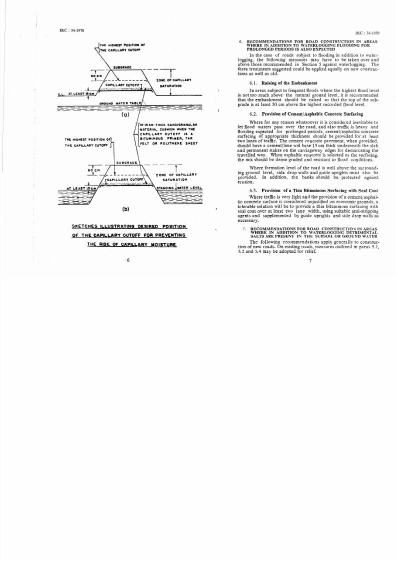
5.3. · Capillary Cutoff
. As an alternative to the recommendations contained in paras5.1 and 5.2, a capillary cutoff could be provided to arrest the capillary rise of water. Provision of capil lary cutoffs could, however,prove to be expensive; and maybe justified only in special circumstances.
The cutoff should be placed at least 15 em above the groundlevel or the standing water level, whichever be higher, as illustratedin figure on page 6. · But in no case should it be pJsiti,:meJ higherthan 60 em below the top of the s u b g r a d e ~ When provided, thecutoff medium should extend under the berms as well.
Suitable types of capillary cutoffs are listed under Section 8.When·t he cutoff medium selected is of the type bituminous primer,ta r felt or polythene envelope, it will be advisable t::> c;:,ver it with a10 to 15 em thick layer of granular material like s'lnd for the dualpurpose of acting as a drainage course for water infiltrating from thetop and of protecting the envelope during c::>nstruction against rupture by sharp particles in the fill material.
5.4. Providing Sufficient Thickness of the Pavement to beAdequate for Saturated Subgrade Conditions
In- case neither drains nor sufficiently high emb::tnkment norcapillary cutoff can be provided on an existing road, the thickness ofthe pavement should be determi ned on the basis of strength of the.
subgrade soil at saturation and strengthening carried out accordingly.
. This measure can be·· adopted in the case of new constructionsas well. In that event, at least 10·em thickness of sub-base. shouldbe made up .of such materi al as stabil ised soil, which will be stablewhen wet, so that it is not possible for the soft subgrade soil in saturated condition to work up into the voids.
5
7/27/2019 IRC 34-1970 Road in Waterlogged Areas
http://slidepdf.com/reader/full/irc-34-1970-road-in-waterlogged-areas 6/8
IRC: 34-1970
· G.L.
THE tUGHEST POSITION Of
THE CAPILLARY CUTOFF
THE. HIGHEST PO S!TION OF
THE CAPILLARY CUTOFF
(a )
(b)
. ZONE OF CAPILLARY
I0-15 em ni tCK SAND/GRANULAR
MATERIAL CUSHION WHEN THE
C A PIL LA R Y CUT 0 F F l S . A
.BITUMINOUS . PRIMER, TAR
FELT OR POLYTHENE SHEET
SK·ETCHES. lLl .USTR·ATlNG DESIRED POSITI_ON
Of THE- CAPILLARY CUTOFF FQR PREVENTING·
THE RISE OF CAPILL.ARY MOISTURE
·6
IRC: 34-1970
6. RECOMMENDATIONS FOR ROAD CONSTRUCTION IN AREASWHERE IN ADDITION TO WATERLOGGING FLOODING FORPROLONGED PERIODS IS ALSO EXPECTED
In the case of roads subject to flooding in addition to waterlogging, the following measures may have _to be taken over andabove those recommend ed in Section 5 against waterlogging._ Thethree treatments suggested could be applied equally on new constructions as well as old.
6.1. Raising of the Embankment
In areas subject to frequent floods where the highest flood levelis not too much above the natur al ground level, it is recommendedthat the embankment should be raised so that the top of the subgrade is at least 30 em above the highest recorded flood level.
6.2. Provision of Cement/ Asphaltic Concrete Surfacing
Where for any reason whatsoever it is considered inevitable tolet flood waters pass over the road, and also traffic is heavy andflooding expected for prolonged periods, cementjasphaltic concretesurfacing of appropriate thickness should be provided for at leasttwo lanes of traffic. The cement concrete pavement, when provided,should have a cement/lime soil base 15 em thick underneath the slaband permanent stakes on the carriageway edges for demarcating thetravelled way. When asphaltic concrete is selected as the surfacing,the mix should be dense graded and resistant to flood condition s.
Where formation level of the road is well above the surrounding ground level, side drop walls and guide uprights must also beprovided. In addition, the banks should be protected againsterosion.
6.3. Provision of a Thin Bituminous Surfacing with Seal Coat
Where traffic is very light and the provision of a cementfasphaltic concrete surface is considered unjustified on economic gr,aunds, atolerable solution will be to provide a thin bituminous surfacing withseal coat over at least two lane width, using suitable anti-strippingagents and supplem ented by guide uprights and side drop walls asnecessary.
7. RECOMMENDATIONS FOR ROAD C O N S T R U C T I O ~ IN AREASWHERE IN ADDITION TO WATERLOGGING DETRIMENTALSALTS ARE PRESENT IN T HE S UBSOIL OR GROUND WATER
The following recommendations apply generally to construction of new roads. On existing roads, measures outlined in paras 5, 1,5.2 and 5.4 may be adopted for relief.
7
7/27/2019 IRC 34-1970 Road in Waterlogged Areas
http://slidepdf.com/reader/full/irc-34-1970-road-in-waterlogged-areas 7/8
IRC : 34-1970
7.1. No special measures are considered necessary from thestandpoint of physicaljchemical action of injurious salts except thosestated in Sections 5 and 6 if the concentration of sulphates in the
subgrade soil is below 0.2 pe r cent (as sulphur trioxide) while alsobelow 0.03 per cent (as sulphu r trioxide) in ground water. Similarly,sodium carbonate concentrations of upto 0.2 per cent in subgradesoil and 0.02 per cent in the ground water are considered unharmful.Salt concentrations may be determined in accordance with the procedure laid down in relevant I.S.I. Standards-IS : 2720, part XXIII-1966 "Methods of Test for Soils : Determination of CalciumCarbonate", and IS : 2720, part XXVII-"Methods of Test forSoils : Determination of Total Sulphate".
No damage is expected from dissolved carbon dioxide or bicar
bonate salt solutions (met with in certain marshy areas) providedthe pH value of the solutions is higher than 5.
Where the concentration of these salts is in excess ·of the safelimits specified above, special measures as indi cated beldw are
recommended as a guide for road construction. These measures arein addition to those recommended in Section 5.
7 2. Flexible Pavements
7.2. I. . Water-bound macadam roads with or without bituminoussurfacing: . Even if concentration of salts in the subgrade or ground
water is higher than the safe limits prescribed in para 7.1, no specialmeasures other than those set forth in Section 5 are considerednecessary for wat er-bound macadam roads with or without bituminoussurfacing except that the filler used in water-bound macadam andsoling should be inert and free from injurious salts.
7.2.2. Stabilised Soil Constructions:
(a) Mechanical stabilisation
(b) Cement and lime stabilisat ion
(c) Bituminous stabilisation
If the above constructions are contemplated in waterloggedareas infested with salts, the soil used for stabilisation should no tcontain more than 0.2 per cent of total soluble sulphates andcarbonates.
Besides this, to preve nt the injurious salts in the' subgrade orground water from cqming into contact with stabilised soil courses, asuitable capillary cutoff out of those described in Section 8 should beprovided underneath the pavement extending across the full width
of the roadway, treating it as an essential measure.
8
IRC: 34-1970
7.3. Rigid Pavements
When sulphates are in excess of the safe limits prescribed . inpara 7.1, the following additional measures are recommended durmgthe construction of cement concrete pavements over and above theprovisions of paras 5.1 and 5.2.
7.3.1. Since all types of concrete, irrespective t y p ~ ?fcement used are more vulnerable to salt attack dunng tl1e Initialperiod of ha;dening than when fully set, it is of importa?ce to prevent contact between the ground water and concrete m the early
stages. Fo r this purpose, a p p l y i ~ g a l i g ~ t c?at of bitumen to t l ~ eunderside· of precast units, protectmg cast-m-sttu concrete thm
bituminised coating on the base just below the slab, or provisiOn of
one of the capillary cutoffs mentioned in Section 8,. are so!lle ofmeasures recommended for adoption under relatively mild condttions of exposures to sulphate attack, viz., when sulphate concentration in soil is upto about 0.5 per cent.
Under more severe conditions, i.e. when sulphates are. in ex*cessof 0.5 per cent, the bituminous coatings.l:lsed should be thicker asthey are known to possess higher durab1hty.
7.3.2. Furthermore, the following measures are suggested as
suitable for minimising adve rse chemical effect of the sulphates onconcrete:
(i) Designing a dense, w e l l - c o m p a c t ~ ~ ' high . q u a l i t ~ concretewhich will have low permeab1hty agmst mgress ofsulphat e solution. (This is recommended even when SOain water is above 0.02 per cent).
(ii) Use of special sulphate resistant cement, puzzolaniccement or super-sulphated blast furnace slag cement,depending on availability and e c o ~ 1 0 m ~ (when sulphatecontent is more than 0.3 per cent m soil and more than
0.03 per cent in ground water).
7.3.3. In areas where there is danger of damage from dissolvedcarbo n . dioxide or bicarbonate salts as evidenced by pH values ofbelow 5 the provision of a waterproof layer below the concretep a v e m e ~ t such as heavy duty bituminised paper or polythene sheet,and use ·a dense, well-compacted, high quality concrete are themeasures recommended for adoption.
*For the purposes of this specification,. thin coats.are c o n ~ i d e r e d to.be thos;in which the rate of application of straight-run. i t ! I m ~ n IS 12 kg per mand thick coats are those in which the rate of apphcat10n IS 20 kg per 10 m .
9

7/27/2019 IRC 34-1970 Road in Waterlogged Areas
http://slidepdf.com/reader/full/irc-34-1970-road-in-waterlogged-areas 8/8
IRC: 34-1970
8. SUITABLE CAPILLARY CUTOFFS
8. 1 Provision of Sand BlanketSand blanket of adequate thickness over the full width of
embankment is recommended as an effective capillary cutoff. The
thickness of the sand blanket needed to intercept capillarity dependson the particle size of the sand and may be determined from thefollowing formula*:
where
t
d
(8)0·92
-,r
thickness of sand layer in em2dt X d2
d1 + dz
mean particle diameter in mm
d1 aperture size of sieve (mm) through whichthe fraction passes
d2 aperture size of sieve (mm) on which thefraction is retained.
The sand shall be compacted after adding sufficiep.t moisture to
permit easy rolling. Alternatively, it might be compacted dry ifthe facility of vibratory roller was available.
8.2. Some of the Other Capillary Cutoffs**
8.2. I. Bituminous impregnation using primer treatment: 50 percent straight-run bitumen (80-100) with 50 per cent high speed
diesel oil or its equivalent in two applications of 10 kg per 10 mzeach, allowing the first application to penetrate before applying the
second one.
8.2.2. Heavy duty tar felt: Providing an envelope with heavyduty tar felt.
8.2.3. Polytbene envelope: Providing an envelope withpolythene sheets of at least 400 gauge.
8.2.4. Bituminous stabilised soil: Providing bituminousstabilised soil in a thickness of at least 4 em.
*This formula was proposed initially by the Public Roads Administrationand is published in Highway Research Board Proceedings, Vol. 21, 1941, page452. .
**Experience on· the successful performance· of capillary cutoffs suggestedin para 8.2 is, however, limited.
10