Embed Size (px)
Citation preview
Contract NGNDD01: Engagement of Detailed Design Consultant (DDC) for Civil, Architectural and E & M Works of
Noida-Greater Noida Metro Corridor from Sector – 51 Noida to Greater Noida Sector – 2, Consisting of 9.605 Km
Viaduct including 5 Elevated Stations
Part-I
OUTLINE DESIGN CRITERIA - RAILWAY GEOMETRY,
BRIDGES AND VIADUCTS
Contract NGNDD01: Engagement of Detailed Design Consultant (DDC) for Civil, Architectural and E & M Works of
Noida-Greater Noida Metro Corridor from Sector – 51 Noida to Greater Noida Sector – 2, Consisting of 9.605 Km
Viaduct including 5 Elevated Stations
Contract NGNDD01/Vol-4/Reference Documents/Part-I
1
CONTRACT NO: NGNDD01
INDEX
Section Title Page
D1 General Codes and Standards 2
D2 Geometric Design Criteria for Railway Alignment 13
D3 Railway Design Requirements 18
D4 Design Life and Service Ability 20
D5 Loads and Requirements 21
D6 Live Loads in Stations 25
D7 Elevated Structures 26
Contract NGNDD01: Engagement of Detailed Design Consultant (DDC) for Civil, Architectural and E & M Works of
Noida-Greater Noida Metro Corridor from Sector – 51 Noida to Greater Noida Sector – 2, Consisting of 9.605 Km
Viaduct including 5 Elevated Stations
Contract NGNDD01/Vol-4/Reference Documents/Part-I
2
OUTLINE DESIGN CRITERIA
RAILWAY GEOMETRY, BRIDGES AND VIADUCTS
Section D1 - GENERAL, CODES AND STANDARDS
D1.1 Purpose and Scope
D1.1.1 The Outline Design Specifications hereto provide minimum standards that are to
govern the Design of the Permanent Works.
D1.1.2 The Outline Design Specifications shall be read in conjunction with the Outline
Construction Specifications where ever appropriate.
D1.1.3 The design and construction of the Permanent Works shall comply with codes of
practice and standards current at the time of submission of Tender Documents.
Regulations made and requirements issued by the Government of India and by
relevant utility authorities shall be followed and specified.
D1.1.4 Alternative or additional codes, standards and specifications proposed by the DDC
shall be internationally recognised codes and shall be equivalent to or better than,
Indian Standards issued by the Bureau of Indian Standards or any other Indian
professional body or organisation, subject to being, in the opinion of the Engineer,
suitable for incorporation or reference into the Specifications.
D1.2 Codes and Standards
Design and loading requirements for the structures shall be not less than the following
Indian Standards and Codes of Practice, together with all applicable amendments.
Where other standards and codes of practice are referred to in the text of other
Appendices then the designer is expected to apply those Standards and Codes of
Practice unless the designer can show that an economic case exists for use of an
Indian Standard. However preferences of codes will be as follows :–
(1) IRS - Where any structures supporting railway tracks.
(2) IRC
(3) IS
(4) BS
(5) AASTO
Indian Railway Standards (IRS)
IRS - Bridge Rules for loading (Ministry of Railways)
IRS - Code of practice for steel bridges.
IRS- Code of practice for plain, reinforced and pre-stressed concrete for
general Bridge construction. Second Revision – 1997.
IRS- Code of practice for the design of substructures and foundation of
bridges
Contract NGNDD01: Engagement of Detailed Design Consultant (DDC) for Civil, Architectural and E & M Works of
Noida-Greater Noida Metro Corridor from Sector – 51 Noida to Greater Noida Sector – 2, Consisting of 9.605 Km
Viaduct including 5 Elevated Stations
Contract NGNDD01/Vol-4/Reference Documents/Part-I
3
.
Indian Roads Congress Standards (IRC)
IRC 5: 1985 Standard Specifications and Code of Practice for
Road Bridges, Section I - General Features of
Design
IRC 6: 2000 Standard Specifications and Code of Practice for
Road Bridges, Section II – Loads and Stresses
IRC 10: 1961 Recommended Practice for Borrowpits for Road
Embankments Constructed by Manual Operation
IRC 11: 1962 Recommended practice for the design of layout of
cycle tracks
IRC 18: 1985 Design Criteria for Prestressed Concrete Road
Bridges (Post-Tensioned Concrete)
IRC 19: 1977 Standard Specifications and code of Practice for
Water Bound Macadam
IRC 21: 1987 Standard Specifications and Code of Practice
for Road Bridges Section III–Cement Concrete
(Plain and Reinforced)
IRC 22: 1986 Standard Specifications and Code of Practice for
Road Bridges, Section VI – Composite
Construction
IRC 24: 1967 Standard Specifications and Code of practice for
Road Bridges, Section V – Steel Road Bridges
IRC 36: 1970 Recommended Practice for the Construction of
Earth Embankments for Road Works
IRC 37: 1984 Guidelines for the Design of Flexible Pavement
IRC 45: 1972 Recommendations for Estimating the Resistance
of Soil below the maximum Scour Level in the
Design of Well Foundations of Bridges
IRC 48: 1972 Tentative Specifications for Bituminous Surface
Dressing Using Pre-coated Aggregates
IRC 75: 1979 Guidelines for the Design of High Embankments
IRC 78: 2000 Standard Specifications and Code of Practice for
Road Bridges, Section VII (Parts 1 and 2),
Foundations and Substructure
IRC 83: 1987 Standard Specifications and code of practice for
Road Bridges, Section IX - Bearings Part I & II:
Bearings (Metallic and Elastomeric)
IRC 87: 1984 Guidelines for the Design and Erection of False
Work for Road Bridges
Contract NGNDD01: Engagement of Detailed Design Consultant (DDC) for Civil, Architectural and E & M Works of
Noida-Greater Noida Metro Corridor from Sector – 51 Noida to Greater Noida Sector – 2, Consisting of 9.605 Km
Viaduct including 5 Elevated Stations
Contract NGNDD01/Vol-4/Reference Documents/Part-I
4
IRC 89: 1997 Guidelines for Design and Construction of River
Training and Control Works for Road Bridges
IRC: SP 11 1988 Handbook of Quality Control for Construction of
Roads and Runaways
D1.5 IS: Codes
National Building Code
SP 7: 1983 Bureau of Indian Standards.
IS 73: 1992 Paving Bitumen
IS 150: 1950 Ready mixed paint brushing, finishing stoving for
enamel colour as required
IS 205: 1992 Non-ferrous metal Butt Hinges
IS 206: 1992 Tee and strap hinges
IS 207: 1964 Gate and shutter hooks and eyes
IS 208: 1987 Door handles
IS 210: 1993 Grey iron castings
IS 215: 1995 Road tar
IS 217: 1988 Cutback Bitumen
IS 269: 1989 33 grade Ordinary Portland Cement.
IS 278: 1978 Galvanised steel barbed wire for fencing
IS 280: 1978 Mild Steel wire for general engineering Purposes
IS 281: 1991 Mild Steel sliding door bolts for use with Padlocks
IS 362: 1991 Parliament hinges
IS 363: 1993 Hasps and staples
IS 383: 1970 Coarse and fine aggregates from natural Sources
for concrete
IS 432: 1982 Mild steel and medium tensile steel bars and hard-
drawn steel wire for concrete reinforcement
(Part 1) Mild steel and medium tensile steel bars
(Part 2) Hard-drawn steel wire
IS 453: 1993 Double-acting spring hinges
IS 455: 1989 Portland slag cement
IS 456: 2000 Code of practice for plain and reinforced concrete
IS 457: 1957 Code of practice for general construction of plain
and reinforced concrete for dams and other
massive structures
IS 458: 1988 Precast concrete pipes (with and without
reinforcement)
Contract NGNDD01: Engagement of Detailed Design Consultant (DDC) for Civil, Architectural and E & M Works of
Noida-Greater Noida Metro Corridor from Sector – 51 Noida to Greater Noida Sector – 2, Consisting of 9.605 Km
Viaduct including 5 Elevated Stations
Contract NGNDD01/Vol-4/Reference Documents/Part-I
5
IS 459: 1992 Corrugated and semi-corrugated asbestos cement
sheets
IS 460: 1985 Test sieves
IS 516: 1959 Method of test for strength of concrete
IS 650: 1991 Standard sand for testing cement
IS 733: 1983 Wrought aluminium and aluminium alloy bars,
rods and sections for general engineering
purposes
IS 737 1986 Wrought aluminium and aluminium alloy sheet
and strip for general engineering purposes
IS 771 1979 Glazed fire-clay sanitary appliances
(Part 1) General requirements
(Part 2) Specific requirements of Kitchen and laboratory
sinks
(Part 3/Sec. 1) Specific requirements of Urinals - Slab
Urinals
(Part 3/Sec. 2) Specific requirements of Urinals - Stall
Urinals
IS 774: 1984 Flushing cistern for water closets and urinals
IS 775: 1970 Cast iron brackets and supports for wash basins
and sinks
IS 777: 1988 Glazed earthenware wall tiles
IS 778: 1984 Copper Alloy gate, globe and check valves for
water works purposes
IS 779: 1994 Water meters
IS 780: 1984 Sluice valves for water works purposes (50 to 300
mm size)
IS 781: 1984 Cast copper alloy screw down bib taps and stop
valves for water services
IS 783: 1985 Code of practice for laying of concrete pipes
IS 800: 1984 Code of practice for general construction in steel
IS 814: 1991 Covered electrodes for manual metal arc welding
of carbon and carbon manganese steel
IS 875: 1987 Code of practice for design loads (other than
earthquake) for buildings and structures
IS 883: 1994 Code of practice for design of structural timber in
building
IS 909: 1992 Under-ground fire hydrant, sluice valve type
IS 1003: Timber panelled and glazed shutters
Contract NGNDD01: Engagement of Detailed Design Consultant (DDC) for Civil, Architectural and E & M Works of
Noida-Greater Noida Metro Corridor from Sector – 51 Noida to Greater Noida Sector – 2, Consisting of 9.605 Km
Viaduct including 5 Elevated Stations
Contract NGNDD01/Vol-4/Reference Documents/Part-I
6
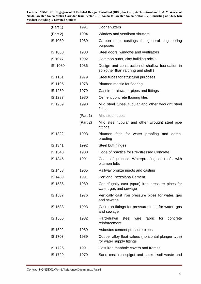
(Part 1) 1991 Door shutters
(Part 2) 1994 Window and ventilator shutters
IS 1030: 1989 Carbon steel castings for general engineering
purposes
IS 1038: 1983 Steel doors, windows and ventilators
IS 1077: 1992 Common burnt, clay building bricks
IS 1080: 1986 Design and construction of shallow foundation in
soil(other than raft ring and shell )
IS 1161: 1979 Steel tubes for structural purposes
IS 1195: 1978 Bitumen mastic for flooring
IS 1230: 1979 Cast iron rainwater pipes and fittings
IS 1237: 1980 Cement concrete flooring tiles
IS 1239: 1990 Mild steel tubes, tubular and other wrought steel
fittings
(Part 1) Mild steel tubes
(Part 2) Mild steel tubular and other wrought steel pipe
fittings
IS 1322: 1993 Bitumen felts for water proofing and damp-
proofing
IS 1341: 1992 Steel butt hinges
IS 1343: 1980 Code of practice for Pre-stressed Concrete
IS 1346: 1991 Code of practice Waterproofing of roofs with
bitumen felts
IS 1458: 1965 Railway bronze ingots and casting
IS 1489: 1991 Portland Pozzolana Cement.
IS 1536: 1989 Centrifugally cast (spun) iron pressure pipes for
water, gas and sewage
IS 1537: 1976 Vertically cast iron pressure pipes for water, gas
and sewage
IS 1538: 1993 Cast iron fittings for pressure pipes for water, gas
and sewage
IS 1566: 1982 Hard-drawn steel wire fabric for concrete
reinforcement
IS 1592: 1989 Asbestos cement pressure pipes
IS 1703: 1989 Copper alloy float values (horizontal plunger type)
for water supply fittings
IS 1726: 1991 Cast iron manhole covers and frames
IS 1729: 1979 Sand cast iron spigot and socket soil waste and
Contract NGNDD01: Engagement of Detailed Design Consultant (DDC) for Civil, Architectural and E & M Works of
Noida-Greater Noida Metro Corridor from Sector – 51 Noida to Greater Noida Sector – 2, Consisting of 9.605 Km
Viaduct including 5 Elevated Stations
Contract NGNDD01/Vol-4/Reference Documents/Part-I
7
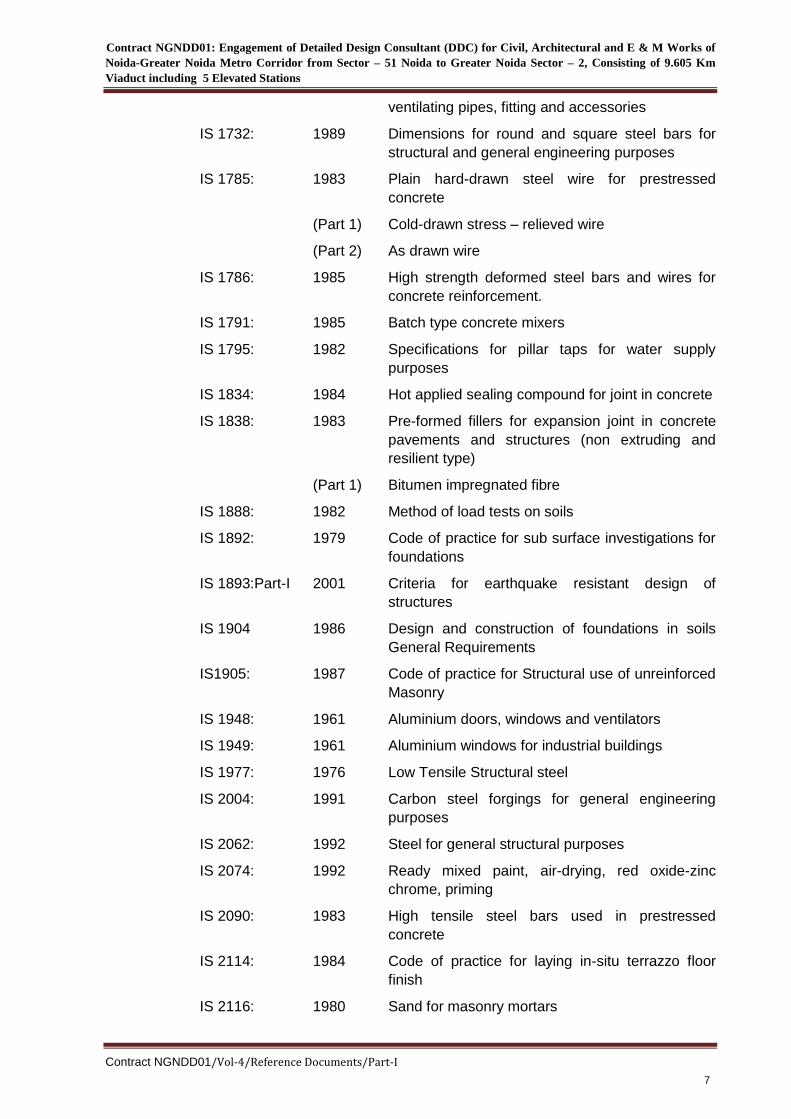
ventilating pipes, fitting and accessories
IS 1732: 1989 Dimensions for round and square steel bars for
structural and general engineering purposes
IS 1785: 1983 Plain hard-drawn steel wire for prestressed
concrete
(Part 1) Cold-drawn stress – relieved wire
(Part 2) As drawn wire
IS 1786: 1985 High strength deformed steel bars and wires for
concrete reinforcement.
IS 1791: 1985 Batch type concrete mixers
IS 1795: 1982 Specifications for pillar taps for water supply
purposes
IS 1834: 1984 Hot applied sealing compound for joint in concrete
IS 1838: 1983 Pre-formed fillers for expansion joint in concrete
pavements and structures (non extruding and
resilient type)
(Part 1) Bitumen impregnated fibre
IS 1888: 1982 Method of load tests on soils
IS 1892: 1979 Code of practice for sub surface investigations for
foundations
IS 1893:Part-I 2001 Criteria for earthquake resistant design of
structures
IS 1904 1986 Design and construction of foundations in soils
General Requirements
IS1905: 1987 Code of practice for Structural use of unreinforced
Masonry
IS 1948: 1961 Aluminium doors, windows and ventilators
IS 1949: 1961 Aluminium windows for industrial buildings
IS 1977: 1976 Low Tensile Structural steel
IS 2004: 1991 Carbon steel forgings for general engineering
purposes
IS 2062: 1992 Steel for general structural purposes
IS 2074: 1992 Ready mixed paint, air-drying, red oxide-zinc
chrome, priming
IS 2090: 1983 High tensile steel bars used in prestressed
concrete
IS 2114: 1984 Code of practice for laying in-situ terrazzo floor
finish
IS 2116: 1980 Sand for masonry mortars
Contract NGNDD01: Engagement of Detailed Design Consultant (DDC) for Civil, Architectural and E & M Works of
Noida-Greater Noida Metro Corridor from Sector – 51 Noida to Greater Noida Sector – 2, Consisting of 9.605 Km
Viaduct including 5 Elevated Stations
Contract NGNDD01/Vol-4/Reference Documents/Part-I
8
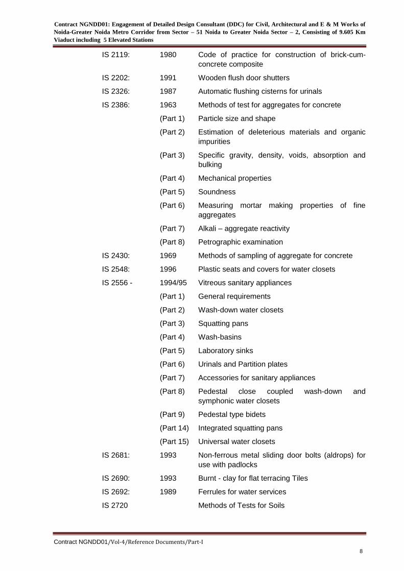
IS 2119: 1980 Code of practice for construction of brick-cum-
concrete composite
IS 2202: 1991 Wooden flush door shutters
IS 2326: 1987 Automatic flushing cisterns for urinals
IS 2386: 1963 Methods of test for aggregates for concrete
(Part 1) Particle size and shape
(Part 2) Estimation of deleterious materials and organic
impurities
(Part 3) Specific gravity, density, voids, absorption and
bulking
(Part 4) Mechanical properties
(Part 5) Soundness
(Part 6) Measuring mortar making properties of fine
aggregates
(Part 7) Alkali – aggregate reactivity
(Part 8) Petrographic examination
IS 2430: 1969 Methods of sampling of aggregate for concrete
IS 2548: 1996 Plastic seats and covers for water closets
IS 2556 - 1994/95 Vitreous sanitary appliances
(Part 1) General requirements
(Part 2) Wash-down water closets
(Part 3) Squatting pans
(Part 4) Wash-basins
(Part 5) Laboratory sinks
(Part 6) Urinals and Partition plates
(Part 7) Accessories for sanitary appliances
(Part 8) Pedestal close coupled wash-down and
symphonic water closets
(Part 9) Pedestal type bidets
(Part 14) Integrated squatting pans
(Part 15) Universal water closets
IS 2681: 1993 Non-ferrous metal sliding door bolts (aldrops) for
use with padlocks
IS 2690: 1993 Burnt - clay for flat terracing Tiles
IS 2692: 1989 Ferrules for water services
IS 2720 Methods of Tests for Soils
Contract NGNDD01: Engagement of Detailed Design Consultant (DDC) for Civil, Architectural and E & M Works of
Noida-Greater Noida Metro Corridor from Sector – 51 Noida to Greater Noida Sector – 2, Consisting of 9.605 Km
Viaduct including 5 Elevated Stations
Contract NGNDD01/Vol-4/Reference Documents/Part-I
9
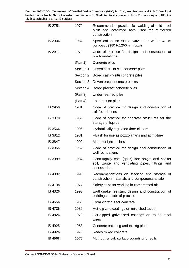
IS 2751: 1979 Recommended practice for welding of mild steel
plain and deformed bars used for reinforced
construction
IS 2906: 1984 Specification for sluice valves for water works
purposes (350 to1200 mm size)
IS 2911: 1979 Code of practice for design and construction of
pile foundations
(Part 1) Concrete piles
Section 1 Driven cast –in-situ concrete piles
Section 2 Bored cast-in-situ concrete piles
Section 3 Driven precast concrete piles
Section 4 Bored precast concrete piles
(Part 3) Under-reamed piles
(Part 4) Load test on piles
IS 2950: 1981 Code of practice for design and construction of
raft foundations
IS 3370: 1965 Code of practice for concrete structures for the
storage of liquids
IS 3564: 1995 Hydraulically regulated door closers
IS 3812: 1981 Flyash for use as pozzolanans and admixture
IS 3847: 1992 Mortice night latches
IS 3955: 1967 Code of practice for design and construction of
well foundations
IS 3989: 1984 Centrifugally cast (spun) iron spigot and socket
soil, waste and ventilating pipes, fittings and
accessories
IS 4082: 1996 Recommendations on stacking and storage of
construction materials and components at site
IS 4138: 1977 Safety code for working in compressed air
IS 4326: 1993 Earthquake resistant design and construction of
buildings – code of practice
IS 4656: 1968 Form vibrators for concrete
IS 4736: 1986 Hot-dip zinc coatings on mild steel tubes
IS 4826: 1979 Hot-dipped galvanised coatings on round steel
wires
IS 4925: 1968 Concrete batching and mixing plant
IS 4926: 1976 Ready mixed concrete
IS 4968: 1976 Method for sub surface sounding for soils
Contract NGNDD01: Engagement of Detailed Design Consultant (DDC) for Civil, Architectural and E & M Works of
Noida-Greater Noida Metro Corridor from Sector – 51 Noida to Greater Noida Sector – 2, Consisting of 9.605 Km
Viaduct including 5 Elevated Stations
Contract NGNDD01/Vol-4/Reference Documents/Part-I
10
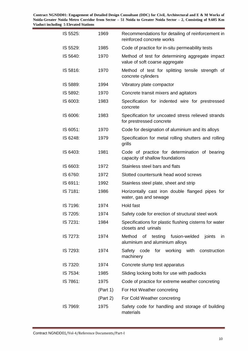
IS 5525: 1969 Recommendations for detailing of reinforcement in
reinforced concrete works
IS 5529: 1985 Code of practice for in-situ permeability tests
IS 5640: 1970 Method of test for determining aggregate impact
value of soft coarse aggregate
IS 5816: 1970 Method of test for splitting tensile strength of
concrete cylinders
IS 5889: 1994 Vibratory plate compactor
IS 5892: 1970 Concrete transit mixers and agitators
IS 6003: 1983 Specification for indented wire for prestressed
concrete
IS 6006: 1983 Specification for uncoated stress relieved strands
for prestressed concrete
IS 6051: 1970 Code for designation of aluminium and its alloys
IS 6248: 1979 Specification for metal rolling shutters and rolling
grills
IS 6403: 1981 Code of practice for determination of bearing
capacity of shallow foundations
IS 6603: 1972 Stainless steel bars and flats
IS 6760: 1972 Slotted countersunk head wood screws
IS 6911: 1992 Stainless steel plate, sheet and strip
IS 7181: 1986 Horizontally cast iron double flanged pipes for
water, gas and sewage
IS 7196: 1974 Hold fast
IS 7205: 1974 Safety code for erection of structural steel work
IS 7231: 1984 Specifications for plastic flushing cisterns for water
closets and urinals
IS 7273: 1974 Method of testing fusion-welded joints in
aluminium and aluminium alloys
IS 7293: 1974 Safety code for working with construction
machinery
IS 7320: 1974 Concrete slump test apparatus
IS 7534: 1985 Sliding locking bolts for use with padlocks
IS 7861: 1975 Code of practice for extreme weather concreting
(Part 1) For Hot Weather concreting
(Part 2) For Cold Weather concreting
IS 7969: 1975 Safety code for handling and storage of building
materials
Contract NGNDD01: Engagement of Detailed Design Consultant (DDC) for Civil, Architectural and E & M Works of
Noida-Greater Noida Metro Corridor from Sector – 51 Noida to Greater Noida Sector – 2, Consisting of 9.605 Km
Viaduct including 5 Elevated Stations
Contract NGNDD01/Vol-4/Reference Documents/Part-I
11
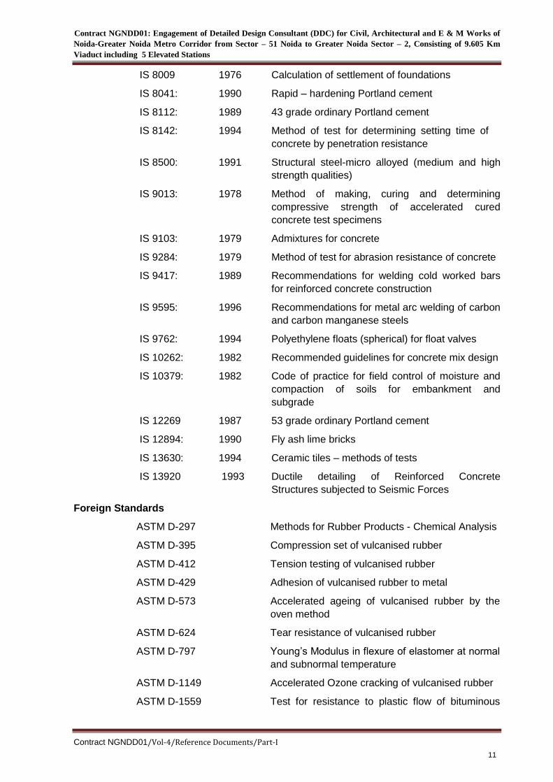
IS 8009 1976 Calculation of settlement of foundations
IS 8041: 1990 Rapid – hardening Portland cement
IS 8112: 1989 43 grade ordinary Portland cement
IS 8142: 1994 Method of test for determining setting time of
concrete by penetration resistance
IS 8500: 1991 Structural steel-micro alloyed (medium and high
strength qualities)
IS 9013: 1978 Method of making, curing and determining
compressive strength of accelerated cured
concrete test specimens
IS 9103: 1979 Admixtures for concrete
IS 9284: 1979 Method of test for abrasion resistance of concrete
IS 9417: 1989 Recommendations for welding cold worked bars
for reinforced concrete construction
IS 9595: 1996 Recommendations for metal arc welding of carbon
and carbon manganese steels
IS 9762: 1994 Polyethylene floats (spherical) for float valves
IS 10262: 1982 Recommended guidelines for concrete mix design
IS 10379: 1982 Code of practice for field control of moisture and
compaction of soils for embankment and
subgrade
IS 12269 1987 53 grade ordinary Portland cement
IS 12894: 1990 Fly ash lime bricks
IS 13630: 1994 Ceramic tiles – methods of tests
IS 13920 1993 Ductile detailing of Reinforced Concrete
Structures subjected to Seismic Forces
Foreign Standards
ASTM D-297 Methods for Rubber Products - Chemical Analysis
ASTM D-395 Compression set of vulcanised rubber
ASTM D-412 Tension testing of vulcanised rubber
ASTM D-429 Adhesion of vulcanised rubber to metal
ASTM D-573 Accelerated ageing of vulcanised rubber by the
oven method
ASTM D-624 Tear resistance of vulcanised rubber
ASTM D-797 Young’s Modulus in flexure of elastomer at normal
and subnormal temperature
ASTM D-1149 Accelerated Ozone cracking of vulcanised rubber
ASTM D-1559 Test for resistance to plastic flow of bituminous
Contract NGNDD01: Engagement of Detailed Design Consultant (DDC) for Civil, Architectural and E & M Works of
Noida-Greater Noida Metro Corridor from Sector – 51 Noida to Greater Noida Sector – 2, Consisting of 9.605 Km
Viaduct including 5 Elevated Stations
Contract NGNDD01/Vol-4/Reference Documents/Part-I
12
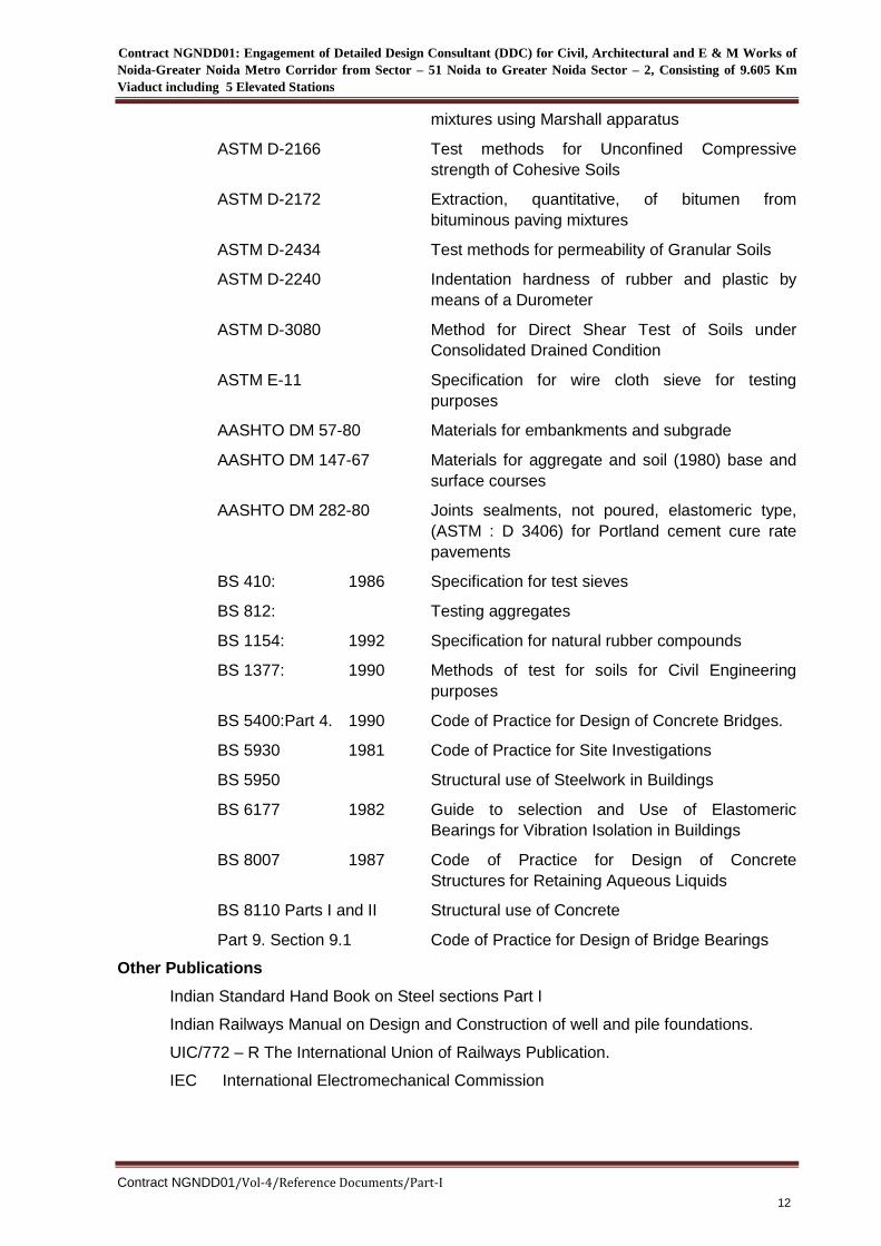
mixtures using Marshall apparatus
ASTM D-2166 Test methods for Unconfined Compressive
strength of Cohesive Soils
ASTM D-2172 Extraction, quantitative, of bitumen from
bituminous paving mixtures
ASTM D-2434 Test methods for permeability of Granular Soils
ASTM D-2240 Indentation hardness of rubber and plastic by
means of a Durometer
ASTM D-3080 Method for Direct Shear Test of Soils under
Consolidated Drained Condition
ASTM E-11 Specification for wire cloth sieve for testing
purposes
AASHTO DM 57-80 Materials for embankments and subgrade
AASHTO DM 147-67 Materials for aggregate and soil (1980) base and
surface courses
AASHTO DM 282-80 Joints sealments, not poured, elastomeric type,
(ASTM : D 3406) for Portland cement cure rate
pavements
BS 410: 1986 Specification for test sieves
BS 812: Testing aggregates
BS 1154: 1992 Specification for natural rubber compounds
BS 1377: 1990 Methods of test for soils for Civil Engineering
purposes
BS 5400:Part 4. 1990 Code of Practice for Design of Concrete Bridges.
BS 5930 1981 Code of Practice for Site Investigations
BS 5950 Structural use of Steelwork in Buildings
BS 6177 1982 Guide to selection and Use of Elastomeric
Bearings for Vibration Isolation in Buildings
BS 8007 1987 Code of Practice for Design of Concrete
Structures for Retaining Aqueous Liquids
BS 8110 Parts I and II Structural use of Concrete
Part 9. Section 9.1 Code of Practice for Design of Bridge Bearings
Other Publications
Indian Standard Hand Book on Steel sections Part I
Indian Railways Manual on Design and Construction of well and pile foundations.
UIC/772 – R The International Union of Railways Publication.
IEC International Electromechanical Commission
Contract NGNDD01: Engagement of Detailed Design Consultant (DDC) for Civil, Architectural and E & M Works of
Noida-Greater Noida Metro Corridor from Sector – 51 Noida to Greater Noida Sector – 2, Consisting of 9.605 Km
Viaduct including 5 Elevated Stations
Contract NGNDD01/Vol-4/Reference Documents/Part-I
13
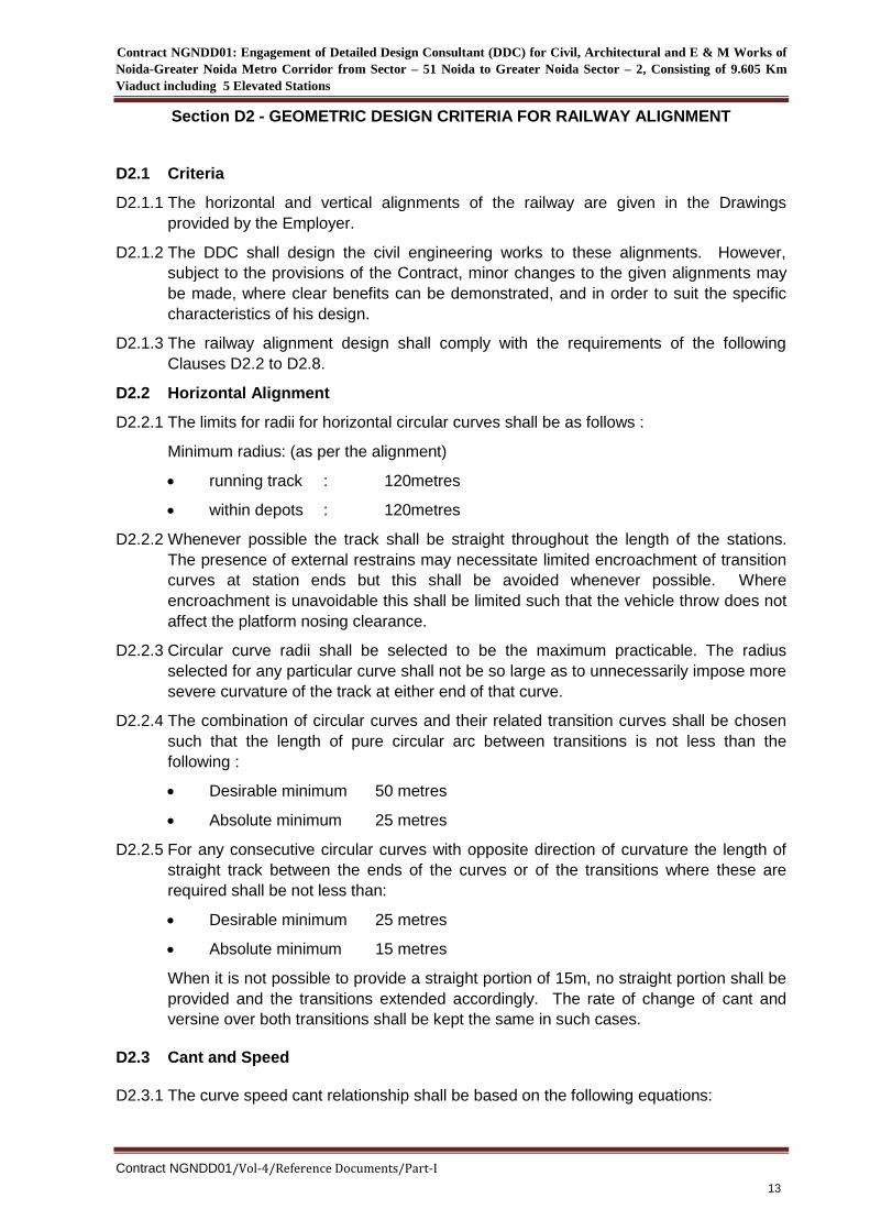
Section D2 - GEOMETRIC DESIGN CRITERIA FOR RAILWAY ALIGNMENT
D2.1 Criteria
D2.1.1 The horizontal and vertical alignments of the railway are given in the Drawings
provided by the Employer.
D2.1.2 The DDC shall design the civil engineering works to these alignments. However,
subject to the provisions of the Contract, minor changes to the given alignments may
be made, where clear benefits can be demonstrated, and in order to suit the specific
characteristics of his design.
D2.1.3 The railway alignment design shall comply with the requirements of the following
Clauses D2.2 to D2.8.
D2.2 Horizontal Alignment
D2.2.1 The limits for radii for horizontal circular curves shall be as follows :
Minimum radius: (as per the alignment)
running track : 120metres
within depots : 120metres
D2.2.2 Whenever possible the track shall be straight throughout the length of the stations.
The presence of external restrains may necessitate limited encroachment of transition
curves at station ends but this shall be avoided whenever possible. Where
encroachment is unavoidable this shall be limited such that the vehicle throw does not
affect the platform nosing clearance.
D2.2.3 Circular curve radii shall be selected to be the maximum practicable. The radius
selected for any particular curve shall not be so large as to unnecessarily impose more
severe curvature of the track at either end of that curve.
D2.2.4 The combination of circular curves and their related transition curves shall be chosen
such that the length of pure circular arc between transitions is not less than the
following :
Desirable minimum 50 metres
Absolute minimum 25 metres
D2.2.5 For any consecutive circular curves with opposite direction of curvature the length of
straight track between the ends of the curves or of the transitions where these are
required shall be not less than:
Desirable minimum 25 metres
Absolute minimum 15 metres
When it is not possible to provide a straight portion of 15m, no straight portion shall be
provided and the transitions extended accordingly. The rate of change of cant and
versine over both transitions shall be kept the same in such cases.
D2.3 Cant and Speed
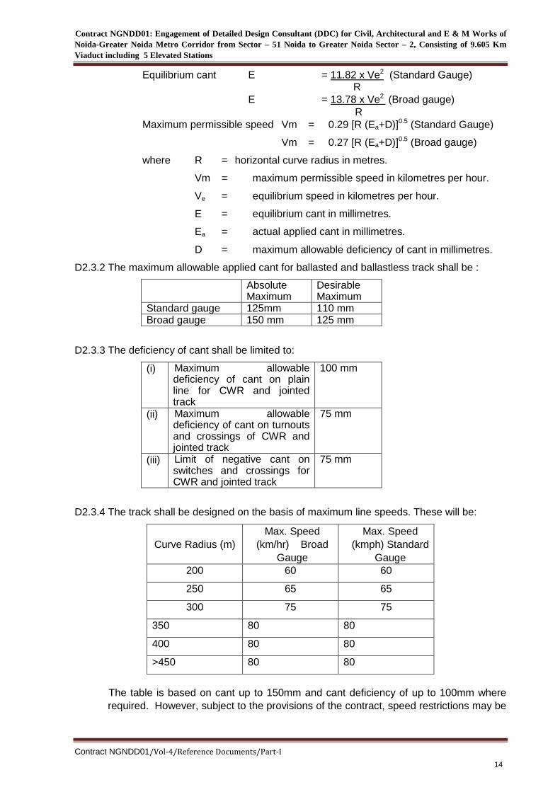
D2.3.1 The curve speed cant relationship shall be based on the following equations:
Contract NGNDD01: Engagement of Detailed Design Consultant (DDC) for Civil, Architectural and E & M Works of
Noida-Greater Noida Metro Corridor from Sector – 51 Noida to Greater Noida Sector – 2, Consisting of 9.605 Km
Viaduct including 5 Elevated Stations
Contract NGNDD01/Vol-4/Reference Documents/Part-I
14
Equilibrium cant E = 11.82 x Ve2 (Standard Gauge)
R
E = 13.78 x Ve2 (Broad gauge)
R
Maximum permissible speed Vm = 0.29 [R (Ea+D)]0.5 (Standard Gauge)
Vm = 0.27 [R (Ea+D)]0.5 (Broad gauge)
where R = horizontal curve radius in metres.
Vm = maximum permissible speed in kilometres per hour.
Ve = equilibrium speed in kilometres per hour.
E = equilibrium cant in millimetres.
Ea = actual applied cant in millimetres.
D = maximum allowable deficiency of cant in millimetres.
D2.3.2 The maximum allowable applied cant for ballasted and ballastless track shall be :
Absolute Maximum
Desirable Maximum
Standard gauge 125mm 110 mm Broad gauge 150 mm 125 mm
D2.3.3 The deficiency of cant shall be limited to:
(i) Maximum allowable deficiency of cant on plain line for CWR and jointed track
100 mm
(ii) Maximum allowable deficiency of cant on turnouts and crossings of CWR and jointed track
75 mm
(iii) Limit of negative cant on switches and crossings for CWR and jointed track
75 mm
D2.3.4 The track shall be designed on the basis of maximum line speeds. These will be:
Curve Radius (m)
Max. Speed
(km/hr) Broad
Gauge
Max. Speed
(kmph) Standard
Gauge
200 60 60
250 65 65
300 75 75
350 80 80
400 80 80
>450 80 80
The table is based on cant up to 150mm and cant deficiency of up to 100mm where
required. However, subject to the provisions of the contract, speed restrictions may be
Contract NGNDD01: Engagement of Detailed Design Consultant (DDC) for Civil, Architectural and E & M Works of
Noida-Greater Noida Metro Corridor from Sector – 51 Noida to Greater Noida Sector – 2, Consisting of 9.605 Km
Viaduct including 5 Elevated Stations
Contract NGNDD01/Vol-4/Reference Documents/Part-I
15
introduced where this is dictated by external constraints and operational requirements.
D2.3.5 Applied cant shall be specified to the nearest millimetre for concrete track and to the
nearest 5 mm for ballasted track.
D2.3.6 Track at terminus stations shall continue past the end of the platforms by 25 metres
where stabling or refuge tracks are not required.
D2.4 Transition Curves
D2.4.1 In general for all running and depot lines transition curves shall be provided wherever
possible between a circular curve and adjoining straight, between the different radii of
a compound curve and at the adjoining ends of circular curves forming reverse curves.
Transition curves are not required in sidings.
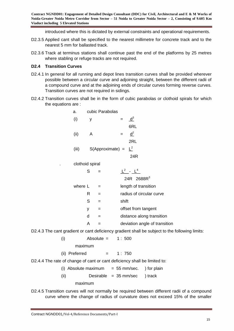
D2.4.2 Transition curves shall be in the form of cubic parabolas or clothoid spirals for which
the equations are :
a. cubic Parabolas
(i) y = d3
6RL
(ii) A = d2
2RL
(iii) S(Approximate) = L2
24R
. clothoid spiral
S = L2 - L4
24R 2688R3
where L = length of transition
R = radius of circular curve
S = shift
y = offset from tangent
d = distance along transition
A = deviation angle of transition
D2.4.3 The cant gradient or cant deficiency gradient shall be subject to the following limits:
(i) Absolute
maximum
= 1 : 500
(ii) Preferred = 1 : 750
D2.4.4 The rate of change of cant or cant deficiency shall be limited to:
(i) Absolute maximum
(ii) Desirable
maximum
= 55 mm/sec.
= 35 mm/sec
) for plain
) track
D2.4.5 Transition curves will not normally be required between different radii of a compound
curve where the change of radius of curvature does not exceed 15% of the smaller
Contract NGNDD01: Engagement of Detailed Design Consultant (DDC) for Civil, Architectural and E & M Works of
Noida-Greater Noida Metro Corridor from Sector – 51 Noida to Greater Noida Sector – 2, Consisting of 9.605 Km
Viaduct including 5 Elevated Stations
Contract NGNDD01/Vol-4/Reference Documents/Part-I
16
radius and provided that the cant deficiency and/or cant excess criteria are not
exceeded for either curve.
Where a compound curve is employed with a change of radius greater than 15% of the
smaller radius, or where the cant deficiency or cant excess criteria necessitates a
change in cant between the circular curves, a suitable transition curve shall be
interposed between the two parts of the curve. The length of such a transition shall be
equal to the difference between the required transition lengths at each end of the
curve.
When the actual shift of any calculated transition curve would be less than 10mm the
actual transition curve may be omitted. In this case, the required change of cant shall
take place over the calculated length of the transition, or 15 m which ever is the
greater, and in the same location as if the transition had been provided.
D2.5 Vertical Alignment
D2.5.1 Vertical curves shall wherever possible be positioned such that coincidence with
horizontal transitions is avoided. Where such coincidence is unavoidable the largest
practicable vertical curve radius shall be employed.
D2.5.2 Vertical curves shall, for each location, be selected on the basis of the largest
practicable vertical curve radius subject to the following limit :
Minimum desirable radius 2500 m
D2.5.3 The length of constant grade between consecutive vertical curves shall be as follows:
(i) Desirable minimum 50 m
(ii) Absolute minimum 25 m
D2.5.4 At point and crossing work vertical curves shall not coincide with any part of the overall
length of switches or of cast crossings. At other point and crossing work vertical
curves shall be avoided whenever possible. Where they cannot be avoided the
vertical curve radius shall be 3000 m or more
D2.5.5 At station ends the tangent point of the vertical curve shall be permitted to encroach
within the length of the platform to a limited extent. This length of encroachment shall
be such that the vertical offset of the curve from the station gradient at the platform
end shall not exceed 15mm.
D2.6 Gradients
D2.6.1 The limits for gradients shall be as follows :
For running lines the desirable maximum gradient shall be 3% and where
unavoidable shall be 4%. Where gradients of 1% or less are used they may be
unrestricted in length. Gradients above 3.0% shall be kept as short as possible.
At stations the track shall be level or of constant gradient not steeper than 0.2%
throughout the platform length except for the limited lengths of vertical curves as
specified in Clause D2.5.5 above.
A drainage gradient shall be provided for all viaducts, other than at stations, as
follows :
Desirable minimum 0.5%
Absolute minimum 0.25%
Contract NGNDD01: Engagement of Detailed Design Consultant (DDC) for Civil, Architectural and E & M Works of
Noida-Greater Noida Metro Corridor from Sector – 51 Noida to Greater Noida Sector – 2, Consisting of 9.605 Km
Viaduct including 5 Elevated Stations
Contract NGNDD01/Vol-4/Reference Documents/Part-I
17
Sidings shall be level or shall fall away from the main line switch at a gradient not
exceeding 0.25%. Train berths shall be level or shall fall towards the buffer stops at
a gradient not exceeding 0.25%.
D2.7 Levels
D2.7.1 All levels shall be quoted in metres correct to three decimal places and shall be above
mean sea level (MSL).
D2.7.2 Rail level on canted track will refer to the level of the running edge of the lower rail.
D2.8 Points and Crossing Work
D2.8.1 General
Whenever possible points and crossing work shall not coincide with vertically or
horizontally curved track.
Where it is not possible to avoid coincidence with vertical curves the switches and
stock rails shall not be laid on vertical curves.
Points and crossing work shall not coincide with horizontal transitions.
No part of the switches, switch operating gear or crossing nose shall be over a
structural movement joint.
D2.8.2 Scissors Crossovers
Scissors crossovers shall be based on a transitioned crossover with vertical rails.
The switch points and turnout radius shall be standard UIC or approved equivalent,
designed to accommodate a minimum operational speed of 40 km/hr.
D2.8.3 Turnouts
Turnouts shall be based on a transitioned turnout with vertical rails.
The speed through the turnout shall be 50 km/hr.
Operational speed in the Depot shall be 20 km/hr.
D2.8.4 Trackwork Requirement :
The Contractor shall design the viaduct structures in accordance with trackwork
requirements. All the structural elements of the viaducts including the locations of
expansion joints shall be designed so that they will not interfere with the operation of
the trackwork requirement and turnouts and crossovers.
Contract NGNDD01: Engagement of Detailed Design Consultant (DDC) for Civil, Architectural and E & M Works of
Noida-Greater Noida Metro Corridor from Sector – 51 Noida to Greater Noida Sector – 2, Consisting of 9.605 Km
Viaduct including 5 Elevated Stations
Contract NGNDD01/Vol-4/Reference Documents/Part-I
18
Section D3 - RAILWAY DESIGN REQUIREMENTS
D3.1 General
D3.1.1 The Railway Envelope is defined as the extent of works to be constructed to allow
installation and operation of the railway equipment.
D3.1.2 The DDC shall be responsible for the design, of a first stage primary concrete. Others
will undertake the design of the secondary concrete, trackslabs and trackwork under
contracts with the NMRC. A fundamental obligation of the DDC is to co-ordinate and
co-operate with the Trackwork DDC and Contractor so that the design of all
components of the railway are compatible.
D3.1.3 The design of all railway operating equipment, including signals and signalling cables,
the traction power electrification equipment, electrical cables, electrical and mechanical
equipment, telecommunication links, etc. that are required for the railway will be
undertaken by others under contracts with the Employer. Similar co-ordination and co-
operation obligations as expressed in Clause D3.1.2 above apply.
D3.1.4 The DDC shall include in the civil works blind holes, plinths, trenches etc. as required
by the Systemwide Contractors. The Systemwide Contractors will supply and fit
brackets, nuts and bolts and other fixings for the support of its equipment. The extent
and detail of such provisions are to be determined by the DDC making due enquiries,
through design co-ordination, from Contractors engaged to provide railway-operating
equipment and from the Trackwork DDC. Some details of the likely fixing to be
provided are given below but it is stressed that this information may not be complete or
comprehensive for the DDC.
D3.1.5 The DDC shall be responsible for co-ordinating his design with other DDCs and with
the Employer's Representative and for ensuring that the design incorporates such
fixings as are required in order to avoid any necessity for contractors to drill, weld, burn
or cut any part of a structure.
D3.1.6 Telecommunication
DDC shall allow for mounting plates or other agreed fixings for the lineside telephones
and associated cables at spacings to be determined by the Systemwide Contractors.
D3.1.7 Setting out
The DDC shall provide permanent survey monuments and shall provide full details of
co-ordinates and levels to the Trackwork DDC.
D3.1.8 Second pour concrete
The Trackwork Contractor will carry out the second pour concrete for the trackwork. In
this regard, the DDC shall include design of starter bars in the primary concrete pour to
facilitate anchorage of the second pour concrete if so required. The DDC shall co-
ordinate with the Trackwork DDC as to the size and location of the starter bars. The
DDC shall design drainage pipes, channels and catch basins to be in the first pour
concrete.
D3.2 Stray Current Corrosion Control
D3.2.1 The DDC shall incorporate into his design precautions to minimise stray current
Contract NGNDD01: Engagement of Detailed Design Consultant (DDC) for Civil, Architectural and E & M Works of
Noida-Greater Noida Metro Corridor from Sector – 51 Noida to Greater Noida Sector – 2, Consisting of 9.605 Km
Viaduct including 5 Elevated Stations
Contract NGNDD01/Vol-4/Reference Documents/Part-I
19
corrosion caused by DC traction power returns through the rails. These requirements
do not apply to traction power at 25 kV 50 Hz..
D3.2.2 The Trackwork DDC will design electrical insulation of the Trackwork.
D3.2.3 The DDC's design shall include throughout in situ concrete structures in the vicinity of
return rails a longitudinal, continuous, low resistance, electrical path. The DDC shall
allow for sufficient longitudinal reinforcement to be electrically bonded, to form an
effective stray current interception and collection path.
D3.2.4 The continuous electrical path shall be provided by ensuring full and reliable electrical
connection throughout the structure.
D3.2.5 The electrically continuous path shall be provided through the steel reinforcement
either by continuous welding of structural reinforcement or by the provision of
additional welded mesh reinforcement. Where welded structural reinforcement is used
to form a grid, welded cross-connections shall be at a minimum spacing of :
(a) for longitudinal bars, 600 mm measured in the transverse direction;
(b) for transverse bars, 6 m measured in the longitudinal direction.
D3.2.6 The DDC shall make provision for the monitoring of this continuous electrical path
during construction and the DDC will be required to demonstrate to the Engineer
during construction that the required electrical resistance has been achieved.
D3.2.7 The continuous electrical path will be made approximately in 100 metre sections. At
these sections the DDC shall include in the design, terminals as required from the
continuous electrical path through the structures to external connections. The
terminals shall be suitable for the connection of 70 mm2 copper cable. At each
connection, four such terminals shall be provided, two of which shall be kept as spares
and suitably protected. Similar terminals, spare terminals and connections shall be
provided over any joint of the structure.
D3.2.8 General requirements for earthing and bonding the structures are to be determined in
liaison with the Systemwide Contractor.
D3.2.9 Cross bonding of the running rails, stray current return cabling etc. will be carried out
by the Systemwide Contractor.
D3.2.10 The DDC shall take account in his design of the fact that the Contract will be
integrated with others in the Project in respect of the control of stray currents, and may
therefore carry stray currents arising from any foreseeable operating condition of the
Project.
D3.3 Railway Cross Sections and Structure Gauges
D3.3.1 The Kinematic Envelope for the rolling stock of the railway and Structure Gauges for
straight and curved track will be provided after finalisation of contract.
D3.3.2 The DDC shall ensure that the proposed size of structure is adequate to contain the
equipment, required under Clause D3.1 above, outside the Structure Gauge.
D3.4 Clearances
Structures shall not infringe the clearances specified. See also Clause D3.3.2 above.
Contract NGNDD01: Engagement of Detailed Design Consultant (DDC) for Civil, Architectural and E & M Works of
Noida-Greater Noida Metro Corridor from Sector – 51 Noida to Greater Noida Sector – 2, Consisting of 9.605 Km
Viaduct including 5 Elevated Stations
Contract NGNDD01/Vol-4/Reference Documents/Part-I
20
Section D4 - DESIGN LIFE AND SERVICEABILITY
D4.1 General
Clauses D4.2 to D4.6 below define the design life and serviceability requirements for
the various elements of the structures.
The design life of a structure is that period for which it is designed to fulfil its intended
function when inspected and maintained in accordance with agreed procedures. The
assumption of a design life for a structure or component does not necessarily mean
that the structure will no longer be fit for its purpose at the end of that period. Neither
will it necessarily continue to be serviceable for that length of time without adequate
and regular inspection and routine maintenance.
All Design Life criteria shall be confirmed.
D4.2. Civil Engineering Structures
The design life of all civil engineering structures shall be a minimum of 120 years
unless otherwise specified or agreed.
D4.3. Building Structures
The design shall be a minimum of 50 years unless otherwise specified or agreed.
D4.4 Bridge Bearings and Movement Joints
Bridge bearings and movement joints shall have a minimum design life of 50 years
apart from minor components that can be replaced without complete removal and
without interruption to traffic. Such components shall have a service life of 20 years.
D4.5. Serviceability of Civil Engineering and Building Works
D4.5.1 The design shall include the effects of surface water conditions with the following
return periods :
(a) 10 years, with a factor of safety of 1.4;
(b) worst predicted, with a factor of safety of 1.1.
D4.5.2 Paint systems for steelwork shall ensure a minimum life of 15 years for primer coat and
5 years for top coat before maintenance painting is required.
D4.5.3 The corrosion protection of non-structural steel items shall be appropriate to the
accessibility of the item for inspection and maintenance.
D4.6. Serviceability of Mechanical and Electrical Equipment
Serviceability of electrical and mechanical equipment to be designed under this
Contract shall be provided to the Employer’s Representative.
Contract NGNDD01: Engagement of Detailed Design Consultant (DDC) for Civil, Architectural and E & M Works of
Noida-Greater Noida Metro Corridor from Sector – 51 Noida to Greater Noida Sector – 2, Consisting of 9.605 Km
Viaduct including 5 Elevated Stations
Contract NGNDD01/Vol-4/Reference Documents/Part-I
21
Section D5 - LOADS AND REQUIREMENTS
RAILWAY LIVE LOADS
D5.1 General
The railway loading applied to structures on the Project shall be in accordance with
attached axle configuration of modern rolling stock except as detailed below. Dead
loads shall be used that are in accordance with IRS Bridge Rules and IS 456 (for
buildings) and IS 1911 for unit weights of materials.
D5.2 Nominal Loads
For the purpose of computing stresses and deformations, the following loads and
consequential effects shall be taken into account as applicable.
Dead loads DL
Super Imposed Dead loads SIDL
Live loads LL
Dynamic effects Dl
Forces due to curvature or eccentricity of track CF
Temperature effects T
Frictional resistance of expansion bearings
Longitudinal forces LF
Long welded rail forces LR
Racking forces RF
Forces on parapets
Wind pressure effect WL
Forces and effect due to earthquake EQ
Erection forces and effects DEL
Buoyancy B
Differential settlement DS
D5.3 Loading Combinations
The various combinations of loads and forces to which components of the structures
can be subjected are given in the Table 12 of IRS CBC. Each component of the
structure shall be designed/checked for all applicable combinations of these loads and
forces. They shall resist the effect of the worst combination. The allowable unit stress
in a member subjected to a particular combination loading shall not exceed the
percentage indicated below against the respective combination.
The loading combinations indicated are not exhaustive. DDC shall analyse the effects
of any other combination as deemed appropriate.
D5.4 Design Loads
Design shall include the effects of:
Static Loading: These shall consist of loads due to:
Contract NGNDD01: Engagement of Detailed Design Consultant (DDC) for Civil, Architectural and E & M Works of
Noida-Greater Noida Metro Corridor from Sector – 51 Noida to Greater Noida Sector – 2, Consisting of 9.605 Km
Viaduct including 5 Elevated Stations
Contract NGNDD01/Vol-4/Reference Documents/Part-I
22
Track: Load due to 60 Kg (UIC) rails and guard rail and fittings
Track bed: RCC blocks or concrete pour or precast slabs in RCC with inserts and
fittings in case of ballastless track (minimum 197 mm thick) or PSC sleepers over
250/300 mm of ballast for ballasted track.
Other loads: As per Indian Railway Standards (IRS) and Bureau of Indian
Standards (BIS)
Fatigue Loading:
The nominal loading for the design of members in accordance with BS 5400: Part 10
shall comprise trains with eight individual cars each having four axles, the axle loads
and vehicle lengths will be provided by the Rolling Stock Consultant. The fatigue
loading shall be applied in accordance with the requirements of BS 5400: Part 10
Clause 9.3.3 in conjunction with the following projected annual tonnage's of rail traffic
per track. Clause 9.3.4 of BS 5400: Part 10 shall not be applied.
Dynamic Loading:
The static and fatigue loading given in above shall be multiplied by an appropriate
dynamic factor as per IRS Bridge Rules.
Dynamic loading shall not be applied to piles, pile caps, centrifugal loads or
braking/traction loads.
Longitudinal Loads:
Longitudinal forces of 20% axle load for tractive and 18% for the axle load for braking
for the modern rolling stock
When a structure carries two tracks, both tracks shall be considered to be occupied
simultaneously. Traction forces shall act on one track and braking forces acting on the
other, with both acting in the same direction to produce the worst loading condition.
Longitudinal forces acting on the track shall be considered to be dispersed through the
track before being transmitted to the substructure. This shall be calculated based on
IRS Bridge Rules, IS Codes and relevant BS Codes.
Provision shall be made for effect of horizontal and longitudinal forces in the rail,
especially in the girders with ballastless deck.
Additional permissible stresses while considering this contingency will be proposed by
the DDC for review by the Employer’s Representative. Forces shall be calculated for
continuous welded rail with a concrete structure interaction resulting from temperature
differential of rail and concrete.
Longitudinal forces shall consider the effects on stability and safety arising from a
broken rail in ballastless track.
Centrifugal load:
Train Derailment Load: Check for derailment loads shall be made as per IRS Bridge
Rules.
Overhead Line Equipment (OLE) Loadings:
Viaducts and bridges under the tracks will be designed for OLE loading on both tracks,
with OLE masts located on sides on footpaths.
Contract NGNDD01: Engagement of Detailed Design Consultant (DDC) for Civil, Architectural and E & M Works of
Noida-Greater Noida Metro Corridor from Sector – 51 Noida to Greater Noida Sector – 2, Consisting of 9.605 Km
Viaduct including 5 Elevated Stations
Contract NGNDD01/Vol-4/Reference Documents/Part-I
23
D5.5 Wind Loading
The viaduct structure shall be designed for wind loading as per IS 875.
However, a bridge shall not be considered to be carrying any live load when the wind
pressure at deck level exceeds 150 kg/m2. Wind load shall be taken as 400-kg/metre
length of train in transverse direction and 90-kg/metre length in longitudinal direction.
These are computed for length of train as seen in elevation normal to longitudinal axis.
The transverse load will be applied to train as concentrated at axle locations at a
height of 3.2 m or at C.G. of projected area of the vehicle as accepted by the
Employer’s Representative above top of lowest rail and normal to track. The horizontal
force component transmitted to rails and superstructure by an axle will be treated as a
concentrated load at rail having direct wheel flange to railhead contact.
D5.6 Temperature Loading
D5.6.1 Overall temperature and differential temperature effects shall be determined as per
provisions of IRS or IRC Codes.
D5.7. Seismic Loading
Seismic effects shall be considered on all structures, as per provision of IRS or IRC,
except culverts consistent with a horizontal acceleration of 0.07g and will be
considered to act in any horizontal direction and 0.0375g in vertical direction. It is also
required to check the structures for seismic forces as per IS:1893:2001.
D5.8 Erection Forces and Effects
The weight of all permanent and temporary materials together with all other forces and
effects which can operate on any part of structure during erection shall be taken into
account. Allowance shall be made in the design for stresses caused in any member
during erection. For extra allowance in permissible stresses when erection forces are
also considered, Clause 1.3 may be seen.
D5.9. Shrinkage and Creep
Provision shall be made for the effects of shrinkage and creep of the concrete in the
structure as per relevant codes.
D5.10 Differential Settlement
Consideration of the forces resulting from differential settlement shall be made where
the nature of the chosen foundation system and the ground conditions indicate that
such a condition may arise but not more than:
12 mm Long Term Settlement
6 mm Short Term Settlement
D5.11 Noise Abatement
Allowable Range of Noise Levels:
Generally, the allowable range of noise levels for different land uses are:
Residential 50 – 70 dba
Business & Commercial 75 dba
Hospitals 60 dba

Contract NGNDD01: Engagement of Detailed Design Consultant (DDC) for Civil, Architectural and E & M Works of
Noida-Greater Noida Metro Corridor from Sector – 51 Noida to Greater Noida Sector – 2, Consisting of 9.605 Km
Viaduct including 5 Elevated Stations
Contract NGNDD01/Vol-4/Reference Documents/Part-I
24
Rural 45 - 50 dba
Provision of Noise Barriers:
Structures shall be designed to reduce noise to locally acceptable levels by provision
of low vibration track forms, resilient base plates and also design of parapet walls and
treatment of their track side surfaces. They can be supplemented by providing sound
elimination material on sides of the viaduct superstructures. But in many locations,
existing noise level itself may be much higher at 1.0 to 1.2 metres above walkway
level. Noise barriers may be required in some lengths of viaducts and bridges passing
through sensitive residential or hospital zones. The choice of type and their disposition
along the parapet/railing is also closely related to aesthetics of the structure.
Contract NGNDD01: Engagement of Detailed Design Consultant (DDC) for Civil, Architectural and E & M Works of
Noida-Greater Noida Metro Corridor from Sector – 51 Noida to Greater Noida Sector – 2, Consisting of 9.605 Km
Viaduct including 5 Elevated Stations
Contract NGNDD01/Vol-4/Reference Documents/Part-I
25
Section D6 - LIVE LOADS IN STATIONS
D6.1 Live Loads:
Live loads shall generally follow the requirements of IS 875, except where the loadings
given below are more severe.
Platforms and Ticket Hall 5.0kN/m2, or a concentrated load of 15kN on a square
area of 300mm side, whichever is more onerous.
Staff Rooms, Toilets, Offices 3.0kN/m2
Store Rooms 5.0kN/m2
Plant Room According to self-weight of machines
Circulation space within:-
(i) Control rooms 3.0kN/m2
(ii) Plant rooms 5.0kN/m2
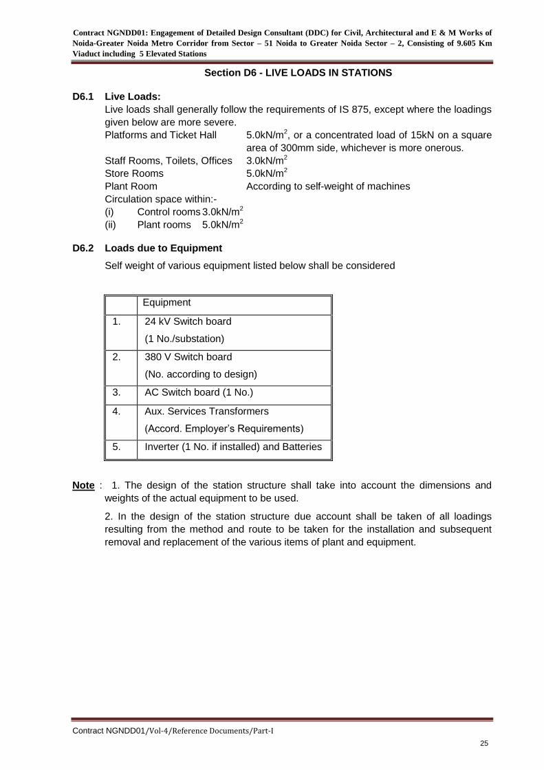
D6.2 Loads due to Equipment
Self weight of various equipment listed below shall be considered
Equipment
1. 24 kV Switch board
(1 No./substation)
2. 380 V Switch board
(No. according to design)
3. AC Switch board (1 No.)
4. Aux. Services Transformers
(Accord. Employer’s Requirements)
5. Inverter (1 No. if installed) and Batteries
Note : 1. The design of the station structure shall take into account the dimensions and
weights of the actual equipment to be used.
2. In the design of the station structure due account shall be taken of all loadings
resulting from the method and route to be taken for the installation and subsequent
removal and replacement of the various items of plant and equipment.
Contract NGNDD01: Engagement of Detailed Design Consultant (DDC) for Civil, Architectural and E & M Works of
Noida-Greater Noida Metro Corridor from Sector – 51 Noida to Greater Noida Sector – 2, Consisting of 9.605 Km
Viaduct including 5 Elevated Stations
Contract NGNDD01/Vol-4/Reference Documents/Part-I
26
Section D7 - ELEVATED STRUCTURES
STRUCTURAL SYSTEM AND ARTICULATION
D7.1 General
Viaducts and bridges form the predominant components of the NMRC’S on the Rail
Corridor. The form, dimensions and design requires special consideration to resolve
structural suitability, economy and aesthetics concerns. Viaducts for the corridor shall
be generally twin C girder system, having all the required support system for cabling,
OHE and the railway tracks, is the economical solution under normal circumstances.
Consideration shall be given to include in the design the following requirements:
Long welded rails with track centres at 4.60m and suitable for kinematic profile of
Standard Gauge schedule of dimensions of NMRC.
The track shall be ballastless construction on the elevated segments
D7.2 Railway Requirements
D7.2.1 Provision for emergency evacuation shall be provided along the railway for the full
length of the structure. Routes assigned for emergency evacuation shall be designed
for footway loading in accordance with the requirements stated herein.
D7.2.2 The DDC shall note that there is a requirement to provide touch potential protection to
passengers on the platforms. The design shall therefore include for a width of 2.5
metres from the platform edge to be insulated from ground earth by insertion of PVC
and/or other insulating compounds. Metalwork railings etc. shall be kept a minimum of
2.5 metres from the platform edge unless similarly insulated.
D7.2.3 Parapets
Parapets shall be provided on both sides of all viaducts for the full length of the
structure. They shall be designed to act as the support structure to the railway cabling
as appropriate. Parapets shall be designed to resist a horizontal and a vertical force
each of 150kg/m applied simultaneously to the top of railing or parapet
Parapets shall be provided for all transition structures to protect the guideway from
intrusion by trespassers, vandals and road vehicles.
Parapets shall be designed to function as Noise Containment Barriers.
Parapets shall be designed to cater the forces of OHE (if any).
D7.3 Vertical Alignment
D7.3.1 Profile grade:
The superstructure shall be so designed that, when subject to dead load only, the rail
level would be above the theoretical vertical profile of the system by an amount equal
to permissible LL deflection for the structure.
Provision for super-elevation shall be made preferably as part of the track structure
over the deck. The dead load is to be considered at such locations.
D7.3.2 Camber
The superstructure deck, including the soffit of any overhead structure above the deck,
Contract NGNDD01: Engagement of Detailed Design Consultant (DDC) for Civil, Architectural and E & M Works of
Noida-Greater Noida Metro Corridor from Sector – 51 Noida to Greater Noida Sector – 2, Consisting of 9.605 Km
Viaduct including 5 Elevated Stations
Contract NGNDD01/Vol-4/Reference Documents/Part-I
27
shall be cambered so as to compensate for the combined effect of:
vertical curvature, if any;
dead load deflection; and
permissible live load plus-impact deflection as accepted by the Employer’s
Representative.
D7.3.3 Span/Depth ratios
Length-to-depth ratio should as far as possible be restricted to:
Reinforced concrete member- 10
Pre-stressed concrete member:
Composite members - 16- Desirable 12
In Box girders these ratios shall be further subject to stipulations made with regard to
internal dimensions required for inspection and future pre-stressing.
Desirable Minimum thickness of any RC member
Deck - 200 mm
Web of T-beam - 250 mm
Web of prestressed girders - 150 + d
If there are 2 cables at any level - 150+3d
(where d is the diameter of the cable duct.)
Box Girders: minimum member thickness:
Deck slab - 200 mm
Bottom flange - 300 mm
Web - 250 mm
or as required by IRS Concrete Bridge Code whichever is the greater thickness
In an aggressive environment, an additional thickness of 10 to 20 mm shall be used.
D7.3.4 Typical pier locations are shown on the drawings. Where topographical or service
utility restraints dictate use of longer/continuous spans, pier locations may be adjusted
to suit the proposed span lengths.
D7.3.4.1 The Consultant shall provide, by suitable choice of span lengths, a sufficiently stiff
deck and supporting sub-structure to resist loading as defined in Clauses D5.1 to
D5.8 above. Static and dynamic rail live load responses, at essential movement joint
locations, shall be in compliance with the Employer’s Requirements.
D7.3.4.2 Halving joints shall not be used unless absolutely essential.
D7.3.4.3 The design of the Permanent Works shall comply with the railway noise requirements
detailed in Clause D5.11.
D7.3.4.4 Rail/Structural interaction analysis due to continuous welded rail with direct fixation or
structure shall be performed in accordance with proven international practice.
D7.3.4.5 Approach slabs of sufficient sizes shall be provided between abutments and at-grade
sections.
Contract NGNDD01: Engagement of Detailed Design Consultant (DDC) for Civil, Architectural and E & M Works of
Noida-Greater Noida Metro Corridor from Sector – 51 Noida to Greater Noida Sector – 2, Consisting of 9.605 Km
Viaduct including 5 Elevated Stations
Contract NGNDD01/Vol-4/Reference Documents/Part-I
28
An approach slab shall be provided in rear of all abutment of elevated structures and
bridges. This should not be less than 6 m in length nor be less than the length
computed from the formula:
L = 1.5 h tan(45o – Ø/2)
Where h = Depth from bottom of slab to bottom of abutment (top of footing)
Ø = Angle of internal friction of backfill soil in degrees
Slab shall be designed assuming that it does not receive any support from the backfill
for a distance of not less than 4.0 m nor less than h tan(45o - Ø/2) from back of
abutment.
D7.4 Design Considerations
D7.4.1 Vibration and Deflection Limitations
The amplitude and frequency of vibrations of the viaduct and station structure shall be
limited to international standards.
The overall deflection as specified elsewhere in the contract for elevated structure will
be limited taking into consideration the effect of vibration in addition to other
considerations.
Suitable provisions shall be provided at the ends of beams and jacking pads on pier
caps shall be provided to allow for replacement of bearings and for any repairs during
service.
Provision should be made for adequate fixtures of the superstructure to the
substructure, if any loading or loading combination increased by 100% of live load plus
impact is likely to cause uplift of any support.
D7.4.2 Design Procedures
Reinforced and Pre-stressed concrete members of elevated structures shall be
designed in conformity with the provisions of IRS and IRC Codes.
D7.4.3 Method of Construction
Stresses in partially completed structures shall be analysed for appropriate critical
conditions at various stages of the construction.
Any restriction on the construction operations resulting from the design assumptions
shall be clearly specified on the contract drawings and specifications. Conversely,
advantage may be taken by the designer of specified construction procedures or
sequences to effect a more favourable distribution of loads or stresses.
D7.4.4 Movement/Expansion Joints
Movement/expansion joints and other necessary measures to control shrinkage and
thermal effects shall be incorporated in the structural design so that the performance of
architectural finishes or of any services are not adversely affected during normal
working conditions.
Movement/expansion joints shall be designed to be easily maintained and replaceable.
D7.4.5 Design Surface Crack Width
Contract NGNDD01: Engagement of Detailed Design Consultant (DDC) for Civil, Architectural and E & M Works of
Noida-Greater Noida Metro Corridor from Sector – 51 Noida to Greater Noida Sector – 2, Consisting of 9.605 Km
Viaduct including 5 Elevated Stations
Contract NGNDD01/Vol-4/Reference Documents/Part-I
29
For the serviceability limit state of cracking:
Design surface crack width of reinforced concrete viaduct structures shall not
exceed the values given in Table 10 of CBC-1997 (Correction slip No.1 dated
26.04.2000).
Pre-stressed concrete viaduct structures shall be designed as per provisions of
IRS and IRC Codes.
Design surface crack width of reinforced concrete station structures exposed to
weather shall not exceed the values given in Table 10 of CBC-1997 (Correction
slip No.1 dated 26.04.2000).
Pre-stressed concrete station structures that are exposed to the weather shall be
designed as per IRS/IRC or other relevant codes. Structural elements that are
fully protected from the weather may be designed as class 2.
All aqueous liquid retaining structures and basements shall be designed to the
requirements of BS 8007 unless otherwise varied by this specification.
D7.4.6 Temperature Effects
Temperature effects shall be taken into account in accordance with the requirements
of IRS or BIS, where applicable.
The difference between maximum and minimum effective temperature shall be taken
as 35°C.
D7.4.7 Not Used.
D7.4.8 Structural Members with Bearings
Consideration shall be given for the easy maintenance and replacement of viaduct and
station bearings.
The minimum clearance between structural members separated by bearings shall be
as follows:
Precast Viaduct Beam/Cross Head : 150 mm
In-Situ Viaduct Beam/Column : 250 mm
Precast station Beam/Corbel : 175 mm
These are absolute minimum values and the requirement for easy maintenance and
replacement of bearings shall prevail.
D7.4.9 Thermal Rail Forces
Provision shall be made for horizontal transverse and longitudinal forces due to
temperature variation in rail. The forces shall be applied in a horizontal plane at the
top of low rail as follows:
(1) Transverse Force. The transverse force (T) per linear metre of structure
per rail shall be determined by the following formula:
T = 650 kN
R
Contract NGNDD01: Engagement of Detailed Design Consultant (DDC) for Civil, Architectural and E & M Works of
Noida-Greater Noida Metro Corridor from Sector – 51 Noida to Greater Noida Sector – 2, Consisting of 9.605 Km
Viaduct including 5 Elevated Stations
Contract NGNDD01/Vol-4/Reference Documents/Part-I
30
Where; R = radius of rail curvature in metres.
(2) Longitudinal Force. A longitudinal force shall be applied in accordance
with Indian Standards.
D7.4.10 Access To Voids
Continuous access between the deck voids shall be provided wherever possible. An
easily removable, watertight manhole access to deck voids shall be provided in every
span.
D7.4.11 Pre-stressed Concrete
Non-shrink grout shall be used for grouting of post-tensioned tendon ducts.
Pre-stressing anchorages shall be detailed such that they are easily accessible for
inspection and maintenance. The detailing shall also prevent the accumulation of
water and dirt around the anchorage.
All assumptions made in the determination of the design pre-stress loads, e.g.
curvature, friction, cross section and mechanical properties of strand and concrete
shall be clearly stated on the drawings.
D7.4.12 Bearings
D7.4.12.1 In the selection of the bearing layout in viaducts and elevated stations,
consideration shall be given to their performance in relation to the supporting
structures, economy as well as maintenance and replacement of the bearings.
D74.12.2 Due care must be taken to ensure that no pair of bearings act against one
another in service conditions to the detriment of the structure and to the bearings
themselves.
A suitable bearing layout for the viaduct could be the 3-bearing system.
D7.4.12.3 Design Life
Bearings and their installations shall be designed to be compatible with the
design life of the viaduct and the elevated stations.
Whenever the expected design life of the bearings is significantly less than that
of the structure, provision shall be made for the removal and replacement of the
whole or parts of the bearings.
D74.12.4 Type of Bearings
Bearings for the viaducts would preferably be Elastomeric Bearings, but types
used by NMRC under similar applications will be acceptable.
For the elevated stations, elastomeric bearings or POT/PTFE would be
acceptable. Where necessary and with the Engineer’s prior acceptance,
vibration-reducing bearings shall be specified for the elevated stations.
The type of bearings and their installations to be adopted shall be such that they
satisfy the requirements for their design life as stipulated in IRC-83 or UIC-772R.
D7.4.12.5 Bearing Design
Unless otherwise specified, bearings shall be designed in accordance with the
requirements of IRC Codes or UIC.772R.
Contract NGNDD01: Engagement of Detailed Design Consultant (DDC) for Civil, Architectural and E & M Works of
Noida-Greater Noida Metro Corridor from Sector – 51 Noida to Greater Noida Sector – 2, Consisting of 9.605 Km
Viaduct including 5 Elevated Stations
Contract NGNDD01/Vol-4/Reference Documents/Part-I
31
Bearings for viaducts and elevated stations shall be designed to allow for the
following movements:
Thermal expansion and contraction: An ambient range varying
between 2°C to 47 °C should be considered for Noida-Greater Noida
Shrinkage of concrete
Creep in concrete
Elastic shortening under prestress
Displacements of structure under load:
Differential settlement between viaduct piers shall be considered.
Rotation and sway of columns and crossheads under the worst
load combination including the effects of temporary loads during
construction shall be considered.
Schedule listing the performance requirements for each type of bearings for
viaduct and elevated stations shall be incorporated in the drawings. The
schedule shall indicate the following:
Dead load to be supported (SLS and ULS)
Maximum and minimum vertical live load to be supported (SLS and
ULS)
Horizontal forces to be resisted (SLS and ULS)
Rotation capacity required
Translation capacity required (both reversible and irreversible). In the
case of in-situ viaducts, the amount of pre-setting required for the
bearings should be clearly indicated.
Calculations for movements of bearings shall take into account the variability of
materials and conditions that the structure is expected to encounter during its
design life.
In the above ULS and SLS mean Ultimate Limit State and Serviceability Limit
State respectively as defined by IRS Concrete Bridge Code-1997.
Design of the bearings, derailment loads requirements specified in IRS Bridge
Rules shall be taken into consideration. The corresponding viaduct rotation
under derailment loads shall be controlled to minimise damage to the viaduct
elements.
In the design of the bearings to resist lateral loads, friction between the bearing
and mortar shall be ignored.
Mortar bedding composing of sand and either cement, polyester resin or epoxy
resin shall have a crushing strength of at least twice the average contact stress.
In the choice of bedding due consideration shall be given to the future removal
and replacement of the bearing without damage to bedding or to the structural
elements bonded to it.
Shear studs or bolts shall be provided to secure the bearing top and bottom
plates to the structure. The shear studs or bolts shall be designed in accordance
Contract NGNDD01: Engagement of Detailed Design Consultant (DDC) for Civil, Architectural and E & M Works of
Noida-Greater Noida Metro Corridor from Sector – 51 Noida to Greater Noida Sector – 2, Consisting of 9.605 Km
Viaduct including 5 Elevated Stations
Contract NGNDD01/Vol-4/Reference Documents/Part-I
32
with international practice.
The fixing method to be adopted shall be such that it is convenient and possible
to replace the bearings at some future date.
The designer shall ensure that the bearings can be produced to satisfy the
design requirements; and that the space allowed for in the overall design is
sufficient to accommodate the bearings and enable them to be inspected,
maintained and replaced when required.
D7.5 Highway Clearances
The vertical and horizontal highway clearances required to structures shall generally
be in accordance with the requirements described below.
D7.5.1 Vertical Clearances
The minimum clearance between the elevated structures and highways, railways,
utility lines and other structures and property should be greater by a minimum of 250
mm on those prescribed by the agencies involved. The minimum vertical clearance
below the bottom of the structure for any highway/road passing below will be 5.5
metres as prevailing presently. In case of minor roads/streets a lower clearance may
be adopted with specific approval of the agency owning and/or maintaining the
road/street.
D7.5.2 Horizontal Clearances
The clear span over the roads passing below the viaduct/bridge shall be determined
after evaluation of present and future needs.
Protection shall be necessary for piers against accidental impact from road vehicles on
a case by case basis. IRC-6-2000 shall be applied.
For supports located in the median or adjoining major roads where heavy goods
vehicles pass at high speed and where adequate clearances are not available, the
foundations and piers shall be designed for an impact force of 100t at a height of 1.2 m
above road level in the direction of traffic. Higher permissible stresses shall be
considered. The approach to the pier shall also be protected by non-mountable kerb
and sand filling.
Where clearances are available and a suitably designed safety barrier can be
provided, the pier shall not be checked for 100t impact force. The protection afforded
should be such that when a car of 1.5t weight strikes the barrier at 110 kph and at an
angle of 20o, the wheels of the car will only just reach the pier. The clearance between
the pier and safety barrier shall be 0.6 m or more, and the safety barrier shall be a
guardrail or crash barrier, mounted on posts to form a free standing rail barrier.
D7.6 Viaduct Deck Furniture, Drainage and Waterproofing
Viaduct deck furniture, drainage and waterproofing system shall be designed for all
effects and requirements of the railway as per IRS/IRC Codes.
Cast-in drains shall be used, provided with rodding eyes at every bend. Runoff on
viaduct structures and bridges shall be collected through surface drains that shall lead
to down drains at the support columns. The down drains shall be connected to a
drainage system which shall consist of collection header pipe and manholes which
shall discharge to the nearest suitable drainage system. Silt removal shall be provided

Contract NGNDD01: Engagement of Detailed Design Consultant (DDC) for Civil, Architectural and E & M Works of
Noida-Greater Noida Metro Corridor from Sector – 51 Noida to Greater Noida Sector – 2, Consisting of 9.605 Km
Viaduct including 5 Elevated Stations
Contract NGNDD01/Vol-4/Reference Documents/Part-I
33
where necessary.
D7.7 System wide Requirements
D7.7.1 Systemwide requirements must be considered in the development of the structural
design. Such consideration shall include:
The incorporation of a stray current corrosion control system
The incorporation of an adequate water drainage system
The necessary design of reinforcement in plinth and deck so as to avoid interference
with and attenuation of the signalling circuits
Special care taken with the location of gullies in points and crossing areas.
Provision for future pre-stressing of cable/strands as per IRS code shall be made for
all pre-stressed concrete members (External pre-stressing) as indicated in the
conceptual drawings.
D7.7.2 Systemwide details are liable to changes as the requirements of various contracts
become known and their designs are developed. The DDC shall be responsible for
incorporating all Systemwide requirements as they become available.
D7.7.3 All details provided to meet Systemwide requirements shall be subject to the
acceptance by the Employer’s Representative.