Embed Size (px)
Citation preview
I^RolandBEBUNEAR SYNTHESIZER
Owner's ManualAdvancedMIDI ImplementationD-50 Edit MapD-50 Sound Chart
A A AA
The lightning flashwith arrowhead symbol, within an equilateral
triangle, is interxJed to alert the user to the presence ol un-
insulated "dangerous voltage" within the product's endosurethat may be of suHicient magnitude to constitute a risk of
electric shock to persons.
The exclamation point within an equilateral triangle is intended
to alert the user tc the presence ol important operating andmaintenance (servicing) inslruclions in the literature accom-panying the product.
I
INSTRUCTIONS PERTAINING TO A RISK OF FIRE. ELECTRIC SHOCK OR INJURY TO PERSONS-
1
IMPORTANT SAFETY INSTRUCTIONSWARNING When using electric products, basic precau-
tions should always be Idlowed, including
theloHowing:
1. Read all the insinjdions belore using the product.
2. Do not use this product near water- lor example,near a bathtub, washbowl, kitchen sink, in a wetbasement, or near a swimming pod. or the like.
3. This product shoukJ be used only with a cart or
stand that is recommended by the manulacture.
4. This product, either atone or in combination with anamplifier and headphones or speakers, may becapat>le ol producing sound levels that could causepennanent hearirtg toss.
Do not operate for a tong period of lime at a high
volume level or at level that is uncomfortable. If youexperience any heanng toss or tinging in the ears,
you shoukl consult an audiok^gist,
5. The product shoukJ be located so that rts kwaiion or
position does not interlere with its proper ventilation.
6. TTie product shouki be tocaied away from heal
sources such as radiators, heat registers or oiher
products thai produce heal.
7. The product should avoid using in where it may t*effected Oy dusl.
8. The product sboukJ be connected to a power supplyonly of the type descrit>ed in the operaSng insiOJC-
ttons or as marked on the product.
9. The power-supply cord of the product should beunplugged Irom the outlet when left unused lor atorig period of time.
10. Do not l/ead on the power-supply cord.
11. Do not pull the cord but hold the plug whenunplugging.
12. When setting up with any other msirumenls, the
procedure should be followed m accordance with
instnjction manual.
13. Care shoukl be taken so that objects do not fall andliquids are not spilled into the enctosure througbopenings.
14. The product ShoukJ be serviced by qualified servicepersonnel when:
A: The power-supply cord or the plug has beendamaged; or
B: Objects have taiien, or iiqukJ has been spilled
into the product; or
C: The product has been exposed to rain: or
D: The product does not appear to operatenormally or exhibits a mari(ed change in perfor-
mance: or
E: The product has been dropped, or the enclosuredamaged.
15. Do not attempt to service the product beyond that
described in the user-maintenance instructions. All
otherservicingshoukJbereferredtoqualified servcepersonnel.
SAVE THESE INSTRUCTIONS
ADVARSEL!
Lithiumbatteri. Eksplosionsfare,
UdskHtning mS kun foretages af en sagkyndig,
og som beskrevet i servicemanual.
VARNING
!
Lithiumbatteri. Explosionsrisk.
Far endast bytas av behorig servicetekniker.
Se instmktioner i servicemanualen.
ADVARSEL!
Lithiumbatteri. Fare for eksplotion.
Ma bare skiftes av kvalifisert tekniker som
beskrevet i servicemanualen.
VAROITUS!
Lithiumparisto. Rajahdysvaara.
Pariston saa vaihtaa ainoastaan
alan ammottimies.
WARNINGTHIS APPARATUS MUST BE EARTH GROUNDED.
The three conductors of the mainslead attached to this apparatus are
identified with color as shown in thetable below, together with the
matching terminal on the UK typepower plug. When connecting themains lead to a plug, be sure loconnect each conductor to the cor-
rect terminal, as indicated.
"This instfuction applies to theproduct for United Kingdom."
MAINS LEADS PLUG
Conductor Color Mark on the matching leiminal
Live Brown Red or letter L
Neutral Blue Stack or letter N
Grounding Green-
Yellow
Green. Green-Yellow, letter E
or symtKil
.—.^^
B«chaini9ung des Herstellers /Importeurs
Hictmil wird beschtinigl, daQ dci/dic/dai
ROLAND LINEAR SYNTHESIZER 0-50CG^fai. '»p B*rK*H*MAfll
in Utwrcinjiimmung m-I den Sesiimmungeri der
Amtsbl. Vfg 1046 / 1984
lunk-eniiio-t ist,
Dti DtutKtMn Sundtspoil wurde d»s Inverkehibungen dieiej Geraleiengeicigt und ait Serechligung lui Ubcrprulung Qtt Stnt auf Einhaliungder Beslimmungen eingeraumT.
Roland Corporation Osaka / Japan
RADIO AND TELEVISION INTERFERENCE
Please read the separate volume "MIDI", before reading this owner's manual.
Copyright © 1987 by ROLAND CORPORATIONAll rights reserved. No part of this publication may be reproduced in
any form without the written permission of ROLAND CORPORATION
.
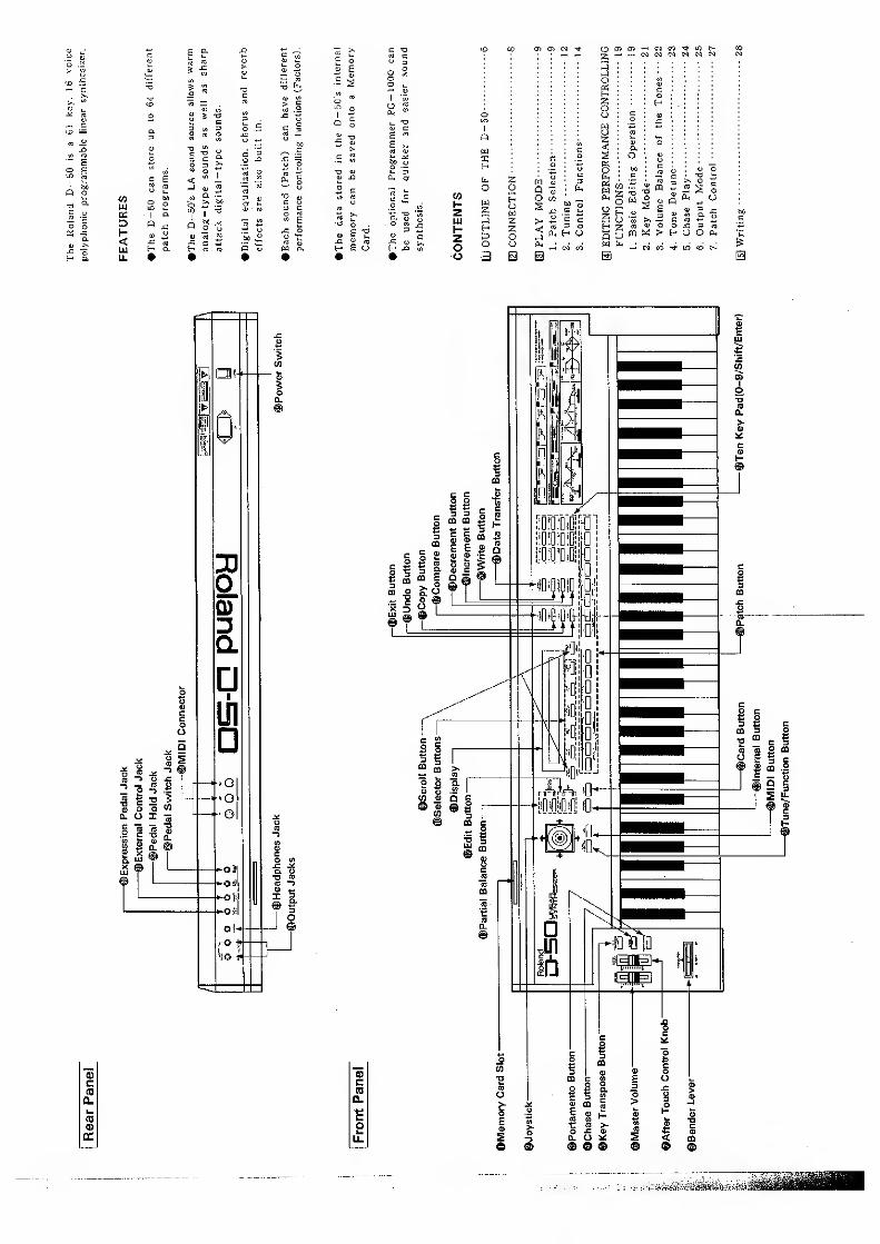
ft o
<LL
3
01 01 M -^f
a
O w^ .S i;
P. U
O m 01
2 - -
O«
o
o «
o «
Q p
B
aj O o J3 = ni
CQ M > t- U O—' M P7 in to

IMPORTANT NOTES
Power
•The appropriate power supply for this
unit is shown on Its name plate. Please
make sure that the line voltage in your
country meets the requirement.
•Please do not use the same socket used
for any noise generating device (such
as a motor or variable lighting system.)
•This unit might not work properly if
turned on immediately after being turned
off. If this happens, simply turn it off
and turn it on again after waiting a
few seconds.
•It Is normal for this unit to become
hot while being operated.
•Before setting up this unit with other
devices, turn this unit and all the other
units off.
•When disconnecting the power plug from
the socket, do not pull the cord but
hold the plug to avoid damaging the
cord.
•If the unit is not to be used for a long
period of time, unplug the cord from
the socket.
•Operating this device near a neon or
fluorescent lamp may cause noise
interference. If so, change the angle or
the position of the device.
•Avoid using this device in extreme heat,
humidity or where it may be affected
by dust or vibration.
•Use a mild detergent for cleaning. Donot use solvents such as thinner.
•The D — 50 features a memory back — upsystem that retains the data even whenswitched off. The battery that supports
the back-up circuit should be replaced
every five years. Call Roland for battery
replacement.CThe first replacement maybe required before five years, depending
on how much time had passed before
you purchased the device.
•To avoid accidental erasure or loss of
data, please make a data memo, or save
the data onto a Memory Card. If It happens
to be erased while the device is being
repaired, there is no way to restore the
data.
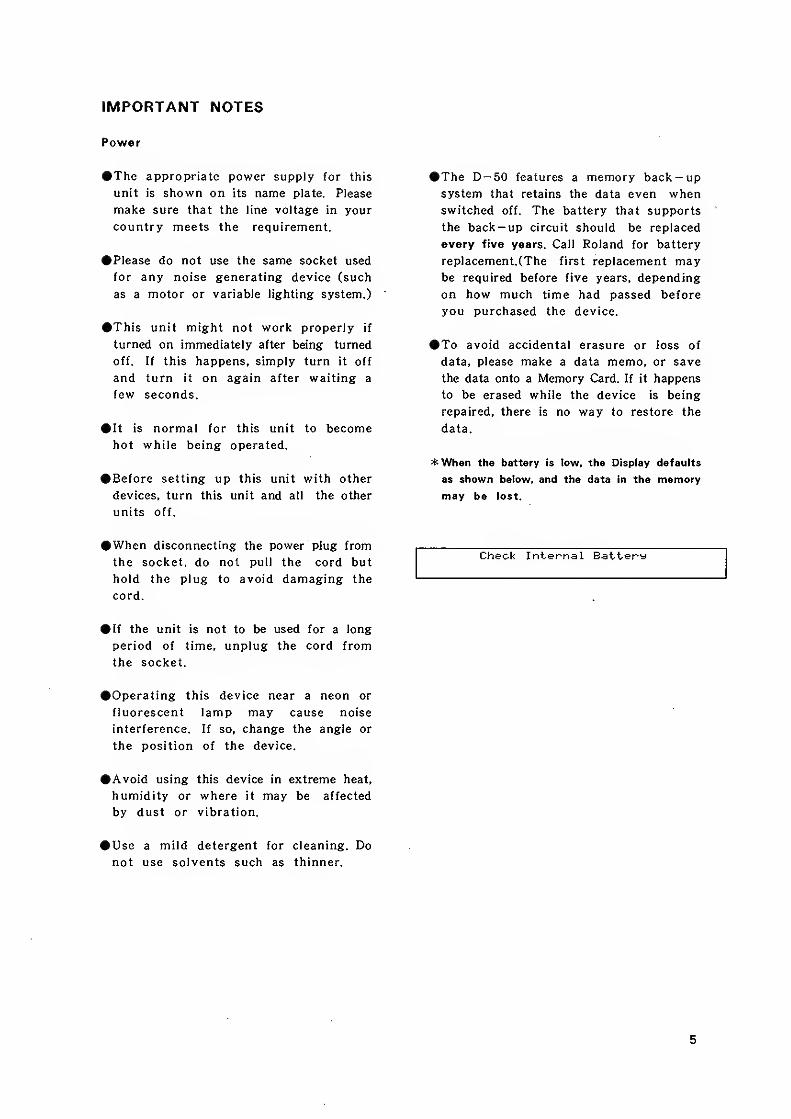
*When the battery is tow, the Display defaults
as shown below, and the data in the memory
may be lost.
Check Internal Battery
5
OUTLINE OF THE D-50
[U OUTLINE OF THE D-50
The ROLAND D-50 is very different from any other synthesizer,
past or present, and as such heralds the dawn of a new era in
synthesis. In the past, synthesizers have progressed through several
very diffrent stages. Firstly, there were ANALOG synthesizers, which
relied on a variety of components, such as, VCO's, VCF's. and
VGA's. These analog building blocks were relatively easy to
understand and program, and they could produce sounds of
remarkable warmth and character. However, when it came to
accurately simulating acoustic sounds, the process could easily
become too involved.
On the other hand, the next breed of synthesizers, known as
DIGITAL synthesizers, could easily simulate acoustic sounds, yet they
were far more difficult to program. Furthermore, the digital
technology behind these instruments seemed to imply that a
different type of sound should occur. In general, just as an analog
synthesizer would be described as "warm", in character, the digital
counterpart was very often "thin". Essentially, the two types
complemented each other, one being easy to program, the other
capable of accurate simulation.
The ROLAND D-50 has now changed all that. Thanks to a newcustom disigned Integrated Circuit known as the 'LA CHIP'. Here,
LA stands for Linear Arithmetic synthesis which is the heart of the
new technology. LA synthesis involves a great many technological
advances resulting not only in a superior sound quality but also an
improved ease of programming. In this way, Roland has succeeded
in maintaining a high degree of familiarity to the user despite the
technical wizardry involved.
To explain the D—50 in a very simple manner, we must begin by
saying that it is the next step in DIGITAL synthesizers. This meansthat the sound is entirely computer generated. In fact, the D— 50
has four distinct sections :
1. A Digital Synthesizer
2. A Digital Equalizer
3. A Digital Chorus section
and 4. A Digital Reverberation section.
Moreover, these four sections occur entirely within the DIGITALDOMAIN, resulting in a sound quality far beyond that of four similar
units combined. Consequently, the musician can take advantage of
a complete instrument, one that requires no additional effects or
processing.
However, the true power of LA Synthesis lies within the Digital
Synthesizer section of the D— 50. Remember, first of all, that this is
a totally digital instrument, even though the sound would seem to
suggest far more. Through LA synthesis, the D— 50 appears to have
four powerful synthesizers built in. Each of these hypothetical
synthesizers could behave like a conventional analog syntheizer, or
a PCM sampled synthesizer. Consequently, they are referred to as
PARTIALS, since they are far more than just a pure synthesizer.
These Partials are combined in pairs to form a TONE. A Tone could
either be a mix of the two Partials, or they could take advantage
of the LA version of cross modulation. In this way, some of
today's more popular digital sounds are remarkably easy to achieve.
6
OUTLINE OF THE D-50
Patch[ Tona Tunina
]
Uppoi' Tone
Kay ModeVaiialions of
Control Functions
Volume Balance
oi Tones
Output Mode
(e.g. Revefb)
> Lower Tone
I
Tone Tuning
Tone
Ptnat 2
Structure J[env fof pilch control]
Common
3 LFO"s D
Equalizer
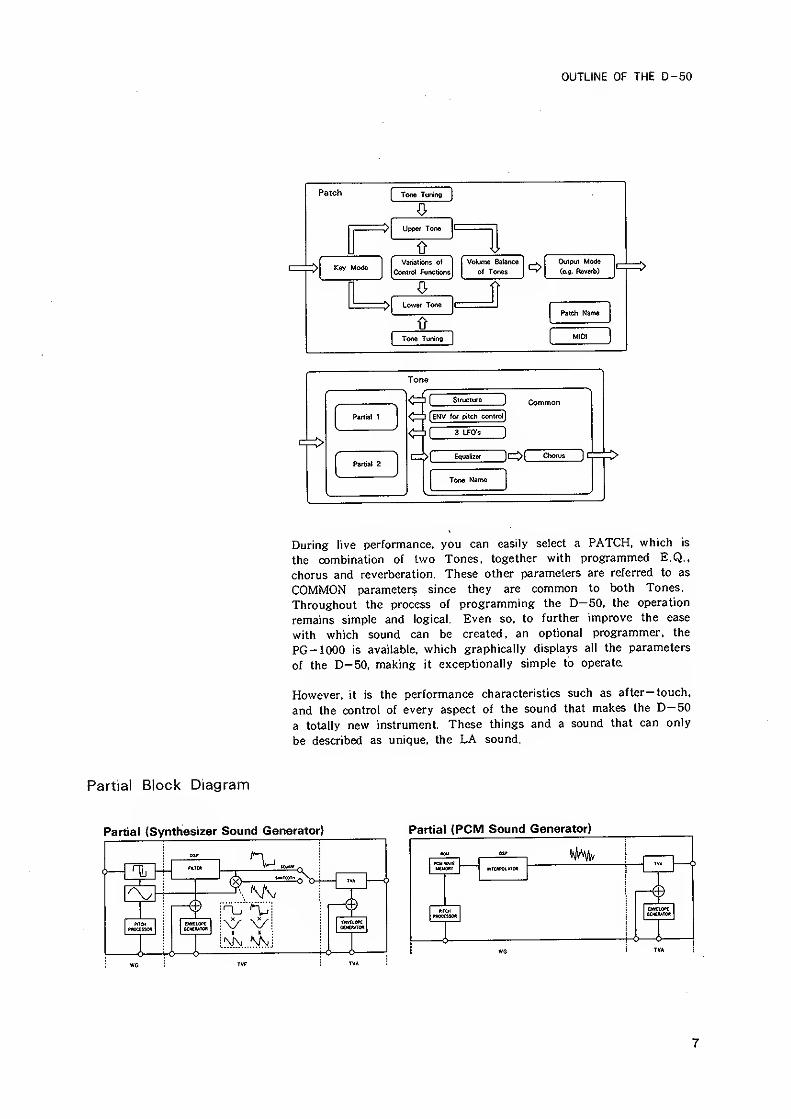
During live performance, you can easily select a PATCH, which Is
the combination of two Tones, together with programmed E.Q..
chorus and reverberation. These other parameters are referred to as
COMMON parameters since they are common to both Tones.
Throughout the process of programming the D— 50, the operation
remains simple and logical. Even so, to further improve the ease
with which sound can be created, an optional programmer, the
PC -1000 is available, which graphically displays all the parameters
of the D-50, making it exceptionally simple to operate.
However, it is the performance characteristics such as after-touch,
and the control of every aspect of the sound that makes the D-50
a totally new instrument. These things and a sound that can only
be described as unique, the LA sound.
Partial Block Diagram
Partial (Synthesizer Sound Generator) Partial {PCM Sound Generator)
-
TV. iKMilCu
n
IMt,
—,—
,
0*T nTCRPOLHOIt
4UHUtTOD
yW5
7
CONNECTION
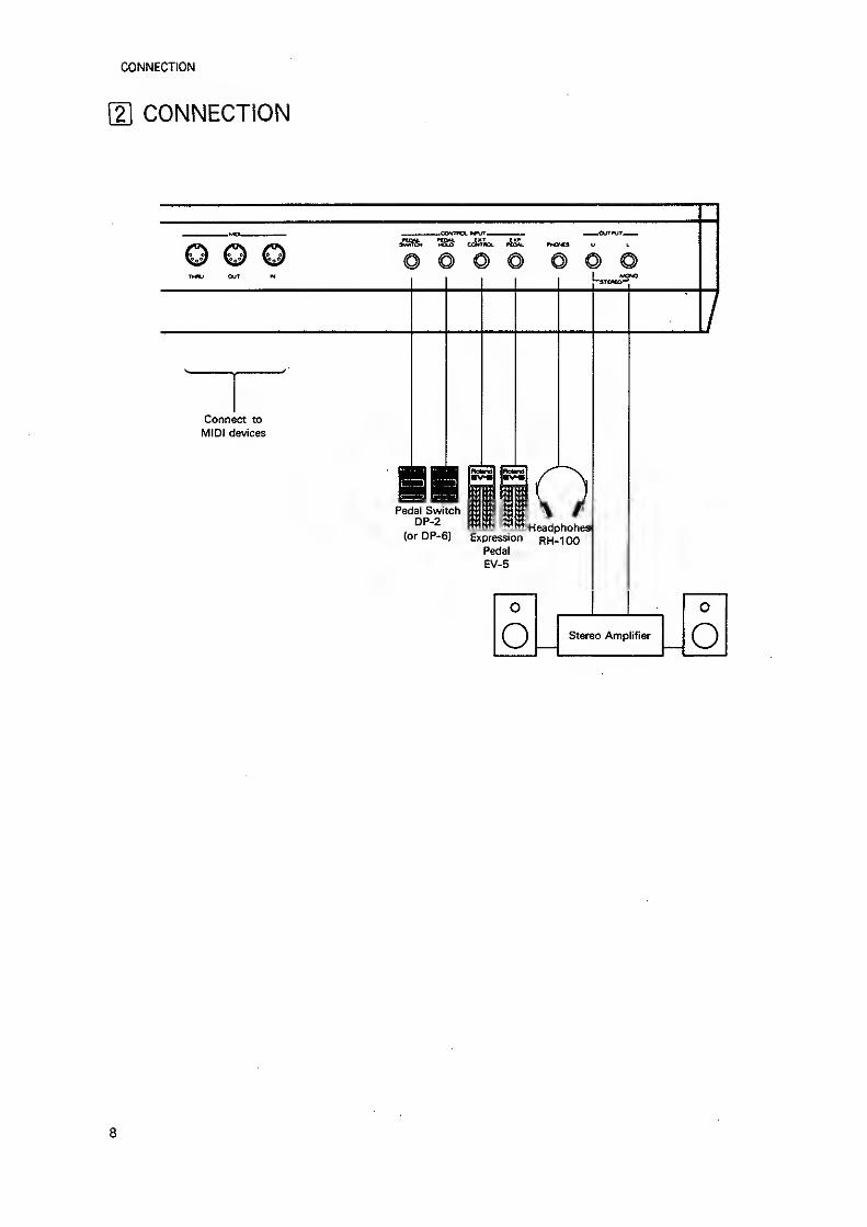
{2\ CONNECTION
tuv Out
ftOM. tj
Connect to
MIDI devices
ofHeadphohes
Pedal SwitchDP-2
(or DP-6) Expression p^-l 00Pedal
EV-5
o_ Stereo Amplifier o
8
PLAY MODE
3 PLAY MODE
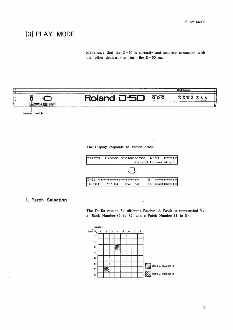
Make sure that the D--50 is correctly and securely connected with
the other devices, then turn the D-50 on.
E} <> Roland n-SC o o o o o o1—IT
\ c
Power Switch
The Display responds as shown below.
4:>f:>f:>f:>f:4: Lifieaf^ Synt-h&sizep D~50 ******
Roland Corporation
U:
WHOLE £P C4 Bal 50 L:
1 . Patch Selection
The D— 50 retains 64 different Patches. A Patch is represented by
a Bank Number (1 to 8) and a Patch Number (1 to 8).
Number
BanlNv 1 2 3 4 S 6 7 8
i
Bank 3, Number 4
Sank 7. Number 2
9
PLAY MODE
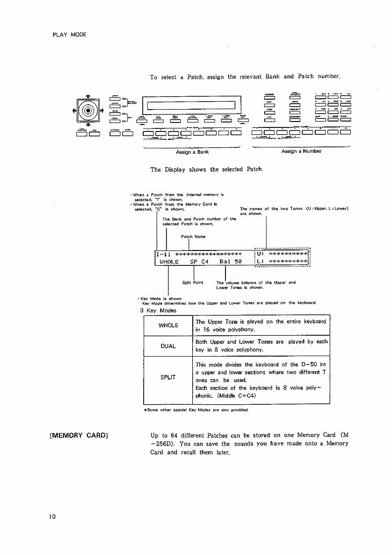
To select a Patch, assign the relevant Bank and Patch number.
1 a"
} f-^ I 1 I—I I—
1
I—I [=Z1
1ZI3IZD CZII==] (ZZ! (ZD C=i CD tZZI llZZllZZilZZCZICZlC
Assign a Bank Assign a Number
The Display shows the selected Patch.
When a Patch from the interna! memory is
selected, 'I" is shown.I When a Patch from the Memory Card is
selected. 'C" is shown.
The Bank and Patch number of the
selected Patch is shown.
The names of the two Tones (U : Ucper, L : Lower)
are shown.
Patch Name
I— 1 1 ******************
WHOLE £P C4 Bal 5©
IJ ; **********l_: M(*********
split Point The volume balance of the Upoer and
Lower Tones is shown.
• Key Mode is shownKey Mode determines how the Upper and Lower Tones are played on the keyboard.
3 Key Modes
WHOLE The Upper Tone is played on the entire keyboard
in 16 voice polyphony.
DUALBoth Upper and Lower Tones are played by each
key in 8 voice polyphony.
SPLIT
This mode divides the keyboard of the D-50 int
o upper and lower sections where two different T
ones can be used.
Each section of the keyboard is 8 voice poly-
phonic. (Middle C=C4)
*Some other special Key Modes are also pro\nded.
[MEMORY CARD] Up to 64 different Patches can be stored on one Memory Card (M
-256D). You can save the sounds you have made onto a Memory
Card and recall them later.
10
PLAY MODE
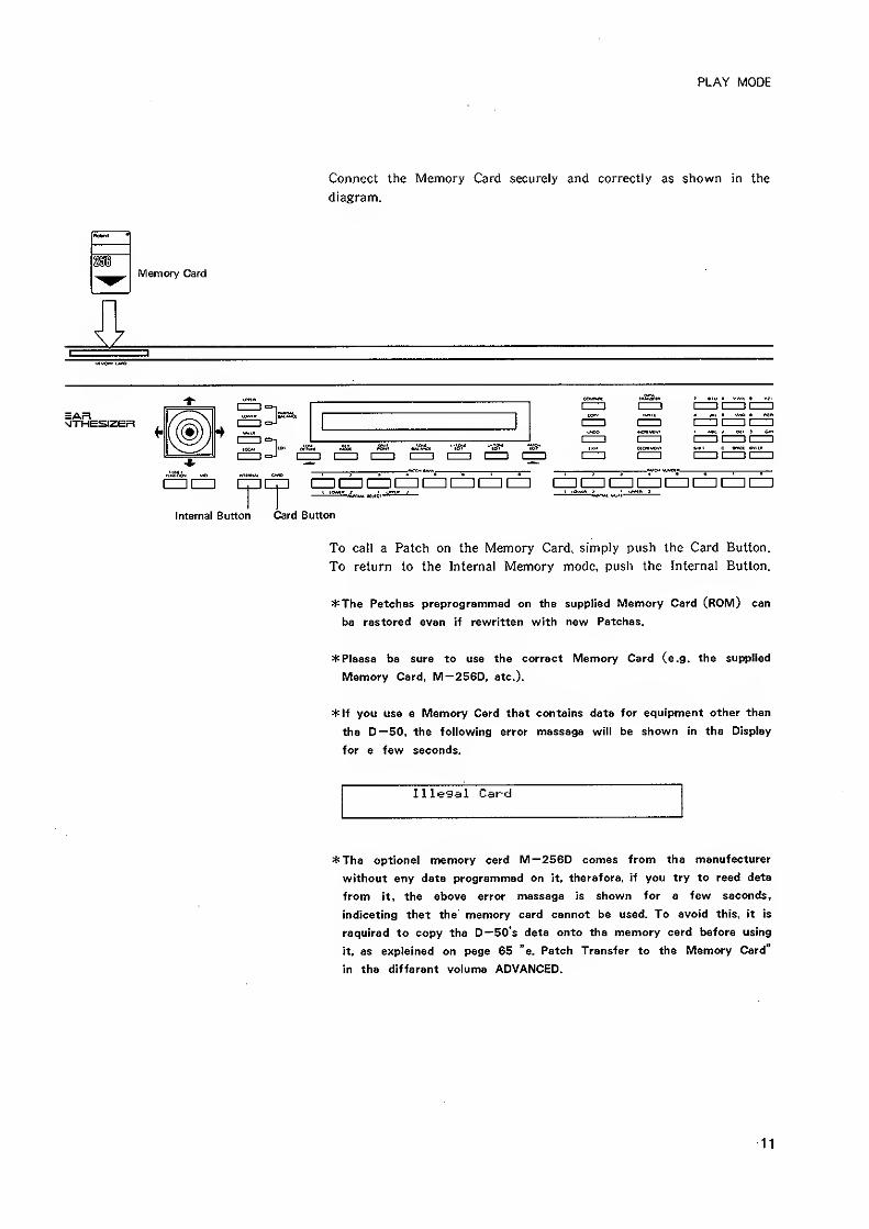
Connect the Memory Card securely and correctly as shown in the
diagram.
Memory Card
EARNlTHESIZER
:> so, %1I II I I [
iZDcn ciDcp cz^a czi cziCD qqa czDcp izzi czi [iz] [zzi
Internal Button Card Button
To call a Patch on the Memory Card, simply push the Card Button.
To return to the Internal Memory mode, push the Internal Button.
*Th6 Patches preprogrammed on the supplied Memory Card (ROM) can
be restored even if rewritten with new Patches.
* Please be sure to use the correct Memory Card (e.g. the supplied
Memory Card, M—256D, etc.).
*lf you use a Memory Card that contains data for equipment other than
the D—50, the following error message will be shown in the Display
for a few seconds.
Illegal Card
*The optional memory card M—256D comes from the manufacturer
without any data programmed on it, therefore, if you try to read data
from it, the above error message is shown for a few seconds,
indicating that the memory card cannot be used. To avoid this, it is
required to copy the D—50's data onto the memory card before using
it, as explained on page 65 "a. Patch Transfer to the Memory Card"
in the different volume ADVANCED.
11
PLAY MODE
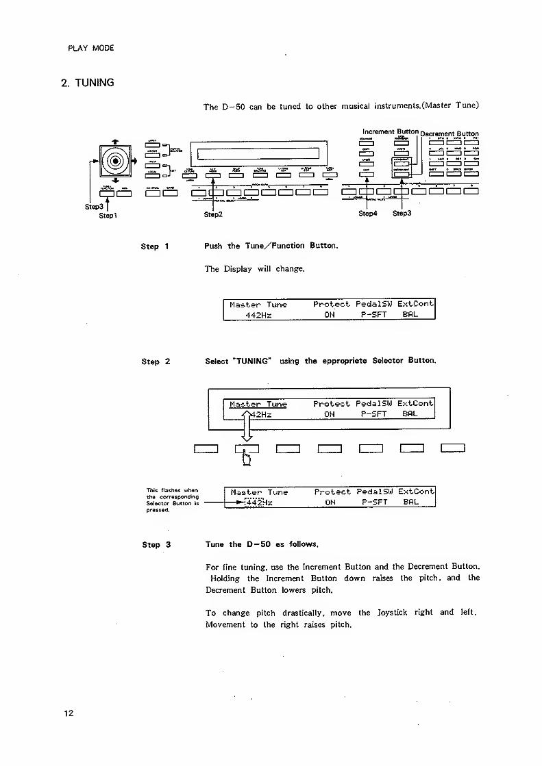
2. TUNING
The D-50 can be tuned to other musical instruments.(Master Tune)
Increment Button ogcrement Button
I—
I
dW, cii. isa ^1
1 r——I I 1 I 1 I 1 [=1 cr, ,
StepsI
Stepi
I I—
I
I—II—11—
I
DCnCZIIZZICIZI
Step2 Step4 Step3
Step 1 Push the Tune/Function Button.
The Display will change.
Master Tune Protect Pedal SW ExtCont
442HS ON P-SFT BPiL
Step 2 Select "TUNING" using the appropriate Selector Button.
Master Tune^2Hz
Protect PedalSW ExtCont
OH P-SFT BfiL
izz: [
This flashes whenthe corresponding
Selector Sutton is
pressed.
Master Tune Protect PedalSW ExtCont—*-f442!Hz ON P-SFT EflL
Step 3 Tune the D-50 as follows.
For fine tuning, use the Increment Button and the Decrement Button,
Holding the Increment Button down raises the pitch, and the
Decrement Button lowers pitch.
To change pitch drastically, move the Joystick right and left.
Movement to the right raises pitch.
12
PLAY MODE
The number shown in the Display is the frequency of the standard
pitch CA=440). The number in the Display changes in IHz steps, but
the pitch actually changes almost continuously.
Step 4 Push the Exit Button, and the Display returns to the normal Play
mode indication.
The Master Tuning you have set is retained in memory even after
the unit is turned off.
13
PLAY MODE
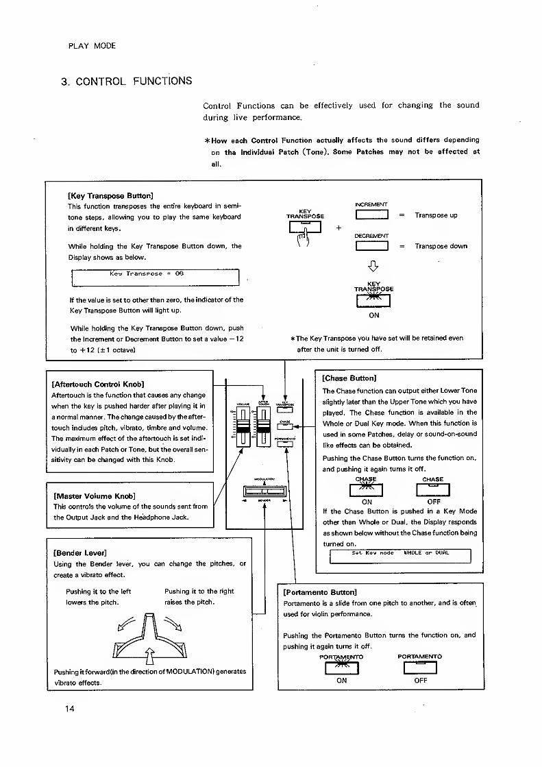
3. CONTROL FUNCTIONS
Control Functions can be effectively used for changing the sound
during live performance.
*How each Control Function actually affects the sound differs depending
on the individual Patch (Tone). Some Patches may not be affected at
all.
[Key Transpose Button]
This function transposes the entire keyboard in semi-
tone steps, allowing you to play the same keyboard
in different keys.
While holding the Key Transpose Button down, the
Display shows as below.
Key Transpose = 00
If the value is set to other than zero, the indicator of the
Key Transpose Button will light up.
While holding the Key Transpose Button down, push
the Increment or Decrement Button to set a value — 1
2
to +12 ( ± 1 octave)
INCREMENT
tranIposeI
I = Transpose up
DECREMENT
\
"] = Transpose down
KEYKEYTRANSPOSE
ON
*The Key Transpose you have set will be retained even
after the unit is turned off.
[Aftertouch Control Knob]
Aftertouch is the function that causes any change
when the key is pushed harder after playing it in
a normal manner. The change caused by the after-
touch includes pitch, vibrato, timbre and volume.
The maximum effect of the aftertouch is set indi-
vidually in each Patch or Tone, but the overall sen-
sitivity can be changed with this Knob.
[Master Volume Knob]
This controls the volume of the sounds sent from
the Output Jack and the Headphone Jack.
=1. 1i
[Bender Lever]
Using the Bender tever, you can change the pitches, or
create a vibrato effect.
Pushing it to the left
lowers the pitch.
Pushing it to the right
raises the pitch.
Pushing itforward{in the direction of MODULATION) generates
vibrato effects.
[Chase Button]
The Chase function can output either Lower Tone
slightly later than the Upper Tone which you have
played. The Chase function is available in the
Whole or Dual Key mode. When this function is
used in some Patches, delay or sound-on-sound
like effects can be obtained.
Pushing the Chase Button turns the function on,
and pushing it again turns it off.
CHASE CHASE
ON OFF
If the Chase Button is pushed in a Key Mode
other than Whole or Dual, the Display responds
as shown below without the Chase function being
turned on.
Set- Key node UHOLE or DUAL
[Portamento Button]
Portamento is a slide from one pitch to another, and is often
used for violin performance.
Pushing the Portamento Button turns the function on, and
pushing it again turns it off.
PORTAMENTO PORTAMEfsrrO
1
^1
ON OFF
14
PLAY MODE
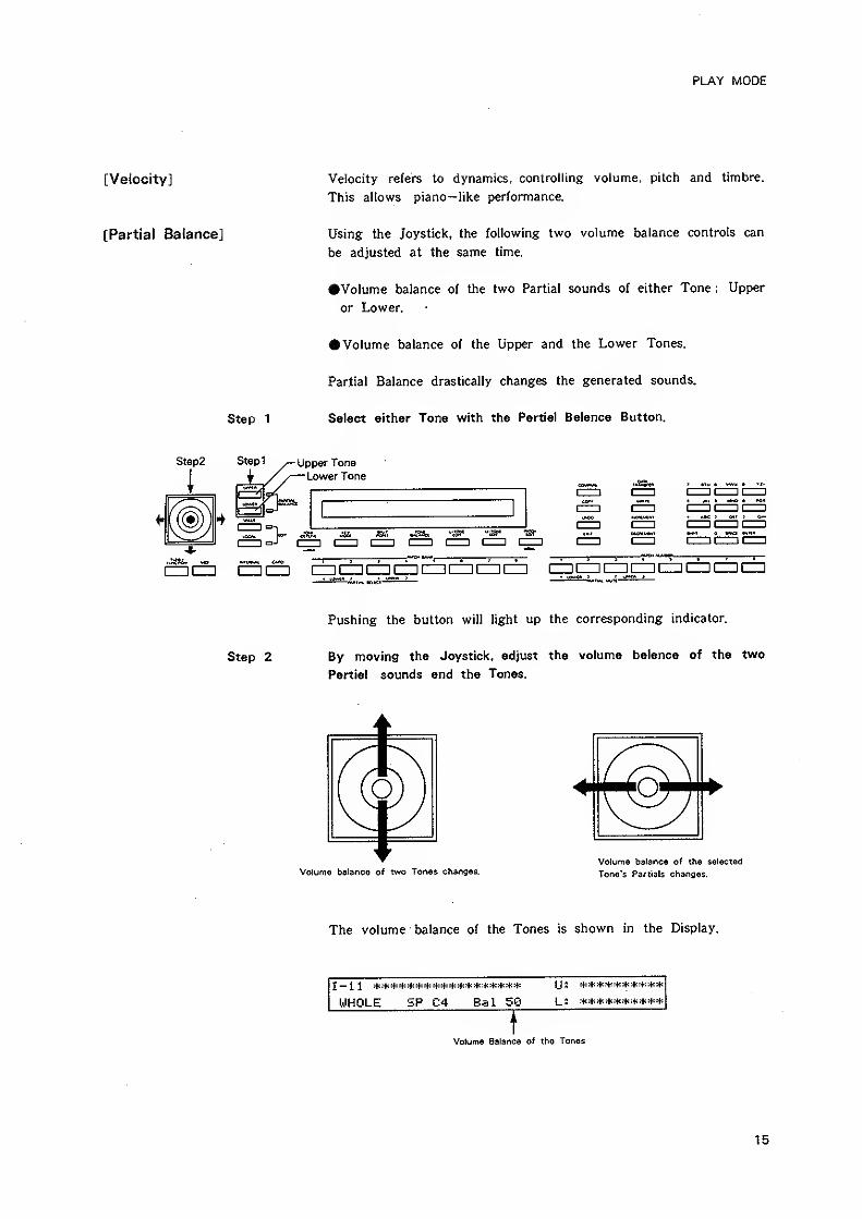
[Velocity]
[Partial Balance]
Step2
i
Step 1
Stepi
i
Velocity refers to dynamics, controlling volume, pitch and timbre.
This allows piano— like performance.
Using the Joystick, the following two volume balance controls can
be adjusted at the same time.
•Volume balance of the two Partial sounds of either Tone : Upper
or Lower.
• Volume balance of the Upper and the Lower Tones.
Partial Balance drastically changes the generated sounds.
Select either Tone with the Partial Balance Button.
Upper Tone
Lower Tone
yI—
I
'—"—
I
IZDCZ! [ZZII=ICZlCZI[ZZ]CZilZDCZD l=3iCD CZi IZDCD
Step 2
Pushing the button will light up the corresponding indicator.
By moving the Joystick, adjust the volume balance of the two
Partial sounds and the Tones.
Volume balance of two Tones changes.Volume balance of the selected
Tone's Partia Is changes.
The volume balance of the Tones is shown in the Display.
I — 11 :ti:{<4:*:t:4:>tirf:4<4::f *4::4<4:4<^4< Ijl **********
WHOLE SP C4 Bal SQ L: **********
Volume Balance of the Tones
15
PLAY MODE
^The volume balance you have set here is not automatically written, into
memory, and therefore vi/ill be erased when another Patch is selected.
*To write the Patch with a new Partial Balance setting, follow the
"Writing Procedure" on page 28.
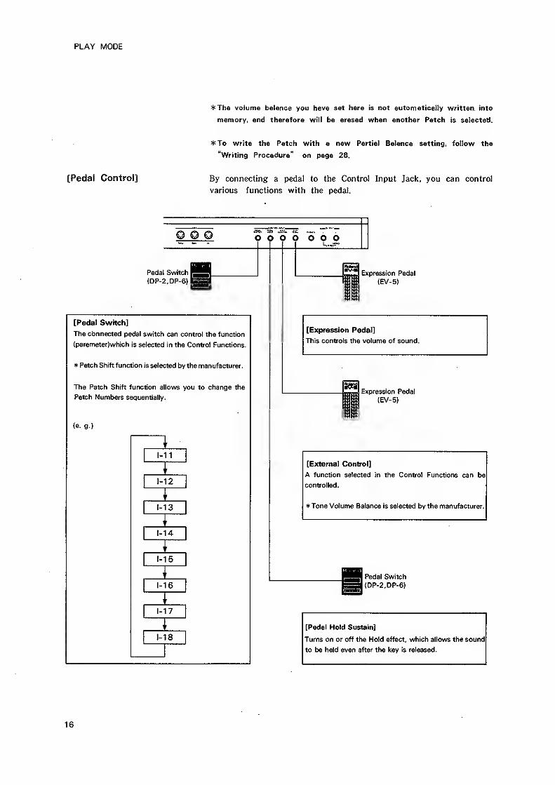
[Pedal Control] By connecting a pedal to the Control Input Jack, you can control
various functions with the pedal.
o o o o o o o o o
Pedal SwitchI
(DP-2,DP-6)
[Pedal Switch]
The cbnnected pedal switch can control the function
(parameter}which is selected in the Control Functions.
* Patch Shift function is selected by the manufacturer.
The Patch Shift function allows you to change the
Patch Numbers sequentially.
{e. g.)
1-11
1-12
1-13
1-14
1-15
1-16
1-17
1-18
Expression Pedal
(EV-5)
[Expression Pedal]
This controls the volume of sound.
Expression Pedal
(EV-5)
[External Confrol]
A function selected in the Control Functions can be
controlled.
Tone Volume Balance is selected by the manufacturer.
Pedal Switch
|{DP-2,DP-6)
[Pedal Hold Sustain]
Turns on or off the Hold effect, which allows the sound
to be held even after the key is released.
16
PLAY MODE
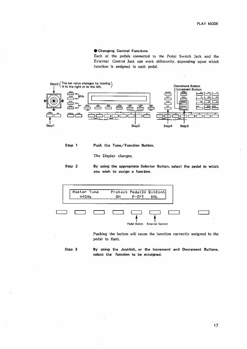
• Changing Control Functions
Each of the pedals connected to the Pedal Switch Jack and the
Externa) Control Jack can work differently, depending upon which
function is assigned to each pedal.
Steps ( "^^^ value changes by moving \
I
\ it to the right or to the left. / Decrement ButtonIncrement Button
«f<£t bI^h tZ^Z
T[=i cziizzi izziiiiDizzicztizzicz] =icz} airpfmri-ii—ii—
i
i—ii—
i
I tOMnJ^^^ ^^j^
^^ryi 7 I ich
Stepi Step2 Step4 Step3
Step 1 Push the Tune/Function Button.
The Display changes.
Step 2 By using the appropriate Selector Button, select the pedal to which
you wish to assign a function.
Master Tune Protect- Pedal SW ExtCont442Hz OH P-SFT ERL
t tPedal Switch External Control
Pushing the button will cause the function currently assigned to the
pedal to flash.
Step 3 By using the Joystick, or the Increment and Decrement Buttons,
select the function to be asssigned.
17
PLAY MODE
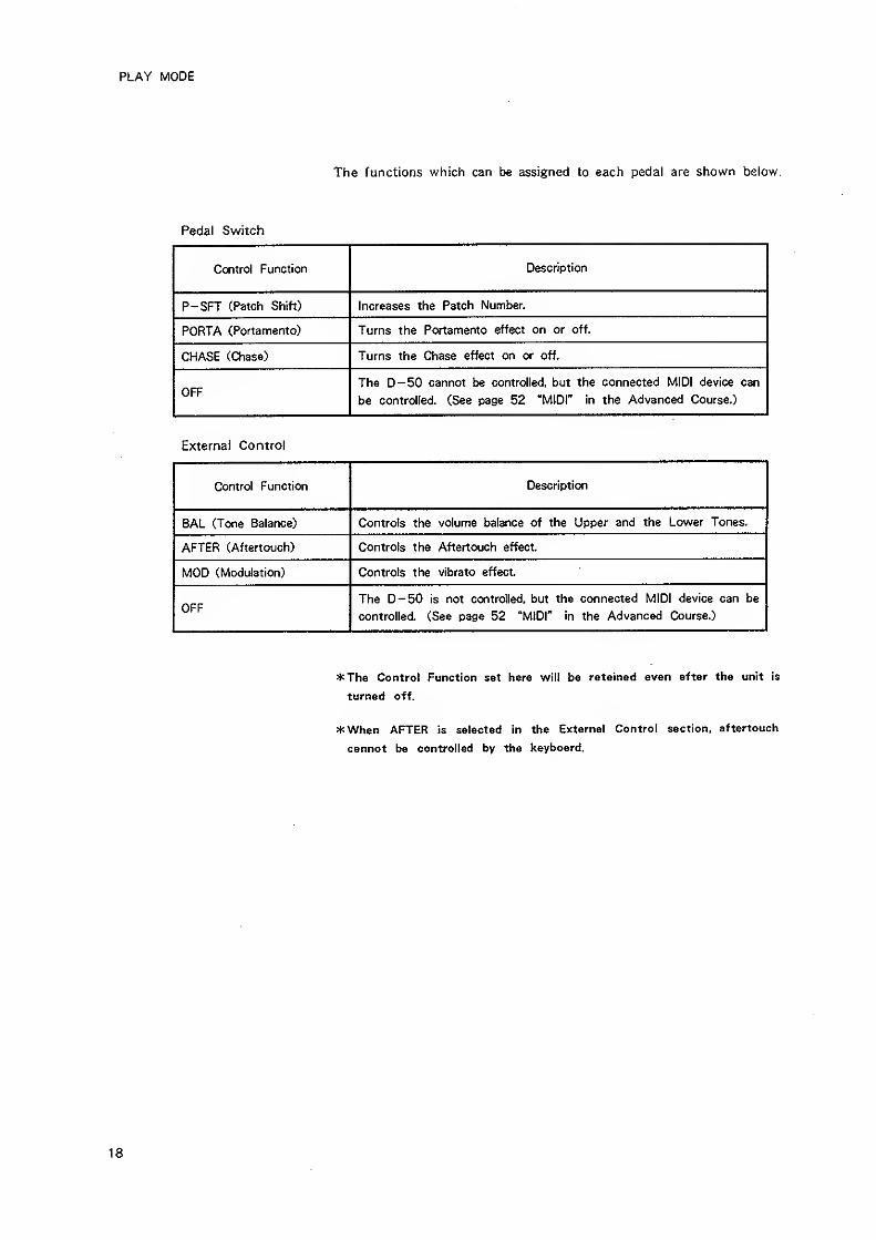
The functions which can be assigned to each pedal are shown below.
Pedal Switch
Control Function Description
P-SFT (Patch Shift) Increases the Patch Number.
PORTA (Portamento) Turns the Portamento effect on or off.
CHASE (Chase) Turns the Chase effect on or off.
OFFThe D-50 cannot be controlled, but the connected MIDI device can
be controlled. (See page 52 "MIDI" in the Advanced Course.)
External Control
Control Function Description
BAL (Tone Balance) Controls the volume balance of the Upper and the Lower Tones.
AFTER (Aftertouch) Controls the Aftertouch effect.
MOD (Modulation) Controls the vibrato effect.
OFFThe D-50 is not controlled, but the connected MIDI device can be
controlled. (See page 52 "MIDI" in the Advanced Course.)
*ThG Control Function set here will be retained even after the unit is
turned off.
*Whon AFTER is selected in the External Control section, aftertouch
cannot be controlled by the keyboard.
18
EDITING PERFORMANCE CONTROLLING FUNCTIONS
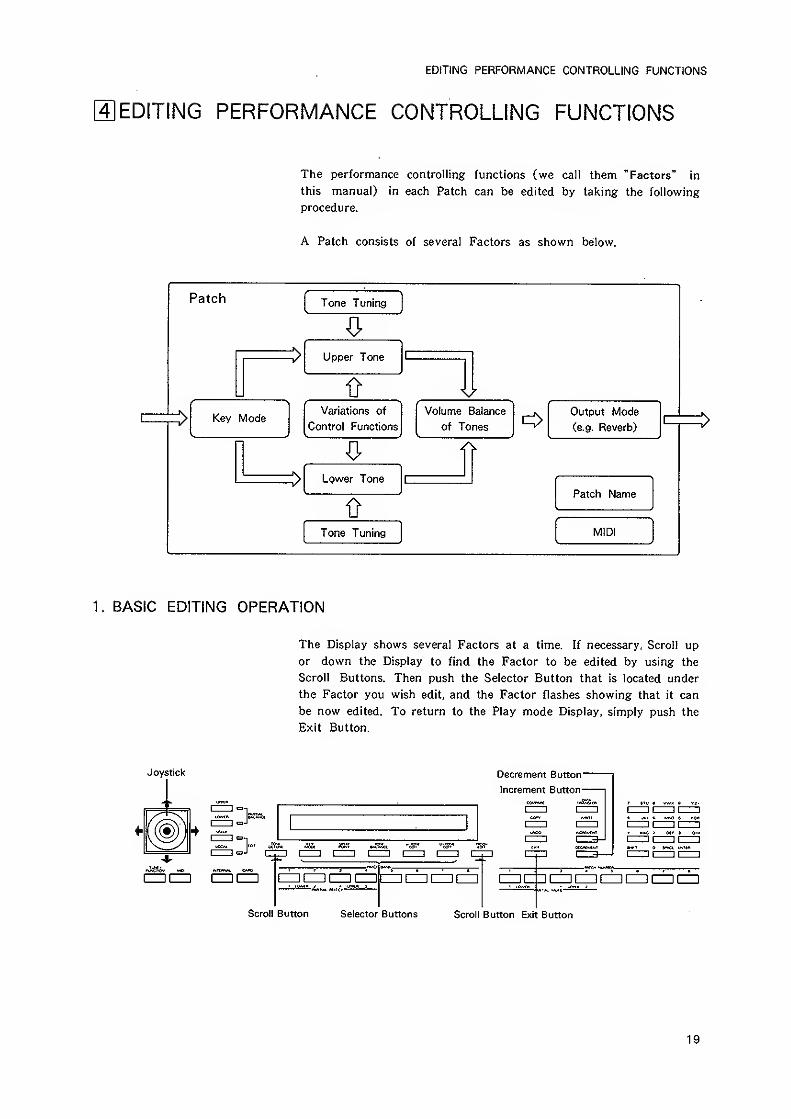
4] EDITING PERFORMANCE CONTROLLING FUNCTIONS
The performance controlling functions (we call them "Factors" in
this manual) in each Patch can be edited by taking the following
procedure.
A Patch consists of several Factors as shown below.
Patch Tone Tuning
Upper Tone
1>
Key ModeVariations of
Control Functions
Volume Balance
of Tones
Output Mode
Ce.g. Reverb)
Lower Tone
Patch Name
Tone Tuning MIDI
1 . BASIC EDITING OPERATION
The Display shows several Factors at a time. If necessary, Scroll up
or down the Display to find the Factor to be edited by using the
Scroll Buttons. Then push the Selector Button that is located under
the Factor you wish edit, and the Factor flashes showing that it can
be now edited. To return to the Play mode Display, simply push the
Exit Button.
Joystick Decrement Button
Increment Button-
Scroll Button Selector Buttons Scroll Button Exit Button
19
EDITING PERFORMANCE CONTROLLING FUNCTIONS
How to change the value of a Factor
•To change the value drastically, use the Joystick. Moving the
Joystick to the right will increase the number.
* Usually, moving the Joystick forward and backward does not affect
the value.
•To change the value slightly, use the Increment and the Decrement
Buttons. Pushing the Increment Button increases the number and
pushing the Decrement Button decreases it.
To return to the Play mode Display, you may need to push the Exit
Button several times.
*The edited data will be erased when a new Patch is selected.
*To retain the edited data in memory, follow the "Writing Procedure"
on page 29.
^The D—50 does not allow you to change Patches unless it is turned
to the Play mode by pushing the Exit Button. This is to reduce the
possibility of accidental erasure of the edited data caused by pushing
a Patch Button by mistake.
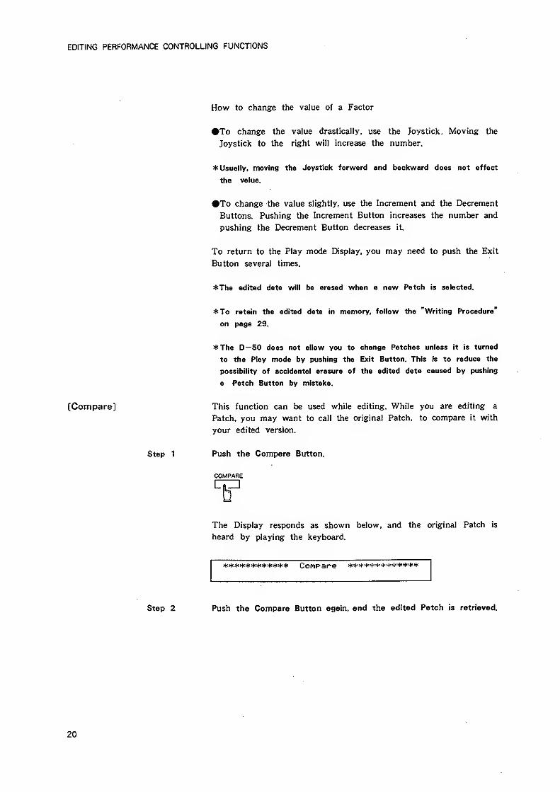
[Compare] This function can be used while editing. While you are editing a
Patch, you may want to call the original Patch, to compare it with
your edited version.
Step 1 Push the Compare Button.
COMPARE
The Display responds as shown below, and the original Patch is
heard by playing the keyboard.
11(4:4:4:4: 4=4=* 44: COPlPare ***4'4:4:4!**4:4:4<*
Step 2 Push the Compare Button again, and the edited Patch is retrieved.
20
EDITING PERFORMANCE CONTROLLING FUNCTIONS
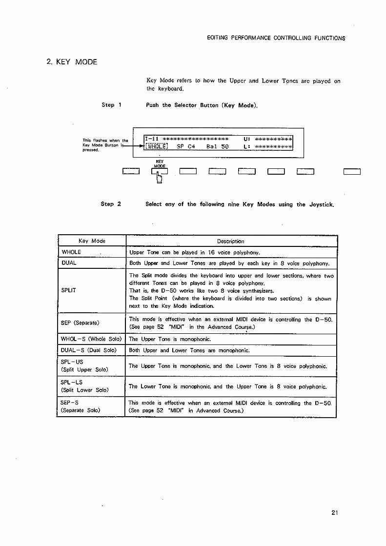
KEY MODE
Key Mode refers to how the Upper and Lower Tones arc played on
Ihc keyboard.
Step 1 Push the Selector Button (Key Mode).
This flashes when tho
Key Mode Button is
—
pressed.[whole] SP C4 Bal 58
KEYMODE
Step 2 Select any of the following nine Key Modes using the Joystick.
Key Mode Description
WHOLE Upper Tone can be played in 16 voice polyphony.
DUAL Both Upper and Lower Tones are played by each key in 8 voice polyphony.
SPLIT
The Split mode divides the keyboard into upper and lower sections, where two
different Tones can be played in 8 voice polyphony.
That is, the D-50 works like two 8 voice synthesizers.
The Split Point (where the keyboard is divided into two sections) is shownnext to the Key Mode indication.
SEP (Separate)This mode is effective when an external MIDI device is controlling the D-50.
(See page 52 "MIDI" in the Advanced Course.)
WHOL-S (Whole Solo) The Upper Tone is monophonic.
DUAL-S (Dual Solo) Both Upper and Lower Tones are monophonic.
SPL-US(Split Upper Solo)
The Upper Tone is monophonic, and the Lower Tone is 8 voice polyphonic.
SPL-LS(Split Lower Solo)
The Lower Tone is monophonic, and the Upper Tone is 8 voice polyphonic.
SEP-S(Separate Solo)
This mode is effective when an external MIDI device is controlling the D-50.
(See page 52 "MIDI" in Advanced Course.)
21
EDITING PERFORMANCE CONTROLLING FUNCTIONS
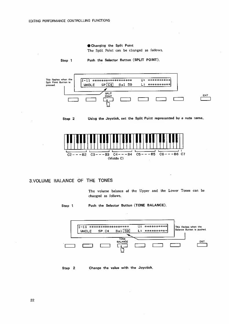
• Changing the Split Point
The Split Point can be changed as follows.
Step 1 Push the Selector Button (SPLIT POINT).
This flashes when the
Sclit Point Button is
pressed.
I — 1 1 ******************
WHOLE SPFcT! Bal 58
Ij: **********
y SPLITPOINT
D
EXIT
Step 2 Using the Joystick, set the Split Point represented by a note name.
!!l!f!l!!ll!ll!!lll!l!fll!!lf>J I
C2 B2 C3 83 C4 84 C5 B5 C6 86 C7(Middle C)
3.V0LUME BALANCE OF THE TONES
Step 1
The volume balance of the Upper and the Lower Tones can be
changed as follows.
Push the Selector Button (TONE BALANCE).
I— 1 1 ******************
WHOLE SP C4 Bal[;5Si]
2 ^f; i|i ifi sfc jjt s(i sfi it"
[_; **********
TONE \.BALANCE
This flaslies when the
Balance Button is pushed.
tip EZID !=EXIT
[HI]
Step 2 Change the value with the Joystick.
22
EDITING PERFORMANCE CONTROLLING FUNCTIONS
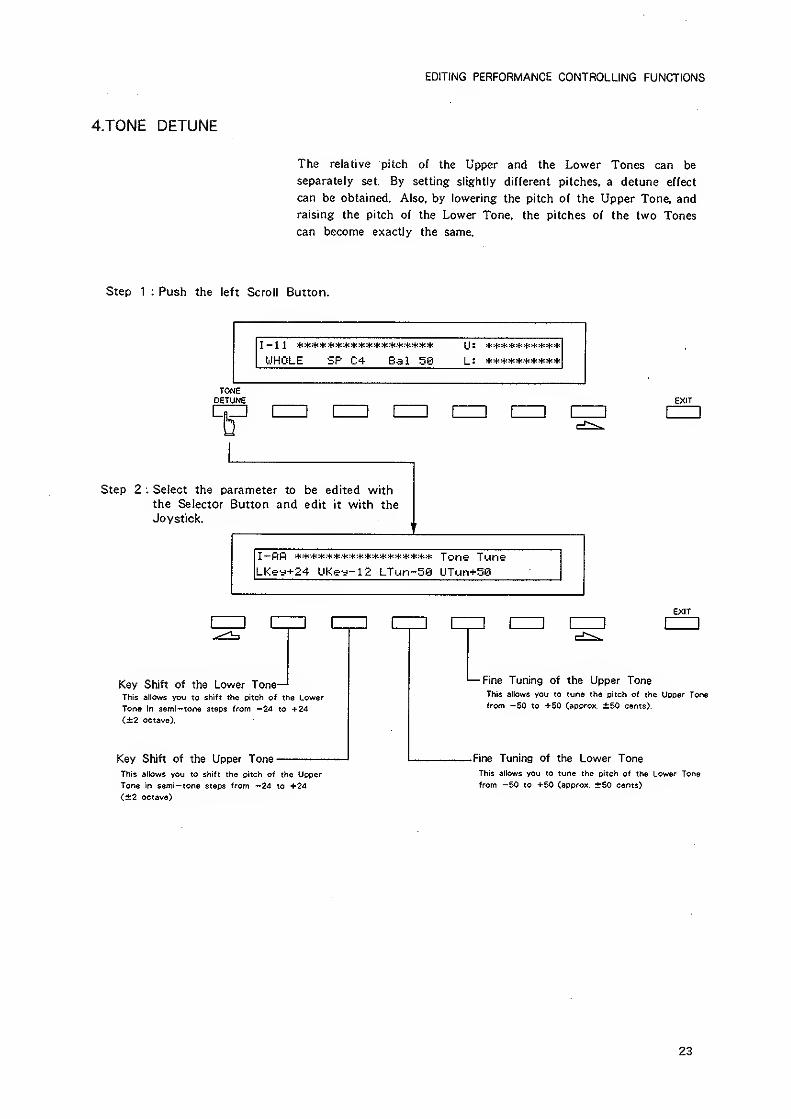
4.T0NE DETUNE
The relative "pitch of the Upper and the Lower Tones can be
separately set. By setting slightly different pitches, a detune effect
can be obtained. Also, by lowering the pitch of the Upper Tone, and
raising the pitch of the Lower Tone, the pitches of the two Tones
can become exactly the same.
Step 1 : Push the left Scroll Button.
WHOLE SP C4 Bal 59
TONEDETUNE EXIT
I I
Step 2 : Select the parameter to be edited with
the Selector Button and edit it with the
Joystick.
LKey+24 LiKey-12 LTun-SS UTun+58
EXIT
Key Shift of the Lower Tone—'This allows you to shift the pitch of the Lower
Tone in semi— tone steps from —24 to +ZA
(±2 octave).
Key Shift of the Upper Tone
'— Fine Tuning of the Upper ToneThis allows you to tune the piioh of the Upper Tone
from -50 to +50 (approx. ±50 cents).
-Fine Tuning of the Lower Tone
This allows you to shift the pitch of the Upper
Tone in semi— tone steps from —24 to +24
<±2 octave)
This allows you to tune the pitch of the Lower Tone
from -50 to +50 (approx. ±50 cents)
23
EDITING PERFORMANCE CONTROLLING FUNCTIONS
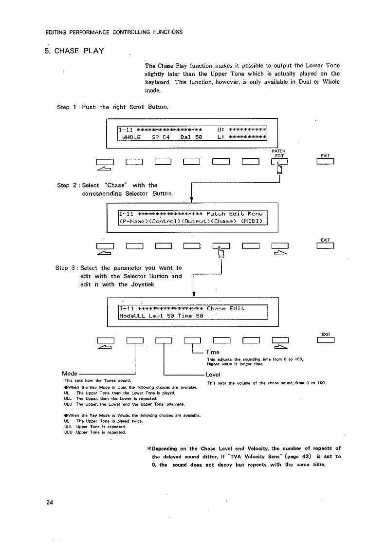
5. CHASE PLAY
The Chase Play function makes it possible to output the Lower Tone
slightly later than the Upper Tone which is actually played on the
keyboard. This function, however, is only available in Dual or Whole
mode.
Step 1 : Push the right Scroll Button.
J ^ sji sf? ^§^ s4i ifj ^t- ifr sf^ 5^5 ^4^s^I^^^t^^^^^§^H^tt'^^
WHOLE SP C4 Bal 50 L: **********
PATCHEDIT EXIT
1=1 nzj [zzi != nm czzi nzD nz
Step 2 : Select "Chase" with the
corresponding Selector Button.
I -1 1 ****************** Pat^ch Edit MenuCP-Name^ ^Control > (Output ><Chase> <MIDI
>
COEXIT
Step 3 : Select the parameter you want to
edit with the Selector Button and
edit it with the Joystick
I — 1 1 5^{^^{l^!*!^^*!^;*^f;**l^:!^(*^^;*** Clras-e EditModeULL Levi 5S Tine 58
EXIT
ModeThis sets how the Tones sound.
#When the Key Mode is Dual, the following choices are available.
UL The Upper Tone then the Lower Tone is played.
ULL The Upper, then the Lower is repeated.
ULU The Upper, the Lower and the Upper Tone alternate.
When the Key Mode is W>o!e, the following choices are available.
UL The Upper Tone is played twice.
ULL Upper Tone is repeated.
ULU Upper Tone is repeated.
TimeThis adjusts the sounding time from to 100.
Higher value is longer time.
Level
This sets the volume of the chase sound, from to 100.
* Depending on the Chase Level and Velocity, the number of repeats of
the delayed sound differ. If "TVA Velocity Sens" (page 43) is set to
0, the sound does not decay biit repeats with the same time.
24
EDITING PERFORMANCE CONTROLLING FUNCTIONS
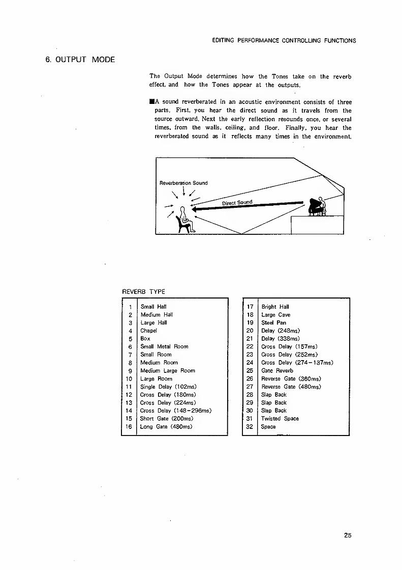
6. OUTPUT MODE
The Output Mode determines how the Tones take on the reverb
effect, and how the Tones appear at the outputs.
A sound reverberated in an acoustic environment consists of three
parts. First, you hear the direct sound as it travels from the
source outward. Next the early reflection resounds once, or several
times, from the walls, ceiling, and floor. Finally, you hear the
reverberated sound as it reflects many times in the environment.
REVERB TYPE
1 Small Hall 17 Bright Hall
2 Medium Hall 18 Large Cave
3 Large Hall 19 Steel Pan
4 Chapel 20 Delay (248ms)
5 Box 21 Delay (338ms)
6 Small Metal Room 22 Cross Delay (157ms)
7 Smalt Room 23 Cross Delay (252ms)
8 Medium Room 24 Cross Delay (274- 137ms)
9 Medium Large Room 25 Gate Reverb
10 Large Room 26 Reverse Gate (360ms)
11 Single Delay C102ms> 27 Reverse Gate (480ms)
12 Cross Delay (180ms) 28 Slap Back
13 Cross Delay (224ms) 29 Slap Back
14 Cross Delay (148-296ms) 30 Slap Back
15 Short Gate (200ms) 31 Twisted Space
16 Long Gate (480ms) 32 Space
25
EDITING PERFORMANCE CONTROLLING FUNCTIONS
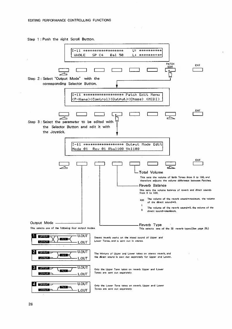
Step 1 : Push the right Scroll Button.
UHOLE SP C4 Bal 56
U ^ ^
PATCHEDIT
EXIT
Step 2 : Select "Output Mode" with the
corresponding Selector Button.
I — 11 Pat^ch Edi't Menu<P-Nane><ControI><OutPut><:Chase> G-IIDn
nz3 C
EXIT
Step 3 : Select the parameter to be edited with
the Selector Button and edit it with
the Joystick.
I -1 1 :i.*^t:^^^***^^^***>^^****** OutPUt- Mode Edi t
Mode 01 Rev 91 RballSe UollSe
EXIT
Output Mode
This selects one of the followng four output modes.
Total VolumeThis sets the volume of both Tones from to 100, and
therefore adjusts the volume difference between Patches,
Reverb Balance
This sets the volume balance of reverb and direct sounds
from to too.
100
I
The volume of the reverb soundmaximum, the volume
of the direct sound«»0.
The volume of the reverb sound**0. the volume of the
direct soundo maximum.
Reverb TypeThis selects one of the 32 reverb types.(See page 25.)
Stereo reverb works on the mixed sound of Upper and
Lower Tones, and is sent out in stereo.
U.OUT
LOUTThe Mixture of Upper and Lower takes on stereo reverb, and
the direct sound is sent out separately for Upper and Lower.
IMtigM—
y
U.OUT
LOUTOnly the Upper Tone takes on reverb. Upper and Lower
Tones are sent out separately.
U.OUT
LOUT
Only the Lower Tone takes on reverb. Upper and Lower
Tones are sent out separately.
26
EDITING PERFORMANCE CONTROLLING FUNCTIONS
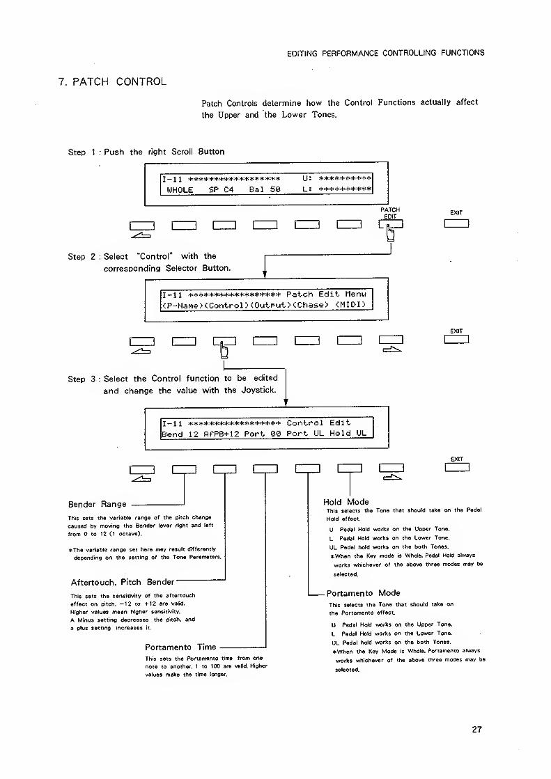
7. PATCH CONTROL
Patch Controls determine how the Control Functions actually affect
the Upper and the Lower Tones.
Step 1 : Push the right Scroll Button
WHOLE SP C4 Bal 58
(J: **********
L I **********
PATCHEDIT
EXIT
] HID [ 3 UZn
Step 2 : Select "Control" with the
corresponding Selector Button.
I~ 1 1 ****************** Patch Edit Menu
;P-Hane> (Control > <0utput > CChase^ <MIDI >
EXIT
CZZ]
Step 3 : Select the Control function to be edited
and change the value with the Joystick.
I- 1 1 ****************** Control Edi
t
Bend 12 nfPB+12 Port BS Port UL Hold UL
] C
Bender Range
iZZ] [
This sets the variable range of the pitch change
caused by moving the Bender lever right and left
from to 12 (1 octave).
The variable range set here may result differently
depending on the setting of the Tone Parameters,
Aftertouch. Pitch Bender
This sets the sensitivity of the aftertouch
effect on pitch. —12 to +12 are valid.
Higher values mean higher sensitivity.
A Minus setting decreases the oitch, and
a plus setting increases it.
Portamento Time
This sets the Portamento time from one
note to another. 1 to 100 are valid. Higher
values make the time longer.
EXIT
] [
Hold ModeThis selects the Tone that should take on the Pedal
Hold effect.
U Pedal Hold works on the Upper Tone.
L Pedal Hold works on the Lower Tone.
UL Pedal hold works on the both Tones.
When the Key mode is Whole. Pedal Hold always
works whichever of the above three modes may be
selected.
- Portamento ModeThis selects the Tone that should take on
the Portamento effect,
U Pedal Hold works on the Upper Tone.
L Pedal Hold works on the Lower Tone.
UL Pedal hold works on the both Tones.
When the Key Mode is Whole, Portamento always
works whichever of the above three modes may be
selected.
27
WRITING
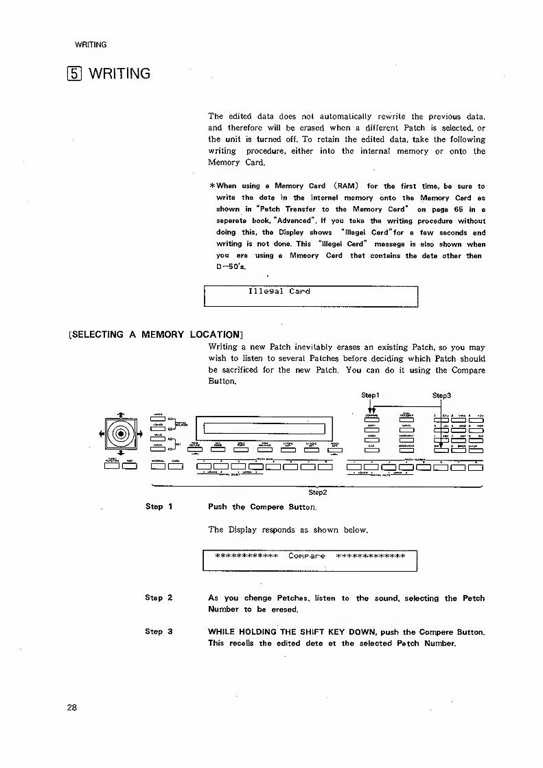
\E WRITING
The edited data does not automatically rewrite the previous data,
and therefore will be erased when a different Patch is selected, or
the unit is turned off. To retain the edited data, take the following
writing procedure, either into the internal memory or onto the
Memory Card.
4: When using a Memory Card (RAM) for the first time, be sure to
write the data in the internal memory onto the Memory Card as
shown in "Patch Transfer to the Memory Card" on page 65 in a
separate book, "Advanced". If you take the writing procedure without
doing this, the Display shows "Illegal Card"for a few seconds and
writing is not done. This "illegal Card" message is also shown when
you are using a Mmeory Card that contains the data other than
D-50's.
Illegal Card
[SELECTING A MEMORY LOCATION]Writing a new Patch inevitably erases an existing Patch, so you maywish to listen to several Patches before deciding which Patch should
be sacrificed for the new Patch. You can do it using the Compare
Button.
Stepi
ir
Steps
5^
CZDCZI dZICZ) CZ] CZI [ZZI CD [ZZI en CZI mi—II—II—
I
Step 1
Step2
Push the Compare Button.
The Display responds as shown below.
Step 2 As you change Patches, listen to the sound, selecting the Patch
Number to be erased.
Step 3 WHILE HOLDING THE SHIFT KEY DOWN, push the Compare Button.
This recalls the edited data at the selected Patch Number.
28
WRITING
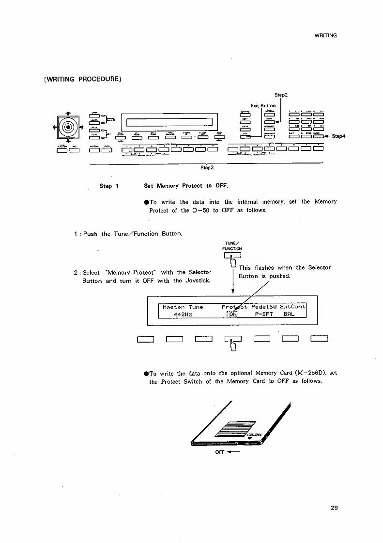
[WRITING PROCEDURE]
Step2
Exit Button
>JUS. m
-Step4
3c±] as 5SSiSEdc±i[±][±i [±]c±:c±)i=tc±]c=]iz=i* lOMJt J .. i fnm J ' ' ..rti
'
Steps
Step 1 Set Memory Protect to OFF.
To write the data into the internal memory, set the Memory
Protect of the D-50 to OFF as follows.
1 : Push the Tune/Function Button.
2 : Select "Memory Protect" with the Selector
Button and turn it OFF with the Joystick.
TUNE/FUNCTION
This flashes when the Selector
Button is pushed.
Master Tune Pro^^t PedalSW ExtCont
442HS [on] P-5FT BflL
iZIIi C
To write the data onto the optional Memory Card CM-256D), set
the Protect Switch of the Memory Card to OFF as follows.
OFF
29
WRITING
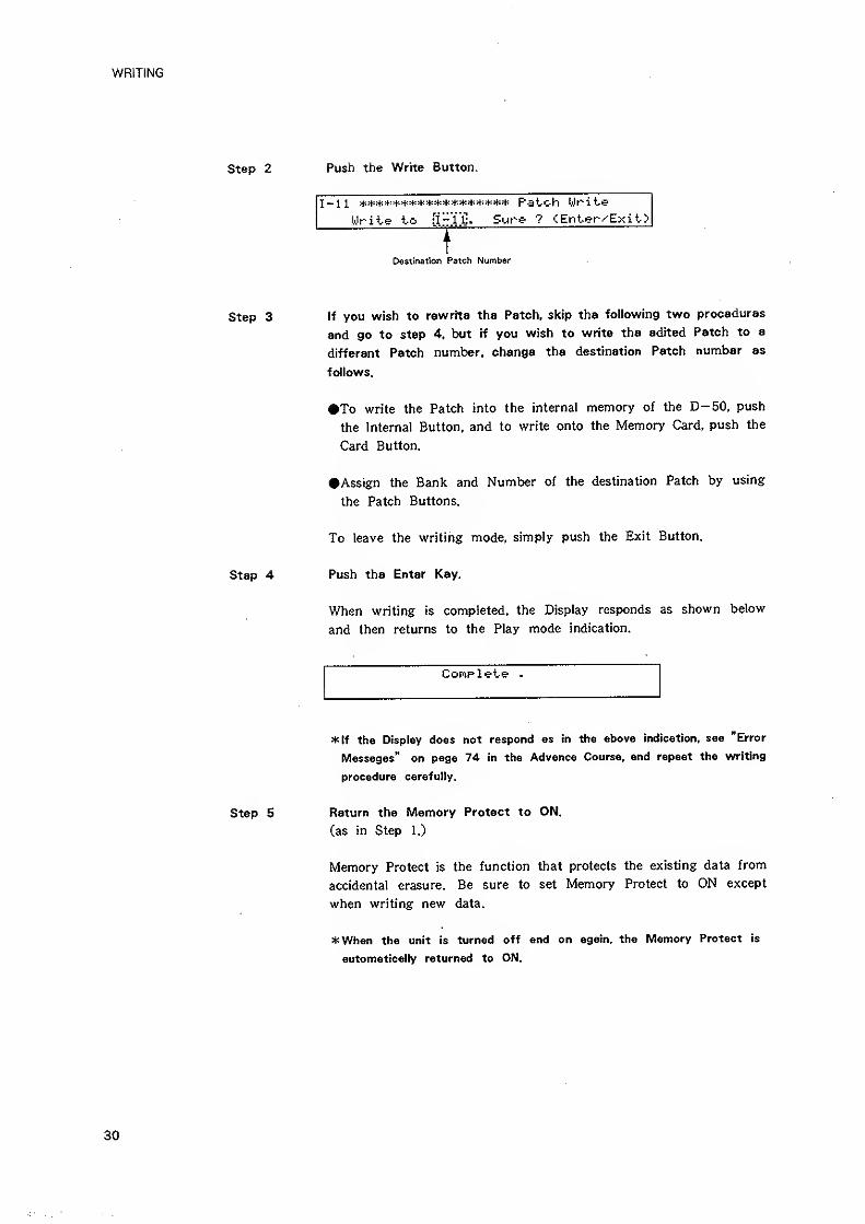
Step 2 Push the Write Button.
l-ll **^t:^+:^^^******+***^^^** Patch Write
Write to fi-ll"!. Sure ? <Enter^Exit>........
Destination Patch Number
Step 3 If you wish to rewrite the Patch, skip the following two procedures
and go to step 4, but if you wish to write the edited Patch to a
different Patch number, change the destination Patch number as
follows.
To write the Patch into the interna! memory of the D-50, push
the Internal Button, and to write onto the Memory Card, push the
Card Button.
•Assign the Bank and Number of the destination Patch by using
the Patch Buttons.
To leave the writing mode, simply push the Exit Button.
Step 4 Push the Enter Key.
When writing is completed, the Display responds as shown below
and then returns to the Play mode indication.
CoFiplete .
*tf the Display does not respond as in the above indication, see "Error
Messages" on page 74 in the Advance Course, and repeat the writing
procedure carefully.
Step 5 Return the Memory Protect to ON.
(as in Step 1.)
Memory Protect is the function that protects the existing data from
accidental erasure. Be sure to set Memory Protect to ON except
when writing new data.
*When the unit is turned off and on again, the Memory Protect is
automatically returned to ON.
30
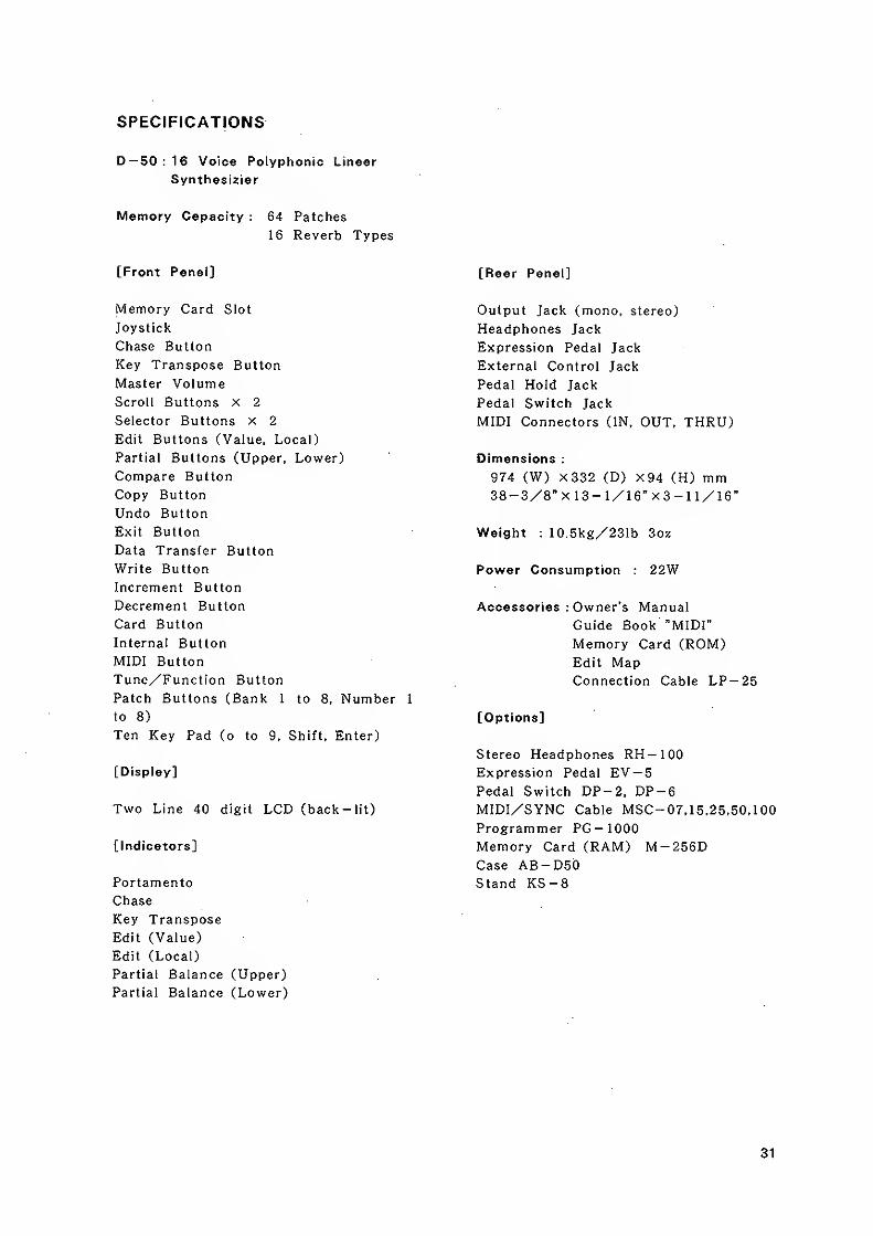
SPECIFICATIONS
D-50:16 Voice Polyphonic Linear
Synthesizier
Memory Capacity : 64 Patches
1 6 Reverb Types
[Front Panel]
Memory Card Slot
Joystick
Chase Button
Key Transpose Button
Master VolumeScroll Buttons x 2
Selector Buttons x 2
Edit Buttons (Value, Local)
Partial Buttons (Upper, Lower)
Compare Button
Copy Button
Undo Button
Exit Button
Data Transfer Button
Write Button
Increment Button
Decrement Button
Card Button
Internal Button
MIDI Button
Tune/Function Button
Patch Buttons (Bank 1 to 8. Number 1
to 8)
Ten Key Pad (o to 9, Shift, Enter)
[Display]
Two Line 40 digit LCD (back-lit)
[Indicators]
Portamento
Chase
Key Transpose
Edit (Value)
Edit (Local)
Partial Balance (Upper)
Partial Balance (Lower)
[Rear Panel]
Output Jack (mono, stereo)
Headphones Jack
Expression Pedal Jack
External Control Jack
Pedal Hold Jack
Pedal Switch Jack
MIDI Connectors (IN, OUT. THRU)
Dimensions :
974 (W) X332 (D) x94 (H) mm38-3/8" X 13- 1/16" X 3- U/16"
Weight : 10.5kg/231b 3oz
Power Consumption 22W
Accessories : Owner's Manual
Guide Book "MIDI"
Memory Card (ROM)Edit MapConnection Cable LP — 25
[Options]
Stereo Headphones RH-100Expression Pedal EV —
5
Pedal Switch DP-2, DP~6MIDI/SYNC Cable MSC- 07. 15.25.50,100
Programmer PC- 1000
Memory Card (RAM) M-256DCase AB-D5bStand KS-8
31

MIDI
i
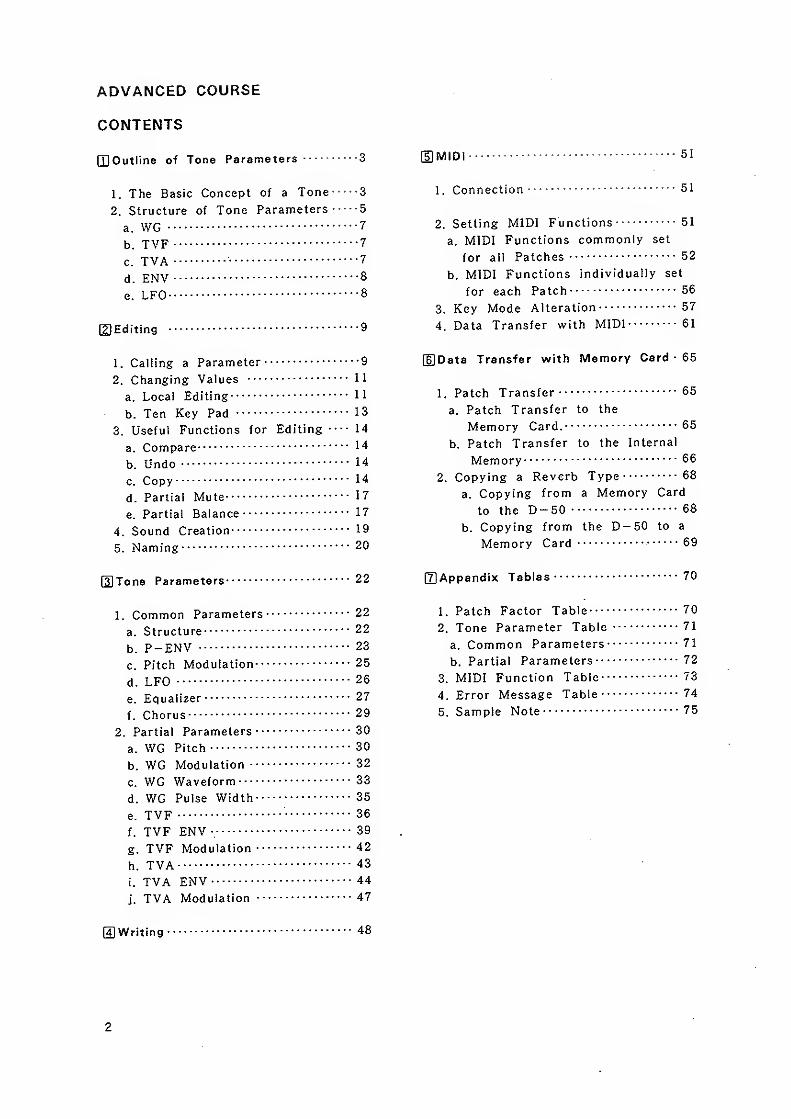
ADVANCED COURSE
CONTENTS
[QOutline of Tone Parameters 3
1. The Basic Concept of a Tone 3
2. Structure of Tone Parameters 5
a. WG 7
b. TVF 7
c. TVA 7
d. ENV 8
e. LFO 8
©Editing 9
1. Calling a Parameter 9
2. Changing Values 1
1
a. Local Editing 11
b. Ten Key Pad 13
3. Useful Functions for Editing — 14
a. Compare 14
b. Undo 14
c. Copy 14
d. Partial Mute 17
e. Partial Balance 17
4. Sound Creation 19
5. Naming 20
OTone Parameters 22
1. Common Parameters 22
a. Structure 22
b. P-ENV 23
c. Pitch Modulation 25
d. LFO 26
e. Equalizer 27
f. Chorus 29
2. Partial Parameters 30
a. WG Pitch 30
b. WG Modulation 32
c. WG Waveform 33
d. WG Pulse Width 35
e. TVF 36
f. TVF ENV , 39
g. TVF Modulation 42
h. TVA 43
i. TVA ENV 44
j. TVA Modulation 47
OWriting 48
[5)MIDI 51
1. Connection 51
2. Setting MIDI Functions 51
a. MIDI Functions commonly set
for all Patches 52
b. MIDI Functions individually set
for each Patch 56
3. Key Mode Alteration 57
4. Data Transfer with MIDI 61
(DData Transfer w^ith Memory Card • 65
1. Patch Transfer 65
a. Patch Transfer to the
Memory Card. 65
b. Patch Transfer to the Internal
Memory 66
2. Copying a Reverb Type 68
a. Copying from a Memory Card
to the D-50 68
b. Copying from the D— 50 to a
Memory Card 69
[TjAppendix Tables 70
1. Patch Factor Table 70
2. Tone Parameter Table 71
a. Common Parameters 71
b. Partial Parameters 72
3. MIDI Function Table 73
4. Error Message Table 74
5. Sample Note 75
2
OUTLINE OF TONE PARAMETERS
Q] OUTLINE OF TONE PARAMETERS
1 . THE BASIC CONCEPT OF A TONE
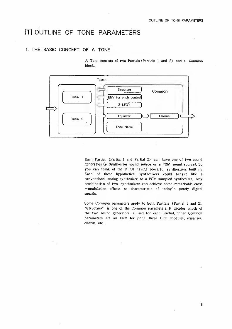
A Tone consists of two Partials (Partials 1 and 2) and a Commonblock.
Tone
/
Partial 1
t
/ >
Partial 2
Structure Common
[eNV for pitch control]
[ 3 LFO's]
> [ EqualizerJCZ[> [ Chorus ] C
Tone Name
Each Partial (Partial 1 and Partial 2) can have one of two sound
generators (a Synthesizer sound source or a PCM sound source). So
you can think of the D-50 having powerful synthesizers built in.
Each of these hypothetical synthesizers could behave like a
conventional analog synthesizer, or a PCM sampled synthesizer. Anycombination of two synthesizers can achieve some remarkable cross
— modulation effects , so characteristic of today ' s purely digital
sounds.
Some Common parameters apply to both Partials (Partial 1 and 2).
"Structure" is one of the Common parameters. It decides which of
the two sound generators is used for each Partial. Other Commonparameters are an ENV for pitch, three LFO modules, equalizer,
chorus, etc.
3
OUTLINE OF TONE PARAMETERS
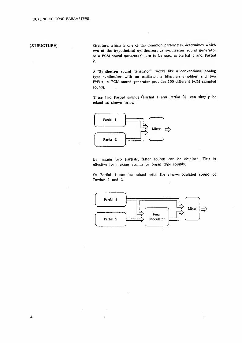
[STRUCTURE] Slruclure. which is one of the Common parameters, determines which
two of the hypothetical synthesizers (a synthesizer sound generator
or a PCM sound generator) are to be used as Partial 1 and Partial
2.
A "Synthesizer sound generator" works like a conventional analog
type synthesizer with an oscillator, a filter, an amplifier and two
ENV's. A PCM sound generator provides 100 different PCM sampled
sounds.
These two Partial sounds (Partial 1 and Partial 2) can simply be
mixed as shown below.
Partial 1
\ )
/
Partial 2
)
By mixing two Partials, fatter sounds can be obtained. This is
effective for making strings or organ type sounds.
Or Partial 1 can be mixed with the ring-modulated sound of
Partials 1 and 2.
f >
Partial 1
\
f
Partial 2
)
Ring
Modulator
4
OUTLINE OF TONE PARAMETERS
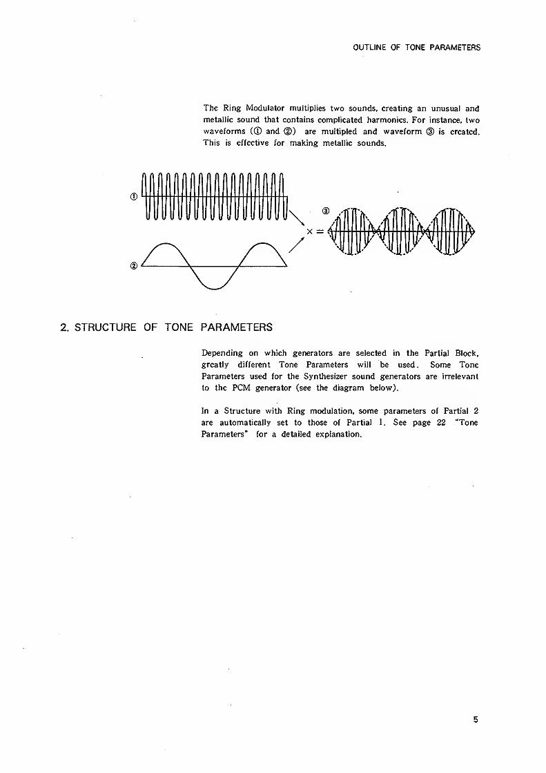
The Ring Modulator multiplies two sounds, creating an unusual and
metallic sound that contains complicated harmonics. For instance, two
waveforms C® and @) are muUipled and waveform @ is created.
This is effective for making metallic sounds.
2. STRUCTURE OF TONE PARAMETERS
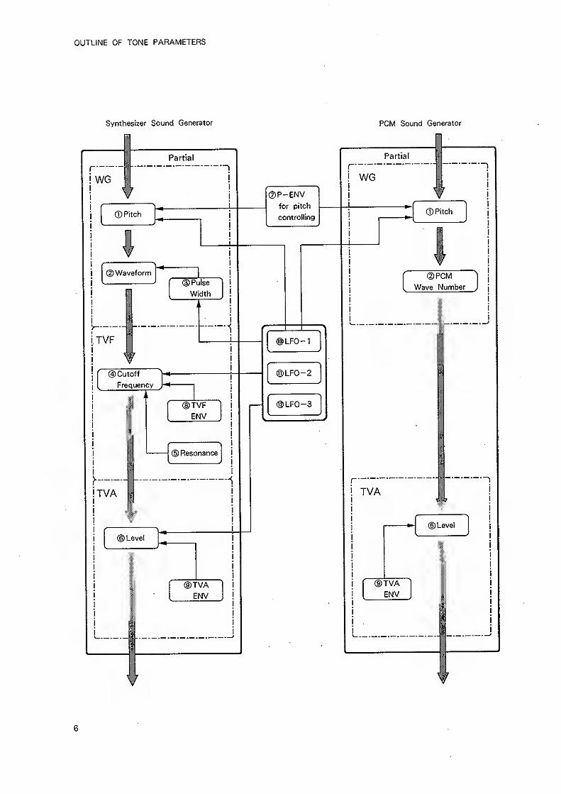
Depending on which generators are selected in the Partial Block,
greatly different Tone Parameters will be used. Some Tone
Parameters used for the Synthesizer sound generators are irrelevant
to the PCM generator (see the diagram below).
In a Structure with Ring modulation, some parameters of Partial 2
are automatically set to those of Partial 1. See page 22 "Tone
Parameters" for a detailed explanation.
5
OUTLINE OF TONE PARAMETERS
Synthesizer Sound Generator PCM Sound Generator
®P-ENVfor pitch
controlling
)LF0-1
®LF0-2
)LF0-3
r"
TVA
(DPCM
Wave Number
©Level
(DTVAENV
6
OUTLINE OF TONE PARAMETERS
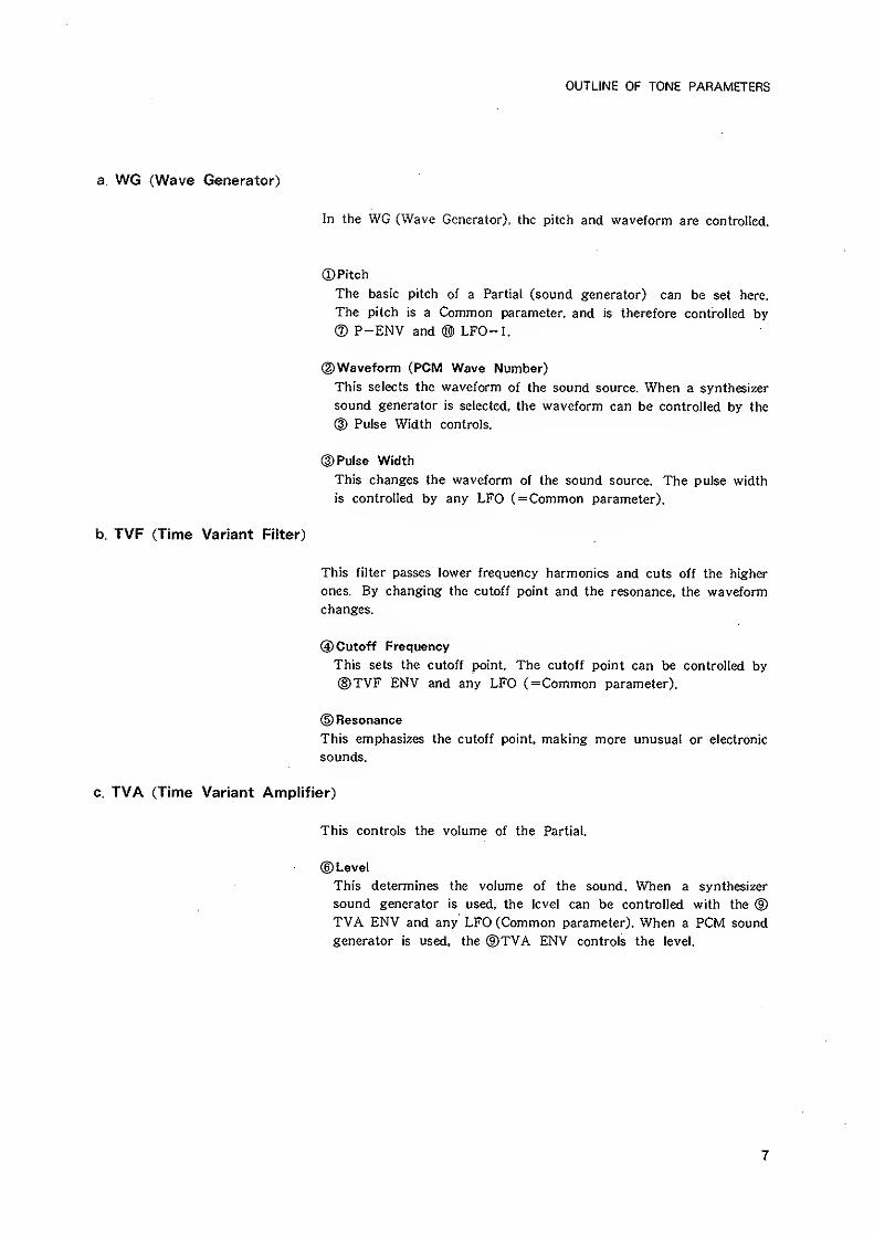
a. WG (Wave Generator)
In the WG (Wave Generator), the pitch and waveform are controlled.
CD Pitch
The basic pitch of a Partial (sound generator) can be set here.
The pitch is a Common parameter, and is therefore controlled by
(2) P-ENV and ® LFO-1.
(|)Waveform (PCM Wave Number)
This selects the waveform of the sound source. When a synthesizer
sound generator is selected, the waveform can be controlled by the
® Pulse Width controls.
©Pulse Width
This changes the waveform of the sound source. The pulse width
is controlled by any LFO (=Common parameter).
b. TVF (Time Variant Filter)
This filter passes lower frequency harmonics and cuts off the higher
ones. By changing the cutoff point and the resonance, the waveform
changes.
©Cutoff Frequency
This sets the cutoff point. The cutoff point can be controlled by
®TVF ENV and any LFO (=Common parameter).
d) Resonance
This emphasizes the cutoff point, making more unusual or electronic
sounds.
c. TVA (Time Variant Amplifier)
This controls the volume of the Partial,
eg) Level
This determines the volume of the sound. When a synthesizer
sound generator is used, the level can be controlled with the (D
TVA ENV and any' LFO (Common parameter). When a PCM sound
generator is used, the @TVA ENV controls the level.
7
OUTLINE OF TONE PARAMETERS
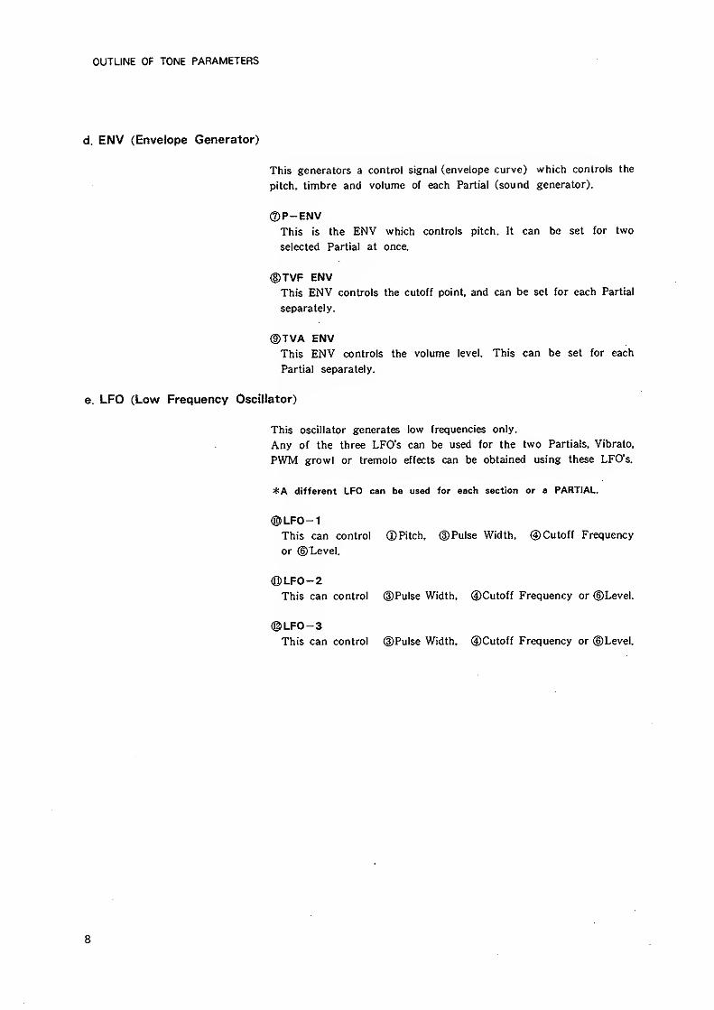
d. ENV (Envelope Generator)
This generators a control signal (envelope curve) which controls the
pitch, timbre and volume of each Partial (sound generator).
®P-ENVThis is the ENV which controls pitch. It can be set for two
selected Partial at once.
®TVF ENVThis ENV controls the cutoff point, and can be set for each Partial
separately.
®TVA ENVThis ENV controls the volume level. This can be set for each
Partial separately.
e. LFO (Low Frequency Oscillator)
This oscillator generates low frequencies only.
Any of the three LFO's can be used for the two Partials, Vibrato,
PWM growl or tremolo effects can be obtained using these LFO's.
*A different LFO can be used for each section or a PARTIAL.
®LF0-1This can control ©Pitch, (DPulse Width, ©Cutoff Frequency
or ©Level.
®LF0-2This can control ©Pulse Width, tDCutoff Frequency or ©Level.
®LF0-3This can control ©Pulse Width, (DCutoff Frequency or ©Level.
8
EDITING
21 EDITING
The D-50 features various parameters which can be edited, therebysynthesizing new sounds. However, it does not feature knobs or
switches on its front panel. Instead, there are two methods of
editing:one is achieved by calling each parameter with the relevant
buttons, and changing the value with the Joystick, or Increment andDecrement Buttons, the other is by using the optional programmerPG-1000, which has al! the necessary panel controls.
For quicker and easier editing or synthesizing from scratch, the PG-1000 may be essential.
*Th8 editing procedure does not automatically rewrite the existing
program, the appropriate writing procedure, on page 18 must be taken.
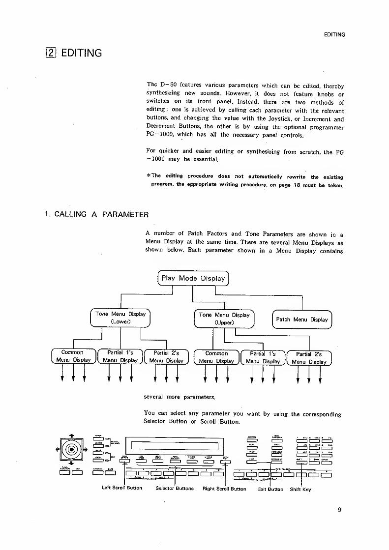
1. CALLING A PARAMETER
A number of Patch Factors and Tone Parameters are shown in a
Menu Display at the same time. There are several Menu Displays as
shown below. Each parameter shown in a Menu Display contains
Play Mode Display
Tone Menu Display
(Lower)
Common
Menu Display
Partial 1's
Menu Display
Partial 2's
^ Menu Display
Tone Menu Display
(Upper)Patch Menu Display
CommonMenu Display
.
Partial I's
Menu Display
Partial 2"s
Menu Display
several more parameters.
You can select any parameter you want by using the corresponding
Selector Button or Scroll Button.
CD CZ] enLeft Scroll Button Selector Buttons Right Scroll Button Exit Button Shift Key
9
EDITING
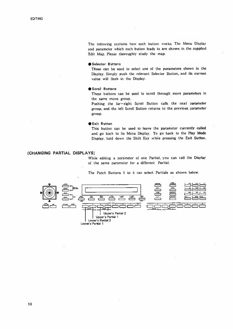
The following explains how each button works. The Menu Display
and parameter which each button leads to are shown in the supplied
Edit Map. Please thoroughly study the map.
• Selector Buttons
These can be used to select one of the parameters shown in the
Display. Simply push the relevant Selector Button, and its current
value will flash in the Display.
• Scroll Buttons
These buttons can be used to scroll through more parameters in
the same menu group.
Pushing the far- right Scroll Button calls the next parameter
group, and the left Scroll Button returns to the previous parameter
group.
• Exit Button
This button can be used to leave the parameter currently called
and go back to its Menu Display. To go back to the Play Mode
Display, hold down the Shift Key while pressing the Exit Button.
[CHANGING PARTIAL DISPLAYS]While editing a parameter of one Partial, you can call the Display
of the same parameter for a different Partial.
The Patch Buttons 1 to 4 can select Partials as shown below.
I—
I
I 1 I 1
dDIZZ! CZICZI IZPfZpiZZIIZZIIZDCZICZICZ] CD 1=1 CZ]CD CZI CZ) (ZD C=l
upper's Partial 2Upper's Partial 1
Lower's Partial 2Lower's Partial 1
10
EDITING
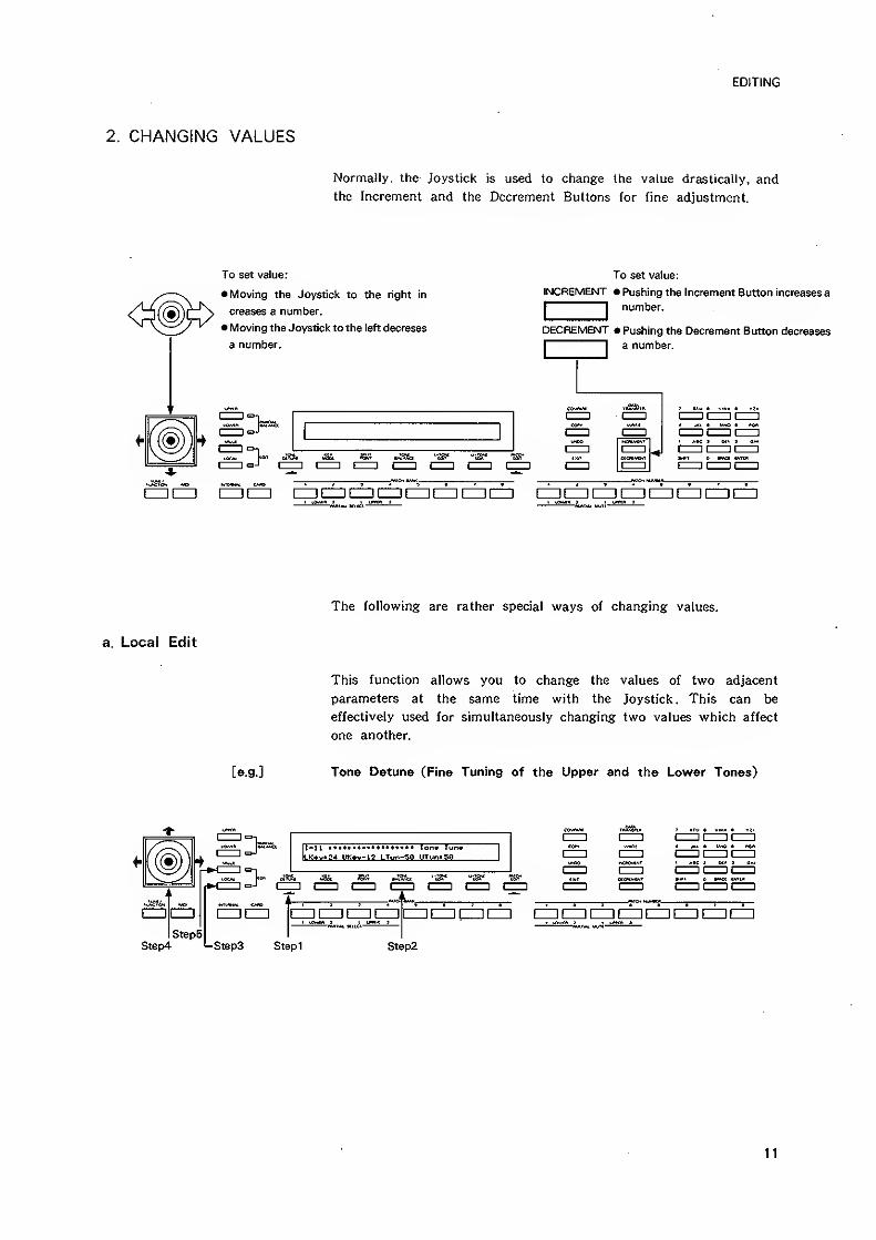
CHANGING VALUES
Normally, the Joystick is used to change Ihe value drastically, and
the Increment and the Decrement Buttons for fine adjustment.
To set value:
• Moving the Joystick to the right in
creases a number.
• Moving the Joystick to the left decreses
a number.
To set value:
INCREMENT • Pushing the Increment Button increases a
I I number.
DECREMENT • Pushing the Decrement Button decreases
I I a number.
I 1
I 1
r^
(ZZiiZZI CIDIZZl iZZICZKZZICniZZIIZZIIZZICZ] [ZZDCZIIZZlCZZICZDIZZlCnCZD
The following are rather special ways of changing values.
Local Edit
This function allows you to change the values of two adjacent
parameters at the same time with the Joystick. This can be
effectively used for simultaneously changing two values which affect
one another.
[e.9.] Tone Detune (Fine Tuning of the Upper and the Lower Tones)
11-11 Ion» T
IlK*v.S4 w:«v-12 LT»r.-50
IZZ] IZZl [ZZI cz] cz] czzi (ZZIIZZI [ZZIIZZIen czicncz]
Step2
11
EDITING
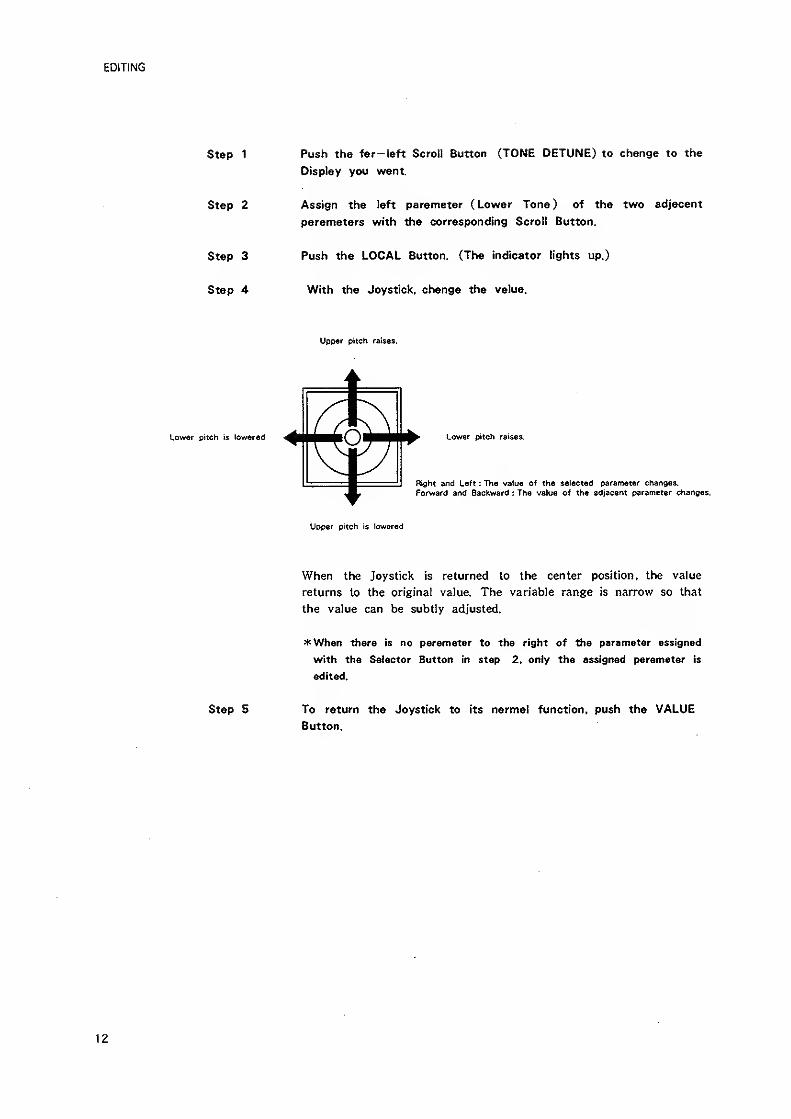
Push the far-left Scroll Button (TONE DETUNE) to change to the
Display you want.
Assign the left parameter ( Lower Tone) of the two adjacent
parameters with the corresponding Scroll Button.
Push the LOCAL Button. (The indicator lights up.)
With the Joystick, change the value.
Upp«r pitch raises.
Lower pitch is low«red
Upper pitch is lowered
When the Joystick is returned to the center position, the value
returns to the original value. The variable range is narrow so that
the value can be subtly adjusted.
*When there is no parameter to the right of the parameter assigned
with the Selector Button in step 2, only the assigned parameter is
edited.
Step 5 To return the Joystick to its narmal function, push the VALUEButton.
Step 1
Step 2
Step 3
Step 4
12
EDITING
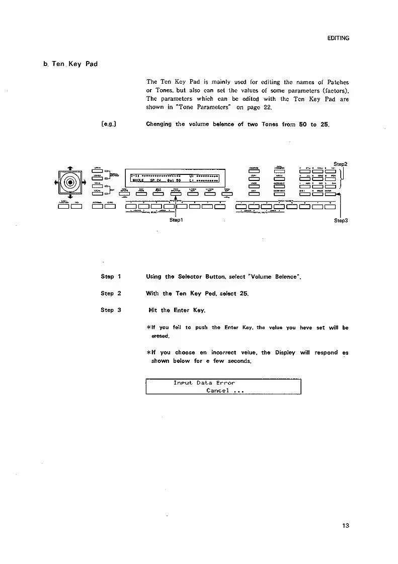
b. Ten Key Pad
The Ten Key Pad is mainly used for editing the names of Patches
or Tones, but also can set the values of some parameters (factors).
The parameters which can be edited with the Ten Key Pad are
shown in "Tone Parameters" on page 22.
[e.g.] Changing the volume balance of two Tones from 50 to 25.
Step2
Step1 Steps
Step 1 Using the Selector Button, select "Volume Balance".
Step 2 With the Ten Key Pad, select 25.
Step 3 Hit the Enter Key.
^If you fait to push the Enter Key, the value you have set will be
erased.
*If you choose an incorrect value, the Display will respond as
shown below for a few seconds.
Input Data ErrorCancel . .
.
13
EDITING
3. USEFUL FUNCTIONS FOR EDITING
a. Compare
While editing a parameter, you may wish to hear the original sound
before it was edited. The D-50's Compare function allows you to
call the original Patch without erasing the edited sound.
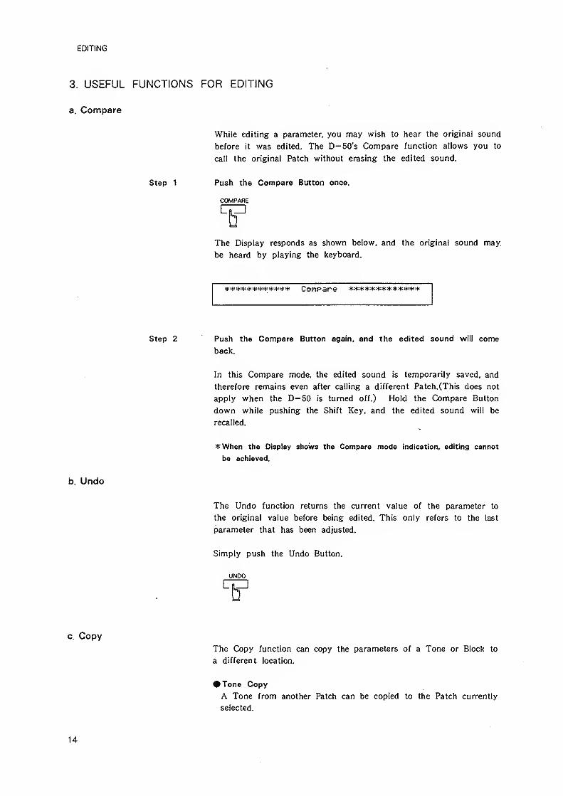
Step 1 Push the Compare Button once.
COMPARE
The Display responds as shown below, and the original sound may
be heard by playing the keyboard.
Step 2 Push the Compare Button again, and the edited sound will come
back.
In this Compare mode, the edited sound is temporarily saved, and
therefore remains even after calling a different Patch.CThis does not
apply when the D— 50 is turned off.) Hold the Compare Button
down while pushing the Shift Key, and the edited sound will be
recalled.
*When the Display shows the Compare mode indication, editing cannot
be achieved.
b. Undo
The Undo function returns the current value of the parameter to
the original value before being edited. This only refers to the last
parameter that has been adjusted.
Simply push the Undo Button.
UNDO
c. CopyThe Copy function can copy the parameters of a Tone or Block to
a different location.
# Tone Copy
A Tone from another Patch can be copied to the Patch currently
selected.
14
EDITING
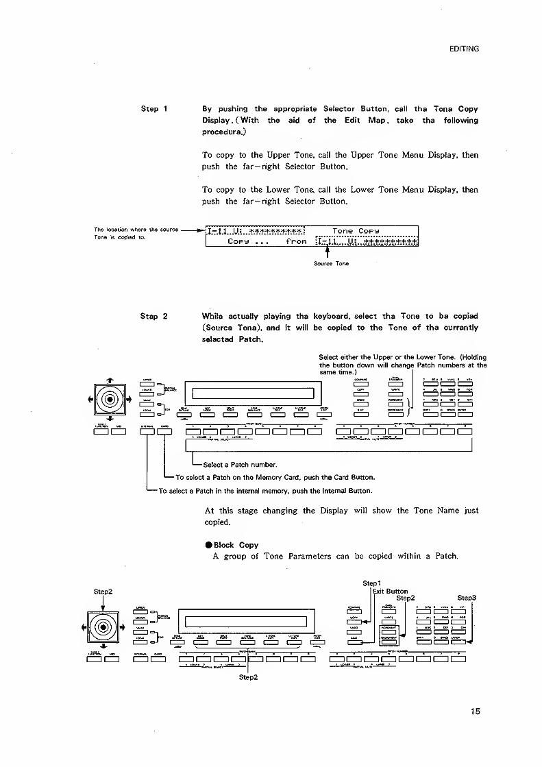
Step 1 By pushing the appropriate Selector Button, call the Tone Copy
Display . ( With the aid of the Edit Map , take the following
procedure.)
To copy to the Upper Tone, call the Upper Tone Menu Display, then
push the far— right Selector Button.
To copy to the Lower Tone, call the Lower Tone Menu Display, then
push the far— right Selector Button.
The location where the source ^ J-Jl IJ: Tone CopyTone is copied to.
Copy . . . fron [i.-ii-.O.:
Source Torie
Step 2 While actually playing the keyboard, select the Tone to be copied
(Source Tone), and it will be copied to the Tone of the currently
selected Patch.
Select either the Upper or the Lower Tone. {Holding
the button down will change Patch numbers at thesame time.)
CZHCIZI CZI en (ZD CZl HZl (ZZl IZD IZZI CZlIZZjCZllZZICZDIZZItZZIIZZI
Select 3 Patch number,
'— To select a Patch on the Memory Card, push the Card Button.
To select a Patch in the internal memory, push the Internal Button.
At this stage changing the Display will show the Tone Name just
copied.
• Block Copy
A group of Tone Parameters can be copied within a Patch.
Step2
i
=J r
Stepi
Exit ButtonStep2
rar
Steps
I 1
I 1
cz) nizzi izz cz] czin 3[ZZliZZ]IZZl CZl CZl CZIiZZ! (ZZliZZl CZi CZl
Step2
15
EDITING
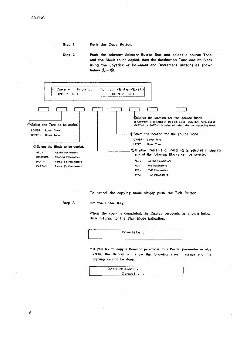
Step 1 Push the Copy Button.
Step 2 Push the relevant Selector Button first, and select a source Tone,
and the Block to be copied, then the destination Tone and its Block
using the Joystick or Increment and Decrement Buttons as shown
below CP - (D.
* Copy * FroM . . . To . ..' <Enter^Exit>
UPPER ALL UPPER RLL
I
©Select the Tone to be copied.
LOWER : Lower Tone
UPPER : Upper Tone
©Select the Block to be copied.
ALL :
COMMON :
PART-1
:
PART -2
;
All the Parameters
Common Parameters
Partial I's Parameters
Partial 2's Paramsters
©Select the location for the source Block.
If COMMON is selected in steo ®. select COMMON here, and if
PART-1 or PART -2 is selected, select the corresponding Sleek.
©Select the location for the source Tone.
LOWER: Lower Tone
UPPER: Upper Tone
_®lf either PART-1 or PART -2 is selected in step
any of the following Blocks can be selected.
ALL :
WG:
TVF :
TVA :
All the Parameters
WG Parameters
TVF Parameters
TVA Parameters
To cancel the copying mode, simply push the Exit Button,
Step 3 Hit the Enter Key.
When the copy is completed, the Display responds as shown below,
then returns to the Play Mode indication.
CoriF-lete .
*If you try to copy a Common parameter to a Partial parameter or vice
versa, the Display will show the following error message and the
copying cannot be done.
Data Mis-fiatoh
Cancel ...
16
EDITING
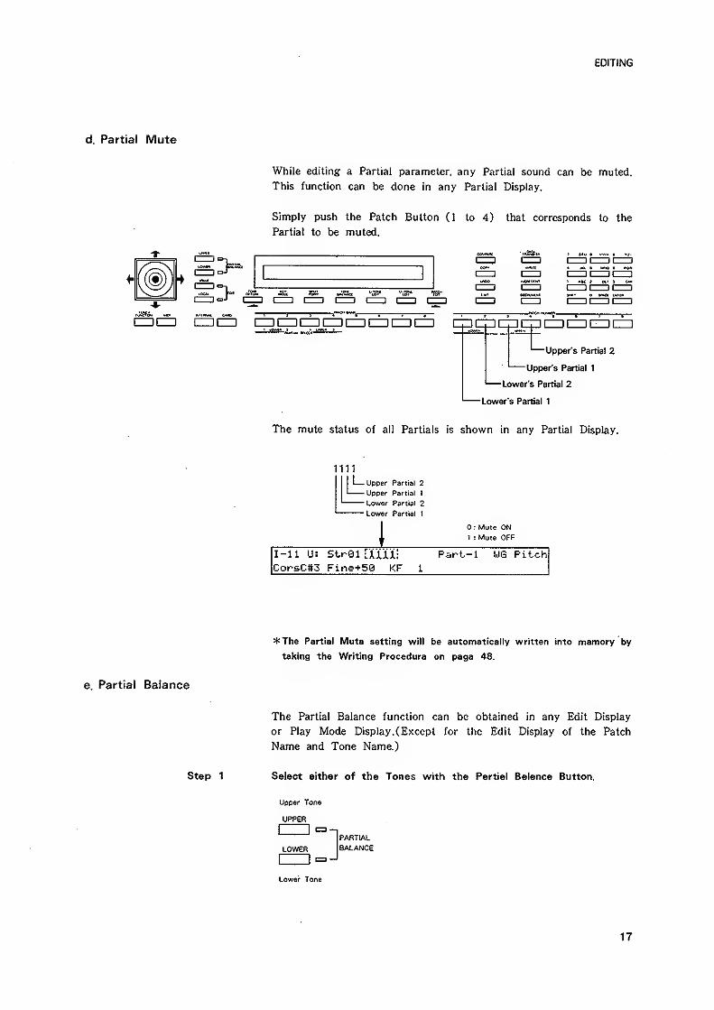
d. Partial Mute
While editing a Partial parameter, any Partial sound can be muted.
This function can be done in any Partial Display,
Simply push the Patch Button (1 to 4) that corresponds to the
Partial to be muled.
1^ czzi 1=) cm nzz3 czzi i=i
'—Upper's Partial 2
-Upper's Partial 1
' Lower's Partial 2
Lower's Partial 1
The mute status of all Partials is shown in any Partial Display.
1111
Upper Partial 2
Upper Partial 1
Lower Partial 2
Lower Partial 1
: Mute ON1 : Mute OFF
I-ll U: StrQl [XiiX: Part-1 WG PitchCorsCtt3 Fine+50 KF 1
*The Partial Mute setting will be automatically written into memory by
taking the Writing Procedure on page 48.
e. Partial Balance
The Partial Balance function can be obtained in any Edit Display
or Play Mode Display. (Except for the Edit Display of the Patch
Name and Tone Name.)
Step 1 Select either of the Tones with the Partial Balance Button.
Upper Tone
UPPER
I i
PARTIAL
LOWER BALANCE
Lower Tone
17
EDITING
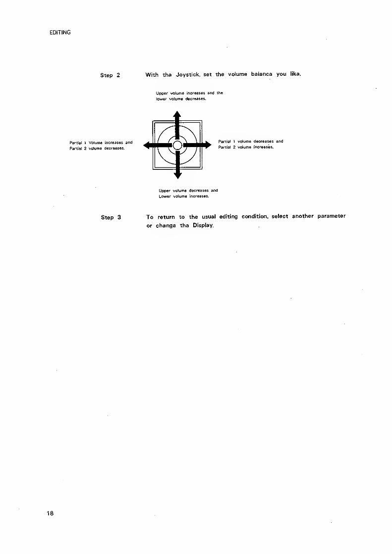
Step 2 With the Joystick, set the volume balance you like.
Uoser volume increases and the
lower volume decreases.
Partial t Volume increases and
Partial 2 volume decreases.
Partial 1 volume decreases and
Partial 2 volume increases.
Upper volume decreases and
Lower volume increases.
Step 3 To return to the usual editing condition, select another parameter
or change the Display,
18
EDITING
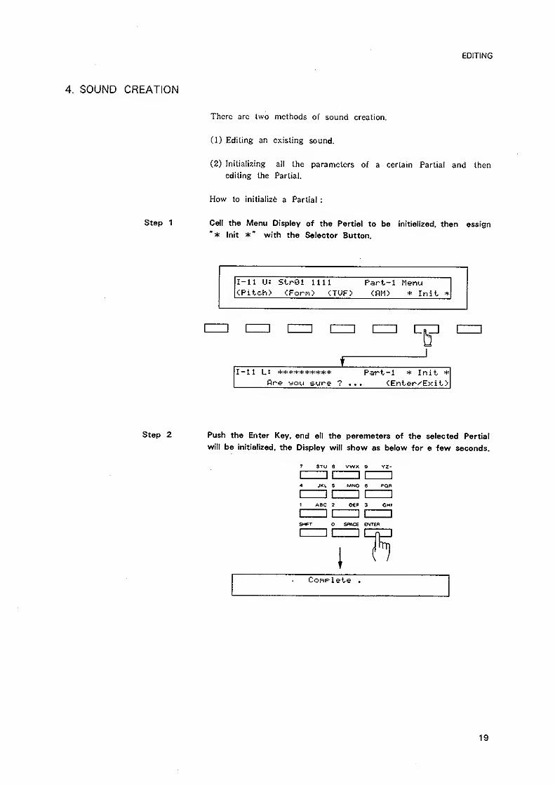
4. SOUND CREATION
There are Iwo methods of sound creation.
(1) Editing an existing sound.
(2) Initializing all the parameters of a certain Partial and then
editing the Partial,
How to initialize a Partial :
Step 1 Call the Menu Display of the Partial to be Initialized, then assign
"* Init *" with the Selector Button.
I-ll U: StrOl 1111 Part-1 Menu|<Piich> clForrO <TUF> <nM> * Init *
!= [= nZD nZD CTD [ZZ]D
^
iI-ll L: Pari-l * Init- *
fire you sure ? ... tEnter^'Exit)
Step 2 Push the Enter Key, and all the parameters of the selected Partial
will be initialized, the Display will show as below for a few seconds.
7 STU 8 VWX 9 Y2-
1 II II 1
4 JKL 5 MNO 6 PQR
1 II II 1
1 ABC 2 OEF 3 GHI
1 II II 1
Sf*T SPOCS ENTER
Conplete .
19
EDITING
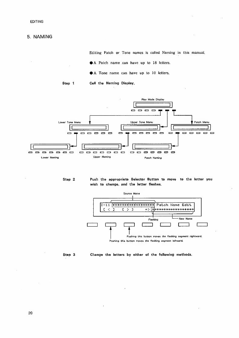
5. NAMING
Step 1
Editing Patch or Tone names is called Naming in this manual.
• A Patch name can have up to 18 letters.
• A Tone name can have up to 10 letters.
Call the Naming Display.
Lower Tone Menu
Play Mode Display
Upper Tone Menu
a t=3 C3 CD 1=1
Lower Naming Upper Naming Patch Naming
Patch Menu
czi C=] CD cu
Step 2 Push the appropriate Selector Button to move to the letter you
wish to change, and the letter flashes.
Source Name
I-ll r***************"^^ Pat-ch Hane Edit,
Flashing New Name
Pushing this button rnoves the flashing segment rightward
Pushing this button moves the flashing segment leftward.
Step 3 Change the letters by either of the following methods.
20
EDITING
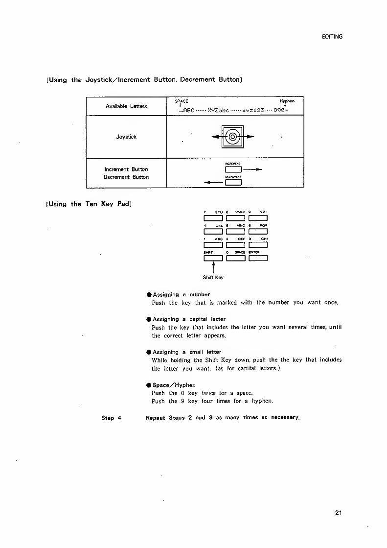
[Using the Joystick/Increment Button, Decrement Button]
Available Letters
SPACEI
-flEC KVZabc
Hyohen4
xyzl23----S90-
Joystick
Increment Button
Decrement Button
ZD
[Using the Ten Key Pad]7 STU 8 VWX 9 YZ-
4 JKL 5 MNO 6 POn
1 ABC 2 OEF 3 GHI
s^*^ o SPACE ENTen
tShift Key
• Assigning a number
Push the key that is marked with the number you want once.
• Assigning a capital letter
Push the key that includes the letter you want several times, until
the correct letter appears.
• Assigning a small letter
While holding the Shift Key down, push the the key that includes
the letter you want, (as for capital letters.)
• Space/Hyphen
Push the key twice for a space.
Push the 9 key four times for a hyphen.
Step 4 Repeat Steps 2 and 3 as many times as necessary.
21
TONE PARAMETERS
TONE PARAMETERS
This section describes ail about the Tone Parameters.
Each Display is numbered as shown in the Edit Map.
*The parameters which can be set with the Ten Key Pad have the 10
key marks as shown below.
10 key
1. COMMON PARAMETERS
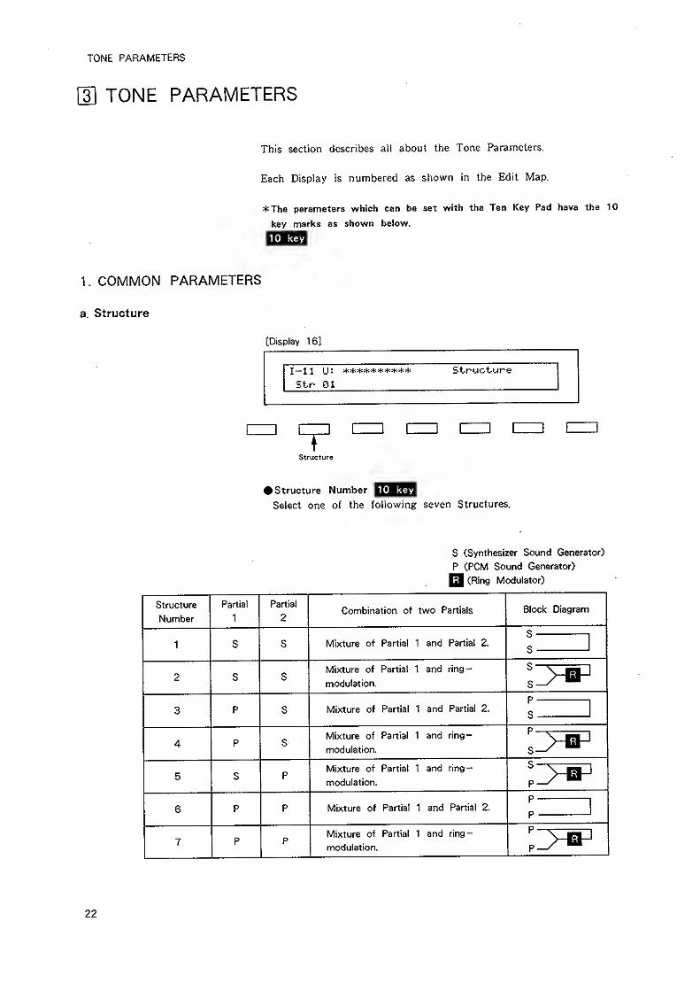
a. Structure
[Display 16]
I-i 1 IJ: ********** Structure
Sir Bl
Structure
• Structure Number |^^^^Select one of the following seven Structures.
S (Synthesizer Sound Generator)
P (PCM Sound Generator)
Q (Ring Modulator)
Structure
Number
Partial
1
Partial
2Combination of two Partials Block Diagram
1 S S Mixture of Partial 1 and Partial 2.
s1
S
2 S SMixture of Partial 1 and ring-
modulation.
3 P s Mixture of Partial 1 and Partial 2.
p
s
4 P sMixture of Partial 1 and ring-
modulation.
5 S pMixture of Partial 1 and ring-
modulation.
6 P p Mixture of Partial 1 and Partial 2.
p
p
7 P pMixture of Partial 1 and ring-
modulation.
22
3
TONE PARAMETERS
[Display 17]
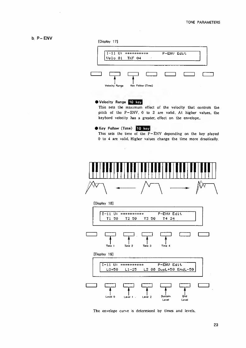
I-U U: 't" 't* "t" -4^^^^^ if! P-EHM EditUelo 81 TKF 04
r tVelocky Range Key Follow (Time)
10 keyt Velocity Range
This sets the maximum effect of the velocity that controls the
pitch of the P-ENV. to 2 are valid. At higher values, the
keybord velocity has a greater, effect on the envelope..
10 key#Key Follow (Time)
This sets the time of the P—ENV depending on the key played
to 4 are valid. Higher values change the time more drastically.
[Display 18]
I-ll U: P-ENU EditTl 50 T2 50 T3 50 T4 24
T T T TTime ] Time 2 Time 3 Time 4
[Display 19]
I-ll U : P-EHU Ed i t
LO+50 Ll-25 L2 08 SusL+50 EndL-50
r T T T 1Level Level I . Level 2 Sustain
Level
End
Level
The envelope curve is determined by times and levels.
23
TONE PARAMETERS
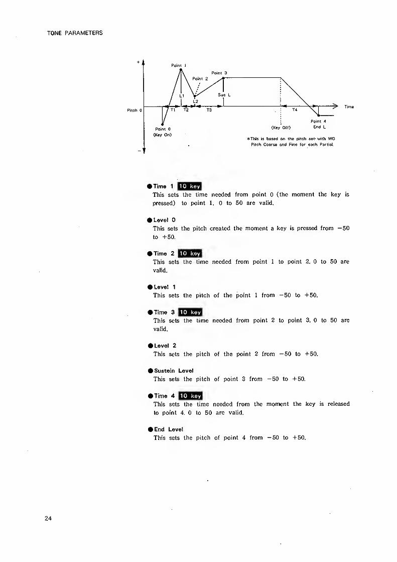
Point 1
Pitch
Point 3
Sus L
^ Time
(Key Off)
*This is based on the pitch set- with WOPitch Coarse and Fine for each Partial.
10 keyTime 1
This sets the time needed from point (the moment the key is
pressed) to point 1. to 50 are valid.
• Level
This sets the pitch created the moment a key is pressed from -50
to +50.
10 keyKime 2
This sets the time needed from point 1 to point 2. to 50 are
valid.
• Level 1
This sets the pitch of the point 1 from -50 to +50.
10 key>Time 3
This sets the lime needed from point 2 to point 3. to 50 are
valid.
• Level 2
This sets the pitch of the point 2 from ~50 to +50.
• Sustain Level
This sets the pitch of point 3 from -50 to +50.
• Time 4 EQH^yjThis sets the time needed from the moment the key is released
to point 4. to 50 are valid.
• End Level
This sets the pitch of point 4 from —50 to +50.
24
TONE PARAMETERS
*lf the Levels of two adjacent points are set to simitar values, the
time between these two points may prove to be shorter than what
is actually set, or even zero.
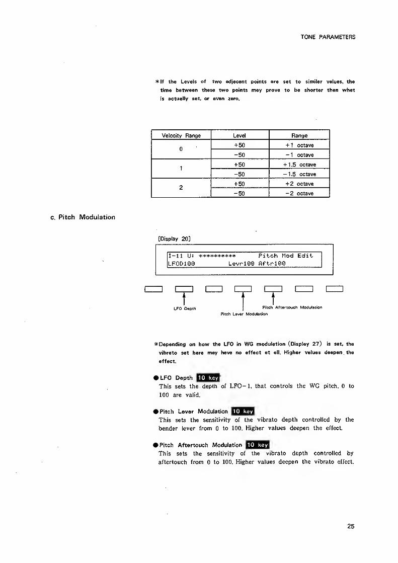
Velocity Range Level Range
+50 + 1 octave
-50 - 1 octave
1
+50 + 1.5 octave
-50 -1.5 octave
2+ 50 + 2 octave
-50 -2 octave
c. Pitch Modulation
[Display 20]
I-ll iJ: Pitch Mod EditLFODiee Levriee flftrie©
LFO Depth Pitch Aftertouch Modulation
Pitch Lever Modulation
* Depending on how the LFO in WG modulation (Display 27) is set, the
vibrato set here may have no effect at all. Higher values deepen . the
effect.
10 keyLFO Depth
This sets the depth of LFO-1, that controls the WG pitch. to
100 are valid.
10 keyPitch Lever Modulation
This sets the sensitivity of the vibrato depth controlled by the
bender lever from to 100. Higher values deepen the effect.
10 keyPitch Aftertouch Modulation
This sets the sensitivity of the vibrato depth controlled by
aftertouch from to 100, Higher values deepen the vibrato effect.
25
[Display 21 -23]
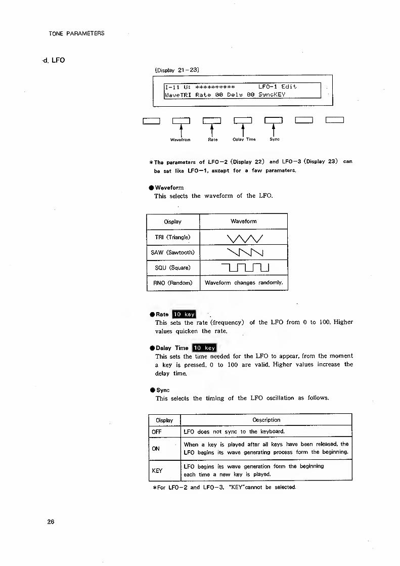
I-ll IJ: ********** LFO-1 Edit.
ijJayeTRI Rate QQ Dely 96 S^ncKEV
T T T TWavefrom Rate Delay Time Sync
*The parameters of LFO—2 (Display 22) and LFO-3 (Display 23) can
be set Mice LFO— 1, except for a few parameters.
# Waveform
This selects the waveform of the LFO.
Display Waveform
TRI (Triangle) \AA/SAW (Sawtooth)
SOU (Square)
RND (Random) Waveform changes randomly.
• Rate iQ^SThis sets the rate (frequency) of the LFO from to 100. Higher
values quicken the rate.
• Delay Time ^^^^QThis sets the time needed for the LFO to appear, from the moment
a key is pressed. to 100 are valid. Higher values increase the
delay time,
• Sync
This selects the timing of the LFO oscillation as follows.
Display Description
OFF LFO does not sync to the keyboard.
ONWhen a key is played after all keys have been released, the
LFO begins its wave generating process form the beginning.
KEYLFO begins its wave generation form the beginning
each time a new key is played.
*For LFO-2 and LFO-3, "KEY"cannot be selected.
TONE PARAMETERS
e. Equalizer
[Display 24]
r r r r ^Lf La Hf HQ Ha
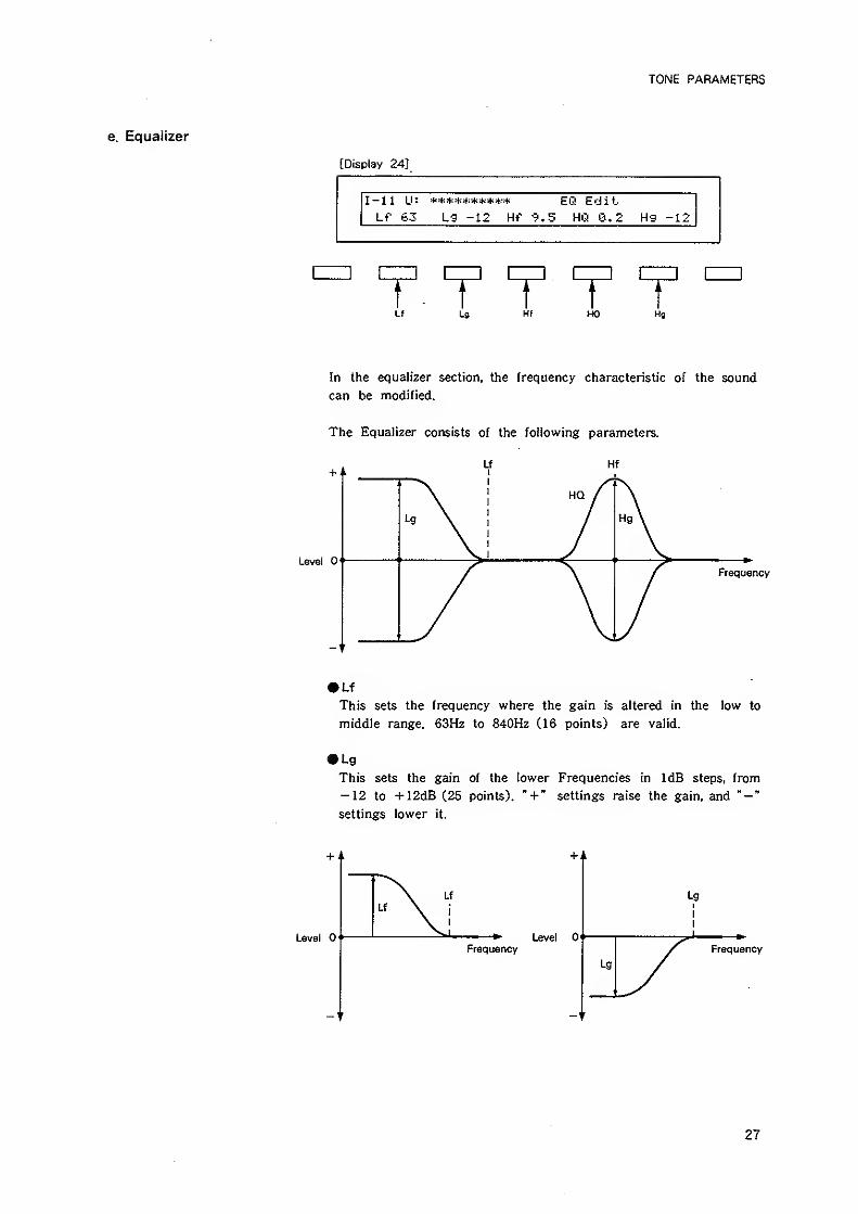
In the equalizer section, the frequency characteristic of the sound
can be modified.
• Lf
This sets the frequency where the gain is altered in the low to
middle range. 63H2 to 840H2 (16 points) are valid.
• Lg
This sets the gain of the lower Frequencies in IdB steps, from
— 12 to +12dB (25 points). " + " settings raise the gain, and "-"
settings lower it.
27
TONE PARAMETERS
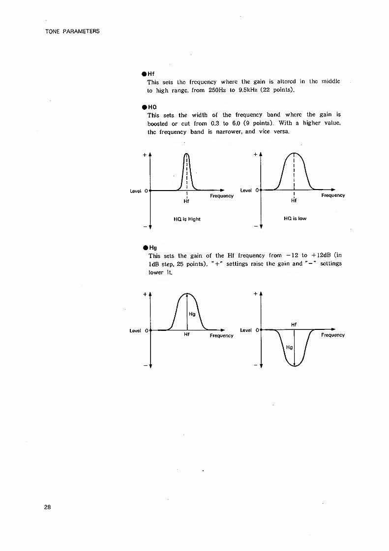
• Hf
This sets the frequency where the gain is altered in Iho middle
to high range, fronn 250H2 to 9.5kHz (22 points).
• HQThis sets the width of the frequency band where the gain is
boosted or cut from 0.3 to 6.0 (9 points). With a higher value,
the frequency band is narrower, and vice versa.
!Frequency
Hf
HQ is low
Level 0< Level
Hf
Frequency
HQ is Hight
• Hg
This sets the gain of the Hf frequency from -12 to +12dB (in
IdB step, 25 points). " + " settings raise the gain and " — " settings
lower it.
Frequency
28
TONE PARAMETERS
[Display 25]
I-ll U: Chorus EditType 01 Rate 50 Opth 50 Bal 56
T T T T "
Chorus Type Chorus Rate Chorus Depth Chorus Balance
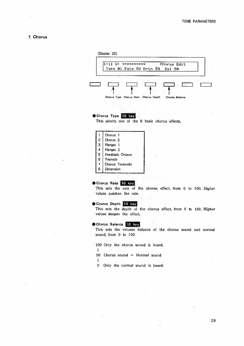
10 keyk Chorus Type
This selects one of the 8 basic chorus effects.
1 Chorus 1
2 Chorus 2
3 Flanger 1
4 Flanger 2
5 Feedback Chorus
6 Tremolo
7 Chorus Toremolo
8 Dimension
10 key» Chorus Rate
This sets the rate of the chorus effect, from to 100. Higher
values quicken the rate.
10 keyft Chorus Depth
This sets the depth of the chorus effect, from to 100. Higher
values deepen the effect.
10 keyft Chorus Balance
This sets the volume balance of the chorus sound and normal
sound, from to 100.
100 Only the chorus sound is heard.
}
50 Chorus sound = Normal sound
}
Only the normal sound is heard.
29
TONE PARAMETERS
2. PARTIAL PARAMETERS
[Restriction of the available parameters caused by Structure]
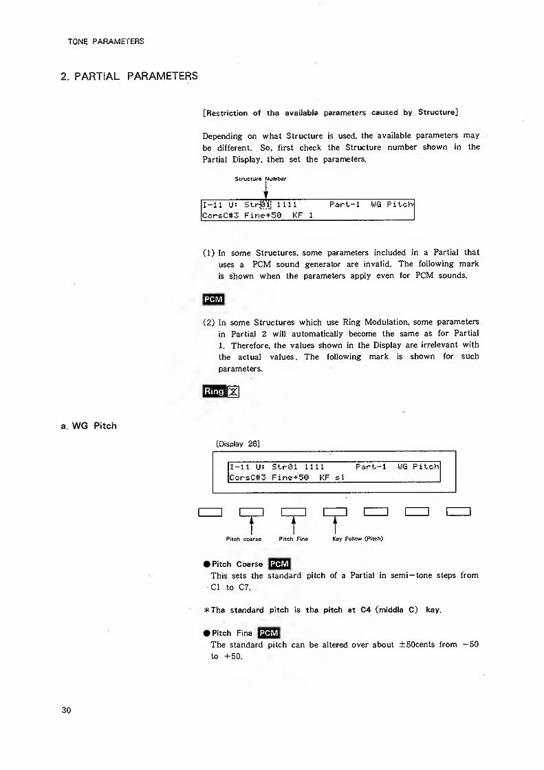
Depending on what Structure is used, the available parameters may
be different. So, first check the Structure number shown in the
Partial Display, then set the parameters.
Structure Number
I,
I-ll U: Str^lj 1111 Part-1 WG Pitch
Cor£C#3 Fine+50 KF 1
a. WG Pitch
(1) In some Structures, some parameters included in a Partial that
uses a PCM sound generator are invalid. The following mark
is shown when the parameters apply even for PCM sounds.
(2) In some Structures which use Ring Modulation, some parameters
in Partial 2 will automatically become the same as for Partial
1. Therefore, the values shown In the Display are irrelevant with
the actual values. The following mark is shown for such
parameters.
[Display 26]
1=1 [
r T 1Pitch coarse Pitch Fine Key Follow (Pitch)
• Pitch Coarse yQ23This sets the standard pitch of a Partial in semi— tone steps from
CI to C7.
*The standard pitch is the pitch at C4 (middle C) key.
• Pitch Fine |^J^The standard pitch can be altered over about ±50cents from -50
to +50.
30
TONE PARAMETERS
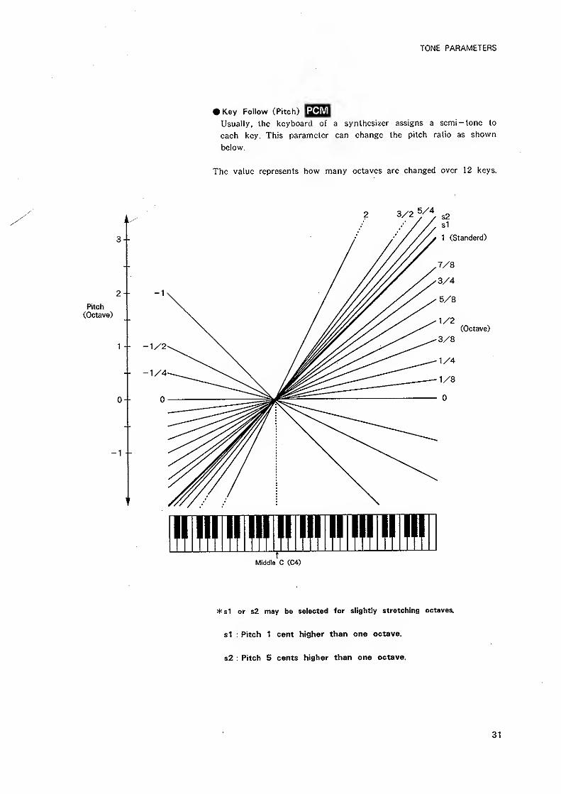
• Key Follow (Pitch)
Usually, the keyboard of a synthesizer assigns a semi-lone lo
each key. This parameter can change the pitch ratio as shown
below.
The value represents how many octaves arc changed over 12 keys.
3/2 V\ s2
3--
2-Pitch
(Octave)
0--
-1 -
rMiddle C CC4)
Sl
1 (Standerd)
(Octave)
*s1 or s2 may be setected for slightly stretching octaves,
si : Pitch 1 cent higher than one octave.
s2 : Pitch 5 cents higher than one octave.
31
TONE PARAMETERS
b. WG Modulation
[Display 27]
I-il U: Strei nil Part-1 WS ModLFO fiSiL EHU <-> BendNOM
r T 1LFO Mod© P-ENV Mode Pitch B«nder Mode
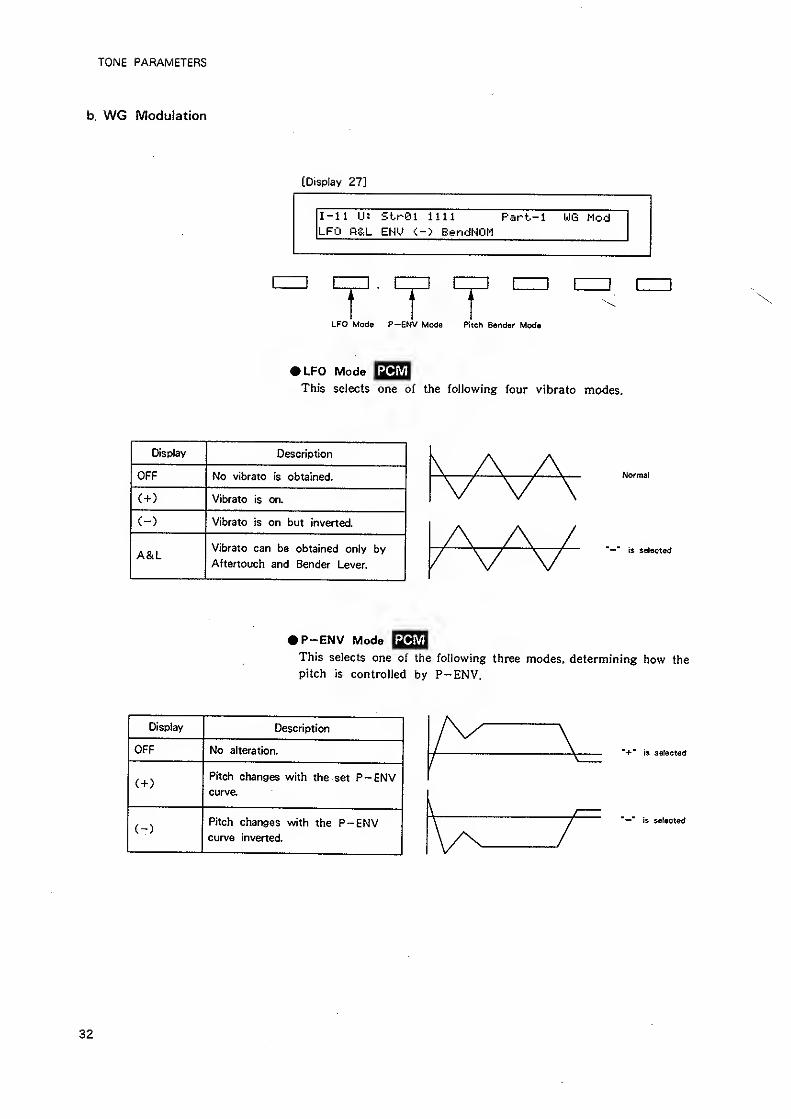
»LFO ModeThis selects one of the following four vibrato modes.
Display Description
OFF No vibrato is obtained.
C+) Vibrato is on.
C-) Vibrato is on but inverted.
A&LVibrato can be obtained only by
Aftertouch and Bender Lever.
Normal
'—" is selected
• P-ENV Mode I^QIThis selects one of the following three modes, determining how the
pitch is controlled by P-ENV.
Display Description
OFF No alteration.
( + )
Pitch changes with the set P-ENVcurve.
Pitch changes with the P-ENVcurve inverted.
"+" is selected
"-"is selected
32
TONE PARAMETERS
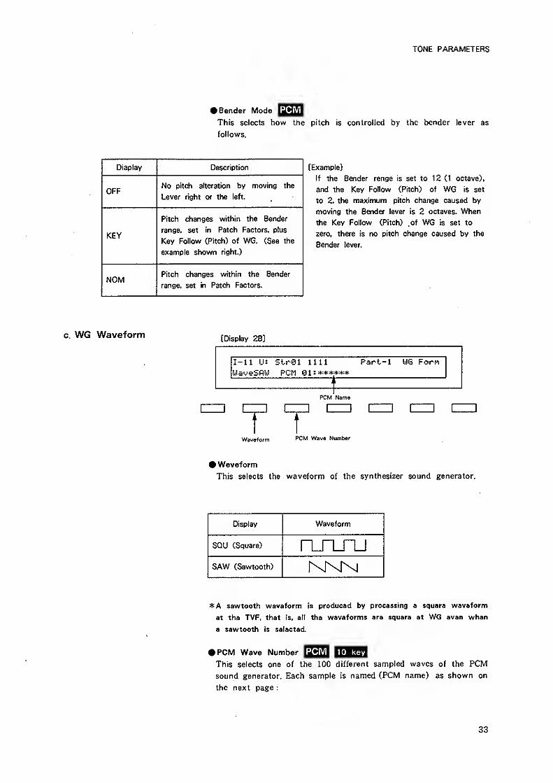
# Bender Mode ySZuThis selects how Ihe pitch Is controlled by the bender lever as
follows.
Diaplay Description
OFFNo pitch alteration by moving the
Lever right or the left.
KEY
Pitch changes within the Bender
range, set in Patch Factors, plus
Key Follows (Pitch) of WG. (See the
example shown right.)
NOMPitch changes within the Bender
range, set in Patch Factors.
[Example]
if the Bender renge is set to 12 (1 octave),
and the Key Follow (Pitch) of WG is set
to 2, the maximum pitch change caused by
moving the Bender lever is 2 octaves. When
the Key Follow (Pitch) .of WG is set to
zero, there is no pitch change caused by the
Bender lever.
c. WG Waveform[Display 28]
I-U U: Sirei 1111 Part-1 WG FornUaveSflW PCM 91
PCM Name
r 1Waveform PCM Wave Number
# Waveform
This selects the waveform of the synthesizer sound generator.
Display Waveform
SOU (Square) n_m~uSAW (Sawtooth)
^A sawtooth waveform is produced by processing a square waveform
St the TVF, that is, all the waveforms are square at WG even when
a sawtooth is selected.
• PCM Wave Number [Q^SThis selects one of the 100 different sampled waves of the PCMsound generator. Each sample is named (PCM name) as shown on
the next page :
33
TONE PARAMETERS
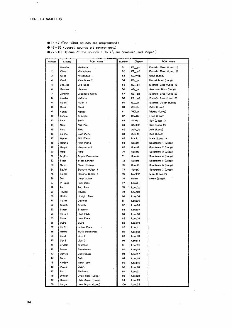
#1~47 (One -Shot sounds are programmed.)
• 48'-76 (Looped sounds are programmed.)
#77—100 (Some of the sounds 1 to 76, are combined and looped.)
Number Display PCM Name Number Display PCM Name
1 Marmba Marimba 51 EP_lpl Electric Piano (Loop 1) .
2 Vibes Vibraphone 52 EP_lp2 Electric Piano (Loop 2)
3 Xylol Xylophone I 53 CLAVlp Clavi (Loop)
4 Xylo2 Xylophone 2 54 HC_lp Harpsichord (Loop)
5 L09_Bs Log Bass 55 EB_lp1 Electric Bass (Loop 1)
6 Hammer Hammer 56 AB_tp Acoustic Bass (Loop)
7 JpnDrm Japanese Drum 57 EB_lp2 Electric Bass (Loop 2)
8 Kalmba Kalimba 58 EB_lp3 Electric Bass (Loop 3)
9 Pluokl Pluck 1 59 EG_lp Electric Guitar (Loop)
10 Chink Chink 60 CELLIp Cello (Loop)
It Agogo Agogo 61 VIOLIp Violine (Loop)
12 3angle Triangle 62 Reedip Leed (Loop)
13 Sells Bell's 63 SAXlpI Sax (Loop
14 Nails Nail File 64 SAXIp2 Sax (Loop 2)
15 Pick Pick 65 Aah_lp Aah (Loop)
16 Lpiano Low Piano 66 Ooh Ip Ooh (Loop)
17 Mpiano Mid Piano 67 Manlpl Male (Loop 1)
18 Kpiano High Piano 68 Specti Spectrum 1 (Loop)
19 Harpsi Harpsichord 69 Spect2 Spectrum 2 (Loop)
20 Harp Harp 70 Spect3 Spectrum 3 (Loop)
21 OrgPrc Organ Percussion 71 Speot4 Spectrum 4 (Loop)
22 Steel Steel Strings 72 Spect5 Spectrum 5 (Loop)
23 Nylon Nylon Strings 73 Specte Spectrum 6 (Loop)
24 Eguitt Electric Guiter 1 74 Spect? Spectrum 7 (Loop)
25 Esuit2 Electric Guitar 2 75 Mantp2 Mai© (Loop 2)
26 Dirt Dirty Guitar 76 Noise Noise (Loop)
27 P_Bass Pick 8ass 77 LoopOl
28 Pop Pop Bass 78 Loop02
29 Thump Thump 79 Loop03
30 Uprite Upright 8ass 80 Loop04
31 Clarnt Clarinet 81 Loop05
32 Breath Breath 82 LoopOe
33 Steam Steamer 83 Loop07
34 FluteH High Flute 84 LoopOS
35 FlutoL Low Flute 85 LoopOS
36 Guiro Guiro 86 LooplO
37 IndFIt Indian Fluta 87 Loop!
1
38 Harmo Flute Harmonics 88 Loopt2
39 Lips I Lips 1 89 Loop I
3
40 Lips2 Lips 2 90 Loop14
41 Trumpt Trumpet 91 Loop 1
5
42 Bones Trombones 92 Loop 16
43 Contra Contrabass 93 Loopl7
44 Cello Cello 94 Loop IS
45 VioBow Violin Bow 95 Loop 19
46 Violns Violins 96 Loop20
47 Pizz Pizzicart 97 Loop2l
48 Drawbr Draw bars (Loop) 98 Loop22
49 Morgan High Organ (Loop) 99 Loop23
50 Lorgan Low Organ (Loop) 100 LOOD24
34
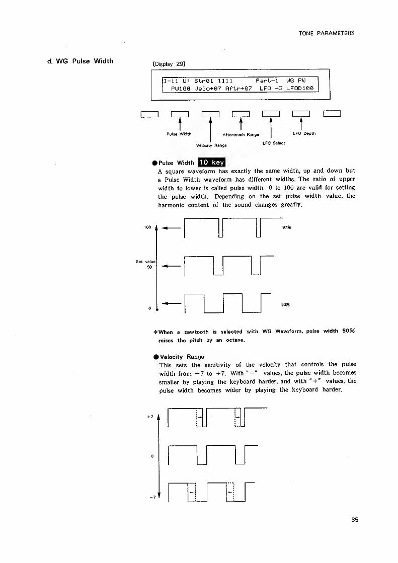
TONE PARAMETERS
d. WG Pulse Width[Display 29]
Pulse Width Aftertouch Range LFO Depth
Velocity RangeLFO Select
10 keyPulse Width
A square waveform has exactly the same width, up and down but
a Pulse Width waveform has different widths. The ratio of upper
width to lower is called pulse width. to 100 are valid for setting
the pulse width. Depending on the set pulse width value, the
harmonic content of the sound changes greatly.
100 9796
Set value
50
5096
*When a sawtooth is selected with WG Waveform, pulse width 50%
raises the pitch by an octave.
• Velocity Range
This sets the senitivity of the velocity that controls the pulse
width from -7 to +7. With values, the pulse width becomes
smaller by playing the keyboard harder, and with " + " values, the
pulse width becomes wider by playing the keyboard harder.
35
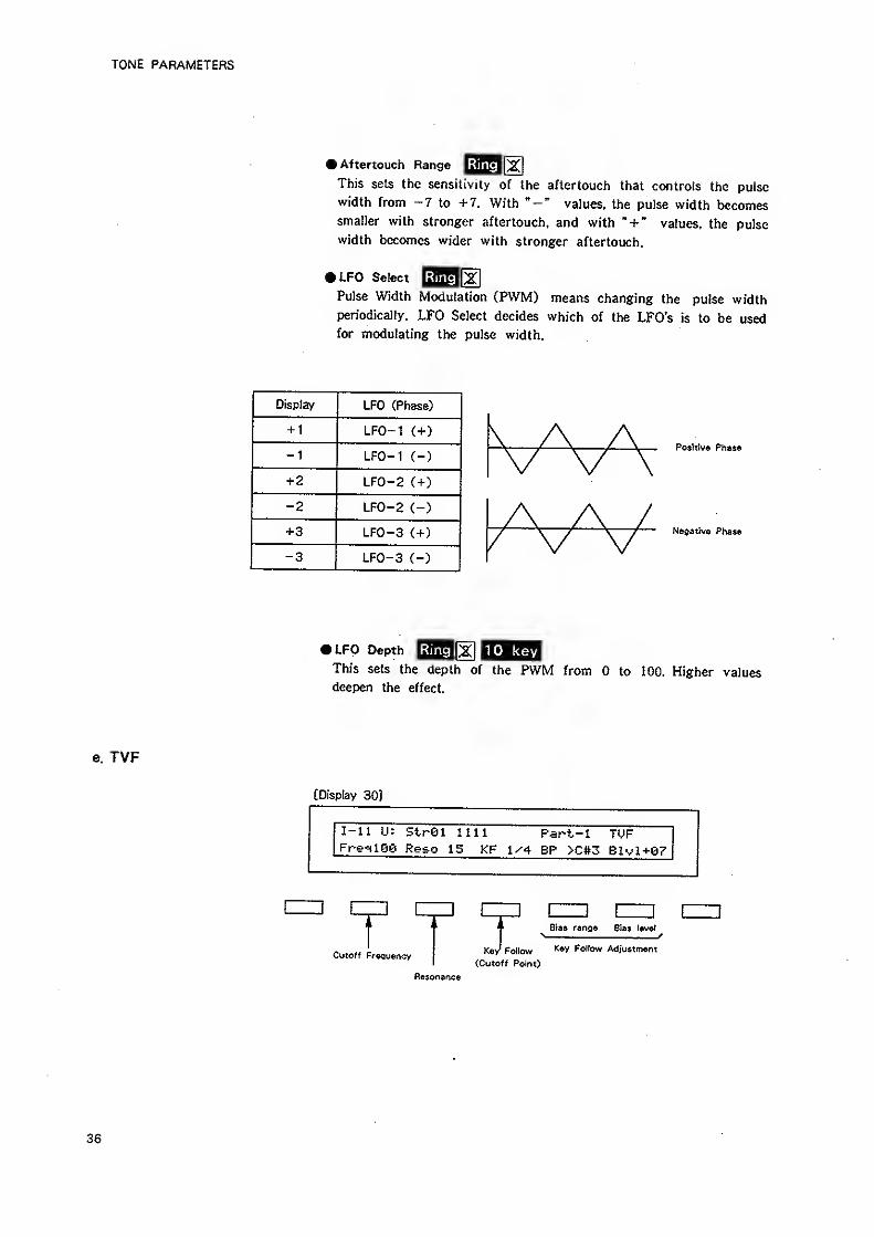
TONE PARAMETERS
^Aftertouch Range ^^^[XThis sets the sensilivity of the aftertouch that controls the pulse
width from -7 to +7. With values, the puise width becomessmaller with stronger aftertouch, and with "+ * values, the pulse
width becomes wider with stronger aftertouch.
ISUFO Select|j
Pulse Width Modulation (PWM) means changing the pulse width
periodically. LFO Select decides which of the LFO's is to be usedfor modulating the pulse width.
Display LFO (Phase)
+ 1 LFO-1 (+)
-1 LFO-1 (-)
+2 LFO-2 C+)
-2 LFO-2 (-)
+3 LFO-3 C+)
-3 LFO-3 (-)
Positive Phase
Negative Phase
UFO Depth Ring railO keyThis sets the depth of the PWM from to 100. Higher values
deepen the effect.
e. TVF
[Display 30]
I-ll U: StrSl nil Part-1 TUFFrg'iige Reso 15 KF 1^4 BP >C#3 Blvl+07
1 [
Cutoff Frequency IBras range Bias level
Key* Pollow '^•i' Fol'ow Adjustment
(Cutoff Point)
Resonance
36
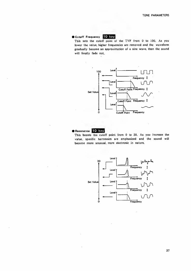
TONE PARAMETERS
• Cutoff Frequency
This sets the cutoff point of the TVF from to 100. As you
iower the value, higher frequencies arc removed and the waveform
gradually become an approximation of a sine wave, then the sound
will finally fade out.
100
Set Value
Level
I
Level
Level
^^^^^ mnFrequency t
Cutoff Point Frequency t
Level
Cutoff Point Frequency t
Cutoff Point Frequency
• Resonance |^jpia*i
This boosts the cutoff point from to 30. As you increase the
value, specific harmonics are emphasized and the sound will
become more unusual, more electronic in nature.
30
Set Value
Level
Level
Level
Level
'
Frequency|
—lJ ^Frequency
J
Frequency (
Frequency
37
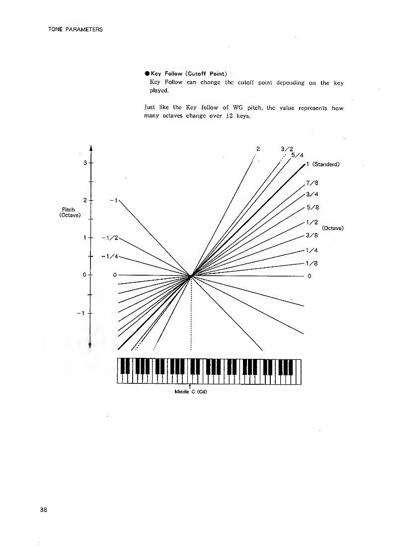
TONE PARAMETERS
-1 --
• Key Follow (Cutoff Point)
Key Follow can change the cutoff point depending on the key
played.
Just like the Key follow of WG pitch, the value represents howmany octaves change over 12 keys.
3/2
3--
2-Pitch
(Octave)
1 - -
0--
5/4
/ // y^ (Standerd)
/ // X /^^^
/ /// Xy^^^-K
/ /// ^5/8
/ ////x X"^^ ^1/2/ //XXX X^ ^^^^ (Octave)
1/2^ \ /^ -1/8
rMiddle C CC4)
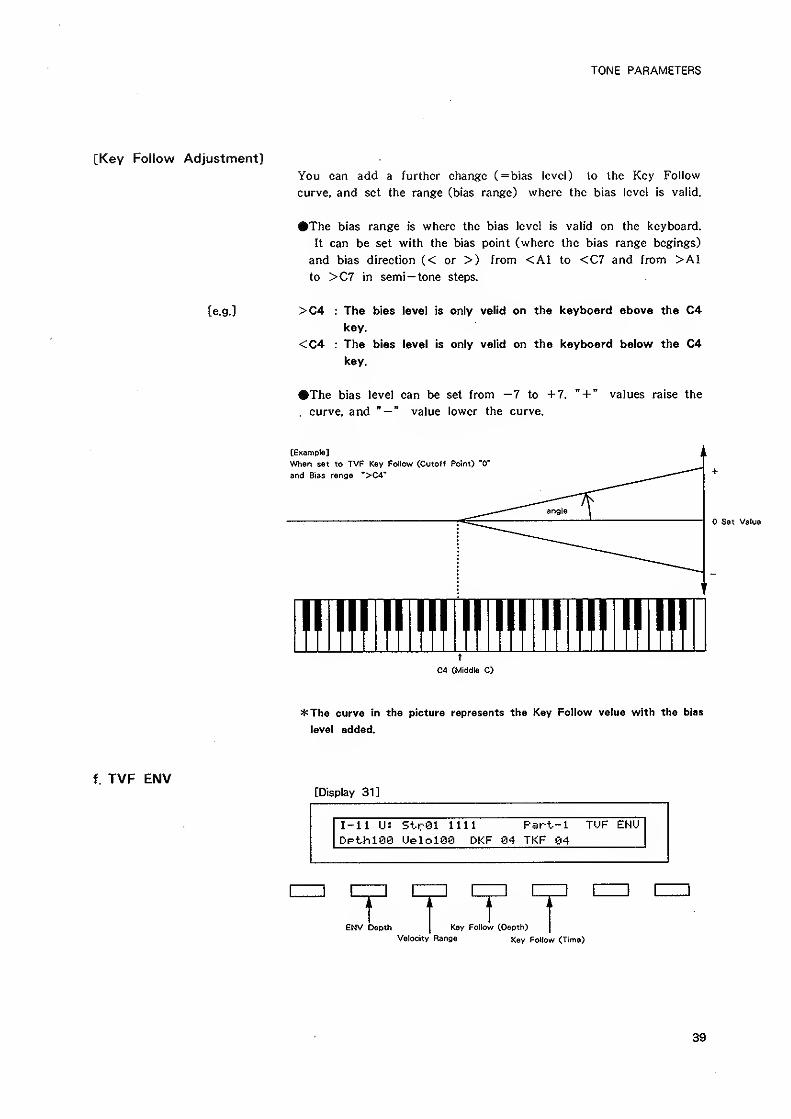
TONE PARAMETERS
[Key Follow Adjustment]
You can add a further change C=bias level) lo the Key Follow
curve, and set the range (bias range) where the bias level is valid.
•The bias range is where the bias level is valid on the keyboard.
It can be set with the bias point (where the bias range begings)
and bias direction (< or >) from <A1 to <C7 and from >A1
to >C7 in semi— tone steps.
[e.g.] >C4 : The bias level is only valid on the keyboard above the C4
key,
<C4 : The bias level is only valid on the keyboard below the C4
key.
•The bias level can be set from -7 to +7. " + " values raise the
. curve, and "— " value tower the curve.
[Example]
When set to TVF Key Follow (Cutoff Point) "0'
and Bias renge ">04"
Set Value
!!II!!I>HIIII!HII!II!I1!!I!II!!!t
04 (Middle C)
*The curve in the picture represents the Key Follow value with the bias
level added.
f. TVF ENV[Display 31]
I-ll U: Strei 1111 Part-l TUF ENU
Dpthiee UeloiSQ DKF 64 TKF 04
ENV Depth Key Follow (Depth)
Velocity Range Key Follow (Time)
39
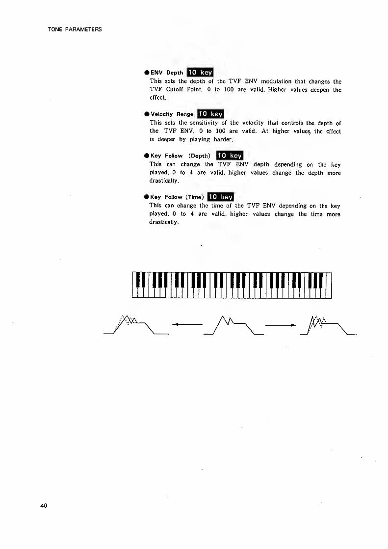
TONE PARAMETERS
10 key»ENV Depth
This sets the depth of the TVF ENV modulation that changes the
TVF Cutoff Point. to 100 are valid. Higher values deepen the
effect.
10 key» Velocity Range
This sets the sensitivity of the velocity that controls the depth of
the TVF ENV. to 100 are valid. At higher values, the effect
is deeper by playing harder.
10 keyKey Follow (Depth)
This can change the TVF ENV depth depending on the key
played. to 4 are valid, higher values change the depth more
drastically.
10 keyKey Follow (Time)
This can change the time of the TVF ENV depending on the key
played. to 4 are valid, higher values change the time more
drastically.
fl III 1milmilmilnil
40
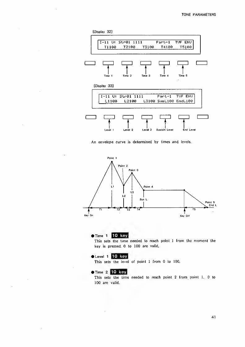
TONE PARAMETERS
(Display 32]
I-U U: StrSl nil Part-1 TUF EHU
T1100 T2100 jzim T410G1 T510@
r T 7Time 1 Time 2 Time 3 Time A Time 5
[Display 33]
I-ll IJ: Strei nil Part-l TUF ENULllSS L2100 L3100 SusL100 EndL10Q
r T 1Level 1 Level 2 Level 3 Sustain Level End Level
An envelope curve is determined by times and levels.
Point 1
Point 2
Point 3
Point 4
Sus L
Key Off
10 key• Time 1
This sets the time needed to reach point 1 from the moment the
key is pressed. to 100 are valid.
» Level 1
This sets the level of point 1 from to 100.
10 key
10 key• Time 2
This sets the time needed to reach point 2 from point 1. to
100 are valid.
41
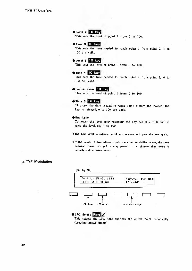
TONE PARAMETERS
10 key» Level 2
This sets the level of point 2 from to 100.
10 keyHime 3
This sets the time needed to reach point 3 from point 2, to
100 are valid.
10 key• Level 3
This sets the level of point 3 from to 100.
10 keyTime 4
This sets the time needed to reach point 4 from point 3. to
100 are valid.
10 key» Sustain Level
This sets the level of point 4 from to 100.
10 keyTime 5
This sets the time needed to reach point 5 from the moment the
key is released. to 100 are valid.
#End Level
To lower the level after releasing the key, set this to 0, and to
raise the level, set it to 100.
*Th6 End Level is retained until you release and play the key again.
*lf the Levels of two adjacent points are set to similar values, the time
betvi/een these two points may prove to b© shorter than what is
actually set, or even zero.
g. TVF Modulation
[Display 34]
1-11 U: Strei 1111LFO -3 LFOD100
Part-1 TUF Hodftftr-S7
T TLFO Select LFO Depth Aftertouch Range
• LFO Select iHlglry
This selects the LFO that changes the cutoff point periodically
(creating growl effects).
42
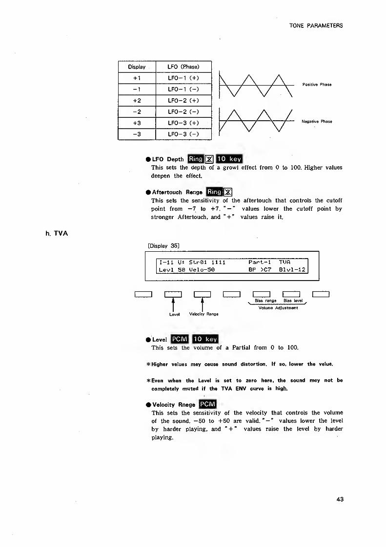
TONE PARAMETERS
LFO fPha-^e^
+ 1 LFO-1 (+)
-^ LFO-1 C-)
+ 2 LFO-2 (+)
-2 LFO-2 (-)
+3 LFO-3 (+)
-3 LFO-3 (-)
Po sifive Phase
Negative Phase
Ring rail key»LFO Depth
This sets the depth of a growl effect from to 100. Higher values
deepen the effect.
^Aftertouch Range |yThis sets the sensitivity of the aftertouch that controls the cutoff
point from —7 to +7, " — " values lower the cutoff point by
stronger Aftertouch, and " + " values raise it.
[Display 35]
I-ll U: Str01 UU Part-1 TUfl
Levi 50 Uelo-50 BP >C7 Blvl-12
r 1 ^ Bias range Bias tev
Volume Adjustment
Level Velocity Range
PCM 1 10 keyLevel
This sets the volume of a Partial from to 100.
* Higher values may cause sound distortion. If so, lower the value.
4: Even when the Level Is set to zero here, the sound may not be
completely muted if the TVA ENV curve is high.
# Velocity Rnage
This sets the sensitivity of the velocity that controls the volume
of the sound. —50 to +50 are valid." — " values lower the level
by harder playing, and " + " values raise the level by harder
playing.
43
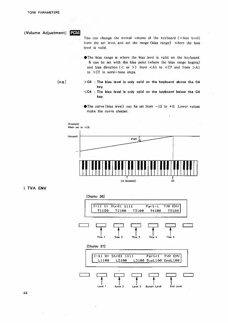
TONE PARAMETERS
[Volume Adjustment]
You can change the overall volume of the keyboard ( = bias level)
from Ihc set level, and set the range (bias range) where the bias
level is valid.
#The bias range is where the bias level is valid on the keyboard.
It can be set with the bias point (where the bias range begins)
and bias direction (< or >) from <A1 to <C7 and from >A1to >C7 in semi— tone steps.
[e.g.] >C4 : The bias level is only valid on the keyboard above the C4key.
<C4 : The bias level is only valid on the keyboard below the C4key.
The curve (bias level) can be set from —12 to +0. Lower values
make the curve steeper.
i. TVA ENV
[ExampleJ
When set to <C6.
VolumeO
!fll!!l!!i!!ll!!lllllllll!ll!fT
a (MiddteC) C6
[Display 36]
I-il U: StrSl 1111 Part-1 TUPI EHUTiiee T2100 T3190 T4100 T5i0f3
r 1Time 1 , Time 2 Time 3 Time 4 Time 5
[Display 37]
I-n U: StrSl nil Part-l TUfl EHUL1100 L2100 L3100 Su&Liee EridL100
] izz:
r T T 1l^evel 1 Level 2 Level 3 Sustain Level End Level
44
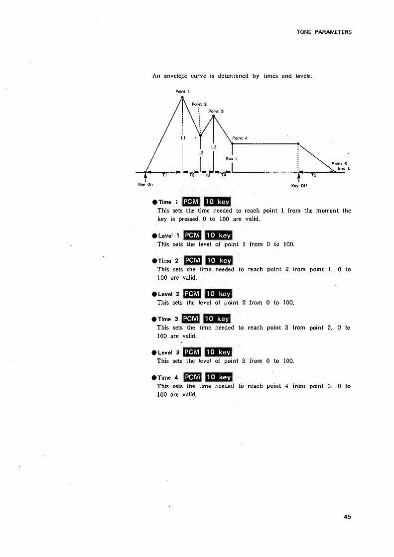
TONE PARAMETERS
An envelope curve is determined by limes and levels.
Point I
Point 2
Point 3
Point A
Sus L
Key On
T2 T3 T4
PCiVl|lO key• Time 1
This sets the time needed to reach point 1 from the moment the
key is pressed. to 100 are valid.
PCM 1 10 key» Level 1
This sets the level of point 1 from to 100.
PCM 1 10 keyKIme 2
This sets the time needed to reach point 2 from point 1. to
100 are valid.
PCMllO key• Level 2
This sets the level of point 2 from to 100.
PCMllO key• Time 3
This sets the time needed to reach point 3 from point 2. to
100 are valid.
PCMllO keyft Level 3
This sets the level of point 3 from to 100.
PCMllO keyTime 4
This sets the time needed to reach point 4 from point 3. to
100 are valid.
45
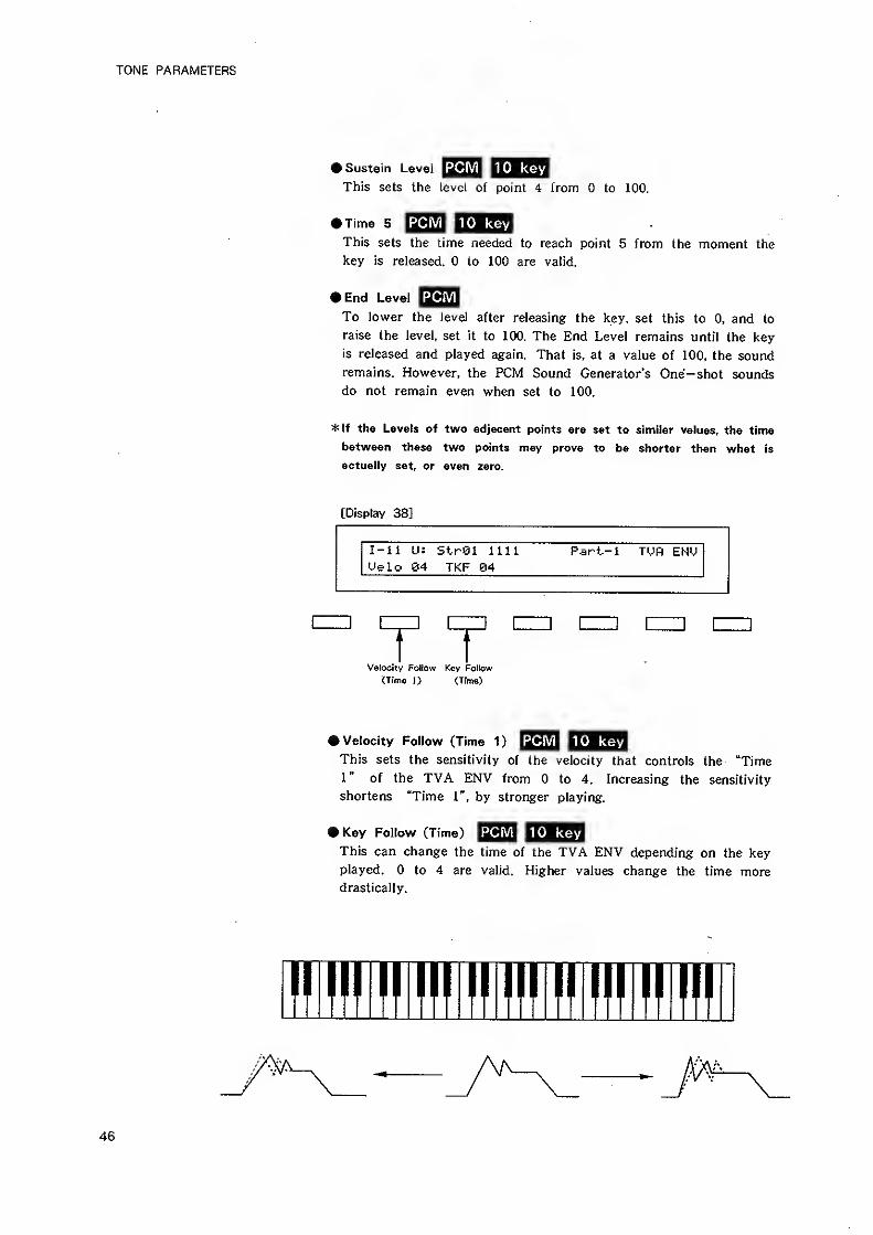
TONE PARAMETERS
PCMllO keyk Sustain Level
This sets the level of point 4 from to 100.
PCIVi|lO keyTime 5
This sets the time needed to reach point 5 from the moment the
key is released. to 100 are valid.
tEnd Level
To lower the level after releasing the key, set this to 0. and to
raise the level, set it to 100. The End Level remains until the key
is released and played again. That is, at a value of ICQ, the sound
remains. However, the PCM Sound Generator's One-shot sounds
do not remain even when set to 100.
*lf the Levels of two adjacent points are set to similar values, the time
betvtreen these two points may prove to be shorter than what is
actually set, or even zero.
[Display 38]
I-ll U: StrSl nil Part-i Ti.;R EHUUelo 84 TKF 84
Velocity Follow Key Follow
(Time 1) (Time)
PCMllO key• Velocity Follow (Time 1)
This sets the sensitivity of the velocity that controls the "Time1" of the TVA ENV from to 4. Increasing the sensitivity
shortens "Time 1", by stronger playing.
PCMllO key> Key Follow (Time)
This can change the time of the TVA ENV depending on the key
played. to 4 are valid. Higher values change the time moredrastically.
II III 1milmilmilnil
46
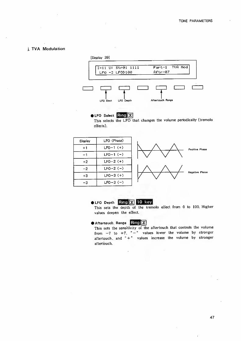
TONE PARAMETERS
j. TVA Modulation
[Display 39]
I-ll IJ: StrOl nilLFO -3 LFODiee
Part-1 TUfl Nod
fiftr-07
] [
LFO Sroct LFO D«oth Afiertouch Range
• LFO Select
This selects the LFO that changes the volume periodically (tremolo
effects).
Display LFO (Phase)
+ 1 LFO-1 (+)
-1 LFO-1 (-)
+2 LFO-2 (+)
-2 LFO-2 (-)
+3 LFO-3 (+)
-3 LFO-3 (-)
Positive Phase
Negative Phase
Ring H1 10 keyI LFO Depth ilfflglf^
This sets the depth of the tremolo effect from to 100. Higher
values deepen the effect.
Aftertouch Range
This sets the sensitivity of the aftertouch that controls the volume
from -7 to +7. " - " values lower the volume by stronger
aftertouch, and " + " values increase the volume by stronger
aftertouch.
47
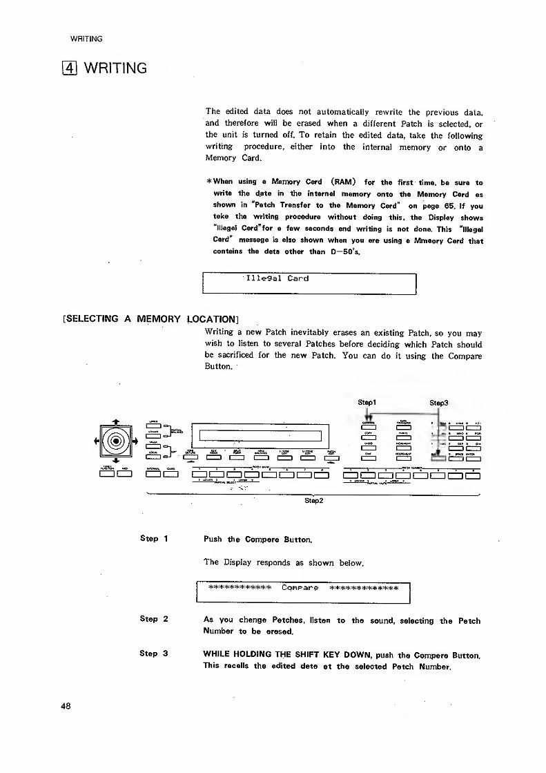
WRITING
m WRITING
The edited data does not automatically rewrite the previous data,
and therefore will be erased when a different Patch is selected, or
the unit is turned off. To retain the edited data, take the following
writing procedure, either into the internal memory or onto a
Memory Card.
*Wh8n using a Memory Card (RAM) for the first time, be sure to
write the diBta in the internal memory onto the Memory Card as
shown in "Patch Transfer to the Memory Card" on page 65. If you
take the writing procedure without doing this, the Display shows
"Illegal Card"for a few seconds and writing is not done. This "illegal
Card message is also shown when you are using a Mmeory Card that
contains the data other than D—50's.
Illegal Card
[SELECTING A MEMORY LOCATION]Writing a new Patch inevitably erases an existing Patch, so you maywish to listen to several Patches before deciding which Patch should
be sacrificed for the new Patch. You can do it using the CompareButton.
Step1 Steps
axic "iS?- -Hs-
n^ri>4 nft ntffttf* OiX» i i i 1 ---'^. f , , '
, J
—
• 5———— rvw^j-
—
, _^ I
aCZJ I=]l=] IZ=}IZ=IIIZ]CIZ]iZZICZICZ]CZI aiZ-ll—II—
I
I II II—
I
Step2
Step 1
Step 2
Step 3
Push the Compare Button.
The Display responds as shown below.
Compare
As you change Patches, listen to the sound, selecting the Patch
Number to be erased.
WHILE HOLDING THE SHIFT KEY DOWN, push the Compare Button.
This recalls the edited data at the selected Patch Number.
48
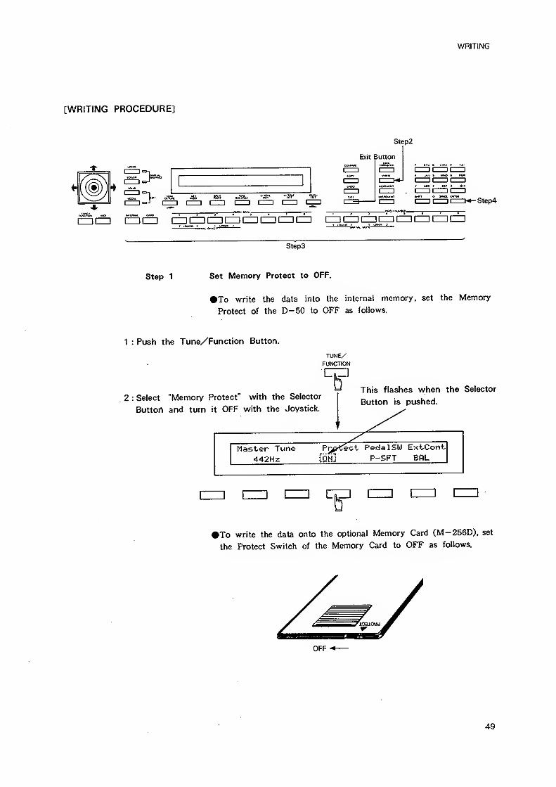
WRITING
[WRITING PROCEDURE]
Step2
Exit Button
I 1
I
cs-l
y •aa es 'va* "ns' tsr
cru 1=] nm czzi cm Step4
CZItZZ! IZZm CZ3CZIIZDCZDCDIIIDCI3CZ1 HZ] CZI iZD CZl CZICD
Step 1
Steps
Set Memory Protect to OFF,
To write the data into the internal memory, set the Memory
Protect of the D-50 to OFF as foliows.
1 : Push the Tune/Function Button.
TUNE/FUNCTION
2 : Select "Memory Protect" with the Selector
Button and turn it OFF with the Joystick.
This flashes when the Selector
Button is pushed.
Master Tune Pr^^H^eot- Pedal SW ExtCont
442Hz [QM] P-SFT BRL
>To write the data onto the optional Memory Card (M-256D), set
the Protect Switch of the Memory Card to OFF as follows.
OFF M—
49
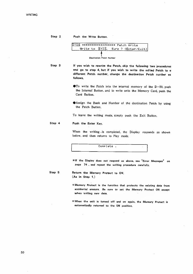
WRITING
Step 2 Push the Write Button.
ilrzAA; ****************** Patch Ur i t-e
Write to ff-llj. Sure ? f!Enter-^Exit>
Destination Patch Number
Step 3 tf you wish to rewrite the Patch, skip the following two procedures
and go to step 4. but if you wish to write the edited Patch to a
different Patch number, change the destination Patch number as
follows.
•To write the Patch into the internal memory of the D-50, push
the Internal Button, and to write onto the Memory Card, push the
Card Button.
•Assign the Bank and Number of the destination Patch by using
the Patch Button.
To leave the writing mode, simply push the Exit Button.
Push the Enter Key.
When the writing .is completed, the Display responds as shownbelow, and then returns lo Play mode.
Step 4
Complete .
*lf the Display does not respond as above, see "Error Messages" on
page 74 , and repeat the writing procedure carefully.
Step 5 Return the Memory Protect to ON.
(As in Step 1.)
* Memory Protect is the function that protects the existing data from
accidental erasure. Be sure to set the Memory Protect ON except
when writing new data.
*When the unit is turned off and on again, the Memory Protect is
automatically returned to the ON position.
50
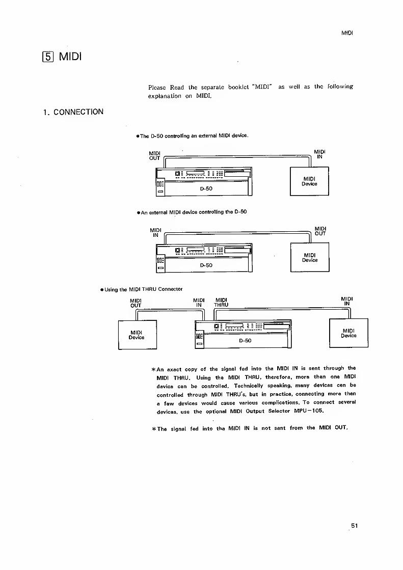
MIDI
MIDI
Please Read the separate booklet "MIDI" as well as the following
explanation on MIDI.
CONNECTION
I The D-50 controlling an external MID! device.
MIDIOUT
D-50
(An external MIDI dewce controlling the D-50
MIDIIN
D-50
MIDIOUT
• Using the MIDI THRU Connector
MID]OUT
MIDI MIDIIN THRU
D-50
MIDIIN
*An exact copy of the signal fed into the MIDI IN is sent through the
MIDI THRU. Using the MIDI THRU, therefore, more than one MIDI
device can be controlled. Technically speaking, many devices can be
controlled through MIDI THRU's, but in practice, connecting more than
a few devices v/ould cause various complications. To connect several
devices, use the optional MIDI Output Selector MPU — 105.
*The signal fed into the MIDI IN is not sent from the MIDI OUT.
51
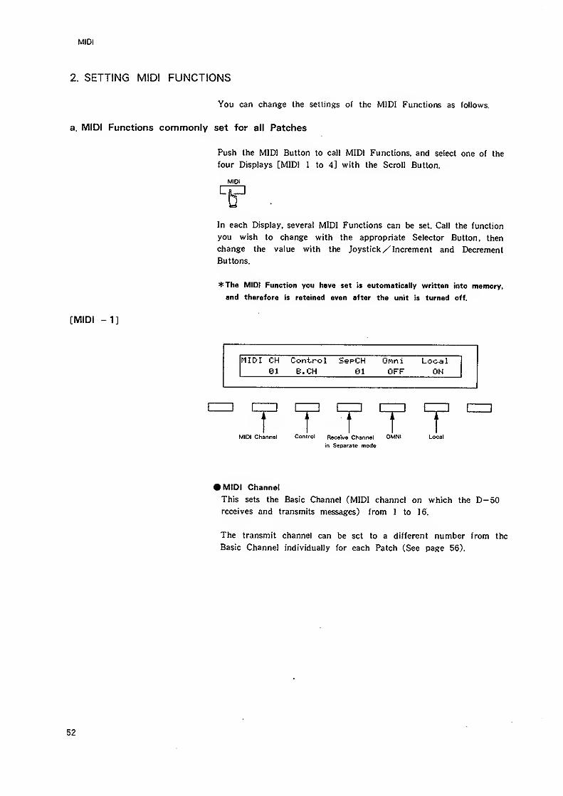
MIDI
2. SETTING MIDI FUNCTIONS
You can change the sellings of Ihe MIDI Functions as follows.
a. MIDI Functions commonly set for all Patches
Push the MIDI Button to call MIDI Functions, and select one of the
four Displays [MIDI 1 to 4] with the Scrol! Button.
MIDI
cm
In each Display, several MIDI Functions can be set. Call the function
you wish to change with the appropriate Selector Button, then
change the value with the Joystick/ Increment and Decrement
Buttons.
*Jhe MID) Function you have set is automatically written into memory,
and therefore is retained even after the unit is turned off.
[MIDI -1]
MIDI CH Control SepCH Local81 E.CH 01 OFF OH
f T T T 1lannel Conirol Receive Channel OMNI Loc:
in Separate mode
• MIDI Channel
This sets the Basic Channel (MIDI channel on which the D-50receives and transmits messages) from 1 to 16.
The transmit channel can be set to a different number from the
Basic Channel individually for each Patch (See page 56).
52
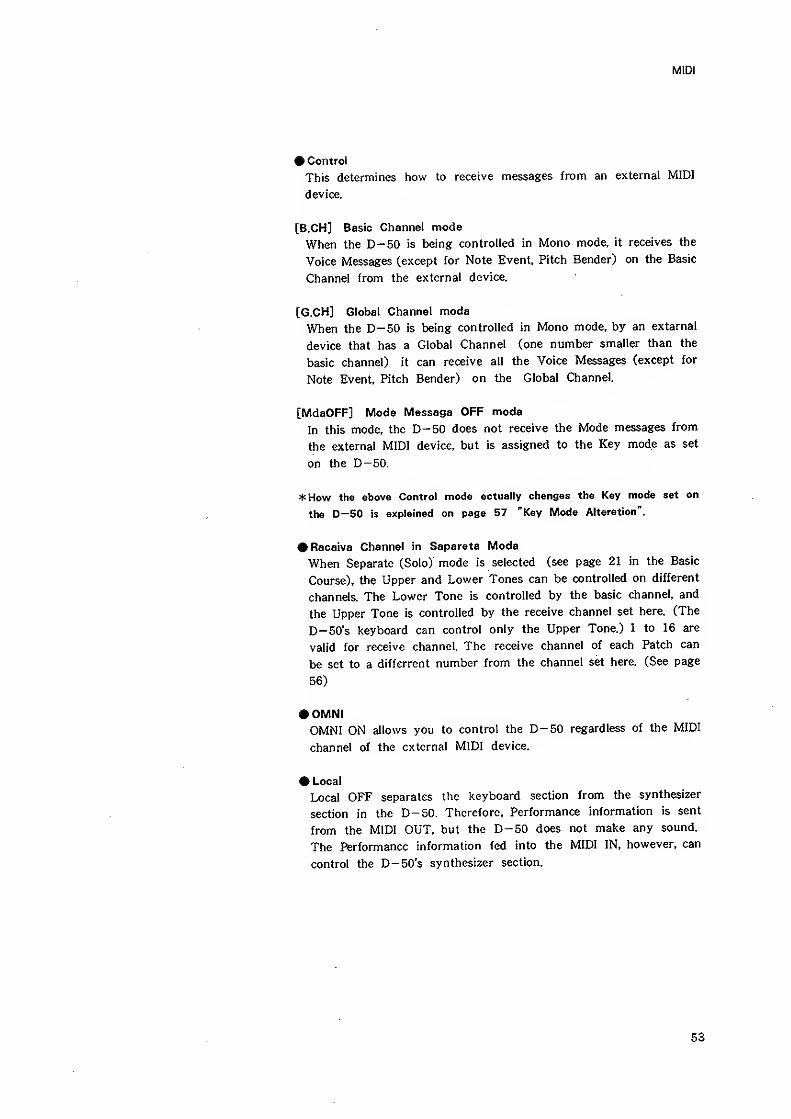
MIDI
• Control
This determines how to receive messages from an external MIDI
device.
[B.CH] Basic Channel mode
When the D-50 is being controlled in Mono mode, it receives the
Voice Messages (except for Note Event, Pitch Bender) on the Basic
Channel from the external device.
[G.CH] Global Channel mode
When the D-50 is being controlled in Mono mode, by an extarnal
device that has a Global Channel (one number smaller than the
basic channel) it can receive all the Voice Messages (except for
Note Event, Pitch Bender) on the Global Channel
[MdeOFF] Mode Message OFF mode
In this mode, the D-50 does not receive the Mode messages from
the external MIDI device, but is assigned to the Key mode as set
on the D-50.
*How the above Control mode actually changes the Key mode set on
the D-50 is explained on page 57 "Key Mode Alteration".
• Receive Channel in Separate Mode
When Separate (Solo) mode is selected (see page 21 in the Basic
Course), the Upper and Lower Tones can be controlled on different
channels. The Lower Tone is controlled by the basic channel, and
the Upper Tone is controlled by the receive channel set here. (The
D-50's keyboard can control only the Upper Tone.) 1 to 16 are
valid for receive channel. The receive channel of each Patch can
be set to a differrent number from the channel set here. (See page
56)
• OMNIOMNI ON allows you to control the D-50 regardless of the MIDI
channel of the external MIDI device.
• Local
Local OFF separates the keyboard section from the synthesizer
section in the D-50. Therefore, Performance information is sent
from the MIDI OUT, but the D-50 does not make any sound.
The Performance information fed into the MIDI IN, however, can
control the D-50's synthesizer section.
53
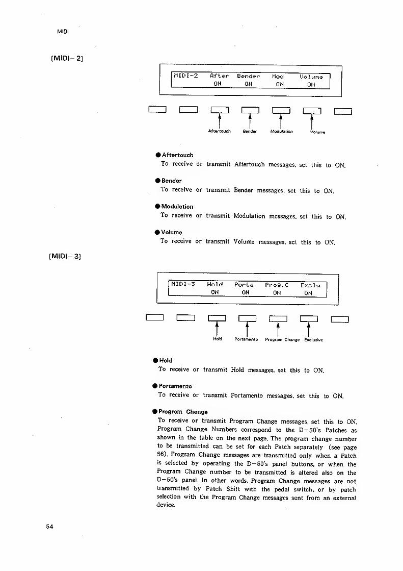
MIDI
[MIDI- 2]
MID I -2 After Bender Mod Uo 1 i-ifie
OH ON OH ON
] czi: 1—3 [
Aftertouch Bonder ModuPation Volume
# Aftertouch
To receive or transmit Aftertouch messages, sol this to ON.
Bender
To receive or transmit Bender messages, set this to ON.
# Modulation
To receive or transmit Modulation messages, sol this to ON.
# Volume
To receive or transmit Volume messages, set this to ON.
[MIDI- 3]
MIDI-3 Hold Porta Prog.
C
EKC 1 LJ
ON ON ON OH
EZZ] [
Hold Portamento Program Change Exclusive
»Hold
To receive or transmit Hold messages, set this to ON.
^ Portamento
To receive or transmit Portamento messages, set this to ON.
Program Change
To receive or transmit Program Change messages, set this to ON.Program Change Numbers correspond to the D-50's Patches as
shown in the table on the next page. The program change numberto be transmitted can be set for each Patch separately (see page56). Program Change messages are transmitted only when a Patchis selected by operating the D-50's panel buttons, or when the
Program Change number to be transmitted is altered also on the
D-50's panel. In other words. Program Change messages are not
transmitted by Patch Shift with the pedal switch, or by patch
selection with the Program Change messages sent from an external
device.
54
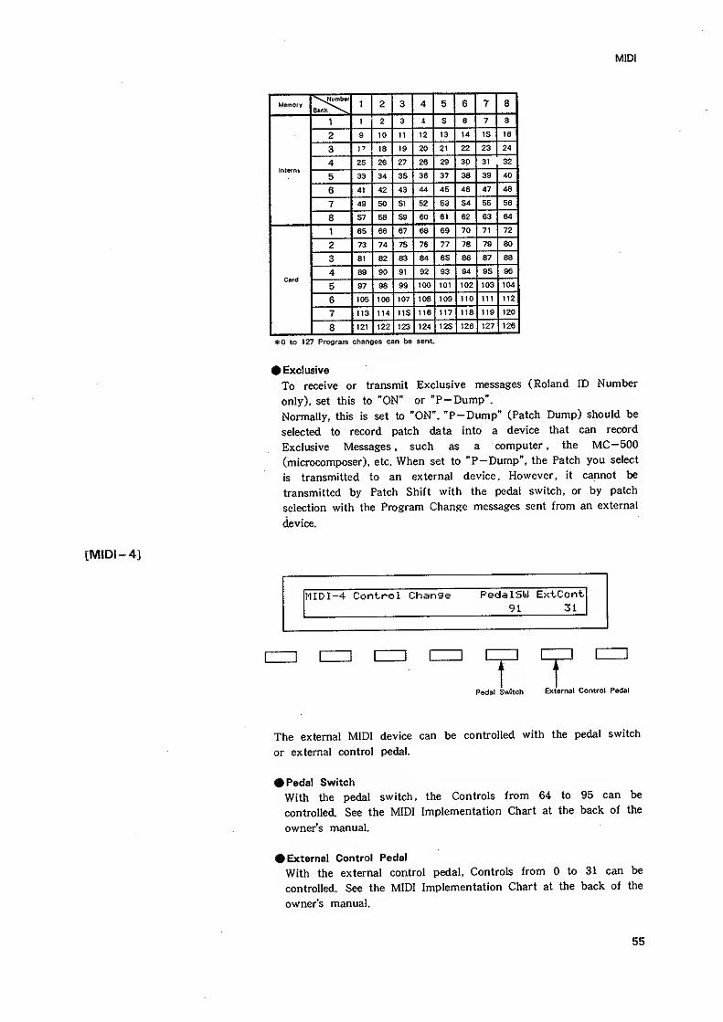
MIDI
Memory1 o
c.AH c D 71 oo
1 1 2 3 i 5 6 7 8
2 9 10 11 12 13 14 15 16
3 I"' 18 19 20 21 22 23 24
Intef
4 25 26 27 26 29 30 31 32
5 33 34 35 36 37 38 39 40
6 4t 42 43 44 45 46 47 48
7 49 50 51 52 53 54 55 56
8 57 58 59 60 61 62 63 64
1 65 66 67 68 69 70 71 72
2 73 74 75 76 77 78 79 80
3 81 82 83 84 85 86 87 88
Card4 89 90 91 92 93 94 95 96
5 97 98 S9 100 101 102 103 104
6 105 106 107 108 109 no 111 112
7 113 114 115 116 117 118 119 120
8 121 122 123 124 125 126 127 128
*0 to 127 Program changes can be sent.
# Exclusive
To receive or transmit Exclusive messages (Roland ID Number
only), set this to "ON" or "P-Dump".
Normally, this is set to "ON". "P-Dump" (Patch Dump) should be
selected to record patch data into a device that can record
Exclusive Messages , such as a computer , the MC-500
(microcomposer), etc. When set to "P-Dump", the Patch you select
is transmitted to an external device. However, it cannot be
transmitted by Patch Shift with the pedal switch, or by patch
selection with the Program Change messages sent from an external
device.
[MIDI -4]
t'IIDI-4 Control Change PedalSU Ext-Cont
91 31
Pedal Switch External Control Pedal
The external MIDI device can be controlled with the pedal switch
or external control pedal.
• Pedal Switch
With the pedal switch, the Controls from 64 to 95 can be
controlled. See the MIDI Implementation Chart at the back of the
owner's manual.
• External Control Pedal
With the external control pedal. Controls from to 31 can be
controlled. See the MIDI Implementation Chart at the back of the
owner's manual.
55
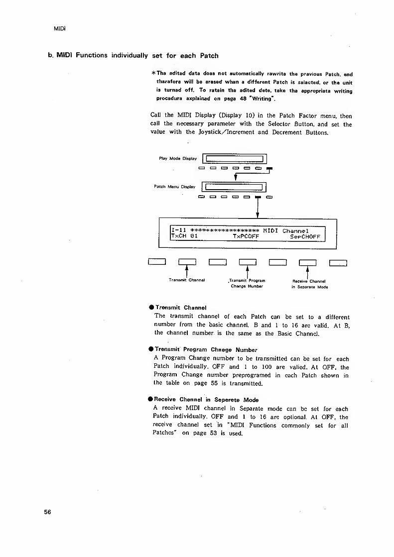
MIDI
b. MIDI Functions individually set for each Patch
*The edited data does not automatically rewrite the previous Patch, and
therefore will be erased when a different Patch is selected, or the unit
is turned off. To retain the edited data, take the appropriate writing
procedure explained on page 48 "Writing".
Call the MIDI Display (Display 10) in the Patch Factor menu, then
call the necessary parameter with the Selector Button, and set the
value with the Joystick/Increment and Decrement Buttons.
Play Moda Olsclay[ |
cn nn czn c=3 cn CD
f
'
Patch Menu Display(
|
c=: en C3 c=i czi M
I-ll MIDI ChannelTxCH 01 TxPCOFF SepCHOFF
Transmit Channel _Transmit Program
Change NumberReceive Channel
in Separate Mode
• Transmit Channel
The transmit channel of each Patch can be set to a different
number from the basic channel. B and 1 to 16 are valid. At B,
the channel number is the same as the Basic Channel.
• Transmit Program Chnage NumberA Program Change number to be transmitted can be set for eachPatch individually. OFF and 1 to 100 are valied. At OFF, the
Program Change number preprogramed in each Patch shown in
the table on page 55 is transmitted.
• Receive Channel in Separate ModeA receive MIDI channel in Separate mode can be set for each
Patch individually. OFF and 1 to 16 are optional. At OFF, the
receive channel set in "MIDI Functions commonly set for al!
Patches" on page 53 is used.
56
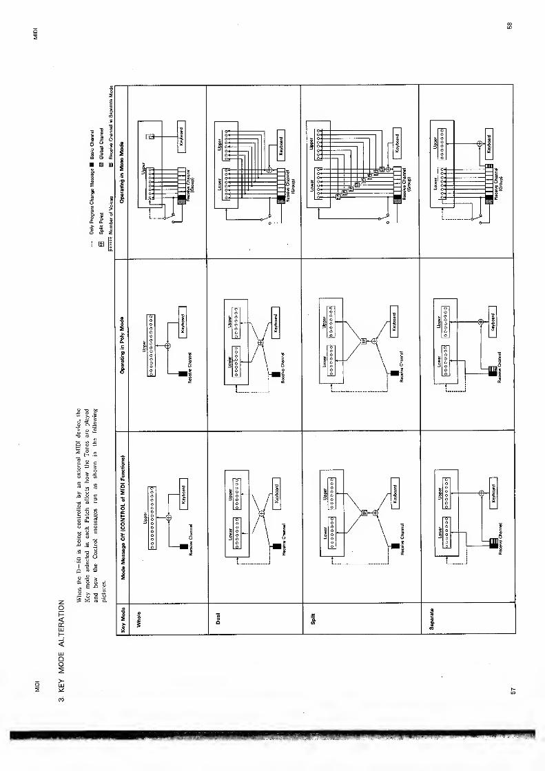
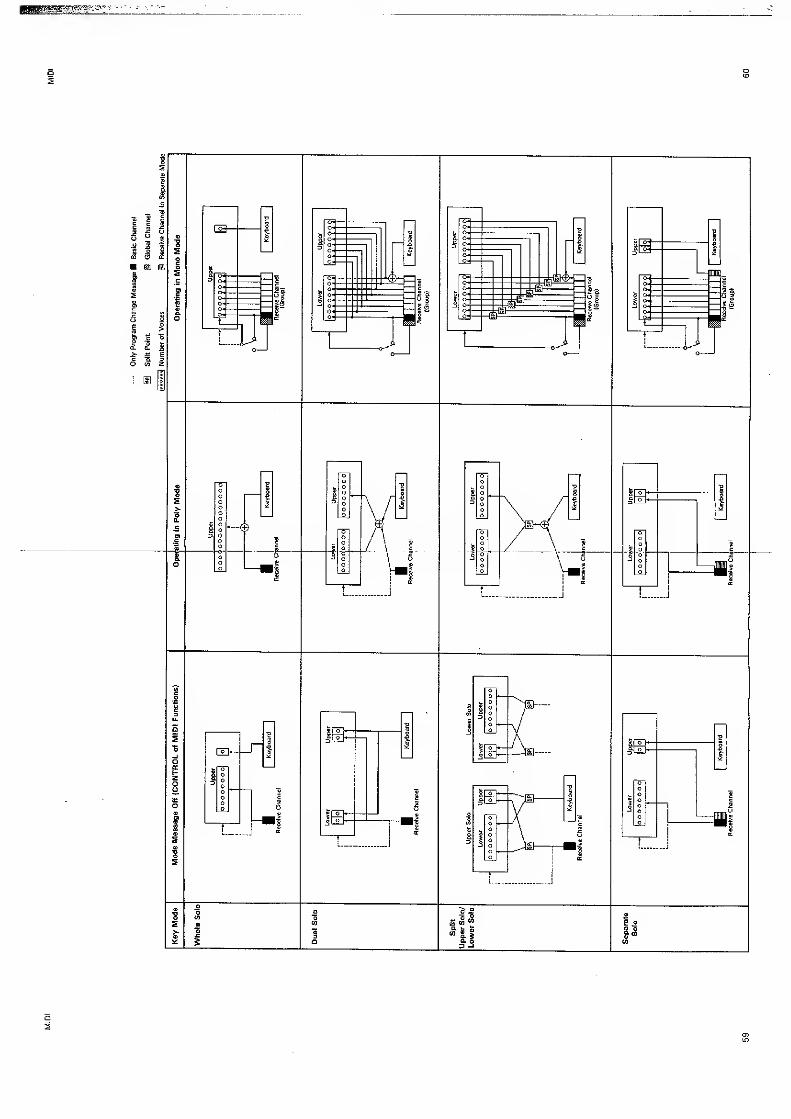
oID
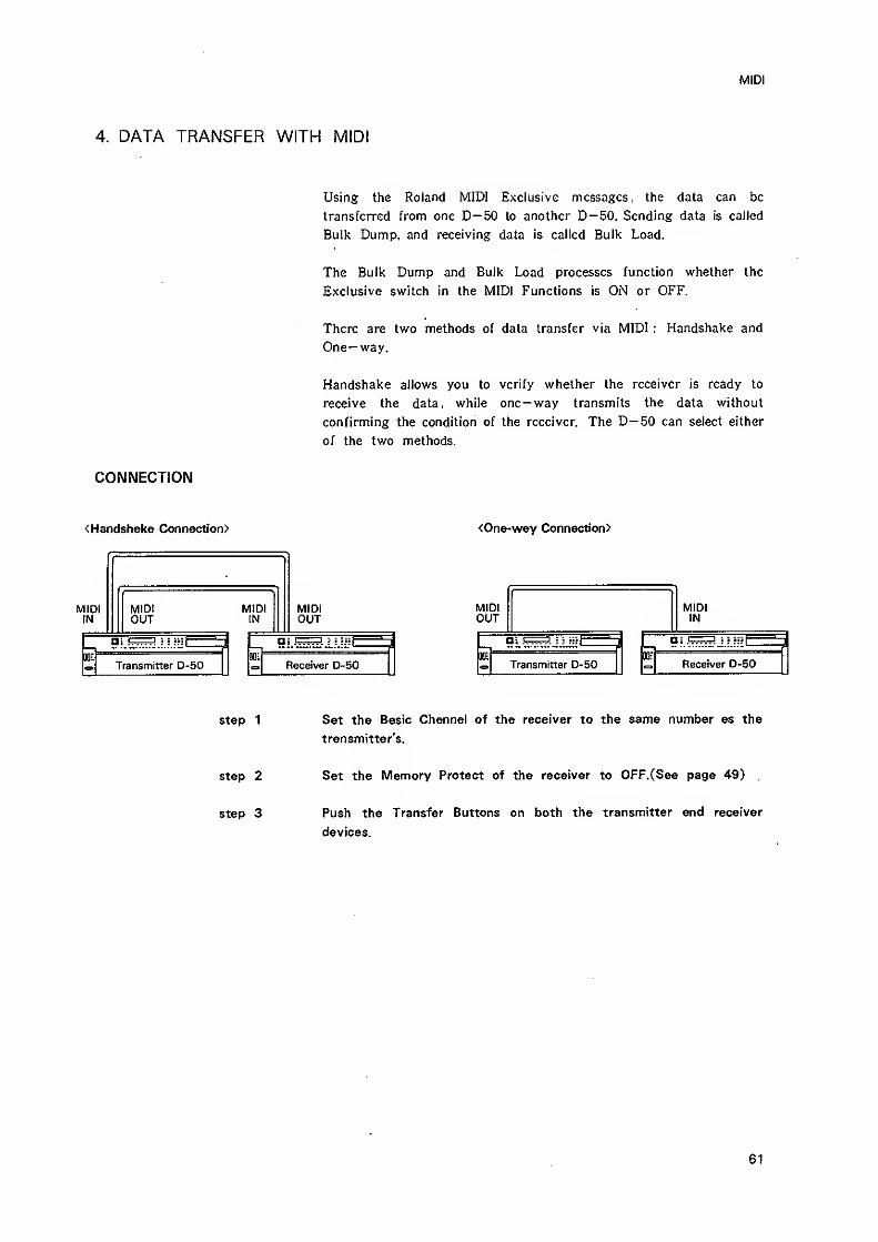
MIDI
4. DATA TRANSFER WITH MIDI
Using the Roland MIDI Exclusive messages, the data can be
transferred from one D-50 to another D-50. Sending data is called
Bulk Dump, and receiving data is called Bulk Load.
The Bulk Dump and Bulk Load processes function whether the
Exclusive switch in the MIDI Functions is ON or OFF.
There are two methods of data transfer via MIDI ; Handshake and
One— way.
Handshake allows you to verify whether the receiver is ready to
receive the data , while one— way transmits the data without
confirming the condition of the receiver. The D-50 can select either
of the two methods.
CONNECTION
<Handshake Connection> <One-way Connection)
MIDIIN
MIDtOUT
MIDIIN
i
Transmitter D-50
MIDIOUT
i
Receiver D~50
MIDIOUT
MIDIIN
i J 1 III1 '
i
Transmitter D-50JU:
Receiver D-50
step 1 Set the Basic Channel of the receiver to the same number as the
transmitter's.
step 2 Set the Memory Protect of the receiver to OFF,(See page 49).
step 3 Push the Transfer Buttons on both the transmitter and receiver
devices.
61
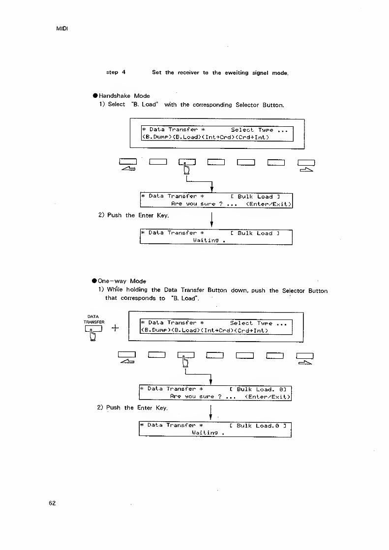
step 4 Set the receiver to the awaiting signal mode.
• Handshake Mode
1) Select "B. Load" with the corresponding Selector Button.
* Data Transfer * Select Type ...
<B. DunpXE.LoadX Int->Crd> tCrd->Int>
nzD nzj nzn
* Data Jr^nsrfer * I Bulk Load ]
fire you sure ? <Enter^Exit>
inter Key.
|
* Data Trsns-f'er * L Bulk Load 2
Waiting .
>One-way Mode
1) While holding the Data Transfer Button down, push the Selector Button
that corresponds to "B. Load".
DATATRANSFER * Data Transfer * Select Type
<B.Durip><e.Load>< Int-*Crd><Crd^Int>
nz2 c
* Data Transfer * C Bulk Load. 83fire you sure ? ... <Enter^EKit>
2) Push the Enter Key.
* Data Transfer * C Bulk Load.e 3
Waiting .
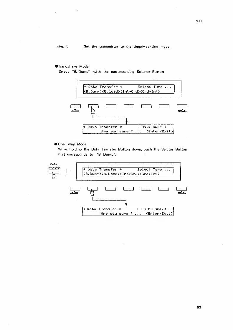
step 5 Set the transmitter to the signal— sending mode.
• Handshake Mode
Select "B. Dump" with the corresponding Selector Button.
* Data Trart&f'er * Select Type ...
<B.Dunp><B.Load>ant-fCrd>(:Crd^Int>
1
1 i t I 1 lilt
i+ Data Transfer * C Bulk DufOF D
fire you sure ? <:Enter/^Exit>
• One-way Mode
While holding the Data Transfer Button down, push the Selctor Button
that corresponds to "B. Dump".
DATATRANSFER
c—i + * Data Transfer * Select TypeCB. Dunp> <B. Load> < Int^Crd> <Crd^Int>
I I C
* Data Transfer *
flre you sure ?
C Bulk DuMP.0 D
<;Enter-^Exit>
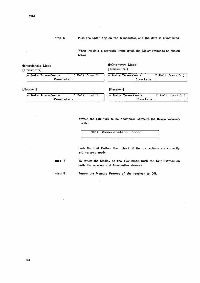
MIDI
step 6 Push the Enter Key on the transmitter, and the data is transferred.
When the data is correctly transferred, the Diplay responds as shown
below.
• Handshake Mode •One-way Mode
[Transmitter] [Transnfiitter]
* Daia Transfer * t Bulk Dunp ]
Conplete .
* Data Transfer * 1 Bulk Dunp.O ]
Complete .
[Receiver] [Receiver]
* Data Transfer * L Bulk Load 1
CoNPlet-e .
* Data Transfer * L Bulk Load.O 1
Conplete .
*When the data fails to be transferred correctly, the Display responds
with :
MIDI Connunication Error
Push the Exit Button, then check if the connections are correctly
and securely made.
step 7 To return the Display to the play mode, push the Exit Buttons on
both the receiver and transmitter devices.
step 8 Return the Memory Protect of the receiver to ON.
64
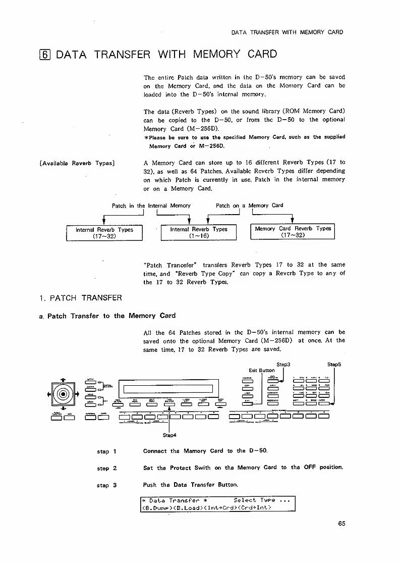
DATA TRANSFER WITH MEMORY CARD
\E DATA TRANSFER WITH MEMORY CARD
The entire Palch data written in the D-50's memory can be saved
on the Memory Card, and the data on the Memory Card can be
loaded into the D-50's internal memory.
The data (Reverb Types) on the sound library (ROM Memory Card)
can be copied to the D-50, or from the D-50 to the optional
Memory Card (M-256D).
* Please be sure to use the specified Memory Card, such as the supplied
Memory Card or M-256D.
[Available Reverb Types] A Memory Card can store up to 16 different Reverb Types (17 to
32), as well as 64 Patches. Available Reverb Types differ depending
on which Patch is currently in use, Patch in the internal memory
or on a Memory Card.
Patch in the Internal Memor/ Patch on a Memory Card
1 finternal Reverb Types
(17-32)Internal Reverb Types
(1-16)
Memory Card Reverb Types(17-32)
"Patch Trancefer" transfers Reverb Types 17 to 32 at the same
time, and "Reverb Type Copy" can copy a Reverb Type to any of
the 17 to 32 Reverb Types.
1. PATCH TRANSFER
a. Patch Transfer to the Memory Card
step 1
step 2
step 3
All the 64 Patches stored in the D-50's internal memory can be
saved onto the optional Memory Card (M-256D) at once. At the
same time, 17 to 32 Reverb Types are saved.
StepsExit Button I
Steps
I I I I I 1
CD czi CD cn CZI
Step4
Connect the Memory Card to the D — 50.
Set the Protect Swith on the Memory Card to the OFF position.
Push the Data Transfer Button.
* Data Transfer * Select Type . .
.
CB. DuroPXE. LoadX Int-^Crd> <Crd-Mnt>
65
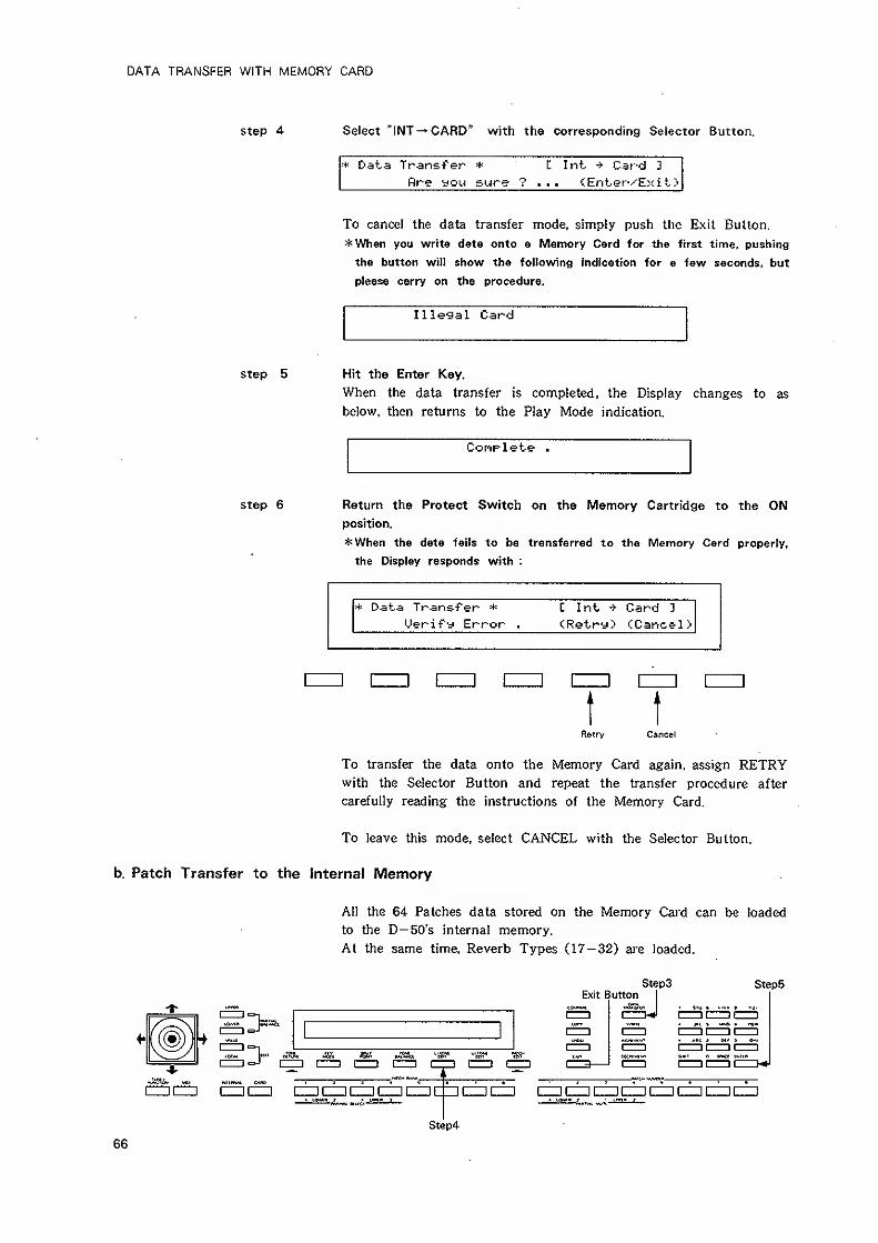
DATA TRANSFER WITH MEMORY CARD
step 4 Select "INT^CARD" with the corresponding Selector Button.
+ Data Transfer * L Int. Card 3
flre you sure ? tEnter'^Exit->
To cancel Ihe data transfer mode, simply push the Exit Button.
*When you write data onto a Memory Card for the first time, pushing
the button will show the following indication for a few seconds, but
please carry on the procedure.
Illegal Card
step 5 Hit the Enter Key.
When the data transfer is completed, the Display changes to as
below, then returns to the Play Mode indication.
Complete .
step 6 Return the Protect Switch on the Memory Cartridge to the ONposition.
*When the data fails to be transferred to the Memory Card properly,
the Display responds with :
+ Data Transfer * C Int ^ Card D
Uerify Error . tRetry> CCancel
>
[= an izz] czzi [= nm \—j
t tRetry Cancel
To transfer the data onto the Memory Card again, assign RETRYwith the Selector Button and repeat the transfer procedure after
carefully reading the instructions of the Memory Card.
To leave this mode, select CANCEL with the Selector Button.
b. Patch Transfer to the Internal Memory
All the 64 Patches data stored on the Memory Card can be loaded
to the D— 50's internal memory.
At the same time. Reverb Types (17-32) are loaded.
Steps Step5
Step4
66
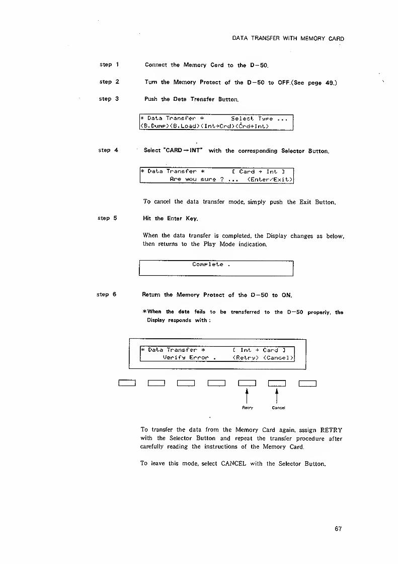
DATA TRANSFER WITH MEMORY CARD
step 1 Connect the Memory Card to the D-50.
step 2 Turn the Memory Protect of the D-50 to OFF. (See page 49.)
step 3 Push the Data Transfer Button.
* Data Transfer Select Type . . .
<E. DunpXB. Load> <. Int->Crd> <Crd->Int>
step 4 Select "CARD^ INT" with the corresponding Selector Button.
* Data Transfer * C Card ^ Int ]
fire you sure ? ... <Enter'^E?<it>
To cancel the data transfer mode, simply push the Exit Button,
step 5 Hit the Enter Key.
When the data transfer is completed, the Display changes as below,
then returns to the Play Mode indication.
Complete .
step 6 Return the Memory Protect of the D-50 to ON.
*When the data fails to be transferred to the D—50 properly, the
Display responds with :
* Data Transfer *
Uerify Error .
C Int Card 3
<Retry> <Cancel
>
EZZl [
Retry Cancel
To transfer the data from the Memory Card again, assign RETRYwith the Selector Button and repeat the transfer procedure after
carefully reading the instructions of the Memory Card.
To leave this mode, select CANCEL with the Selector Button.
67
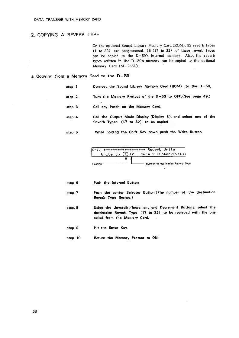
DATA TRANSFER WITH MEMORY CARD
2. COPYING A REVERB TYPE
On the optional Sound Library Memory Card (ROM), 32 reverb types
(1 to 32) are programmed. 16 (17 to 32) of these reverb types
can be copied to the D— 50's internal memory. Also, the reverb
types written in the D— 50's memory can be copied to the optional
Memory Card (M-256D).
a. Copying from a Memory Card to the D- 50
step 1 Connect the Sound Library Memory Card (ROM) to the D-50.
Turn the Memory Protect of the D-50 to OFF.(See page 49.)
Call any Patch on the Memory Card.
step 2
step 3
step 4
step 5
Call the Output Mode Display (Display 8), and select one of the
Reverb Types (17 to 32) to be copied.
While holding the Shift Key down, push the Write Button.
C-i 1 ****************** Reyerb Ulrite
Write to Tlf-l?. Sure ? <Enter-^Exit.>
Flashing Number of destination Reverb Type
Step 6 Push the Internal Button.
step 7 Push the center Selector Button. (The number of the destination
Reverb Type flashes.)
step- 8 Using the Joystcik/lncrement and Decrement Buttons, select the
destination Reverb Type (17 to 32) to be replaced with the one
called from the Memory Card.
step 9 Hit the Enter Key.
step 10 Return the Memory Protect to ON.
68
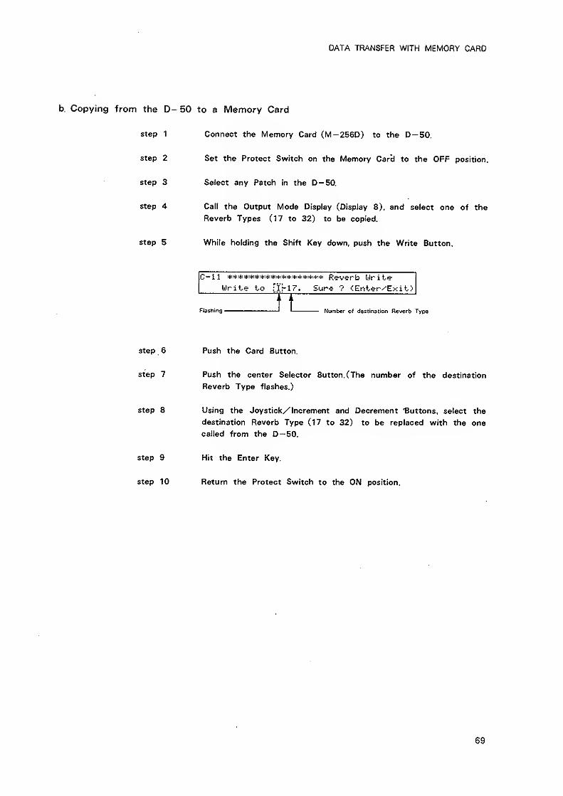
DATA TRANSFER WITH MEMORY CARD
b. Copying from the D- 50 to a Memory Card
step 1 Connect the Memory Card (M-256D) to the D-50.
step 2 Set the Protect Switch on the Memory CarcJ to the OFF position.
step 3 Sefect any Patch in the D-50.
step 4 Call the Output Mode Display (Display 8), and select one of the
Reverb Types (17 to 32) to be copied.
step 5 While holding the Shift Key down, push the Write Button.
Write to :l\-17. Sure ? <Enter^Exit>
Rashing ^ Number of destination Reverb
Step 6 Push the Card Button.
step 7 Push the center Selector Button. (The number of the destination
Reverb Type flashes.)
step 8 Using the Joystick/Increment and Decrement buttons, select the
destination Reverb Type (17 to 32) to be replaced with the one
called from the D— 50.
step 9 Hit the Enter Key.
step 10 Return the Protect Switch to the ON position.
69
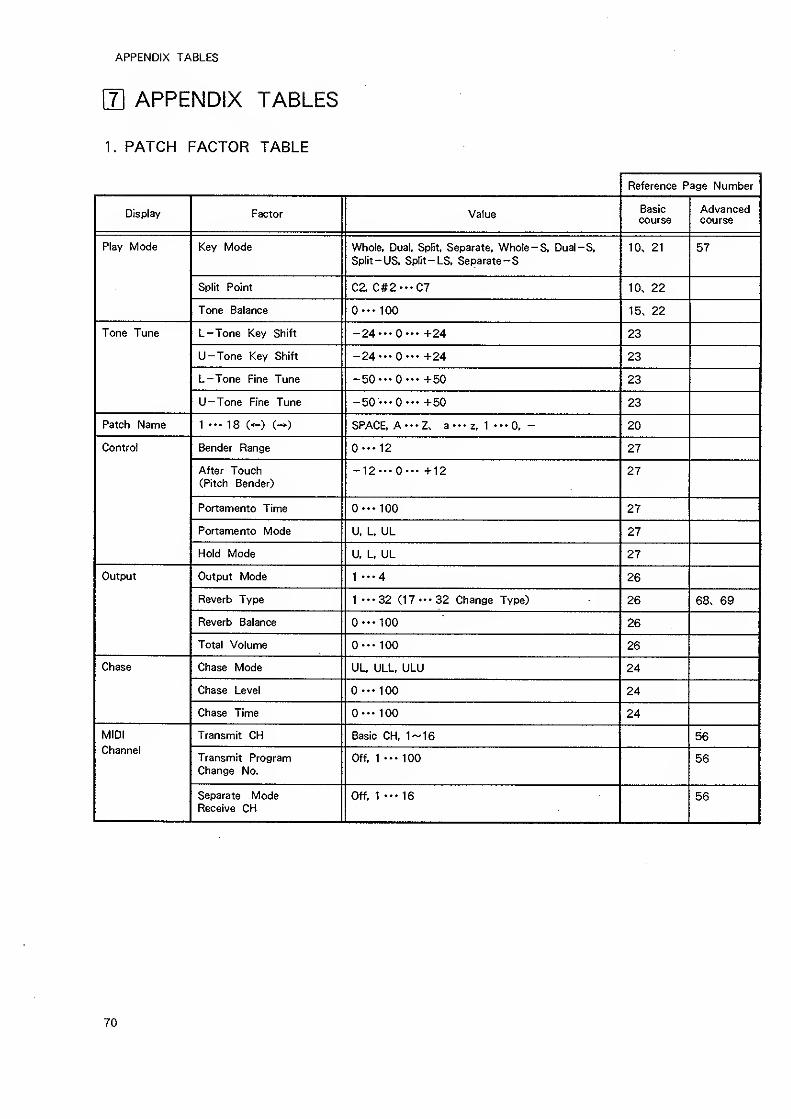
APPENDIX TABLES
J\ APPENDIX TABLES
1 . PATCH FACTOR TABLE
Reference Page Number
Display Factor Value Basiccourse
Advancedcourse
Play Mode Key Mode Whole, Dual, Split. Separate. Whole -S, Dual-S,
Solit— US Solit— LS Seoarate— S10, 21 57
Split Point C2, C#2---C7 10. 22
Tone Balance O"- 100 15. 22
Tone Tune L-Tone Key Shift -24 •••O— +24 23
U-Tone Key Shift -24 '"O"' +24 23
L-Tone Fine Tune -50'"0". +50 23
U-Tone Fine Tune -50 •"O". +50 23
Patch Name 1 ."18 C^) C-*) SPACE. A--Z. a-"z, 1 .-O, - 20
Control Bender Range 0'" 12 27
After Touch(.ritch Benderj
-12--0— +12 27
Portamento Time 0"' 100 27
Portamento Mode U. L, UL 27
Hold Mode U, L. UL 27
Output Output Mode 1 •••4 26
Reverb Type 1 •••32 (17 •••32 Change Type) 26 68. 69
Reverb Balance 0---100 26
Total Volume O^^^ 100 26
Chase Chase Mode UL, ULL, ULU 24
Chase Level 0--' 100 24
Chase Time O^^^ 100 24
MIDI Transmit CH Basic CH, 1-16 56Channel
Transmit ProgramChange No.
Off, 1 '•• 100 56
Separate ModeReceive CH
Off, 1"* 16 56
70
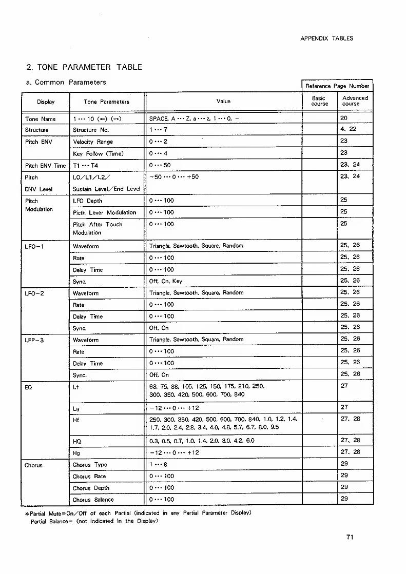
APPENDIX TABLES
2. TONE PARAMETER TABLE
a. Common ParametersReference Page Number
Display Tone Parameters V Cl^UCBasiccourse
Advancedcourse
Tone Name 1 10 C-) (-*) SPACE. A"*Z. a-'Z. 1 •-•0. - 20
Structure Structure No. 1 •••7 4, 22
Pitch ENV Velocity Range — 2 23
Key Follow (Time) 0--4 23
Pitch ENV Time T1 •••T4 0--50 23. 24
Pitch
ENV Level
L0/L1/L2/
Sustain Level/End Level
-50 •"0-" +50 23. 24
Pitch
Modulation
LFO Depth 0"- 100 25
Picth Lever Modulation O--- 100 25
Pitch After Touch
Modulation
100 25
LFO-1 Waveform Triangle, Sawtooth, Square, Random 25. 26
Rate 0--100 25. 26
Delay Time 100 25. 26
Sync. Off, On. Key 25. 26
LFO-2 Waveform Triangle, Sawtooth, Square. Random 25. 26
Rate 0"- 100 25. 26
Delay Time 0-" 100 25. 26
Sync. Off, On 25. 26
LFP-3 Waveform Triangle, Sawtooth, Square, Random 25. 26
Rate 0-" 100 25. 26
Delay Time O"- 100 25. 26
Sync. Off. On 25. 26
EQ Lf 63. 75. 88. 105. 125. 150. 175, 210. 250.
300. 350. 420. 500. 600. 700, 840
27
Lg -12"-0"- +12 27
Hf 250. 300, 350. 420, 500, 600. 700. 840, 1.0. 1.2. 1.4,
1.7, 2.0. 2.4. 2.8. 3.4. 4.0, 4.8. 5.7, 6.7. 8.0. 9.5
27. 28
HQ 0.3, 0.5. 0.7. 1 .0, 1 .4, 2.0. 3.0. 4.2. 6.0 27. 28
Hg -12*"0-" +12 27. 28
Chorus Chorus Type 1 "-S 29
Chorus Rate O"- 100 29
Chorus Depth 0-" ICQ 29
Chorus Balance 0— 100 29
Partial Mute=0n/0ff of each Partial (indicated in any Partial Parameter Display)
Partial Balance= (not indicated in the Display)
71
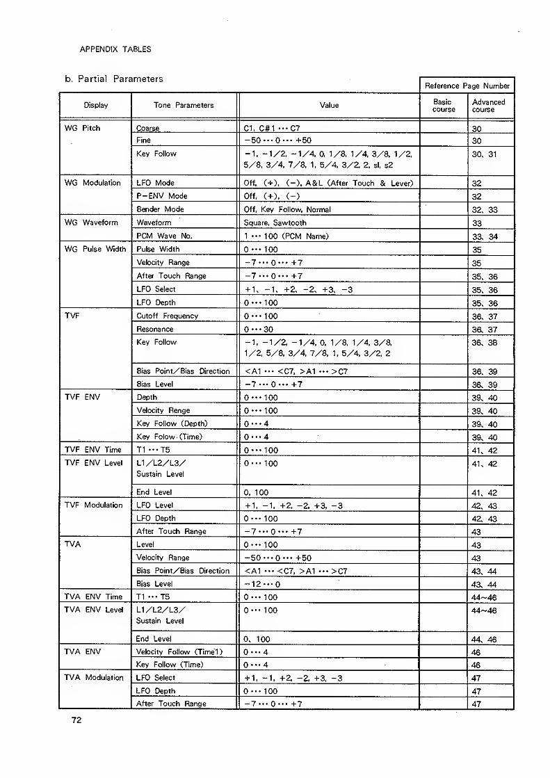
APPENDIX TABLES
b. Partial ParametersReference Page Number
Display Tone Parameters ValueBasiccourse
Advancedcourse
WG Pitch Coarse 01. C#l •••07 30
Fine -50 •••O^-- +50 30
Key Followf -1, -1/2, -1/4. 0, 1/8. 1/4, 3/8, 1/2,
5/8, 3/4, 7/8, 1. 5/4. 3/2. 2. si, s2
30. 31
WG Modulation LFO Mode Off. <+), (-), A&L (After Touch & Lever) 32
P-ENV Mode Off, (+). (-) 32
Bender Mode Off, Key Follow, Normal 32. 33
WG Waveform Waveform Square, Sawtooth 33
PCM Wave No. 1 *" 100 (PCM Name) 33. 34
WG Pulse Width Pulse Width O"- 100 35
Velocity Range -7--0"' +7 35
After Touch Range -7--0"- +7 35. 36
LFO Select + 1. +2. -2. +3. -3 35. 36
LFO Depth 0-" 100 35. 36
TVF Cutoff Frequency 0--100 36. 37
Resonance 0--30 36. 37
Key Follov\^ -1, -1/2. -1/4. 0, 1/8. 1/4, 3/8.
1/2, 5/8, 3/4, 7/8. 1, 5/4. 3/2. 2
36. 38
Bias Point/Bias Direction <A1 ••• <C7. >A1 >C7 36. 39
Bias Level _7...0... +7 36. 39
TVF ENV Depth 0"- 100 39. 40
Velocity Renge 0-" 100 39. 40
Key Follow (Depth) 0--4 39. 40
Key Folow (Time) O...4 39. 40
TVF ENV Time T1 "-T5 0'" 100 41. 42
TVF ENV Level L1/L2/L3/Sustain Level
©••- 100 41. 42
End Level 0, 100 41. 42
TVF Modulation LFO Level + 1. -1, +2, -2. +3. -3 42. 43
LFO Depth O-^- 100 42. 43
After Touch Range -7--0"- +7 43
TVA Level O"^ 100 43
Velocity Range -50^-*0"- +50 43
Bias Point/Bias Direction <A1 ••• <C7. >A1 >C7 43. 44
Bias Level -12... 43. 44
TVA ENV Time T1 -"TS O"* 100 44-46
TVA ENV Level L1/L2/L3/Sustain Level
0-" 100 44-46
End Level 0. 100 44. 46
TVA ENV Velocity Follov^' (Timel) '"4 46
Key Follow (Time) ©•••4 46
TVA Modulation LFO Select + 1, -1, +2. -2. +3, -3 47
LFO Depth O^" 100 47
After Touch Range _7...0^^.+7 47
72
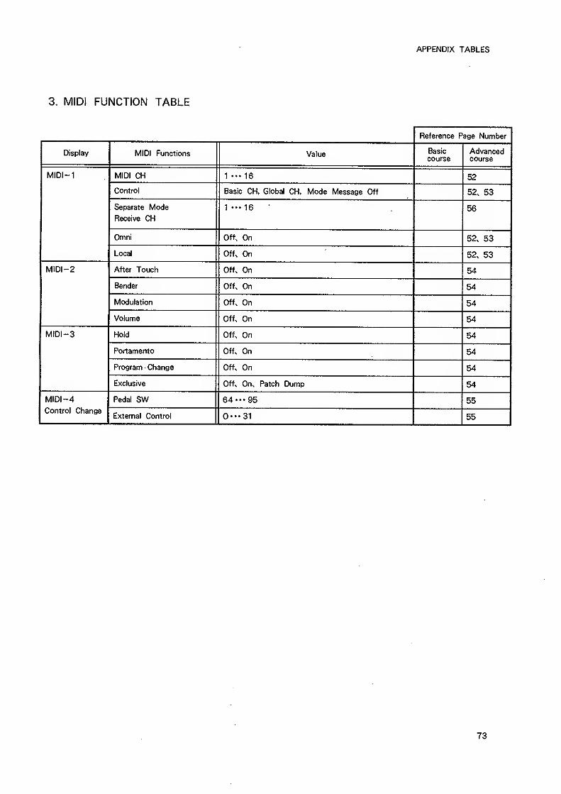
APPENDIX TABLES
3. MIDI FUNCTION TABLE
Reference Page Number
Display MIDI Functions Valuecourse course
MIDI-1 MIDI CH 1 16 52
Control Basic CH, Global CH. Mode Message Off 52, 53
Separate Mode
Receive CH
1---16 56
Omni Off. On 52. 53
Local Off. On 52, 53
MlDI-2 After Touch Off. On 54
Bender Off. On 54
Modulation Off. On 54
Volume Off. On 54
MIDI-3 Hold Off. On 54
Portamento Off. On 54
Program - Change Off. On 54
Exclusive Off. On. Patch Dump 54
MIDI -4Control Changs
Pedal SW 55
External Control 0--31 55
73
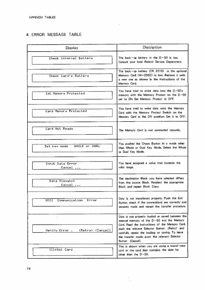
APPENDIX TABLES
4. ERROR MESSAGE TABLE
Display Discription
The back-up battery in the D-50 is low.
Consult your local Roland Service Department
Check Internal Battery
The back-up battery (CR 2016) in the optional
Memory Card CM -2560) is low. Replace it with
a new one as shown in the instructions of the
Memory Card.
Check Card's Battery
You have tried to write data into the D-50's
momnrv/ with th^ KApmr^rv/ PmtPf^t r»n thp O— ^0
set to ON. Set Memory Protect to OFF.
Int Mefiory Protected
You have tried to write data onto the Memory
(.jSru Wlin xne ivieinory rrotetit owiiun on irie
Memory Card in the ON position. Set it to OFF.
Card Merfiory Protected
The Memory Card is not connected securely.Card Not Ready
You pushed the Chase Sutton in a mode other
than Whole or Dual isey Moae. oeiect tne wnoie
or Dual Key Mode.
Set key node WHOLE or DUfiL
You have assigned a value that exceeds the
valid range.
Input Data ErrorCancel . .
.
The destination Block you have selected differs
from the source Block. Reselect the appropriate
Block, and repeat Block Copy.
Data Nisfiatch
Cancel . .
.
Data is not transferred property. Push the Exit
Button, check if the connections are correctly and
securely made and repeat the transfer procedure.
MIDI Cof'if'iun i cat i on Error
Data is not properly loaded or saved between the
internal memory of the D-50 and the Memory
Card. Read the instructions of the Memory Card,
push the relevant Selector Button (Retry) and
carefully repeat the loading or saving. To leave
the transfer mode, push the relevant Selector
Button (Cancel).
Uerify Error . <Retry> <;Cancel>
This is shown when you are using a brand-new
card or the card that contains the data for
other than the D-50.
Illegal Card
74
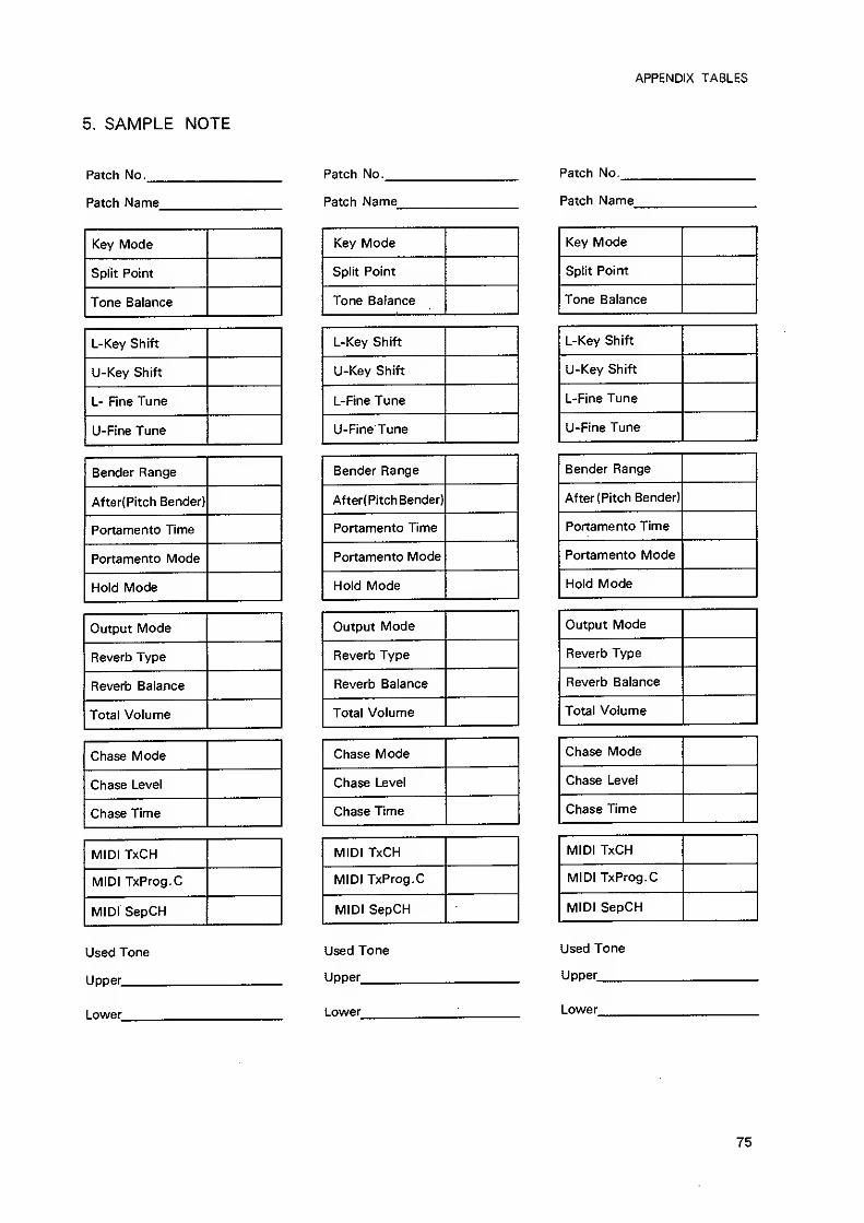
5. SAMPLE NOTE
Patch No.
Patch Name
Key Mode
Split Point
Tone Balance
L-Key Shift
U-Key Shift
L- Fine Tune
U-Fine Tune
Bender Range
After{Pitch Bender)
Portamento Time
Portamento Mode
Hold Mode
Output Mode
Reverb Type
Reverb Balance
Total Volume
Chase Mode
Chase Level
Chase Time
MIDI TxCH
MIDI TxProg.C
MIDI SepCH
Used Tone
Upper
Lower
Patch No.
Patch Name
Key Mode
Split Point
Tone Balance
L-Key Shift
U-Key Shift
L-Fine Tune
U-Fine Tune
Bender Range
After(PitchBender)
Portamento Time
Portamento Mode
Hold Mode
Output Mode
Reverb Type
Reverb Balance
Total Volume
Chase Mode
Chase Level
Chase Time
MIDI TxCH
MIDI TxProg.C
MIDI SepCH
Used Tone
Uooer
Lowfer
APPENDIX TABLES
Patch No.
Patch Name
Key Mode
Split Point
Tone Balance
L-Key Shift
U-Key Shift
L-Fine Tune
U-Fine Tune
Bender Range
After(Pitch Bender)
Portamento Time
Portamento Mode
Hold Mode
Output Mode
Reverb Type
Reverb Balance
Total Volume
Chase Mode
Chase Level
Chase Time
MID! TxCH
MIDI TxProg.C
MIDI SepCH
Used Tone
Uooer
Lower
75
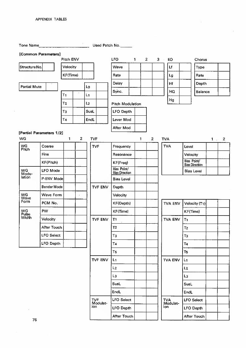
APPENDIX TABLES
Tone Name Used Patch No.
[Common Parameters]
Pitch ENV LFO EQ Chorus
Structure No. Velocity
KF(Time}
Partial Mute
[Partial Parameters 1/2]
WG
Lo
Ti Li
T2 L2
T3 SusL
T4 EndL
Wave
Rate
Delay
Sync.
Pitch Modulation
TVF
WGPitch
Coarse
Fine
KF(Pitch)
WGModu-lation
LFO Mode
P-ENV Mode
Bender Mode
WGWaveForm
Wave Form
PCM No.
WGPulseWidth
PW
Velocity
After Touch
LFO Select
LFO Depth
76
Lf
Lg
Hf
HQ
Hg
Type
Rate
Depth
Balance
LFO Depth
Lever Mod
After Mod
TVF Frequency
Resonance
KF(Freq)
Bias Point/
Bias Direction
Bias Level
TVF ENV Depth
Velocity
KF{Depth)
KF(Time)
TVF ENV Ti
T2
T3
T4
T5
TVF ENV Li
L2
L3
SusL
EndL
TVFModulat-ion
LFO Select
LFO Depth
After Touch
TVA 1 . 2
TVA Level
Velocity
Bias Point/
Bias Direction
Bias Level
TVA ENV Velocity (Ti)
KF(Time)
TVA ENV Ti
T2
T3
T4
T5
TVA ENV Li
L2
L3
SusL
EndL
TVAModulat-ion
LFO Select
LFO Depth
After Touch
[^Roland
so MIDI
Implementation
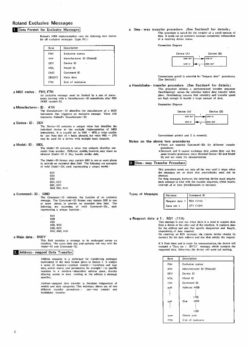
Roland Exclusive Messages
[Data Format for Exclusive Messages # One- way transfer procedure (See Sections for details.)
This procedure is suiit'd for Iho transfer of a small amount of
Roland's MID! implujiicnlalion uses ihc following data formal data. It sends out an exclusive nicsssRe completely independent
for all exclusive mcssaees <iype IV) : of a receiving device status.
Byte Descriotion
FOH Exclusive status
41H Manufacturer ID (Roland)
DEV Device ID
MDL Model ID
CMO Command ID
[BODY] Main data
F7H End of exclusive
Connection Diagram
Device <A) Device (B)
WlIM WIT WOl IN
l/IOI OUT
# MIDI status : FOH. F7HAn exclusive message must be flanked by a pair of status
codes, slatting with a .Manufacturer-ID immediately after FOH<MII)I vcrsionl.O).
# Manufacturer- ID : 41HThe iV^anufacturcr-lD identifies the manufacturer of a MIDI
inslrumeni that triggcres an exclusive message. Value 41H
reprcsenls Roland's Manufacturer-ID.
# Device- ID : DEVThe Dcvice-ID contains a unique value that identifies the
individual device in the multiple implementation of MIDI
instruments. It is usually set to OOH - OFH, a value smaller
by one than that of a basic channel, but value OOH — IFHmay be used for a device with multiple basic channels.
# Model- ID : MDLThe Modcl~ID contains a value that uniquely identifies one
model from another. Different models, however, may share an
identical Model- ID if they handle similar data.
The iModel-lD format may contain OOH in one or more places
to provide an extended data field. The following are examples
of valid Model -IDs, each representing a unique model :
01
H
02H03HOOH. GUI0011. 0211
OOH, OOH, OIH
Connectionai point2 is essential for "Request data" procedures.
(See Sections.)
# Handshake- transfer procedure (See Section4 for details.)
This procedure initiates a predetermined transfer sequence
(handshaking) across the interface before' data transfer takes
place. Handshaking ensures that reliability and transfer speed
are high enough to handle a large amount of data.
Connection Diagram
Device (A) Device (B)
UltH OIJT
WIOI in
UIDI IN
MIIM OUT
Conncctionat pointsl and 2 is essential.
Notes on the above two proceduresThere are separate Command --IDs for different transfer
procedures.
*DevicesA and B cannot exchange data unless they use the
same transfer procedure, share identical Device— ID and Model
ID, and are ready tor communication.
One- way Transfer Procedure
This procedure sends out data all the way until it stops whenthe messages are so short that answerbacks need not be
checked.
For long messages, however, the receiving device must acquire
each message in time with the transfer sequence, which inserts
intervals of at least 20milliseconds in between.
# Command- ID CMDThe Command - ID indicates the function of an exclusive
message. The Command— ID format may contain OOH in one
or more places to provide an extended data field. Thefollowing arc examples of valid Command- IDs . each
representing a unique function :
Types of Messages Message Command ID
Request data 1
Data set 1
RQl (11H)
DTI (12H)
Olil
02H03H0011, OtHOOil, 02H0011, 0011, 0111
# Main data : BODYThis field contains a message to l>e exchanged across an
interface. The exact data sixc and contents will vary with the
Model-ID and C<immand-ID.
Q||Address- mapped Data Transfer
Address mapping is a technique for transferring messages
conforming to the data format given in Section I. it assigns
a scries of memory -resident records— waveform and tone
data, switch status, and parameters, for example— to specific
locations in a machine -dependent address space, thereby
allowing access to data residing at the address a message
specifies.
Address-mapped d^ta transfer is therefore independent of
models and data categories. This technique allows use of two
different transfer procedures : one-way transfer and
handshake transfer.
# Request data # 1 : RQ1 (11 H)This message is sent <jut when there is a need to acquire data
from 3 device at the other end of the interface. It contains data
for the address and sixo that specify designation and length,
respectively, of data required.
On receiving an RQl message, the remote device checks its
memory for the data address and size that satisfy the request.
If it finds them and is ready for communication, the device will
transmit a "Data set 1 (DTI)" message, which contains the
requested data. Otherwise, the device will send out nothing.
Byte Description
FOH Exclusive status
41.H Manufacturer ID (Roland)
DEV Device ID
MDL Model ID
IIH Command ID
aaH Address MSB
I.SB
She MSB
LSD
sum Check sum
F7H End of e?!CiiiSive
2
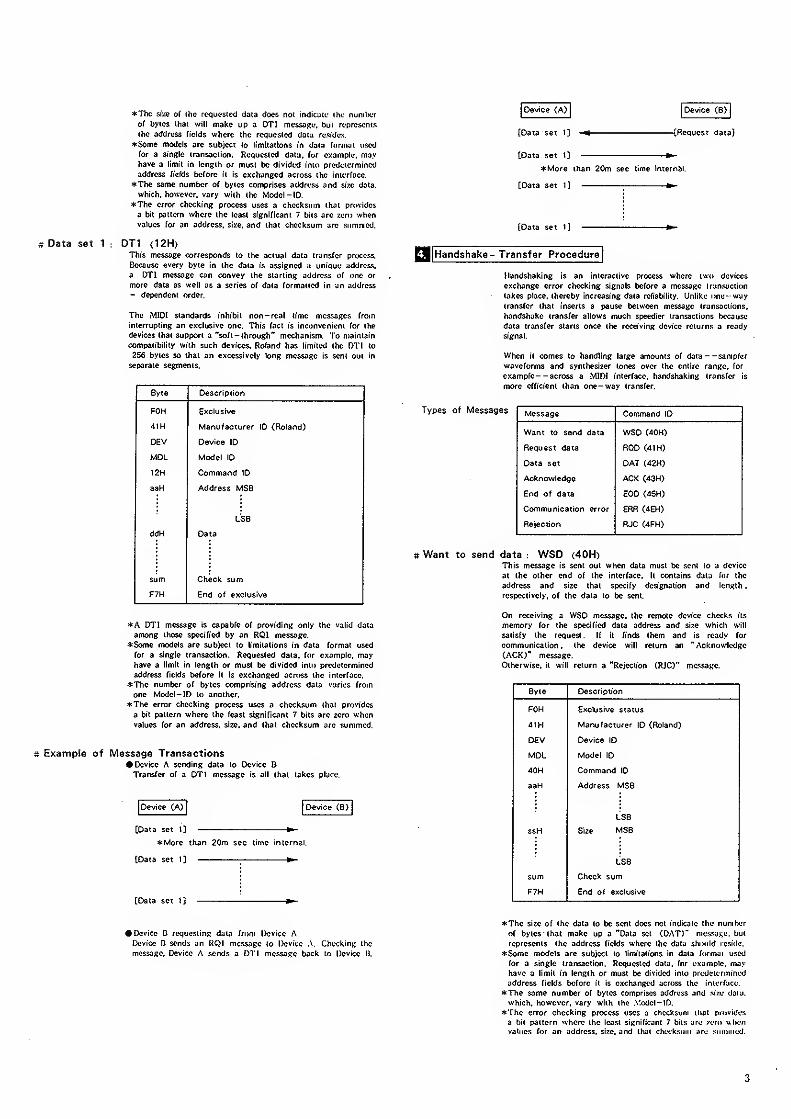
Data set 1
The size of the rc^guestcd daia does not indicate the nunil>cr
of byics that wilt make up a DTI mtssaRi;. but represents
the address fields where the requested data residys.
*Some models are subject to limitations in data format used
for a sioRle transaction. Requested data, tor example, mayhave a limit in length or must be divided into predetermined
address fields before it is exchanged across the interface.
The same number of bytes comprises address and size data,
which, however, vary with the Model -ID.
*The error choekinft process uses a checksum that provides
a bit pattern where the least significant 7 bits are zero whenvalues tor an address, size, and that checksum are summed.
DTI (12H)This message corresponds to the actual data transfer process,
liecausc every byte in the data is assigned a unique address,
a DTI message can convey the starting address of one or
more data as well as a scries of data formatted in an address- dependent order.
The MIDI standards inhibit non - real lime messages from
interrupting an exclusive one. This fact is inconvenient for the
devices that support a "soft -through" mechanism. To maintain
compatibility with such devices, Roland has limited the DTI to
256 bytes so that an excessively long message is sent out in
separate segments.
Device (A) Device (B)
Byte Description
FOH . Exclusive
dm Manufacturer ID (Roland)
DEV Device ID
MOL Model \D
12H Command ID
aaH Address MSB
LSB
ddH Data
sum Check sum
F7H End of exclusive
*A DTI message is capable of providing only the valid data
among those specified by an RQl message.
Some models are subject to limitations in data format used
for a single transaction. Requested data, for example, mayhave a limit in length or must be divided into predetermined
address fields before it is exchanged across the interface.
*The number of bytes comprising address data varies from
one Model-ID to another.
*The error checking process uses a checksum that provides
a bit pattern where the least significant 7 bits arc zero whenvalues for an address, size, and that checksum arc summed.
Example of Message TransactionsDevice A sending data to Device BTransfer of a DTI message is all that takes place.
Device (A) Device C8>
[Data set 1] ^More than 20m sec time internal.
(Data set 1] ^
(Data set 1] [Request data)
(Data set Ij ^More than 20m sec time internal.
[Data set i] ^
[Data set I]
[3i|HaniJshake- Transfer Procedure
Handshaking is an interactive process where two devices
exchange error checking signals before a message transaction
takes place, thereby increasing data reliability. Unlike one-waytransfer that inserts a pause between message transactions,
handshake transfer allows much speedier transactions because
data transfer starts once the receiving device returns a ready
signal.
When it comes to handling large amounts of data— sampler
waveforms and synthesizer tones over the entire range, for
example— across a MIDI interface, handshaking transfer Is
more efficient than one— way transfer.
Types of Messages Message Command ID
Want to send data WSD (dOH)
Request data ROD (41 H)
Data set OAT C42H)
Acknowledge ACK C43H)
End of data GOD C45H)
Communication error ERR (dEH)
Rejection RJC C4FH)
# Want to send data : WSD (40H)This message is sent out when data must be sent to a device
at the other end of the interface, it contains data for the
address and size that specify designation and length
.
respectively. o( the data to be sent.
On receiving a WSD message, the remote device checks its
memory for the specified data address and si?.e which will
satisfy the request. If it finds them and is ready for
communication . the device will return an " Acknowledge
(ACK)" message.
Otherwise, it will return a "Rejection (RJC)" mc.isajte.
[Data set 1]
Byte Description
FOH Exclusive status
dlH Manufacturer ID (Roland)
DEV Device ID
MDL Model ID
40H Command ID
aaH Address MSB
LSB
ssH Size MSB
LSB
sum Check sum
F7H End of exclusive
• Device B requesting data from Device .A
Device B sends an RQI message to Device .\. Checking the
message. Device A sends a DTI message back to Device U.
The size of the data to be sent docs not indicate the numberof bytes that make up a "Data set (DAT)' message, but
represents the address fields where the data should reside.
4:Somc models are subject to limitations in data format used
for a single transaction. Requested data, for example, mayhave a limit in length or must be divided into predetermined
address fields before it is exchanged acr<iss the interface.
The same number of bytes comprises address and siw data,
which, however, vary with the .\'odcl-lD.
The error checking process uses a checksum ihut provides
a bit pattern where the least significant 7 bits are zero whenvalues /or an address, size, and that checksum ;>re .summed.
3
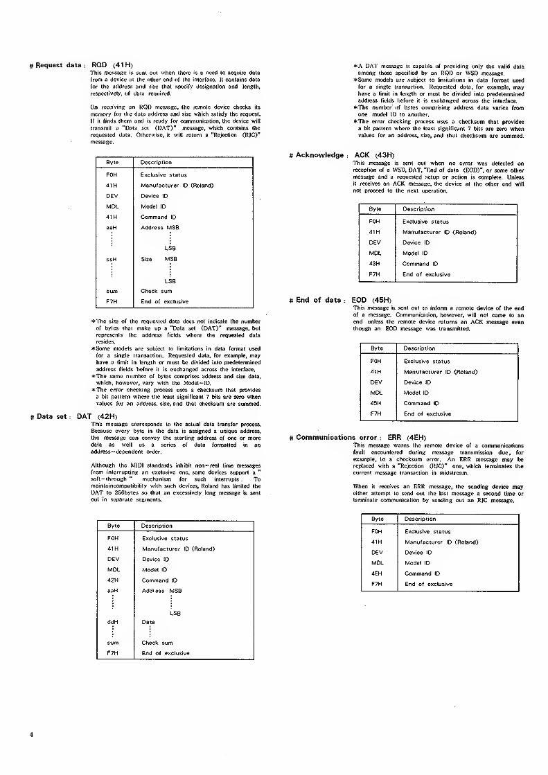
# Request data : ROD (41 H>This nicssaKo is sunt out when ihcre is a rvx<S to acquire data
from <Icvici,' :ii ihe (Hficr end of ihc interface. It contains dala
for the address and size that specify dcsifinaiion and length,
respectively, of data required.
On receiving an HC3i> nies.sage, the remote device checks its
memory tor the data address and size which satisfy the request.
If it finds them and is ready for communication, the device will
transmit a "Data set (DAT)" message, which contains the
requested data. Otherwise, it will return a "Rejection <R]C)"
message.
Syte Description
FOH Exclusive status
4tH Manufacturer ID (Roland)
DEV Device ID
MDL Model ID
41H Command ID
aaH Address MSB
ssH Size MSB
LSB
sum Check sum
F7H End of exclusive
*The size of the requested data does not indicate the numberof bytes that make up a "Data set (DAT)" message, but
represents the address fields where the requested data
resides,
4:Some models arc subject to limitations in data format used
for a single transaction. Requested data, for example, mayhave a limit in length or must be divided into predetermined
address fields before it is exchanged across the interface.
*The same number of bytes comprises address and size data,
which, however, vary with the Model— ID,
*The error checking process uses a checksum that provides
a bit pattern where the least significant 7 bits are zero whenvalues for an address, size, and that checksum are summed,
# Data set : DAT (42H)This message corresponds to the actual data transfer process.
Because every byte in the data is assigned a unique address,
the message can convey the starting address of one or moredata as well as a scries of dala formatted in anaddress -dependent order.
Although the MIDI standards inhibit non— real time messagesfrom interrupting an exclusive one. some devices support a
"
soft-through " mechanism for such interrupts . Tomaintaincompatibility with such devices, Roland has limited the
DAT to 2SCbytes so that an excessively long message is sent
out in separate segments.
Byte Descrlotion
FOH Exclusive status
dlH Manufacturer ID (Roland)
DEV Device ID
MDL Model ID
42H Command ID
aaH Address MSB
LSB
ddH Data
sum Check sum
F7H End of exclusive
*A DAT message is capal)le of providing only the valid dataamong those specified by an RQD or WSD message.
*Some models are subject to limitations in data formal used
for a single iransaclion. liequesled dala. for example, mayhave a limit in length or must be divided into predetermined
address fields Ix^fore it is exchanged across the interface.
*The number' of bytes comprising address data varies from
one model ID to another.
*The error checking process uses a checksum that provides
a bit pattern where the least significant 7 bits are zero whenvalues for an address, si/e. and that checksum are summed.
# Acknowledge : ACK (43H)This message is sent out when no error was delected onreception of a WSI), DAT, "find of data (EOD)". or some other
message and a requested setup or action is complete. Unlessit receives an ACK message, the device at the other end will
not proceed to the next operation.
Byte Description
FOH Exclusive status
41H Manufacturer ID (Roland)
DEV Device ID
MDL Model ID
43H Command ID
F7H End of exclusive
# End of data : EOD (45H)This message is sent out to inform a remote device of the endof a message. Communication, however, will not come lo anend unless the remote device returns an ACK message eventhough an EOD message was transmitted.
Byte Description
FOH Exclusive status
41H Manufacturer ID (Roland)
DEV Device ID
MDL Model ID
45H Command 10
F7H End of exclusive
# Communications error : ERR (4EH)This message warns the remote device of a communicationsfault encountered during message transmission due, for
example, to a checksum error. An ERR message may be
replaced with a "Rejection (IIJC)" one, which terminates the
current message transaction in midstream.
When it receives an ERR message, the sending device maycither attempt to send out the last message a second time or
terminate communication by sending out an RJC message.
Byte Description
FOH Exclusive status
41H Manufacturer ID (Roland)
DEV Device ID
MDL Model ID
4EH Command ID
F7H End of exclusive
4
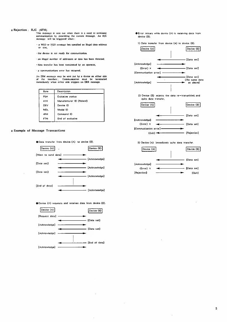
# Rejection : RJC (4FH>I'his message is sent out when there is a need to terminate
communicuiion by overriding the current message. An RJC
mcssatie will be irigRcrcd when :
a WSD or liQD message has specified an illegal data address
or sixc,
(he deviee is noi ready for communication.
an illegal number of addresses or data has been detected,
•data transfer has been terminated by an operator.
a communications error has occurred.
An ERR message may be sent out by a device on either side
of ihe interface . Communication must be terminated
immediately when either side triggers an ERR message.
# Example of Message Transactions
# Error occurs while device (A) is receiving data from
device (8).
1> Data transfer from device (A) to device (B).
Device (A) Device (B>
[Acknowledge]
(Error) x
[Communication error]
[Acknowledge]
- [Data set]
- [Data set]
- [Data set]
(the same dataas above)
Byte DescriDtion
FOH
41H
Exclusive status
Manufacturer ID (Roland)
2) Device CB) rejects the data re— transmitied, and
quits data transfer.
DEV Device ID Device <A) Device (B)
MDL Model ID
-JFH Command ID[Data set]
F7H End of exclusive[Acknowledge]
(Error) x
(Communication error]-
(Qult)-*-
[Data set]
[Rejection]
Data transfer from device (A) to device (B).
Device (A)
(Want to send data]
[Data set)
[Data set)
[End of data)
Dewce (B)
[Acknowledge)
[Acknowledge)
[Acknowledge)
[Acknowledge)
3) Device (A) immediately quits data transfer.
Device (A)
[Acknowledge)
(Error) x
[Rejection)
Device (B)
[Data set]
[Data set]
(Quit)
• Device (A) requests and receives data from device (B).
Device (A) Device (B)
[Request data)
[Acknowledge)
[Acknowledge]
[Acknowledge]
[Data set)
[Data set]
[End of data)
5
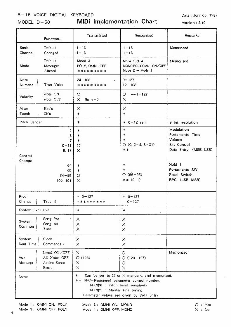
8-16 VOICE DIGITAL KEYBOARD
MODEL D-50 MIDI Implementation ChartDate : Jun. 05. 1987
Version ; 2.10
Function-Transmitted Recognized Remarks
Basic Default
Channel Changed
1-16
1-16
1-16
1-16Memorized
Default
Mode Messages
Allcred
MOQe o
POLY. OMNI OFF
Mode 1, -3, 4
MONO.POLY.OMNI ON/OFFMode 2 — Mode 1
Memorized
Note
Number '• True Voice
24-108 0-12712-108
.. Note ON
Velocity „„„Note OFF
OX 9n v=0
O v=1-127
X
After Key's
Touch Ch's
X*
X*
Pitch Bender * * 0-12 semi 9 bit resolution
1
5
7
0-31
6. 38
Control
Change
64
65
64-95
100. 101
*
*
*
OX
*
*
oX
*
*
*
O (0. 2-4. 8-31)
* *
*
*
O (66-95)
** (0. 1)
Modulation
Portamento Time
Volume
Ext Control
Data Entry (MSB, LSB)
Hold 1
Portamento SWPedal Switch
RPC (LSB. MSB)
Prog
Change True #
* 0-127 * 0-127
0-127
System Exclusive * *
System
Common
Song Pos
Song sel
Tune
XXX
XXX
System
Real Time
iClock
: CommandsXX
XX
Aux :
Messagei
Local ON/OFFAll Notes OFFActive Sense
Reset
XO (123)
XX
oO (123-127)
oX
Memorized
Notes * Can be set to O or X manually, and memorized.
** RPC=Registered parameter control number.
RPC#0 : Pitch bend sensitivity
RPC#1 ; Master fine tuning
Parameter values are given by Data Entry.
Mode 1 : OMNI ON. POLY Mode 2 : OMNI ON. MONO O : Yes
Mode 3 : OMNI OFF. POLY Mode 4 : OMNI OFF. MONO X : No6
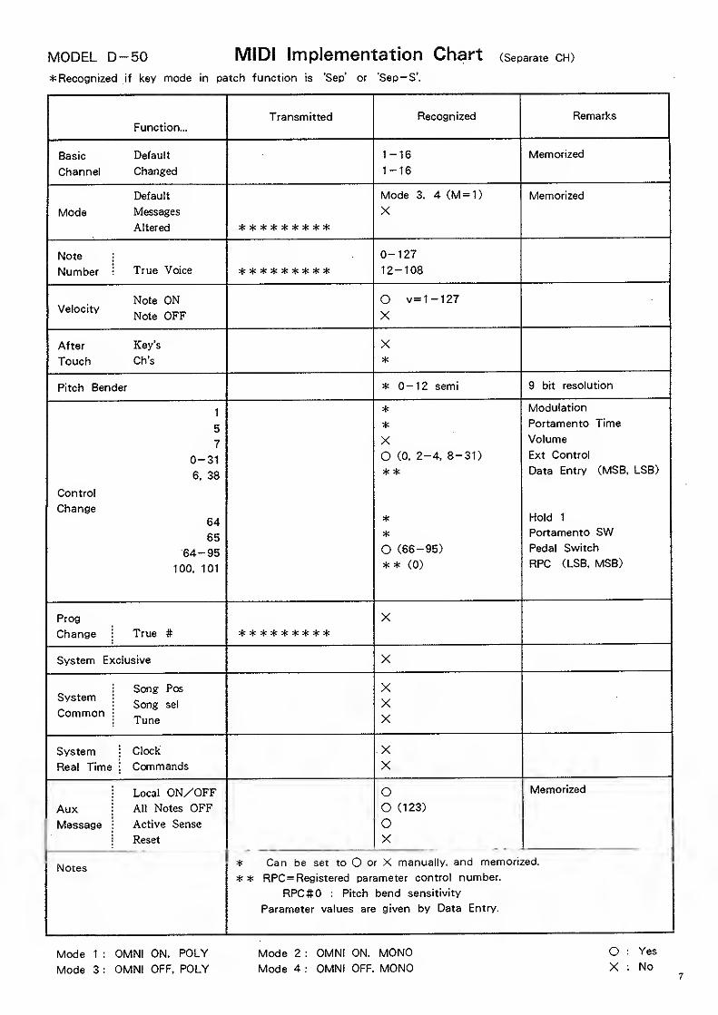
MODEL D-50 MIDI Implementation Chart (Separate CH)
Recognized if key mode in patch function is 'Sep' or 'Sep-S'.
Function-Transmitted Recognized Remarks
Basic Default
Channel Changed
1-16
1-16
Memorized
Default
Mode Messages
Altered
Mode 3. 4 (M = 1)
XMemorized
Note
Number True Voice
0-127
12-108
Note ONVelocity
i\oxe yjc c
O v-1-127X
After Key's
Touch Ch's
X*
Pitch Bender * 0-12 semi 9 bit resolution
1
5
7
0-31
6, 38
Control
Change64
65
64-95
100. 101
*
*
XO (0. 2-4. 8-31)
* *
*
*
O (66-95)
* * (0)
Modulation
Portamento Time
Volume
Ext Control
Data Entry (MSB, LSB)
Hold 1
Portamento SWPedal Switch
RPC (LSB, MSB)
Prog
Change True #
X
System Exclusive X
System
Common
Song Pos
Song sel
Tune
XXX
System \Clock
Real Time i Commands
xX
Aux
Message
Local ON/OFFAll Notes OFFActive Sense
Reset
oO (123)
OX
Memorized
Notes* Can be set to O or X manually, and memorized.
RPC=Registered parameter control number.
RPC#0 : Pitch bend sensitivity
Parameter values are given by Data Entry.
Mode 1 : OMNI ON, POLY Mode 2 : OMNI ON. MONO O : Yes
Mode 3 : OMNI OFF. POLY Mode 4 : OMNI OFF. MONO X : No
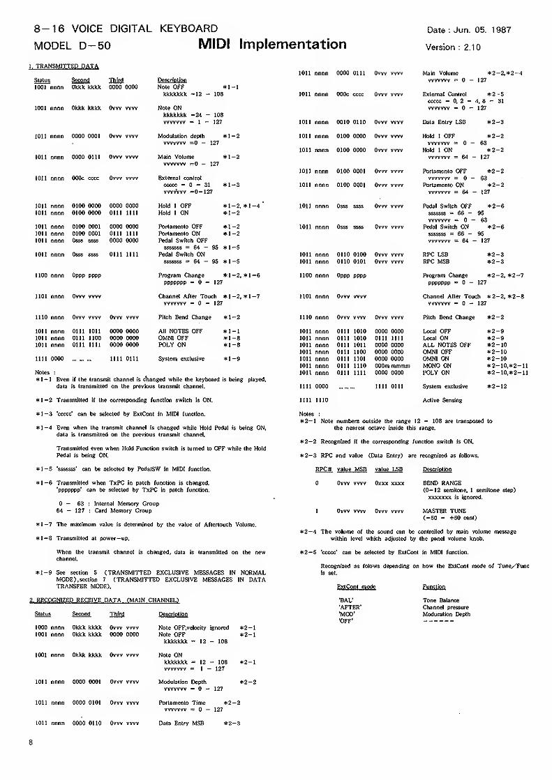
8-16 VOICE DIGITAL KEYBOARD
MODEL D-50 MIDI ImplementationDate : Jun. 05. 1987
Version : 2.10
1. TRANSMITTED DATA
Status Second Third
1011 nnnn 0000 0111 Owv vvvv Main Volume *2-2,*2-Avvvvvvv - - 127
1001 nnnn Okkk kkkk 0000 0000 Note OFF *1 -1
kkkkkkk =12 - 108 1011 nnnn 000c cccc Ovw vvvv External Control *2 -5
ccccc = 0, 2 - 1, 8 - 31
1001 nnnn Okkk kkkk Owv vvvv Note ON vvvvvvv = — 127
kkkkkkk =24 - 108
vvvvvvv = J — 127 1011 nnnn 0010 0110 Ovvv vvvv Data Entry USB *2-~3
1011 nnnn 0000 0001 Owv WW Modulation depth *1 -2 1011 nnnn 0100 0000 Ovw vvvv Hold I OFF *2--2
vvvvvvv =0 - 127 vvvvvvv = — 63101! nnnn 0100 0000 Ovw vvvv Hold 1 ON *2--2
1011 nnnn 0000 0111 Ovw vvvv Main Volume *1 -2 vvvvvvv = 64 -- 127
vvvvvvv =0 - 127
1011 nnnn 0100 0001 Ovvv WW Portamento OFF *2--2
1011 nnnn 000c cccc Owv vvvv External control vvvvvvv = - 63
ccccc = 0-31 *1 -3 1011 nnnn 0100 0001 Ovvv vvvv Portamento ON *2--2vvvvvvv =0—127 vvvvvvv = 64 -- 127
1011 nnnn 0100 0000 0000 0000 Hold 1 OFF *1 -2, *l-4'
1011 nnnn Osss ssss Ovw vvvv Pedal Switch OFF *2 -61011 nnnn 0100 0000 0111 1111 Hold I ON *1 -2 sssssss = 66 - 95
vvvvvvv = - 631011 nnnn 0100 0001 0000 0000 Portamento OFF *1 -2 1011 nnnn Osss ssss Ovw WW Pedal Switch ON *2 -61011 nnnn 0100 0001 0111 1111 Portamento ON *1 -2 sssssss = 66 - 95
1011 nnnn Osss ssss 0000 0000 Pedal Switch OFF vvvvvvv = 64 -- 127
sssssss = 64-95 *1 -5ion nnnn Osss ssss GUI 1111 Pedal Switch ON 1011 nnnn 0110 0100 Ovw WW RPC LSB *2--3
sssssss = 64-95 *1 -5 ion nnnn 0110 0101 Ovw WW RPC MSB *2 -3
1100 nnnn Oppp PPPP Program Change *1 -2, *l-6 1100 nnnn Oppp pppp Program Change *2--2, *2
1101 nnnn Ovw vvvv
PPPPPPP =0—127
Channel After Touch *l-2, *l-7vvvvvvv = — 127
1101 nnnn Ovvv vvvv
PPPPPPP =0-127
Channel After Touch *2-2, *2-8vvvvvvv =0—127
1110 nnnn Ovvv vvvv Ovvv WW Pitch Bend Change *l-2 1110 nnnn Ovw vvvv Ovw vvvv Pitch Bend Change *2-2
1011 nnnn 0111 ton 0000 0000 All NOTES OFF *l-l 1011 nnnn 0111 1010 0000 0000 Local OFF *2-91011 nnnn 0111 1100 0000 0000 OMNI OFF *l-8 1011 nnnn oni 1010 0111 nil Local ON *2-91011 nnnn 0111 nil 0000 0000 POLY ON *l-8 1011 nnnn 0111 1011 0000 0000 ALL NOTES OFF *2-10
1011 nnnn 0111 1100 0000 0000 OMNI OFF *2- 10
1111 0000 nil oni System exclusive *l-9 ton nnnn 0111 1101 0000 0000 OMN! ON *2- 10
1011 nnnn 0111 1110 000m mmmm MONO ON *2-10,*2-nNotes : ion nnnn 0111 1111 0000 0000 VOLY ON *2- 10,*2-11*I-1 Even if the transmit channel is clianged while the keyboard is being played,
data is transmitted on the previous transmit channel. nil 0000 nil 0111 System exclusive *2-12
*l-2 Transmitted if the corresponding function switch is ON. lilt 1110 Active Sensing
*l-3 'ccccc' can be selected by ExtCont in MIDI function.
*l-4 Even when the transmit channel is changed while Hold Pedal is being ON,data is transmitted on the previous transmit channel.
Transmitted even when Hold Function switch is turned to OFF while the Hold
Pedal is being ON,
*l-5 'sssssss' can be selected by PedalSW in MIDI function.
*l-6 Transmitted when TxPC in patch function is changed,
'ppppppp' can be selected by TxPC in patch function.
- 63 : Internal Memory Group64 - 127 : Card Memory Group
*l-7 The maximum value is determined by the value of Aftertouch Volume.
*1~8 Transmitted at power-up.
When the transmit channel is changed, data is transmitted on the newchannel.
*l-9 See section 5 (TRANSMITTED EXCLUSIVE MESSAGES IN NORMALMODE), section 7 (TRANSMITTED EXCLUSIVE MESSAGES IN DATATRANSFER MODE).
2. RECOGNIZED RECEIVE DATA (MAIN CHANNEL)
Status Second Third
1000 nnnn Okkk kkkk Ovvv vvvv
1001 nnnn Okkk kkkk 0000 0000
1001 nnnn Okkk kkkk Ovvv ww
ion nnnn 0000 0001 Ovvv vvvv
1011 nnnn 0000 0101 Ovvv vvvv
Description
Note OFF,velocity ignored
Note OFFkkkkkkk = 12 - 108
Note ONkkkkkkk = 12 - 108vvvvvvv = 1 — 127
Modulation Depthvvvvvvv = — 127
*2-l*2-l
*2-l
*2-2
Notes :
*2-I Note numbers outside the range 12 - 108 are transposed to
the nearest octave inside this range.
*2-2 Recognized if the corresponding function switch is ON.
*2-3 RPC and value (Data Entry) are recognized as follows.
RPC# value MSB value LSB Description
Ovvv vvvv Oxxx xxxx BEND RANGE(0—12 semitone, 1 semitone step)
xxxxxxx is ignored.
1 Ovw vvvv Ovvv vvvv MASTER TUNE(-50 - +50 cent)
*2-4 The volume of the sound can be controlled by main volume message
within level which adjusted by the panel volume knob.
*2-5 'ccccc' can be selected by ExtCont in MIDI function.
Recognized as folows depending on how the ExtCont mode of Tune/Funcis set.
Ext<>>nt mode
'BAL'
'AFTER'MOD''OFF'
Function
Tone Balance
Channel pressure
Moduration Depth
Portamento Time *2-2vvvvvvv = — 127
1011 nnnn 0000 0110 Owv vvvv Data Entry MSB
8
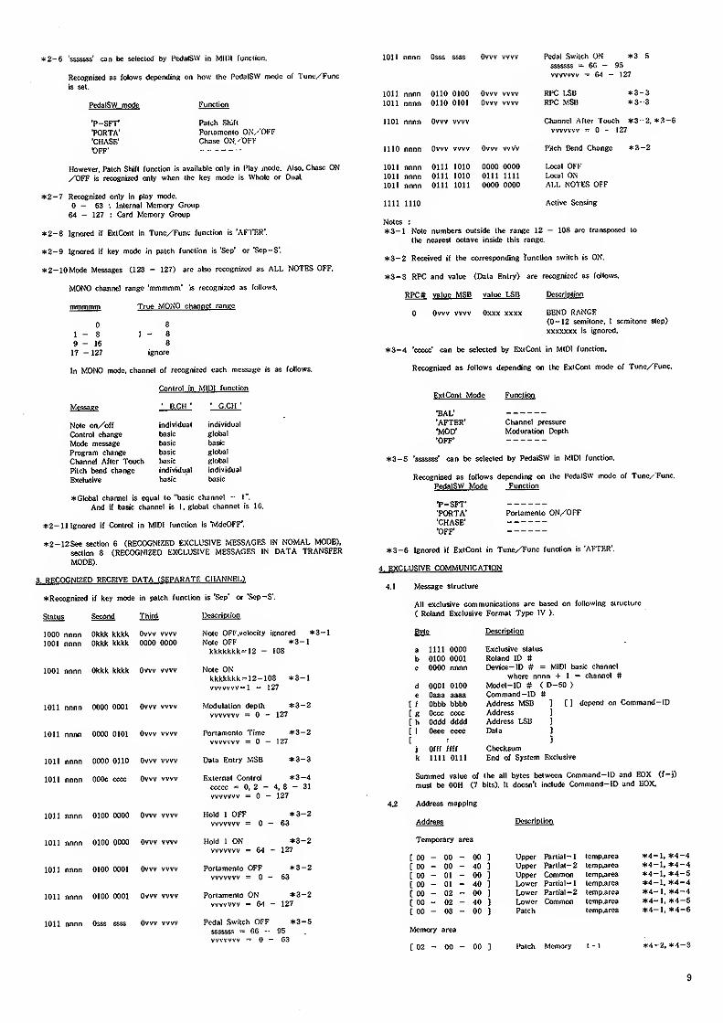
*2-6 'ssss&ss' can be selected by PedalSW in Willi function.
Recognized as folows depending on how the PcdalSW mode of Tune/Func
is set.
PedalSW mode
'P-SFT'
•PORTA''CHASE'
'OFF'
Function
Patch Shift
Porlonicnto OiN'/'OI'F
Chase ON. 'OFF
However, Patch Shift function is available only in Play mode. Also, Chase ON/OFF is recognized only when the key mode is Whole or Dual.
*2-7 Recognized only in play mode.
- 63 : Internal Memory Group
64 - 127 : Card Memory Group
*2-8 Ignored if ExtCont in Tune/Func function is 'AnT.R'.
*2-9 Ignored it key mode in patch function is 'Sep' or 'Sop-S'.
*2-10Mode Messages (123 - 127) are also rccogni^icd as ALL NOTES OFF.
MONO channel range 'mmmmni' is recognized as follows.
mmmmm True MONO channel range
8
1 - 8
9-1617 -127
I - 8
8
ignore
In MONO mode, channel of recognized each message is as follows.
Control in MIDI function
' B.CH '' G.CH
'
Message
Note on/off
Control change
Mode message
Program change
Channel After Touch
Pilch bend change
Exclusive
individual
basic
basic
basic
basic
individual
basic
individual
global
basic
global
global
individual
basic
*Glotial channel is equal to "basic channel - 1".
And if basic channel is l.g'otjal channel is 16.
*2-ll Ignored if Control in MIDI function is 'ivIdeOFF'.
*2-12See section 6 (RECOGNIZED EXCLUSIVE MESSAGES IN NOMAL MODE),
section 8 (RECOGNIZED EXCLUSIVE MESSAGF„S IN DATA TRANSFER
MODE).
8. RECOGNIZED RECEIVE DATA fSEPARATK CHANNEL)
Recognized if key mode in patch function is 'Sep' or 'Sep-S'.
Status Second Third
1000 nnnn Okkk kkkk Ovvv vvvv
1001 nnnn Okkk kkkk 0000 0000
1001 nnnn Okkk kkkk Ovvv vvvv
1011 nnnn 0000 0001 Ovvv vvvv
1011 nnnn 0000 0101 Ovvv vvvv
1011 nnnn 0000 0110 Ovvv vvvv
1011 nnnn OOOc cccc Ovw vvvv
lOn nnnn 0100 0000 Ovvv vvvv
1011 nnnn 0100 0000 Ovvv vvvv
1011 nnnn 0100 0001 Ovvv vvvv
1011 nnnn 0100 0001 Ovvv vvvv
1011 nnnn Osss ssss Ovvv vvvv
l>cscriplion
Note OFF.velocity ignored *3-lNote OFF *3-lkkkkkkk----I2 - 108
Note ONkkkkkkk = 12-108 *3-lvvvvvvv— 1 — 127
Modulation depth *3-2vvvvvvv = - 127
Portamento Time *3-2vvvvvvv = - 127
Data Entry MSB *3-3
External Control *3-4ccccc = 0, 2 - 4, 8 - 31
vvvvvvv = - 127
Hold 1 OFF *3-2vvvvvvv =0—63
Hold 1 ON *3-2vvvvvvv =64-127
Portamento OFF *3-2vvvvvvv =0—63
Portamento ON *3-2vvvvvvv = G4 — 127
Pedal Switch OFF *3-5sssssss = 06 - 95vvvvvvv — — 63
1011 nnnn Osss ssss Ovvv vvvv Pedal Switch ON *3 S
sssssss - 6G - 95
vvvvvvv — (i4 — 127
1011 nnnn 0110 0100 Ovvv vvvv RFC I^IJ *3-31011 nnnn Olio 0101 Ovvv vvvv RPC MSiJ *3- 3
1101 nnnn Ovvv vvvv Channcl After Touch *3--2,
vvvvvvv = - 127
1110 nnnn Ovvv vvvv Ovvv vvvv Pitch Ifend Change *3--2
1011 nnnn OIU 1010 0000 0000 lxxa\ OFF1011 nnnn 0111 1010 0111 1111 Local ON1011 nnnn 0111 1011 0000 0000 ALL r<U 1 Vtr
nil 1110 Active Sensing
Notes :
*3- 1 Note numbers outside the range 12 - 108 arc transposed to
the nearest octave inside this range.
*3— 2 Received if the corresponding function switch is ON.
*3~3 RPC and value (Data Entry) are recognized as follows.
RPC# value MSB value LSB Dcscriplion
Ovvv vvvv Oxxx xxxx BEND RANGE(0-12 semitone. 1 semitone step)
xxxxxxx is ignored.
*3-4 'ccccc' can be selected by ExtCont in MIDI function.
Recognized as follows depending on the ExiCont mode of Tune/Func.
ExtCont Mode
SAL''AFTER'
'MOD'•OFF*
Function
Channel pressure
Moduration Depth
*3—5 'sssssss' can be selected by PedaiSW in MIDI function.
Recognized as follows depending on the PedalSVV mode of Tune/ Func,
PedalSW Mode Function
T-SFT''PORTA''CHASE'
OFF'
Portamento ON/'OFF
3-6 Ignored if ExtCont in Tune/Func function is 'AFTKR',
4, EXCLUSIVE COMMUNICATION
4.1 Message structure
All exclusive communications are based on following siriicturc
( Roland Exclusive Format Type IV ).
Byte Description
a nil 0000 Exclusive status
b 0100 0001 Roland ID #c 0000 nnnn Device-ID # = MIDI basic channel
where nnnn I- 1 = channel #
d 0001 0100 Model-ID # ( D-50 )
e Oaaa aaaa (^mmand-lD #[f Obbb bW>b Address MSB ] [] depend on Command -ID
[ g Occc cccc Address ]
[ h Oddd dddd Address LSB ]
[ i Oeee eeee Data 1
[ : 3
j Offf ffff Checksumk nil OUl End of System Exclusive
Summed value of the all bytes between Command-ID and FOX (f-j)
must be OOH (7 bits). It doesn't include Command-ID and EOX,
4.2 Address mapping
Address
Temporary area
Descriptiwi
[ 00 - 00 - 00 ] Upper Partial-
1
temp.arca *4-l, *4-4
[ 00 - 00 - 40 ] Upper Partial-
2
temp.area *4-l, *4-4
e 00 - 01 - 00 ] Upper Common temp.area *4-l, *4~5
[ 00 - 01 - 40 ] Lower Partial-
1
tcmp,area *4-l, *4-4
[ 00 - 02 - 00 ] Lower Partial-2 temp.area *4-l, *4-4
( 00 - 02 - 40 ) Lower Common lemp.arca *4-l. *4-5
[ 00 - 03 - 00 1 Patch temp.arc3 *4-l, *4-6
Memory area
[ 02 - 00 - 00 Patch Memory 1 - 1 *4-2. *4-3
9
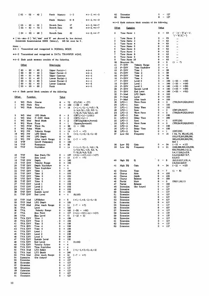
[ 02 - 03 - 10] Palch Memory 1-2 *4-2. *4-3
Patch Memory 8-8 *4-2. *4-3
[ 03 - 60 - 00 3 Reverb Data 17 *4-2, *4-7[ 03 - 62 - 78 1 Reverb Data 18 *4-2, *'l-7
[ 04 - oc - 08 3 Reverb Daia 32 *4-2. *4-7
* [ hh—mm— It ] 'hh'.'mm" and '11' arc showed by hex decimal.
Ohhhhhhh Ommmmmmm Olllllll (binary), MS bit must be .
Notes :
*4-I Transmitted and recognized in NORMAL MODE.
*4~2 Transmitted and recognized in DATA TRANSFER y.ODZ.
4-3 Each patch memory consists of the following.
Offset Descrioiion
[ 00 - 00 - 00 3 Upper Partial -
1
*4-4[ 00 - 00 - 40 3 Upper Partial -2 *4-4[ 00 - 01 - 00 3 Upper Ckwnmon *4-5[ 00 - 01 - 40 3 Lower Partial-
1
*4-4[ 00 - 02 - 00 3 Lower Partial -3 *4-4[ 00 - 02 - 40 3 Lower (^mmon *4-S[ 00 - 03 - 00 } Patch *4-fi
*4-4 Each partial block consists of the following.
Offset Function Value
WG Pitch Coarse _ 72 (C1,C#1 - C7)
1 WG Pitch Fine _ 100 (_50 - +50)2 WG Pilch Keyfollow 16 (-l.-l/2.-lX''.0-l ''8,
1/4,3/8,1.' 2,5,'8.3 '4.
7/8,1,5/4,3/2,2.51, s2)
3 WG Mod LFO Mode _ 3 (OFF,(+).(-),A&L)4 WG Mod P-ENV Mode _ 2 (OFF,(+).(-)
5 WG Mod Bend Mode _ 2 (OFF.Key foliow.Normal)
6 WG Wave Form 1 (Souare,Sawtoolh)
7 WG PCM Wave No. S9 (1 - 100)
8 WG Pulse Width 100
9 WG PW Velocity Range 14 (-7 - +7)10 WG PW LFO Select 5 ( + ]^_ l,+2,-2,+3.-3)11 WG PW LFO Depth 100
12 WG PW After totich Range 14 (-7 - +71
13 TVF Cutoff Frequency 100
14 TVF Resonance 30
15 TVF Keyfollow 14 (_ 1__ J /2,- 1, 4,0.1, ''8,
l/4,3/8,l.'2,5^ 8.3/'4,
7/8,1,5/4,3/2,2)
16 TVF VAr^ Pnjnt yVfiT 12717 TVF n M
TUP PWV Depth u I vU1Qiff Velocity Range AV mn
TVP PMV n
TVP PWV Time Keyfollow UTVP PMV1 V r til V Time 1 1 no
Jo T\fP PW Time 2AU lUU
TVP PMV Time 3 1 ^n
25 TVF ENV Time 4 100
26 TVF ENV Time 5 10027 TVF ENV Uvel 1 100
28 TVP ENV Level 2 100
29 TVF ENV Level 3 100
30 TVF ENV Sustain Level 100
31 TVF ENV End Level I (0,100)
32 TVF Mod LFOSelect 5 { + I,-l.+2,-2,+3,-3)
33 TVF Mod LFO Depth 100
34 TVF Mod After touch Range 14 (-7 - +7)35 TVA Uvel 100
36 TVA Velocity Range 100 (-50 - +50)37 TVA Bias Point 127 «A1-<C7,>A1->C7)38 TVA Kas Level 12 (-12 - 0)
39 TVA ENV Time 1 100
40 TVA ENV Time 2 . 100
41 TVA ENV Time 3 100
42 TVA ENV Time 4 100
43 TVA ENV Time 5 100
44 TVA ENV Level 1 100
45 TVA ENV Uvel 2 100
46 TVA ENV Uvel 3 100
47 TVA ENV Sustain Uvel 100
48 TVA ENV End Uvel 1 (0.100)
49 TVA ENV Velocity Follow 4
50 TVA ENV Time Keyfollow 4
51 TVA Mod LFO Select 5 { + l,-I,+ 2,-2.r3.-3)
52 TVA Mod LFO Depth too
53 TVA Mod After touch Range 14 (-7 - +7)54 Extension (for future) 127
55 Extension 127
56 Extension 127
57 Extension 127
58 Extension 127
59 Extension 127
60 Extension 127
61 Extension 127
62 Extension - 127
63 Extension - 127
*4-S Each common block consists of the following.
Offset Function Value
Tone Name 1- 63 (' '.'A'-'Z'.'a'-'z'.
•l'-*9','0','-')
1 Tone Name 2 - 63 —2 Tone Name 3 - 63
3 Tone .Name 4 - 63
4 Tone Name 5 - 63
5 T(Xie Name 6 - 63
6 Tone Name 7 - 63
7 Tone Name 8 - 63
8 Tone Name 9 - 63
9 Tone Name 10 - 63
10 Structure No. - 6 <1 - 7)
11 P-ENV Velocity Range - 2
12 P-ENV Time Keyfollow _ 4
13 P-ENV Time 1- 50
14 P-ENV Time 2 - 50
15 P-ENV Time 3 - 50
16 P-ENV Time 4 - 50
1? P-ENV Uvel - 100 (-50 - +50)
18 P-ENV Uvel 1- 100 (-50 - +50)
19 P-ENV Uvel 2 - 100 (-50 - +50)
20 P-ENV Sustain Uvel - 100 (-50 - +50)
21 P-ENV End Uvel - 100 (-50 - +50)
22 P-Mod LFO Depth - 100
23 P-Mod Uver - 100
24 P-Mod After touch — 100
25 LFO-1 Wave Form - 3 (TRI,SAW5QU,RND)26 LFO-1 Rate - 100
27 LFO-1 Delay Time - 100
28 LFO-1 Sync - 2 (OFF.ON.KEY)
29 LFO-2 Wave Form - 3 {TRiMW.SQU.RND)30 LFO-2 Rate - 100
31 LFO-2 Delay T^me - 100
32 LFO-2 Sync -! (OFF.0N)
33 LFO-3 Wave Form - 3 (TRfMW5QU.RND)34 LFO-3 Rate - 100
35 LFO-
3
Delay Time — 100
36 LFO-
3
Sync —1 (OFF,ON)
37 Uw EQ Frequency — 15 ( 63, 75, 88,105,125,
350,420,500,600.700,
840 )
38 Low EQ Gain — 24 (-12 - +J2)39 Uw EQ Frequency - 21 (250,300,350,420.500,
600.700,840.1.0.1.2,
1.4,1,7,2.0,2,4,2.8,
3.4.4.0,4.8,5.7.6.7.
8.0.9.5)
40 High EQ Q - 8 (OJ.0.5.0.7.1,0.1.4,
2.0.3.0,4.2,6.0)
41 High EQ Gain - 24 (-12 - +12)
42 Chorus Type - 7 (I - 8)
43 Chorus Rate - 100
44 Chorus Depth - 100
45 Chorus Balance - 100
46 Partial Mule - 3 (00.01.10.11)
47 Partial Balance - 100
48 Extension (for future) - 127
49 Extension - 127
50 Extension - 127
51 Extension - 127
52 Extension 127
53 Extension 127
54 Extension 127
55 Extension 127
56 Extension 127
57 Extension 127
58 Extension 127
59 Extension 127
60 Extension 127
61 Extension 127
62 Extension 127
63 Extension 127
10
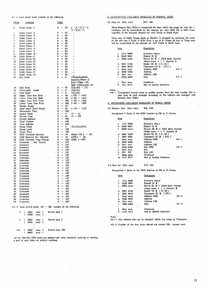
(1 patch fjlock consists of Ihe following. 5. •I'HANSyiri'lvl) KXCI.USiVK MHSSACKS IN NORMAL WODI-:
unction
» I'ilich Name 1
1 I'iilch Name 2
2 l';i(ch Name 3
:t I'altli Name 1
1 Taltli Name 5
.1 I'iUch Name 6<i i'uith Name 7
7 i'uicli Name 8
8 Patch Name 9
S) Patch Name 10
to I'alch Name It
1 r Pulch Name 12
i2 Patch Name 13
i;i Pa tell Name 14
M Patch Name 15
15 Patch Name 16
HI Patch Name 17
17 I'atch Name IS
IS Key Mode
Value
0-636.! Data sel (One way) DTI 12H
(' VA'-X'a'-V.'l'-'9V0V-')
63
63
63
63
63
63
63
63
63
63
63
63
63
63
6363
63
When Ucqucsi IJala (ROD is rccosnized, (he dala within the range sel with RO- I
messages will be transmitted on the channel set with MIDI CH in MIDI i"unc,
regardlss of the transmit channel set with TxCH in Patch Func,
When any of Patch Group. Bank or Number is changed by operating the panel
of the unit and if lixclu in MIDI Func is set to P—Dump, all data in Temp, area
will be transmitted on the channel sel with TxCH in Patch Func.
(Who!e.Dual.Split,
Soparalc,Wholc-S,
Dual-S,Split-US,
Split -LS,Separate-S)
Bvte Description
a nil 0000 Exclusive status
b 0100 0001 Roland ID #c 0000 nnnn Device ID # = MIDI basic channel
where nnnn + 1 = channel #d 0001 0100 Model-ID # ( D-50 )
0001 0010 Command-ID # ( DTI )
f Oaaa aaaa Address MSB *5-l« Obbb bbbb Address
h Occc cccc Address LSBi Oddd dddd Data *5-l
j Oecc ecce Checksumk till 0111 End o( System Exclusive
19 Split Point _ 60 (C2.C#2 - C7)
20 Portamento Mode 2 (U,L,UL) Notes :
21 Hold Mode 2 (U.L,UL) *5-l Transmitted several times in smaller portion than the total number 256 in
48 (_24 - +24) data byte of each message acrcoding to the address size assinged with
'>%J<(JkVvi 1 UJ lt# OJ 111 L 48 (-24 - +24) Request Data (ROD.
>jl upper Fone I'inc Tt^ne n 100
i.^ l^wer [one I'inc Tunc g 100 (—50 — +50) 6. RECOGNIZED EXCLUSIVE MESSAGES IN NOMAL MODE£v Bender Range 12')7 After touch Bend Range nV (—12 — +12) 6.1 Request Data (One way) RQl IIHJP Portamento Fmie 100
ty Outpirt Mode n 3 Recognized if Exclu in the MIDI futiclion is ON or P—Dump,30 Reverb Type - 31 (1 - 32)
o 1 Reverb Balance n 100 Bvte Description
Total Volume 100
33 Tone Balance 100 a 111 I 0000 Exclusive status
34 Chase Mode 2 (UL,ULL.ULU) b 0100 0001 Roland ID #35 Chase i-evel 100 c 0000 nnnn Device-ID # = MIDI basic channel
3(> Chase Time 100 where nnnn + 1 - channel #37 MIDI Transmit Channel 16 (Basic CH. I - 16) d 0001 0100 Model-ID # ( D-50 )
38 MIDI Separate Rev Channel 16 (OFF.I - 16) e 0001 0001 Command-ID # ( RQl )
39 MIDI Transmit Prog. Change 100 (OFF. 1-100) f Oaaa aaaa Address MSB *6-l10 Kxlension (for future) 127 8 Obhb bbbb Address
41 Extension 127 h Occc cccc Address LSB43 l^xlcnsion 127 i Oddd dddd Size MSB *6-l43 fixtension 127 i Occe eece Size
44 Extension 127 k Offf ffff Size I^B
45 Extension 127 1 Oggg gggg Checksum
4(i lixtension 127 m 1111 0111 End of System Excluave
47 Extension 127
48 1extension 127
49 Ivx tension 127 6.2 Data se (One way) DTI 12H
Extension 127
51 Extension 127 Recogni?XKJ if Exclu in the MIDI function is ON or P-Dump.
52 Extension 127
53 Extension 127 Oi Description
54 Extension 127
55 Extension 127 a till 0000 Exclusive status
56 Extension 127 b 0100 0001 Roland ID #57 Extension 127 c 0000 nnnn Device ID # = MIDI basic channel
58 Extension 127 where nnnn + 1 = channel #59 Extension 127 d 0001 0100 Modet-ID # ( D-50 )
60 Extension 127 e 0001 0010 Command-ID # ( DTI )
61 Extension 127 f Oaaa aaaa Address MSB *6-l
62 Extension 127 g Obbb bbbb Address
03 Extension 127 h
i
Occc cccc
Oddd dddd
Address LSBData *6-2
4-7 Each reverb block (17 - 32) consists of the following.
j Oecc ecce Checksum
! OOOO aaaa 1 Reverb data I k nil 0111 End of System Exclusive
1 0000 aaaa i
Notes :
2 1 0000 aaaa IReverb data 2 *6-l Any address si^e can be assinged within the range of Tcmp.area.
I0000 aaaa
0000 aaaa
0000 aaaa
*6-2 Number of the data bytes should not exceed 256. (except sum)
Reverb data 188
All the 188 data (376 byte) are related each other, therefore receiving or sending
a pari of data does not achieve anything.
11

7. TUAN'SMI ITliP KXCLUSIVfi MtaSAGES IN DATA TRANSFER MODK
No maitLT what tranmil channel is selected wi'ih TxCH in Patch Func, the niossaBes
are iransmiileU on the channel set with MIDI CH in MIDI Punc.
7.1 One way iransCcr
7.1,1 Data set DTI 12H
d Om 0100
e 0100 0011
( nil 0111
7.2.5 End of data
Byte
Modd-ID # ( D-50 )
Command-ID # { ACK )
End of System Exclusive
EOD 45H
Descripiion
a nil 0000smttttxl when 'ENTER' button is pressed in *Bulk Dump.O' b 0100 0001 Roland TD it
c 0000 nnnn Devic^-'IO # = MIDI basic channel
Bvie Dcscrinlion d 0001 0100 Modd-ID # ( D-50 )
e 0100 0101 Command-ID # ( EOD >
3 nil 0000 Exclusive status ( 1111 0111 End of System Exclusive
b 0100 0001 Roland ID »c 0000 nnnn Device-ID # = MIDI basic channel 7.2.G Rejection RJC 4FH
where nnnn + 1 = channel CcJ 0001 0100 Model-ID # (D-50) Bvte Descriotion
Q 0001 0010 Comnrand-ID # { DTI )
f Oaaa aaaa Address MSB *7-I a nil 0000 Exclusive status
s Obbb bbbb Address b 0100 0001 Roland ID #h Occc cccc Address LSB c 0000 nnnn Device-ID # - MIDI basic channel
Oddd dOdd Data *7-2 where nnnn + I = channel #d 0001 0100 Model-ID # ( D-50 >
J Occe eece Checksum e 0100 1111 Command-ID # ( RJC )
k un 0111 End of System Exclusive f 1111 0111 End of System Exclusive
7.2 Handshaking communication
7.2.1 Want to send data WSD -iOH
Transmitted when 'ENTER' button is pressed in "Bulk Dump'mode.
Byie Description
i^otes :
*7-l Address of first Data set command < DTI, DAT ), Want to send
data ( WSD ) or Request data ( RQD ) is [02-00-00] top of
memory area.
*7-2 Number of data in data set ( DTI, DAT) is not exceed 256,
H7-3 Number of memory data (including reverb 17 - 32).
a nil 0000 Exclusive status
b 0100 0001 nvLiinU LL/ If 8. RECOGNIZED EXCLUSIVE MESSAGES IN DATA TRANSFER MODEc 0000 nnnn Device-ID # " MIDI basic channel
where nnnn + I = channel Jt
d 0001 0100 Model-ID # ( D-50) 8.1 One way transfer
c 0100 0000 Command-ID # ( WSD )
f 0000 0010 Address MSB *7-I 8.1.1 Data set DTI 12HR 0000 0000 Addressh 0000 0000 Address LSB Bvte Description
0000 0010 Size MSB *7-3j 0000 nil Size a nil 0000 Exclusive statusk 0000 0000 oize Let? b 0100 0001 Roland ID #1 0110 1101 Checksum c 0000 nnnn Device-ID # = MIDI basic channelm nil 0111 End of System Exclusive where nnnn + 1 = channel #
d 0001 0100 Model-ID # ( D-SO )7.2.2 Request data RQD 41H e 0001 0010 Command-ID # ( DTI )
f Oaaa aaaa Address MSB *8-lTransmitted when 'Ei^TER' button is pressed in 'Bulk Load' g Obbb bbbb Addressmode. h Occc cccc Address LSB
i Oddd dddd Data *8-2Bvio Description
j Oeee eeee Checksuma nil 0000 Exclusive status k nil Olll End of System Exclusiveb 0100 0001 Roland ID #c 0000 nnnn Device-ID # = MIDI basic channel 8.2 Handshaking communication
where nnnn + 1 = channel #d 0001 0100 Model-ID # ( D-50 ) 8.2.1 Want to send data WSD 40Hc 0100 0001 Command-ID # ( ROD )
f 0000 0010 Address MSB *7-l Byte Description0000 0000 Address
h 0000 0000 Address LSB a nil 0000 Exclusive status
0000 0010 Size MSB *7-3 b 0100 0001 Roland ID #j 0000 1111 Size c 0000 nnnn Device- ID # = MIDI basic channelk 0000 0000 Size LSB where nnnn + 1 = channel #1 Olio 1101 Checksum d 0001 0100 Model-ID # ( D-50)m nil 0111 End of System Exclusive e 0100 0000 Command-ID ff ( WSD )
f Oaaa aaaa Address MSB *8-l7.2.3 Daia set DAT 42H g Obbb bbbb Address
h Occc cccc Address LSBBvte Description Oddd dddd Size MSB *8-3
j Oeee eeee Sizea nil 0000 Exclusive status k Offf ffff Size LSBb 0100 0001 Roland ID S t Oggg ssg& Checksumc 0000 nnnn Device- ID # = MIDI basic channt-i m nil 0111 End of System Exclusive
where nnnn + 1 = channel #d 0001 0100 Model-ID ff ( D-50 )
e 0100 0010 Command-ID # ( DAT )
f Oaaa aaaa Address MSB *7-l8 Obbb bbbb Address
h Occc cccc Address LSBi Oddd dddd [)ata *7-2
j Oece ceeo Checksumk 1111 0111 End of System Exclusive
7.2.'l Acknowledge
Bvte
a 1 1 II 0000b 0100 0001
c OOOO nnnn
ACK 43H
Description
Exclusive status
Roland ID ff
Dcvice-[D S MIDI basic channel
where nnnn > !- channel "
12
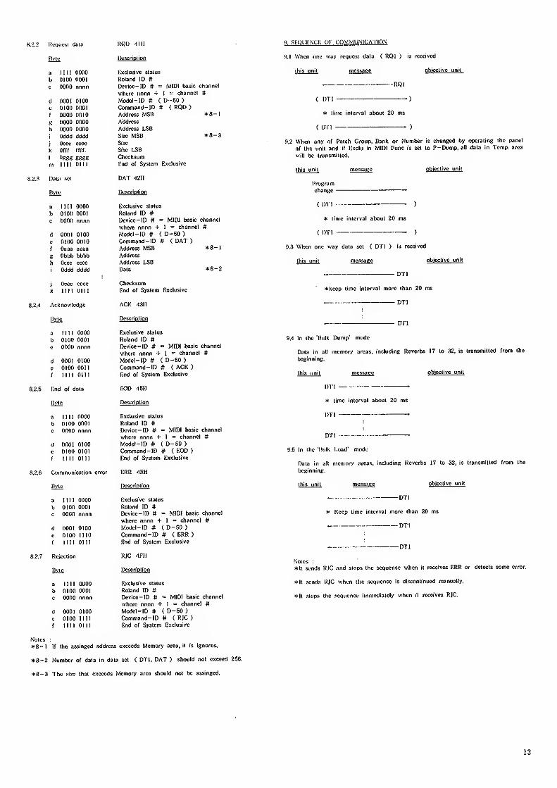
«,2.2 liwiufst duia ROD -1111
is
a 1111 0000 Exclusive status
b 0100 0001 Roland ID #c 0000 nnnn Dcvice-ID # = MIDI basic channel
where nnnn + I =- channel #(1 0001 01 OO MtxJcl- lD fl < D -50 )
c 0100 0001 Command-ID # ( ROD )
i 0000 0010 Address MSB *8-l
K 0000 0000 Address
h 0000 0000 Address LSI)
r Oddd dcJdd Size MSB *8-3
i Ocot' cccc S\7X
y. Offf ffff. Sixc I^B
1 OSKS SSKK Checksum
ni iin out l;nd of System Exclusive
8.2.3 Daiii SCI
B.2A Acknowledge
Bvie
a Mil 0000
b OlOO 0001
c 0000 nnnn
d 0001 0100
e 0100 OOHf 1111 0111
8.2.5 I'.nd of data
Rvte
DA'l" A2l\
Bvje IX'scriolion
3 1111 0000 Exclusive status
b 0100 0001 Roland ID #c 0000 nnnn Dcvicc-ID # = MID! basic channel
where nnnn + 1 = channel #d 000! 0100 ,Vodcl-!D ft ( D-50 >
e 0100 0010 Command-ID # ( DAT )
f Oaaa aaaa Address MSB *8-I
g Obbb bbbb Address
h Occc cccc Address LSDi Oddd dddd Data *8-2
j Oece cccc Checksum
k 1111 0111 End of System Rxclusivc
ACK -1311
Description
Exclusive status
Roland ID ft
Dcvice-IO ft = MIDI baac channel
where nnnn -i- 1 = channel #Model-ID ft ( D-50 )
Command-ID # ( ACK )
End of System Exclusive
EOD -ISH
Description
a 1111 0000 Exclusive status
b 0100 0001 Roland ID ft
c 0000 nnnn Uevice-ID # = MIDI basic channel
where nnnn + 1 = channel #d 0003 0100 Model-ID # C D-50 )
e 0100 0101 Command-ID ft < EOD )
r 11 11 oni End of System Exclusive
Communication error ERR -lEH
pyte Dcsc riotion
a 1111 0000 Exclusive status
b 0100 0001 Roland ID #
c 0000 nnnn Device-ID # = MIDI basic channel
where nnnn + I = channel #d 0001 0100 Model-ID ft ( D-50 )
c 0100 1110 Command-ID ft ( ERR )
r nil 0111 End of System Exclusive
Rejection RJC -IFH
Byte l>oscrjption
a 111! 0000 Exclusive status
b 0100 0001 Roland ID ft
c 0000 nnnn Device-ID ft = MIDI basic channel
where nnnn + 1 = channel #d 0001 0100 Model-ID ft ( D-50 )
e 0100 nil Command-ID ft C RJC >
f 1111 0111 End of System Exclusive
Notes :
*8-l If the assinged address exceeds Memory area, it is ignores,
*8-2 Number of data in data set ( DTI. DAT ) should not exceed 256.
*8-3 The sine that exceeds Memory area should not be assingcd.
9. si-:oi,:i:.\ci-: or communication
9.1 U'tien one way request data ( RQl ) is received
ihis unit message ob'tcctive unit
RQl
{ DTI — •)
* time interval about 20 ms
C DTI )
9.2 When any of Patch Group, Bank or Number is changed by operating the panel
of the unit and if Exclu in MIDI Func is set to P-Dump, all data in Temp, area
will be iransmiited.
this unit objective unit
Programchange
< DTI -)
* lime interval about 20 ms
C DTI )
9.3 When one way data set < DTI ) is received
this unit message objective unit
DTI
*kcep time interval more than 20 ms
. DTI
DTI
9.4 In the 'Bulk Dump' mode
Data in all memory areas, including Reverbs 17 to 32, is transmitted from the
beginning.
this unit objective unit
DTI
* time interval about 20 ms
DTI
9.5 In the 'Bulk Load" mode
Data in all memory areas, including Reverbs 17 to 32, is transmitted from the
beginning.
this unit objective unit
-DTI
* Keep time interval more than 20 ms
„ DTI
_ DTI
Notes :
*Ii sends RJC and slops the sequence when it receives ERR or detects some error,
*ll sends RJC when the sequence is discontinued manually.
*!l slops the sequence immediately when it receives RJC.
13
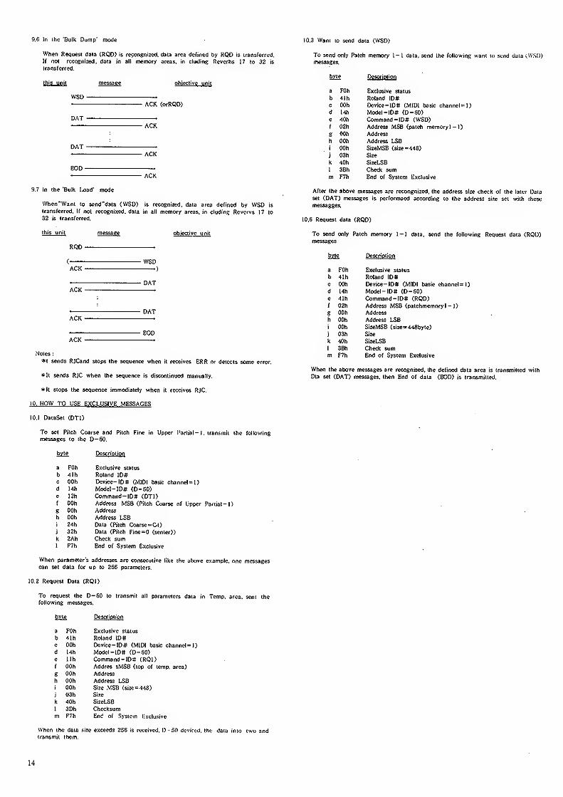
9.C In the 'Bulk Dump" mode 10.3 Want to send data (WSI»
When Request daia (ROD) is recongnized. data area defined by RQD is transferred.
If not recognized, data in all memory areas, in eluding Reverbs 17 to 32 is
transferred,
this unit message objective unit
WSD .
ACK (orRQD)
DAT .
• ACK
DAT .
ACK
EOD .
• ACK
9.7 In the "Bulk Load' mode
When"Wan[ to send-data (WSD) is recognized, data area defined by WSD is
transferred. If not recognixed, data in all memory areas, in eluding Rcvervs 17 to
33 IS transferred.
this unit message objective unit
RQD .
(• WSDACK .)
DATACK
DATACK .
EODACK .
Notes :
*t sends RJCand stops the sequerKc when it receives ERR or detects some error.
*It sends RJC when the sequence is discontinued manually.
*It slops the sequence immediately when it receives RJC.
10. HOW TO USE EXCLUSIVE MESSAGES
lO.l DaiaSet (DTI)
To set Pilch Coarse and Pilch Fine in Upper I'artial - 1 . transmit the following
messages to the D-50.
byle Descrioiion
a FOh Exclusive status
b 41h Roland 1D#c OOh Device-IDft (MIDI basic channel=l)d Mh Model-lDft (D-50)e I2h Command-ID# (DTI)f OOh Address MSB (Pilch Coarse of Upper
g OOh Address
h OOh Address LSBi 24h Data (Pitch Coarsc=CM)
j 32h Data (Pilch Fine=0 (scnler))
k 2Ah Check sum1 F7h End of System Exclusive
When parameter's addresses are consecutive like the alxjve example, one messagescan set data for up to 256 parameters.
10.2 Request Data (RQI)
To request the D-50 to transmit all parameters data in Temp. area, sent ihefollowing messages.
byle I>escription
a FOh Exclusive status
b -llh Roland iDff
c OOh Device-!D# (MIDI basic channel
d 14h Model ~ID# (D-50)e llh Command -IDif (RQI)f OOh Addres sMSB (lop of lemp. area)
« OOh Address
h OOh Address LSDi OOh Size .MSB {size='148)
j 03h Size
k 40h SizeLSB
1 3Dh Checksumm F7h End of System l^xclusive
When iho data size exceeds 256 is received. IJ - 50 deviced. the data into iwo andtransmit them.
To send only Patch memory 1 - 1 data, send the following want to send data (WSD)messages.
bvie Description
a FOh Exclusive status
b 4Ih Roland IDSc OOh i>evice~ID# (MIDI basic channel 1)
d 14h Model -ID# (D-50)e 40h Command-lD# (WSD)f 02h Address MSB (patch memoryl-1)S OOh Address
h OOh Address LSBi OOh SizeMSB (size=448)
j 03h Size
k 40h SizeLSB
1 3Bh Check summ F7h End of System Exclusive
After the above messages are recongnized, the address size check of the later Data
set (DAT) messages is performaed according to the address si^e set with these
messagges.
10.6 Request data (RQD)
To send only Patch memory l-I data, send the following Request data (RQD)messages
bjte Descriplion
a FOh Exclusive status
b 4Ih Roland IDSc OOh Deviee-ID# (MIDI basic channel=l)d 14h Model-ID# (D-50)e 41h Command-ID# (RQD)f 02h Address MSB (patchmemoryl- 1)
g OOh Address
h OOh Address LSBi OOh SizeMSB {size=448byte)
j 03h Size
k 40h SizeLSB
1 3Bh Check summ F7h End of System Exclusive
When the above messages are recognized, the defined data area is transmitted with
Dla set (DAT) messages, then End of data (EOD) is transmitted.
14
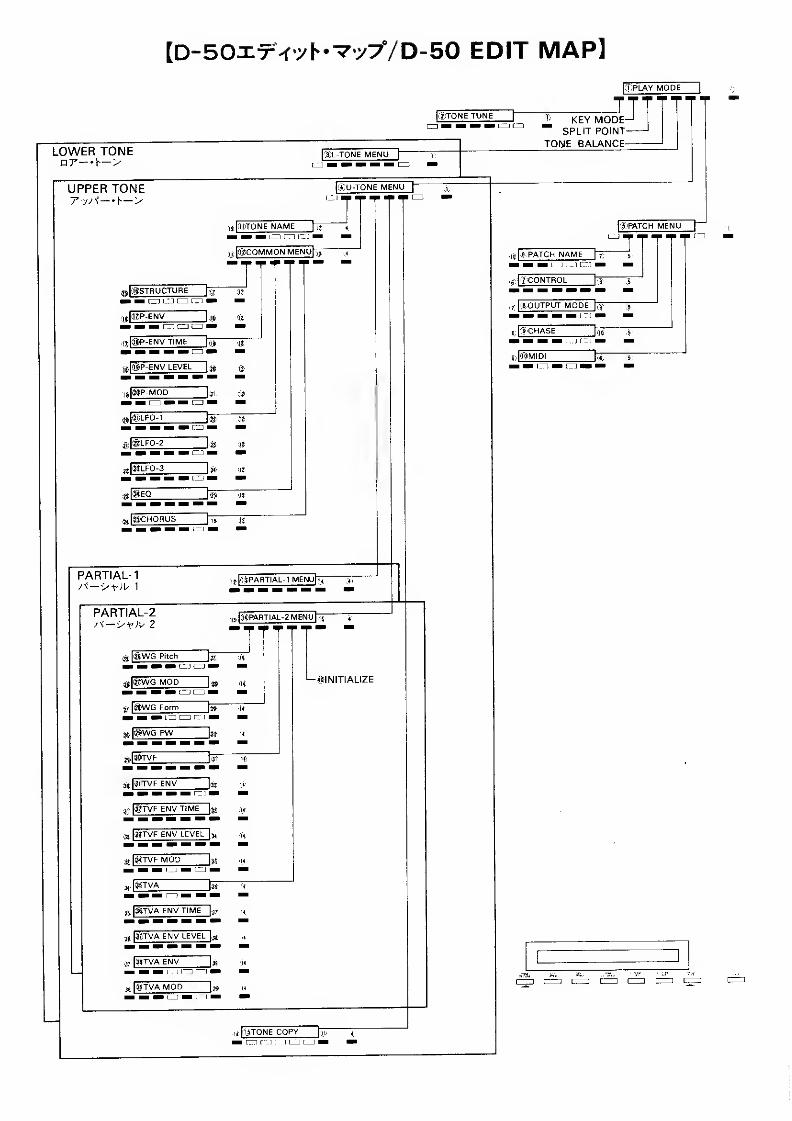
[D-BOxx-fyh-Vyy/D-SO EDIT MAP]•.DPLAY MODE
j(2JT0NE TUNE r
LOWER TONE [:3jL-T0NE MENU|
LU H H IB H CD
UPPER TONE
i^ lHTONE NAME]™ * m m
J
SU-TONE MENU
j@COMMONMENUpjr
j^|®STRUCTURE [jf
;|-t,|@P-ENV
I CD CZl C=t ™ii^|(aP-ENV TIME jjtT
iii|®P-ENV LEVEL Uj
,ii i®LFo-i mi-|;l®LF0-2
;t.|(g)LF0-3H an M
,^ |ij»CHOHijs"
PARTIAL-
1
,-i (.l^jPAflTIAL-l MENUfjT
PARTIAL-2i3,|(r'C'PARTIAL-2 MENU fir
a |@WG Pitch
'H
IIZD CZD ™ Vj)- |#WG Form
fj^ ^
T
3-t|®WG MOD! »
a.[
i^wG pw
atijiiTVF ENy
M |
j^^TVF ENVTIMEj^j
,3i|#TVF ENV LEVEL I3,
3t igTVF MOD
-^INITIALIZE
3-,, [jiTVA ENV TIME [ir
?"r,TVA ENV LEVEL |^
3STVA ENV
38 ii3jTVA MOD
it lliTONE COPY T™ n r" I : i [_J [ 1 ™
KEY MODE~ SPLIT POINT
TONE BALANCE
iSjPATCH MENU
|.6.PATCH NAME|
,6- ['"ZCONTROL
,r |(B.,OUTPUT MODE fj"
s;k?CHASE
a) #MIDII im riD I
1
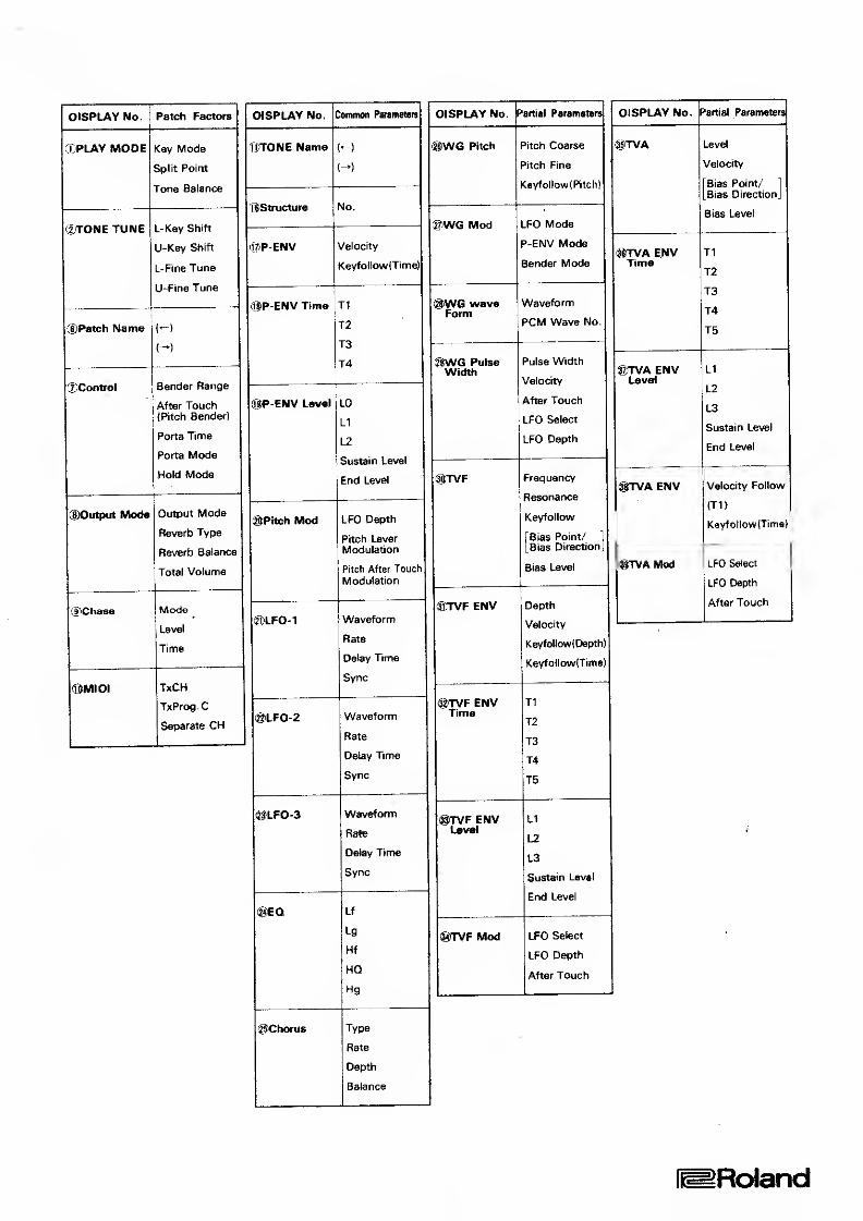
OrSPLAY No.
XPLAY MODE
rXTONE TUNE
®Patch Name
©Control
Patch Factors
Key Mode
Split Poim
Tone Balance
L-Key Shift
U~Key Shift
L-Fine Tune
U-Fine Tune
(Output Mode
®ChasB
Bender Range
After Touch(Pitch Bend^)
Porta Time
Porta Mode
Hold Mode
Output Mode
Reverb Type
Reverb Balanc
Total Volume
<!>MIDI
Mode
Level
Time
TxCH
TxProg.C
Separate CH
DISPLAY No. Common Parameters DISPLAY No. F'artial Parametere
QTONE Name ®WG Pitch Pitch Coarse
^'itch Fine
©Structure No.
l^WG Mod LFO Mode
P~ENV Mode
Bender Mode
!t?P-ENV Velocity
Kevfollow(Time)
®P-ENV Time Tl
T2
T3
T4
'^yNG waveForm
Waveform
PCM Wave No.
®VtfG PulseWidth
Pulse Width
Velocity
After Touch
LFO Select
LFO Depth
®P'ENV Level LO
L1
L2
Sustain Level
End Level ©TVF Frequency
Resonance
Keyfollow
[Bias Point/]
[Bias DirectionJ
Bias Level
®Pitch Mod LFO Depth
Pitch LeverModulation
Pitch After Touch
Modulation
®TVF ENV Depth
Velocity
Keyfo!low( Depth)
KeyfoHow(Time)
©LFO'-V Waveform
Rate
Delay Time
Sync
®TVF ENVTime
Tl
T2
T3
T4
T5
@LF0-2 Waveform
Rate
D^y Time
Sync
@LFO-3 Waveform
Hate
Delay Tirrte
Sync
@TVF ENVLevel
LI
L2
13
Sustain Level
End Level
ig)EQ Lf
Lg
Hf
HQ
Hg
®TVF Mod LFO Select
LFO Depth
After Touch
©Chorus Type
Rate
D^th
Batance
DISPLAY No. Partial Parameters
ENVTime
^)TVA ENVLevel
@TVA ENV
(giTVAMod
Level
Velocity
Bias Point/ 1
Bias DirectionJ
Bias Level
Tl
T2
T3
T4
T5
LI
L2
L3
Sustain Level
End Level
Velodty Follow
(T1(
KeyfollowlTime]
LFO Select
LFO Depth
After Touch
[^Roland
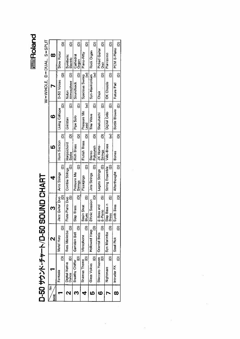
00
(/>UJ
(0
CO k-OO
3
^ o
11
<u —
to
(J
i- Qto
•a
o
cc
co >a, w
Sotoo.
a
Q-
W
s
to
CO
CM
3—Q
oco3 —aoc
C3
CO
CO
c «
m CD
CO
a
to
03 .™CDO.
I I
LU UJ
to
(0 E"
03
torn to
o9E
CO
a
00 in CO 00

D^Roland