Embed Size (px)
Citation preview

Disclosure to Promote the Right To Information
Whereas the Parliament of India has set out to provide a practical regime of right to information for citizens to secure access to information under the control of public authorities, in order to promote transparency and accountability in the working of every public authority, and whereas the attached publication of the Bureau of Indian Standards is of particular interest to the public, particularly disadvantaged communities and those engaged in the pursuit of education and knowledge, the attached public safety standard is made available to promote the timely dissemination of this information in an accurate manner to the public.
इंटरनेट मानक
“!ान $ एक न' भारत का +नम-ण”Satyanarayan Gangaram Pitroda
“Invent a New India Using Knowledge”
“प0रा1 को छोड न' 5 तरफ”Jawaharlal Nehru
“Step Out From the Old to the New”
“जान1 का अ+धकार, जी1 का अ+धकार”Mazdoor Kisan Shakti Sangathan
“The Right to Information, The Right to Live”
“!ान एक ऐसा खजाना > जो कभी च0राया नहB जा सकता है”Bhartṛhari—Nītiśatakam
“Knowledge is such a treasure which cannot be stolen”
“Invent a New India Using Knowledge”
है”ह”ह
IS 10398 (1982): Zener Barrier for Intrinsically SafeProcess Control Instruments [ETD 18: Industrial ProcessMeasurement and Control]


IS I 10398 - 1982.
Indian Standard SPECIFICATION FOR
ZENER BARRIER FOR INTRINSICALLY SAFE P~ROCESS CONTROL INSTRUMENTS
Industrial Process Measurement and Control Sectional Committee, ETDC 67
Chairman
PROF J. K. Crsonnmmy Jadavpur University, Calcutta
Members Representing
SHRI C. D. ANVDACHARI. FertiAizz;sl( Planning & Development )
SHRI K. P. SARMA ( Alternate ) SHRI R. S. ARORA Directorate General of Supplies &
New Delhi SERI K. R. BANERJEX Instrumentation Ltd, Kota
Skew K. SURYANARAYANA (Alternate) SHRI J. S. BHATIA Electronics Corporation of India Ltd, Hyderabad SERI J. K. CHATTERJEE Durgapur Steel Plant ( SAlL), Durgapur DR K. DAS GUPTA The Calcutta Electric Supply Corpn ( India ) Ltd,
Calcutta
India Ltd,
Disposals,
SHARI S. B. MUKHOPAD~YAY ( Alternate ) BRIG R. C. DHINCRA Directorate of Standardization, Ministry of
Dcfence, New Delhi SHRI M. K. KULYHRESHTA ( Alternate )
SHltl B. P. GHOSH National Test House, Calcutta SRRI D. N. UPADI~YAYA ( Alternate )
SHILI D. P. GO&L Central Scientific Instruments Organization, Chandigarh
SRRI A. N. AQARWAL ( Alternate ) SHRI R. K. GOI,IYA Udeyraj & Sons, Bombay
SARI P. C. GOLIYA ( Alttrnatc ) SHRI R. GOPALAKRIJH~AN Engineers India Ltd, New Delhi
SHRI A. K. V~RS~A ( Alternate ) SRRI K. V. GOPALRATNAM Institute of Design of Electrical Measuring
Instruments, Bombay SHRI P. K. VISWANATHAN ( Alternate )
( Continued on pugs 2 )
0 Cqyright 1983 INDIAN STANDARDS INSTITUTION
This publication b protected under the Indian Copyright Act ( XIV of 1957 ) and reproduction in whole or in part by any means except with written permission of the publisher shall be deemed to be an infringement of copyright under the said Act.

IS:10398 - 1982
( Continued fmn page 1 )
Members Representing SHRI S. G. JOSHI Indian Petrochemicals Corporation Ltd, Vadodara
SHRI T. S. NAGARAJAN (Altcrnatc ) SHRI S. MUEHEIZJEE SHRI B. c. N_UR
Institute of Paper Technology, Saharanpur MECON, Ranchi
SHRI G. BALASUBBAMANIUY ( Altcrnata ) SERI C. B. PANDIT
SHRI C. K. CHIJ~OTI ( Alternate ) Century Rayon, Kalyan
SHRI B. S. PRABHARAR Department of Atomic Energy, Bombay SI~RI S. RAMAKIUSHNAN ( Alternate)
SHRI D. S. V. RAJU SHRI G. N. MURTHY ( Altcrnatr )
ELICO Pvt Ltd, Hyderabad
SHRI N. N. SARKAR M. N. Dastur & Co Pvt Ltd, Calcutta Snar S. C. BOSE ( Alternate )
SHRI R. D. SHaRnrA SHRI T. K. ZUTSHI (Alternate)
Taylor Instruments Co ( India ) Ltd, Faridabad
SARI R. S~UNDHIKARAJAN Directorate General of Technical Development, New Delhi
Sam N. R. SRINIVASAN SIIRI S. P. MATHURE ( Alternate)
Indian 003rporation Ltd, New Delhi
SRRI S. P. SIJRI DR A. F. CHHAPGAR ( Altcrnatc )
National Physical Laboratory New Delhi
Sam M. G. TOSHNIWAL Toshniwal Industries Pvt Ltd, Ajmer SHRI SX. MAHESHWARI ( Alternate )
SHRI VINAY TOVHNIWAL SXRI V. V. VAIDYA
Toshniwal Brothers Pvt Ltd, Bombay Siemens India Ltd, Bombay
SHRI M. M. LOHIA ( Alternate ) Sam G. S. VARADAN Electronics Commission ( IPAG ), New Delhi
Da V. P. BHATRAR ( Altcrnatc) SHRI K. M. VENKATESAN Mahindra & Mahindra Ltd, 24 Parganar
SHRI AIZUN MAHINDRA ( Altcrnatc ) STIRI H. C. VEKMA Associated Instruments Manufacturers Pvt Ltd,
New Delhi SHRI M. D. NAIR ( Altcrnatc )
SRRI s. P. SACHDEV,
Director ( Elec tech ) Director General, IS1 (Ex-ojicio Member)
Secretary SRRI J. T. DAVIDSON
Assistant Director ( Elec tech ), ISI
IS : 10398 - 1982
Indian Standard SPECIFICATION FOR
ZENER BARRIER FOR INTRINSICALLY SAFE PROCESS CONTROL INSTRUMENTS
0. FOREWORD
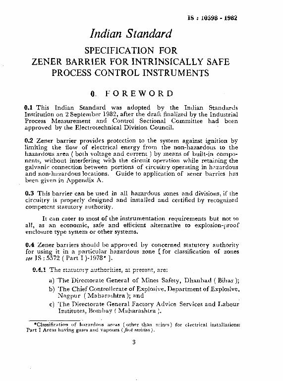
0.1 This Indian Standard was adopted by the Indian Standards Institution on 2 September 1982, after the ~draft finalized by the Industrial Process Measurement and Control Sectional Committee had been approved by the Electrotechnical Division Council.
0.2 Zener barrier provides protection to the system against ignition by limiting the flow of electrical energy from the non-hazardous to the hazardous area ( both voltage and current ) by means of built-in compo- nents, without interfering with the circuit operation while retaining the galvanic connection between portions of circuitry operating in hazardous and non-hazardous locations. Guide to application of zener barries hams been given in Appendix A.
0.3 This barrier can be used in all hazardous zones and divisions, if the circuitry is properly designed and installed and certified by recognized competent statutory authority.
It can cater to most of the instrumentation requirements but not to all, as an economic, safe and efficient alternative to explosion-proof enclosure type system or other systems.
0.4 Zener barriers should be approved by concerned statutory authority for using it in a particular hazardous zone [for classification of zones see IS : 5572 ( Part I )-1978* 1.
0.4.1 The statutory authorities, at present, are:
a) ~The Directorate General of Mines Safety, Dhanbad ( Bihar);
b) The Chief Controllerate of Explosive, Department of Explosive, Nagpur ( Maharashtra ); and
c) The Directorate General Factory Advice Services and Labour Institutes, Bombay ( Maharashtra ).
*Classification of hazardous arcas ( other than mines) for electrical installations: Part I Areas having gases and vapours ( jrst rcvi.sion ) .
3
IS : 10398 - 1982
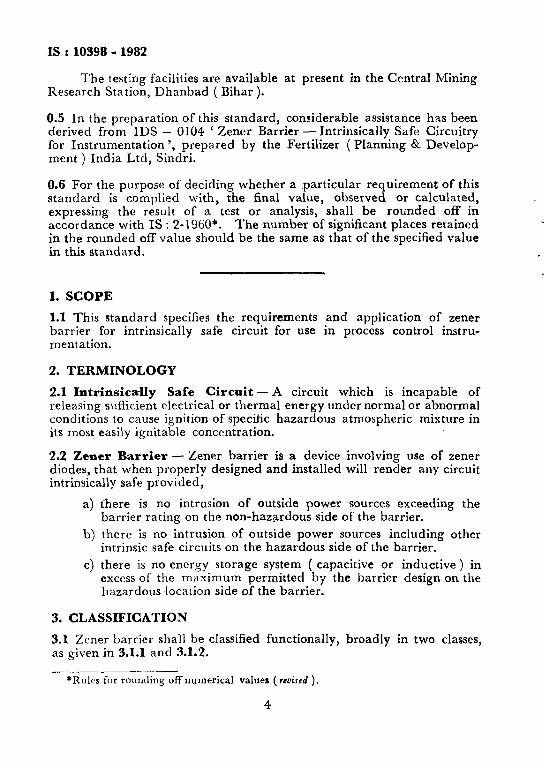
The testing facilities are available at present in Research Station, Dhanbad ( Bihar ).
the Central Mining
0.5 In the preparation of this standard, considerable assistance has been derived from IDS - 0104 ‘ Zener Barrier - Intrinsically Safe Circuitry for Instrumentation ‘, prepared by the Fertilizer ( Planning & Develop- ment ) India Ltd, Sindri.
0.6 For the purpose of deciding whether a particular requirement of this standard is complied with, the final value, observed or calculated, expressing the result of a test or analysis, shall be rounded off in accordance with IS : 2-1960*. The number of significant places retained in the rounded off value should be the same as that of the specified value in this standard.
1. SCOPE
1.1 This standard specifies the requirements and application of zener barrier for intrinsically safe circuit for use in process control instru- mentation.
2. TERMINOLOGY
2.1 Intrinsica-lly Safe Circuit - A circuit which is incapable of releasing sufficient electrical or thermal energy under normal or abnormal conditions to cause ignition of specific hazardous atmospheric mixture in its most easily ignitable concentration.
2.2 Zencr Barrier - Zener barrier is a device involving use of zener diodes, that when properly designed and installed will render any circuit intrinsically safe provided,
a) there is no intrusion of outside power sources exceeding the barrier rating on the non-hazardous side of the barrier.
b) there is no intrusion of outside power sources including other intrinsic safe circuits on the hazardous side of the barrier.
c) there is no energy storage system ( capacitive or inductive ) in excess of the maximum permitted by the barrier design on the hazardous location side of the barrier.
3. CLASSIFICATION
3.1 Zener barrier shall be classified functionally, broadly in two classes, as given in 3.1.1 and 3.1.2.
*Rules for rounding off numerical valuer ( rrviscd ).
4

IS : 10398 - 1982
3.1.1 Signal Transmission Barriers :
a) With common earth terminal, and
b) Earth free transmission circuits.
NOTE - Since some signals can have current strength as high as 120 mA in switching units, indicating units, and servo appliances, the barrier used in such places may be treated as special types.
3.1.2 Barrier Relays ( Intrinsically Safe Amplijcation Relays ) - The control circuit is complete with proximity switches, mechanical contacts, etc. By the use of these relays, non-explosion proof switches such as temperature switches, flow switches, level switches, etc, may be used in hazardous areas. However the barrier relays consisting ofpower supply, transistor/ semiconductor switching unit and an output relay shall be located in non- hazardous area.
The use of barrier relays in power supply units in safe area for intrinsically safe transmitters mounted in the unsafe area is shown in Fig. 1
NON- HAZARDOUS AREA
BARRIER TERMINATION
TRANSMITTER
I
I RECORDER I I I
FIG. 1 USE OF BARRIER RELAYS IN POWER SUPPLY UNITS IN SAFE AREA FOR INTRINSICALLY SAFE TRANSMITTERS MOUNTED
IN THE UNSAFE AREA
4. DESIGN REQUIREMENT
4.1 Voltage-The voltages on the non-hazardous and hazardous locations at the barrier shall be as given below:
a) On the non-hazardous location of the barrier, the maximum operating voltage shall be limited to 250 V ac rms; and
5

.
IS : 10398 - 1982
b) On the hazardous location of barrier, the voltage shall be limited to a maximum value of f50 V or -50 V depending on the use of positive or negative barrier, subject to condition that energy transfer is below the ignition level. The recommended voltages for standardization a.re + lOV, +ZOV, +3OV, - lOV, -2OV and -30V ( other voltages may be considered as special/optional ).
4.2 Current - The maximum permissible short circuit current shall be limited to 150 mA subject to condition that maximum short circuit power transfer is below the ignition level of the hazardous gases under reference ( short circuit power generally less than 1 320 mW ). The current flowing to hazardous areas shall be resistive only.
4.3 Temperature - The temperature within barrier enclosure shall not exceed 55°C.
4.4 Load - Field equipment used shall be resistive only. If otherwise, these shall be made resistive by adding a redundant diode in parallel with inductance components or preventing capacitance discharge to field wiring by use of resistors and series diodes.
4.5 Casing -Barriers shall be encapsulated in epoxy resin or into plastic polyestor or other suitable resin.
5.
5.1
MOUNTING
Barriers may be mounted in one of the following locations:
a) In non-hazardous locations in dust and splash-proof enclosures or in control rooms close to the hazardous areas;
b) In hazardous locations, if mounted in explosion-proof housings certified suitabb for that area; and
c) In purged/pressurized cabinets/housings.
5.2 Type of Mounting - The barriers shall be mounted on separate copper railings or bus bar of 35 mm width x 3 mm thickness ( minimum width 25 mm ) either with snap fixings or with two mounting studs ( see Fig. 2 ). The potential equalizing nut, bus-bar mounting pillars ( generally locking plates, railings, fixtures, etc, whichever are applicable ) shall be preferably procured from the manufactures. The barriers shall not be housed together with ather non-intrinsic safe items or explosion- proof equipment or intrinsic safe equipment of other manufacturers and certified for different area classification.
6. EARTHING
6.1 Earthing is very important for the proper functioning of the barrier for intrinsic safe circuitry.
6

IS : 10398 - 1982
INTEGRAL CONDITIO’NING REslsToR (OPTIONAL 1
SAFE AREA CONNECTION (SUPPLY 1
FIG. 2 MOUNTING STUDS ( EARTHED ) DOUBLE STUDS TO ENSURE BETTER EARTHIHG
The signal earth system shall consist of conductors separate from the power earthing system.
The earthing conductor shall be connected to the signal earth reference point which is a single earthing point which may be used as a earth reference for more than one intrinsicsafe system.
6.2 The maximum resistance allowable between the farthest point in the intrinsic safe barrier earth bus and the signal bus reference point shall not exceed 1 ohm. All metallic enclosures for the intrinsic safe circuit shall be bonded to the signal earth reference point through a metallic path.
7. WIRING REQUIREMENTS
\
7.1 The cable used shall be twisted ~pair type of copper conductor, preferably with screening.
1 7.2 The conductor insulation thickness shall not be less than 0.25 mm.
7.3 The cables used for either connecting equipment located in hazardous area and barrier and rela.ted safe area equipment shall be distinctly colour coded -with bright blue overall PVC sheath. This colour shall not be used for other wiring.
7.4 Cables employed for intrinsic safe circuit connections shall not be mixed up with cables used for connecting explosion proof equipment for connecting intrinsic safe circuits of other makes, and non-intrinsic safe
7
IS:10398- 1982
wiring both in field and control room areas on both sides of terminals ( safe and intrinsic safe sides). These shall be run in separate trays/ ducts/raceways connected through separate junction boxes. These shall be distinguished with separate and distinct colour coding/painting that is preferably bright blue.
7.5 Different intrinsic safe circuits shall not be connected through a common multicore conductor cable.
7.6 In field/hazardous areas, the conductor used for earthing are preferably insulated type and the insulation shall be removed at the actual point of termination or common earth.
7.7 Earthing conductor employed for intrinsic safe circuits shall not be looped to earthing conductors of non-intrinsic safe circuits/explosion proof circuits. They shall be run separately and connected to the final earth directly.
7.9 The values of inductance and capacitance of wiring shall be as per manufacturer’s recommended values, and shall not exceed 3 mH and 0.1 PF respectively.
7.9 In enclosures containing different intrinsic safe circuits, terminals shall be of barrier type that is with physical partitions between terminals. Terminals may be separated by insulated or grounded metal partitions.
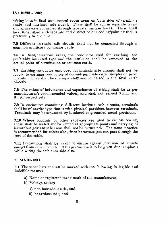
7.10 Where conduits or other raceways are used to enclose wiring, these shall be sealed and/or vented at appropriate points and carrying of hazardous gases to safe areas shall not be permitted. The same practice is recommended for cables also, since hazardous gascan pass through the core of the cable.
7.11 Precautions shall be taken to ensure against intrusion of unsafe energy from other circuits. This precaution is to be given due emphasis while wiring the safe area side also.
8. MARKING
8.1 The zener barrier shall be marked with the following in legible and indelible manner:
a) Name or registered trade-mark of the manufacturer;
b) Voltage rating:
i) non-hazardous side, and
ii) hazardous side; and
8

IS : I0398 - I982
c) Information to the fact that zener barrier has been approved by the concerned statutory authority.
9. TESTS
9.1 The zener barrier shall be examined and tested in accordance with the requirements specified herein.
9.2 The barrier shall be examined for agreement with the information contained in the manufacturers drawings, including values and ratings of components and shall be in accordance therewith.
APPENDIX A
( Clause 0.2 )
APPLICATION OF ZENER BARRIER
A-l. The barrier shall ensure by virtue of the design of the circuit, that the energy transmitted to the hazardous location is restricted to a level insufficient to cause ignition both during normal and abnormal (fault condition) operations of the instruments installed both in the hazardous and non-hazardous locations. The barrier shall serve only as a terminal for electrical connection between hazardous and non-hazardous locations.
The barriers are bipolar in nature and hence can be used both for positive and negative voltage circuits.
A-2. The typical uses of barriers are as shown in Fig. 3.
9

IS:10398-1982
HAZARDOUS AREA SAFE AREA
- ____
!I
EARTH FREE
SIGNAL
\ I -- ___
INSULATED FROM
i EARTH --
ic I kMAY BE &
EARTHED
( C.OMPENSAllNG CABLE --J
II 2 Channet Batrtor
PROTECTION OF THERMOCOUPLE CIRCUITS
HAZARDOUS AREA SAFE AREA
c
OE
al Floalmg Power Supply
PROTECTION OF 2-WIRE TRANSMITTER CIRCUITS .
FOG. 3 TYPICAL USES OF BARRIERS -~ Con/d
10

Is : 10398 - 1982
HAZARDOUS AREA I
SAFE ARC A
Q 1 %Wlre. One Wire Earthed
bl L-Wire
PROTECTION OF RESISTANCE THERMAL DETECTOR CIRCUITS
HAZARCIOUS
al Shunt-Diode Borr~or and Relay
PROTECTION OF CONTROL AND LIMIT-SWITCH ClR&lTS .
FIG. 3 TYPICAL USES OF BARRIERS
11
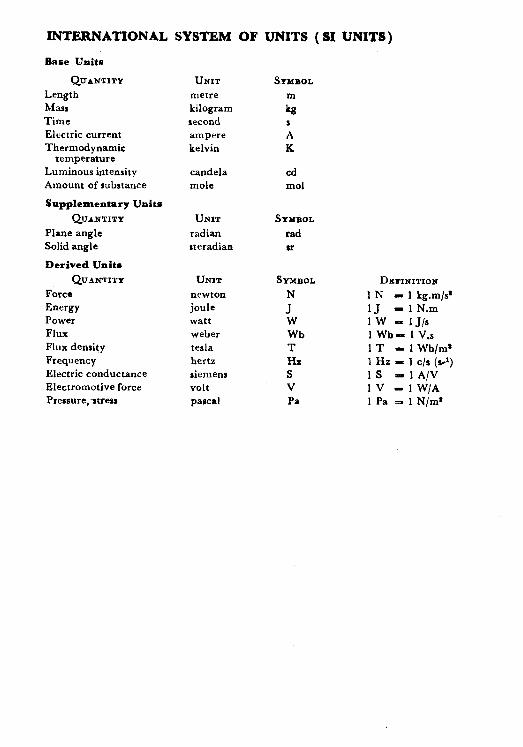
INTERNATIONAL SYSTEM OF UNITS ( SI UNITS-)
Base Units
QUANTITY
Length Marl Time Electric current Thermodynamic
temperature Luminous intensity Amount of substance
Supplementary Units
QUANTlTY
Plane angle Solid angle
Derived Units
QUANTITY
Force Energy Power Flux Flux density Frequency Electric conductance Electromotive force Pressure,stress
UNIT
metre kilogram second ampere kelvin
candela mole
UNIT
radian steradian
UNIT
newton joule watt weber terla hertz aiemens volt pascnl
SYMBOL
m
kg s A K
cd mol
SYMBOL
Tad
sr
h%BOL
J" w
Wb T Ha S V Pa
DEFINITIOIP
1 N - 1 kg.m/ss 1J - 1 N.m 1W -IJ/s 1 Wb- 1V.s 1T - 1 Wb/m* 1 Hz - 1 c/r (s-1) IS = 1 A/V 1v - 1 W/A 1 Pa = 1 N/m’