Embed Size (px)
Citation preview

Disclosure to Promote the Right To Information
Whereas the Parliament of India has set out to provide a practical regime of right to information for citizens to secure access to information under the control of public authorities, in order to promote transparency and accountability in the working of every public authority, and whereas the attached publication of the Bureau of Indian Standards is of particular interest to the public, particularly disadvantaged communities and those engaged in the pursuit of education and knowledge, the attached public safety standard is made available to promote the timely dissemination of this information in an accurate manner to the public.
इंटरनेट मानक
“!ान $ एक न' भारत का +नम-ण”Satyanarayan Gangaram Pitroda
“Invent a New India Using Knowledge”
“प0रा1 को छोड न' 5 तरफ”Jawaharlal Nehru
“Step Out From the Old to the New”
“जान1 का अ+धकार, जी1 का अ+धकार”Mazdoor Kisan Shakti Sangathan
“The Right to Information, The Right to Live”
“!ान एक ऐसा खजाना > जो कभी च0राया नहB जा सकता है”Bhartṛhari—Nītiśatakam
“Knowledge is such a treasure which cannot be stolen”
“Invent a New India Using Knowledge”
है”ह”ह
IS 4682-5 (1970): Code of practice for lining of vesselsand equipment for chemical processes, Part 5: Epoxide resinlining [MED 17: Chemical Engineering Plants and RelatedEquipment]


IS : 4682 ( Part V ) - 1970
Indian Standard
CODE OF PRACTICE FOR LINING OF VESSELS -AND EQUIPMENT FOR
CHEMICAL PROCESSES
PART V EPOXIDE RESIN LINING
( Fourth Reprint OCTOBER I993 )
UDC 66.023.3:621.642.:678.643
@ Cop)viglrt 1971
BUREAU OF INDIAN STANDARDS MAh’AK BHAVAN, 9 BAHADUR SHAH 7AFAR MARG
NEW DELHI 1102
Gr 5 August 197 1
IS : 4682 ( Part V ) - 1970
Indian Standard
CODE OF PRACTICE FOR LINING OF VESSELS AND EQUIPMENT FOR
CHEMICAL PROCESSES
PART V EPOXIDE RESIN LINING
Chemical Engineering Sectional Committee, EDC 57
Chairman
UN 0. P. KHARBANDA
Members
SART S. S. RAO ( Altcrnalc to Dr 0. P. Kharbanda )
SHRl A. K. BASU PROF G. S. R. NARASIMAHA-
MURTY ( Alk-rnak ) SHRI S. D. BBARIN
SHRI S. SEN GUPTA ( Altnnnte)
SARI A. B. MALLIK ( Ahmute 1 SHRI P. K. CHAKRAVART’Y
SRHI A. K. BOSE
.
Directorate General of Technical Development, New
Imperial Chemical Industries (India ) Private Ltd,
Delhi
Calcutta
Direc;erh; General of Supplies- & Disposals, New
Fertilizer Association of India, New Delhi Indian Oil Corporation Ltd ( Refineries Division ),
New Delhi
Larsen & Toubro Ltd, Bombay
Indian Institute of Chemical Engineers, Calcutta
I)R K. S. CHARI SHKI C. R. DASQUF~A
SHRI K. C. JAIN ( Alrem& ) DR L. K. DORAIBWAMY
SHRI R. S. GRAVER Sam B. D. MELLO ( Al&mate )
SHRI J. P. Joam PIIOF N. R. KAMATE
SHHI K. A. NAIB ( Ahmat ) SHIU J. 6’. KAPUR
DR R. K. GUPT~ ( Altemutc ) DIG M. G. KRWRNA
SHRI T. S. NAYAR ( AltmnaU) SHRI K. MANIVANAN
Council of Scientific and Industrial Research, New Delhi
The Ralph M. Parsons Co of Asia, Bombay
Walchandnagar Industries Ltd, Bombay Indian Institute of Technology, Bombay
Indian Chemical Manufacturers Association, Calcutta
Indian Institute of Petroleum ( CSIR ), Dehra Dun
Directorate of Industries, Government of Haryana, Chandigarh
( Continued on pp 2 )
BUREAU OF INDIAN STANDARDS h{ANAic BHAVAN, 9 BAHADUR SHAH ZAFAR MARG
NEW DELHI 110002

IS : 4682 ( Part V ) - 1970
( Contiflucd jiom page 1 )
Members
SARI B. B. MATHUR SBRI I. B. LAL ( Afternute)
SHRI R. C. MISRA SHRI K. C. MOHAN
Representing
The Delhi Cloth & General Mills Co Ltd, Delhi
Heavy Electricals ( India ) Ltd, Bhopal Hindustan Steel Ltd. Ranchi
SHRI C. N. KHASTAOIR ( Alternate )
SHIU p. x. -PAI Esso Standard Refining Co of India Ltd, Bombay SHR~ 8. S. R. ANJANP ‘T:LW ( Ahrnate )
SIIRI R. PRABHAKAR Tata Chemicals I.td, Mithapur &RI A. P. RAO Sharat Heavy Plate and Vessels Ltd, New Delhi
SIKRI M. VENKATARATNAM ( Alternate ) SIIR~ D. G. RAO The Fertilizer Corporation of India Ltd, New Delhi
SHRI A. DIJTTA MAZUMDAII ( Alternate ) SIIRI H. S. RAO Lloyd’s’Register of Shipping, Bombav
Su1.1 J. N. Goxwi. .‘-< .?fternda ) SIXR~ V. M. nao The K. C. P. Ltd. Madras
SHRT K. SATYAN.~I: +. > or 4 ( Alternote ) SHIU R. SAI)AOOPA CHAR.: Burmah-Shrll Refineries Ltd. Bombay
SHRI S. L. ARANHA ( Jiternate) Sum D. S. SAETRY Hindustan Organic Chemicals Ltd, Bombay
SHRI 0. P. DANI ( Al:-rwte ) DRV. C. THAKAR ’ ’ Associated Cement Companies Ltd, Bombay
SRRI A. K. MISSER ( Alternate) SHRI N. THANDAVAN The A. P. V. Engineering Co Private Ltd, Calcutta
SHRI J. G. BROWN ( Alternate ) DR Y. VENRATESUAM National Research Development Corporation of
India, New Delhi DR D. S. VISWAXATH Indian Institute of Science, Bangalore
DH P. K. DESPANDR ( Alternate ) SHRI M. V. PATANICAR, Director General, ISI ( Er-&cio Member)
Director ( Mech Engg i
Bcre tary
SHNI M. G. Krtrsm~lv RAO
I kuur-!* Director ( Mech Engg ), 1st
Process Vessels Subcommittee, E1.X 57 : 2
Convener
Sam N. TUANDAVAN The A. P. V. Engineering Co Private Ltd, Calcutta
Members
DR ASGHAR HUSAIN Regional Research Laboratory ( CSIR ), Hyderabad SHRI K. SESHACHAHYULU ( Alternate )
~SH~I J. M. AYAN DUTTA DK D C. TAPADAR ( Alternatc )
Indian Institute of Chemical Engineers, Calcutta
SRRI A. R, B,na.\a Esso Standard Refining Co of India Ltd, Bombay SERI N. K. Buzar q National Chemical Laboratory ( CSIR ), Poona San1 S. GHoSn Imperial Chemical Industries ( India ) Private Ltd,
Calcutta Da S. K. Canx~a ( Alternate )
( Conlinued on paps 19 )
L
2

IS : 4682 ( Part V ) - 1970
Indian Standard CODE OF PRACTICE FOR
LINING OFF VESSELS AND EQUIPMENT FOR CHEMICAL PROCESSES
PART V EPOXIDE RESIN LINING
0. FOREWORD
0.1 This Indian Standard ( Part V) was adopted by the Indian Standards Institution on 23 December 1970, after the draft finalized by the Chemicai Engineering Sectional Committee had been approved by the Mechanical Engineering Division Council.
0.2 This standard is being issued in many parts; the epoxide resin linings of vessels and equipment is covered in this part, the other types of linings are covered in the remaining parts of this standard.
0.3 The use of linings of polymeric materials as a ~protection against corrosion has been the normal industrial practice for nearly half a century. A bond is developed between the applied lining and the metal and any attempt’to pull them apart will normally result in the lining tearing before the bond yields. Thus the lined vessel is suitable for use both for pressure conditions as well as vacuum conditions. While it is normal to use lined metallic vessels, non-metallic surfaces like wood and concrete are also often lined.
0.4 To enable the lining contractor to decide on a suitable lining, it is necessary that he has full information of the duties to which the lined vessels will be subjected. The information to be exchanged between the contractor and the user is given in Appendix A for guidance.
0.5 In the preparation of this standard, assistance has been derived from BS CP 3003 : Part 5 : 1966 ‘ Lining of vessels and equipment for chemical processes, Part 5 Epoxide resins ‘, issued by the British Standards Institution.
0.6 For the purpose of deciding whether a particular requirement of this
standard is complied with, the final value, observed or calculated, expres- sing the result of a test, shall be rounded off in accordance with IS: Z-1960*. The number of significant places retained in the rounded off value should be the same as that of the specified value in this standard.
*Rules for rounding off numerical values ( revised).
3
c

IS:4682 (Part V) - 1970
1. SCOPE
1.1 This standard (Part V ) lays down. the recommendations for lining of vessels and equipment lined with stoved lining, polyamide-cured lining, epoxide coal-tar lining, high solids lining, epoxide resin based lining and amine cured lining; and also design, application, maintenance, inspection and testing together with recommendations for design of equipment to be lined.
2. TERMINOLOGY
2.0 For the purpose of this standard, the following definitions shall apply. 2.1 Bpoxide-Resin-Based Linings -Linings based on resins usually formed by the reaction of epichlorophydrin and diphenylol propane. They are usually applied as a formulation containing solvents or pigments or both, to which curing agents are added.
2.2 Amine-Cured Linings - Polymine-cured epoxide resin linings and polymine adduct cured epoxide resin linings.
3: MATERIALS
3.1 General - Epoxide resin based linings are used for protecting equip- ment against chemical attack. They are used also ~for the prevention 01 contamination of various products by minute quantities of compounds which may be formed in case of direct contact with metallic equipment.
3.1.1 These linings can also be used to prevent the deposition of solids on the walls of the equipment involved and to facilitate cleaning.
3.1.2 Unless the lining is known from previous experience to be suitable, test panels should be exposed to conditions similar to those of service for not less than three months or preferably longer. The panels should be examined carefully for any signs of failure before instructions for application of the lining are given.
3.2 Grades and Properties
3.2.1 Amine-Cured and Stoued Linings - Amine-cured linings cure at room temperature under the action of a curing agent added before application. and can be applied on site. This has the advantage that the vessel& involved need not Abe sent to special lining firms.
3.2.1.1 Epoxide resin stoved linings are applied as single pack coatings and usually consist of epoxide and phenolic resins which are cured by stoving. They are generally more temperature resistant than amine-cured linings and their chemical resistance is generally better. These stovec
L
4

IS : 4682 ( Part V ) - 1970
linillgs shotlId be cured at the correct temperature as specified by the supplier; this will normally be in the range of 150 to 200°C. They are (ised preferably for equipment which can he transported and stored. Heat curin? in sits is possible, but the vessel involved should be insulated very cat~c~l’ully to prevent loss of heat.
3.2.1.2 ‘l’he various properties of these coatings are dealt with below. It should be noted that where pigments are used, they should be resistant to any corrosive substance likely to be encountered. In ail cases, it is assumed that a sufficiently thick and pin-hole free lining has been applied.
a)
b)
C 1’ 4 e)
.- L‘)
3
3.2.2
Resistance to acids-These linings resist most acids except those of 1 strongly oxidizing nature. *Nevertheless, possible imperfections Ln the lining caused by application difficulties or mechanical damage render them unsuitable if rapid attack of the base material would occur through direct contact with the acids.
Resistance to alkalis-They have excellent resistance to alkaline solutions.
Resistance to chlorine and hypochlorites- They offer a limited resistance to dry chlorine. They are destroyed by wet chlorine as well as by solutions of hypochlorite.
Resistance to salts - They are generally resistant to neutral salts.
Resistance to organic solvents -They are resistant to a wide range of solvents; they should not be used in the presence of ketones, most chlorinated hydrocarbons or phenols.
EJkt of temperature-The effect of temperature on these linings varies with each particular formulation. Normally, amine-cured tinings may be used at temperatures up to 90°C under dry conditions or up to 70°C under wet conditions; for stoved linings, the corresponding temperatures are 120°C and 80°C respectively.
Effect on heat franrfer rates- transfer rates is negligible.
The effect of these linings on heat
Resistance to erosion -These linings, being touch and glossy, offer good resistance to erosion by suspended particles.
Resistance to surface deposit forma.tion - They have good resistance to the build-up of deposits.
Polyamide-Cured Linings, Epoxide Coal-Tar Linings and High Solids . . . _ . . . . Linings-Besides polyamine and polyamme adducts, polyamides may be used for curing epoxide resin based linings at room temperature. The resistance to chemicals obtained differs from that of amine-cured linings,
5

IS : 4682 (Part V )- 1970
in that the water resistance is improved and the resistance to alkali and solvents is lowered. These materials are not generally used for lining vessels and equipment for chemical processes, being more suitable for exterior paint work under certain conditions. Where resistance to water is specially required, epoxide coal-tar linings are preferred.
3.2.2.1 Epoxide coal-tar linings consist of a combination of epoxide resin and coal-tar pitch, solvents, inert fillers, or pigments or both and a suitable curing agent. such was nolvamines. nolvamine adduct and nolva- mides.
a)
b)
The use of this type of’lining has two advantages: A 1
The layer thickness of 0.15 mm to 020 mm of this lining may be obtained in one coat which is far more than can be obtained in one coat when using amine cured or stoved linings.
The resistance to water is better than that of amine-cured or even polyamide-cured linings. L’k 1 e many organic materials the resis- tance to demineralized water is limited at high temperatures.
3.2.2.2 Another type of epoxide resin based lining which may be applied in thick layers is the SO called high solids lining. It contains only a very small quantity of, the solvent; this simplifies the pr~+lem of exhaus- ting fumes. pigments and
In extreme cases, a h_igh solids lining consists only of resin, fillers to which a curmg agent is added just before or during
application. Layers of 0.25 mm may be obtained in one coat. The chemical resistance is comparable with that of amine-cured linings, but the resistance to water is better.
4. DESIGN OF VESSELS AND EQUIPMENT
4.1 General
4.1.1 Interior Surfacis and Fittings - The surfaces which are to be covered with epoxide shall be easily accessible and free from pitting or other physi- cal imperfections. Interior fitt.ings should be designed to allow safe and easy movement of the operator or, if this is not possible, a manhole should be provided in each section of the vessel being lined.
4.1.2 Access to Vessel and Ventilation -The design of all vessels and equip- ment shall allow for adequate access and venting of fumes evolved during the preparation of the surface and the application of the coating.
4.1.2.1 In completely enclosed vessels, there shall be at least one manhole conforming to IS : 3 133-1965* and one additional branch of not less than 75 mm bore. The method of ventilation shall be the subject of
agreement at the tendering stage between the lining contractor and the customer and shall ensure that m no case can pockets of stagnant vapour or gas occur.
*Specification for manhole and inspection openings for chemical equipment.
6

fS:WK2 (Part V)-1970
4.1.3 Clearances - Allowance should always be made for the thickness of the lining or covering in calculating clearances.
4.1.4 Branches and Outlets -All branches shall be flanged and the lining taken over the flange face to prevent the in_gress of liquors behind the linings.
4.1.5 Surface Contours- Sharp changes of,contour in the surface to be covered shall be avoided wherever possible and such ~changes shall be finished to suitable radius; in all cases this shall be such that the internal radius of the lining is not less than 4 mm or the thickness of the lining.
4.1.6 Heating- Any steam coil or immersion heater used for heating the contents of the vessel shall be situated not less than 100 mm away from the epoxide-lined -surface to avoid lo& overheating. When heating by steam injection, care shall be taken’to avoid direct impingement of steam on the epoxide surface.
4.2 Fabricated Mild Steel Vessels
4.2.1 Fabrication and Testing- Mild steel vessels should be fabricated and tested in accordance with recognized standards of good design and practice. Only welded or seamless construction shall be used. Riveted constructions are not recommended.
4.2.2 Vessels to be Provided with Staved Linings- Special precautions are necessary for fabricated mild steel vessels which are provided with stoved linings, so as to prevent the occurrence of lining failures during stoving. For this reason the recommendations in 4.2.3 and 4.2.4 should be followed.
4.2.3 Welded Joints-Welding shall be in .accordance with the require- ments of either IS : 823-1964*, IS : 132349667 or IS :2825-l!&& Lap joints should be avoided as far as possible. Butt welds in both butt joints and T-joints, shall be made with more than one run of the electrode or ~blowpipe. The weld shall be ground smooth and flush on the side to be covered. Welds shall be ~made from the side to be covered wherever possible. Where it is not possible to weld from the side to be covered, the root should be chipped out and a sealing run used as shown in Fig. 1.
4.2.3.1 Wherever possible, corner joints (see Fig. 2A ) shall be replaced by butt welded flanged plates (see Fig. 2B).
4.2.4 Surface Contours- External angles and the edges at the junction’ of plates shall be removed by the most convenient means and the surface ground smooth to the required radius (see Fig. 3 ). Where corner and T-joints are unavoidable, they shall be filled at welded and ground smooth and concave to the required .radius.
*Code of procedure for manual metal arc welding of mild steel. iCode of practice for oxy-acetylene welding for structural work in mild steel (revisrd~). $Code for unfired pressure vessels.
7

IS:4682 (Part V)-1970
WIDE ROOT SEAL RUN
Fxo. 1 SEALING RUN
FINISHED SMOOTH
LUNFINISHED CONTINUOUS WELD
FIG. 2A A TYPICAL CORNER JOINT
LINING Y m WELD
IN A WELDED BUTT JOINT
LFLANGEO PLATE
FIG. 2B BUTT-WELDED * FLANGED PLATE
4.2.5 Branches and Outlets -All branches and ~out1et.s shall be designed a flanged pipes to allow the epoxide lining to cover the flange face. Typica flanged joints are illustrated in Fig. 4. Where small bore branches arc necessary they shall be adequately stiffened with gussets.
4.2.5.1 Pads should be. avoided wherever possible, but are sometime! necessary in place of small bore branches to prevent damage during handling and erection. Fixing holes in pads shall not penetrate the she1 of the vessel ( see Fig. 5 ).
8

IS:4682 (Part V)-1970
LINING 7
EXT ‘ERNAL TO 1 BE RE
FE. 3 ROUNDING OF EXTERNAL ANGLES
4.2.6 Sectional Tanks-Mating flanges of sectional tanks should be square~and plumb, and sections should be made to avoid distortion when
, bolted together. Normally, soft gaskets should be interposed between lined flanges.
4.3. Cast Iron Vessels-Cast iron presents difficulty in lining due to porosity, mould marks, and the effect of grain size in the casting. These factors increase the possibility of air inclusion.
4.3.1 Castings shall be of close grained iron and shall be substantially free from cavities and porosity. If any of these defects aF#e& after casting they shall be left untreated. The remedying of any defects after short- blasting should be agreed between the supplier and the contractor. All surfaces shall be free from fins, sharp projections, etc.
4.3.2 In order to reduce the-possibility of surface blow-holes forming, it is preferable that the face to be covered is the lower one when the casting is made.
4;3.3 When very large, heavy or complex castings are to be lined, it is essential that the advice of the epoxide lining contractor be sought at an early stage.
4.4 Other Metal Vessels -The general construction details and princi- ples already given for mild steel vessels (see 4.2) also apply to vessels constructed of stainless steel, copper, aluminium and their alloys. In view of the softer nature of some of these metals it is recommended that the design should provide for maximum rigidity.
4.4.1 Full details of the metal should be* given to the lining contractor for confirmation that lining can be satisfactorily bonded.
9

IS : 4682 ( Part V ) - 1970
F SOFT GASKET
c f
GASKET TO BE 6mm CLEA4 OF RADIUS
SOFT GASKET
LINING --d i_EEaUAL TO THICKNESS
CF SHELL
4A
/
SPACER
/LINING SOFT GASKET f! LINING
4B 4C
FIG. 4 TYPICAL FLANGED JOINTS
c
10

IS : 4682 (Part V)-1970
LL lNSlDE WELDS FINISHED OUNO AND SMOOTH TO
Gmm MIN RAD
WELD FOR AIR VENTING
1:1c. 5 OUTLET PADS
4.5 Concrete Vessels
4.5.1 The concrete vessels to be lined should be so shaped that the lining can be taken over the edges and down the outside for not less than 75 mm. When vessels are line ‘as cast ‘, the lining contractor should be left to fill in the corner with suitable epoxide strip.. Screed finishes should be rounded to a radius of about 6 mm on all corners and edges.
4.5.2 The concrete surfaces should be reasonably smooth and free from surface imperfecrions and dust. This can be achieved by any one of the following methods :
a)
b)
4.5.3
By casting the concrete against specially smooth formwork and taking precautions to ensure that it is fully compacted and that no leakage of mortar takes place between the joints in the formwork. Any porosity in the surface should be made good with an approved filler such as epoxide mastics. The use of parting agents on shuttering should be avoided; but if they are unavoidable they should be approved by the lining contractor.
By casting-the concrete against normal formwork and rendering the surface.
The concrete should be properly cured bv being allowed to dry out slowly. The time of drying will depend upon the actual conditions, but should be not less than 28 days for structural concrete or 7 days for a portland cement rendering.
L
4.5.4 In order to obtain satisfactory adhesion between the concrete and the lining, the concrete should be made of aggregate complying with IS: 383-1963* and IS: 515-1959t.
*Specification for coarse and fine aggregates from natural sources for concrete ( r&Ii& ). ( Since revised ).
TSpecification for natural and mandactured aggregates for use in mass concrete. (Since withdrawn and superseded by IS : 383 )-
11

Is:4682 (Part V)-1970
4.5.5 Unless the moisture content of the concrete is sufficiently low, the adhesion of the epoxide lining will not be good enough. The moisture content to be achieved before lining should, therefore, be the subject of agreement between the purchaser and the lining contractor.
4.5.5.1 The moisture content may be measured by the use either of meters which measure the el,ectrical resistance between two points on the surface or of hygrometers which are arranged to measure the humidity of a sample of air in close contact with the concrete.
4.5.5.2 All vessels situated partly or wholly below ground level should be protected against external moisture permeation by applying a suitable protective membrance to the external surface.
5. DESIGN OF LININGS
5.1 The selection of the epoxide resin lining should be based on informa- tion supplied by the user. Full details of the duties~should, therefore, be submitted to the contractor and shall include information given in Appendix A.
5.1.1 Nature of Materials to be Handled-Full analysis of the materials to be handled shall be given, including constituents present in trace quantities.
-5.1.2 Temfierature-The following temperatures of the materials to be handled shall be given:.
a) Normal operating temperature, b) Maximum and minimum temperatures, and c) Cycle -of temperature variation.
5.1.3 Degree of Vacuum or Pressure-The following information regarding pressure shall be given:
a) Normal operating pressure, b) Maximum and minimum pressures, and c) Cycle of pressure -variation.
5.1.4 Cycle of Operations-Whether batch or continuous process.
5.16 Abrasion and Erosion -Details of the quantity, particle size and physical characteristics of the suspended matter, together with rates of flow shall be stated.
5.1.6 Mechanical Damage
5.1.6.1 Construction hueards -The contractor shall be informed of any anticipated difficulties involved in the handling and final siting of the equipment.
12
IS : 4682 ( Part V ) - 1970 *
5.1.6.2 Operational hazards-The contractor shall be informed of any vibration of the equipment, damage.
and the possibility of any mechanical
5.2 Quality of Lining- When the lining is to be applied by a contractor the lining materials to be used should .be agreed between him and the purchaser. The contractor should be prepared to state that it will satisfy the chemical and physical conditions specified. The contractor should be prepared to supply samples of the lining material or panels to which this has been applied for testing and future reference in case of dispute. He should not change the composition in any way, except by agreement with the purchaser.
5.3 Thickness of Lining-For corrosive conditions the dry film thickness should be:
a) not less than 0.15 mm for amine-cured coatings, b) between 0.15 and 0.30 mm for staved coatings, and c) not less than 0.40 mm for epoxide coal-tar coatings.
There will, however, be applications, such as the protection of the contents of a vessel from contamination by dissolved metal or the preven- tion of deposition of solids on the surface, when the thickness of lining required may be less. The use of coatings on non-ferrous metal vessels generally comes into this category though, of course, each duty depends on the special circumstances involved.
6. METHODS OF LINING
6.1 General - The application of an epoxide resin based lining on various construction materials is given in 6.2, 6.3, 6.4 and 6.5. linings are mainly used on steel or concrete surfaces.
Epoxide coal-tar
6.2 Steel Vessels
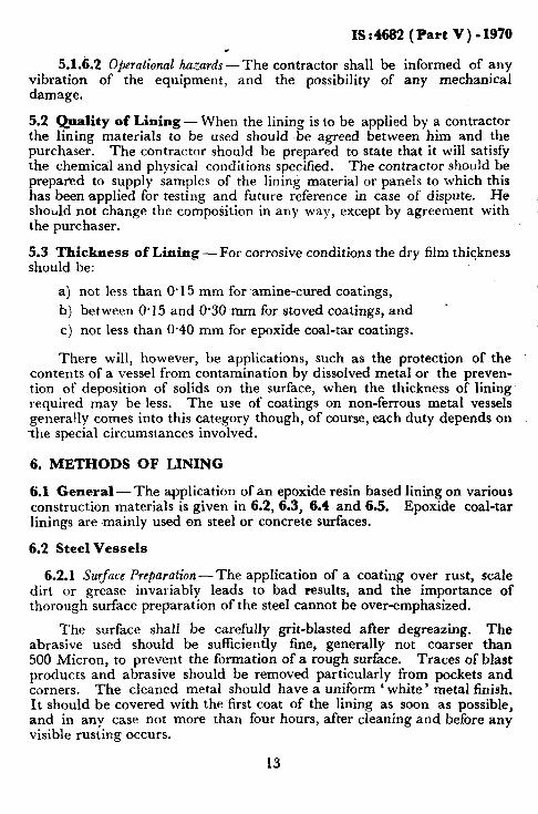
6.2.1 Surface Preparation-The application of a coating over rust, scale dirt or grease invariably leads to bad results, and the importance of thorough surface preparation of the steel cannot be over-emphasized.
The surface shall be carefully grit-blasted after degreazing. The abrasive used should be sufficiently fine, generally not coarser than 500 Micron, to prevent the formation of a rough surface. Traces of blast products and abrasive should be removed particularly from pockets and corners. The cleaned metal should have a uniform ‘ white’ metal finish. It should be covered with the first coat of the lining as soon as possible, and in any case not more than four hours, after cleaning and before any visible rusting occurs.
13
L

IS:4682 (Part V)-1970
To avoid condensation of moisture, the surface to which a lining is to,be applied should have a temperature at least 5°C above the dewpoint of the surrounding air before each coat is applied.
6.2.2 A@lication of Amine-Cured and Polyamide-Cured Lining-Amine- cured linings are supplied in two components, namely, the lining material and the curing agent. These two should be thoroughly mixed before use. When mixed, the lining should be applied within the time specified by the mafiufa,cturer ( usually 24 hours ).
6.2.2.1 It is recommended that the coats be applied by brush, especially the first, as brushing facilities bringing the lining material into close contact with the surface. To achieve satisfactory protection, at least four coats of a total dry thickness of at least 0.15 mm should be applied. Such applications consist usually of two primer coats and two finishing coats, although in‘some cases, three or more finishing coats may be desirable.
6.2.2.2 The recommendations of the manufacturer should be carefully observed as to the time interval between subsequent coats. These time intervals will depend on the composition of the coating system and the prevailing temperature. To ensure overall coverage, the primers as well as the finishing coats should be applied in different shades. Brush marks should be avoided particularly when applying the first coat.
6.2.2.3 At a temperature of 15°C to 2O”C, the lining will attain its full chemical resistance one week after application of the last coat. However, if the temperature falls below 15”C, after preliminary air drying, heat should be applied either by infra-red radiation or by hot air to each coat for one hour for curing. The surface temperature of the lining should n6t be raised above 60°C. When the last coat has been applied a curing time of three to six hours will generally be required at that temperature to ensure complete curing.
6.2.3 Application of Stoved Linings - Stoved linings should be sprayed on in a number of coats, each being allowed to air-dry. Five or more coats are recommended with intermediate stoving to assist the removal of sol- b.
vent. Intermediate stoving is done for a shorter time and at a tem- perature lower than the final stoving temperature, as otherwise the adhesion of the following coat would be insufficient. After applying the last coat, the equipment should be given the final stoving treatment in order to obtain a complete cure. The recommendation of the manufac- turer shall be carefully observed as to the time interval between subse- quent coats and the pot life.
6.2.4 Application of Epoxide-Coal-Tar Linings-Epoxide-coal-tar linings are supplied in two components which are to be mixed before use. They are applied by brushing or spraying at least two coats to a total dry thickness
14
IS t 4682 ( Part V ) - 1970
of not less than 0.40 mm. Some suppliers recommended the use of a pri- mer before application of these two coats. It is helpful to have shade differences bet%een alternate coats.
6.2.4.1 _4pplication techniques and curing are the same as for amine- cured linings, but the pot life is shorter.
6.3 Cast Iron Vessels -A clean surface of good qLlality cast iron may be lined with an amine-cured lining, but it is difficult to obtain the best results. The lining of large areas requires special care in order to ensure an even thickness and to avoid the formation of pin-holes or thin spots. As the surface is comparatively rough, the application of one or two coats more than on stx! surfaces under comparable conditions is recommended. Because of the natural porosity of cast iron, stoved linings should not be used unless special techniques are used, such as vacuum impregnation.
6.4 Other Metal Vessels -For stainless steel, copper, aluminium and their alloys the surface should be roughened by suitable means, such as blasting to improve adhesion of the lmmg.
6.42 Grit blasting should never be carried out with iron or steel contain- ing abrasives since this may result in staining or corrosion of the metal surface under the lining due to iron or steel particles becoming embedded in the non-ferrous metal surface. It is recommended that separate blasting grits be kept for different metals to prevent contamination.
6.5 Concrete Vessels -Because of their resistance to alkalis, amine- cured linings may be applied directly to concrete. Instead of a primer a cost of diluted finishing coat is first applied. The diluent to be used should be agreed to Letween the user and the supplier. The total lining generally consists of not less than four finishing coats of different shades to ensure overall coverage, these are applied by brush.
6.5.1 Epoxide-coal-tar-lining may be applied directly to concrete, no seal- ing coats being required. T\YO coats are generally applied by brush.
. .
7. ACCEPTANCE TESTS c
7.1 Completeness of Cure - The hardening of a stoved or amine-cured lining can be checked by determining the resistance of the film to methyl isobutyl ketone. When methyl isobutyl ketone is not available acetone may be used as a substitute.
7.1.1 This test may be carried out be laying a rag soaked in the solvent on the lining for three minutes, after which it should show no signs of softening. This may be checked by scratching with a finger nail. Any apparent softening indicates that the lining is not fully cured and further curing is required.
15

‘
IS:4682 (Part V)-1970
7.2 Tests for Continuitymof Lining
7.2.1 Visual Inspection -The inspection for visual defects should be carried out over the entire surface in a good light. The entire surface shall be free of cracks, traces of bubbles, lack of adhesion, hollow spaces, etc. Presence of hollow spaces may also be checked by tapping with a wooden mallet.
7.2.2 High-Frequency Spark Test - A high-voltage, high-frequency spark discharge should be directed at the 1inin.g. Where a defect occurs in the lining the discharge is earthed producmg a strong bluish-white conti- nuous spark. The surface of the lining should be clean and dry when the test is carried out. Excessive voltage or long residence time or both may puncture the lining, and care should, therefore, be taken to select the correct voltage and to ensure that the probe does not remain in one posi- tion for too long.
7.2.2.1 The voltage shall be 5 to 6 kV/mm thickness of the lining unless the lining contains considerable amount of carbon black filler in which case the voltage shall be l-5 kV/mm.
7.2.2.2 If it is necessary to carry out any machining of hard epoxide resin linings, machining or descaling or both of the vessel, the electric spark test should again be applied to the lining to ensure that it has not been damaged in any way.
7.3 Thickness of Lining-When called for by the user, the thickness of the covering should be checked in the areas specified. Where direct mea- surement is not possible, it should be carried out using a suitable thickness- meter.
7.4 Electrical Test
7.4.1 High-Voltage Test - The high-frequency spark tester, which is usually used for testing the thick linings dealt with in other parts of this code, should not be used for the thin linings dealt with in this part. The voltage required to produce a clearly visible spark is difficult to control and thin linings are likely to be punctured as a result of such testing.
L
7.4.1.1 A high-voltage direct current test should, therefore, be used. The probe is moved systematically over the surface to be tested, which should be clean and dry. Any pin-hole or crack will permit current to flow, and this is visible as an electric spark. There is no danger of pun- cturing the lining when the correct voltage required is adhered to, provid- ed the probe is not kept at the same place for a long time. The voltage required depends on the thickness of the lining to be tested and should be determined by trial on coated test plates.
16

IS : 4682 ( Part V ) - 1970
7.4.1.2 The lilting thickness on the test plate should be a minimum and the break-down voltage be determined on this plate. The voltage shou’ld then bp reduced to a valne of 75 percent of the break-down voltage. If at this conlparative low voltage the spark at a pin-hole is difficult to see, the instrument should be fitted with a neon indicator.
7.4.1.3 High-voltage test ~sets should have a high internal resistance or other means of limlttng the current to a safe value.
7.4.2 Resistance OY Cl’rt Tut-In this test one terminal of a 12-volt dc sl~pply is connected to the outer shell of the lined vessel and the other is joined. throllgh a milliamnleter, to a cotton-wool swab or sponge saturat- ed with a dilute (2 percent) aqueous solntion of ammonium hydroxide. The swab, is moved slowly over the whole surface of the lining so that any defect is indicatetl by a reading on the milliammeter.
7.4.2.1 Any vessel showing a large number of points of failure should be rejected. Where failure occurs over only a small area, local.patching may be allowed. In very slightly corrosive conditions, a few scattered imperfections may be tolerated, but for more stringent duties the electrical test should reveal no breakdown.
8. ROUTINE INSPECTION AND REPAIRS
8.1 Routine Inspection -To ensure the satisfactory operation of lined plant and equipment, it is necessary to carry out periodic inspections to make sure that the lining is sound. The frequency of these inspections will depend on the nature of the material being handled. During these inspections damage to the lining should be avoided by suitably covering footwear and ladders. Visual inspection, thickness tests and electrical tests should be carried out in accordance with 7.2.2 to 7.4 and 7.4.1.
8.2 Repairs - Damaged amine-cured epoxide resin or epoxide-coal-tar linings may he successfully repaired, but skilled labour’ is required in order to obtain good adhesion to the existing lining. To reline the da.maged areas they should be cleaned and roughened, preferably by blasting prior to lining.
8.2.1 Damaged stoved linings are usually repaired with amine-cured lining material in the same way, although this does not have the chemical resistance of stoved linings.
8.2.2 The lining applied may be dried by means of infra-red heaters.
17

IS : 4682 ( Part V ) - 1970
APPENDIX A ( Clauses 0.4 and 5.1 )
EXCHANGE OF INFORMATION
A-l. Early consultation and exchange of information should be arranged between all parties concerned with the design, use, manufacture and erection of vessels and equipment to be lined, land the lining contractor. Adequate and accurate scale drawings should be available to all parties concerned.
Consultations may be desirable on:
a)
b) Cl
d)
e> f 1
ET‘)
h)
3
k)
site conditions which may affect this particular work and the availability of services for site vulcanization;
safety measures to be taken during lining on site;
construction of equipment to be lined, location of welds joints and supports and the finish of the surface to be lined;
nature and concentration of media for which vessel or equipment is required;
operating temperatures land pressures;
other factors influencing material stress, for example, expansion, vibration or impact of contents on lining;
presence of abrasives in contents, and potential local erosion by fluids;
internal or external installation and means of access, lifting facilities, etc;
where necessary, the nature of the surface finish required of the lining;
service life; and
m) method of heating and cooling.
18
IS : 4682 ( Part V ) - 19?0
( Continued from page 2 )
Membus Rqhsen ting
SHRI R. S. Grtovrr,~ The Ralph M. Parsons Co of Asia, %mbay SHRI P.V. s. NAMBOOTRIRIPAD
( Alternate) SHIH H. H. JETHANANDANI The Fertilizer Corporation of India Ltd, New Delh? DB 0. P. KHARBANIJA Larsen c(r Toubro Ltd, Bombay SHRIJ. B. MALlK Burmah-Shell Refineries Ltd, Bombay
SHHI P. C. thLAICFlIA ( Alternate ) SHILI T. S. NAYAH Indian Institute of Petroleum ( CSIR ), Dehra Dun
SURI S. C. GUPTA ( Alkrnatc ) SHRI V. X4. RAO The K. C. P. Ltd, Madras
SHRI R. SATYANARAYANA (Alternate) DK D. S. VISWANATH Inc\iarl Institute of Science, Bangalore
19

BUREAU OF INDIAN STANDARDS
Headquarters :
~Manak Bhavan. 9 Bahadur Shah Zafar Marg. NEW DELHI 110002
Telephones : 331 01 31 Telegrams : Manaksanstha
331 13 75 (Common to all Offices) Regional Offices :
Central : Manak Bhavan, 9, Bahadur Shah Zafar Marg. NEW DELHI 110002
l Eastern : 1114 C.I.T. Scheme VII M, V.I.P. Road, Maniktola, CALCUTTA 700054
Northern : SC0 445-446, Sector 36-C, CHANDIGARH 160036 Southern
t Western : C.I.T. Campus, IV Cross Road, MADRAS 600113 : Manakalaya, E9 MIDC. Marol. Andheri (East),
BOMBAY 400093
Branch Offices :
‘Pushpak’, Nurmohamed Shaikh Marg, Khanpur, AHMADABAD 380001 r Peenya Industrial Area, 1st Stage. Bangalore-Tumkur Road,
BANGALORE 560058 Gangotri Complex, 5th Floor, Bhadbhada Road, T.T. Nagar,
BHOPAL 462003
Plot No. 82183, Lewis Road, BHUBANESHWAR -751002 Kalai Kathir Building, 6/48-A Avanasi Road, COIMBATORE 841037 Quality Marking Centre, N.H. IV, N,I.T., FARIDABAD 121001 Savitri Complex, 116 G. T. Road, GHAZIABAD 201001 5315 Ward No. 29, P.G. Barua Road, 5th By-lane.
GUWAHATI 781003 5-8-56C L. N. Gupta Marg. ( Nampally Station Road )
HYDERABAD 500001 RI4 Yudhister Marg, C Scheme, JAIPUR 302005
117/418 B Sarvodaya Nagar, KANPUR 208005
Plot No. A-9, House No. 561/63. Sindhu Nagar, Kanpur Roeo. LUCKNOW 226005
Patliputra Industrial Estate, PATNA 800013
Drstrict Industries Centre Complex. Bagh-e-Ali Maidan. SRINAGAFL 190011
T. C. No. 14/1421, University P. 0.. Palayam, THIRUVANANTHAPURAM 695034
/nspection Offices (With Sale Point) : Pushoaniali. First Floor, 205-A West Hiah Court Road.
Shank& Nagar Square, NAGPUR 4400’10 Institution of Engineers (India) Building, 1332 Shivaji Nagar.
PUNE 411005
‘Sales Offtce Calcutta is at 5 Chowringhee Approach. P. 0. Prmcep Street, CALCUTTA
t Sales Office is at Novelty Chambers, Giant Road, BOMBAY
_$ Sales Office is at Unity Building, Narasimharaja Square, BANGALORE
Telephone
! 331 01 31
333: tx
21843 41 2916
6329295
2 6348 3949 55
55 30 21
53627 267 05
- 8-71 19 96
331 77
231083
83471 21 6876
5 5507
62305 -
6 21 04
Il 52 51 71
52435
27 6800
89 65 28
223971
Reprography Unit, B-IS New Dej. i, India


![ras Oncogenes in Human Cancer: A Review1cancerres.aacrjournals.org/content/canres/49/17/4682.full.pdf · (CANCER RESEARCH 49. 4682-4689, September I. 1989] Review ras Oncogenes in](https://img.pdfslide.net/doc/110x75/5ade02567f8b9a213e8d8613/ras-oncogenes-in-human-cancer-a-cancer-research-49-4682-4689-september-i-1989.jpg)