Embed Size (px)
Citation preview

Disclosure to Promote the Right To Information
Whereas the Parliament of India has set out to provide a practical regime of right to information for citizens to secure access to information under the control of public authorities, in order to promote transparency and accountability in the working of every public authority, and whereas the attached publication of the Bureau of Indian Standards is of particular interest to the public, particularly disadvantaged communities and those engaged in the pursuit of education and knowledge, the attached public safety standard is made available to promote the timely dissemination of this information in an accurate manner to the public.
इंटरनेट मानक
“!ान $ एक न' भारत का +नम-ण”Satyanarayan Gangaram Pitroda
“Invent a New India Using Knowledge”
“प0रा1 को छोड न' 5 तरफ”Jawaharlal Nehru
“Step Out From the Old to the New”
“जान1 का अ+धकार, जी1 का अ+धकार”Mazdoor Kisan Shakti Sangathan
“The Right to Information, The Right to Live”
“!ान एक ऐसा खजाना > जो कभी च0राया नहB जा सकता है”Bhartṛhari—Nītiśatakam
“Knowledge is such a treasure which cannot be stolen”
“Invent a New India Using Knowledge”
है”ह”ह
IS 534 (2007): Benzene [PCD 3: Petroleum, Lubricants andtheir Related Products]


IS 534:2007
Indian Standard
BENZENE — SPECIFICATION
(Fourth Revision )
ICS 71.080.15
0 BIS 2007
BUREAU OF INDIAN STANDARDSMANAK BHAVAN, 9 BAHADUR SHAH ZAFAR MARG
NEW DELHI 110002
November 2007 Price Group 11
Petroleum, Lubricants and Their Related Products Sectional Committee, PCD 3
FOREWORD
This Indian Standard (Fourth Revision) was adopted by the Bureau of Indian Standards, after the draft finalizedby the Petroleum, Lubricants and Their Related Products Sectional Committee had been approved by the Petroleum,Coal and Related Products Division Council.
Benzene is derived by suitable fractionation and refining by washing with acid or hydrorefining of crude benzolerecovered from the gas produced during carbonization of coal in coke ovens and retorts or recovered as by-product in petroleum refining or petrochemical operations.
Earlier benzene was essentially a coal base product being made available as by-product from coke ovens of steelplants. The requirements and methods of test were also stipulated on the basis of the publications by NationalBenzole and Allied Products Association (NBA) and the Standardization of Tar Products Test Committee (STPTC),UK in order to suit the prevailing quality of the product. However, cognizance was taken of the fact that consequentupon exploration of oil fields in the recent past specially the Bombay High, substantial quantities of indigenouscrude was being made available, which has completely changed the scenario. On a quantum basis there is adistinct shift in production of various aromatic hydrocarbons from coal base to petroleum base as a result ofwhich benzene is currently being made available in abundance. The Committee, therefore, decided to update the
standard in accordance with the latest developments in the field, both in production and usage and in the light ofthe experience gained in the past.
This standard was first published in 1955. In view of the growing demand for benzene for organic synthesis itwas considered necessary to include the material for this end use also. It was also felt that pure and ordinary
grades of the material should be brought under a composite standard on the subject. The standard was, therefore,revised in 1965 amalgamating with IS 535: 1955 ‘Specification for benzene, pure, nitration grade’. In the secondrevision, the method of test for total sulphur was replaced by Raney nickel method, as the latter was found moreconvenient and reliable. Various changes covered under Amendment No. 1 issued in March 1973 were alsoincorporttted in the third revision.
In the third revision in 1992, keeping in view various end uses and the source of crude base, benzene was
classified into three types. In view of stringent quality of benzene required for the manufacture of caprolactam,it was decided to incorporate additional requirement of aliphatic and aromatic impurities and bromine index.
In the present revision, Type C has been deleted in order to align with the International practices. Additionalrequirements like purity of benzene by GC method including percent of toluene, non-aromatic hydrocarbons 1,4
dioxane, carbon disulphide, N-formylmorphine as nitrogen, residue on evaporation and n-heptane have beenincluded, in addition to making the requirements of other characteristics more stringent. Requirements like coppercorrosion and neutrality have been deleted.
‘IS 1840:1961 Benzene, reagent grade’ has been withdrawn, as it was observed by the technical committee, that
this standard would cover the requirements of reagent grade benzene.
In the formulation of this standard, considerable assistance has been drawn from the following standards publishedby International Organization for Standardization (1S0) and American Society for Testing and Materials, USA:
ASTM D 835:1995 Standard specification for refined benzene — 485 (withdrawn)
ASTM D 848:1997 Standard test method for acid wash color of industrial aromatic hydrocarbonsASTM D 850:1999 Standard test method for distillation of industrial aromatic hydrocarbons and related
materialsASTM D 852:1997 Standard test method for solidification point of benzeneASTM D 853:1997 Standard test method for hydrogen sulfide and sulfur dioxide content (qualitative)
of industrial aromatic hydrocarbons
(Continued on third cover)
IS 534:2007
Indian Standard
BENZENE — SPECIFICATION
(Fourth
1 SCOPE
This standard prescribes the requirements and themethods of sampling and tests for benzene.
2 REFERENCES
The following standards contain provisions which,
through reference in the text, constitute provisions ofthis standard. At the time of publication, the editionsindicated were valid. All standards are subject to revision,and parties to agreements based on this standard areencouraged to investigate the possibility of applying themost recent editions of the standards indicated below:
IS No.
82:1973
1070:19921260 (Part 1):
1973
1446:2002
4644:1968
4905:1968
5165:1969
Title
Method of sampling and test forthinners and solvents for paints @-strevision)
Reagent grade water (third revision)Pictorial marking for handling andlabelling of goods: Part 1 Dangerous
goods (ftrst revision)Classification of dangerous goods
(secortd revision)Code of safety for benzene, tolueneand xyleneMethods for random samplingInterchangeable conical ground-
glass joints
3 TERMINOLOGY
For the purpose of this standard, the definitions givenin IS 82 and the following shall apply.
3.1 Bromine Index — The number of milligrams of
bromine consumed by 100 g of sample under givenconditions.
3.2 Solidification Point — An empirical constantdefined as the temperature at which the liquid phaseof a substance is in approximate equilibrium with arelatively small portion of the solid phase.
4 TYPES
There shall be two types of material, namely:
a) Type A —
b) Type B —
Suitable for manufacture ofcaprolactam; and
Suitable for manufacture ofother products
Revision )
5 REQUIREMENTS
5.1 Description
The material shall be a clear liquid, free of sediments
and haze when observed at 18° to 26”C.
5.2 The material shall comply with the requirementsas given in Table 1.
6 PACKING, MARKING AND STORAGE
6.1 Packing and Storage
6.1.1 The material shall be packed as agreed to betweenthe purchaser and the supplier.
6.1.2 All the containers in which the material is packedshall be dry, clean, and free from substances solublein benzene and leak proof.
6.1.3 The containers shall be securely closed, protectedfrom light, and shall be stored in a cool place.
6.1.4 The containers for storage and transport of thematerial, since classified as flammable and dangerousgoods, shall, in addition comply with the requirements
of the latest issue of Red Tariff and the requirementsas laid down from time to time by the Chief Controllerof Explosives, Government of India, for packing,storage and transit of flammable liquids and the Boardof Trade Regulations as applicable thereon for transportby steamers.
6.1.5 Necessary safeguards against the risk arising fromthe storage and handling of large volumes of flammableliquids (see IS 1446) shall be provided and all dueprecautions shall be taken [see IS 1260 (Part 1)] at alltimes to prevent accidents by fire or explosion.
6.1.6 Except when they are opened for the purpose ofcleaning and rendering them free from benzene vapour,all empty tanks or other containers shall be keptsecurely closed unless they have been thoroughlycleaned and freed from benzene vapour.
6.2 Marking
6.2.1 Each container shall be securely closed andmarked legibly and indelibly with the followinginformation:
a) Name and type of the material,
b) Indication of the source of manufacture,
c) Net mass of the material in the container,
1
IS 534:2007
d) Batch number or code number, and
e) Date of manufacture.
6.2.2 Each container shall have the caution label‘FLAMMABLE’ together with the correspondingsymbol for labelling of dangerous goods as given inIS 1260 (Part 1).
6.2.3 BIS Certification Marking
The containers may also be marked with the BISCertification Mark.
6.2.3.1 The use of the Standard Mark is governed bythe provisions of Bureau of Indian Standards Act, 1986and the Rules and Regulations made thereunder. Thedetails of conditions under which the licence for theuse of the Standard Mark may be granted tomanufacturers or producers may be obtained from theBureau of Indian Standards.
7 HANDLING
Benzene is highly toxic and therefore it shall be handled
carefully (see IS 4644). Exposure of benzene inatmosphere should be monitored regularly. Personsexposed to benzene shall be periodically checkedaccording to State Factory Rules and Local StateRegulations.
8 SAMPLING
Representative samples of the material shall beprepared as prescribed in Annex M.
9 TEST METHODS
9.1 Tests shall be conducted according to the methodsreferred to in CO15 of Table 1.
9.2 Quality of Reagents
Unless otherwise specified, pure chemicals anddistilled water (see IS 1070) shall be employed in
tests.
NOTE — ‘Pure chemicals’ shall mean chemicals that do notcontain impurities,which affect the results of analysis.
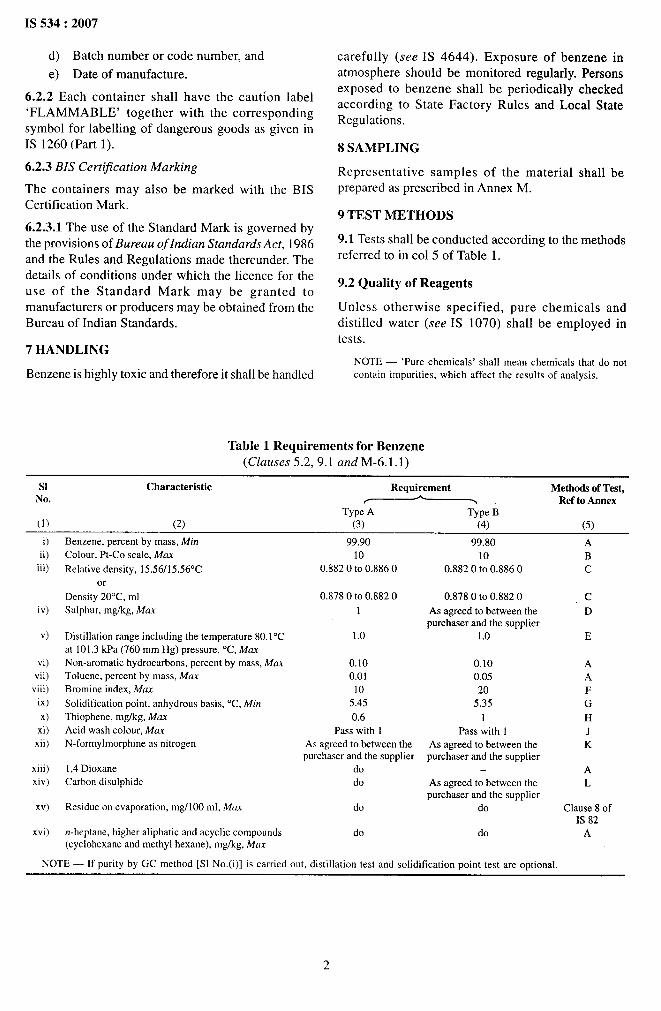
Table 1 Requirements for Benzene(Clauses 5.2,9.1 and M-6.1. 1)
S1 Characteristic Requirement Methods of Test,No. A< -1 Ref to Annex
TypeA TypeB(1) (2) (3) (4) (5)
Oii)
iii)
iv)
v)
vi)vii)
viii)ix)x)
xi)xii)
xiii)xiv)
xv)
xvi)
Benzene,percentby mass,Min
Colour,Pt-Coscale,Max
Relativedensity, 15.56/15.56°Cor
Density20”C,mlSulphur,mg/kg,Ma
Distillationrangeincludingthe temperature80.1‘Cat 101.3kPa (760mm Hg)pressure,“C,MaxNon-aromatichydrocarbons,percentby mass,Mux
Toluene,percentby mass,MaxBromineindex,Max
Solidificationpoint,anhydrousbasis,“C,MinThiophene,mgikg,MaxAcidwashcolour,MaxN-formylmorphineas nitrogen
1,4DioxaneCarbondisulphide
Residueon evaporation,mg/100ml,Max
n-heutane,higheraliphaticandacycliccom~ounds(cycjohexane-andm&hylhexane):mgikg,~az
99.9010
0.8820 to 0.8860
0.8780 to 0.88201
1.0
0.100.0110
5.450.6
Passwith 1As agreedto betweenthepurchaserandthe supplier
dodo
do
do
99.8010
0.8820 to 0.8860
0.8780 to 0.8820As agreedto betweenthepurchaserand the supplier
1.0
0.100.05
205.35
1Pass with 1
As agreedto betweenthepurchaserandthe supplier
—As agreedto betweenthepurchaserand the supplier
do
do
ABc
c
D
E
AAFGHJK
AL
Clause8 ofIS 82
A
NOTE— If purity by GC method [S1No.(i)] is carried out, distillationtest and solidificationpoint test are optional.
IS 534:2007
ANNEX A
[Table 1, S1 No. (i), (vi), (vii), (xiii) and (xvi)]
DETERMINATION OF PURITY OF BENZENE BY GC
A-1 OUTLINE OF THE METHOD
A-1.l A known amount of an internal standard isadded to the specimen. A small volume of this mixtureis injected into a gas chromatography equipped with aflame ionization detector (FID) and a capillarycolumn.
A-1.2 The peak area of each impurity and the internalstandard is measured by an electronic integrator. Theconcentration of each impurity is calculated from theratio of the peak area of the internal standard versusthe peak area of the impurity. Purity is calculated bysubtracting the sum of the impurities found from100,00 mass, percent. Results are reported in mass,
percent.
A-2 INTERFERENCES
A-2.1 Benzene is typically resolved from naturallyoccurring components with boiling points less than138”C. Naturally occurring components include non-
aromatic hydrocarbons, toluene, C8 aromatics and 1,4-dioxane. An adequate separation of known impuritiesfrom benzene should be evaluated for the column
selected.
A-2.2 The internal standard chosen shall be sufficientlyresolved from any impurity and the benzene peak.
A-3 APPARATUS
A-3.1 Gas Chromatograph — Any chromatographyhaving a flame ionization detector that can be operatedat the conditions given in Table 2 may be used. Thesystem should have sufficient sensitivity to obtain aminimum peak height response for a 0.000 5 mass,
percent impurity twice the height of the signalbackground noise.
A-3.2 Electronic Integrator — Computer based
capable of handling internal standard calculations andpeak grouping is recommended.
A-3.3 Column — Fused silica capillary column with
crosslinked polyethylene glycol stationary phase isrecommended. Alternate stationary phases may be usedif they produce at least the same aromatic separation
and elute Cg non-aromatic impurities before benzene.
A-3.4 Microsyringes, 10 and 100 !-d capacity.
A-4 REAGENTS AND MATERIALS
A-4.1 Carrier Gas, chromatographic grade helium isrecommended.
3
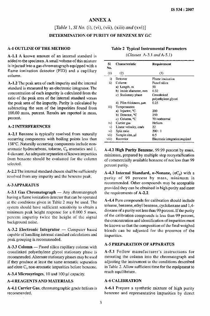
Table 2 fipical Instrumental Parameters
(Clauses A-3. 1 andA-5. 1)
S1 Characteristic RequirementNo.
(1) (2) (3)
Oii)
iii)
iv)v)
vi)vii)
viii)
DetectorColumn:a) Length,mb) Insidediameter,mmc) Stationaryphase
d) Filmthickness,~mTemperatures:a) Injector,“Cb) Detector,“Cc) Column,“CCarriergasLinearvelocity,crdsSplitratioSamplesize,@Recorder
FlameionizationFusedsilica500.32Crosslinkedpolyethyleneglycol0.25
20025070 isothermalHelium22200:10.5Electronicintegrationrequired
A-4.2 High Purity Benzene, 99.99 percent by mass,
minimum, prepared by multiple step recrystallization
of commercially available benzene of not less than 99
percent purity.
A-4.3 Internal Standard, rz-Nonane, (nC,J with apurity of 99 percent by mass, minimum isrecommended. Other compounds may be acceptableprovided they can be obtained in high purity and meet
the requirements of A-2.2.
A-4.4 Pure compounds for calibration should include
toluene, benzene, ethyl benzene, cyclohexane and 1,4-dioxane of a purity not less than 99 percent. If the purity
of the calibration compounds is less than 99 percent,the concentration and identification of impurities mustbe known so that the composition of the final weighed
blends can be adjusted for the presence of theimpurities.
A-5 PREPARATION OF APPARATUS
A-5.1 Follow manufacturer’s instructions formounting the column into the chromatography and
adjusting the instrument to the conditions described
in Table 2. Allow sufficient time for the equipment toreach equilibrium.
A-6 CALIBRATION
A-6.1 Prepare a synthetic mixture of high puritybenzene and representative impurities by direct
IS 534:2007
weighing. Weigh each impurity tothenearest O.l mg.Table 3 contains a typical calibration blend.Cyclohexane is used for the non-aromatic portion andethyl benzene for the C8 aromatic portion.
Table 3 ‘&pical Calibration Blend, G
S1No. Compound Weight, Percent
(1) (2) (3)
i) Benzaie 99.0000ii) Toluene 0.0500iii) Cyclohexane 0,0500iv) Elhylbenzene 0.0500\) 1,4Dioxane 0.0200
A-6.2 Using the exact mass for each impurity, calculate
the percent by mass, concentration of the calibrationblend.
A-6.3 Into a 50-ml volumetric flask, add 50 ml of nCg
to 49.95 ml of the calibration blend and mix well. Usinga density of 0.874 g/ml for the calibration blend and adensity of 0.718 g/ml for the nCg, the resulting nCgconcentration will be 0.0825 percent by mass.
A-6.4 Inject 0.5 L1 of the blend with internal standardinto the chromatography and integrate the area under
each peak, excluding benzene.
A-6.5 Calculate the relative response factors (RRF) asfollows:
RRFi = (A,)(Ci)/(CJ(Ai)
RIa)
zI a)N cc $c% L’
where
RRFi = impurity, i;
A, = peak area of internal standard;
Ai = peak area of impurity, i;
Ci = percent by mass, impurity, i, from A-6.2;and
c,, = concentration of internal standard, percentby mass from A-6.3.
A-7 PROCEDURE
A-7.1 Into a 50-ml volumetric flask, add 50 U1of nCginternal standard and dilute to the mark with specimen.Mix well.
A-7.2 Inject 0.5 IN of mixture into the chromatography.
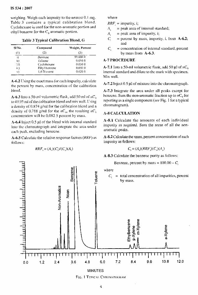
A-7.3 Integrate the area under all peaks except forbenzene. Sum the non-aromatic fraction up to nCg forreporting as a single component (see Fig. 1 for a typical
chromatogram).
A-8 CALCULATION
A-8.1 Calculate the amounts of each individualimpurity as required. Sum the areas of all the non-aromatic peaks.
A-8.2 Calculate the mass, percent concentration of each
impurity as follows:
Ci = (Ai)(RRFi)(CJ(AJ
A-8.3 Calculate the benzene purity as follows:
Benzene, percent by mass= 100.00- Ci
where
Ci = total concentration of all impurities, percentby mass.
-1I I I l“’’I’’’’ 1’’’’ 1’’’’ 1’’’’ 1’’’’ 1’’’’ 1’’’’ 1’’”1
0.0 1.2 2.4 3.6 4.8 6.0 7.2 8.4 9.6 10.8 12.0
MINUTES
FIG. 1 TYPICALCIIROMATOGRAM
4
IS 534:2007
ANNEX B
[Table 1, S1 No. (ii)]
DETERMINATION OF COLOUR (PLATINUM-COBALT SCALE)
B-1 OUTLINE OF THE METHOD
Vkual comparison of the colour of a sample with that ofcolour standard, and expression of the result in terms ofHazen (platinum-cobalt) colour units. For routine control
purposes an instrument such as a comparator, calorimeteror spectrophotometer may be used, provided that it hasfirst been established that the results so obtained areidentical with those obtained by visual comparison.
B-2 DEFINITION
B-2.1 Hazen Colour Unit — The colour of a solution
containing 1 mg of platinum per litre in the form ofchloroplatinic acid, in the presence of 2 mg of cobalt(II) chloride hexahydrate per litre.
B-3 CHEMICALS
B-3.1 Cobalt (II) Chloride Hexahydrate
(COC12.6H20)
B-3.2 Hydrochloric Acid — approximately 1.19 g/ml. About 38 percent (mlnz) solution, or approximately12 N solution.
B-3.3 ChloroplatinicAcid — Dissolve 1.00 g platinumin a sufficient quantity of aqua regia in a glass or
porcelain dish by heating on a boiling water bath. Whenthe metal has dissolved, evaporate the solution todryness. Add 4 ml of the hydrochloric acid solution(B-3.2) and again evaporate to dryness. Repeat thisoperation twice more. In this way 2.10 g ofchloroplatinic acid (HqPtCIJ are obtained.
or
B-3.4 Potassium Chloroplatinate (KzPtCIJ
B-4 APPARATUS
B-4.1 Two Calorimetric ‘Ihbes, flat based if possible,with a graduation mark at least 100 mm above the baseand matched especially with respect to colour of glassand height of graduation mark above the base. Suitable
tubes are available commercially as 50 id or 100 mlNessler cylinders.
For the measurement of low colorations (less than 50Hazen units), the height of the graduation mark above
the base must be greater than for the measurement ofdeeper colours and must be sufficient that, on lookingthrough this greater depth of liquid, a clear distinction
between the standard Hazen matching solution can beobserved.
B-5 PREPARATION OF STANDARDCALORIMETRIC SOLUTIONS
B-5.1 Standard Calorimetric Solution, 500 HazenUnits — Dissolve 2.00 g of the cobalt chloride(see B-3.1), and the equivalent of 1.00 g of platinum,that is either 2.10 g of the chloroplatinic acid (see B-3.3),or 2.49 g of the potassium chloroplatinate (see B-3.4),in water in a 2 000-ml one-mark volumetric flask, add200 ml of the hydrochloric acid solution (see B-3.2),dilute to the mark and mix. This solution has a colour of500 Hazen colour units.
B-5.2 Standard Hazen Matching Solution (Diluted
Solution) — Into two series of ten 500-ml and fourteen250-ml one-mark volumetric flasks, place the volumesof standard calorimetric solution (see B-5.1) shown inTable 4, dilute to the mark and mix.
B-5.3 Storage
Store these solutions (see B-5.1 and B-5.2) in the darkin stoppered glass bottles. Under these conditions thecolour standard solution (see B-5.1) is stable for at least
one year. The standard Hazen matching solution(see B-5.2), although stable for at least one month shallpreferably be prepared fresh.
B-6 PROCEDURE
B-6.1 First check visually that the sample has colourcharacteristics close to those of the standard Hazenmatching solution (see B-5.2). If not, follow theinstructions given in B-7.2.
B-6.2 Pour into one of the calorimetric tubes
(see B-4.1) a quantity of the sample sufficient to fill itto the graduation mark. Similarly pour the standardHazen matching solution (see B-5.2) which appears
to have a similar colour into the other tube to the mark.
B-6.3 Compare the colour of the sample with that of
the standard, by looking down the tubes from top tobottom against a white background stronglyilluminated by daylight or by an electric ‘daylight’lamp, taking care to avoid any side illumination.
B-6.4 Repeat, if necessary, with other standard Hazenmatching solutions until the closest match is obtained.
NOTES1 Instrumentsare availablewhichpermitvisualcomparisonofa liquid of a given depth, with a moving tinted glass disccorresponding to the different standard Hazen matchingsolutions. The use of such instruments, whose standards are
5
IS 534:2007
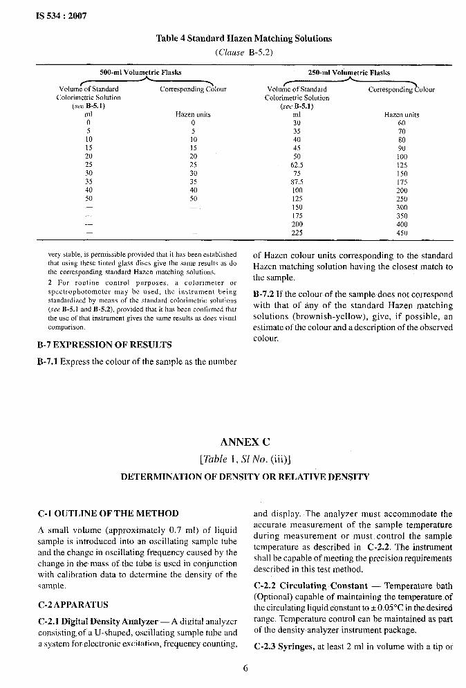
Table 4 Standard Hazen Matching Solutions
(Clause B-5.2)
500-ml Volumetric Flasks 250-ml Volumetric Flasks
FVolume of Standard
7Corresponding Co[our Volume of Standard
Calorimetric Solution Calorimetric Solution(see B-5.1) (see B-5.1)
ml Hazen units ml Hazen unitso 0 30 605 5 35 7010 10 40 8015 15 45 9020 20 50 10025 25 62.5 12530 30 75 15035 35 87.5 17540 40 I 00 20050 50 125 250— 150 300— 175 350— 200 400— 225 450
very sr~ble, is permissible provided that it has been established of Hazen colour units corresponding to the standardthat using these tinted glass discs give the same results as do Hazen matching solution having the closest match tothe corresponding standard Hazen matching solutions.
2 For routine control purposes, a calorimeter orthe sample.
spectrophotometer may be used, the instrument being B-7.2 If the colour of the sample does not correspondstandardized by means of the standard calorimetric solutions(see B-5.1 and B-5.2), provided that it has been corrlirmed that
with that of @y of the standard Hazen matching
the use of that instrument gives the same results as does visual solutions (brownish-yellow), give, if possible, ancomparison, estimate of the colour and a description of the observed
B-7 EXPRESSION OF RESULTScolour.
B-7.1 Express the colour of the sample as the number
ANNEX C
[Table 1, S1No. (iii)]
DETERMINATION OF DENSITY OR RELATIVE DENSITY
C-1 OUTLINE OF THE METHOD
A small volume (approxknately 0.7 ml) of liquid
sample is introduced into an oscillating sample tubeand the change in oscillating ffequeney caused by thechange in the mass of the tube is used in conjunctionwith calibration data to determine the density of the
sample.
C-2 APPARATUS
C-2.1 Digital Density Anal@er — A cli~ital analyzerconsisting of a U-shaped, oscillating sample tube anda system forelectronic excitation, frequency counting,
and display. The analyzer must accommodate theaccurate measurement of the sample temperature
during measurement or must control the sampletemperature as described in C-2.2. The instrumentshall be capable of meeting the precision requirementsdescribed in this test method.
C-2.2 Circulating Constant — Temperature bath(Optional) capable of maintaining the temperature ofthe circulating liquid constant tot 0.05°C in the desired
range. Temperature control can be maintained as partof the density analyzer instrument package.
C-2.3 Syringes, at least 2 ml in volume with a tip or
6
IS 534:2007
an adapter tip that will fit the opening of the oscillatingtube.
C-2.4 Flow-Through or Pressure Adapter, for useas an alternative means of introducing the sample intothe density analyzer either by a pump or by vacuum.
C-2.5 Thermometer, calibrated and graduated to0.1 ‘C, and a thermometer holder that can be attachedto the instrument for setting and observing the testtemperature. In calibrating the thermometer, the ice
point and bore connections should be estimated to thenearest 0.05°C.
C-3 REAGENTS AND MATERIALS
C-3.1 Water, redistilled, freshly boiled and cooledreagent water (see IS 1070) for use as a primarycalibration standard.
C-3.2 Petroleum Naphtha, for flushing viscouspetroleum samples from the sample tube.
Warning — EXTREMELYFLAMMABLE.
C-3.3 Acetone, for flushing and drying the sampletube.
Warning — EXTREMELYFLAMMABLE.
C-3.4 Dry Air, for blowing the oscillator tube.
C-4 PREPARATION OF APPARATUS
Set up the density analyzer and constant temperaturebath following the manufacturer’s instructions. Adjustthe bath or internal temperature control so that the
desired test temperature is established and maintainedin the sample compartment of the analyzer. Calibrate
the instrument at the same temperature at which thedensity of the sample is to be measured.
Caution — Precise setting and control of the testtemperature in the sample tube is extremely important. Anerror of 0. I “C can result in a change in density of one in thefourth decimal,
C-5 CALIBRATION OF APPARATUS
C-5.1 Calibrate the instrument when first set up andwhenever the test temperature is changed. Thereafter,conduct calibration checks at weekly intervals duringroutine operation.
C-5.2 Initial calibration, or calibration after a change intest temperature, necessitates calculation of the valuesof the constants A and B from the periods of oscillation
(T) observed when the sample cell contains air andredistilled, freshly boiled and cooled reagent water. Other
calibrating materials such as n-nonane, n-tridecane,cyclohexane, and n-hexadecane (for high temperatureapplications) can also be used as appropriate.
C-5.2.1 While monitoring the oscillator period, T, flushthe sample tube with petroleum naphtha, followed with
an acetone flush and dry with dry air. Contaminated orhumid air can affect the calibration. When theseconditions exist in the laboratory, pass the air used forcalibration through a suitable purification and dryingtrain. In addition, the inlet and outlet ports for theU-tube must be plugged during measurement of thecalibration air to prevent ingress of moist air.
C-5.2.2 Allow the dry air in the U-tube to come tothermal equilibrium with the test temperature andrecord the T-value for air.
C-5.2.3 Introduce a small volume (about 0.7 ml) ofredistilled, freshly boiled and cooled reagent water intothe sample tube from the bottom opening using asuitable syringe. The test portion must be homogeneousand free of even the smallest air or gas bubbles. Thesample tube does not have to be completely full as longas the liquid meniscus is beyond the suspension point.Allow the display to reach a steady reading and recordthe T-value for water.
C-5.2.4 Calculate the density of air at the temperatureof test using the following equation:
d,,, g/ml = 0.001293 [273.15/T][ P/760] ............ (1)
where
T = temperature, K and
P = barometric pressure, torr.
C-5.2.5 Determine the density of water at thetemperature of test by reference to Table 5.
C-5.2.6 Using the observed T-values and the referencevalues for water and air, calculate the values of theconstants A and B using the following equations:
A = [TW2- T: ] / [ dW-dJ ......................... (2)
B= Ta2–(AXdJ ........................................ (3)
where
TW = observed period of oscillation for cell
containing water,
T,, = observed period of oscillation for cell
containing air,
dW = density of water at test temperature, and
d. = density of air at test temperature.
Alternatively, use the T and d values for the otherreference liquid, if one is used.
C-5,2.7 If the instrument is equipped to calculatedensity from the constants A and B and the observedT-value from the sample, then enter the constants inthe instrument memory in accordance with themanufacturer’s instructions.
C-5.2.8 Check the calibration and adjust, if needed by
performing the routine calibration check describedin C-5.3.
7
IS 534:2007
C-5.2.9 To calibrate the instrument to display relativedensity, that is, the density of the sample at a giventemperature referred to the density of water at the sametemperature, follow sections C-5.2.1 through C-5.2.7.Substitute 1.000 for dWin performing the calculationsdescribedin C-5.2.6.
C-5.3 Weekly calibration adjustments to constants Aand B can be made if required, without repeating thecalculation procedure.
NOTE — The need for a change in calibration is generallyattributableto depositsin the sampletube that are not removedby the routineflushingprocedure.Althoughthis conditioncanbe compensatedfor by adjustingA and B, it is good practicetoclean the tube with warm chromic acid solution (Warning —Causes severe burns). A recognized carcinogen), wheneveramajoradjustmentis required.Chromicacid solutionis themosteffectivecleaning agent; however, surfactant cleaning fluidshave also been used successfully.
C-5.3.1 Flush and dry the sample tube as describedin C-5.2.1 and allow the display to reach a steadyreading. If the display does not exhibit the correct
density for air at the temperature of test, repeat thecleaning procedure or adjust the value of constant Bcommencing with the last decimal place until thecorrect density is displayed.
C-5.3.2 If adjustment to constant B was necessaryin C-5.3.1 then continue the recalibration by introducingredistilled, freshly boiled and cooled reagent water into
the sample tube as described in C-5.2.3 and allow thedisplay to reach a steady reading. If the instrument hasbeen calibrated to display the density, adjust the readingto the correct value for water at the test temperature(see Table 5) by changing the value of constant A,commencing with the last decimal place. If theinstrument has been calibrated to display the relativedensity, adjust the reading to the value 1.0000.
NOTE— In applying this weekly calibration procedure, it can
be found that more than one value each for A and B, differingin the fourth decimal place, will yield the correct densityreading for the density of air and water. The setting chusenwould then be dependent upon whether it was appruachcd from
Temperature Density
‘c glml
0.0 0.9998403.0 0.9999644,0 0.9999725.0 0.999964
10.0 0.99969915.0 0,99909915.56 0.99901216.0 0.99894317.0 0.99877418.0 0.99859519.0 0.99840420.0 0.998203
a higher or lower vahse. The setting selected by this methodcould have the effect of altering the fourth place of the readingobtained for a sample.
C-5.4 Some analyzer models are designed to displaythe measured period of oscillation only (T-values) andtheir calibration requires the determination of aninstrument constant K, which must be used to calculatethe density or relative density from the observed data.
C-5.4.1 Flush and dry the sample tube as describedin C-5.2.1 and allow the display to reach a steadyreading. Record the T-value for air.
C-5.4.2 Introduce redistilled, freshly boiled and cooledreagent water into the sample tube as describedin C-5.2.3. allow the display to reach a steady readingand record the T-value for water.
C-5.4.3 Using the observed T-values and the referencevalues for water and air (see C-5.2.4 and C-5.2.5),calculate the instrument constant K using the followingequations:
For density:
K1=[dW–d, ]/[ TW2– Ta2] ........................ (4)
For relative density:
K2 = [ 1.000 O–da] / [ TW2– T,*] ............... (5)
where
TW =
T7 =
dW =
d,, =
observed period of oscillation for cellcontaining water,
observed period of oscillation for cellcontaining air,
density of water at test temperature, and
density of air at test temperature.
C-6 PROCEDURE
C-6.1 Introduce a small amount (about 0.7 ml) ofsample into the clean, dry sample tube of the instrumentusing a suitable syringe.
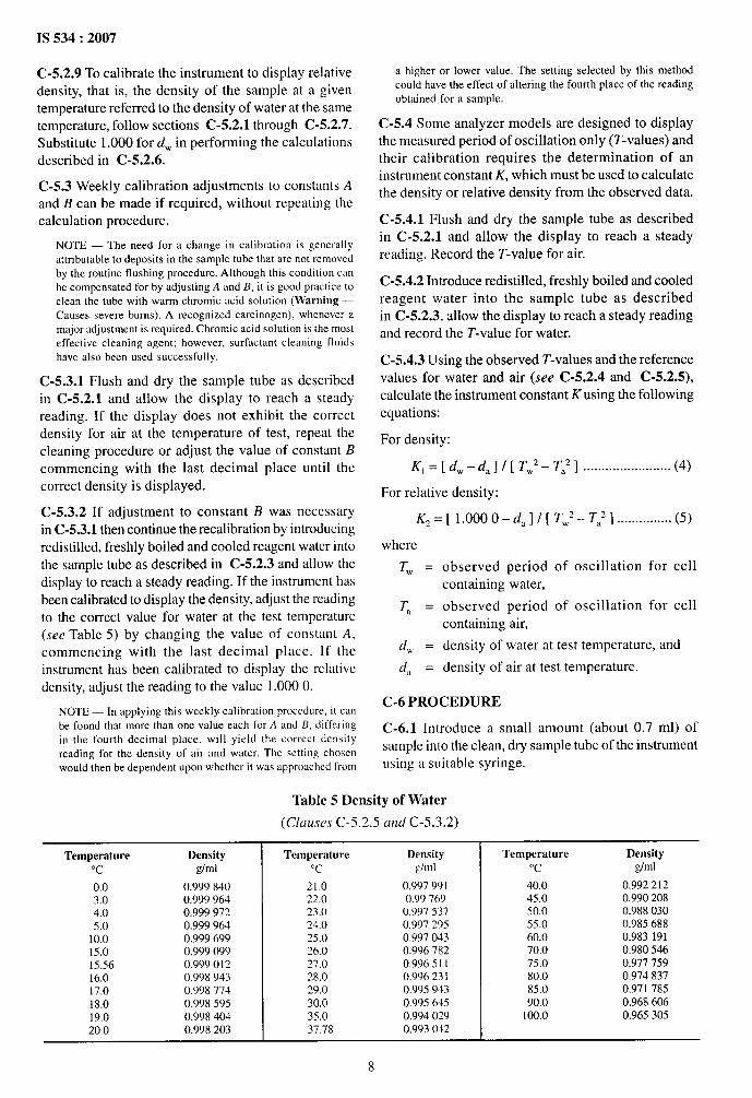
Table 5 Density of Water
(Ckuses C-5.2.5 and C-5.3.2)
Temperature Density
“c glml
21.0 0.99799122.0 0,9976923,0 0.99753724.0 0.99729525.0 0.99704326.0 0.99678227.0 0.99651128.0 0.99623129.0 0.99594330.0 0.99564535,0 0.99402937.78 0.993042
Temperature Density“c glml
40.0 0.99221245,0 0.99020850.0 0.98803055.0 0.98568860.0 0.98319170.0 0.98054675,0 0.97775980.0 0.97483785.0 0.97178590.0 0.968606
100.0 0.965305
8
C-6.2 The sample can also be introduced by siphoning.Plug the external TFE-fluorocarbon capillary tube intothe lower entry port of the sample tube. Immerse theother end of the capillary in the sample and applysuction to the upper entry port using a syringe orvacuum line until the sample tube is properly filled.
C-6.3 Turn on the illumination light and examine thesample tube carefully. Make sure that no bubbles aretrapped in the tube, and that it is filled to just beyondthe suspension point on the right hand side. The samplemust be homogeneous and free of even the smallestbubbles.
NOTE— If the sample is too dark in color to determinetheabsence of bubbles with certainty, the density cannot bemeasuredwithin the stated precision limits.
C-6.4 Turn the illumination light off immediately aftersample introduction, because the heat generated canaffect the measurement temperature.
C-6.5 After the instrument displays a steady readingto four significant figures for density and five for T-values, indicating that temperature equilibrium has
been reached, record the density or T-value.
C-7 CALCULATION
C-7.1 Calculating Density Analyzers
The recorded value is the final result, expressed either
IS 534:2007
as density, in g/ml or g/m3, or as relative density.
NOTE— kg/m’= 1000 x g/ml.
C-7.2 Non-calculating Density Analyzers
Using the observed T-value for the sample and theT-value for water and appropriate instrument constants
determined as in C-5.4.3, calculate the density orrelative density using Equations 6 and 7. Carry out all
calculations to six significant figures and round thefinal results to four.
For density:
density, g/ml (kg/dm3) at t= dw + K, (T$ - TW2)... (6)
For relative density:
relative density, t/t= 1 +
where
TW =
T, =
dW =
K1 =
Kz =
t =
observed periodcontaining water;
observed period
Kz (TS2- TW2).......... (7)
of oscillation for cell
of oscillation for cell
containing sample;
density of water at test temperature;
instrument constant for density;
instrument constant for relative density, and
temperature of test, in ‘C.
ANNEX D
[Table 1, S1 No. (iv)]
DETERMINATION OF TOTAL SULPHUR CONTENT
D-O OUTLINE OF THE METHOD
The sample is reacted with Raney nickel. Thehydrogen sulphide liberated from the nickel sulphide
thus formed is absorbed and titrated with mercuric
acetate. Certain oxygenated sulphur compounds arenot completely determined and some olefins interferewith the test.
NOTE— Stringentprecautionsshall be taken to avoidsulphurcontamination from atmosphere, apparatus, ad reagents orother sources. Care should be taken not to allow sodium
hydroxide reagent or apparatus ‘wet’ with this reagent to beexposed to laboratory atmosphere.
D-1 APPARATUS
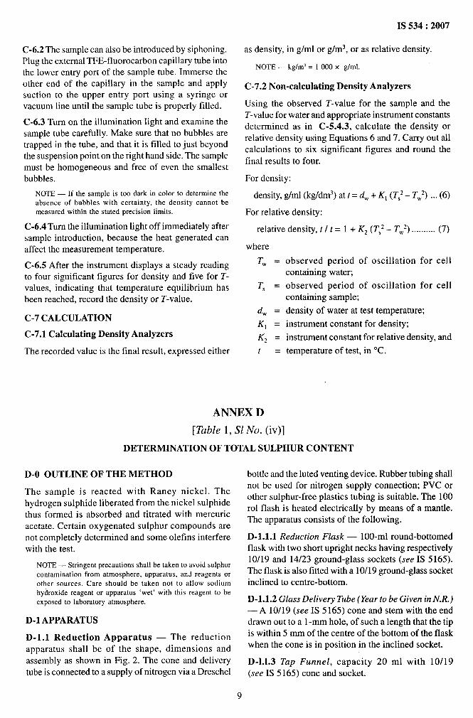
D-1.l Reduction Apparatus — The reduction
apparatus shall be of the shape, dimensions and
assembly as shown in Fig. 2. The cone and delivery
tube is connected to a supply of nitrogen via a Dreschel
bottle and the h.tted venting device. Rubber tubing shallnot be used for nitrogen supply connection; PVC orother sulphur-free plastics tubing is suitable. The 100rol flash is heated electrically by means of a mantle.The apparatus consists of the following.
D-1.l.l Reduction Flask — 100-ml round-bottomedflask with two short upright necks having respectively10/19 and 14/23 ground-glass sockets (see IS 5165).
The flask is also fitted with a 10/19 ground-glass socketinclined to centre-bottom.
D-1.1.2 Glass Delivery Tube (Year to be Given in N.R.)— A 10/19 (see IS 5165) cone and stem with the enddrawn out to a 1-mm hole, of such a length that the tipis within 5 mm of the centre of the bottom of the flaskwhen the cone is in position in the inclined socket.
D-1.1.3 Tap Funnel, capacity 20 ml with 10/19
(see IS 5 165) cone and socket.
9
IS 534:2007
D-1.1.4 Adaptor, right-angle connection with 10/ 19cone.
D-1.1.5 Condenser, a Liebig condenser, effective length150 mm, with a 14/23 cone and socket.
D-1.1.6 Absorber — A delivery tube of 6 t 0.5 mmouter diameter bent at 110° and containing a smallexpansion chamber in the upright section. The lowerend of the tube has a 1-mm hole, and fits into a covered200 mm x 32 mm outer diameter boiling tube. Theupper end of the delivery tube is bent at an angle of
70° and fitted with a 14/23 cone at a distance ofapproximately 135 mm from the longer arm.
D-1.1.7 Gas Washing Bottle, Dreschel bottle having adip-tube of about 6 mm outer diameter.
D-1.1.8 Microburette, capacity 10 ml arranged so that
the liquid in the absorber can be titrated. -
iTO LUTEOVENJING DEVICE
10
‘A’ /’FUNNEL
b10/19
D-1.2 Flask, a 500-ml stoppered conical flask, markedat the 400-ml level with the cone and stopper lubricatedwith silicone grease.
D-1.3 Measuring Cylinder, 10 ml capacity.
D-1.4 Pipette (not to be operated by mouth).
D-1.5 Thermometer, any suitable thermometerincluding the interval 75° to 80°C.
D-2 REAGENTS
D-2.1 Acetone
D-2.2 Propan-2-ol
D-2.3 Nitrogen
D-2.4 Raney Nickel, 50 percent nickel, 50 percentaluminium.
14/23
.
/
135mm
~CONOENSER
ABSORBER
\
f
OELIVERYTUBE
(J&Imm @ HOLE r
lL/2310/19
L
REOUCTIONFLASK
100mlREOUCTION
FLASK lmm.#. HOLE
FIG. 2 REDUCTIONAPPARATUS
10
IS 534:2007
D-2.5 Sodium Hydroxide Solutions, 2.5 N and 1 N— Clean the conical flask with nitric aci~potassiumbichromate mixture [prepared by dissolving 5 g ofpotassium bichromate in 5 ml of water and adding 100ml of concentrated (15 N) nitric acid, stirringcontinuously]; rinse thoroughly with water. Fill withwater to the 400-ml mark and add the mass of sodiumhydroxide pellets appropriate for preparation of the 2.5N or 1 N solution. Swirl gently until dissolution iscomplete and allow to cool.
D-2.6 Hydrochloric Acid, 5 N
D-2.7 Potassium Hydroxide, 40 g/1 solution in
ethandiol.
D-2.8 Mercuric Acetate Solution — Dissolve 0.675 g
of mercuric oxide, previously dried at 100”C, in 50 mlof water containing 2 ml of glacial (17 M) acetic acid.Dilute to 1000 ml with water and mix well. Dilute 50
ml of the solution thus prepared to 250 ml with waterand mix well. One millilitre of the diluted solution isequivalent to 0.02 mg of sulphur.
D-2.9 Dithizone Indicator Solution, 1 g/1 in acetone,prepared fresh daily, or every 3 days if stored in arefrigerator.
NOTE — When experience has been gained with theconcentrationof indicator required, a few grains of the solidindicator may be added to the absorber. In this way anyinstability of indicator solution is overcome.
D-3 PROCEDURE
D-3.1 Clean the apparatus thoroughly with a mixtureof nitric acid and potassium bichromate. Rinsethoroughly with water and acetone and dry in an ovenwhich has not been contaminated with sulphur orsulphur containing materials in previous use. Theapparatus is self scouring and, when in constant use,shall not be cleaned between determinations, exceptfor rinsing the flask, delivery tube, absorber and
thermometer with water. When not in constant use, itshall be cleaned between determinations with waterand acetone.
NOTE — For activating nickel perfectly, the weighed Raneynickel is kept in caustic solution for at least four hours.
D-3.2 Weigh accurately about 0.5 g of Raney nickel
and put it in the reduction flask using a cone madefrom glazed paper, and add 10 ml of sodium hydroxide
solution (2.5 N) from the measuring cylinder.
NOTE — Incrustations around the stoppers and necks ofsodium hydroxide bottles contain sufficient quantities ofsulphur to affect test results. Such incrustations should beremoved without allowing material to fall into the bottle. Beforeusing solution from tbe bottle, pour a little to waste. Replace
the stopper promptly.
Care shall be taken at this stage because there is avigorous reaction.
When the reaction has subsided, swirl the liquid in theflask to bring the nickel adhering to the sides of theflask to the bottom. Set the flask aside for 10 min andthen decant off the supernatant liquid. Wash down bothnecks of the flask with 10 to 15 ml of water. Swirl thewater vigorously to disturb the nickel residue, but avoidentrainment of air and, with minimum delay forsettling, decant off the water as completely as possiblewithout too much attention to removing the last drop.Repeat the water wash three times more, and followwith a wash with 10 ml of propan-2-ol. Decant mostof the propan-2-ol leaving enough to cover the catalyst,and add a further 10 ml of propan-2-ol.
D-3.3 Assemble the apparatus except for the tap funnel,lightly greasing all the joints with silicone grease. Add50 ml of a mixture of equal parts of sodium hydroxidesolution (1 N) and acetone to the boiling tube and add5 drops of the dithizone indicator solution.
D-3.3.1 Calculate the appropriate size of sample asfollows:
100 ml
Specified or expected sulphur content (mg/kg)
(with a maximum of 50 ml) and pipette this volumeinto the flask through the 10/1 9 socket.
D-3.4 Complete the assembly of the apparatus.Measure 10 ml of the hydrochloric acid solution into
the tap funnel. Pass nitrogen at the rate of 2 or 3bubbles/second as shown in the Dreschel bottlecontaining the ethane-di-ol potassium hydroxidesolution. Note the burette reading and titrate thecontents of the absorber with the mercuric acetatesolution to a pale pink colour.
D-3.4.1 Heat the flask at such a rate that the contents
boil gently in about 10 min. Maintain the heating for afurther period of 30 min at such a rate that smallbubbles rise copiously from the nickel and gentlerefluxing occurs.
D-3.4.2 Increase the input to the heating mantle slightly
and allow the hydrochloric acid solution to drip slowly(10 ml in 5 to 10 rein) into the “flask. Vigorousgeneration of hydrogen will occur, but little or nohydrogen sulphide will be evolved until about half the
hydrochloric acid has entered the flask. Titrate theabsorbing solution to a pink colour. As hydrogensulphide is evolved and ‘absorbed and the colour of theabsorbing solution reverts to yellow, titrate in moremercuric acetate solution in order to restore the pink
cblour. After the addition of the acid, open the tap ofthe funnel occasionally to sweep forward any hydrogen
sttlphide that may have collected below it. When theevolution of hydrogen sulphide has almost ceased,increase the nitrogen flow rate to about 5 bubbles/
11
IS 534:2007
second in the bottle to improve the transfer of hydrogensulphide to the absorber.
D-3.4.3 When the evolution of hydrogen sulphide hasapparently ceased, turn off the nitrogen temporarilyand cool the flask by reducing the heat input and byblowing a little air on to it or by applying a damp cloth.The reduction in pressure will cause the absorbingsolution to rise up the delivery tube. Restore thenitrogen flow before the absorbing solution reachesthe bend above the cone. Repeat this operation at about2 min intervals until no more hydrogen sulphide iswashed down. If any liquid enters the cone, the testshall be abandoned.
D-3.4.4 Boil the contents of the flask vigorously andcontinue the titration to the end point.
D-3.4.5 Carry out a blank test on the reagents omitting
the sample. Once a day is normally sufficient but theblank shall always be re-determined, if there is any
change in the reagents, apparatus or laboratoryatmosphere which could conceivably affect the blankvalue. This value should not exceed 0.6 ml.
D-4 CALCULATION
20 (y–v, )Total sulphur content, mg/kg =
Vx D
where
v, =
V2 =
v=
D=
volume of mercuric acetate solution used forthe sample titration, in ml;
volume of mercuric acetate solution used forthe blank test, in ml;
volume of sample taken for the test, in ml;
and
density of the sample at the temperature atwhich it was measured, in g/ml.
ANNEX E
[Table 1, S1No. (v)]
DETERMINATION OF DISTILLATION RANGE
E-1 OUTLINE OF THE METHOD
The distillation is carried out via a carefully controlleddistillation wherein temperature readings are noted forthe first drop of distillate and at the dry point.
E-2 APPARATUS
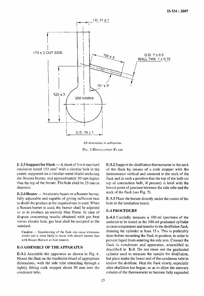
E-2.1 Flask — A standard 200-ml side-tube, heat-resistant glass distillation flask conforming to thefallowing dimensions (see Fig. 3):
Diameter of bulb, outside, mm : 76 Y1.5
~iameter of neck, inside, mm :21* I
Height of flask, outside, mm : 179*3
Vertical distance from bottom of : 120*3
bulb outside to bottom of vapour-tube opening in neck, mm
Length of side tube, mm : 100*3
Diameter of side tube, outside, mm : 7 & 0.5
Angle of wide tube with verticalaxis of bulb and neck : 75*3
E-2.2 Thermometer —A suitable thermometer having0.2°C subdivisions and covering the entire range may
be used.
E-2.3 Condenser — The condenser tube may consist
of a straight glass tube 600 to 610 mm in length and
12 mm in inside diameter, of standard wall thickness
(about 1.25 mm) with the exit end cut off square andground flat. It shall be set in a cooling trough so that at
least 380 mm of the tube is in contact with the water.
Clearance between the condenser tube and any parallel
side of the trough shall be not less than 19 mm. Thewater in the cooling trough shall be maintained at 10°
to 20”C. This may be done by adding ice to the water
or by circulating chilled water through the trough. Thetrough shall be so mounted that the condenser tube is
set at an angle of 75° with the vertical.
E-2.4 Receiver — A graduate of the cylindrical type,
of uniform diameter, with a pressed or moulded base
and a lipped top. The cylinder shall be graduated to
contain 100 ml, and the graduated portion shall be
neither less than 178 mm nor more than 203 mm in
length. It shall be graduated in single millilitres and
each fifth mark shall be distinguished by a longer line.
It shall be numbered from the bottom up at intervals
of 10 ml. The overall height of the graduate shall notbe less than 248 mm nor more than 260 mm. Thegraduations shall not be in error by more than 1 ml at
any point on the scale. The bottom 1 ml graduation
may be omitted.
12
IS 534:2007
179 f 3 OUT SIDE
‘/120k3
_/ I.D. 21 * 1
i 1/=/ —O.D. 7 * 0.5WALL THK. 1 * 0.15
—
f
4200 millilitre
—.
t
—
O.D. 76k 14 -
A!l dimensions in mi]limetres.
FIG. 3 DISTILLATIONFLASK
E-2,5 Support for Flask — A sheet of 3 to 6 mm hardinsulation board 152 mmz with a circular hole in the
center, supported on a circular metal shield enclosingthe Bunsen burner, and approximately 50 mm higher
than the top of the burner. The hole shall be 25 mm indiameter.
E-2.6 Heater — An electric heater or a Bunsen burner,fully adjustable and capable of giving sufficient heat
to distill the product at the required rate is used. Whena Bunsen burner is used, the burner shall be adjustedso as to produce an entirely blue flame. In case ofdispute concerning results obtained with gas heatversus electric heat, gas heat shall be accepted as the
standard.
Caution — Superheating of the flask can cause erroneousresults and is more likely to occur with electric heaters than
with Bunsen Burners as heat sources.
E-3 ASSEMBLY OF THE APPARATUS
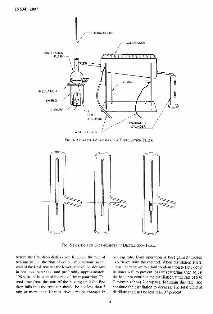
E-3.1 Assemble the apparatus as shown in Fig. 4.Mount the flask on the insulation board of appropriatedimensions, with the side tube extending through a
tightly fitting cork stopper about 50 mm into thecondenser tube.
E-3.2 Support the distillation thermometer in the neckof the flask by means of a cork stopper with thethermometer vertical and centered in the neck of theflask and in such a position that the top of the bulb (ortop of contraction bulb, if present) is level with thelowest point of juncture between the side tube and theneck of the flask (see Fig. 5).
E-3.3 Place the burner directly under the centre of thehole in the insulation board.
E-4 PROCEDURE
E-4.1 Carefully measure a 100-ml specimen of thematerial to be tested in the 100-ml graduated cylinder
at room temperature and transfer to the distillation flask,draining the cylinder at least 15 s. This is preferably
done before mounting the flask in position, in order toprevent liquid from entering the side arm. Connect theflask to condenser and apparatus, assembled as
described in E-3. Do not rinse out the graduatedcylinder used to measure the sample for distillation,but place under the lower end of the condenser tube toreceive the distillate. Heat the flask slowly, especially
after ebullition has begun, so as to allow the mercury
column of the thermometer to become fully expanded
13
IS 534:2007
kTHERMOMETER
r
CONDENSER
DISTILLATIONFLASK
7 ill?
/( I
11 ‘11111,;; I 11111;,1 I
INSULATION
SHIELD
BUR 2[STAND
WATER TUBES —y
FIG. 4 APPARATCJSASSEMBLYFORDISTILLATIONFLASK
FIG. 5 POSITIONOFTHERMOMETERIN DISTILLATIONFLASK
before the first drop distils over. Regulate the rate of heating rate. Even operation is best gained throughheating so that the ring of condensing vapour on the experience with the method. When distillation starts,wall of the flask reaches the lower edge of the side arm adjust the receiver to allow condensation to flow downin not less than 90 s, and preferably approximately its inner wall to prevent loss of spattering; then adjust120s, from the start of the rise of the vapour ring. The the heater to continue the distillation at the rate of 5 tototal time from the start of the heating until the first 7 ml/min (about 2 drops/s). Maintain this rate, anddrop falls into the receiver should be not less than 5 continue the distillation to dryness. The total yield ofmin or more than 10 min. Avoid major changes in distillate shall not be less than 97 percent.
14
IS 534:2007
E-4.2 Take the temperature reading when the firstdrop of distillate falls into the receiving cylinder andreport as the initial boiling point (IBP). Take a finalreading when the liquid just disappears from theflask, and report this reading as the dry pointtemperature.
E-4.3 Observe and record the following additional dataat the time and place of the distillation test:
a) Correction for inaccuracy of the thermometer,and
b) Barometer reading and temperature of thebarometer. The observed barometric pressureshall be corrected by reference to standardtables and reported in terms of millimetres ofmercury at O°C.
E-5 TEMPERATURE CORRECTIONS
E-5.1 Inaccuracy of Thermometer
This correction shall be obtained by calibration of the
thermometer used in the test and applied to theobserved thermometer reading.
E-5.2 Variation from Standard Barometric Pressure
This correction shall be applied to the observedtemperature after correcting for accuracy of thethermometer and is determined by the following equation:
C = [ 0.0427+ { 0.000 025X (760 - P))] X (760 -P)
where
C = the correction, in ‘C; andP = the measured barometric pressure, in
millilitres of mercury, corrected to O“C.
E-5.3 Combined Corrections
If the overall distillation range of the sample does not
exceed 2“C, a combined correction for thermometerinaccuracy and barometric pressure may be made onthe basis of the difference between the observed50 percent boiling point and the true boiling point at760 mm of benzene, that is, 80. l“C.
ANNEX F
[Table 1, S/ No. (viii)]
DETERMINATION OF BROMINE INDEX
F-1 OUTLINE OF THE METHOD
The specimen is added to a solvent and titrated withelectrolytically generated bromine at roomtemperature. The end point is determined by a deadstop method. The time of titration is proportional to
the bromine added to the specimen.
F-2 APPARATUS
F-2.1 Amperometric — Coulometric Apparatus
ltis an automatic apparatus, suitable for bromine index
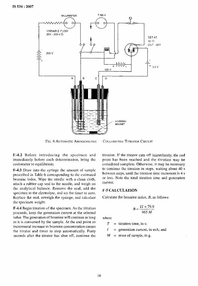
titrations with variable generator current and timer. Atypical circuit diagram of suitable equipment is shownin Fig. 6.
F-2.2 Syringe, 2 ml with needle and rubber cap seal.
F-2.3 Stirrer, magnelic.
F-3 REAGENTS
F-3.1 Electrolyte — To lnake 1 Iitre, mix 600 ml of
glacial acetic acid, 260 ml of absolute methanol, and140 ml of potassium bromide solution (119 g/1).Dissolve 2 g of mercuric acetate in this mixture.
F-3.2 Potassium Bromide Solution (119 g/1) —Dissolve 119 g of potassium bromide (KBr) in water
and dilute to one litre.
F-4 PROCEDURE
F-4.1 Place 50 ml of electrolyte in a clean, dry titration
cell, insert the electrodes, and begin stirring. Applythe generation current in accordance with Table 6.
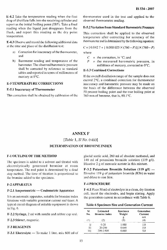
Table 6 Specimen Size and Generation Current
S1 Estimated Specimen GenerationNo. Bromine Index Weight Current
MA(1) (2) (:) (4)
i) 0-20 1.000 1,0ii) 20-200 0.600 5.0
iii) 200-2000 0.060 5.0
15
IS 534:2007
MILLIMETER TIMER
mrlr
SET AT
10 (2
CUT OFF
STIRRINGMAGNET
FIG. 6 AUTOMATICAMPEROMETRIC— COULOMETRICTITRATORCIRCUIT
F-4.2 Before introducing the specimen andimmediately before each determination, bring thecoulometer to equilibrium.
F-4.3 Draw into the syringe the amount of sampleprescribed in Table 6 corresponding to the estimatedbromine index. Wipe the needle with a clean cloth,attach a rubber cap seal to the needle, and weigh onthe analytical balance. Remove the seal, add thespecimen to the electrolyte, and set the timer to zero.Replace the seal, reweigh the syringe, and calculatethe specimen weight.
F-4.4 Begin titration of the specimen. As the titrationproceeds, keep the generation current at the selectedvalue. The generation of bromine will continue as longas it is consumed by the sample. At the end point anincremental increase in bromine concentration causesthe titrator and timer to stop automatically. Forty
seconds after the titrator has shut off, continue the
titration. If the titrator cuts off immediately, the endpoint has been reached and the titration may beconsidered complete. Otherwise, it may be necessaryto continue the titration in steps, waiting about 40 sbetween steps, until the titration time increment is 4 sor less. Note the total titration time and generation
current.
F-5 CALCULATION
Calculate the bromine index, B, as follows:
B=TI X 79.9
965 h’
where
T = titration time, in s;
I = generation current, in mA; and
M = mass of sample, in g.
16
IS 534:2007
ANNEX G
[Table 1, S1 No, (ix)]
DETERMINATION OF SOLIDIFICATION POINT
G-1 OUTLINE OF THE METHOD
Solidification point is measured by noting themaximum temperature reached during a controlledcooling cycle after the appearance of a solid phase.
G-2 APPARATUS
G-2.1 Benzene Container, air jacketed.
G-2.1.1 Inner Container, a test tube 15 mm in outsidediameter and 125 mm in Iength.
G-2.1.2 Air Jacket, a standard test tube 25 mm inoutside diameter and 150 mm in length.
G-2.1.3 Insulation, with dry absorbent cotton or glasswool.
G-2.2 Benzene Container (Thick Walled), a glass testtube 18 mm in outside diameter, 14 mm in insidediameter and 150 mm in length.
G-2.3 Ice Bath, a one litre beaker or similar suitablecontainer having an effective depth of at least 127 mmand filled with chipped or shaved ice.
G-2.4 Stirrer, consisting of a 1-mm wire (copper orstainless steel) or a 2-mm glass rod with one end bentinto a circular form at right angles to the shaft so thatit will move freely in the annular space between thethermometer ktem and the wall of the smaller test tube.
G-2.5 Temperature Measurement Device,, eitherdevice described below has been found satisfactory.
G-2.5.1 Thermometer, Benzene freezing pointthermometer having a range from 4.0 to 6.0°C and least
count of O.OI°C and conforming to the followingrequirements:
Name — Solidification Point of Benzene
Reference Fig. No. — 10
Range, “C — 4t06a) Immersion — Total
Graduations, ‘C:Subdivisions — 0.02
Long lines at each — 0.1
Numbers at each — 0.02
Scale error, Max — 0.04
Expansion chamber:
Permit heating to — 50°ca) Total length, mm — 210 to 220
b) Stem OD, mm — 6.0 to 7.0
c) Bulb length, mm — 25 to 35
d) Bulb OD, mm — 6,0 to > stem
Scale location:
Bottom of the bulb to line at — 4°Ca) Distance, mm — llotol15
b) Length of graduated — 45 to 75portion, mm
G-2.5.2 Thermistor — ~pe CSP, with accuracy of0.01 “C with a nominal resistance at 2500$2 at 25°C.The thermistor shall be equipped with an ohmmeter
capable of reading resistance to the nearest 0.1 Q.
G-2.6 Stirring Apparatus (Optional) — Theapparatus may be an acceptable replacement formanually stirring the benzene solution.
G-3 PREPARATION OF APPARATUS
G-3.1 Fit the benzene container with a two-hole corkstopper. Through one hole insert the temperaturemeasurement device. The thermometer should beinserted up to the 4.0°C mark. The thermistor should
be inserted so as to contact the benzene solution.Through the other hole insert shaft of the stirrer,
G-3.2 If using the benzene container (air jacketed), placea 3.2-mm layer of dry absorbent cotton or glass wool inthe bottom of the larger test tube and insert the innercontainer up to the lip into a cork stopper or annularring of cork that just fits into the mouth of the air jacket.
G-4 PROCEDURE
G-4.1 Saturate the sample of benzene with water byplacing 7 to 8 ml of the sample in the benzene container,add one drop of water, and shake the tube and contentsvigorously.
G-4.2 Place the cork stopper onto the benzene containerand onto the stirring apparatus, if available.
G-4.3 When using the benzene container (air jacket),the operator may cool the smaller test tube and contentsrapidly to about 6°C in the ice bath, while stirring. Wipe
dry the outside of the smaller test tube and insert itinto the larger test tube, Place the assembled test tubesin the ice bath.
G-4.4 Stir the benzene continuously and observe thethermometer reading closely. The temperature willfall to a minimum, then rise to a maximum, remain
constant at this maximum for approximately 15s, andthen fall again (see Note 1). The minimum
temperature is due to super-cooling before
17
IS 534:2007
solidification starts and shall not be more than 0.7°Cbelow the maximum. Record the maximum constanttemperature observed to the nearest 0.01 “C anddesignate it as ‘wet’ (see Note 2).
NOTES
1 If distinct minimum and maximum points are not evident, orif the temperature does not remain constant at the maximumfor at least 15 s, the determination shall be repeated.
2 The precision can be increased to *0.OI°C by using amagnifying glass that ensures a reading perpendicular to thestem of the thermometer. In such cases it may be necessary tocorrect for stem exposure, that under ordinary conditions thiscorrection will be less than 0.01 ‘C.
G-5 EXPRESSION OF RESULTS
Results shall be reported on the anhydrous basis. Sincethe determination is actually made on water-saturatedbenzene, the solidification point shall be corrected tothe anhydrous basis by adding 0.09°C to the observedmaximum temperature following the minimumcorrections for the accuracy of the thermometer shallbe made.
G-6 PRECISION
Duplicate determinations on the same sample shall notdiffer by more than 0.02°C (see G-4.4, Note 2).
ANNEX H
[Table 1, S1 No. (x)]
DETERMINATION OF THIOPHENE
H-1 OUTLINE OF THE METHOD
Thiophene is reacted with isatin, under prescribed
conditions, to form a coloured compound. Thecompound is extracted into sulphuric acid, and theintensity of the colour is measured spectrophoto-metrically, Thiophene concentration is obtained by
correlation with known concentration of samples.
H-2 APPARATUS
H-2.1 Separator Funnels, 50,250, 500, and 1000ml, glass-stoppered.
H-2.2 Spectrophotometer — Any spectrophotometermay be used that is capable of repeatability of 0.005absorbance units in the range from 0.1 to 1.4
absorbance and repeatability of wavelength of 1 nm inthe region from 400 to 700 nm.
H-2.3 Absorption Cells, 1 cm, matched, glass or silica.
H-2.4 Analytical Balance
H-2.5 Pipettes, 1,2, 5 and 10 ml.
H-2.6 Graduated Cylinders, 250 and 1000 ml.
H-2.7 Volumetric Flasks, glass-stoppered, 50, 100,250 and 1000 ml.
H-2.8 Filter Paper, medium filter (Whatman 1) andrapid hardened (Whatman 54).
18
H-3 REAGENTS
H-3.1 Cadmium Chloride Solution (20 g/1) —Dissolve 20 g of anhydrous cadmium chloride
(CdCIJ or 25 g of cadmium chloride hydrate(CdC12.21/2HaO) in 200 ml of water and dilute toone Iitre.
H-3.2 Sulphuric Acid (sp gr 1.84), concentrated.
H-3.3 Benzene, Thiophene, free.
H-3.3.1 Wash 700 ml of benzene in a 1 000-ml
separator funnel with successive 100-ml portions ofconcentrated sulphuric acid (HZSOJ to which has beenadded 5 ml of isatin solution, until the H2S01 layer islight yellow or colorless. Wash the benzene with 100ml of water and then twice with 100 ml of cadmium
chloride solution (CdCIJ. Finally, wash with another100-ml portion of water. Filter the benzene throughmedium filter paper into a storage bottle and tightlystopper.
H-3,3.2 Prepare 1400 ml of thiophene-free benzene.Measure the absorbance of this material by theprocedure outlined in H-5.2 and H-6.2.The absorbance
should be not greater than 0.01.
H-3.4 Ferric Sulphate-Sulphuric Acid Solution —
Add 0.2 g of ferric sulphate (Fez(SOJJ.9H20) togetherwith 38 ml of water to a 1-litre volumetric flask. Swirlto dissolve. Cautiously add about 100 ml of H2SOd
IS 534:2007
and swirl. Allow time for the heat of reaction to subside Dilute to volume with thiophene-free benzene and mix.and dilute to volume with HzSOd. This is Solution 1. Pipette 1 ml of Solution 1 into a
Caution — Protective clothing and goggles should be wornwhenever HzSOdis used,
H-3.5 Isatin-Chloroform-Benzene Solution — Add0.5 g of isatin to 200 ml of chloroform. Heat, in a fumehood, to a temperature just below the boiling point(61 ‘C) of chloroform and maintain for 5 min withstirring. Filter into a 250-ml volumetric flask throughhardened rapid filter paper. Wash the filter paper withtwo 20-ml portions of thiophene-free benzene(see H-3.3) eluting the washings into the volumetricflask. Dilute to volume with thiophene-free benzene.
H-3,6 Thiophene
H-4 PREPARATION OF REAGENT BLANKSAND SAMPLE BLANK
H-4.1 Reagent Blank 1 — To a 50-ml separatorfunnel pipette 5 ml of isatin solution and 10 ml offerric sulphate-sulphuric acid solution. Stopper and
shake for 2 min f 15 s. The shaking is accomplishedby wrist action in a rocking motion through a 180°
arc roughly once each second. Allow the two phasesto separate and draw off the lower HZSO1 layer into a
50-ml volumetric flask. Add 10 ml of H2SOa to theseparator funnel, stopper, and shake for 30 * 5 s.Again draw off the lower HJO~ layer into the 50-mlvolumetric flask containing the first extract. Dilute
to volume with H2SO~ and mix. This blank is stablefor 8 h and need not be repeated with each analysisduring this period.
H-4.2 Reagent Blank 2 — Into a 50-ml volumetricflask, pipette 10 ml of ferric sulphate-sulphuric acidsolution and dilute to volume with HZSOA.Stopper andmix. This blank is stable for 8 h and need not berepeated with each analysis during this period.
H-4.3 Sample Blank — Take a 100-ml portion of the
CdC12 washed and filtered benzene sample (prepared in
accordance with the procedure in H-6.1). Transfer to a250-ml separator funnel. Add 10 ml of ferric sulphate-sulphuric acid solution, stopper, and shake for 2 min f15 s. Allow the two phases to separate and draw off thelower HzSO, layer into a 50-ml volumetric flask. Add10 ml of H2SOq to the separator funnel and shake for30 t 5 s. Again draw off the lower H2SOa layer into the
50-ml volumetric flask containing the first extract. Diluteto volume and mix. Repeat with each specimen.
H-5 PREPARATION OF CALIBRATIONCURVES
H-5.1 Add approximately 0.2 g of thiophene, weighedto the nearest 0.0002 g to a 100-ml volumetric flaskcontaining about 50 ml of thiophene-free benzene.
100-ml volumetric flask, dilute to volume withthiophene-free benzene, stopper, and mix. This isSolution 2 and will contain approximately 20 mg ofthiophene per millilitre.
H-5.2 Pipette O, 1,2,5,7, and 10 ml of Solution 2 into100-ml volumetric flasks and dilute to volume withthiophene-free benzene. Transfer to 500-ml separatorfunnels and follow the procedure in H-6.2 and H-6.3for each concentration. Plot absorbance versusconcentration, in microgram per millilitre.
H-5.3 Prepare Solution 3 containing approximately 40pg of thiophene per millilitre by pipetting 2 ml of
Solution 1 into a 100-ml volumetric flask and dilutingto volume with thiophene-free benzene. Follow theprocedure in H-5.2 to obtain the calibration curve for50-ml specimens.
H-6 PROCEDURE
H-6.1 To a 500-ml separator funnel, add 250 ml of
sample and 40 ml of cadmium chloride solution. Stopperand shake for approximately 30 s. Allow to settle and
discard the aqueous layer. Filter the benzene layerthrough medium filter paper into a 250-ml graduated
cylinder. Part of the filtered benzene is to be used forthe sample blank. Proceed with preparation of the sample
blank as described in H-4.3. From the remaining filteredbenzene, transfer 100 ml to 250-ml separator funnel.
H-6.2 To the separator funnel add 5 ml of isatin
solution and 10 ml of ferric sulphate-sulphuric acidsolution. Stopper and shake for 2 min * 15 s. Allowthe phases to separate and draw off the lower H2SOdlayer into a 50-ml volumetric flask. Add 10 ml ofHJOA to the separator funnel, stopper, and shake for30 ~ 5 s. Again draw off the lower H#OA layer into
the 50-ml volumetric flask containing the first extract.Dilute to volume with H2SOd and mix.
H-6.3 Measure the absorbance of this material at 589nm in a 1 cm cell versus Reagent Blank 1 (see H-4.1)in a matched 1-cm cell. Instrument conditions shouldbe identical with those employed during calibration.
H-6.4 Determine the concentration of thiophene from
the calibration curve (see H-5). If the absorbance isgreater than 1.5, repeat the procedure using a 50-mlspecimen instead of 100 ml. If the 50-ml specimenstill gives absorbance above 1.5, then the specimenmust be diluted with thiophene-free benzene beforeproceeding.
H-6.5 Determine the absorbance of the sample blank
(see H’-4.3) at 589 nm using Reagent Blank 2(see H-4.2) as reference. Determine the apparent
concentration of thiophene in the sample blank.
19
IS 534:2007
H-7 CALCULATION
Calculate the thiophene content of the sample inB=
milligrams per kilogram as follows:
Thiophene, mg/kg = (A - B) F/dF=
where
A = thiophene for sample determined fromd =
appropriate calibration curve (see Table 7),~glml;apparent thiophene ‘determined for sampleblank from appropriate calibration curve(see Table 7), pg/ml;dilution factor of sample; and
density of benzene at the temperature of thesample.
Table 7 Calculation Factors
SI Designation of Cell SolutionsNo. Equation of - ~ \
H-7 Solutionof Sample Versus Solution of Reference(1) (2) (3) (4)
O A H2S0,.Fe2(S0,),; isatin after contact with sample (see H-6.2) Reagent blank 1 (see H-4.1) @ii) B Sample blank (see H-4.3) Reagentblank2 (seeH-4.2)
ANNEX J
[Table 1, S1 No. (xi)]
DETERMINATION OF ACID WASH COLOUR
J-1 OUTLINE OF THE METHOD
A mixture of the aromatic hydrocarbon and sulphuricacid is vigorously shaken and the colour of the acidlayer is compared with that of colour standardsprepared from COCIZand FeCl~.
J-2 APPARATUS
J-2.1 Containers for Colour Standards — Clear and
unblemished, clean, French square, flint glass, flat-bottom, glass-stoppered, 1-OZcapacity bottles holding
31 to 33 ml when filled to the neck. The bottles shallbe numbered consecutively from O to 14.
J-2.2 Test Containers — Containers exactly likedescribed in J-2.1 except that each French squarebottle shall be marked by etching to show when thebottle contains the volume of 7 and 28 ml, respectively.
Coloured crayons and similar markers shall not be usedfor marking the bottles.
J-3 REAGENTS
J-3.1 Hydrochloric Acid (1 + 39), mix 25 ml ofhydrochloric acid (31 percent by mass, HC1) with975 ml of water.
J-4 PREPARATION OF REFERENCE COLOURSTANDARDS
J-4.1 Stock Solutions
Prepare the following basic reagent solutions for usein preparing the reference colour standard.
J-4.1.1 SohztkwzA — Dissolve 59.50 g of CoCIJ.6Hz0in HCI and make up to one litre in a volumetric flask
with HC1.
J-4.1.2 Solution B — Dissolve 45.054 g of FeCl~.6Hz0
in HC1 and make up to one Iitre in a volumetric flaskwith HC1,
J-4.1.3 Solulion C — Mix 3 % volumes of Solution Awith 36 y2 volumes of Solution B and dilute with 90volumes of water.
J-4.1.4 Solution D — Mix 3 % volumes of Solution Awith 36 % volumes of Solution B.
J-4.1.5 Solution E — Prepare an aqueous solution ofKzCr20q saturatedat21 “C.
J-4.1.6 Solution F — Prepare an aqueous solution of
KzCrz07 saturated at 21 “C and dilute with an equalvolume of water.
20
IS 534:2007 ‘
J-4.2 Prepare reference colour standard solutionshaving the following compositions and numbered fromo to 14:
No. O -
No. 1 –
No. 2 –
No. 3 –
No. 4 –
No. 5 -
No. 6 -
No. 7 -
No. 8 -
No. 9 -
No. 10-
No. 11 -
No. 12-
No. 13–
No. 14-
Distilled water.
1 volume of Solution C plus 1 volumeof water.
5 Y2 volumes of Solution C plus 2volumes of water.
Solution C.
1 volume of Solution D plus 1 volumeof water.
5 Y2 volumes of Solution D plus 2
volumes of water.
Solution D.
5 volumes of Solution E plus 2 volumesof water.
Solution E.
7 volumes of Solution E plus ~z volumeof Solution F.
6 % volumes of Solution E plus 1
volume of Solution F.
5 Y2 volumes of Solution E plus 2
volumes of Solution F.
1 volume of Solution E plus 1 volumeof Solution F.
2 volumes of Solution E plus 5 volumesof Solution F.
Solution F.
J-4.3 Rinse the No. Ocontainer (see J-2.1) and its glassstopper three times with water, fill with water, andstopper. Rinse the No. 1 container and its stopper threetimes with reference colour standard solution No. 1
(see J-4.2), fill with this solution, and stopper. In thisway, prepare the set of containers of colour standards
from O to 14 having the compositions shown for thecorresponding colour solution standards in J-4.2.
When filling the French square bottles, leave 6 mm ofvapour space below the neck of the bottle. Seal each
container with paraffin to prevent loss by evaporationor seepage.
J-5 PROCEDURE
J-5.1 Rinse a test container (see J-2.1) twice with acidof the strength specified in Table 8 for the type ofsample to be tested (see Note 1). Drain the rinsingsand fill with the acid up to the 7-ml mark. Add sufficientsample to bring the total volume to the 28-ml mark
(see Note 2). Insert the stopper, hold a finger over thestopper, and give vigorous shakes with a stroke of 13to 25 cm, shaking for a total of 150 cycles over a period
of 40 to 50 s, that is at a rate of 3 to 3.75 cyclesls.
NOTES
1 Concentrated sulpburic acid will cause severe burns on
21
contact with the skin. As a precaution the test container shouldbe wrapped in a towel or enclosed in a plastic bag during theshaking period.
2 If the room tempemture is above 29”C, maintain the acid,sample, and reference colour standards at a temperaturebetween 25°C and 29°C through the test, and insulate the testcontainer in some convenient way, such as wrapping with acloth, during the shaking period.
J-5.2 Allow the container to stand protected fromiirect sunlight, for the period of time shown in Table 8.Without further delay invert the container gently onceor twice to obtain a uniform colour in the acid layer,
md compare the colour of the acid layer with that ofthe standards (see J-4.3). Make the comparison againsta white background or against daylight, usingtransmitted light (see Note). When testing samples inGroup 1 (see Table 8), observe the colour of the oillayer as well as that of the acid layer.
NOTE — Agreement of results may be improved by using acolour comparator of a suitable type for observing the colourof the acid layer in comparison with tbe reference standard
colour solatiorr.
J-5.3 Designate the colour of the acid layer by thenumber of the nearest matching standard, following
the number with a plus or minus sign if the sample isdarker or lighter, respectively, than the standard.Disregard any difference in hue and determine onlywhether the colour of the acid layer is darker or lighterthan the colour of the reference standard to which thesample most nearly corresponds. If the hue of the acid
colour is different from the hue of the reference colourstandard, record the colour number followed by (X).Thus ‘No. 4 – (X)’ means that the acid wash test colouris slightly lighter than No. 4 colour standard and that
the hue of the No. 4 colour standard is not the same asthe hue of the acid layer.
J-6 INTERPRETATION OF RESULTS
J-6.1 Report sample (see Table 8) as passing the testonly when the oil layer shows no change in colour andwhen the acid layer is not darker than the specified
colour standard.
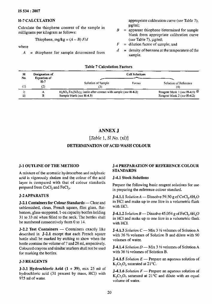
Table 8 Acid Strength and Standing Times
(Clauses J-5, 1, J-5.2 and J-6.1)
Sample Acid StandingStrength TimePercent min
(1) (2) (3)—
Benzene, Toluene, Xylene 96 15
(except Xylene, industrialgrade), Any other mosthighly refined products
J-6.2 A cloudiness of haze in the oil layer should notbe interpreted as a change in colour.
IS 534:2007
ANNEX K
[Table 1, S1 No. (xii)]
DETERMINATION OF N-FORMYLMORPHINE AS NITROGEN
K-1 OUTLINE OF THE METHOD
The sample of liquid petroleum hydrocarbon is injectedinto a stream of inert gas (helium or argon). The sampleis vaporized and carried to a high temperature zonewhere oxygen is introduced and organic and boundnitrogen is converted to nitric oxide (NO). The NOcontacts ozone and is converted to excited nitrogenoxide (N02). The light emitted as the excited NOZdecays is detected by a photomultiplier tube and theresulting signal is. a measure of the nitrogen containedin the sample.
K-2 APPARATUS
K-2.1 Furnace, Electric — Electric furnace held at a
temperature sufficient to volatilize and pyrolyze theentire sample and oxidize the organically boundnitrogen to NO. Furnace temperature(s) for petroleum
substances shall be as recommended by themanufacturer.
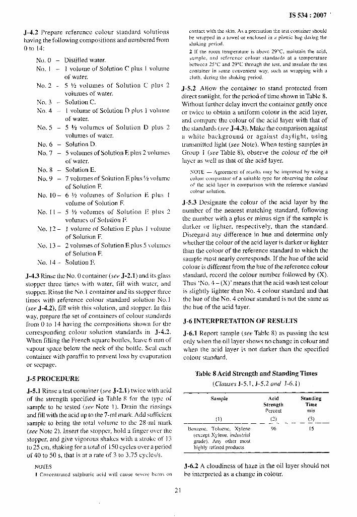
K-2.2 Combustion Tube, fabricated from quartz isrequired. The inlet end of the tube holds a septum forsyringe entry of the sample and has a side arm forintroduction of oxygen (02) and inert gas. The
construction is such that the inert gas sweeps the inletzone transporting the entire volatilized sample into a hightemperature oxidation zone. The oxidation section shallbe large enough (Fig. 7 and Fig. 8) to ensure completeoxidation of the sample. Fig. 7 and Fig. 8 depict
conventional pyrolysis tubes. Other configurations areacceptable, if precision is not degraded.
K-2.3 Drier ‘Ihbe — The reaction products include
water vapour that must be eliminated prior tomeasurement by the detector. This can be accomplishedwith a magnesium perchlorate Mg(CIO& scrubber or
a membrane drying tube (permeation drier), or both.
K-2.4 Chemiluminescent Detector, capable ofmeasuring light emitted from the reaction between NOand ozone.
K-2.5 Totalizer, having variable attenuation, andcapable of measuring, amplifying and integrating thecurrent from the chemiluminescent detector. Theamplified or integrated output signal shall be appliedto a digital display and to strip chart recorder, if desired.
K-2.6 Microlitre Syringe, of 5, 10,25, 50, or 250 @
capacity capable of accurately delivering microlitrequantities is required. The needle should be longenough to reach the hottest portion of inlet sectionfurnace when injecting the sample.
K-2.7 Recorder (Optional)
K-2.8 Constant Rate Injector System (Optional),
capable of delivering a sample at a precisely controlledrate and may have independent signal processing anddata display capabilities (optional).
K-2.9 Boat Inlet System (Optional), to facilitate
analysis of samples that would react with the syringeor syringe needle. Pyrolysis tube for boat inlet use mayrequire specific construction permitting insertion of aboat fully into the inlet furnace section.
K-2.1O Outlet End of Pyrolysis Tube (Optional) —It maybe constructed to hold a removable quartz inserttube.
FTHE MANUFACTURER OF THISSEPARATE OF THIS TUBECONFIGURATION RECOMMENDS
\
USE OF A QUARTZ INSERT TUBEPACKED WITH CUO.
/“-
02 INLET PORT
I Ezd l__J 230
INLET PORT
1- 410. IAll dimensions in millimetres.
FIG. 7 QUARTZ PYROLYSIS TUBE
22
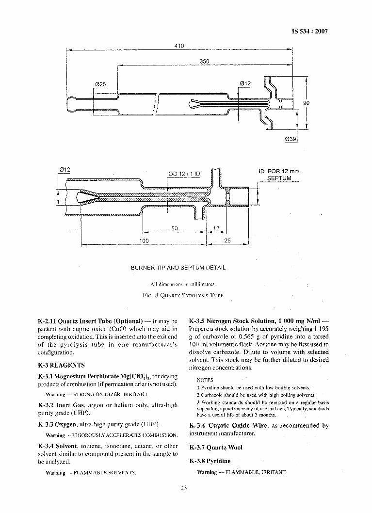
1S 534:2007
410 *
I
350
—
i90
ID FOR 12 mm
SEPTUM
L 50 12.—-
100 25. &—
BURNER TIP AND SEPTUM DETAIL
AII dimensions in mi!lirnetres.
FIG. 8 QUARTZ PYROLYSIS TUBE
K-2.11 Quartz Insert Tube (Optional) — It may bepacked with cupric oxide (CUO) which may aid incompleting oxidation. This is inserted into the exit endof the pyrolysis tube in one manufilcturcr’sconfiguration.
K-3 REAGENTS
K-3.1 Magnesium Perchlorate Mg(CIOJz, for dryingproducts of combustion (if permeation drier is not used).
Warning — STRONG OXIDIZER, IRRITANT.
K-3.2 Inert Gas, argon or helium only, ultra-higl}purity grade (UHP).
K-3.3 Oxygen, ultra-high purity grade (UHP).
Warning — VIGOROUSLY ACCELERATES CO.MBIJSTION.
K-3.4 Solvent, toluene, isooctane, cetane, or othersolvent similar to compound present in the sample tobe analyzed.
Warning — FLAMMABLE SOLVENTS.
K-3.5 Nitrogen Stock Solution, 1000 mg N/ml —Prepare a stock solution by accurately weighing 1.195g of carbazole or 0.565 g of pyridine into a tarredi00-ml v{>lumetricflask. Acetone maybe first used todissolve carbazole. Dilute to volume with selectedsolvent. This stock may be further diluted to desirednitrogen concentrations.
NOTES
1 Pyridine should be used with low boiling solvents.
2 Carbazole should be used with high boiling solvents.
3 Working standards should be remixed on a regular basisdepending upon frequency of use and age. Typically, standardshave a useful Iifc of about 3 months.
K-3.6 Cupric Oxide Wire, as recommended byinstrument manufacturer.
K-3.7 Quartz Wool
K-3.8 Pyridine
Warning — FLAMMABLE, IRRITANT.
23
IS 534:2007
K-3.9 Carbazole
K-3.1O Acetone
warning — FLAMMABLE,
K-4 PREPARATION OF APPARATUS
K-4.1 Assemble apparatus in accordance withmanufacturer’s instructions.
K-4.2 Adjust the gas flows and the pyrolysistemperature to the desired operation conditions. Theinlet temperature will depend upon which inlet method
is used (see K-2.2 and K-2.9).
K-5 CALIBRATION AND STANDARDIZATION
K-5.1 Prepare a series of calibration standards usinga stock solution covering the range of operation andconsisting of nitrogen type and matrix similar tosamples to be analyzed.
K-5.2 Volumetric measurement of the injected sample
can be obtained by filling the syringe to the 80 percentlevel, retracting the plunger so that the lower liquidmeniscus falls on the 10 percent scale mark, andrecording volume of liquid in the syringe. After the
sample has been injected, again retract the plunger sothat the lower liquid meniscus falls on the 10 percentscale mark, and record the volume of liquid in thesyringe. The difference between the two volumereadings is the volume of sample injected.
K-5.3 Alternatively, the sample injection device maybe weighed before and after injection to determine theamount of sample injected. This test method providesgreater precision than the volume delivery method,provided a balance with a precision of +0.01 mg is used.
K-5.4 Insert the syringe needle through the inletseptum up to the syringe barrel and inject the sampleor standard at a uniform rate of 0.2 to 1.0 pi/s. Rate ofinjection is dependent on such factors as viscosity,hydrocarbon type and nitrogen concentration. Each
user must adopt a method whereby a consistent anduniform injection rate is ensured.
K-5.5 For the method blank, rinse the syringethoroughly with the solvent blank. Then inject the sameamount of solvent blank as utilized with standards and
obtain the reading. Measure the blank a second timeand average the results. The solvent blank shouldcontain less than 1 mg/kg of nitrogen.
K-5.6 If the system features a totalizer with calibrationadjust, repeat the measurement of each calibrationstandard three times. The average of the three resultsshall be adjusted with the calibration setting to this
average. System performance shall be checked with
suitable calibration standard each day and whenchanging concentration ranges.
K-5.7 For those detectors not equipped with acalibration adjust, construct a standard curve as follows:
Repeat the determination of each calibrationstandard and the blank three times to determine theaverage net response for each standard. Construct acurve plotting of milligrams of nitrogen injectedversus detector response (integration count). Theresponse curve should be linear and shall be checkedat least once per week.
K-6 PROCEDURE
K-6.1 Sample sizes ranging from 3 to 40 pl areacceptable. It is advisable that the size of injected
sample shall be similar to the size of injectedstandard.
K-6.2 Flush the microlitre syringe several times withthe unknown sample. Determine the sample size asdescribed in K-5.4.
K-6.3 Experience dictates the best sensitivity setting
and sample size. Typical sample sizes have been givenin Table 9.
Table 9 ~pical Sample Sizes
s] Nitrogen Sample SizeNo. mg/kg ~1
(1) (2) (3)
O 51 up to 40ii) 10 UP to 8
iii) 100 up to 8iv) >100 Dilutesampleto most
convenientlevel
K-7 CALCULATION
K-7.1 For analyzers equipped with a calibration adjust,calculate the nitrogen content of the sample parts permillion (mg/kg) by mass as follows:
Nitrogen, mg/kg = (1 – B) X K/(V X D)
Nitrogen, mg/kg = (1 – B) X K/Al
where
D = density of sample, in g/ml;
K = dilution factor;
V = volume of sample, in ml;
M = mass of sample, in mg;
I = visual display readings of sample, in mg N;
and
B = average of visual display readings of blank,
in mg N.
K-7.2 For analyzers not equipped with calibration
adjust, calculate the milligrams per kilograms by massnitrogen as follows:
Nitrogen, mg/kg = 1 X S X K/(V X D)
24
IS 534:2007
where V = volume ofsample, inj.d;
D = density of sample, in g/ml; I = detector response, integration counts; and
S = slope of standard curve, in mg N/COLIIIt; K = dilution factor (when applicable).
ANNEX L
[Table 1, S1 No. (xiv)]
DETERMINATION OF CARBON DISULPHIDE
L-1 OUTLINE OF THE METHOD
Under specified conditions diethylamine-cupric acetatereagent reacts with carbon disulfide to produce theyellow-orange color of cupric diethyl-dithiocarbomate.The intensity of the color produced is measured bymeans of a spectrophotometer.
(CJ+,),NH + CS2 -+ (C2HJ2 NCSSH(diethyldithiocarbamic acid)
2(C2H5)2NCSSH+ Cu (C#I@J* + [(CZHS)ZNCSSIZ
CU+2CH3COOH
L-2 APPARATUS
L-2.1 Spectrophotometer, suitable for measurementsat 430 nm with a band width not greater than 35 nm.
L-2.2 Cells, 5 cm, chemically resistant glass.
L-2.3 Weighing Bulbs, eitfier as prepared in thelaboratory or commercially supplied.
L-2.4 Mohr Pipette, 5 ml equipped with suction bulb.
L-3 REAGENTS AND MATERIALS
L-3.1 Benzene (Carbon Disulphide-Free)—Toa21separator funnel add 1000 ml of benzene and 200 mlof alcoholic sodium hydroxide (NaOH) and shake well.
Allow to stand for 1 h, shaking at 15 min intervals.Draw off and discard the lower layer. Wash 4 timesusing 300 ml of water each time, and drawing off anddiscarding the water (lower) layer after each washing.Filter the treated benzene through dry filter paper intoa 1-litre glass stoppered bottle. Check the treatedbenzene for the presence of carbon disulphide asdescribed in L-5, If carbon disulfide is present, repeatthe benzene purification given above. Carbon disulfide-
free benzene will not undergo further diminution in
absorbance at 430 nm when it has been thus retreated.
L-3.2 Carbon Disulfide (CSZ)
L-3.3 Cupric Acetate in Methanol — Add 1.0 +0.001 g of cupric acetate monohydrate, powdered,
neutral crystals to a 1 000-ml glass -stopperedvolumetric flask containing approximately 600 ml ofmethanol. Shake to dissolve, Dilute the contents tovolume with methanol and mix thoroughly. This
reagent should be prepared fresh, each month, orsooner if appreciable amounts of copper salts separatefrom the solution.
L-3.4 Diethylamine-Cupric Acetate Reagent —Using a Mohr pipette, add 2.5 ml of diethylamine toapproximately 50 ml of carbon disulfide-free benzenecontained in a 100-ml glass-stoppered volumetric flask,Using a graduated cylinder, add 20 ml of cupric acetatesolution and dilute to volume with carbon disulfide-free benzene. Invert to mix.
NOTES1 The mouth should not be used for pipetting any solutions,especially where diethylamine or benzene are present.
2 This reagent is unstable and a fresh supply must be prepareddaily,
L-3.5 Sodium Hydroxide, Alcoholic Solution (40 @l)— Weigh 40 * 1 g of sodium hydroxide (NaOH) pelletsand transfer to a 300-ml Erlenmeyer flask containing
50 ml of water. Swirl to dissolve, cool to roomtemperature, and then transfer to a 1000-ml volumetricflask. Dilute to volume with methanol (95 percent),
and mix by shaking. Allow to stand overnight. Filterthe clear solution into a one litre bottle.
L-4 CALIBRATION AND STANDARDIZATION
Prepare a calibration curve or table showing
concentration versus absorbance by making solutionsin the range of 1.0 to 4 mg/kg of carbon disulphide incarbon disulphide-free benzene, and then developingthe colour. Read the absorbance using the method tobe used in the test. The solutions can be prepared byweighing the carbon disulphide in a weighing bulb,breaking it under carbon disulphide-free benzene, and
diluting to the proper concentrations with the samegrade benzene. The dilution can be made by weighing
or, more conveniently, by volume that can be reduced
25
IS 534:2007
to weight by multiplying the volume added by thedensity of the benzene used.
L-5 PROCEDURE
L-5.1 Filter a portion of the sample through dry filterpaper to remove any water that might be present.
L-5.2 Pipette 30 ml of the filtered sample to a glass-stoppered 50-ml volumetric flask.
L-5.3 Pipette 3.0 ml of the diethylamine-cupric acetatereagent into the flask (final volume, 33 ml).
L-5.4 Insert the stopper and mix well.
L-5.5 Allow to stand 30 & 10 min.
L-5.6 Read the absorbance at 430 nm in 5-cm glasscells using the filtered sample as a reference material.
NOTE — If the absorbance is >1.0, dilute an aliquot of thematerial obtained in L-5.1 with carbon disulphide-free benzene
and repeat L-5.2 through L-5.6. Dilution factors must be takeninto consideration when calculating the final results.
L-5.7 Obtain a reagent blank, using the proceduredescribed in L-5.2 to L-5.6, substituting carbondisulfide-free benzene for the sample. Subtracting thisvalue from the absorbance value of the sample obtainedin L-5.6.
L-6 CALCULATIONS AND INTERPRETATIONOF RESULTS
Determine the concentration by referring toconcentration versus absorbance curve or tableprepared in accordance with L-4 for eachspectrophotometer.
L-7 REPORT
Report the milligrams per kilogram of carbondisulphide corresponding to the absorbance read aftera factor for any sample dilution has been applied.
ANNEX M
(Clause 8)
SAMPLING OF BENZENE
M-1 GENERAL REQUIREMENTS OF
SAMPLING
M-1.l In drawing, preparing, storing and handling testsamples, the following precautions and directions shallbe observed:
a)
b)
c)
d)
e)
f)
Samples shall not be taken in an exposedplace;
The sampling instrument shall be clean and
dry and shall be made of low or reduced sparkgenerating material;
The samples, the material being sampled, thesampling instrument and the containers for
samples shall be protected from adventitiouscontamination;
To draw a representative sample, the contentsof each container selected for sampling shallbe mixed as thoroughly as possible by shaking
or stirring or both, or by rolling, so as to bringall portions into uniform distribution;
The sample containers shall be of such a size
that they are almost, but not completely, filledby the sample;
The samples shall be placed in suitable, clean,
dry and air-tight glass containers preferablyof amber or blue colour;
g)
h)
The sample container shall be sealed air-tightwith a suitable stopper after filling and markedwith full details of sampling, such as the typeof benzene, the date of sampling, the year ofmanufacture of material, the batch number,the name of the sampler etc. Particular careshall be taken to ensure that sealing methodsdo not contaminate the sample; and
Samples shall be stored in such a manner thatthe temperature of the material does not varyunduly from the normal temperature.
M-1.2 Additional Precautions
The following additional precautions shall be observed:
a)
b)
c)
Rubber stoppers or composition corks shallnot be used for closing the sample bottles;
Sealing wax or other plastic material, if used,shall be applied in such a way that it does notcontaminate the sample when the bottles areopened; and
Each sample container shall be protected by
covers of oil-proof paper, metal foil, viscoseor other suitable impervious material over thestopper to keep away moisture and dust from
the mouth of the bottle and to protect it whilebeing handled.
26
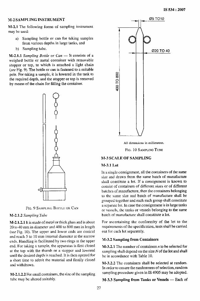
M-2 SAMPLING INSTRUMENT
M-2.1 The following forms of sampling instrumentmay be used:
a) Sampling bottle or can for taking samplesfrom various depths in large tanks, and
b) Sampling tube.
M-2.1.1 Sampling Bottle or Can — It consists of aweighed bottle or metal container with removable
stopper or top, to which is attached a light chain(see Fig. 9). The bottle or can is fastened to a suitablepole. For taking a sample, it is lowered in the tank tothe required depth, and the stopper or top is removedby means of the chain for filling the container.
FIG. 9 SAMPLINGBOTTLEORCAN
M-2.1.2 Sampling Tube
M-2.1.2.1 It is made of metal or thick glass and is about20 to 40 mm in diameter and 400 to 800 mm in length
(see Fig. 10). The upper and lower ends are conicaland reach 5 to 10 mm internal diameter at the narrow
ends. Handling is facilitated by two rings at the upperend. For taking a sample, the apparatus is first closedat the top with the thumb or a stopper and lowereduntil the desired depth is reached. It is then opened fora short time to admit the material and finally closedand withdrawn,
M-2.1.2.2 For small containers, the size of the sampling
tube may be altered suitably.
27
IS 534:2007
05 TOl O‘H—
c—
D020 TO 40-
All dimensions in millimetres.
FIG. 10 SAMPLINGTUBE
M-3 SCALE OF SAMPLING
M-3.1 Lot
In a single consignment, all the containers of the samesize and drawn from the same batch of manufactureshall constitute a lot. If a consignment is known toconsist of containers of different sizes or of different
batches of manufacture, then the containers belongingto the same size and batch of manufacture shall begrouped together and each such group shall constitute
a separate lot. In case the consignment is in large tanksor vessels, the tanks or vessels belonging to the same
batch of manufacture shall constitute a lot.
For ascertaining the conformity of the lot to therequirements of the specification, tests shall be carriedout for each lot separately.
M-3.2 Sampling from Containers
M-3.2.1 The number of containers n to be selected for
sampling shall depend on the size N of the lot and shallbe in accordance with Table 10.
M-3.2.2 The containers shall be selected at random.
In order to ensure the randomness of selection, random
sampling procedure given in IS 4905 maybe adopted.
M-3.3 Sampling from Tanks or Vessels — Each of
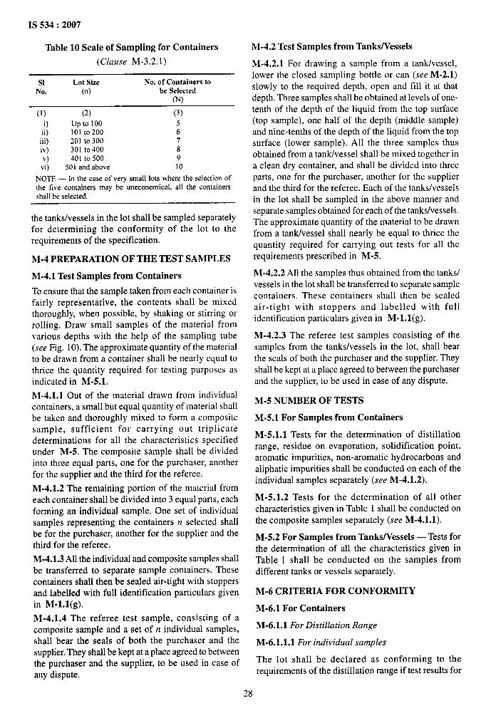
IS 534:2007
Table 10 Scale of Sampling for Containers
(Clause M-3.2. 1)
S1 Lot Size No. of Containers toNo. (n) be Selected
m)
(1) (2) (3)
i) up to 100 5ii) lot to200 6
iii) 201 to 300 7iv) 301to 400 8v) 401to 500 9
vi) 50 I and above 10
NOTE — In the case of veW small lots where the selection ofthe five containers may be uneconomical, all the containersshall be selected.
the tanks/vessels in the lot shall be sampled separatelyfor determining the conformity of the lot to therequirements of the specification.
M-4 PREPARATION OF THE TEST SAMPLES
M-4.1 Test Samples from Containers
To ensure that the sample taken from each container isfairly representative, the contents shall be mixedthoroughly, when possible, by shaking or stirring orrolling, Draw small samples of the material fromvarious depths with the help of the sampling tube
(see Fig. 10). The approximate quantity of the materialto be drawn from a container shall be nearly equal tothrice the quantity required for testing purposes asindicated in M-5.1.
M-4.1.1 Out of the material drawn from individualcontainers, a small but equal quantity of material shallbe taken and thoroughly mixed to form a compositesample, sufficient for carrying out triplicatedeterminations for all the characteristics specifiedunder M-5. The composite sample shall be dividedinto three equal parts, one for the purchaser, anotherfor the supplier and the third for the referee.
M-4.1.2 The remaining portion of the material fromeach container shall be divided into 3 equal parts, eachforming an individual sample. One set of individualsamples representing the containers n selected shallbe for the purchaser, another for the supplier and thethird for the referee.
M-4.1.3 All the individual and composite samples shallbe transferred to separate sample containers. These
containers shall then be sealed air-tight with stoppersand labelled with full identification particulars givenin M-1.l(g).
M-4.1.4 The referee test sample, consisting of acomposite sample and a set of n individual samples,shall bear the seals of both the purchaser and thesupplier. They shall be kept at a place agreed to betweenthe purchaser and the supplier, to be used in case ofany dispute.
M-4.2 Test Samples from Tanks/Vessels
M-4.2.1 For drawing a sample from a tarddvessel,lower the closed sampling bottle or can (see M-2.1)slowly to the required depth, open and fill it at thatdepth. Three samples shall be obtained at levels of one-tenth of the depth of the liquid from the top surface(top sample), one half of the depth (middle sample)and nine-tenths of the depth of the liquid from the topsurface (lower sample). All the three samples thusobtained from a tanldvessel shall be mixed together ina clean dry container, and shall be divided into threeparts, one for the purchaser, another for the supplierand the third for the referee. Each of the tanks/vesselsin the lot shall be sampled in the above manner andsepamte samples obtained for each of the tanks/vessels.The approximate quantity of the material to be drawnfrom a tanldvessel shall nearly be equal to thrice the
quantity required for carrying out tests for all therequirements prescribed in M-5.
M-4.2.2 All the samples thus obtained from the tanks/vessels in the lot shall be transferred to separate sample
containers. These containers shall then be sealedair-tight with stoppers and labelled with fullidentification particulars given in M-1.l(g).
M-4.2.3 The referee test samples consisting of the
samples from the tanks/vessels in the lot, shall bearthe seals of both the purchaser and the supplier. Theyshall be kept at a place agreed to between the purchaserand the supplier, to be used in case of any dispute.
M-5 NUMBER OF TESTS
M-5.1 For Samples from Containers
M-5.1.1 Tests for the determination of distillationrange, residue on evaporation, solidification point,aromatic impurities, non-aromatic hydrocarbons andaliphatic impurities shall be conducted on each of theindividual samples separately (see M-4.1.2).
M-5.1.2 Tests for the determination of all othercharacteristics given in Table 1 shall be conducted onthe composite samples separately (see M-4.1.1).
M-5.2 For Samples from Tanks/Vessels — Tests forthe determination of all the characteristics given inTable 1 shall be conducted on the samples from
different tanks or vessels separately.
M-6 CRITERIA FOR CONFORMITY
M-6.1 For Containers
M-6.1.1 For Distillation Range
M-6.1.1.1 For individual samples
The lot shall be declared as conforming to therequirements of the distillation range if test results for
28
each of the individual samples tested in respect ofdistillation range satisfy the requirements as given inTable 1, S1 No. (v).
M-6.1.1.2 For residue on evaporation, solidificationpoint, aromatic impurities and aliphatic impurities whichhave been tested on the individual samples, the mean(X) and the range (1?)of test results, shall be computed(the range is defined as the difference between themaximum and the minimum values of test results):
a) The lot shall be declared as conforming to therequirements of residue on evaporation,
aromatic impurities and aliphatic impuritiesif the value of the expression (X + 0.6 R) ascalculated from relevant test results are lessthan or equal to the respective values for eachof the requirement given in lldble 1.
IS 534:2007
b) The lot shall be declared as conforming to therequirements of solidification point if thevalue of the expression (X – 0.6 1?) ascalculated from relevant test results is equalto or more than the respective values given inTable 1.
M-6.1.1.3 For composite samples
In respect of all other characteristics, the lot shall beconsidered as conforming, if the composite samplesatisfies each one of these requirements.
M-6.2 For TanksNessels
The lot shall be declared as conforming to the specifiedrequirements for various characteristics, if each of thetest results satisfies the relevant requirements specifiedin the standard individually.
29
(Continuedfiom second cover)
ASTM D 1492:1996
ASTM D 1685:1995ASTM D 2359:1998ASTM D 4045:1996
ASTM D 4052:1996
ASTM D 4492:1996ASTM D 4629:1996
ASTM D4734 :19981S02211 :1973
Standard test method for bromine index of aromatic hydrocarbons by coulometrictitrationStandard test method for traces of thiophene in benzene by spectrophotometryStandard specification for refined benzene -535Standard test method for sulfir in petroleum products by hydrogenolysis andrateometric calorimetryStandard test method for density and relative density of liquids by digital densitymeterStandard test method for analysis of benzene by gas chromatographyStandard test method for trace nitrogen in liquid petroleum hydrocarbons bysyringe/inlet oxidative combustion and chemiluminescence detection
Standard specification for refined benzene-545Liquid chemical products — Measurement of colour in hazen units (Platinum-
Cobalt scale)
ASTM D 1353 is also available for determining the characteristic, Residue on Evaporation and in case of disputeclause 8 of IS 82, as given in Table 1 shall be the referee test method.
For the purpose of deciding whether a particular requirement of this standard is complied with, the final value,
observed or calculated, expressing the result of a test or analysis, shall be rounded off in accordance withIS 2:1960 ‘Rules for rounding off numerical values (revised)’. The number of significant places retained in therounded off value should be the same as that of the specified value in this standard.
Bureau of Indian Standards
BIS is a statutory institution established under the Bureau of Indian Standards Act, 1986 to promoteharmonious development of the activities of standardization, marking and quality certification of goodsand attending to connected matters in the country.
Copyright
BIS has the copyright of all its publications. No part of these publications may be reproduced in any formwithout the prior permission in writing of BIS. This does not preclude the free use, in the course ofimplementing the standard, of necessary details, such as symbols and sizes, type or grade designations.Enquiries relating to copyright be addressed to the Director (Publications), BIS.
Review of Indian Standards
Amendments are issued to standards as the need arises on the basis of comments. Standards are also reviewedperiodically; a standard along with amendments is reaffirmed when such review indicates that no changes areneeded; if the review indicates that changes are needed, it is taken up for revision. Users of Indian Standardsshould ascertain that they are in possession of the latest amendments or edition by referring to the latest issue of‘BIS Catalogue’ and ‘Standards : Monthly Additions’.
This Indian Standard has been developed from Doc : No. PCD 3 (23 11).
Amendments Issued Since Publication
Amend No. Date of Issue Text Affected
BUREAU OF INDIAN STANDARDS
Headquarters :
Manak Bhavan, 9 Bahadur Shah Zafar Marg, New Delhi 110002 Telegrams : Manaksanstha
Telephones :23230131, 23233375,23239402 (Common to all offices)
Regional Offices : Telephone
Central : Manak Bhavan, 9 Bahadur Shah Zafar Marg
{
23237617
NEW DELHI 110002 23233841
Eastern : 1/14 C.I,T. Scheme VII M, V, I. P. Road, Kankurgachi
{
23378499,23378561
KOLKATA 700054 23378626,23379120
Northern : SCO 335-336, Sector 34-A, CHANDIGARH 160022
{
26038432609285
Southern : C,I.T. Campus, IV Cross Road, CHENNAI 600113
{
22541216,2254144222542519,22542315
Western : Manakalaya, E9 MIDC, Marol, Andheri (East)
{
28329295,28327858
MUMBAI 400093 28327891,28327892
Branches : AHMEDABAD. BANGALORE, BHOPAL. BHUBANESHWAR. COIMBATORE. FARIDABAD.GHAZIABAD. GUWAHATI. HYDERABAD. JAIPUR. KANPUR. LUCKNOW. NAGPUR.PARWANOO. PATNA. PUNE. RAJKOT, THIRUVANANTHAPURAM. VISAKHAPATNAM.
Printed by Sunshine Graphics


![is.6964.2001 [IEC 61260 (1995)] [law.resource.org]](https://img.pdfslide.net/doc/110x75/577cc9b81a28aba711a46e5e/is69642001-iec-61260-1995-lawresourceorg.jpg)


![is.15575.2.2005 [IEC 61672-2 (2003)] [law.resource.org]](https://img.pdfslide.net/doc/110x75/577cc9b81a28aba711a46e60/is1557522005-iec-61672-2-2003-lawresourceorg.jpg)

