Embed Size (px)
Citation preview

Disclosure to Promote the Right To Information
Whereas the Parliament of India has set out to provide a practical regime of right to information for citizens to secure access to information under the control of public authorities, in order to promote transparency and accountability in the working of every public authority, and whereas the attached publication of the Bureau of Indian Standards is of particular interest to the public, particularly disadvantaged communities and those engaged in the pursuit of education and knowledge, the attached public safety standard is made available to promote the timely dissemination of this information in an accurate manner to the public.
इंटरनेट मानक
“!ान $ एक न' भारत का +नम-ण”Satyanarayan Gangaram Pitroda
“Invent a New India Using Knowledge”
“प0रा1 को छोड न' 5 तरफ”Jawaharlal Nehru
“Step Out From the Old to the New”
“जान1 का अ+धकार, जी1 का अ+धकार”Mazdoor Kisan Shakti Sangathan
“The Right to Information, The Right to Live”
“!ान एक ऐसा खजाना > जो कभी च0राया नहB जा सकता है”Bhartṛhari—Nītiśatakam
“Knowledge is such a treasure which cannot be stolen”
“Invent a New India Using Knowledge”
है”ह”ह
IS 8442 (2008): Stand post type water and foam monitor forfire fighting -Specification [CED 22: Fire Fighting]


IS 8442:2008
Indian Standard
STAND POST TYPE WATER AND FOAM MONITORFOR FIRE FIGHTING — SPECIFICATION
( First Revision)
ICS 13.220.10
0 BIS 2008
BUREAU OF INDIAN STANDARDSMANAK BHAVAN, 9 BAHADUR SHAH ZAFAR MARG
NEW DELHI i 10002
May 2008 Price Group 4

Fire Fighting Sectional Committee, CED 22
FOREWORD
i, This Indian Standard (First Revkion) was adopted by the Bureau of Indian Standards, after the draft finalized bythe Fire Fighting Sectional Committee had been approved by the Civil Engineering Division Council.
Water monitors are fixed on the fire fighting appliances and are one of the important equipment used for fightingfire. Whh the help of this equipment it is possible to direct the flow of water at any angle on horizontal andvertical axis. This standard has been formulated to lay down minimum performance requirements.
When the water monitor is used with sea water, aluminium parts should not be used.
This standard was first published in 1977. The present revision includes modifications with regard to inclusion ofcopper alloy and stainless steel components and figures have been modified according to various types of monitors.The materials of construction are given in Table 2 with an idea to use compatible material for all components inindividual monitor.
For the purpose of deciding whether a particular requirement of this standard is complied with, the final value,observed or calculated, expressing the result of a test or analysis, shall be roundedoff in accordancewithIS 2:1960 ‘Rules for rounding off numerical values (revised)’. The number of significant places retained in therounded off vafue should be the same as that of the specified value in this standard.

IS 8442:2008
Indian Standard
STAND POST TYPE WATER AND FOAM MONITORFOR FIRE FIGHTING — SPECIFICATION
(First Revision)
1 SCOPE
This standard lays down the requirements for standpost type monitor of size 63 mm, 75 mm and 100 mmused for fire fighting. This standard covers followingtypes of monitors:
a) Water monitor, and
b) Foam-cum-water monitor:
1) With water/foam barrel with aspiratingtype nozzle, and
2) With non-aspirating type jet(spraynozzle.
2 REFERENCES
The standards listed in Annex A contain provisions,which through reference in this text constituteprovisions of this standard. At the time of publication,the editions indicated were valid. All standards aresubject to revision and parties to agreements based onthis standard are encouraged to investigate thepossibility of applying the most recent editions of thestandards indicated at Annex A.
3 GENERAL
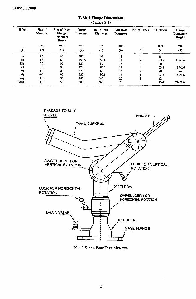
3.1 The size of water monitor is denoted by itswaterway dimension which shall be as per Table 1 orprovided by the purchaser as per their requirement.
3.2 Monitors are designed for rated discharge capacityof 1750 l/rein for 63 mm size, 2580 l/rein for 75 mmsize, and 3500 l/rein for 100 mm size at inlet pressureof 0.7 N/mm*, at nozzle end.
3.3 The shape of the monitor shall be so designed thatit shall allow free flow of water with minimum frictionloss and maximum stability against nozzle reaction.The shapes are generally as shown in Fig. 1 and Fig. 2.
3.4 The monitor shall consist of following components:
a) Base flange,
b) Reducer — wherever applicable,
c) Water barrel of seamless pipe,
d) Elbow 90° and 45°,
e) Swivel joint for horizontal and verticalrotation,
f) Lock handles for horizontal and verticalrotation,
g) Nozzle (details as given in 5.2),
h) Handle or worm and worm wheel to facilitatevertical rotation, and
j) Drain valve.
4 MATERIAL
Material for different components shall be as perTable 2.
NOTES
1 Ahsminium components shalI not be used with sea water.
2 The material of construction to be seJected as agreed tobetween the purchaser and the manufacturer k~pkg in V!EW
the compatibility of materials.
5 CONSTRUCTION
5.1 Monitor shall have the flange of diametercorresponding to standpost, that is, 63 mm, 75 mmand 100 mm respectively. Flanges of higher size maybe used for better hydraulic efficiency and in that caseit shall be welded with reducer. The swivel joint whichshall be connected with pipe by screwing or weldingso as to have horizontal rotation of 360° in eitherdirection and vertical rotation of minimum 135° (90°upward and 45° downward). Traversing mechanismshall be provided to facilitate the horizontal and verticalrotation of monitor. This shall be either single handlebar type or worm and worm wheel type. Positive locksshall be provided for unattended operation. In case ofworm and worm wheel geared unit, it shall be self-locklng type. Drain valve shall be fitted above inletflange to drain water from water barrel after usage.
5.2 The construction of monitor shall be welded,screwed or flanged. All screwed joints except nozzleshall have minimum threading length of 20 mm andepoxy based sealant shall be used and threads shall belocked permanently so that threads will not getunscrewed during horizontal or vertical rotation ofmonitor. The outlet of barrel shall have external threadsconfirming to IS 2643 with class A tolerance. Thenozzle shall be of standard orifice size as given inFig. 3, 4 and 5 and confirming to performancerequirements given in 9. The inlet of the nozzle shallbe provided with external hexagon or other means tofacilitate tightening of nozzle and internal threads tosuit the monitor outlet barrel size.
IS 8442:2008
Table 1 Flange Dimensions(Clause 3.1)
S1 No. Size of Size of Inlet Outer Bolt Circle Bolt Hole No. of Holes Thickness FlangeMonitor Flange Diameter Dmmeter Diameter Diameter/
(Nominal HeightBore)
mm mm mm mm mm mm mm
(1) (2) (3) (4) (5) (6) (7) (8) (9)
i)ii)
iii)iv)
v)vi)
vii)viii)
63637575
100100100100
8080
I00100I(XI100150150
200190.5220220220220285280
160152.4180190.5180190.5240240
1919191919192222
44448888
1823.82023.82023.82225.4
—127/1.6
—157/1.6
—157/1 .6
—216/1.6
THREADS TO SUIT
NOzzLE HANDLE
. .
SWIVEL JOINT FOR ‘VERTICAL ROTATION LOCK FOR VERTICAL
iLOCK FOR HORIZONTAL 90° ELBOW1ROTATION
I
J SWIVEL JOINT FORHORIZONTAL ROTATION
DRAIN VALVEI
REDUCER
BASE FLANGE
,rl~l , III
FIG. 1 STANDPOSTTYPE MONITOR

‘1
IS 8442:2008
Table 2 Material(Foreword, and Clause 4)
S1 Component MaterialNo.
/Mild Steel Copper Alloy Construction Stainless Steel
\
Construction Construction
(1) (2) (3) (4) (5)
i) Base flange
ii) Reducer
iii) Elbow
iv) Swivel jointiworm andworm wheel
v) Lock handle
vi) Water barrel
vii) Nozzle/Jet
spray nozzle
viii) Handle
ix) Worm shatl
x) Foam barrel
xi) Hand wheel
xii) Drain valve
Carbon steel conforming toIS 6392 or Mild steel conformingto IS 2062Pipe fittings conforming to [S11428 (Parts1 to 3)Pipe fittings conforming to IS11428 (Parts 1 to 3)Grade 2/3 of IS 318 or Grade 3 ofIs 304
Brass conforming to IS 291 orIS 319 or stainless steel
conformingtoIS6603Mild steel conforming to IS 11428(Parts 1 to 3) or brass tubeconforming to IS 407 oraluminium conforming to1S 1285 and IS 2673Copper allo] conformin~ t? ~~~$
2/3 ofIS 318 or Grade 3 of IS 304 oraluminium alloy conforming toGrade 4450 or 4225 of IS 617Mild steel conforming to IS 1732
Stainless steel conforming toIS 6603Brass tube conforming to IS 407 orahrminium conforming to 1S 1285and IS 2673Cast iron conforming to Grade 200of Is 210Copper alloy conforming to IS 778
Grade 2/3 ofIS318 orGrade 3 of IS 304
Grade 2/3 ofIS318 orGrade 3 of 1S 304Grade 2/3 ofIS318 orGrade 3 of IS 304Grade 2/3 of IS 318 orGrade 3 of IS 304
Brass conforming to IS 291 orIS 319 or S.S. conforming to
IS 6603Brass tube conforming to IS 407
QPpgI alloyconformingtoGrade2/3 ofIS318 or Grade 3 of IS 304
Mild steel conforming to1S 1732Stainless steel conforming toIS 6603Brass tube conforming to IS 407 orahrminium conforming to IS 1285and IS 2673Cast iron conforming to Grade 200Ofls 210Copper alloy conforming to IS 778
Plates, sheets conforming to IS 6911
Stainless steel
Stainless steel
Grade 2/3 of1S318 orGrade 3 of IS 304 or Stainlesssteel conforming to IS 6603Stainless steel conforming to1S 6603
Stainless steel
Mainltwsleelcmtfhmifig?BIs 3444
Mild st:el conforming to IS 1732
Stainless steel conforming toIS 6603Stainless steel
Cast iron conforming to Grade 200of Is 210Stainless steel
6 WORKMANSHIP AND FINISH
The complete assembly shall be of good workmanshipand finish and free from burrs and sharp edges.Particularly, waterway shall have smooth finish.
7ANTI-CORROSIVE TREATMENT
All steel components subject to direct water contact shallbe hot dip galvanized after fabrication to a minimumthickness of 0.03 mm. The aluminium parts subject todirect water contact shaIl be hard anodized to a minimumthicknessof 0.015 mm. The thickness of galvanizing shallbe measured with suitable thickness measuring meter.
8 PAINTING
Monitor shall be painted with fire red or post officered colour conforming to shade No. 536 or 538 ofIS 5. The paint shall conform to IS 2932.
9 PERFORMANCE REQUIREMENTS
9.1 Water Monitor
The monitor shall be tested at operative pressure
of 0.7 N/mmz at nozzle end, at an angle of 30° fromhorizontal in still air condition. It shall have minimumdischarge capacity and horizontal throw as given inTable 3.
Table 3 Minimum Discharge Capacity andHorizontal Throw of Water Monitor
S1No. Size Discharge Capacity Horizontal ThrowMin &fin
mm I/rein m
(1) (2) (3) (4)
i) 63 1750 53ii) 75 2580 60
iii) 100 3500 64
9.2 Foam-cum-Water Monitor
The monitor shall be tested at operative pressureof 0.7 N/mm* at nozzle end, at an angle of 30° fromhorizontal in still air condition. It shall haveminimum discharge capacity and horizontal throwas Table 4.
3

IS 8442:2008
FIG. 2 STANDPOSTTYPE MONITOR-WORMANDWORM WHEELTYPE
I \ SMALLER ORIFICE TIPS I
NOTES
1 The Orifice Diameter for 63 mm, 75 mm, and 100 mm Size Shall be Respectively 32 mm, 38 mm, and 45 mm, Min.2 The Length (L) of Nozzle Shall be Such as to Give Desired Performance Requirement.
FIG. 3 JETSPRAYNOZZLE
4

kdl&
IS 8442:2008
1, & LFOAM INDUCTION
JBODY
--------,r. -----
(
!YA’pROx”)
k‘\,
‘\ STRAINER‘\ (600mm LONG APPROX.)
‘\,\‘\,
\\
\‘\%
\
FIG. 4 AIR ASPIRATIONTYPE FOAM lNDUCEDNOZZLE
ROL
“CKV(3000mm LONG APPROX.)
k STRAINERAPPROX.)
FIG. 5 NON-AIR ASPIRATINGTYPE JET/SPRAYNOZZLE
5
II
m,:,IS 8442:2008
Table 4 Minimum Discharge Capacity andHorizontal Throw Foam-cum-Water Monitor
(Clause 9.2)
sl Size Discharge Horizontal HorizontalNo. Capacity Throw Throw
(Water) (Foam)Min Min Min
mm llmin m m
(1) (2) (3) (4) (6)
i) 63 1750 53 45ii) 75 2580 60 50iii) 100 3500 64 55
NOTE — This shall be a type test,
10 LEAKAGE TEST
10.1 The entire assembly shall be hydraulically testedto a pressureof 2.3 N/mmzfor 5 minandthereshallnot be any leakage.
10.2 Ttte entire assembly shall be hydraulically testedto a pressure of 2.3 IWmmz and horizontal rotation shall
be carried Dul 5 timesandthenverticalrotationupanddown for 5 cycles. During the test there shall be noleakage observed in any of the swiveled joints. Afterthe above test is carried out, the performance test as
given in 9.1 shatl be performed and assembly shatl meetthe requirements.
11 ACCESSORIES
The accessories shall include nozzle spanner whichshall be optional.
12 MARKING
12.1 Each monitor shall be clearly and permanentlymarked with the following:
a) Manufacturer’s name and his trade-mark,
b) Year of manufacture, and
c) Discharge capacity, in l/rein.
12.2 BIS Certification Marking
The monitor may also be marked with the StandardMark.
12.2.1 The use of the Standard Mark is governed bythe provisions of the Bureau of [rzdiarz Standards Act,1986 and the Rules and Regulations made thereunder.
The details~fconditionsunderwhi~hthe licenmforthe use of Standard Mark may be granted tomanufacturers or producers may be obtained from theBureau of Indian Standards.
ANNEX A
(Clause 2)
LIST OF REFERRED INDIAN STANDARDS
IS No. Title
5 :2004 Colours for ready mixed paints andenamels (@h revision)
210:1993 Grey iron casting — Specificationfourth revision)
291:1989 Machining purposes — Specification(third revision)
304:1981 Specification for high tensile brassingots and castings (second revision)
318:1981 Specification for leaded tin bronzeingots and castings (second revision)
319:1989 Free cutting leaded brass bars, rodsand sections — Specification (fburthrevision)
IS No. i“ltle
407:1981 Specification for brass tubes forgeneral purposes (third revision)
617:1994 Aluminium and aluminium alloyingots and castings for generalengineering purposes (third revision)
778:1994 Specification for copper atloy gate,globe and check valves for waterworks purposes ~ourth revision)
1285:2002 Wrought aluminium and atuminiumalloys — Extruded round tube andhollow sections for generalengineering purposes —Specification (third revision)

IS 8442:2008
IS No. Title
1732:1989 Dimensions for round and squaresteel bars for structural and generalengineering purposes (secondrevision)
2062:2006 Hot rolled low, medium and hightensile structural steel (sixth revision)
2643:1999 Pipe threads where pressure tightjoints are not made on the threads —Dimensions, tolerances anddesignation
2673:2002 Dimensions for wrought aluminiumand aluminium alloys extruded roundtube — Specification (secondrevision)
IS No.
2932:2003
3444:1999
6392:19716603:2001
6911:1992
11428 (parts 1to 3) :1985
Title
Enamel, synthetic, exterior: (a)undercoating, (b) finishing —Specification (third revision)Corrosion resistant high alloy steeland nickel base castings for generalapplications — Specification (thirdrevision)Steel pipe flangesStainless steel bars and flats —Specification ~rst revision)Stainless steel plate, sheet and strip@rst revision)Specification for wrought carbon steelbutt welding pipe fittings
I
7

Bureau of Indian Standards
EIIS is a statutory institution established under the Bureau of Indian Standards Act, 1986 to promoteharmonious development of the activities of standardization, marking and quality certification of goodsand attending to connected matters in the country.
Copyright
BIS has the copyright of all its publications. No part of these publications may be reproduced in any formwithout the prior permission in writing of BIS. This does not preclude the free use, in the course ofimplementing the standard, of necessary details, such as symbols and sizes, type or grade designations.Enquiries relating to copyright be addressed to the Director (Publications), BIS.
Review of Indian Standards
Amendments are issued to standards as the need arises on the basis of comments. Standards are also reviewedperiodically; a standard along with amendments is reaffirmed when such review indicates that no changes areneeded; if the review indicates that changes are needed, it is taken up for revision. Users of Indian Standardsshould ascertain that they are in possession of the latest amendments or edition by referring to the latest issue of‘BIS Catalogue’ and ‘Standards : Monthly Additions’.
Thjs JndLm Standard has been developed from I)OC :No, CED 22 (7344).
Amendments Issued Since Publication
Amend No. Date of Issue Text Affected—
BUREAU OF INDIAN STANDARDS
Headquarters:
Manak Bhavan, 9 Bahadur Shah Zafar Marg, New Delhi 110002 Telegrams: ManaksansthaTelephones :23230131,23233375,2323 9402 (Common to all offices)
Regional Oflices: Telephone
Central :
Eastern :
Northern :
Southern :
Western :
Branches :
Manak Bhavan, 9 Bahadur Sjah Zafar Marg
{
23237617NEW DELHI 110002 23233841
1/14 C.1.T. Scheme VII M, V. I. P. Road, Kankurgachi
{
23378499,23378561KOLKATA 700054 23378626,23379120
SCO 335-336, Sector 34-A, CHANDIGARH 160022
{
603843609285
C.I.T. Campus, IV Cross Road, CHENNAI 600113
{
22541216,2254144222542519,22542315
Manakalaya, E9 MIDC, Marol, Andheri (East)
{
28329295,28327858MUMBAI 400093 28327891,28327892
AHMEDABAD. BANGALORE. BHOPAL. BHUBANESHWAR. COIMBATORE. FARIDABAD.GHAZIABAD. GUWAHATI. !iYDERABAD. JAIPUR. KANPUR, LUCKNOW. NAGPUR.PARWANOO. PATNA. PUNE. RAJKOT. THIRUVANANTHAPURAM. VISAKHAPATNAM.
Printed at: Prabhat Offset Press, New Delhi-2


![The DFLU flux for systems of conservation laws · arXiv:1401.0190v1 [cs.NA] 31 Dec 2013 RESEARCH ISSN 0249-6399 ISRN INRIA/RR--8442--FR+ENG REPORT N° 8442 December 2013 Project-Team](https://img.pdfslide.net/doc/110x75/5ecf73156dae822b9756e881/the-dflu-iux-for-systems-of-conservation-laws-arxiv14010190v1-csna-31-dec.jpg)