Embed Size (px)
Citation preview
Acta of Bioengineering and BiomechanicsVol. 8, No. 1, 2006
Is a “movable hinge axis” used bythe human stomatognathic system?
K. M. THIEME, D. KUBEIN-MEESENBURG, D. IHLOW, H. NÄGERL
Department of Orthodontics, Georg-August-University of Göttingen,Robert-Koch-Str. 40, D-37099 Göttingen, Germany.
Tel.: +49-551 – 39-9697, +49-551 – 39-8344. Fax: +49-551 – 39-8350.E-mail: [email protected]; [email protected];
[email protected]; [email protected]
This treatise deals with sagittal in vivo motions of the human mandible. The concept of a “movablehinge axis”, which is commonly used in dentistry, was scrutinised theoretically and empirically. Wewondered whether a “movable hinge axis”– or better a mandibularly fixed hinge axis (MFHA) – wasactually used by subjects with sound temporomandibular joints. To answer this question we first showedthat the assumptions of a MFHA would comprise that of the neuromuscular apparatus of thestomatognathic system piloting the mandible by solely two kinematical degrees of freedom (DOF). Wespatially recorded in vivo motions of mandibles with high-precision ultrasonic devices. The subjects wereasked to guide their mandibles in sagittal movements so that the lower incisal edges ran along the Posseltdiagrams. The mathematical procedure is described in detail, hence a possible use of two DOF by asubject could quickly be puzzled out from a set of motions. These analyses revealed that the quasi-planemandibular movements were approximately piloted by two kinematical DOF in subjects with soundtemporomandibular joints. The grade of approximation was measured. Thus, the ensemble of possiblepositions of the moved body (mandible) can be described by a coordinate system, which is inherent in thestomatognathic system. Lacking precision and poor reproducibility in using only two variables formandibular position control yield hints that the subject has clinical problems in his stomatognathicsystem.
Key words: human mandible, mandibular movements, movable hinge axis, degrees of freedom, inherentcoordinate system, neuromuscular system
1. Introduction
Up to now axiography is a major part of instrumental analyses in clinical dentalpractices to evaluate functional states of the stomatognathic system. It is said to
K. M. THIEME et al.
record the path of the so-called “movable hinge axis” of the mandible. The procedureis as follows: The dental surgeons mostly guide the patient’s mandible out of centricocclusion (CO) in a small movement parallel to the sagittal plane and thus producea finite rotational axis in the region of the temporomandibular joint (TMJ). If itslateral projection looks like a point this axis is said to be the “movable hinge axis“which would remain stationary in the mandible and abount which the mandible wouldrotate [1]–[4]. This statement was often criticized [5]–[9]. NÄGERL et al. [10] haveproved that this axiographically defined “movable hinge axis” physically makes nosense since it has no prominent kinematical significance compared with other linesconnecting two mandibular points. To find definitely a mandibularly fixed axis, ifsuch exists, the following approach has to be adopted:Firstly the subjects should be able to perform quasi-plane sagittal mandibularmovements keeping the three degrees of freedom (DOF) negligibly small belonging tolateral shift, horizontal and frontal rotation. The ensemble of possible positions of themoved body (mandible) in the reference system (maxilla) is then given by the positionof an arbitrarily taken mandibular point (2 DOF), which lies within a plane domainwhose margin consists of a closed curve and the mandibular rotation (1 DOF). But, ifa distinct mandibular point exists, whose domain is degenerated to a pure linesegment, the criterion for the existence of the “movable hinge axis” – or bettermandibularly fixed hinge axis (MFHA) – would be fulfilled. Only then the subjectwould reduce the control of mandibular positions to 2 DOF: The position of the point
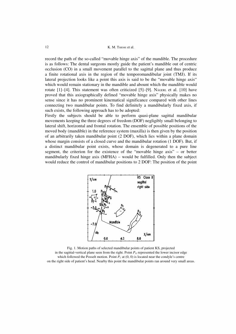
Fig. 1. Motion paths of selected mandibular points of patient KS, projectedin the sagittal-vertical plane seen from the right. Point PLI represented the lower incisor edge
which followed the Posselt motion. Point PC at (0, 0) is located near the condyle’s centreon the right side of patient’s head. Nearby this point the mandibular points ran around very small areas.
12
Is a “movable hinge axis” used by the human stomatognathic system?
Point Pmin moved on the same path there and back while opening and closing the mouth.Remark the change of the sense of circulation for points above and below Pmin
on this line segment (arc length) and the rotation angle. For any cyclic movement ofthe mandible this special point must move on this line segment back and forth.
We would like to demonstrate by in vivo measurements whether or not thereduction from 3 to 2 DOF of the mandible’s position may actually be possible. An11-year old girl was asked to pilot her mandible as much as possible along the bordersof the domain of the mandibular positions parallel to the sagittal plane: The startingposition was CO. She moved her mandible to the most anterior possible positionunder teeth contact, opened her mouth as far as possible, and closed her mouth in aposterior motion to reach CO again. She complied with our requests and piloted hermandible along far distant positions in a plane fashion as we could check by thespatial kinematical measurements. The paths of some mandibular points werecalculated from the recorded data (figure 1). The edge of the lower incisor PLI ranaround the area of the well-known Posselt diagram [11]. The path of the point PC
(located near the condyle’s centre) enclosed a domain just as the paths of the pointsP3, P4, P5, P6. For the point Pmin, however, the domain seemed to be degenerated to aline segment on which this point ran there and back. At first sight Pmin fulfilled thecriterion of a maxillarily movable and mandibularly fixed hinge axis as describedabove. The girl was apparently able to pilot diverse plane movements betweenmandibular positions having long distances from each other by using only 2 DOF: Aposition i of the mandible can be described by the pair (Li, α i). Li is the arc lengthcovered by the hinge axis Pmin along its path starting from CO (L0 = 0, α0 = 0°), and αi is the angle of mouth opening in relation to CO (figure 2).
13
K. M. THIEME et al.
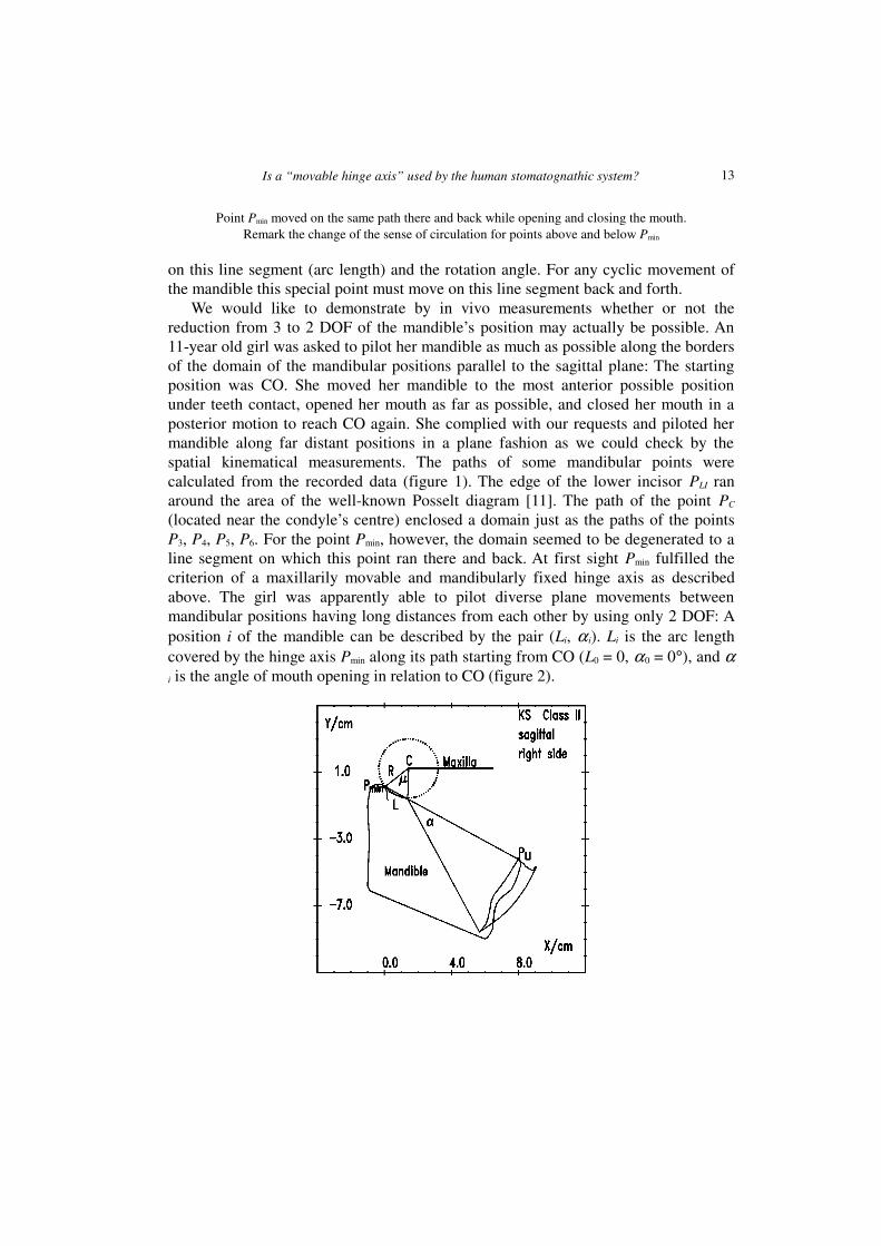
Fig. 2. The motion path of point Pmin could closely be approximated by a circlewith the centre C and radius R. L is the arc length covered by Pmin, α is the angle
of mouth opening in relation to centric occlusion
In the following we describe the mathematical procedure by which the possiblereduction from 3 to 2 DOF of the mandibular movements can be figured out fromspatial in vivo measurements and by which the grade of approximation of usinga MFHA by the neuromuscular system can be estimated.
2. Material and mathematical method
2.1. Experimental apparatus
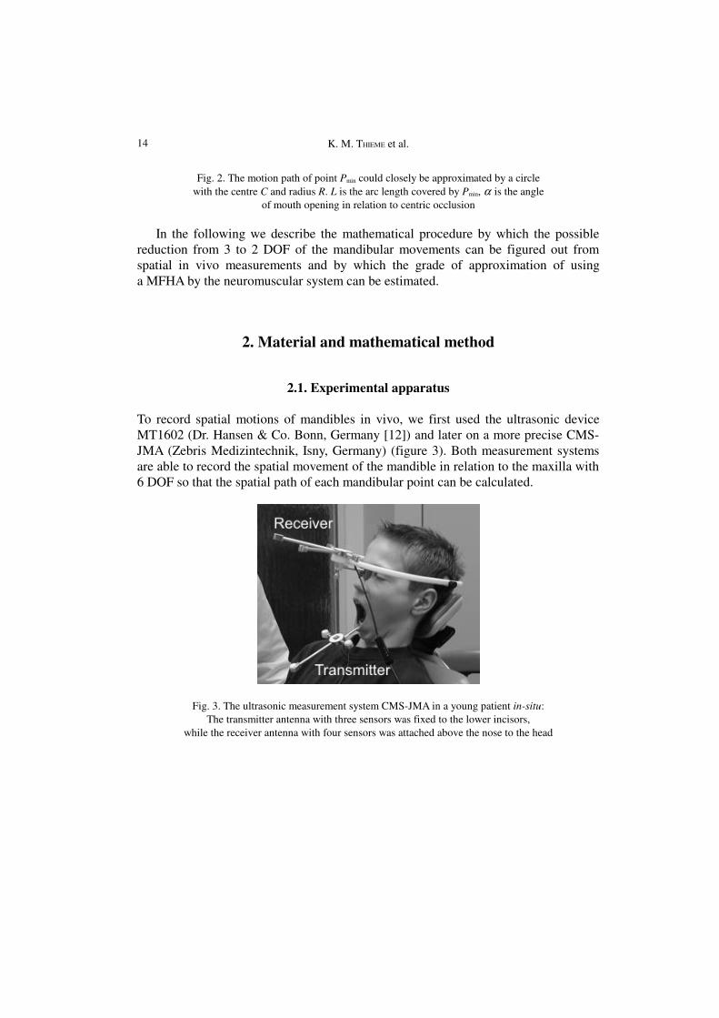
To record spatial motions of mandibles in vivo, we first used the ultrasonic deviceMT1602 (Dr. Hansen & Co. Bonn, Germany [12]) and later on a more precise CMS-JMA (Zebris Medizintechnik, Isny, Germany) (figure 3). Both measurement systemsare able to record the spatial movement of the mandible in relation to the maxilla with6 DOF so that the spatial path of each mandibular point can be calculated.
Fig. 3. The ultrasonic measurement system CMS-JMA in a young patient in-situ:The transmitter antenna with three sensors was fixed to the lower incisors,
while the receiver antenna with four sensors was attached above the nose to the head
14
Is a “movable hinge axis” used by the human stomatognathic system?
2.2. The subjects
Up to now we have measured more than 120 subjects with the MT1602 and morethan 30 subjects with the CMS-JMA as described by way of introduction. To figureout the number of DOF used for mandible control we scrutinised in detail quasi-planemandibular movements of 17 adult persons without orthodontic treatment classifiedas class I and 20 young and adult class-I-patients after orthodontic treatment recordedby the MT1602 as well as 28 young class-II-patients before orthodontic treatmentmeasured by the CMS-JMA.
2.3. Search for the mandibularly fixed hinge axis (MFHA)
We took into account the shapes and values of the areas around which mandibularpoints drove (figure 1): The lower incisal edge PLI drove clockwise along its Posseltdiagram just like other mandibular points nearby (P1) yielding mathematicallynegative areas A2. The points in the posterior region (P2), however, droveanticlockwise yielding A2 > 0. The points PC, P3, P4, P5, P6 ran along loops. Thereforethe areas were composed of positive ( j) and negative (k) parts: �� += kj AAA 222 .The loops of the points P3 and P4, above and below PC, showed opposite sense ofcirculation.
These observations made on all subjects suggested the following qualitativestatements:
1. With regard to the sense of circulation a line l0 must exist which separates thepositive from the negative areas A2. This line l0 is the geometric locus of themandibular points which run along loops whose positive and negative partial areasadd up to zero: �� += kj AAA 222 = 0 with A2j > 0 and A2k < 0. These observations
correspond to the theorem of Steiner (1840) of plane kinematics: The geometric locusof the points of the moved plane (mandible), whose closed paths surround areas A2 ofthe same size, forms a circle. The circles of different sizes of A2 have the commoncentre S, the so-called Steiner point [13].
2. Considering the absolute areas �� += || 221 kj AAA we arrive at the
conclusion that among the points of the line l0 there must exist a point Pmin(l0), whosepath encloses a minimal absolute area A1min, since in comparison with the cranial pointsof the line l0 its caudal points ran along their loops with A2 = 0 in opposite sense ofcirculation.
3. If the absolute area A1min of the point Pmin was found to be zero (A1min = 0) thesubject has only used 2 DOF for piloting the mandible and actually adjusted a MFHA.
15
K. M. THIEME et al.
The calculation of the area A2 needs less computer programming and run time thanthe calculation of the absolute area A1 since for this calculation the crossing points ofthe loops have to be determined additionally. To find the point Pmin(A1min) thefollowing three steps kept the computational time short.
Step 1: A point within the domain of the condyle (PC) served as the centre fora square of 10�10 cm2 in the sagittal-vertical plane (x, y). This square was subdividedby a square net with a step width of 0.5 cm. By means of the measured data the pathof every net point P(x, y) was calculated. According to the clock frequency ofmeasurement the path shaped up as a series of n points defining a polygon with nvertices CP(xi, yi). The mathematical area of this polygon was split up in triangleswhich added up to the area A2:
��
���
�⋅−⋅+⋅−⋅⋅= −−++
−=
=� 100111
2
02 )(
21
nniiii
ni
i
yxyxyxyxA .
The calculated function A2(x, y) of the net points P(x, y) was then approximated bymeans of the method of least squares to the plane A2Plane(x, y). A2Plane(x, y) = 0 yieldedthe straight line sl0. We settled upon this procedure because a straight line sl0 wascommonly found to be a good approximation of the circular segment line l0 betweennegative and positive areas A2.
Step 2: On the straight line sl0 we searched for the point Pmin(sl0) whose pathenclosed the minimal absolute area A1. For this purpose we fitted a parabola to thefunction A1(P(sl0)) using Brent’s method [14]. According to the golden section searchthe procedure jumped back and forth and found very fast the minimum value ofA1(P(sl0)). This special procedure was considered to be very favourable because thesearched point Pmin was commonly found to be closely positioned to point Pmin(sl0)(see below).
Step 3: In order to find finally the point Pmin, we searched in the neighbourhood ofthe point Pmin(sl0) using Powell’s method [14] in two preferred directions: Vertical tothe straight line sl0 and parallel to it. This procedure was a combination of multi-dimensional and one-dimensional minimization. Mostly it was sufficient to calculatethe minimal value of the area A1 once vertical to the straight line sl0 and once againparallel. Rarely a second iteration was necessary.
16
Is a “movable hinge axis” used by the human stomatognathic system?
3. Results
3.1. The straight line sl0
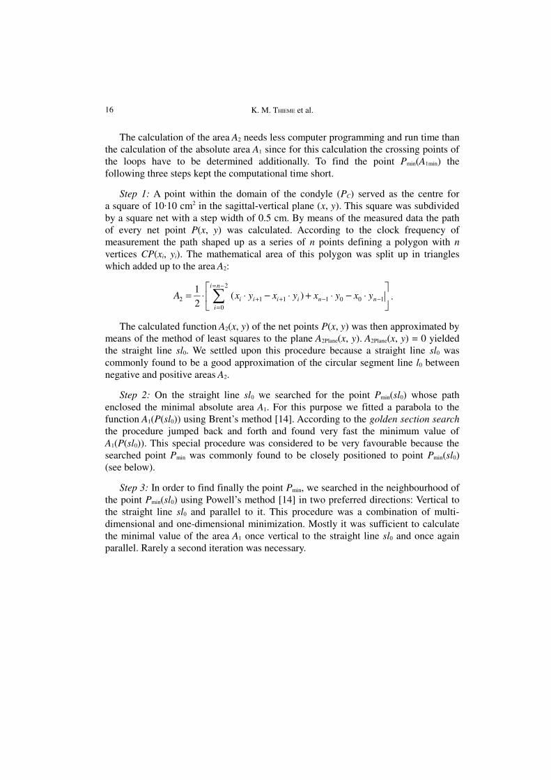
In step 1 of our procedure, the function A2(x, y) was favourably fitted by the planeA2Plane(x, y) since A2(x, y) mostly represented nearly a plane. Figure 4 demonstrates thisfact by the girl’s data (figure 1). The functions A2(x, y = +5 cm, 0, and –5 cm) nearlyformed straight lines. Consequently the contour lines of A2(x, y) = constant nearlyformed straight lines, too, which were parallel to the straight line sl0(A2 = 0) (figure5).
Fig. 4. Data of patient KS: Areas A2 calculated from the paths of the net points P(x, y = const.)with y ∈ (+5 cm, 0, –5 cm). The graphs A2(x, y = const.) almost formed straight lines
17
K. M. THIEME et al.
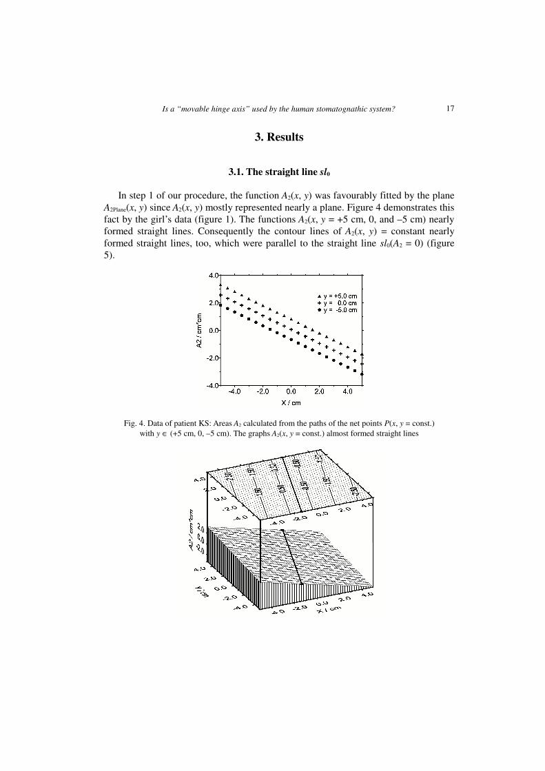
Fig. 5. Data of patient KS: A square of 10�10 cm2 was laid around the point PC.For net points of this square (distance = 0.1 cm) the paths and the corresponding areas A2 were calculated.
In excellent approximation, the contour line graph (upper part) yielded straight linesincluding straight line sl0 (for area A2 = 0). A2(x, y) practically represented a plane (lower part)
For most of the 37 young and adult class-I-patients and the 28 young class-II-patients the contour lines for A2 in the region of 10�10 cm2 were straight lines in thedemonstrated good approximation. Hence, the approximation of the parting line l0 forthe positive and negative areas A2 by the straight line sl0 was found to be the usefulstep 1 in our mathematical procedure.
3.2. The area A1min of the point Pmin
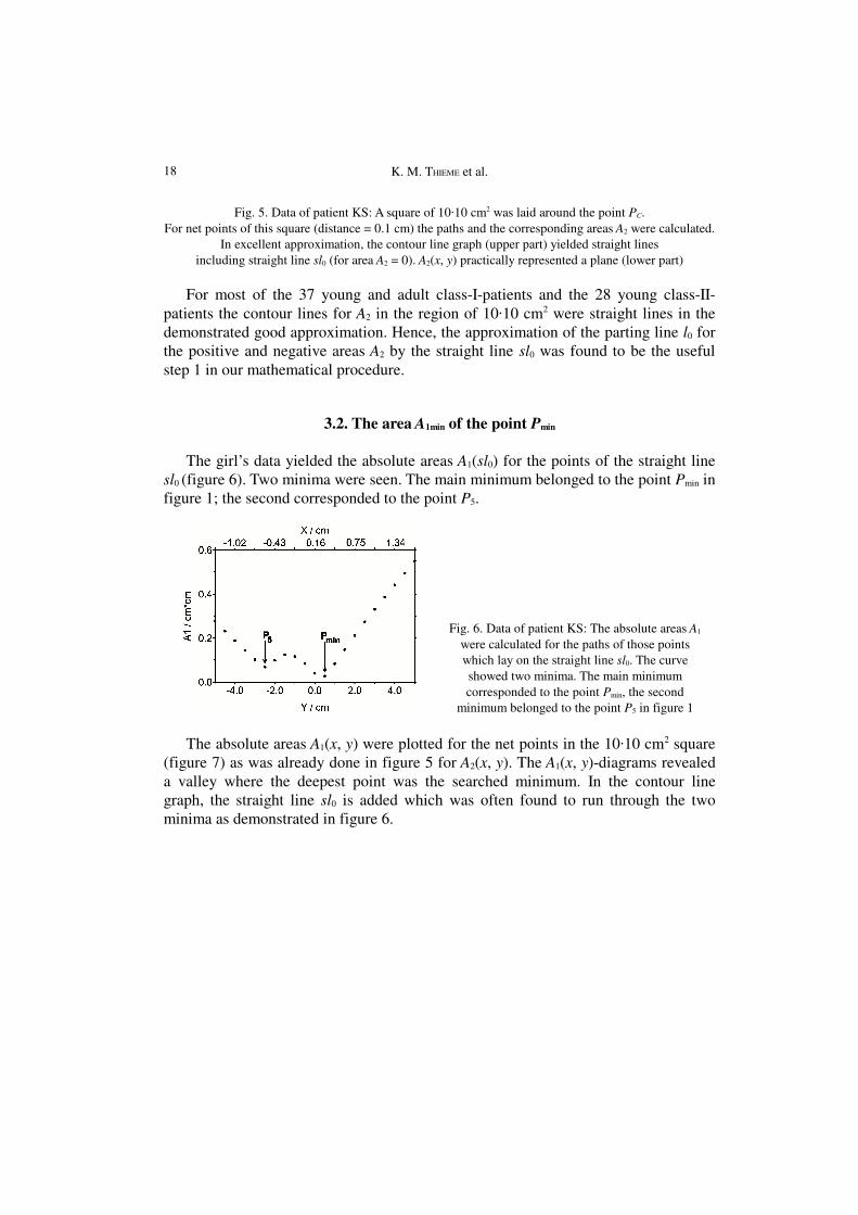
The girl’s data yielded the absolute areas A1(sl0) for the points of the straight linesl0 (figure 6). Two minima were seen. The main minimum belonged to the point Pmin infigure 1; the second corresponded to the point P5.
Fig. 6. Data of patient KS: The absolute areas A1
were calculated for the paths of those pointswhich lay on the straight line sl0. The curveshowed two minima. The main minimumcorresponded to the point Pmin, the second
minimum belonged to the point P5 in figure 1
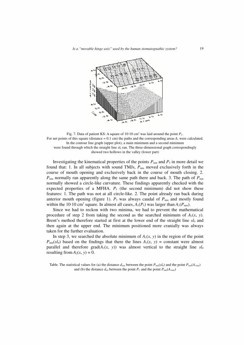
The absolute areas A1(x, y) were plotted for the net points in the 10�10 cm2 square(figure 7) as was already done in figure 5 for A2(x, y). The A1(x, y)-diagrams revealeda valley where the deepest point was the searched minimum. In the contour linegraph, the straight line sl0 is added which was often found to run through the twominima as demonstrated in figure 6.
18
Is a “movable hinge axis” used by the human stomatognathic system?
Fig. 7. Data of patient KS: A square of 10�10 cm2 was laid around the point PC.For net points of this square (distance = 0.1 cm) the paths and the corresponding areas A1 were calculated.
In the contour line graph (upper plot), a main minimum and a second minimumwere found through which the straight line sl0 ran. The three-dimensional graph correspondingly
showed two hollows in the valley (lower part)
Investigating the kinematical properties of the points Pmin and P5 in more detail wefound that: 1. In all subjects with sound TMJs, Pmin moved exclusively forth in thecourse of mouth opening and exclusively back in the course of mouth closing. 2.Pmin normally ran apparently along the same path there and back. 3. The path of Pmin
normally showed a circle-like curvature. These findings apparently checked with theexpected properties of a MFHA. P5 (the second minimum) did not show thesefeatures: 1. The path was not at all circle-like. 2. The point already ran back duringanterior mouth opening (figure 1). P5 was always caudal of Pmin and mostly foundwithin the 10�10 cm2 square. In almost all cases, A1(P5) was larger than A1(Pmin).
Since we had to reckon with two minima, we had to prevent the mathematicalprocedure of step 2 from taking the second as the searched minimum of A1(x, y).Brent’s method therefore started at first at the lower end of the straight line sl0 andthen again at the upper end. The minimum positioned more cranially was alwaystaken for the further evaluation.
In step 3, we searched the absolute minimum of A1(x, y) in the region of the pointPmin(sl0) based on the findings that there the lines A1(x, y) = constant were almostparallel and therefore grad(A1(x, y)) was almost vertical to the straight line sl0
resulting from A2(x, y) = 0.
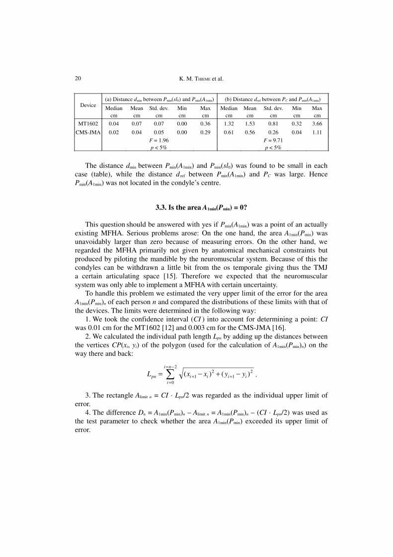
Table. The statistical values for (a) the distance dmin between the point Pmin(sl0) and the point Pmin(A1min)and (b) the distance dref between the point PC and the point Pmin(A1min)
19
K. M. THIEME et al.
Device(a) Distance dmin between Pmin(sl0) and Pmin(A1min) (b) Distance dref between PC and Pmin(A1min)
Mediancm
Meancm
Std. dev.cm
Mincm
Maxcm
Mediancm
Meancm
Std. dev.cm
Mincm
Maxcm
MT1602 0.04 0.07 0.07 0.00 0.36 1.32 1.53 0.81 0.32 3.66
CMS-JMA 0.02 0.04 0.05 0.00 0.29 0.61 0.56 0.26 0.04 1.11F = 1.96p < 5%
F = 9.71p < 5%
The distance dmin between Pmin(A1min) and Pmin(sl0) was found to be small in eachcase (table), while the distance d ref between Pmin(A1min) and PC was large. HencePmin(A1min) was not located in the condyle’s centre.
3.3. Is the area A1min(Pmin) = 0?
This question should be answered with yes if Pmin(A1min) was a point of an actuallyexisting MFHA. Serious problems arose: On the one hand, the area A1min(Pmin) wasunavoidably larger than zero because of measuring errors. On the other hand, weregarded the MFHA primarily not given by anatomical mechanical constraints butproduced by piloting the mandible by the neuromuscular system. Because of this thecondyles can be withdrawn a little bit from the os temporale giving thus the TMJa certain articulating space [15]. Therefore we expected that the neuromuscularsystem was only able to implement a MFHA with certain uncertainty.
To handle this problem we estimated the very upper limit of the error for the areaA1min(Pmin)n of each person n and compared the distributions of these limits with that ofthe devices. The limits were determined in the following way:
1. We took the confidence interval (CI ) into account for determining a point: CIwas 0.01 cm for the MT1602 [12] and 0.003 cm for the CMS-JMA [16].
2. We calculated the individual path length Lpn by adding up the distances betweenthe vertices CP(xi, yi) of the polygon (used for the calculation of A1min(Pmin)n) on theway there and back:
21
21
2
0
)()( iiii
ni
ipn yyxxL −+−= ++
−=
=� .
3. The rectangle Alimit n = CI · Lpn/2 was regarded as the individual upper limit oferror.
4. The difference Dn = A1min(Pmin)n – Alimit n = A1min(Pmin)n – (CI · Lpn/2) was used asthe test parameter to check whether the area A1min(Pmin) exceeded its upper limit oferror.
20
Is a “movable hinge axis” used by the human stomatognathic system?
a) b)
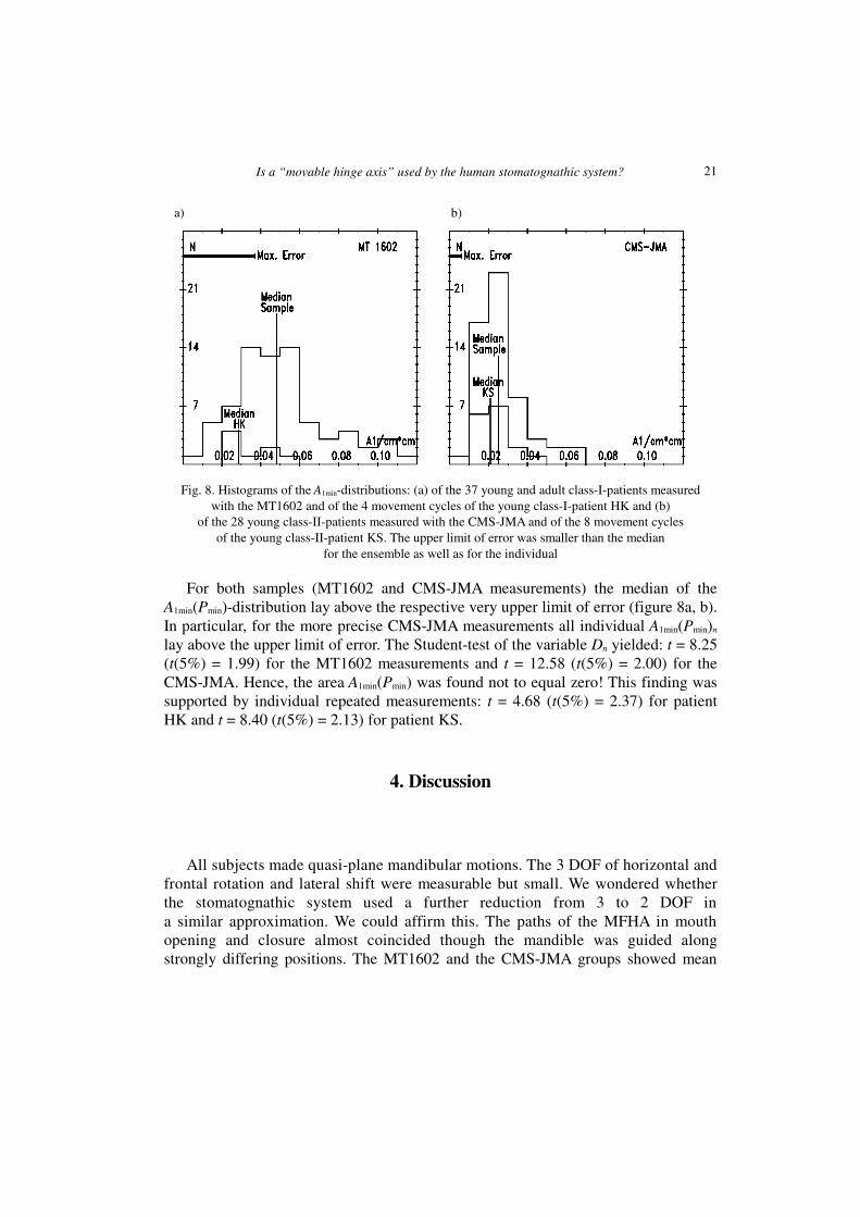
Fig. 8. Histograms of the A1min-distributions: (a) of the 37 young and adult class-I-patients measuredwith the MT1602 and of the 4 movement cycles of the young class-I-patient HK and (b)
of the 28 young class-II-patients measured with the CMS-JMA and of the 8 movement cyclesof the young class-II-patient KS. The upper limit of error was smaller than the median
for the ensemble as well as for the individual
For both samples (MT1602 and CMS-JMA measurements) the median of theA1min(Pmin)-distribution lay above the respective very upper limit of error (figure 8a, b).In particular, for the more precise CMS-JMA measurements all individual A1min(Pmin)n
lay above the upper limit of error. The Student-test of the variable Dn yielded: t = 8.25(t(5%) = 1.99) for the MT1602 measurements and t = 12.58 (t(5%) = 2.00) for theCMS-JMA. Hence, the area A1min(Pmin) was found not to equal zero! This finding wassupported by individual repeated measurements: t = 4.68 (t(5%) = 2.37) for patientHK and t = 8.40 (t(5%) = 2.13) for patient KS.
4. Discussion
All subjects made quasi-plane mandibular motions. The 3 DOF of horizontal andfrontal rotation and lateral shift were measurable but small. We wondered whetherthe stomatognathic system used a further reduction from 3 to 2 DOF ina similar approximation. We could affirm this. The paths of the MFHA in mouthopening and closure almost coincided though the mandible was guided alongstrongly differing positions. The MT1602 and the CMS-JMA groups showed mean
21
K. M. THIEME et al.
residual areas of ~0.048 cm² and ~0.025 cm², respectively, and path lengths of ~3.75cm and ~2.09 cm. Hence the spacing between back and forth (0.048 cm2 / 3.75 cm =0.013 cm and 0.025 cm2 / 2.09 cm = 0.012 cm, respectively) corresponded to thebreadth of a thin pencil line. Therefore the neuromuscular systems were able todifferentiate the entire ensemble of open mouth positions with high precision despiteusing practically 2 DOF. The mandibular positions could be definitely specified by twovariables, the arc length L covered by the MFHA and the rotational angle � in relationto the maxilla (figure 2). Thus an orthogonal coordinate system is obtained in which theensemble of the possible positions of the rigid body is defined one-to-one. This systemis independent of the coordinate system of the measuring apparatus and inherent in thestomatognathic system. It makes intra- and interindividual comparisons of mandibularmovements possible and easy. Especially the structure of the guidance by thestomatognathic neuromuscular system can be evaluated when the mandible was broughtfroma starting to a final position [17].
Since according to Steiner the ensemble of the functions A2(x, y) = constant have torepresent concentric circles and since we found in the most cases that A2(x, y) = 0could be replaced by a straight line (sl0), the Steiner centre lay far away from themandible. In the few cases having a nearer Steiner centre, the search for Pmin(A1min)required additional computational steps.
The existence of A2(x, y) = 0 is common to plane kinematics with 3 DOF. It doesnot imply that a mandibular point Pmin must exist whose absolute area A1(Pmin) equalszero. A1(Pmin) = 0 is the criterion of plane movements with 2 DOF. The residualA1(Pmin) characterizes the approximation of the measured movements to planemovements with 2 DOF. It was found to be close.
The data of the few patients with lacking precision and poor reproducibility inusing the MFHA and having high residuals A1min(Pmin) gave hints that these patientshave hidden problems with their neuromuscular apparatus. In this regard our methodto evaluate in vivo the patients’ MFHA yields a novel diagnostic tool of clinical valueby determining the area A1min(Pmin).
5. Conclusions
Though an ideal MFHA could not be found, we could show that the stomatognathicsystem normally adjusts and uses a MFHA with a surprisingly high precision to guidethe mandible’s position in the case of mouth opening and closing by using only 2 mainDOF. Thus an inherent coordinate system of mandibular movements can be determined.
The mathematical procedure for finding out the inherent coordinate system can beused for quasi-plane movements of other joint systems by analogy.
22
Is a “movable hinge axis” used by the human stomatognathic system?
Acknowledgements
The authors wish to thank Professor Rainer Schwestka-Polly who did all the measurements with theMT1602. This work was supported by a grant from the Deutsche Forschungsgemeinschaft (SCHW 427/2-1, 2-2, and KU 535/6-3, respectively) and is permitted by the ethical commission (8/10/02).
References
[1] YUSTIN D. C., RIEGER M. R., MCGUCKIN R. S., CONNELLY M. E., Determination of the existence of hingemovements of the temporomandibular joint during normal opening by Cine-MRI and computationaldigital addition, Journal of Prosthodontics, 1993, Vol. 2 (3), pp. 190–195.
[2] NAEIJE M., HUDDLESTON-SLATER J. J., LOBBEZOO F., Variation in movement traces of the kinematic centerof the temporomandibular joint, Journal of Orofacial Pain, 1999, Vol. 13 (2), pp. 121–127.
[3] TRAVERS K. H., BUSCHANG P. H., HAYASAKI H., THROCKMORTON G. S., Associations between incisor andmandibular condylar movements during maximum mouth opening in humans, Archives of OralBiology, 2000, Vol. 45 (4), pp. 267–275.
[4] NAGY W. W., SMITHY T. J., WIRTH C. G., Accuracy of a predetermined transverse horizontalmandibular axis point, Journal of Prosthetic Dentistry, 2002, Vol. 87 (4), pp. 387–394.
[5] LE PERA F., Determination of the hinge axis, Journal of Prosthetic Dentistry, 1967, Vol. 14, pp. 651–666.
[6] BOSMAN A. E., Hinge axis determination of the mandible, PhD Thesis, Utrecht, The Netherlands,1974.
[7] HELLSING G., HELLSING E., ELIASSON S., The hinge axis concept: a radiographic study of its relevance,Journal of Prosthetic Dentistry, 1995, Vol. 73 (1), pp. 60–64.
[8] FERRARIO V. F., SFORZA C., MIANI A. Jr., SERRAO G., TARTAGLIA G., Open–close movements in the humantemporomandibular joint: does a pure rotation around the intercondylar hinge axis exist? Journal ofOral Rehabilitation, 1996, Vol. 23 (6), pp. 401–408.
[9] MORNEBURG T., PRÖSCHEL P. A., Differences between traces of adjacent condylar points and theirimpact on clinical evaluation of condyle motion, International Journal of Prosthodontics, 1998, Vol.11 (4), pp. 317–324.
[1] NÄGERL H., KUBEIN-MEESENBURG D., SCHWESTKA-POLLY R., THIEME K. M., FANGHÄNEL J., MIEHE B.,Functional condition of the mandible: physical structures of free mandibular movement, Annals ofAnatomy, 1999, Vol. 181, pp. 41–44.
[2] POSSELT U., Studies in the mobility of the human mandible, Acta Odontology Scandinavia, 1952, Vol.10 (10), pp. 13–150.
[3] KLAMT B., NÄGERL H., KUBEIN-MEESENBURG D., Vergleichende Untersuchung von Meßmethoden zurAufzeichnung der räumlichen Mandibulabewegung (summary in English), Deutsche ZahnärztlicheZeitung, 1990, Vol. 45, pp. 33–35.
[4] BLASCHKE W., MÜLLER H. R., Ebene Kinematik, V. R. Oldenbourg, München, 1956, p. 115.[5] PRESS W. H., FLANNERY B. P., TEUKOLSKY S. J., VETTERLING W. T., Numerical Recipes in C – The Art of
Scientific Computing, Cambridge University Press, Cambridge, UK, 1988, pp. 290–353.[6] KUBEIN-MEESENBURG D., NÄGERL H., KLAMT B., The biomechanical relation between incisal and
condylar guidance in man, Journal of Biomechanics, 1988, Vol. 21 (12), pp. 997–1009.[7] HUGGER A., BÖLÖNI E., BERNTIEN U., STÜTTGEN U., Accuracy of an ultrasonic measurement system for a
jaw movement recording, Proceedings of the IADR/CED 35th Annual Meeting, Montpellier, 1999.
23

K. M. THIEME et al.
[8] NÄGERL H., KUBEIN-MEESENBURG D., FANGHÄNEL J., THIEME K. M., KLAMT B., SCHWESTKA-POLLY R.,Elements of a general theory of joints. 6. General kinematical structure of mandibular movements,Anatomischer Anzeiger, 1991, Vol. 173, pp. 249–264.
24


![Effects of Swimming on Stomatognathic System · 2015-11-30 · facial massive [10]. The stomatognathic system is influenced, in its structure, both from the posture and that to the](https://img.pdfslide.net/doc/110x75/5ed56137af7bb91afb29b492/effects-of-swimming-on-stomatognathic-system-2015-11-30-facial-massive-10-the.jpg)