Embed Size (px)
DESCRIPTION
Indian standard for fire safety design in building.
Citation preview

Disclosure to Promote the Right To Information
Whereas the Parliament of India has set out to provide a practical regime of right to information for citizens to secure access to information under the control of public authorities, in order to promote transparency and accountability in the working of every public authority, and whereas the attached publication of the Bureau of Indian Standards is of particular interest to the public, particularly disadvantaged communities and those engaged in the pursuit of education and knowledge, the attached public safety standard is made available to promote the timely dissemination of this information in an accurate manner to the public.
इंटरनेट मानक
“!ान $ एक न' भारत का +नम-ण”Satyanarayan Gangaram Pitroda
“Invent a New India Using Knowledge”
“प0रा1 को छोड न' 5 तरफ”Jawaharlal Nehru
“Step Out From the Old to the New”
“जान1 का अ+धकार, जी1 का अ+धकार”Mazdoor Kisan Shakti Sangathan
“The Right to Information, The Right to Live”
“!ान एक ऐसा खजाना > जो कभी च0राया नहB जा सकता है”Bhartṛhari—Nītiśatakam
“Knowledge is such a treasure which cannot be stolen”
“Invent a New India Using Knowledge”
है”ह”ह
IS 1642 (1989): Code of practice for fire safety ofbuildings (general): Details of construction [CED 36: FireSafety]


Indian Standard
IS 1642 : 1989 ( Rdkmd 1991)
FIRE SAFETY OF BUILDINGS (GENERAL):DETAILS OF CONSTRUCTION-
CODE OF PRACTICE
/ First Revision ) _~~ ~_
First Reprint OCTOBER 1998
UDC 699.812 : 11
@ BIS 1990
BUREAU OF INDIAN STANDARDS MANAK BHAVAN, 9 BAHADUR SHAH ZAFAR MARG
NEW DELHI 110002
March 1990 Price Group 7

Fire Safety Sectional Committee, BDC 36
FOREWORD
This Indian Standard ( First Revision j was adopted by the Bureau of Indian Standards on 20 June 1989, after the draft linalized by the Fire Safety Sectional Committee had been approved by the Civil Engineering Division Council.
The technical interpretation of fire safety of buildings is to convey the tire resistance of buildings in terms of hours when subjected to a fire of known intensity. The fire grading of the building itself’ enables the correct amount of storage and class of materials, or appropriate ‘fire load’ to be apportioned for that particular application; the converse also holds good, thus, a building being required to accommodate a particular fire load for a given period would require the shell or fabric materials and construction to be designed accordingly.
Loss of life in tires is mainly due to smoke and hot gases being inhaled by occupants before actural flames have devclopcd to a serious degree within the room concerned. Smoke and hot gases spread through doorways and ventilators which are normally impossible to keep closed. The essential requircmenls for lire safety in so far as materials and details of construction are concerned, arc that the flamr smoke and hot gases should not spread so rapidly as to give the occupants insufficient time to escape. Should a fire occur, the construction should not further tend to spread the fire.
In order to reduce spread of fire, it is necessary that:
a) the fire should not spread rapidly from one room to another through the floors, partitions between rooms, and particularly between rooms and passages and staircases, that is, the
‘structural elements should have adequate fire resistance; and
b) the naterials which are exposed to possible ignition, that is, wall and ceiling linings should not easily ignite, nor should the iire spread rapidly over the surface of the materials.
With a view to cover these aspects, this standard dealing with details of construction was first formulated in 1960. This revision has been based on useful information collcctcd as a result of research in the country and abroad over the past 23 years.
The provisions given in this standard are those which are necessary at the time of construction of building new or addition or alterations for adopting fire safety measures. The provisions are applicable for all types of buildings including high rise buildings ( above 15 m in height ). ‘I& standard does not include othrr fire sarcty measures required to be adopted in the buildings of various occupancica in respect ot’ provision of first-aid, fire fightingmeasurzs. alarm and extinguishing systems, operation of tire lifts, ctc; demils of which arc covered in relevant lndian Standards formulated/under formultitioo for each type of occupancy.
For the purpose of deciding whether a particular requirement of this standard is complied with, the final value, observed or calculated, expressing the result of a test or analysis, shall be rounded ofi in accordance with 1S 2 : 1960 ‘Rules for rounding 017 numerical values ( revj& j’. The number of significant places retained in the rounded off value should be the same as that of the specified value in this standard.

IS 1642 : 1989
Indian Standard
FIRE SAFETY OF BUILDINGS (GENERAL):DETAILS OF CONSTRUCTION-
CODE OF PRACTICE
( First Revision )
1 SCOPE
1.1 This standard lays down the essential requirements of fire safety of buildings with respect to details of construction.
2 REFERENCES
The following Indian Standards are necessary adjuncts to this standard:
IS No.
IS 655 : 1963
IS 941 : 1985
IS 1644 : 1988
IS 1646: 1982
1s 3809 : 1979
IS 435s : 1977
IS 12459 : 1988
IS 12777 : 1989
Title
Specification for metal air ducts
Specification for blower and exhauster for fire fighting (second revision )
Code of practice for fire safety of buildings ( general ) : Exit requirements and personal hazard (jet revision )
Code of practice for fire safety of buildings ( general ) : Electri- cal installation (first revision )
Fire resistance test of structure ( jirst revision )
Specification for fire-resistant brattice cloth ( jirst revision )
Code of practice for fire protec- tion of cable runs
Fire safety - Flame spread of products - Methods for classification
3 TERMINOLOGY
3.0 For the purpose of this standard, the definition of various terms will be as under.
3.1 Fire Resistance
Ability of an element of building construction, component for structure to fulfil, for a stated period of time, the required stability, fire integrity and/or thermal insulation and/or other expected duty in a standard fire resistance test ( see 1s 3809 : 1979 ).
3.2 Fire Separation
The distance in metres measured from any other building on the site, or from other site or from
the opposite side of street or other public space to the building for the purpose of preventing the spread of fire.
3.3 Fire Resisting Wall
The wall, either load bearing or non-load bearing. capable of specifying the criteria of fire resistance ( see 3.2 ) with respect to collapse, penetration and excessive temperature rise.
3.4 Separating Wall
The wall provides complete separation of one building from another or part of a building from another part of the same building to prevent any communication of fire or any access or heat transmission to wall itself which may cause or assist in the combustion of materials of the side opposite to that portion which may be on fire.
3.5 Venting Fire
The process of iuducting heat and smoke to leave a building as quickly as possible by such paths that lateral spread of fire and heat is checked, fire figh!ing operations are facilitated and minimum fire damage is caused.
4 TYPES OF CONSTRUCTION
4.0 General
The design of any building and the type of materials used in its construction are important factors in making the building resistant to a complete burn-out and in preventing the rapid spread of fire, smoke or fumes, which may otherwise contribute to the loss of lives and property.
4.1 The types of construction according to fire resistance are classified into four categories, namely, Type I, Type 2, Type 3 and Type 4 construction. The fire resistance ratings for various types of construction for structural and non-structural members should be as given in Table 1.
4.2 For buildings above 15 m in height non- combustible materials should be used for cons- truction and the internal walls of staircases should be of brick work or reinforced concrete or any other material of construction with min-i mum of 2 hours rating. The walls for the
1

I!3 1642 : 1989
chimney shall be of Type 1 or Type 2 construc- tion depending upon whether the gas tempera- ture is above 200 “C or less.
4.3 The fire resistance of an element of structure or combination of elements is determined from one of the following three methods. The fire test is done according to IS 3809 : 1979.
a>
W
4
Information as established by research data ( see Note ).
Direct application of the results of fire resistance test on an element of structures. On the basis for calculating the fire resistance of a structural element. ( This method is not applicable to columns or walls. )
5 WALLS
NOTE - In the absence of research data available in this country, the data as arrived by Building Research Establishment ( UK ) ( see Guidelines for the Construction of Fire Resisting Structural Ele- ments ) has been adopted in this standard. Thercfcrc, while using this data it may be ensured that the specification of material of construction are same as adopted in this Report. However, as and when data from indigenous source is available, the same.will be incorporated in the standard.
5.1 The fire ratings of some types of constructions for walls ( see Note below 4.3 ) are given in Tables 2 to 7. The specifications of materials should be so selected as to give these ratings.
Table i Fire Resistance Ratings of Structural Elements ( in Hours )
( Clu~ses 4.1 atrd 5.10 )
SI No. r---
Structural Element Type of Construction _*-.----____, ~~~-~~~~_~___
1
10 Structural members support walls
II Floor construction including walls
12 Roof construction
Exterior walls:
a) Fire separation less than 3.7 m
b) Fire separation of 3.7 m or more but less than 9 m
c) Fire separation of 9m or more
Fire walls
Fire separation assemblies ( like fire check doors )
Fire enclosures of exitways, exit- way hallways, and stairways
Shaft other than exitways elevator hoistways
Exitway access corridors
Vertical separation of tenant spaces
Dwelling unit separation Non-load b-earing partitions
Interior bearing walls, bearing partitions,columns, girders, trusses ( other than roof trusses ) and framing
i) Bearing ii) Non-bearing
i) Bearing ii) Non-bearing
i) Bearing ii) Non-beariug
i) Supporting more than one floor
_ii) -Supporting one floor only
iv) Supporting a roof ‘only
i) 5 m or less in height to lowest member
ii) More than 5 m but less than 6.7 m in height to lowest member
iii) 6’7 m or more in height to lowest member
Type 1 Type 2 Type 3 Type 4
2” f* 4 1
4
4
2
2
1
1
1 t At
4
3
3
8, 2 I
2 2 1 I
2 2 1 1
2 2
2 2
2 2
2 2
1 1
1 1
1 least half lan
2 2
1) 1
lb 1
1) 1
li 1
I9 1
1 1
0 0
2
2
1
1
hour:
2
1
1
2

IS 1642 : 1989
Table 2 Masonry Walls: Solid ( Required to Resist Fire from One Side at a Time )
( Clause 5.1)
Nature of Constructioo and Materials Minimum Thickness (mm), Excluding any Finish, for a Fire Resistance (Hours ) of
-- 1
120 (25) 150
Load Bearing *---__-7
4
240 (25) -
It
140 (25) 175
100 90
100 90
100 90
100 90
100 90
2
(i$ -
100 90
100 90
100 90
100 90
100 IO0
3
6: -
170 100
190 100
loo
140 100
140 100
1 Reinforced* cement concrete
2 Unreinforced cement concrete 3 No-fines concrete with:
a) I3 mm cementlsand or gypsum/sand b) ;fa;; hghtwelght aggregate gypsum
4 Bricks of clay: a) Without finish b) With 13 mm lightweight aggregate
gypsum plaster 5 Bricks of sand lime:
a) Without finish b) With 13 mm lightweight aggregate
gypsum plaster 6 Blocks of concrete:
a) Without finish b) With 13 mm lightweight aggregate
gypsum plaster c) ya;it_” mm cement/sand or gypsum/
7 Blocks of lightweight concrete: a) Without finish b) With 13 mm lightweight aggregate
gypsum plaster c) With 13 mm cementisand or gypsum/
sand 8 Blocks of aerated concrete:
a) Without finish b) With 13 mm lightweight aggregate
gypsum plaster
90 90
;x 90 SO
90 90
*Walls containing at least 1 percent of vertical reinforcement. ( ) Minimum thickness of actual cover to reinforcement.
170 100
190 100
lo0
I50 100
180 150
Non-Load Bearing ’ _-I_-_--A--__
1
150 150
75 7.5
75 75
75 75
75
75 50
75
50
150 I50
2
150 150
100 90
90 :0
100 90
90 75
90
100 75
SO
75 75 63 75
75 75
63 63
3
150 150
170 90
170 90
140 90
100
125 75
90
75
4
150 150
170 IO0
170 100
150 100
140
I40 75
100
100
Table 3 Masonry Walls: Hollows (Required to Resist Fire from One Side at a Time)
(Clause 5.1 )
Nature of Construction and Materials Minimum Thickness ( mm ), Excluding any Finish, for a Fire Resistance ( Hours ) of
r------------ h---___________
Load Bearing Non-Load Bearing __---- ____- ~ r ---___ -h_-______~ 1 l!, 2 3 4 : 1 1: 2 3 4
1 Bricks of clay: a), Without finish b) With 13 mm lightweight aggregate
gypsum plaster 2 Bjock’s of concrete:
a) Without finish b) With 13mm cement/sand or gypsum!
sand c) With 13 mm lightweight aggregate
gypsum plaster 3 Blocks of lightweight concrete:
a) Without finish b) Wi;i 13 mm cement/sand or gypsum/
c) With 13 mm lightweight aggregate gypsum plaster
170 170 170 200 200 75 100 100 100 100 170 170 170 75 75 90
90 125 125 90 125 I25
190 200 200 - - 75 90 90
100 100 100 - - ;: 90 75 7’:
63 63 75
170 100
140 140
100
100 100
75
170 200 100 170
125 125
140 150 140 140
90 100
3
IS 1642 : 1989
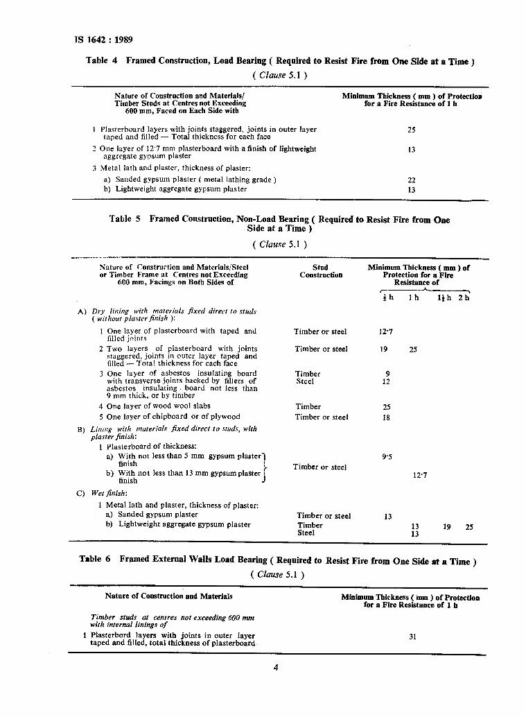
Table 4 Framed Construction, Load Bearing ( Required to Resist Fire from One Side at a Time )
( Clause 5.1 )
Nature of Construction and Materials/ Timber Studs at Centres not Exceeding
Minimum Thickness ( mm ) of Protection for a Fire Resistance of 1 h
600 mm, Faced on Each Side with
1 Plasterboard layers with joints staggered, joints in outer layer taped and filled - Total thickness for each face
3 One layer of 12’7 mm plasterboard with a finish of lightweight aggregate gypsum plaster
25
13
3 Metal lath and plaster, thickness of plaster:
a) Sanded gypsum plaster ( metal lathing grade ) b) Lightweight aggregate gypsum plaster
22 13
Table 5 Framed Construction, Non-Load Beariug ( Required to Resist Fire from One Side at a Time )
( Clause 5.1 )
Nature of ronstrurtion and Materials/Steel or Timber Frame at Centres not Exceeding
600 mm, Facings on Botb Sides of
A) Dry lining with materials fixed direct to studs ( without plasrer finish ):
I One layer of plasterboard with taped and filled joints
2 Two layers of plasterboard with joints staggered, joints in outer layer taped and filled - Total thickness for each face
3 One layer of asbestos insulating board with transverse joints backed by fillers of asbestos insulating board not less than 9 mm thick, or by timber
4 One layer of wood wool slabs
5 One layer of chipboard or of plywood
B) Lining with materials fixed direct to studs, with plaster finish:
1 Plasterboard of thickness: a) yniitinot less than 5 mm gypsum plaster]
b) Tj;:hnot less than 13 mm gypsum plaster i
1
C) Wet finish:
1 Metal lath and plaster, thickness of plaster: a) Sanded gypsum plaster b) Lightweight aggregate gypsum plaster
Stud Construction
Minimum Thickness ( mm ) of Protection for a Fire
Resistance of
Timber or steel 127
Timber or steel 19 25
Timber Steel
Timber 25 Timber or steel 18
Timber or steel
1;
9.5
12.7
Timber or steel Timber Steel
13
:: 19 25
Table 6 Framed External Walls Load Bearing ( Required to Resist Fire from One Side at a Time )
( Clause 5.1 )
Nature of Construction and Materials Minimum Thickness ( ium ) of Protection for a Fire Resistance of 1 II
Timber studs at centres not exceeding 600 mm with internal linings of
1 Plasterbord layers with joints in outer layer taped and filled, total thickness of plasterboard
31
4
IS 1642 : 1989
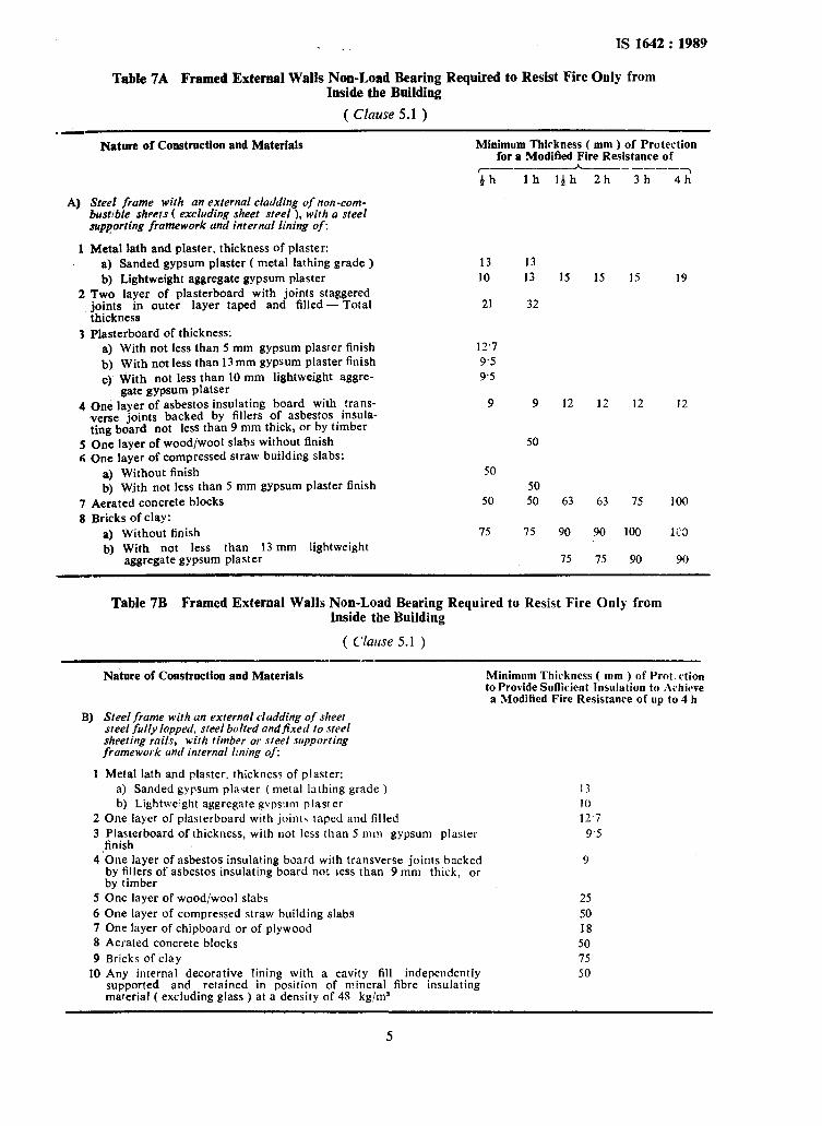
Table 7A Framed External Walls Non-Load Bearing Required to Resist Fire Only from Inside the Building
( Clause 5.1 )
4
1
Nature of Construction and Materials Minimum Thirkness ( mm ) of Protection for a Modified Fire Resistance of
_~_--_~ -- ----_ ‘th lh lth 2h 3h
Steel frame with an external cladding of non-com- bustfble sheets ( excluding sheet steel ), with a steel supporting framework and internal lining of:
Metal lath and plaster, thickness of plaster: a) Sanded gypsum plaster ( metal lathing grade ) b) Lightweight aggregate gypsum plaster
13 13 10 13 15 15 15
2 Two layer of plasterboard with joints staggered joints in outer layer taped and filled - Total thickness
3 Plasterboard of thickness: a) With not less than 5 mm gypsum plaster finish b) With not less than 13 mm gypsum plaster finish C) With not less than 10 mm lightweight aggre-
gate gypsum platser 4 One layer of asbestos insulating board with Jrans-
verse joints backed by fillers of asbestos. msula- ting board not less than 9 mm thick, or by timber
5 One layer of wood/wool slabs without finish 6 One layer of compressed straw building slabs:
a) Without finish b) Wjth not less than 5 mm gypsum plaster finish
7 Aerated concrete blocks 8 Bricks of clay:
a) Without finish b) With not less than 13 mm lightweight
aggregate gypsum plaster
21 32
12’7 9’5 9.5
9 9
50
50 50
50 50
75 15
12 12
63 63
90
75
90
75
12
15
100
90
4h’
19
12
100
1C3
90
Table 7B Framed External Walls Non-Load Bearing Required to Resist Fire Only from Inside the Building
( Cluwe 5.1 )
Nature of Construction and Materials Minimum Thickness ( mm ) of Prot:rtion to Provide Sufficient lnsulation to L\<hicave a Modified Fire Resistance of up to 4 h
B) Steel frame with an external cladding of sheet steel fully lapped, steel bolted andfixed 10 steel sheeting rails, wirh timber or steel supporting framework und internal lining of:
I Metal lath and plaster. thickness of plaster: a) Sanded gypsum platter ( metal lathing grade ) b) Lightweight aggregate gvpsum plaster
2 One layer of plasterboard with joints taped and filled 3 Plasterboard of thickness, with not less than 5 mm gypsum plaster
,finish 4 One layer of asbestos insulating board with transverse joints backed
by fillers of asbestos insulating board no! less than 9 mm thick, or by timber
5 One layer of wood/wool slabs 6 One layer of compressed straw building slabs 7 One layer of chipboard or of plywood 8 Aerated concrete blocks 9 Bricks of clay
10 Any internal decorative lining with a cavity fill independently supported and retained in position of mineral fibre insulating material ( excluding glass ) at a density of 48 kg/m3
13 I 0 12.7
9.5
9
25 50 18 50 75 50
5

1s 1642 : 1989
Table 7C Framed Walls Non-Load Bearing Required to Resist Fiie Only from Inside the Building
( Clause 5.1 )
Nature of Construction and Materials Minimum Thickness ( mm ) of Protection for a Fire Resistance of I$ II
1 i’lasterboard not less than ‘j.5 mm thick, finished with:
a) Gypsum plaster b) Lightweight aggregate g> psum plaster
2 Plasterboard not less than 12’7 mm thick, finished with:
a) Gypsum plaster bj Lightweight aggregate gypsum plaster
3 One layer of asbestcs insulating board with transverse joints backed by fi!lers of ashes!os insulating board not less than 9 mm thick, or by timber
13 10
10 10
1’2
5.2 The separating walls should be carried through the roof to a height of at least 60cm above except in the case of reinforced brick/ concrctc slab roof where it should be bonded flash ,with a top level of the slab. At the time cjf designing openings, particular attention should be paid to all such factors as will limit fire spread through these openings. Every opening in the wall should be protected by fire resisting doors having the fire rating of not less than 1 hour. Similar protection should also be done in other openings like rope races, motor alley ways, staircases. etc. of rating not less than 2 hours. However, for Types 1, 2. 3 construction, a doorway or opening in a separating wall of any floor should be limited to 5.6 1112 in area with a maximum height of 2.75 m al:d maximum width of 2 m.
5.3 When building(s) and/or c;mpartment(s) are separated by separating wall(s) and there is a rerand~!/z 011 one or more sides of such building(s) and/or compartment(s), it is necessary that the separating wall should be built out across the verandulz and be carried through the roof of the same; otherwise the building(s) and/or compartment(s) should be regarded as having internal communication and, therefore, subject to danger of spread of fire.
5.4 When opening in walls are provided to allow cable, etc, the space around cables and the wall should be protected according to the provision given in IS 12459 : 1988. However, such space in case of openings provided to allow plumbing/ gas,/stc~am pipes and similar services should be sealed with iii!er material of fire rating not less than that of the walls in which these are situated.
5.5 Where openings are permitted, they should not exceed three-fourths of the area of the wall in case of an external wall.
6
5.6 A separating wall should be supported in a vertical line by a similar separating wall through all storeys below. The separating wall should be carried and bonded to the floor of appropriate fire-resisting construction.
5.7 When a separating wall runs parallel to the axis of the north light opening or gabled roof, the screen wall should be carried through, and 60 cm above the top of the north light opening except in cases where the screen wall becomes of such a height that horizontal distance between the north light opening and the roof of the adjoining building and/or compartment or between two sloping faces of the two consecutive roofs at the level of the top of the screen wall, is at least 6 m.
If, however, the separating wall is at right angles to the axis of the north light opening or the gabled roof, the ‘saw tooth? gaps should be bricked up and screen wall extended above the ridge of the north light or the gabled roof.
5.8 All separating walls should be built out to extend 15 cm beyond the eaves of the roof so as to effectively cut off the roofs of the parts so separated. The eaves should be cut away on each side of this extension of the separat- ing wall. If there is an opening on both sides of the separating wall within 3 m of the wall, those on one side should be bricked up to full thickness of wall, or an alternative should be provided with fire resisting doors of fire rating not less than of 2 hours for walls of 4 hours rating and 1 hour for other rating. 5.9 Common wooden roof members (trusses, joists and purlins) should not pass through the separating walls but they may be embedded there- in provided they do not extend more than 22.5cm into wall and are separated from the similar roof member in the adjoining building by at least 11 cm or solid wall material.

X31642:1989
5.10 Partition is used for separating sections or rooms of a building but is not expected to have a fire resistance equa1 to any of the values. In fact, in practice it should not be considered other- wise than structure of light dimension and stren- gth consistent with the purpose for which it is used. The minimum fire rating of the parti- tion is given in Table 1.
6 COLUMNS AND BEAMS
6.1 The fire ratings of some types of construction
are given in Tables 8, 9, 12 and 13 ( see Note below 4.3 ). The specifications of materials should be so selected as to give these ratings.
7 FLOORS AND ROOFS
7.1 The fire ratings of some types of construction is given in Tables 10, 11, 14, 15, and 16. The specifications of materials should be so selected so as to give these ratings.
Table 8 Reinforced Concrete Columns
( Cfuuse 6.1 )
Nature of Construction and Materials Minimum Dimensions ( mm ), Excluding any Finish, for a Fire Resistance of
r ______- -__-p__- th lh l$h 2h 3h -T 4h
1 Fully exposed Width 150 200 250 300 400 450 Cover 20 25 30 35 35 35
2 50 percent exposed Width 125 160 200 200 300 350 Cover 20 25 25 25 30 35
3 One face exposed Thickness 100 120 140 160 200 240 Cover 20 25 25 25 25 25
Table 9 Concrete Beams
( Clause 6.1 )
Nature of Construction and Materials
1 Reinforced concrete ( simply supported ) Width Cover
2 Reinforced concrete ( continuous ) Width Cover
3 Prestressed concrete ( simply supported > Width Cover
4 Prestressed concrete ( continuous ) Width Cover
Minimum Dimensions ( mm ), Excluding any Finish, for a Fire Reshtance of
C--‘ --..--h-_----_----~ +h lh l&h 2h 3h 4h
80 120 150 200 240 280 20 30 40 60 70 80
80 SO 120 150 200 240 20 20 35 50 60 70
100 120 150 200 240 280 25 40 55 70 80 90
80 100 120 150 200 240 20 30 40 55 70 80
Table 10 Concrete Floors
( Clause 7.1 )
Minimum Dimensions (mm ), Excluding any Finish, Nature of Construction and Materirtls for a Fire Resistance of
P-- h-_---_____
th lh lbh 2h 3h 4h
1 Reinfoiced concrete ( simply supported ) Thickness 75 95 110 125 150 170 Cover I5 20 25 35 45 55
2 Reinforced concrete ( continuous ) Thickness 75 95 110 125 is0 170 Cover 15 20 20 25 35 45
7
1s 1642 : 1989
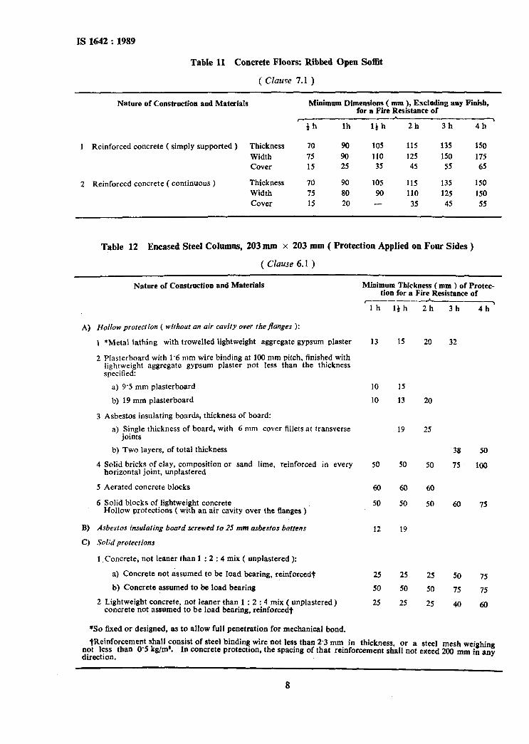
Table 11 Concrete Floors: Ribbed Open Sofflt
( CIuuYe 7.1 )
Nature of Construction and Materials
r
1 Reinforced concrete ( simply supported ) Thickness
Width Cover
2 Reinforced concrete ( continuous ) Thickness Width Cover
Minimum Dimensions ( mm ), Excluding any Finish, for a Fire Resistance of
G lh A
lhh 2h 3h 4h
70 90 105 115 135 150
75 90 110 125 150 175 15 25 35 45 55 65
70 90 105 115 135 150
?5 80 90 110 125 150
15 20 - 35 45 55
Table 12 Encased Steel Cohnns, 203 mm x 203 mm ( Protection Applied on Four Sides )
( Clause 6.1 )
Nature of Construction and Materials
A) Hollow protection ( without an air cavity over thejlanges ):
1 *Metal lathing with trowelled lightweight aggregate gypsum plaster
2 Plasterboard with 1.6 mm wire binding at 100 mm pitch, finished with lightweight aggregate gypsum plaster not less than the thickness specified:
a)‘9-5 mm plasterboard
b) 19 mm plasterboard
3 Asbestos insulating boards, thickness of board:
a) Single thickness of board, with 6 mm cover fillets at transverse joints
b) Two layers, of total thickness
4 Solid bricks of clay, composition or sand lime, reinforced in every horizontal joint, unplastered
5 Aerated concrete blocks
6 Solid blocks of lightweight concrete Hollow protections ( with an air cavity over the flanges )
B) Asbestos insulating board screwed to 25 mm asbestos battens
C) Solid protections
1, Concrete, not leaner than 1 : 2 : 4 mix ( unplastered ):
a) Concrete not assumed to be load bearing, reinforced+
b) Concrete assumed to be load bearing
2 Lightweight concrete, not leaner than 1 : 2 : 4 mix ( unplastered) concrete not assumed to be load bearing, reinforcedt
*so fixed or designed, as to allow full penetration for mechanical bond.
Minimum Thickness (mm ) of Protec- tion for a Fire Resistance of
r~--__-h-___, lh 14 h 2h 3h 4h’
13 15 20 32
10
10
15
13 20
19 25
50 50 50
38
75
60
50
60
50
60
50 60
12 19
25 25 25 50
50 50 50 75
25 25 25 40
50
100
75
75
75
60
*Reinforcement shall consist of steel binding wire not less than 2.3 mm in thickness, or a steel mesh weighing not less than 0’5 kg/m*. direction.
In concrete protectlon, the spacmg of that reinforcement shall not exeed 200 mm in any
8

IS 1642 : 1989
Table 13 Encased Steel Beams, 406 mm x 176 mm ( Protection Applied on Three Sides )
( Clause 6.1 )
A)
B)
C)
Nature of Construction and Materials
HoIlow protection ( without an air cuvity beneath the lower flange ):
1 *Metal lathing with trowelled lightweight aggregate gypsum plaster ( metal lathing grade )
2 Plasterboard with 1.6 mm wire bindingt at 100 mm pitch, finished with lightweight aggregate gypsum plaster not less than the thickness specified:
a) 9.5 mm plasterboard bJ 19 mm plasierboard
3 Asbestos insulating board, thickness of board:
a) Single thickness of board, with 6 mm cover fillets at transverse joints
h) Two layers, of total thickness
Hollow protection ( with an air cuvity below the lower Jkige ): 1 Asbestos insulating board screwed to 25 mm asbestos
battens
Solid protection: 1 Concrete, not leaner than 1 : 2 : 4 mix ( unplastered ):
a) Concrete not assumed to be load bearing, reinforcedt b) Concrete assumed to be load bearing
2 Lightweight concrete§ not leaner than 1 : 2 : 4 ( mix ) unplastered
Minimum Thickness ( mm ) of Protection for a Fire Resistance of
r----- A__._---_---\ th lh l;h 2h 3h 4h
13
10 10
9
:; 25
13 15 20 25
10 15 10 13 20
19 25 38 50
12
*So fixed, or designed, as to allow full penetration for mechanical bond. +Where wire binding cannot be used, expert advice should be sought regarding alternative .methods
of support to enable ihe lower edges of the plasterboard to be fixed together and to the lower flange, and for the top edge of the plasterboard to be held in position.
meinforcement shall consist of steel binding wire not less than 2.3 mm in thickness or a steel mesh weighing not less than 0.5 kg/m*. In concrete protection, the spacing of that reinforcement shall not exceed 200 mm in any direction.
gconcrete not assumed to be load bearing, reinforced.
Table 14 Timber Floors - Tongued and Grooved Boarding, or Sheets of Tongued and Grooved Plywood or Wood Chipboard, of not Less than 21 mm Fished Thickness
( Clause 7.1 )
Nature of Construction and Materials Minimum Thickness (mm) of Protec- tion for a Fire Resistance of
37 mm ( minimlrm ) timber joists with a ceiling of: _---A__.-_
ih lh 2h’
Timber lathing and plaster, plaster of thickness Metal lathing and plaster, thickness of plaster:
a) Sanded gypsum plaster ( metal lathing grade) b) Lightweight aggregate gypsum plaster
One layer of plasterboard with taped and filled joints
Two layers of plasterboard with joints staggered, joints in outer layer taped and filled total thickness One layer of plasterboard not less than 9.5 mm thick, finished with:
a) Gypsum plaster b Sanded gypsum plaster c) Lightweight aggregate gypsum plaster
One layer of plasterboard not less than 12’7 mm thick, finished with: a) Gypsum plaster b) Lightweight aggregate gypsum plaster
One layer of asbestos insulating board with any transverse joints backed by fillets of asbestos insulating board pot less than 9 mm thick, or by timber
15
:: 12-7
19
5
::
1’0 9
13 25
31
12
9

IS1642:1989
Table 15 Timber Floors - Tongued and Grooved Boarding, or Sheets of Tongued and Grooved Plywood or Wood Chipboard, of not Less than 15 mm Finished Thickness
( Clause 7.1 j
Nature of Construction and Materials
37 mm ( minimrrm ) timber joists wirh a ceiling of:
1 Timber lathing and plaster, plaster of thickness
2 Metal lathing and plaster, thickness of plaster for:
a) Sanded gypsum plaster ( metal lathing grade ) b) Lightweight aggregate gypsum plaster
3 One layer of plasterboard with taped and filled joints
4 Two layers of plasterboard with joints staggered, joints in outer layer taped and filled total thickness
Minimum Thickness (mm j of Protection for a Fire
Resistance of _--- --c---T
l;h Ih 2h
15
15 13 13 25
12.7
22 31
5 One layer of plasterboard not less than 9.5 mm thick, finish with:
a) Gypsum plaster 5
b) Sanded gypsum plaster 15 c) Lightweight aggregate gypsum plaster 13
6 One layer of plasterboard not less than 12.7 mm thick, finished with:
a) Gypsum plaster 5
b) Lightweight aggregate gypsum plaster 10
7 One layer of asbestos insulating board. with any transverse joints backed by fillets of asbestos insulating board not less than 9 mm thick, or by timber 9 12*
*Finished on top with 25 mm minimum thick glass fibre or mineral wool laid beetween joints.
Table 16 Timber Floors - Any Structurally Suitable Flooring of Timber or Particle Boards
( Clause 7.1 )
Nature of Construction and Materials Minimum Thickness (mm ) of Protection for a Fire
Resistance of r-__h____~
37 mm ( minimum ) timber joists with a ceiling of:
1 Timber lathing and plaster, plaster of thickness
2 Metal lathing and plaster, thickness of plaster for:
a) Sanded gypsum plaster ( metal lathing grade )
b) Lightweight aggregate gypsum plaster
3 One layer of plasterboard with joints taped and filled and backed by timber
4 TWO layers of plasterboard with joints staggered, joints in outer layer taped and filled total thickness
th
15
15 13
12’7
25
Ih
19
Two layers of plasterboard, each not less than 9.5 mm thick, joints between boards staggered and outer layer finished with gypsum plaster
One layer of plasterboard not less than 9.5 mm thick, finished with:
a) Sanded gypsum plaster
b) Lightweight aggregate gypsum plaster
One layer of plasterboard not less than 12.7 mm thick, finished with:
a) Sanded gypsum plaster
b) Lightweight aggregate gypsum plaster
One layer of asbestos insulating board with any transverse joints backed by fillets of asbestos insulating board not less than 9 mm thick, or by timber
5
13 15
I5
13
12
10

7.2 In case of a building more than 15 m in height, all iloors should be compartmented with area not cxcceding 751) m2 by a separation wall with 2 hours fire rating, for floors having provision of sprinklers. The area may be increased bv 50 percent. In long buildings, the fire separation walls should be at distance not exceeding 40 m. For departmental stores, shopping centres and similar occupancies, the area may be reduced to 500 m2. Where this is not possible provision of the sprinklers should be kept with appropriate spacing.
7.3 A surface covering of non-combustible and non-toxic material should be laid directly on the incombustible floor. Wood flooring may be laid directly on such surface covering, or directly on such floor provided that in either case there is no intervening space and that any wood fillets for affixing such flooring is bedded not more than 2.5 cm in the non-combustible floor.
7.4 In the case of building used for storage pur- poses, the floor surface should conform to the above, in addition, it should be at least 15 cm above the ground level or the level of the door sills whichever is higher, and should slant towards the doors.
7.5 An opening through a floor should comply with the following:
At the time of designing openings parti- cular attention should be paid to all such factors which will limit fire spread through these openings.
Whm opening in floors are provided to allow cabie, etc, the space around cable and the floor should be protected accord- ing to th eprovision given in IS 12459 : 1988. However, such space in case of openings provided to allow plumbing/gas/steam pipes and similar services should be sealed with filler material of fire rating not less than 1 hour.
Openings for steam, gas and/or water pipes and electrical conduits, whether of iron or earthenware, should have a radial clearance, to allow for any heat expansion, not greater than 3 mm.
The enclosure for staircases and hoists should be cons;ructcd entirely of brick, concrete or of reinforced concrete or similar material of construction having 2 hours rating. Every opening from the enclosure on to a roof used as floor or to any other part of the building should be fitted with a fire resistant door of rating not less than 1 hour.
If any staircase or hoist extends to the top storey of a building the roof of which is not a roof used as a floor, the enclosing walls should be carried through and at least 45 cm abcvc the reef of the building and
11
IS 1642: : 1989
a skylight or window glazed should be provided above the roof of the building. Alternatively, if the roof of the building is used as a floor. it should comply with (d), and this should also apply for any furnace or motor chamber communicating with the staircase or hoist enclosure.
7.6 Linings or false ceilings should not be permis- sible in buildings and in situations, where permit- ted, such additions should not detract in anyway from minimum fire rating of half an hour.
In some cases, requiring provision of skylights, monitor lights or north lights in the roofs and where thrse are necessary. the glazings should be of glass in metal frames fcr lire rating of half an hour minimum.
7.7 Composite roofs may be used over 3s ad- dition to the roofs of bui!dings as a weathcr- proofing, but should not be considered as a roof in itself. that is, without the sunport of a non- combustible construction beneath, unless it is of not less than half an hour fire resistance.
8 AIR-CONDlTIONENG
8.1 Air-conditioning systems should be so instal- led and maintained as to minimize the danger of spread of fire, smoke or fumes thereby from one floor or lire area to another, or from outside into any occupied building or structure.
8.2 Air-conditioning systems circulating air to more than one floor area should be provid-. ed with dampers designed to close automatically in case of fire and thereby prevent spread of tire or smoke. Such a system should also be provided with automatic controls to stop fans in case of fire, unless arranged to remove smoke from a fire, in which case these should be designed to remain in operation.
8.3 Air-conditioning system serving large places of assembly ( over 1000 persons ), large depart- mental stores or hotels with over 100 rooms in a single block should be provided with elTective means for preventing circulation of smoke through the system in the case of a lire in air filters or from other sources drawn into the system even though there is insufficient heat to actuate heat sensitive devices controlling fans or dampers. Such means should consist of approved effective smoke sensitive controls.
8.4 Air-conditioning should conform to the following:
a)
‘3
Cl
Escape routes like staircases, common corridors, lift lobbies, etc, should not be used as return air passage.
The ducting should be constructed of metal in accordance with IS 655 : 1963.
Wherever the ducts pass through fire walls or floor, the opening around the ducts

IS 1642 : 1989
4
e)
f 1
g>
should be sealed with fire resisting materials of same rating as of walls/floors.
As far as possible, metallic ducts should be used even for the return air instead of space above the false ceiling.
The material used for insulating the duct system ( inside or outside ) should be of flame resistant ( see IS 4355 : 1977 ) and non-conductor of heat.
Area more than 750 m* on individual floor should be seggregated by a fire wall and automatic tire dampers for isolation should be provided.
In case of more than one floor, arrange- ment by way of automatic fire dampers for isolating by ducting at every floor from the main should be made. Where plenu- mus used for return air passage, ceiling and its fixtures and air filters of the air handling units should be flame resistant [ see 8.4 (e)]. Inspection panels should be provided in the main trunking. Nocom- bustible material should be fixed nearer than 15 cm to any duct unless such ducting is properly enclosed and protected with flame resistant material. The fire dampers should be located in conditioned air ducts and return air ducts passages at the following points which will operate auto- matically and are simultaneously switch off air handling fans:
i) at the fire separation wall,
ii) where ducts/passages enter the central vertical shaft,
iii) where the ducts pass through floor, and
iv) at the inlet of supply air duct and the return air duct of each compartment on every floor.
In case of buildings more than 24 m in height in non-ventilated lobbies corridors. smoke extraction shaft should be provided. The automatic tire damper should bc so arranged so as to close by gravity in a direction of movement and to remain tightly closed upon operation.
9 SMOKE AND FIRE VENTING
9.1 Provision has to be made for venting which allows escape of hot gases and smoke release by accidental burning of combustible material stored OT are being processed inside a building, and will give ample time for all the inmates to escape before the roof collapses either in part or whoiiy in the event of fire. Provisions in this regard are essential for industrial buildings; details of which are covered in a separate Indian Standard. The provision in regard to the domestic buildings are given in 9.2. The form of vent should be a venti-
lator-cum-exhaust which in addition to the requisite grading of fire rating be easily openable.
9.2 Smoke venting facilities, where required for safe use of exits in windowless buidings, under- ground structures, large area factories, depart- mental store, domestic dwelling, theatres, cinemas, lecture halls, etc, or *here required should be automatic in action.
9.3 Natural draft smoke venting should utilize roof vents or vents in walls at or near the ceiling level; such vents should be normally open, or if closed, should be designed for automatic opening in case of fire, by release of heat smoke sensitive elements, breakage of glass, or melting of plastic under the influence of heat; or by other approved means.
9.4 Where smoke venting facilities are installed for purposes of exit safety, these should be ade- quate to prevent dangerous accumulation of smoke during the period of time necessary to evaluate the area served, using available exit facilities with a margin of safety to allow for unforeseen contingencies.
9.5 The discharge apertures of all natural draft smoke vents should be so arranged as to be readily susceptible to. opening by fire service personnel.
9.6 Power operated smoke exhausting systems may be substituted for natural draft vents ( see IS 941 : 1985 ).
9.7 In case of buildings more than 15 m in height the staircase should be ventilated to the atmos- phere at each landing and a vent at the top, the vent openings should be 0.5 m in the external wail and top. If the staircase cannot be ventilated because of location or other reasons, the provision shoul~i be made for pressurization ( 50 Pa ) to be separated automatically with the fire alarm. The roof of the shaft in the latter case should bc 1 m
above the surrounding roofs. ‘Glazing or glass bricks should not be used in the staircase.
10 SERF’JCE DUCTS
10.1 Service ducts should be enk,losed by wails and doors ( if any ) of 2 hours fire rating; if ducts are larger than 1 m3 the floor should sea] them, but provide suitable openings for the pipes to pass through, with the gaps sealed.
10.2 A vent opening at the top of the service shaft should be provided between one-fourth and one-half of the area of the shaft.
11 BASEMENTS
11.1 Each basement should be separately venti- 1,ated. Vents with cross-sectional area ( aggre- gate. ) not less than 2.5 percent of the floor area spread evenly round the perimeter of the base- ment should be provided in the form of grills or breakable stallboard lights or pavement lights or
12

by way of shafts. Alternatively, a system of air inlets should be provided at basement floor level and, smoke outlets at basement ceiling level. Inlets and extractors may be terminated at ground level with stallboard or pavement lights as before, but ducts to convey fresh air to the basement floor level have to be laid. Stallboard and pavement lights should be in positions easily accessible to the fire brigade and clearly marked &SMOKE OUTLET’, or ‘AIR INLET’ with an indication of area served at or near the opening.
11.2 The staircase of basements should be of enclosed type having fire resistance of not less than 2 hours and should be situated at the periphery of the basement to be entered at ground level only from the open air and in such positions that smoke from any fire in the base- ment should not obstruct and exit serving the ground and upper storeys of the building and should communicate with basement through a lobby provided with fire resisting self-closing doors of I hour fire resistance. If the travel distance exceeds 18.50 n, additional staircases should be provided at proper placer.
11.3 In multi-level basements, intake ducts may serve aI1 basement levels, but each basement and basement compdrtment should have separate smoke outlet duct or ducts. Mechanical extrac- tors for smoke venting ( see IS 941 : 1985 ) from low basement levels should also be provil ded, with provision of automatic operation of system actuation of heat/smoke sensitive detec- tors or sprinklers and also manully. Mechani- cal extractors should have an inter-locking arrangement, so that extractors should continue to operate and supply fans should stop auto- matically with the actuation of fire detectors. Mechanical extractors should be designed to permit 30 air changes per hour in case of tire or distress call. However, for normal operation, only 28 air changes should be maintained. Mechanical extractors should have an alternative source of supply. Ventilating ducts should be integrated with the structure and made out of brick masonry or RCC as far as possible and when this duct crosses the transformer area or electrical switch board, fire dampers should be provided. Basement/sub-basement should not be used for storage, cooking purposes, garrage and shops unless provision is made for sprinkler system. If cut-outs are provided from basements to the upper floors or to the atmosphere all sides of the cut-out openings in the basements should be protected by automatic spray in the event of a fire.
12 CHIMNEYS
12.1 Over and above the provisions given in 4.2, the following previsions should be followed:
a) A clearance of at least 4 cm between the outer surface of the chimney and any adjacent combustible material forming
b)
C)
d)
4
f j
g>
IS 1642 : 1989
part of a wall lining enclosing the chimney.
The tire resistance of ‘any structure surrounding a flew or flew pipe should be not less than that for external walls. In the case of flew pipe there should be an air space between it and the surrounding structure of sufficient width to permit access to the pipe for inspection and repair.
When a flew pipe passes though any other room or an enclosed roof space it should be protected by structure having a fire resistance equal to the external walls.
The chimney excluding the pot should be carried to a minimum height of 1 m above the highest point of its junction with the roof.
The outlet of a flew from domestic appliance having a roof covering should be at least 2.5 m in a horizontal plain from the roof of any structure built upon the roof or at least 0.6 m higher than any ridge within 2.5 m.
If the roof covering is not fire resistant, no flew outlet should be lower than the ridge for the highest point of the roof or less than 1 m above any ridge within 25 m.
Where a metal chimney passes through a roof covering which is not fire resistant, it shall be guarded by a suitable iron or metal thimble extending not less than 22.5 cm above and below roof tionstruc- tion and of a size to provide not less than 15 cm clearance on all sides of chimneys.
13 STAIRCASES AND LIFTS
13.1 Staircases
The details with regard to the provisions of stair- cases have been given in IS 1644 : 1988.
13.2 Lifts
13.2.1 The general requirements for the provi- sion of lifts should be as follows:
a)
‘-9
cl
Walls of lifts and enclosures should have a fire rating of 2 hours; lift shaft should have a vent at the top of area not less than O-2 m2.
Lift motor room should be located pre- ferably on top of the shaft and separated from the shaft by the floor of the room.
Landing doors in lifts and enclosures should have a fire resistance of not less than 1 hour.
13
IS 1642 : 1989
4
e)
f >
g)
h)
j)
k)
The number of lifts in one lift tank should not exceed 4. Individual shafts in a bank should be separated by a wall of 2 hours fire rating.
Lift care door should have a fire resis- tance rating of not less than 1 hour.
Collapsible gates should not be used for lifts and should have doors with fire resis- tance of at least 1 hour.
In opening other than the lift lobby door in the lobby enclosure wall should also have the minimum fire resistance of one hour.
Exit from the lift lobby, if located in the core of the building should be to a self- closing stop door of minimum 1 hour fire rating.
Lifts should not normally communicate to the basement.
Suitable arrangements, such as providing slope in the floor of lift lobby should be made to prevent water used during fire fighting, etc, on any landing from entering the lift shaft.
m) The sign should be oosted and maintained ’ at every floor at or near the lift indicating
that in case of fire occupants should use the stairs unless instructed otherwise. The sign should also contain a plan for each floor showing the location of staircase.
13.2.2 Fire Lifts
13.2.2.1 Where applicable, fire lifts should be provided with a minimum capacity for 8 passen- gers with floor area of not less than I.4 m2 and fully automated with emergency switch on the ground level. In general, building over 15 m in height should be provided with fire lifts. Each fire lift should be equipped with suitable inter- communication equipment communicating with the control room on the ground floor of the building. The number and location of fire lifts in a building should be decided after taking into consideration various factors like building, population, floor. areas, section of building ( comparmentation ), etc. The words ‘fire lift’ should be conspicously displayed in illuminous paint on the lift landing door at each floor level.
14 kEFUSE AREA
14.1 In case of buildings more than 24 m in height, refuse area of 15 ms or an area equal to 0.25 ms per person to accommodate the occupants of two consecutive floors, whichever is higher, should be provided as under. Refuse area should be provided on the peripheri of the floor and open to air at least on one side protected
17.1 The electrical services should conform to the following ( see also IS 1646 : 1982 ):
a) The electric distribution cables/wiring should be laid in a separate duct. The duct should be sealed at every alternative floor with non-combustible materials having the same fire resistance as that of the duct. Low and medium voltage wiring running in shaft and above false ceiling should run in separate conduits.
Water mains, telephones lines, inter-corn lines. gas pipes or any other service line should not be laid in the duct for electric cables.
The inspection pane1 doors and any other opening in the shaft should be provided with fire doors having fire resistance of not less than 1 hour.
Medium and low voltage wiring running in shafts, and within false ceiling should run in metal conduit. Any 230 V wiring for lighting or other services above false ceiling should have 660 V grade insula- tions. The false ceiling including all fixtures used for its suspension should be of non-combustible material.-
An independent and well-ventilated service room should be provided on the
with suitable railings: . .
a) For floors above 24 m and up to 39 m - one refuse area on the floor immediately above 24 m.
b) For Eoor above 39 m - one refuse area on the floor immediately above 39 m and so on after every 15 m.
15 REFUSE CHUTES
15.1 Refuse chutes should have an enclosure wall of non-combustible material with fire resistance of not less than 2 hours. They shall not be located within the staircase enclosure or service shafts, or air-conditioning shafts. Inspection panel and doors should be tight fitting with 1 hour fire resistance; the chutes should be as far away as possible from exits.
16 DRAINAGE
16.1 It is essential to make provision for drainage of any such water on all floors to pre- vent or minimize water damage of the contents.
The drain pipe should be provided on the exter- nal wall for drainage of water from all floors. On large area floors several such pipes may be necessary which should be spaced 30 m apart. The pipe should conform to relevant Indian Standards.
17 ELECTRICAL SERVICES
14

IS 1642 : 1989
ground Boor with direct access from out- decor should be such that the flame spread rating side or from the corridor for the purpose should not be more than the values given in 18.3 of termination of electric supply from the to 18.6 and in addition should not generate toxic liccnsecs service and alternative supply smoke/fumes. cables. The doors provided for the service room shou!d have fire resistance of not 18.3 Susceptibility to fire of various types of less than 2 hours. wall surfaces is determined in terms of -flame
spread ( see IS 12777 : 1989 ). 18 FINISHES
18.1 There are certain aspects. 18.3.1 In case of buildings more than 15 m in
aPPlicable to height, the interior finish material should not particular occupancies Only. which may affb ha& rating exceeding Class 1. the spread of fire. smoke or fumes and thus the safe evacuation of the building in case of fire. Some such aspects are as follows:
18.3.2 The situation under wh;ch materials falling into various classes should be used in building construction is given below: a) Interior finish and decoration;
b) Seating. aisles, railings and turnstiles in place of assembly;
Class 1 Class 2 Class 3
c) Service equipment and storage facilities in buildings other than storage buildings; and
d) Hazards on stage, in waiting spaces, pro- jection booths, etc, in theatres and cinemas.
18.2 The use of flammable surface finishes on wall< ( including external facade of the building ) and ceilings affects the safety of the occupants of a building. Such finishes tend to spread the fire and even though the structural elements mai be adequately fire resistant, serious danger to life may result. It is, therefore, essential to have adequate precautions to mini- mize spread of flame on wall, facade of building and ceiling surfaces.
May be used May be used in any situa- in any situa- tion tion, except
on walls, fa- cade of the building and ceilings of staircases and corridors
Should be used only in living rooms and bedrooms ( but not in rooms on the roof) and only as a lining to solid walls and partitions. Not on staircases or corridors or facade of the buil- ding
NOTE - Panelling ( lining ) should be permitted in a limited area. It should not be permitted in a vestibule.
18.3.3 When frames, walls, partitions or floors are lined with combustible materials the surfaces on both sides of the material should conform to
Any materials used for various surfaces and the appropriate class.
15

Bureau of Indian Standards
131s is a statutory institution established under the Bureau offndian Sfandards Act, 1986 to promote harmonious development of the activities of standardization, marking and quality certification of goods and attending to connected matters in the country.
Copyright
BlS has the copyright of all its publications. No part of these publications may be reproduced in any form without the prior permission in writing of BIS. This does not preclude the free use, in the course of implementing the standard, of necessary details, such as symbols and sites, type or grade designations; Enquiries relating to copyright be addressed to the Director (Publications), BIS.
Review of Indian Standards
Amendments are issued to standards as the need arises on the basis of comments. Standards are also reviewed periodically; a standard along with amendments is reaffirmed when such review indicates that no changes are needed; if the review indicates that changes arc needed, it is taken up for revision. Users of Indian Standards should ascertain that they are in possession of the latest amendments or edition by referring to the latest issue of ‘BIS Handbook’ and ‘Standards: Monthly Additions’.
This Indian Standard has been developed from Dot : No. BDC 36 (4208)
Amendments Issued Since Publication
Amend No. Date of Issue Text Affected
BUREAU OF TNDIAN STANDARDS
Headquarters:
Mnnak Bhavan. 9 Bahndur Shah Zafar Marg, New Delhi 1 IO 002 Telephones : 323 01 3 1.323 33 75. 323 94 02
Regional Offices :
Central : Manak Bhnvan. 9 Bahadur Shah Zafar Mar8 NEW DELHI I IO 002
Eastern : 1114 C. 1.T. Scheme VII M, V. 1. P. Road, Maniktola CALCLJTTA 700 054
Northern : SC0 335-336, Sector 34-A. CHANDIGARH 160 022
Southern : C. 1. T. Campus. IV Cross Road, CHENNAI 600 113
Western : Manakalaya, E9 MIDC, Marol, Andheri (East) MUMBAI 400 093
Telegrams : Manaksanstha (Common to all offices)
Telephone
1 323 323 38 76 41 I7
1 337 337 86 84 99,337 26,337 91 8161 20
1 60 60 38 20 43 25
{ 235 235 02 15 19,235 16,235 04 23 42 I5
832 92 95,832 78 58 832 78 9-l. 832 78 92
Branches : AHMADABAD. BANGALORE. BHOPAL. BHUBANESHWAR. COIMBATORE. FARIDABAD. GHAZIABAD. GUWAHATI. HYDERABAD. JAIPUR. KANPUR. LUCKNOW. NAGPUR. PATNA. PUNE. THIRUVANANTllAPURAM.
Printed at Kay Kay Printers, Delhi