Embed Size (px)
Citation preview
Department of Industrial and Systems Engineering
ISE716, Automated Systems Engineering, instructor: Dr. Yuan-Shin Lee
Final Project Phase II Report, May 4 2015
Automated classification of wares using 6-axis dual-arm collaborative robot and shape recognition
Authors:
Yashom Bhandarkar
Sidharth Chaturvedi
Suketu Davda
Donato Girolamo
Yogesh Kulkarni
Prafulla Kumar Shahi
pg. 1
Contents 1. Introduction .......................................................................................................................................... 3
2. Hardware Detailed Design .................................................................................................................... 4
2.1. Parts Used ..................................................................................................................................... 5
2.2. System Assembly ........................................................................................................................ 10
3. Software Detailed Design .................................................................................................................... 11
3.1. Robot Software ........................................................................................................................... 11
3.2. Virtual Vision Subsystem ............................................................................................................. 12
3.3. PLC Program ................................................................................................................................ 14
- INPUTS......................................................................................................................................... 14
- OUTPUTS ..................................................................................................................................... 14
- RELEYS ......................................................................................................................................... 14
- TIMERS ........................................................................................................................................ 14
- COUNTERS ................................................................................................................................... 15
- OTHER LOGIC .............................................................................................................................. 15
4. Conclusions ......................................................................................................................................... 15
pg. 2
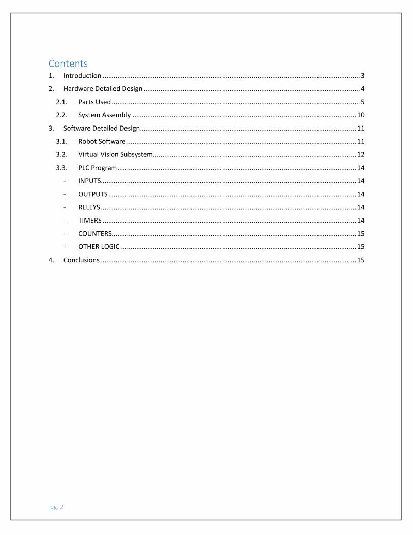
1. Introduction The current project aims to apply the knowledge acquired during the ISE 716 class, Automated System Engineering, on industrial automation, robotics and programming for automation. The goal of the project is to design, build (both hardware and software) and demonstrate an automated sorting system able to transport, sort and relocate parts having different shapes (round and square). As shown in Figure 1, the system mainly consists of (1) pneumatic actuator that pushes the unsorted parts on the conveyor belt; (2) conveyor belt that transports the unsorted parts; (3) two-arms robot (Baxter) that, with the help of a machine vision subsystem, sorts the cylinders from the cuboids. Other minor components of the system, needed to achieve a full automation, are (4) five proximity sensors used to detect the position of the parts during the operations; (5) DC motor that drives the conveyor belt; (6) start and stop push-buttons. A detailed description of the aforementioned components follows in Section 2.
Figure 1 System Design
The core steps of the automated sorting system are described in the following list, organized in chronological order:
1) The sorting system is started by a start push-button (Start) while an emergency button (E_Stop) can be used to stop the operations at each time in case of an emergency.
2) A random shape part (cylinder or cuboid) is manually placed in position 1 and detected by the proximity sensor 1 (ProxAtPneumatic);
3) ProxAtPneumatic trigs the extension mechanism of the pneumatic actuator that, helped by fixed guide rails, pushes the part on the conveyor belt in position 2 where it is detected by the proximity sensor 2 (ProxAtStart);
4) ProxAtStart triggers the DC motor to proceed forward and brings the part to position 3 where it is detected by the proximity sensor 3 (ProxAtEnd). Each time the part is either in position 1 or position 3, the DC motor stops to allow the placing and picking operations to and from the conveyor belt;
pg. 3
5) ProxAtEnd trigs the two-arms robot. The robot is equipped with a vision system able to distinguish the shape of the parts. Details of the robotic and virtual vision system are contained in Section 3;
6) Once the virtual vision system sorts the part’s shape, one of the two arms is activated. The robot arms are equipped with electrical parallel grippers that pick parts and place them in the proper container.
2. Hardware Detailed Design The following section describes the components used in the physical implementation of the robot assisted product sorting system. The systemic components and their functions are listed below.
PART NAME DESCRIPTION
PLC – Allen Bradley CompactLogixL23E-QBFC1B System Controller
24V/ 7.5A Power-Supply System Power Supply
Double Acting Cylinder Pneumatic Actuator
5/2 Solenoid Valve Air Supply for 2 position pneumatic actuator
NPN type Capacitive Proximity Sensors (x5) Operating Environment Sensors
Conveyor Belt Part transfer mechanism
Geared DC Motor Controller governed conveyor belt motion
24V high wattage relay
Machine Vision Assisted Industrial Robot(Baxter) Part Sorting Robot
Schneider XBTGT2330 HMI Human Machine Interface
pg. 4
2.1. Parts Used • PLC- Allen Bradley
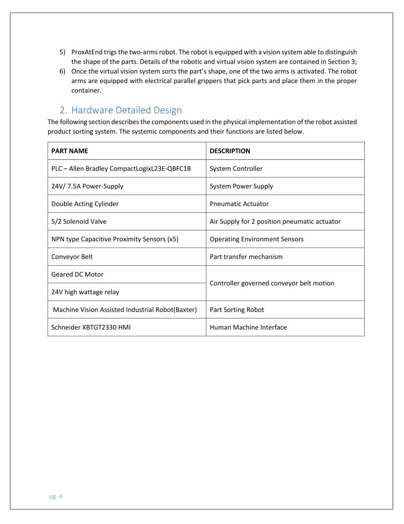
Figure 2: Allen Bradley PLC with 24V/7.5A power supply
The Allen Bradley programmable logic controller (PLC) is the system controller used to govern the automated functioning of the system.
The controller consists 32 I/O points which is able to take in 15 digital inputs and furnish 24 digital outputs with a square peak voltage of 24V.
The ladder logic governing the system is encoded in RS Logix5000 and runs on the PLC scanning through the program with 1 µs scan cycle, the logic addresses I/O ports which are part of the system’s inputs and outputs.
• Pneumatic Actuator – (Double Acting Cylinder)
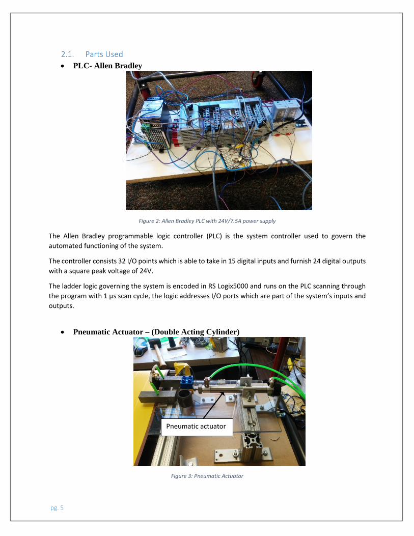
Figure 3: Pneumatic Actuator
Pneumatic actuator
pg. 5
Double-acting cylinders use compressed air to extend or retract the actuator piston.
They have two ports to allow air in, one for out-stroke and one for in-stroke. Stroke length for this design is not limited, however, increasing the stroke length, the piston rod is more vulnerable to buckling and bending.
Within the system layout, the double acting cylinder is the actuator used to push a part onto the conveyor belt, based on the sensory feedback from the proximity sensors.
• 5/2 Solenoid Valve
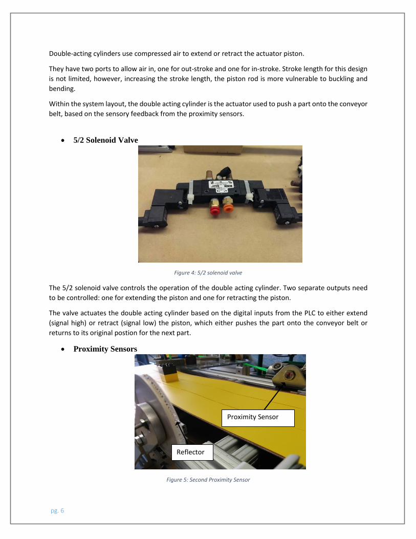
Figure 4: 5/2 solenoid valve
The 5/2 solenoid valve controls the operation of the double acting cylinder. Two separate outputs need to be controlled: one for extending the piston and one for retracting the piston.
The valve actuates the double acting cylinder based on the digital inputs from the PLC to either extend (signal high) or retract (signal low) the piston, which either pushes the part onto the conveyor belt or returns to its original postion for the next part.
• Proximity Sensors
Figure 5: Second Proximity Sensor
Proximity Sensor
Reflector
pg. 6
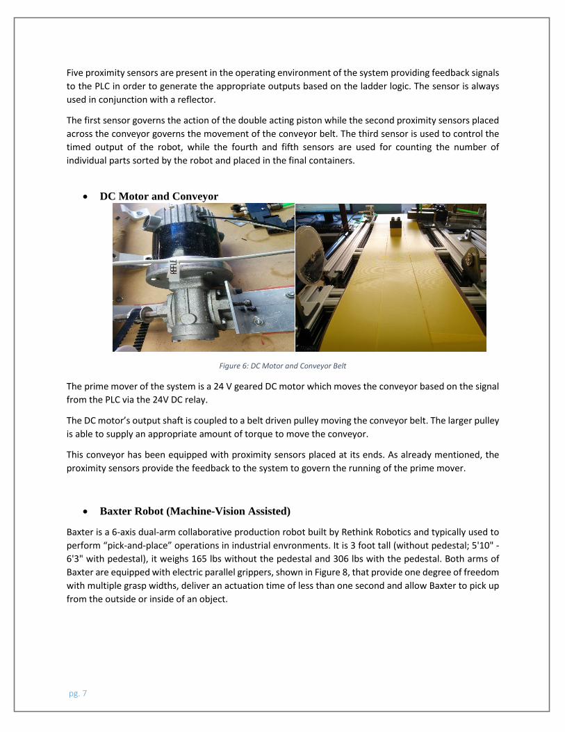
Five proximity sensors are present in the operating environment of the system providing feedback signals to the PLC in order to generate the appropriate outputs based on the ladder logic. The sensor is always used in conjunction with a reflector.
The first sensor governs the action of the double acting piston while the second proximity sensors placed across the conveyor governs the movement of the conveyor belt. The third sensor is used to control the timed output of the robot, while the fourth and fifth sensors are used for counting the number of individual parts sorted by the robot and placed in the final containers.
• DC Motor and Conveyor
Figure 6: DC Motor and Conveyor Belt
The prime mover of the system is a 24 V geared DC motor which moves the conveyor based on the signal from the PLC via the 24V DC relay.
The DC motor’s output shaft is coupled to a belt driven pulley moving the conveyor belt. The larger pulley is able to supply an appropriate amount of torque to move the conveyor.
This conveyor has been equipped with proximity sensors placed at its ends. As already mentioned, the proximity sensors provide the feedback to the system to govern the running of the prime mover.
• Baxter Robot (Machine-Vision Assisted)
Baxter is a 6-axis dual-arm collaborative production robot built by Rethink Robotics and typically used to perform “pick-and-place” operations in industrial envronments. It is 3 foot tall (without pedestal; 5'10" - 6'3" with pedestal), it weighs 165 lbs without the pedestal and 306 lbs with the pedestal. Both arms of Baxter are equipped with electric parallel grippers, shown in Figure 8, that provide one degree of freedom with multiple grasp widths, deliver an actuation time of less than one second and allow Baxter to pick up from the outside or inside of an object.
pg. 7
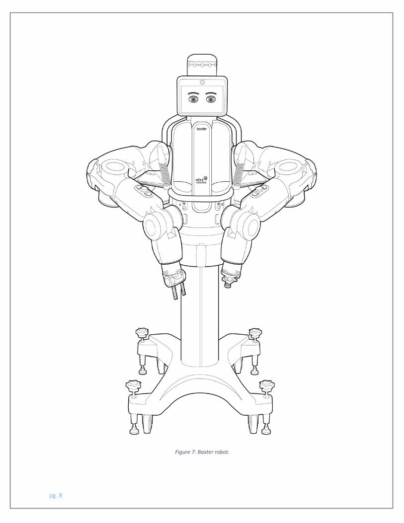
Figure 7: Baxter robot.
pg. 8
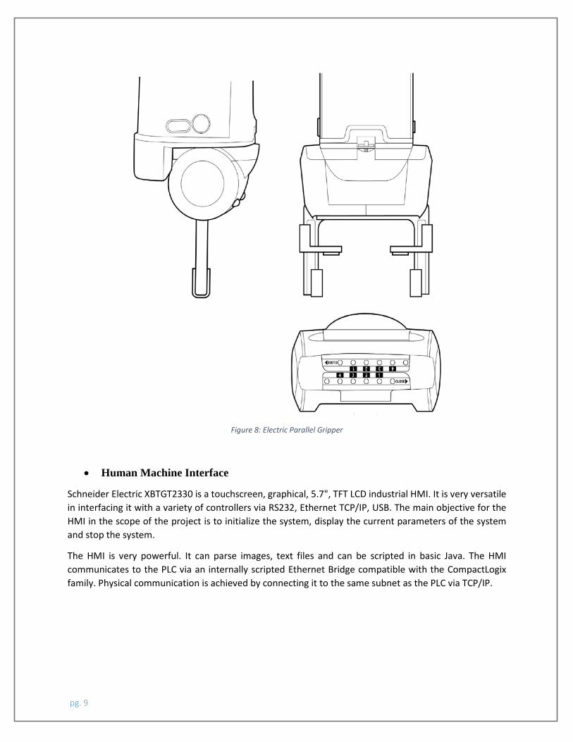
Figure 8: Electric Parallel Gripper
• Human Machine Interface
Schneider Electric XBTGT2330 is a touchscreen, graphical, 5.7", TFT LCD industrial HMI. It is very versatile in interfacing it with a variety of controllers via RS232, Ethernet TCP/IP, USB. The main objective for the HMI in the scope of the project is to initialize the system, display the current parameters of the system and stop the system.
The HMI is very powerful. It can parse images, text files and can be scripted in basic Java. The HMI communicates to the PLC via an internally scripted Ethernet Bridge compatible with the CompactLogix family. Physical communication is achieved by connecting it to the same subnet as the PLC via TCP/IP.
pg. 9
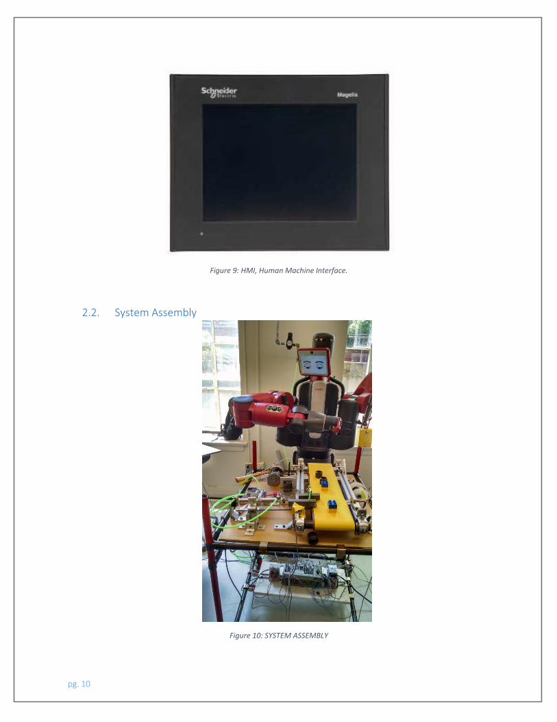
Figure 9: HMI, Human Machine Interface.
2.2. System Assembly
Figure 10: SYSTEM ASSEMBLY
pg. 10
The picture above shows the complete assembly of the physical system which has been fabricated for this project. The raw stock used for the conveyor support structure is 80/20 T-slotted aluminum 6105-T5. The glass plate allows on which the double acting cylinder is mounted using L-slots provides a surface with the appropriate sliding friction to allow the incoming part to be transported from the initial discrete position (sensor 2) to its second discrete state (sensor 3). The L-slots are fixed in position using standard sized screws and hexagonal nuts.
3. Software Detailed Design The automated sorting system contains three main subsystems each requiring a different software to operate: (1) the robot executes the operations programmed through the software interface Intera; (2) the sorting system is based on a virtual vision subsystem embedded in the robotic system; (3) finally the whole assembly is governed by a PLC, Allen Bradley CompacLogic, programmed in ladder logic via RSLogix5000.
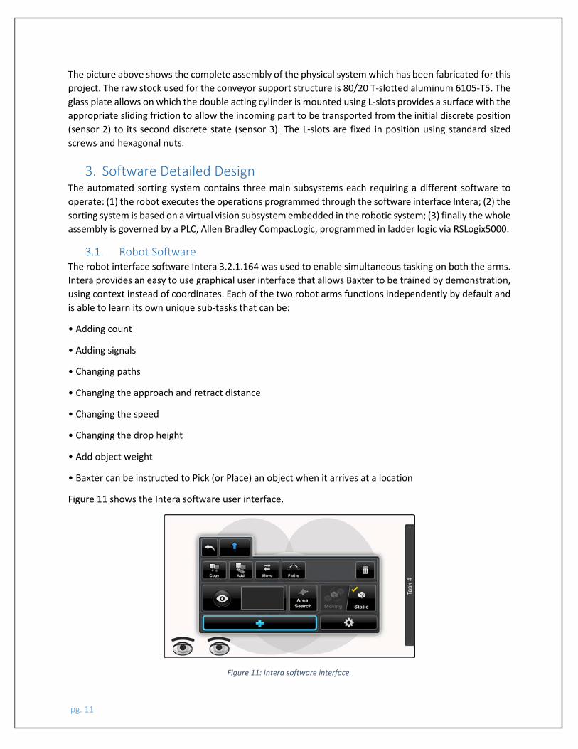
3.1. Robot Software The robot interface software Intera 3.2.1.164 was used to enable simultaneous tasking on both the arms. Intera provides an easy to use graphical user interface that allows Baxter to be trained by demonstration, using context instead of coordinates. Each of the two robot arms functions independently by default and is able to learn its own unique sub-tasks that can be:
• Adding count
• Adding signals
• Changing paths
• Changing the approach and retract distance
• Changing the speed
• Changing the drop height
• Add object weight
• Baxter can be instructed to Pick (or Place) an object when it arrives at a location
Figure 11 shows the Intera software user interface.
Figure 11: Intera software interface.
pg. 11
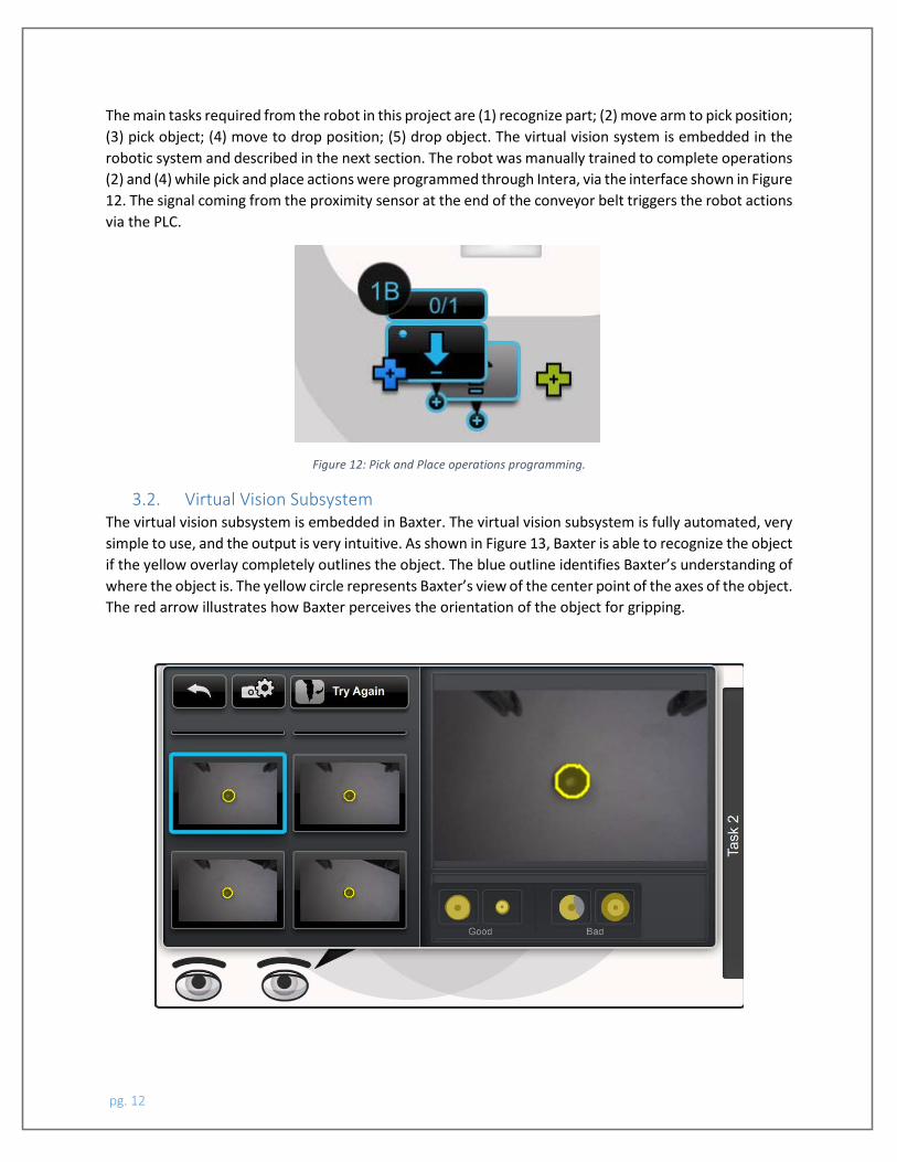
The main tasks required from the robot in this project are (1) recognize part; (2) move arm to pick position; (3) pick object; (4) move to drop position; (5) drop object. The virtual vision system is embedded in the robotic system and described in the next section. The robot was manually trained to complete operations (2) and (4) while pick and place actions were programmed through Intera, via the interface shown in Figure 12. The signal coming from the proximity sensor at the end of the conveyor belt triggers the robot actions via the PLC.
Figure 12: Pick and Place operations programming.
3.2. Virtual Vision Subsystem The virtual vision subsystem is embedded in Baxter. The virtual vision subsystem is fully automated, very simple to use, and the output is very intuitive. As shown in Figure 13, Baxter is able to recognize the object if the yellow overlay completely outlines the object. The blue outline identifies Baxter’s understanding of where the object is. The yellow circle represents Baxter’s view of the center point of the axes of the object. The red arrow illustrates how Baxter perceives the orientation of the object for gripping.
pg. 12
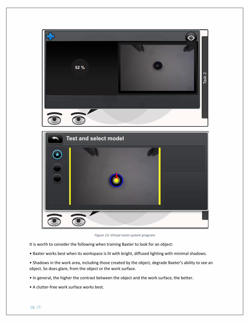
Figure 13: Virtual vision system program.
It is worth to consider the following when training Baxter to look for an object:
• Baxter works best when its workspace is lit with bright, diffused lighting with minimal shadows.
• Shadows in the work area, including those created by the object, degrade Baxter’s ability to see an object. So does glare, from the object or the work surface.
• In general, the higher the contrast between the object and the work surface, the better.
• A clutter-free work surface works best.
pg. 13
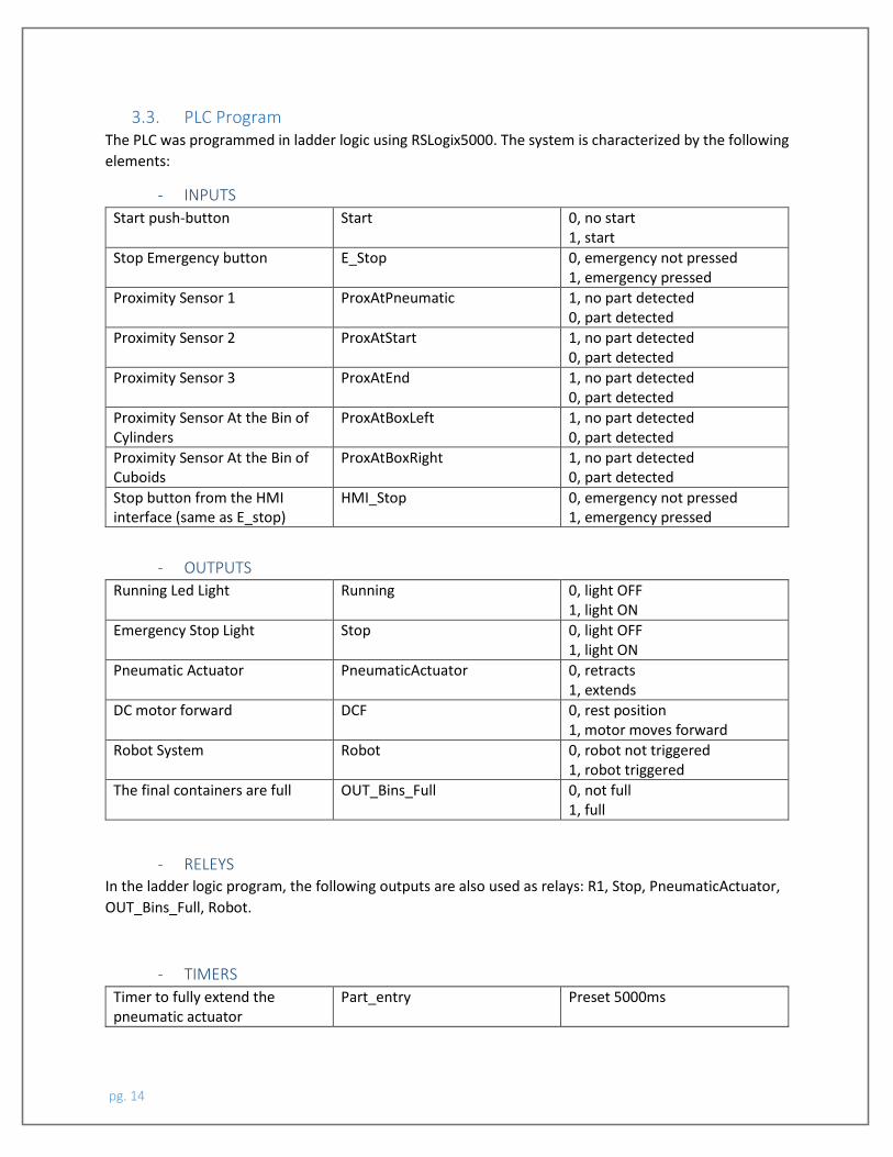
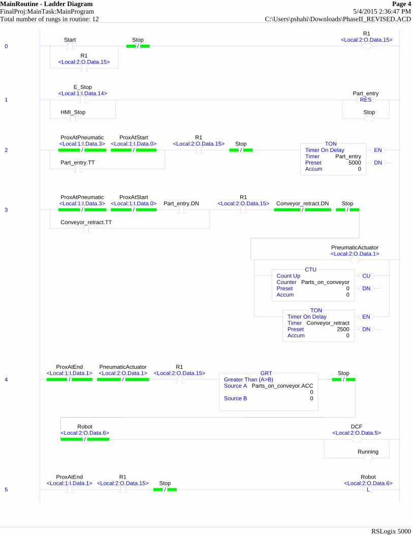
3.3. PLC Program The PLC was programmed in ladder logic using RSLogix5000. The system is characterized by the following elements:
- INPUTS Start push-button Start 0, no start
1, start Stop Emergency button E_Stop 0, emergency not pressed
1, emergency pressed Proximity Sensor 1 ProxAtPneumatic 1, no part detected
0, part detected Proximity Sensor 2 ProxAtStart 1, no part detected
0, part detected Proximity Sensor 3 ProxAtEnd 1, no part detected
0, part detected Proximity Sensor At the Bin of Cylinders
ProxAtBoxLeft 1, no part detected 0, part detected
Proximity Sensor At the Bin of Cuboids
ProxAtBoxRight 1, no part detected 0, part detected
Stop button from the HMI interface (same as E_stop)
HMI_Stop 0, emergency not pressed 1, emergency pressed
- OUTPUTS
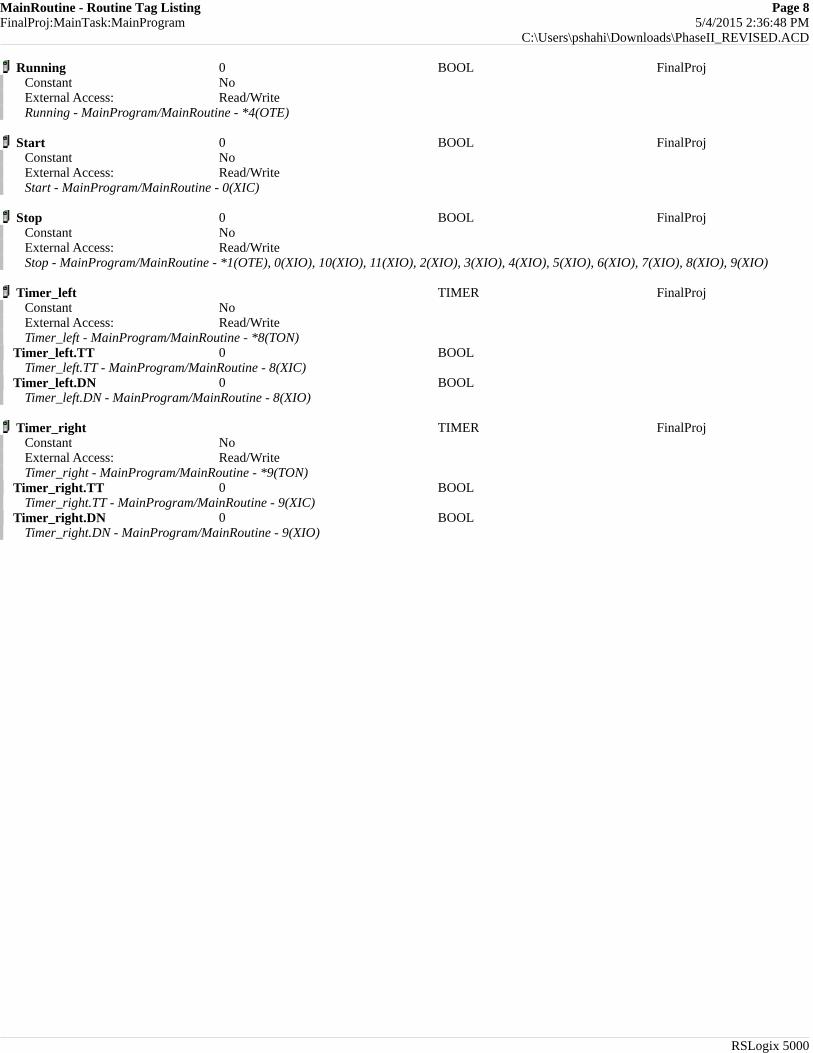
Running Led Light Running 0, light OFF 1, light ON
Emergency Stop Light Stop 0, light OFF 1, light ON
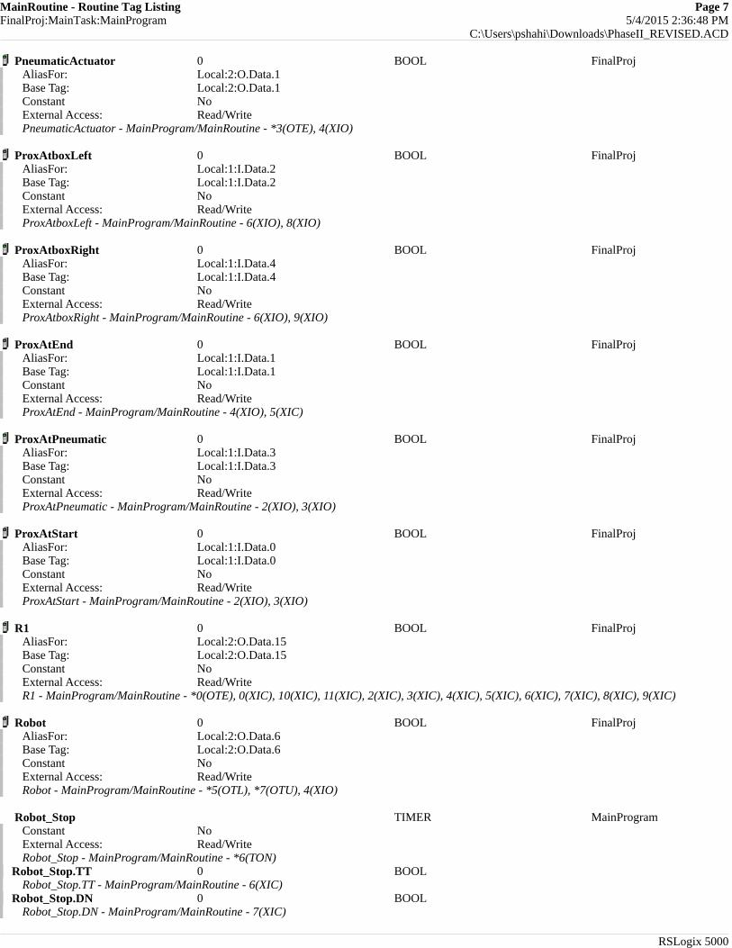
Pneumatic Actuator PneumaticActuator 0, retracts 1, extends
DC motor forward DCF 0, rest position 1, motor moves forward
Robot System Robot 0, robot not triggered 1, robot triggered
The final containers are full OUT_Bins_Full 0, not full 1, full
- RELEYS In the ladder logic program, the following outputs are also used as relays: R1, Stop, PneumaticActuator, OUT_Bins_Full, Robot.
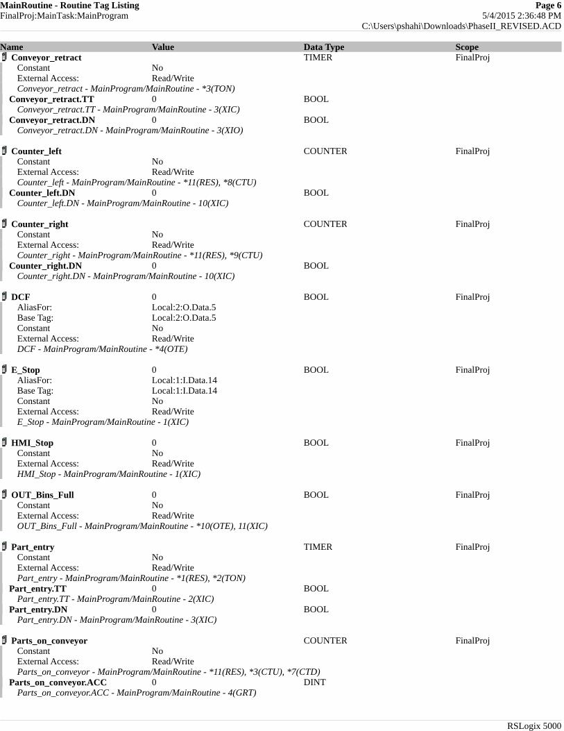
- TIMERS Timer to fully extend the pneumatic actuator
Part_entry Preset 5000ms
pg. 14
Timer to fully retract the pneumatic actuator
Conveyor_retract Preset 2500ms
Timer required to stop the robot
Robot_Stop Preset 1000ms
Timer to place cylinders in left bin
Timer_left Preset 6000ms
Timer to place cuboids in right bin
Timer_right Preset 6000ms
- COUNTERS
Counter to count the number of parts present on the conveyor belt (counter UP and counter DOWN)
Parts_on_conveyor Preset 0
Counter to count the number of parts present in the cuboids bin (counter UP)
Counter_right Preset 4
Counter to count the number of parts present in the cylinders bin (counter UP)
Counter_left Preset 4
- OTHER LOGIC “Greater Than” is used to control the DC motor: when there are no parts on the conveyor belt (Parts_on_conveyor = 0) the motor doesn’t run
GRT Parts_on_conveyor > 0
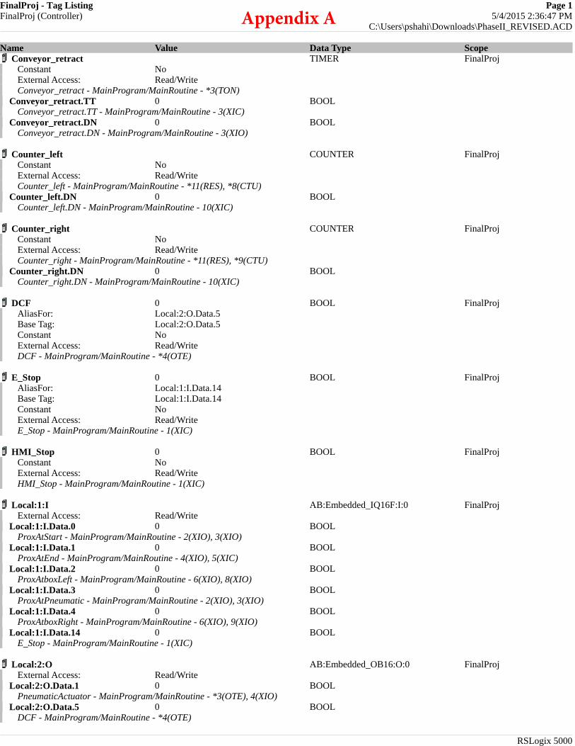
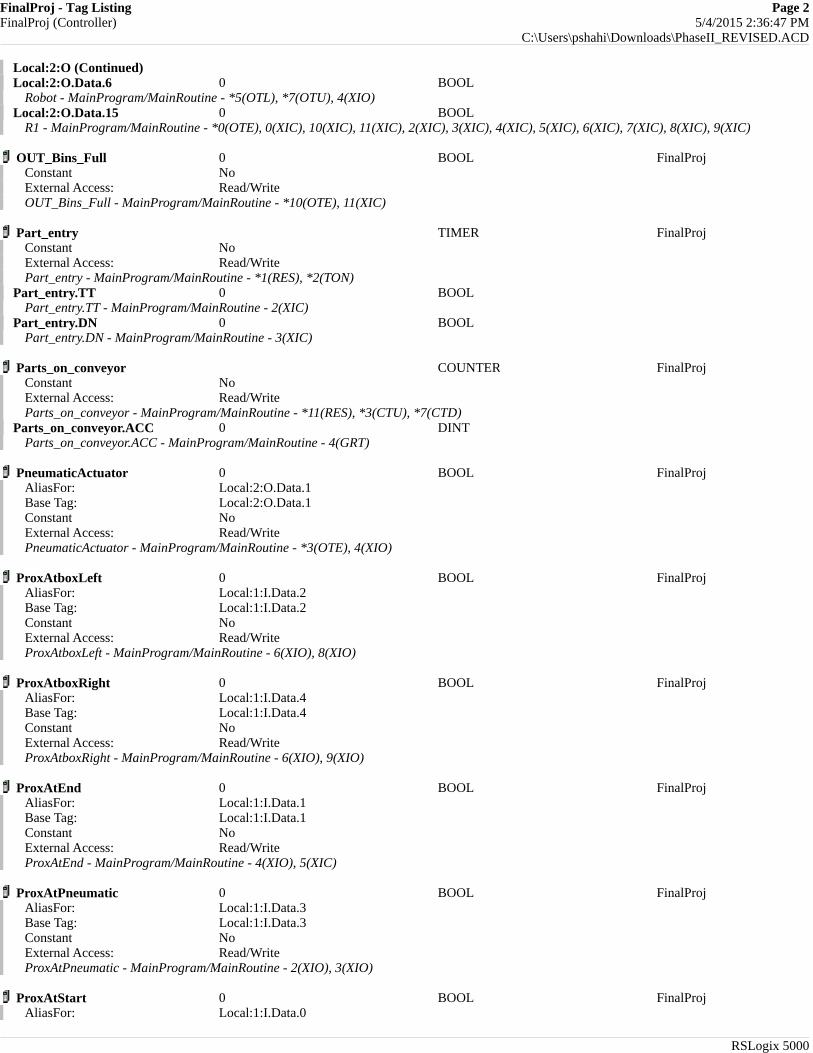
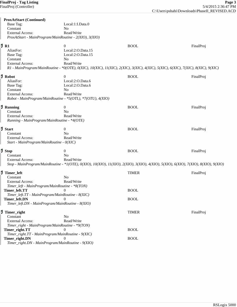
Appendix A contains the ladder logic diagram that was programmed using the RSLogix 5000 software.
4. Conclusions The automated sorting system was successfully designed, built and demonstrated at the NCSU ISE automation Lab. The system successfully transports, sorts and organizes parts having different shape (cylinders and cubes).
Room is left for improvements. For instance, (1) instead of being able to sort only two different shapes, the system can be redesigned to sort more different shapes and relocate them. In order to realize this, it is necessary to build a better interface between the robot controller and the PLC in order to have multiple inputs going to the robot controller from the PLC. This was not possible in this project with the available hardware. (2) If another robot would be available, it could be used upstream instead of the pneumatic actuator to have a more precise, fast and reliable placing mechanism of the parts on the conveyor belt. (3) Instead of sorting parts having totally different shapes (cubes from cylinders) the system could be used
pg. 15
in a more attractive industrial application to locate defective parts in a production line that have the same overall shape but slightly different geometries/defects.
The sorting system designed during the final project of ISE716, finds wide applications in the most common industrial environments. A very useful application of such a system can be that of sorting and excluding defective parts in an automated production line or that of organizing random parts arriving on belts in a factory warehouse.
pg. 16
FinalProj - Tag Listing Page 1FinalProj (Controller) 5/4/2015 2:36:47 PM
C:\Users\pshahi\Downloads\PhaseII_REVISED.ACD
RSLogix 5000
Name Value Data Type ScopeConveyor_retract TIMER FinalProj
Constant NoExternal Access: Read/WriteConveyor_retract - MainProgram/MainRoutine - *3(TON)
Conveyor_retract.TT 0 BOOLConveyor_retract.TT - MainProgram/MainRoutine - 3(XIC)
Conveyor_retract.DN 0 BOOLConveyor_retract.DN - MainProgram/MainRoutine - 3(XIO)
Counter_left COUNTER FinalProjConstant NoExternal Access: Read/WriteCounter_left - MainProgram/MainRoutine - *11(RES), *8(CTU)
Counter_left.DN 0 BOOLCounter_left.DN - MainProgram/MainRoutine - 10(XIC)
Counter_right COUNTER FinalProjConstant NoExternal Access: Read/WriteCounter_right - MainProgram/MainRoutine - *11(RES), *9(CTU)
Counter_right.DN 0 BOOLCounter_right.DN - MainProgram/MainRoutine - 10(XIC)
DCF 0 BOOL FinalProjAliasFor: Local:2:O.Data.5Base Tag: Local:2:O.Data.5Constant NoExternal Access: Read/WriteDCF - MainProgram/MainRoutine - *4(OTE)
E_Stop 0 BOOL FinalProjAliasFor: Local:1:I.Data.14Base Tag: Local:1:I.Data.14Constant NoExternal Access: Read/WriteE_Stop - MainProgram/MainRoutine - 1(XIC)
HMI_Stop 0 BOOL FinalProjConstant NoExternal Access: Read/WriteHMI_Stop - MainProgram/MainRoutine - 1(XIC)
Local:1:I AB:Embedded_IQ16F:I:0 FinalProjExternal Access: Read/Write
Local:1:I.Data.0 0 BOOLProxAtStart - MainProgram/MainRoutine - 2(XIO), 3(XIO)
Local:1:I.Data.1 0 BOOLProxAtEnd - MainProgram/MainRoutine - 4(XIO), 5(XIC)
Local:1:I.Data.2 0 BOOLProxAtboxLeft - MainProgram/MainRoutine - 6(XIO), 8(XIO)
Local:1:I.Data.3 0 BOOLProxAtPneumatic - MainProgram/MainRoutine - 2(XIO), 3(XIO)
Local:1:I.Data.4 0 BOOLProxAtboxRight - MainProgram/MainRoutine - 6(XIO), 9(XIO)
Local:1:I.Data.14 0 BOOLE_Stop - MainProgram/MainRoutine - 1(XIC)
Local:2:O AB:Embedded_OB16:O:0 FinalProjExternal Access: Read/Write
Local:2:O.Data.1 0 BOOLPneumaticActuator - MainProgram/MainRoutine - *3(OTE), 4(XIO)
Local:2:O.Data.5 0 BOOLDCF - MainProgram/MainRoutine - *4(OTE)
Appendix A
FinalProj - Tag Listing Page 2FinalProj (Controller) 5/4/2015 2:36:47 PM
C:\Users\pshahi\Downloads\PhaseII_REVISED.ACD
RSLogix 5000
Local:2:O (Continued)Local:2:O.Data.6 0 BOOL
Robot - MainProgram/MainRoutine - *5(OTL), *7(OTU), 4(XIO)Local:2:O.Data.15 0 BOOL
R1 - MainProgram/MainRoutine - *0(OTE), 0(XIC), 10(XIC), 11(XIC), 2(XIC), 3(XIC), 4(XIC), 5(XIC), 6(XIC), 7(XIC), 8(XIC), 9(XIC)
OUT_Bins_Full 0 BOOL FinalProjConstant NoExternal Access: Read/WriteOUT_Bins_Full - MainProgram/MainRoutine - *10(OTE), 11(XIC)
Part_entry TIMER FinalProjConstant NoExternal Access: Read/WritePart_entry - MainProgram/MainRoutine - *1(RES), *2(TON)
Part_entry.TT 0 BOOLPart_entry.TT - MainProgram/MainRoutine - 2(XIC)
Part_entry.DN 0 BOOLPart_entry.DN - MainProgram/MainRoutine - 3(XIC)
Parts_on_conveyor COUNTER FinalProjConstant NoExternal Access: Read/WriteParts_on_conveyor - MainProgram/MainRoutine - *11(RES), *3(CTU), *7(CTD)
Parts_on_conveyor.ACC 0 DINTParts_on_conveyor.ACC - MainProgram/MainRoutine - 4(GRT)
PneumaticActuator 0 BOOL FinalProjAliasFor: Local:2:O.Data.1Base Tag: Local:2:O.Data.1Constant NoExternal Access: Read/WritePneumaticActuator - MainProgram/MainRoutine - *3(OTE), 4(XIO)
ProxAtboxLeft 0 BOOL FinalProjAliasFor: Local:1:I.Data.2Base Tag: Local:1:I.Data.2Constant NoExternal Access: Read/WriteProxAtboxLeft - MainProgram/MainRoutine - 6(XIO), 8(XIO)
ProxAtboxRight 0 BOOL FinalProjAliasFor: Local:1:I.Data.4Base Tag: Local:1:I.Data.4Constant NoExternal Access: Read/WriteProxAtboxRight - MainProgram/MainRoutine - 6(XIO), 9(XIO)
ProxAtEnd 0 BOOL FinalProjAliasFor: Local:1:I.Data.1Base Tag: Local:1:I.Data.1Constant NoExternal Access: Read/WriteProxAtEnd - MainProgram/MainRoutine - 4(XIO), 5(XIC)
ProxAtPneumatic 0 BOOL FinalProjAliasFor: Local:1:I.Data.3Base Tag: Local:1:I.Data.3Constant NoExternal Access: Read/WriteProxAtPneumatic - MainProgram/MainRoutine - 2(XIO), 3(XIO)
ProxAtStart 0 BOOL FinalProjAliasFor: Local:1:I.Data.0
FinalProj - Tag Listing Page 3FinalProj (Controller) 5/4/2015 2:36:47 PM
C:\Users\pshahi\Downloads\PhaseII_REVISED.ACD
RSLogix 5000
ProxAtStart (Continued)Base Tag: Local:1:I.Data.0Constant NoExternal Access: Read/WriteProxAtStart - MainProgram/MainRoutine - 2(XIO), 3(XIO)
R1 0 BOOL FinalProjAliasFor: Local:2:O.Data.15Base Tag: Local:2:O.Data.15Constant NoExternal Access: Read/WriteR1 - MainProgram/MainRoutine - *0(OTE), 0(XIC), 10(XIC), 11(XIC), 2(XIC), 3(XIC), 4(XIC), 5(XIC), 6(XIC), 7(XIC), 8(XIC), 9(XIC)
Robot 0 BOOL FinalProjAliasFor: Local:2:O.Data.6Base Tag: Local:2:O.Data.6Constant NoExternal Access: Read/WriteRobot - MainProgram/MainRoutine - *5(OTL), *7(OTU), 4(XIO)
Running 0 BOOL FinalProjConstant NoExternal Access: Read/WriteRunning - MainProgram/MainRoutine - *4(OTE)
Start 0 BOOL FinalProjConstant NoExternal Access: Read/WriteStart - MainProgram/MainRoutine - 0(XIC)
Stop 0 BOOL FinalProjConstant NoExternal Access: Read/WriteStop - MainProgram/MainRoutine - *1(OTE), 0(XIO), 10(XIO), 11(XIO), 2(XIO), 3(XIO), 4(XIO), 5(XIO), 6(XIO), 7(XIO), 8(XIO), 9(XIO)
Timer_left TIMER FinalProjConstant NoExternal Access: Read/WriteTimer_left - MainProgram/MainRoutine - *8(TON)
Timer_left.TT 0 BOOLTimer_left.TT - MainProgram/MainRoutine - 8(XIC)
Timer_left.DN 0 BOOLTimer_left.DN - MainProgram/MainRoutine - 8(XIO)
Timer_right TIMER FinalProjConstant NoExternal Access: Read/WriteTimer_right - MainProgram/MainRoutine - *9(TON)
Timer_right.TT 0 BOOLTimer_right.TT - MainProgram/MainRoutine - 9(XIC)
Timer_right.DN 0 BOOLTimer_right.DN - MainProgram/MainRoutine - 9(XIO)
MainRoutine - Ladder Diagram Page 4FinalProj:MainTask:MainProgram 5/4/2015 2:36:47 PMTotal number of rungs in routine: 12 C:\Users\pshahi\Downloads\PhaseII_REVISED.ACD
RSLogix 5000
0Start
R1<Local:2:O.Data.15>
/Stop
R1<Local:2:O.Data.15>
1
E_Stop<Local:1:I.Data.14>
HMI_Stop
RESPart_entry
Stop
2 /
ProxAtPneumatic<Local:1:I.Data.3>
/
ProxAtStart<Local:1:I.Data.0>
Part_entry.TT
R1<Local:2:O.Data.15>
/Stop
EN
DN
Timer On DelayTimer Part_entryPreset 5000Accum 0
TON
3 /
ProxAtPneumatic<Local:1:I.Data.3>
/
ProxAtStart<Local:1:I.Data.0> Part_entry.DN
Conveyor_retract.TT
R1<Local:2:O.Data.15>
/Conveyor_retract.DN
/Stop
PneumaticActuator<Local:2:O.Data.1>
CU
DN
Count UpCounter Parts_on_conveyorPreset 0Accum 0
CTU
EN
DN
Timer On DelayTimer Conveyor_retractPreset 2500Accum 0
TON
4 /
ProxAtEnd<Local:1:I.Data.1>
/
PneumaticActuator<Local:2:O.Data.1>
R1<Local:2:O.Data.15>
Greater Than (A>B)Source A Parts_on_conveyor.ACC 0Source B 0
GRT/
Stop
/
Robot<Local:2:O.Data.6>
DCF<Local:2:O.Data.5>
Running
5
ProxAtEnd<Local:1:I.Data.1>
R1<Local:2:O.Data.15>
/Stop
L
Robot<Local:2:O.Data.6>

MainRoutine - Ladder Diagram Page 5FinalProj:MainTask:MainProgram 5/4/2015 2:36:48 PMTotal number of rungs in routine: 12 C:\Users\pshahi\Downloads\PhaseII_REVISED.ACD
RSLogix 5000
6 /
ProxAtboxLeft<Local:1:I.Data.2>
/
ProxAtboxRight<Local:1:I.Data.4>
Robot_Stop.TT
R1<Local:2:O.Data.15>
/Stop
EN
DN
Timer On DelayTimer Robot_StopPreset 1000Accum 0
TON
7Robot_Stop.DN
R1<Local:2:O.Data.15>
/Stop
U
Robot<Local:2:O.Data.6>
CD
DN
Count DownCounter Parts_on_conveyorPreset 0Accum 0
CTD
8 /
ProxAtboxLeft<Local:1:I.Data.2>
Timer_left.TT
R1<Local:2:O.Data.15>
/Stop
/Timer_left.DN
CU
DN
Count UpCounter Counter_leftPreset 4Accum 0
CTU
EN
DN
Timer On DelayTimer Timer_leftPreset 6000Accum 0
TON
9 /
ProxAtboxRight<Local:1:I.Data.4>
Timer_right.TT
R1<Local:2:O.Data.15>
/Stop
/Timer_right.DN
CU
DN
Count UpCounter Counter_rightPreset 4Accum 0
CTU
EN
DN
Timer On DelayTimer Timer_rightPreset 6000Accum 0
TON
10Counter_left.DN Counter_right.DN
R1<Local:2:O.Data.15>
/Stop OUT_Bins_Full
11OUT_Bins_Full
R1<Local:2:O.Data.15>
/Stop
RESParts_on_conveyor
RESCounter_left
RESCounter_right
(End)
MainRoutine - Routine Tag Listing Page 6FinalProj:MainTask:MainProgram 5/4/2015 2:36:48 PM
C:\Users\pshahi\Downloads\PhaseII_REVISED.ACD
RSLogix 5000
Name Value Data Type ScopeConveyor_retract TIMER FinalProj
Constant NoExternal Access: Read/WriteConveyor_retract - MainProgram/MainRoutine - *3(TON)
Conveyor_retract.TT 0 BOOLConveyor_retract.TT - MainProgram/MainRoutine - 3(XIC)
Conveyor_retract.DN 0 BOOLConveyor_retract.DN - MainProgram/MainRoutine - 3(XIO)
Counter_left COUNTER FinalProjConstant NoExternal Access: Read/WriteCounter_left - MainProgram/MainRoutine - *11(RES), *8(CTU)
Counter_left.DN 0 BOOLCounter_left.DN - MainProgram/MainRoutine - 10(XIC)
Counter_right COUNTER FinalProjConstant NoExternal Access: Read/WriteCounter_right - MainProgram/MainRoutine - *11(RES), *9(CTU)
Counter_right.DN 0 BOOLCounter_right.DN - MainProgram/MainRoutine - 10(XIC)
DCF 0 BOOL FinalProjAliasFor: Local:2:O.Data.5Base Tag: Local:2:O.Data.5Constant NoExternal Access: Read/WriteDCF - MainProgram/MainRoutine - *4(OTE)
E_Stop 0 BOOL FinalProjAliasFor: Local:1:I.Data.14Base Tag: Local:1:I.Data.14Constant NoExternal Access: Read/WriteE_Stop - MainProgram/MainRoutine - 1(XIC)
HMI_Stop 0 BOOL FinalProjConstant NoExternal Access: Read/WriteHMI_Stop - MainProgram/MainRoutine - 1(XIC)
OUT_Bins_Full 0 BOOL FinalProjConstant NoExternal Access: Read/WriteOUT_Bins_Full - MainProgram/MainRoutine - *10(OTE), 11(XIC)
Part_entry TIMER FinalProjConstant NoExternal Access: Read/WritePart_entry - MainProgram/MainRoutine - *1(RES), *2(TON)
Part_entry.TT 0 BOOLPart_entry.TT - MainProgram/MainRoutine - 2(XIC)
Part_entry.DN 0 BOOLPart_entry.DN - MainProgram/MainRoutine - 3(XIC)
Parts_on_conveyor COUNTER FinalProjConstant NoExternal Access: Read/WriteParts_on_conveyor - MainProgram/MainRoutine - *11(RES), *3(CTU), *7(CTD)
Parts_on_conveyor.ACC 0 DINTParts_on_conveyor.ACC - MainProgram/MainRoutine - 4(GRT)
MainRoutine - Routine Tag Listing Page 7FinalProj:MainTask:MainProgram 5/4/2015 2:36:48 PM
C:\Users\pshahi\Downloads\PhaseII_REVISED.ACD
RSLogix 5000
PneumaticActuator 0 BOOL FinalProjAliasFor: Local:2:O.Data.1Base Tag: Local:2:O.Data.1Constant NoExternal Access: Read/WritePneumaticActuator - MainProgram/MainRoutine - *3(OTE), 4(XIO)
ProxAtboxLeft 0 BOOL FinalProjAliasFor: Local:1:I.Data.2Base Tag: Local:1:I.Data.2Constant NoExternal Access: Read/WriteProxAtboxLeft - MainProgram/MainRoutine - 6(XIO), 8(XIO)
ProxAtboxRight 0 BOOL FinalProjAliasFor: Local:1:I.Data.4Base Tag: Local:1:I.Data.4Constant NoExternal Access: Read/WriteProxAtboxRight - MainProgram/MainRoutine - 6(XIO), 9(XIO)
ProxAtEnd 0 BOOL FinalProjAliasFor: Local:1:I.Data.1Base Tag: Local:1:I.Data.1Constant NoExternal Access: Read/WriteProxAtEnd - MainProgram/MainRoutine - 4(XIO), 5(XIC)
ProxAtPneumatic 0 BOOL FinalProjAliasFor: Local:1:I.Data.3Base Tag: Local:1:I.Data.3Constant NoExternal Access: Read/WriteProxAtPneumatic - MainProgram/MainRoutine - 2(XIO), 3(XIO)
ProxAtStart 0 BOOL FinalProjAliasFor: Local:1:I.Data.0Base Tag: Local:1:I.Data.0Constant NoExternal Access: Read/WriteProxAtStart - MainProgram/MainRoutine - 2(XIO), 3(XIO)
R1 0 BOOL FinalProjAliasFor: Local:2:O.Data.15Base Tag: Local:2:O.Data.15Constant NoExternal Access: Read/WriteR1 - MainProgram/MainRoutine - *0(OTE), 0(XIC), 10(XIC), 11(XIC), 2(XIC), 3(XIC), 4(XIC), 5(XIC), 6(XIC), 7(XIC), 8(XIC), 9(XIC)
Robot 0 BOOL FinalProjAliasFor: Local:2:O.Data.6Base Tag: Local:2:O.Data.6Constant NoExternal Access: Read/WriteRobot - MainProgram/MainRoutine - *5(OTL), *7(OTU), 4(XIO)
Robot_Stop TIMER MainProgramConstant NoExternal Access: Read/WriteRobot_Stop - MainProgram/MainRoutine - *6(TON)
Robot_Stop.TT 0 BOOLRobot_Stop.TT - MainProgram/MainRoutine - 6(XIC)
Robot_Stop.DN 0 BOOLRobot_Stop.DN - MainProgram/MainRoutine - 7(XIC)
MainRoutine - Routine Tag Listing Page 8FinalProj:MainTask:MainProgram 5/4/2015 2:36:48 PM
C:\Users\pshahi\Downloads\PhaseII_REVISED.ACD
RSLogix 5000
Running 0 BOOL FinalProjConstant NoExternal Access: Read/WriteRunning - MainProgram/MainRoutine - *4(OTE)
Start 0 BOOL FinalProjConstant NoExternal Access: Read/WriteStart - MainProgram/MainRoutine - 0(XIC)
Stop 0 BOOL FinalProjConstant NoExternal Access: Read/WriteStop - MainProgram/MainRoutine - *1(OTE), 0(XIO), 10(XIO), 11(XIO), 2(XIO), 3(XIO), 4(XIO), 5(XIO), 6(XIO), 7(XIO), 8(XIO), 9(XIO)
Timer_left TIMER FinalProjConstant NoExternal Access: Read/WriteTimer_left - MainProgram/MainRoutine - *8(TON)
Timer_left.TT 0 BOOLTimer_left.TT - MainProgram/MainRoutine - 8(XIC)
Timer_left.DN 0 BOOLTimer_left.DN - MainProgram/MainRoutine - 8(XIO)
Timer_right TIMER FinalProjConstant NoExternal Access: Read/WriteTimer_right - MainProgram/MainRoutine - *9(TON)
Timer_right.TT 0 BOOLTimer_right.TT - MainProgram/MainRoutine - 9(XIC)
Timer_right.DN 0 BOOLTimer_right.DN - MainProgram/MainRoutine - 9(XIO)

![Index []...Autumn Semester classes resume Autumn Semester Make-up Classes Autumn Semester Final Exams schedule available on Loyola Autumn Semester classes end Autumn Semester Final](https://img.pdfslide.net/doc/110x75/5eccb0aaa0af283cb576e713/index-autumn-semester-classes-resume-autumn-semester-make-up-classes-autumn.jpg)


![fourth semester final[1]](https://img.pdfslide.net/doc/110x75/546586adb4af9f680b8b50fa/fourth-semester-final1.jpg)