Embed Size (px)
Citation preview

2018
ISIMET LP1
Science Lab Utility Safety Package Installation Manual

1
LP1 Rev: 101
ISIMET LP1 Installation Manual Copyright © 2018 ISIMET/MAPA, LLC. All rights reserved. Patent 6,757,589 B1, 6,990,393 B2, 8,543,225, Other Patents Pending This document is copyrighted. This document may not, in whole or part, be copied, duplicated, reproduced, translated, electronically stored, or reduced to machine readable form without prior written consent from ISIMET. Although the material contained herein has been carefully reviewed, ISIMET does not warrant it to be free of errors or omissions. ISIMET reserves the right to make corrections, updates, revisions, or changes to the information contained herein. ISIMET is a trademark of ISIMET/MAPA, LLC, an affiliate of WCM Industries, Inc.
Printed in the United States of America.

2
LP1 Rev: 101
Table of Contents ISIMET LP1 -Science Lab Utility Safety Package ........................................................................................ 3
Important Warnings ................................................................................................................................ 4
Parts List.................................................................................................................................................. 5
Utility Controller .............................................................................................................................. 5
Gas and Water Solenoid Panel ......................................................................................................... 5
Electrical Panel ................................................................................................................................ 5
Panic Button .................................................................................................................................... 5
Fuel Gas Sensor ............................................................................................................................... 5
Emergency Shower Monitor ............................................................................................................ 5
Emergency Monitoring Beacon ........................................................................................................ 5
Mounting the Utility Controller (UtC)....................................................................................................... 6
Mounting the E- and S-Series Enclosure ................................................................................................... 8
Mounting the Panic Button, Fuel Gas Sensor, Emergency Monitor Beacon, and Emergency Shower Monitor ................................................................................................................................................. 10
Electrical Conduit Installation ................................................................................................................ 11
UtC Control Panel .................................................................................................................................. 14
Control Panel Terminal Definitions ........................................................................................................ 15
Main Terminal ............................................................................................................................... 15
Control Wiring Terminal ................................................................................................................. 15
Fuel Gas Sensor ..................................................................................................................................... 22
Pressure Sensor (Transducer) ................................................................................................................ 23
Emergency Shower Monitor .................................................................................................................. 24
Monitoring Beacon ................................................................................................................................ 25
(Optional) External Fire Alarm ............................................................................................................... 26
(Optional) Building Energy Management System ................................................................................... 27
Connecting Power to the UtC ................................................................................................................ 28
(Optional) Installing UtC and S-Series Trim Plate .................................................................................... 29
Installing Covers .................................................................................................................................... 29
Installing UtC Door Panel ....................................................................................................................... 30
UtC Fuse Specifications.......................................................................................................................... 30
Acronyms and Common Terms .............................................................................................................. 31

3
LP1 Rev: 101
ISIMET LP1 -Science Lab Utility Safety Package
Providing ultimate authority and control over a laboratory utility system to authorized personnel. At any time, natural gas, water, and electrical can be de-activated by use of a Panic Button, Building Fire Alarm System, Building Energy Management System (EMS), and/or programmable controls.
Key Features:
• Controls gas, electric, and water • Key-activated system prevents unauthorized use • Code compliant, plus additional safety features • Programmable timer automatically turns off utilities • Panic Button turns fan on to exhaust room; fire alarm turns fan off • Helps keep personnel and facilities safe

4
LP1 Rev: 101
Important Warnings
Indoor Storage and Installation:
Installers shall be responsible for protecting the control panel, solenoids, and electrical enclosures from rain, liquids, construction and drywall debris and materials, dust, and extreme heat or cold (above 90°F and below 32 F°). Such exposure may result in equipment failure.
Preventing Transient Voltage: Control wiring MUST be housed in separate conduit from power wire (120VAC, 24VAC, or 12VDC).
Codes and Experience:
Only qualified, licensed plumbers and electricians within the governing jurisdiction should perform this installation and/or service this equipment.
All ADA, local plumbing, and national electrical codes must be followed.

5
LP1 Rev: 101
Parts List See Appendix for complete Parts List
Utility Controller 1x UtC Enclosure
1x UtC Door Panel
1x UtC Trim Plate
14x Wiring Labels
2x Flush Mount Brackets
2x Surface Mount Brackets
8x #8 x ½” Self-Tapping Screws
1x PN: 15003 PCB
Gas and Water Solenoid Panel 1x S-Series Enclosure
1x S-Series Trim Plate
2x Semi-Recessed Brackets
8x #12 x ½” Self-Tapping Screws
6x Rubber Grommets
Electrical Panel 1x E-Series Enclosure
1x Eaton C30CN Electrical Contactor
6x 2-Pole NO/NC Contactors
1x RIBMN24S Relay
1x RIBMN24C Relay
Panic Button 1x 5x5x3 J-Box
1x Panic Button
Fuel Gas Sensor 1x 5x5x3 J-Box
1x Fuel Gas Sensor
1x 3/8” Rubber Grommet
1x PN: 4986 PCB
Emergency Shower Monitor 1x 5x5x3 J-Box
1x Flow Switch
1x PN: 5014 PCB
Emergency Monitoring Beacon 1x 5x5x3 J-Box
1x ISIMET Monitoring Beacon

6
LP1 Rev: 101
Mounting the Utility Controller (UtC) There are two options for mounting the Utility Controller: Semi-Recessed/Flush Mount and Surface Mount. Skip to the required section for installation instructions.
NOTE: Be sure to replace the protective covering(s) after installing the UtC!
Semi-Recessed/Flush Mount Installation (Recommended) 1. Attach the included (2)-Flush Mount Brackets to either side of the UtC using the included
(4)-8/32 Self-Tapping Screws as shown.
2. Level and secure the UtC to the surface using appropriate screws (not included). Note: Leave 4.75” from the back of the box to the Finished Surface for Flush Mounting.

7
LP1 Rev: 101
Surface Mount Installation 3. Ensure mounting surface has sufficient support to mount the UtC. 4. Attach the included (2)-Surface Mount Brackets using the included (4)-#8 Self-Tapping
Screws as shown.
5. Level and secure the UtC to the surface using appropriate screws (not included).

8
LP1 Rev: 101
Mounting the E- and S-Series Enclosure The E- and S-Series Enclosures should be mounted where they are easily accessible. It is recommended to install the water lines with Y Strainers and Shock/Water Hammer Arrestors (Arresters).
(S-Series) Semi-Recessed/Flush Mount Installation (Recommended) 1. Attach the included (2)-Brackets and (4)-#12 Self-Tapping Screws to either the left or right
side of the S-Series Enclosure.
2. Trial fit the included S-Series Trim Plate and mark the Enclosure where the holes are needed for proper fitment.
3. Verify clearance and possible obstructions before drilling these Trim Plate holes into the S-Series Enclosure
4. Level and secure the enclosure to the studs using appropriate screws (not included).

9
LP1 Rev: 101
(E-Series) Semi-Recessed/Flush Mount Installation (Recommended) 1. Mark and drill at least two (2) holes at opposite corners into the side of the E-Series
Enclosure avoiding any components and/or obstructions.
2. Level and secure the enclosure to the studs using appropriate screws (not included).
Above Ceiling Installation 1. Threaded rod, strut, and/or other methods can be used to install the S-Series Enclosure. 2. Adjust and align the solenoids in the S-Series Enclosure
a. The solenoids should be orientated so the coils are facing away from the ground. b. Loosen the universal joints. c. Adjust the Y Strainer (if applicable) to point towards the ground. d. Adjust the solenoid coils away from the ground. e. Adjust the shut-off valve so it is operable.
Surface Mount Installation 1. Ensure wall has sufficient support 2. Level and secure the Enclosure through the predrilled holes using appropriate screws (not
included).
10
LP1 Rev: 101
Mounting the Panic Button, Fuel Gas Sensor, Emergency Monitor Beacon, and Emergency Shower Monitor Semi-Recessed/Flush Mount Installation
1. Place the included junction box against the stud allowing for the finished depth (drywall thickness).
2. Secure the included junction box to the studs through the predrilled holes using appropriate screws (not included).
Surface Mount Installation
1. Ensure wall has sufficient support 2. Place and level the junction box against the wall. 3. Secure the junction box through the predrilled holes using appropriate screws (not
included).

11
LP1 Rev: 101
Electrical Conduit Installation A licensed electrical contractor should perform this step following all electrical codes and procedures.
1. Remove the required knockouts to the UtC. (Either TOP or LEFT and RIGHT Configuration)
It is recommended to install all control wiring in separate conduit as follows:
Wires That Can go in Same Conduit Outputs (24 VAC) Gas Solenoid Control Wiring
Water Solenoids Control Wiring Electrical Outlets Control Wiring Exhaust Fan Control Wiring Beacon Control Wiring
Inputs (24 VAC) EMS Panic Button(s) Emergency Shower
Must be In Separate Conduit Alarm If, however, conduit is not used, separate these control signals from each other as much as possible to prevent transient/induced voltages. Electrical Metallic Tubing (EMT) should be used to separate these control signals from the 120VAC.

12
LP1 Rev: 101

13
LP1 Rev: 101
S-Series Gas and Water Piping Installation A licensed plumber and/or pipe fitter should perform this step following all national and local codes and procedures.
1. Ensure the S-Series Enclosure is installed in a location that is readily accessible. 2. It is recommended to flush the pipes to prevent leakage or blockages. 3. Install the piping for the hot and cold water using the included rubber grommets to enter the S-
Series Enclosure. Be sure to install the piping with the correct orientation following the flow
shown on stickers inside the enclosure. 4. Install the piping for the gas line using the appropriate pipe diameter and following all national
and local codes.
14
LP1 Rev: 101
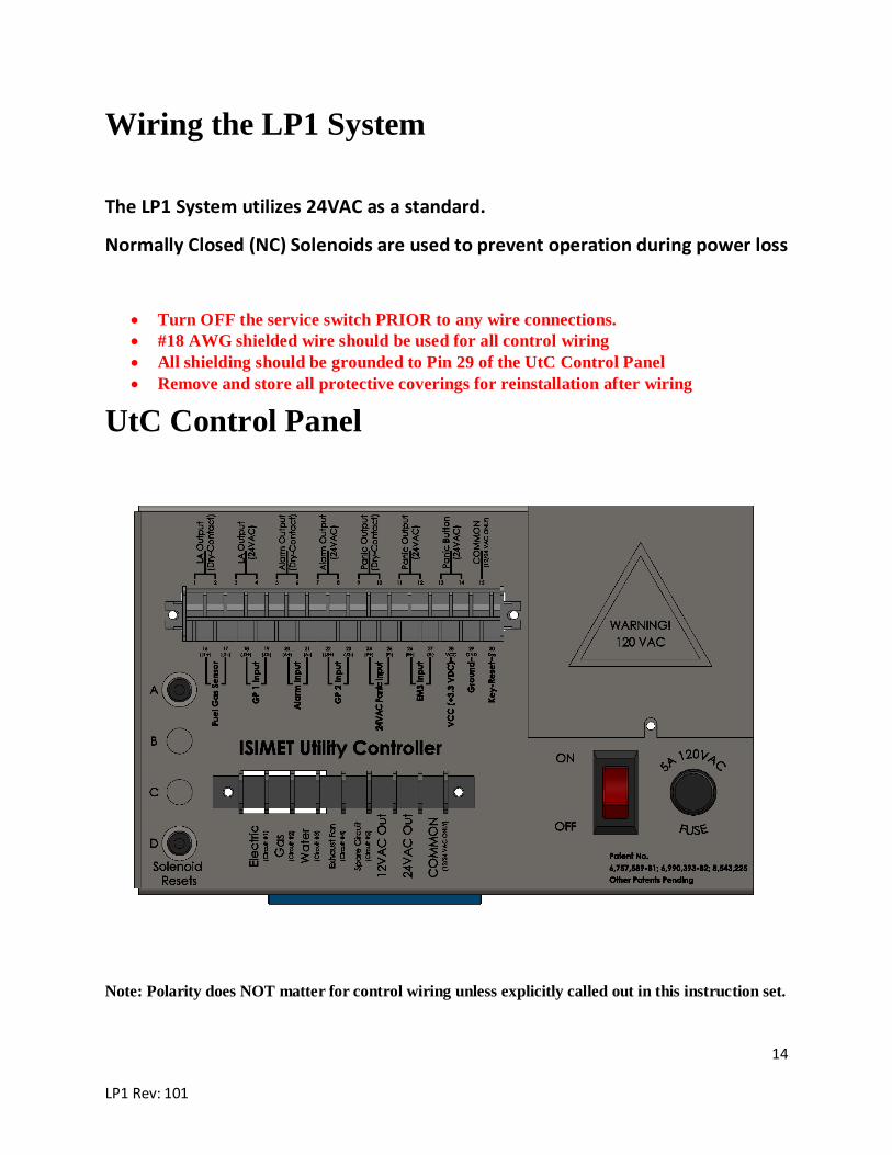
Wiring the LP1 System
The LP1 System utilizes 24VAC as a standard.
Normally Closed (NC) Solenoids are used to prevent operation during power loss
• Turn OFF the service switch PRIOR to any wire connections. • #18 AWG shielded wire should be used for all control wiring • All shielding should be grounded to Pin 29 of the UtC Control Panel • Remove and store all protective coverings for reinstallation after wiring
UtC Control Panel
Note: Polarity does NOT matter for control wiring unless explicitly called out in this instruction set.

15
LP1 Rev: 101
Control Panel Terminal Definitions Main Terminal Electric (Circuit #1):
24VAC Output for the first circuit. Controlled by Switch 1 (typically Electrical) on the UtC Door Panel. Circuit should be connected to this terminal and the COMMON terminal.
Gas (Circuit #2): 24VAC Output for the second circuit. Controlled by Switch 2 (typically Gas) on the UtC Door Panel. Circuit should be connected to this terminal and the COMMON terminal.
Water (Circuit #3): 24VAC Output for the third circuit. Controlled by Switch 3 (typically Water) on the UtC Door Panel. Circuit should be connected to this terminal and the COMMON terminal.
Exhaust Fan (Circuit #4): 24VAC Output for the fourth circuit. Controlled by Switch 4 (typically Exhaust Fan) on the UtC Door Panel. Circuit should be connected to this terminal and the COMMON terminal.
Spare Circuit (Circuit #5): 24VAC Output for the fifth circuit. Can be configured to be controlled by either Switch 3 (typically Water) or by remote configuration. Any connection here requires proper configuration prior to any connection. Circuit should be connected to this terminal and the COMMON terminal.
12VAC Out: Nominal 12VAC Output between this terminal and COMMON.
24VAC Out: Nominal 24VAC Output between this terminal and COMMON.
COMMON (12/24VAC ONLY): Enables the continuous flow of AC voltage. This should ONLY be connected between existing 12VAC and/or 24VAC loads on the UtC Control Panel.
Control Wiring Terminal LA Output (Dry-Contact): Voltage free switched connection used for the LA Companion add-on.
LA Output (24VAC): 24VAC relay connection used for the LA Companion add-on.
Alarm Output (Dry-Contact): Voltage free switched connection which closes on Alarm.

16
LP1 Rev: 101
Alarm Output (24VAC): Outputs a 24VAC signal on Alarm.
Panic Output (Dry-Contact): Voltage free switched connection which closes on Panic.
Panic Output (24VAC): Outputs a 24VAC signal on Panic.
Panic Button (24VAC): Connects to one or more Normally Open (NO) Panic Buttons in parallel. These terminals output and receive a nominal 24VAC signal used to enable Panic.
COMMON (12/24VAC ONLY): Enables the continuous flow of AC voltage. This should ONLY be connected between existing 12VAC and/or 24VAC loads on the UtC Control Panel.
Fuel Gas Sensor: Connects to one or more ISIMET Fuel Gas Sensors.
GP 1 Input: Configurable General-Purpose Input.
Alarm Input: Configurable Alarm input to disable the UtC.
GP 2 Input: Configurable General-Purpose Input. Used to connect the Emergency Shower Monitor.
24VAC Panic Input: Configurable Panic input to disable the UtC.
EMS Input: Configurable Building Energy Management System input.
VCC (+3.3 VDC): 3.3VDC Output voltage between this terminal and ground.
Ground: Used EXCLUSIVELY for VCC and grounding the control wiring shielding. Do NOT connect to this point unless specifically told by ISIMET.
Key-Reset: Outputs a signal upon keying the UtC. Ex: Used to reset the Fuel Gas Sensor.

17
LP1 Rev: 101
Connecting the S-Series
Use 18/4 AWG shielded control wiring to connect these terminals. It is recommended to use wire labels to label each wire as they are being run.
UtC Control Panel S-Series Terminal
Gas COMMON (Pin 1) Water HOT WATER and COLD WATER (Pins 2 & 3)
Key-Reset (Pin 30) GAS (Pin 4)

18
LP1 Rev: 101
Connecting the E-Series and Exhaust Fan

19
LP1 Rev: 101
Note: Dashed lines indicate connections pre-made.

20
LP1 Rev: 101
Note: RIBMN24S has 2 output terminals while RIBMN24C has 3.
RIBMN24C UtC Control Panel E-Series Relay Electric (Circuit #1) RIBMN24C (Pin 1) Input
COMMON RIBMN24C (Pin 2) Input
E-Series RIBMN24C Relay Output E-Series Electric Contactor
Pin 1 Preconnected Pin 2 Preconnected Pin 3 Preconnected
RIBMN24S UtC Control Panel E-Series Relay
Spare Circuit (Circuit #5) RIBMN24S (Pin 1) Input COMMON RIBMN24S (Pin 2) Input
E-Series RIBMN24S Relay Output E-Series Electric Contactor
Pin 1 Exhaust Fan LOAD Pin 2 Exhaust Fan LINE
Contact Ratings: 15A General Use @ 125 VAC
10A General Use @ 277 VAC
½ HP @ 125 VAC
1 HP @ 250 VAC
¼ HP @ 277 VAC

21
LP1 Rev: 101
Connecting the Panic Button(s)
Multiple panic buttons can be attached to the UtC in parallel as long as they are Normally Opened (NO) emergency panic buttons.
UtC Control Panel Panic Button Panic Button 24VAC (Pin 13) PANIC BUTTON (Pin 1) Panic Button 24VAC (Pin 14) PANIC BUTTON (Pin 2)

22
LP1 Rev: 101
Fuel Gas Sensor
UtC Control Panel Fuel Gas Sensor Fuel Gas Sensor (Pin 16) CON1 (Pin 5) Fuel Gas Sensor (Pin 17) CON1 (Pin 6)
Key-Reset (Pin 30) CON1 (Pin 1) 12VAC Out CON1 (Pin 4) COMMON CON1 (Pin 2)

23
LP1 Rev: 101
Pressure Sensor (Transducer)
WARNING: Pressure Sensor cannot handle pressures exceeding 45 psi.
UtC Control Panel Pressure Sensor +VCC (12VDC) (Pin 28) +VCC (12VDC)
Ground (Pin 29) Ground Pressure Sensor (Input) (Pin 15) 4-20mA Output

24
LP1 Rev: 101
Emergency Shower Monitor
UtC Control Panel Emergency Shower Monitor GP 2 Input (Pin 24) CON4 (Pin 1) GP 2 Input (Pin 25) CON4 (Pin 3)
24VAC Out CON1 (Pin 1) COMMON CON1 (Pin 2)
Flow Switch Input (Black) CON1 (Pin 3) Flow Switch Input (White) CON1 (Pin 4)

25
LP1 Rev: 101
Monitoring Beacon
UtC Control Panel Emergency Monitor Beacon Alarm Output (24VAC) (Pin 7) Black Alarm Output (24VAC) (Pin 8) White

26
LP1 Rev: 101
(Optional) External Fire Alarm If configured, triggering Alarm will disable all utilities and require re-keying.
Installation Options and Method • 24VAC or 24VDC Input Signal from Alarm:
o REMOVE Jumper from JP05 o PLACE two Jumpers on JP11
• 5VAC or 5VDC Input Signal from Alarm: o PLACE Jumper on JP05 o PLACE two Jumpers on JP11
• No Input Signal (Dry-Contact) from Alarm: o REMOVE Jumper from JP05 o PLACE two Jumpers on JP11
27
LP1 Rev: 101
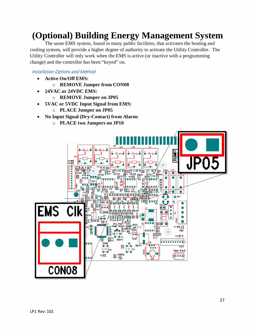
(Optional) Building Energy Management System The same EMS system, found in many public facilities, that activates the heating and
cooling system, will provide a higher degree of authority to activate the Utility Controller. The Utility Controller will only work when the EMS is active (or inactive with a programming change) and the controller has been “keyed” on.
Installation Options and Method • Active On/Off EMS:
o REMOVE Jumper from CON08 • 24VAC or 24VDC EMS:
o REMOVE Jumper on JP05 • 5VAC or 5VDC Input Signal from EMS:
o PLACE Jumper on JP05 • No Input Signal (Dry-Contact) from Alarm:
o PLACE two Jumpers on JP10

28
LP1 Rev: 101
NOTE: Be sure to replace the protective covering(s) after wiring the UtC!
Connecting Power to the UtC 1. Turn off the breaker supplying 120VAC to the UtC 2. Turn off the power switch on the UtC Control Panel 3. Remove the 120V cover from the UtC Control Panel 4. Connect the following wires:
• Green: Ground • White: Neutral • Black: 120VAC
5. Replace the UtC cover 6. DO NOT TURN ON POWER UNTIL COMPLETING THE START-UP PROCEDURE
STOP: Wait until walls are finished before continuing

29
LP1 Rev: 101
(Optional) Installing UtC and S-Series Trim Plate 1. Slide the trim plate over the enclosure.
2. Align holes on enclosure with upper and lower holes in door trim. 3. Insert four (4) 12-24 (provided) screws through enclosure panel and tighten into door trim.
Installing Covers 1. Install the included Stainless-Steel Covers for the Fuel Gas Sensor, Panic Button(s), Emergency
Shower Monitor, and Emergency Monitoring Beacon. 2. Install the E-Series Cover 3. Install the S-Series Door and ensure it is locked.

30
LP1 Rev: 101
Installing UtC Door Panel 1. Position the door at 90° – 100° of enclosure. (STEP 1) 2. Slide top hinge pin onto fixed hinge post at top of door. (STEP 2) 3. Slide lower hinge pin toward lower spring hinge mechanism with hinge pin lever in retract
position. (STEP 3) 4. With lower hinge pin in position, turn hinge pin lever outward and down, then turn inward to
the extend lock position. (STEP 4)
UtC Fuse Specifications
Used On Label Size Description 3A w/ Center Tap (12VAC)
Fuse 1
5 x 20 mm 2A Slow Blow
3A Transformer 3A Slow Blow 4A w/ Center Tap (12VAC) 3A Slow Blow 4A Transformer 4A Slow Blow Center Tap (12VAC) Only Fuse 2 5 x 20 mm 1A Slow Blow UtC Control Panel Control Panel Fuse 3AG 0.25” x 1.25” 5A/120VAC
NOTE: Fuse 2 is only used when 12VDC latching solenoids are used. The Control Panel Fuse is a fast-acting fuse.

31
LP1 Rev: 101
Acronyms and Common Terms
UtC: ISIMET Utility Controller
NFPA: National Fire Protection Agency
ADA: Americans with Disabilities Act
ISIMET: Innovating Systems Integrating Mechanical and Electrical Technology
EMS: Building Energy Management System
PCB: Printed Circuit Board
FGS: Fuel Gas Sensor
EMT: Electrical Metallic Tubing
E-Series: ISIMET Electrical Panel
S-Series: ISIMET Gas and Water Solenoid Panel