Embed Size (px)
Citation preview

Indust
rial E
lectr
ical Engin
eering a
nd A
uto
mation
CODEN:LUTEDX/(TEIE-5232)/1-079/(2007)
Islanding detection in power electronic converter based distributed generation
Daniel Persson
Dept. of Industrial Electrical Engineering and Automation Lund University

II
Abstract During the last decades the global warming and climate changes have been discussed in the media. Simultaneously the electricity consumers have experienced higher energy prices and the producers of electricity a rise in the energy consumption. These factors have strong impacts in the community and stimulate further integration of sustainable energy generation in the power system. Significant for distributed energy resources is utilization in the distribution grid at low or medium voltage level. If the utility grid is disconnected and an island in which the distributed generator is located is formed it is of great importance that also the distributed generator cease to generate power into the distribution network due to personal and equipment safety. This thesis project treats distributed generators interconnected with power electronic converters such as micro combined heat and power units and photovoltaic. The dynamic performance of this kind of distributed generation may maintain the voltage magnitude and frequency in an islanding condition if the load is well matched in reference to the generation. Passive islanding detection, which monitors the magnitude or frequency of the voltage, has non-detection zones. The UL 1741 [3] and IEEE 1547 [2] standards considers the performance of the islanding detection and treat a state with balance in power between load and generation. To pass previous mentioned islanding detection test active islanding detection is necessary. It is predictable that a performance based islanding test may be employed as a European standard. A European accepted standard based on performance would open doors for manufacturer and in the end the consumer can invest in a more reliable and safer product to install at lower cost. From a net owner point of view a safer distribution system would be beneficial. Active islanding detection methods perturb the distributed generators output power, which reduces the non-detection zones (dependability). On the other hand this injected variation of the output power may lead to decreased power quality and mal operations such as unnecessary tripping (security). The implemented active islanding detection device pulses a perturbation in order to fulfil the power quality and security requirements. The dependability is improved by a stationary error and an acceleration of an eventual error in the frequency that may rise between the inverter output current and the voltage over its terminals. The direction of the frequency drifting is determined according to the fundamental frequency of the grid to achieve a shorter detection time. By drifting the frequency in one direction the dependability and security performance are maintained when multiple generators are installed in the same radial feeder.

III
Table of Contents
INTRODUCTION 1
1.1 BACKGROUND 1 1.2 PROBLEM DEFINITION 2 1.3 APPROACH 3 1.4 REPORT OVERVIEW 4
DISTRIBUTED GENERATION 5
2.1 DISTRIBUTION SYSTEM WITH DISTRIBUTED GENERATION 5 2.2 POWER ELECTRONIC CONVERTER BASED DISTRIBUTED GENERATION 6
ISLANDING DETECTION IN DISTRIBUTION SYSTEM 11
3.1 ISLANDING 11 3.2 IMPORTANCE OF ISLANDING DETECTION 12 3.3 REQUIREMENTS OF ISLANDING DETECTION METHODS 12 3.4 PASSIVE DETECTION 13
ISLANDING DETECTION STANDARDS AND GUIDELINES 17
4.1 PASSIVE DETECTION 17 4.2 ACTIVE DETECTION 17 4.3 INTERVIEW WITH MANUFACTURER AND DEVELOPER OF DER 21 4.4 CONCLUDING REMARKS 21
ACTIVE ISLANDING DETECTION 23
5.1 IMPEDANCE MEASUREMENT 23 5.2 ACTIVE FREQUENCY DRIFT 23 5.3 ACTIVE FREQUENCY DRIFT WITH POSITIVE FEEDBACK 24 5.4 ACTIVE FREQUENCY DRIFT WITH PULSATION OF CHOPPING FRACTION 25 5.5 SUBHARMONIC IMPEDANCE MEASUREMENT WITH PULSATING AMPLITUDE 26 5.6 METHODS UTILIZING COMMUNICATION BETWEEN THE UTILITY AND THE INVERTER 26 5.7 ASSESSMENT OF ISLANDING DETECTION METHODS 27
SIMULATION MODEL 31
6.1 DISTRIBUTION NETWORK 31 6.2 INVERTER 32 6.3 ACTIVE ISLANDING DETECTION 34

IV
SIMULATIONS 37
7.1 CASE STUDIES 37 7.2 NORMAL OPERATION 38 7.3 ISLANDING 41 7.4 ASYNCHRONOUS MOTOR START 43 7.5 SHORT CIRCUIT IN LV DISTRIBUTION GRID 46
CONCLUSIONS AND RECOMMENDATIONS 51
8.1 INTRODUCTION 51 8.2 RESEARCH RESULTS 51 8.3 RECOMMENDATIONS FOR FURTHER RESEARCH 53
REFERENCES 55
APPENDIX A IEC 62116 ISLANDING DETECTION TEST 59
APPENDIX B DATA APPLIED IN MODEL 61
APPENDIX C PARK VECTOR TRANSFORMATION 67

V
Preface This report is the result of my master thesis research project within the field of electrical engineering. During the second half of my master program I chose to specialise within the field of power system technology. The project is collaboration between the department of Industrial Electrical Engineering and Automation at Lund Institute of Technology and Turbec R&D. The project has lasted from September 2006 until January 2007. The work has been performed at Turbec R&D who is a developer of micro turbines. Distributed generation is more and more installed in the electricity system. Therefore standards concerning safety in the distribution system are being more important. Turbec R&D has interest of what can be expected of future standards considering islanding detection in distributed generation. Another interesting aspect is how to meet future requirement in order to facilitate further integration of distributed generation in the power system. A licentiate thesis project treating passive islanding detection in wind power plants was performed by Tech. Lic. Niklas Stråth at Lund Institute of Technology [25]. That project can be seen as a point of departure for this project. This report describes the research of my graduation project and gives its conclusions and recommendations. The document may be a point of departure for further research project since the installation of Distributed generation is expected to continue and the safety is an important aspect. I hope this report gives an introduction to the topic and stimulate further work within standardisation and active islanding detection. Acknowledgements First of all I would like to express my gratitude to Tor Göransson who has been my supervisor at Turbec R&D. Tor helped me when I needed to discuss questions that rose during the project in a way that was developing both in a professional and personal plane. He was able to see things in a different perspective that led to enlightening conclusions. I am also very grateful to my supervisor at Lund Institute of Technology, Professor Sture Lindahl. His long experience within power systems has been of great importance. He has also inspired me continue to seeking answers to questions. I would like to express my gratitude to Fronius (Austria) for giving me answers and opinions regarding European standards and requirements treating islanding detection applicable for Photovoltaic systems.
VI
Furthermore I would like to thank Professor Olof Samuelsson at Lund Institute of Technology for initiating this project and the department of Industrial Electrical Engineering and Automation at Lund Institute of Technology and Turbec R&D for offering me this project. I thank those who have contributed with data to the simulation model and everybody that has helped me during this project. I also would like to thank my co-workers at Turbec R&D for a nice time. Thanks to my family for encouraging me to study and meet challenges. Malmö, 14th February 2007 Daniel Persson Author’s address Daniel Persson Industriell Elektroteknik och Automation Lunds Tekniska Högskola Box 118 SE-221 00 LUND Sweden Email [email protected]

VII
Abbreviations Symbol or Abbreviation Unit or Term
A Ampere
AFD Active Frequency Drift
AFDPF Active Frequency Drift with Positive Feedback
AFDPCF Active Frequency Drift with Pulsation of Chopping
Fraction
AM Asynchronous (Induction) Motor
cf Chopping Fraction
Dependability The probability for a protection of not having a failure to
operate under given conditions for a given time interval
DG Distributed Generation
DER Distributed Energy Resource
EMC Electromagnetic Compatibility
EPS Electric Power System
Hz Hertz
IINV Inverter output current
LV Low Voltage, < 1 kV AC
MV Medium Voltage, 1 kV AC < MV < 35 kV AC
NDZ Non-Detection Zone
OF Over Frequency
P Active Power (W)
PBLG Power Balanced Load Generation
PE Power Electronics
PEC Power Electronic Converter
PF Power Factor
PLL Phase Locked Loop
PQ Power Quality
PV Photovoltaic
PWM Pulse Width Modulation
Q Reactive Power (VAr)
ROCOF Rate Of Change Of Frequency

VIII
Security The probability of not having an unwanted operation
under given conditions for a given time interval
THD Total Harmonic Distortion
UF Under Frequency
V Voltage
VA Volt Ampere
VMP Voltage Magnitude and Frequency
var volt ampere reactive
VMP Voltage at the Measurement Point
W Watt
Ω Ohm
1
Chapter 1
Introduction
1.1 Background By ratification of the Kyoto protocol [11] a significant number of countries agreed in reducing their collective emissions of greenhouse gases. By reducing the energy consumption together with an optimization of the utilization of fossil fuels and renewable energy step towards a sustainable society is taken. In general during the last decades the energy consumers have experienced higher energy prices and the producers of energy an increase in energy consumption. These problems may be mitigated by implementing improvements in the electricity grid. Reducing electricity consumption is mainly a quest for consumers and may be encouraged by the government. In order to achieve optimized electricity production, increase the production and improve the security of electricity supply to the customers Distributed generation (DG) is an excellent alternative. Significant for DG is interconnection in low voltage (LV, < 1 kV ) or medium voltage (MV, 1 kV < MV < 35 kV) electricity grid. Power plants located in the distribution system geographically closer the consumer minimises transmission losses. Smaller DG plants applying fossil fuel for production of both electricity and heat (CHP) increases the overall efficiency by using the heat locally. DG may also be renewable energy sources as biogas (CHP), photovoltaic (PV) and wind power. The introduction of DG changes the power flow from a centralised higher to lower voltage level flow into a bidirectional power flow. When designing the distribution system the aspect of generation in the distribution system was not considered. If the utility grid is disconnected from the distribution grid (i.e. as a consequence of a short circuit) an unintentional island is formed and of great importance that the distributed power generation is disconnected from the utility grid. This is due to both personal and equipment safety. The main focus of this project is to improve detection of unintentional islanding.
2 Chapter 1 Introduction
Islanding detection in power electronic converter based distributed generation – Daniel Persson
1.2 Problem definition The introduction of DG has many impacts on the power system. Standards and requirements concerning this have been formed in purpose of maintaining a safe and reliable power system. Passive islanding detection monitors the voltage magnitude and frequency (VMF) over the interconnection terminals. When employing Power electronic converter (PEC) based DG such as µCHP and PV non-detection zones (NDZ) in passive islanding detection exists in a state of power balanced load and generation (PBLG) in the distribution system [12]. Active islanding detection, which perturb the output power (current) supplied from the DG unit to the distribution grid, reduces the NDZ. Perturbing the output power may though during some events lead to unnecessary trips (impedance method sector 5.1). Dependability is the capability of detecting unintentional islanding and security the capability of reject disturbances. European standards include various requirements concerning islanding detection in DG. For a manufacture of DG it is essential to be up to date regarding requirements and future trends within the field in order to maintain market share.
1.2.1 Objectives This master thesis project focuses on the unintentional islanding problem in distribution systems with distributed generation. The main research questions, which have to be answered, can therefore be stated as: What require present European standards concerning unintentional islanding with distributed generation and what could be extended in future coming standards? What islanding detection methods have potential to fulfil future requirements with acceptable dependability and security? The final answers to these central questions will be found in the conclusion and recommendations chapter (Chapter 8).
1.2.2 Boundary Conditions To limit the scope of the project, boundary conditions were set during first phase of the project, these conditions are discussed below.
The focus of interest is on detecting an unintentional islanding state, steps to be taken after this state is not treated.
This report treats Power electronic converter based distributed generation, such
as micro turbines and photovoltaic. The inverter (DC/AC PEC) is operated at full power output. Doubly fed induction generators are not included.

Chapter 1 Introduction 3
Islanding detection in power electronic converter based distributed generation - Daniel Persson
The implementation of the Distributed energy resource (DER) only includes operating in grid parallel mode. No concern has been taken on the DC-link side of the inverter. The inverter is implemented in simulation program by utilizing controlled current sources instead of as in the real case pulse width modulation employing semiconductor components. The output power of the distributed energy resource is controlled in a load following scenario, meaning almost no power is exported/imported from the owner of the distributed energy resource into the grid.
No overcurrent protection is implemented and studied. This protection is of
major importance when the grid is re connected before islanding is detected and the distributed generator is disconnected. This state may occur when automatic circuit reclosing are employed in the switching devices.
The proposed active islanding detection method is assessed. The performance of
other islanding detection methods is not evaluated.
1.3 Approach In order to answer the research questions in section 1.2.1 a strategy with the following steps is derived.
Literature study islanding detection standards The European standards have various requirements concerning islanding detection thresholds, time interval and methods. International organisations (UL, IEEE and IEC) have specific islanding detection type tests including a power balance in load and generation. A discussion with manufacture is also included in this step.
Literature study on active and passive islanding detection methods
Various islanding detection methods with different detecting methods exist. An assessment of islanding detection methods has been performed to determine the most suitable detection method.
Implementing a dynamic simulation model
A generic representation of a low voltage distribution system containing a power electronic converter interfaced distributed energy resource. Various simulation cases should be viable. The proposed islanding detection device is implemented in the control loop of the distributed energy resource. The data in the model is based on real measurements.
Perform simulations with proposed islanding detection method
Assess the islanding detection device during realistic contingencies in the low voltage distribution grid.

4 Chapter 1 Introduction
Islanding detection in power electronic converter based distributed generation – Daniel Persson
1.4 Report Overview This report is structured around the following chapters. Chapter 2 to gives an introduction to distributed generation and describes the basics of micro turbine and photovoltaic technology. In chapter 3 islanding and its impacts is explained. The most common passive islanding detection methods are also included in this chapter. Chapter 4 discuss existing standards and future trends within islanding detection. Information and an assessment of active islanding detection methods may be read in chapter 5. The implemented simulation model is described in chapter 6. The algorithm of the proposed islanding detection is explained as well. The simulation cases are determined and the results illustrated in chapter 7. Finally chapter 8 give the conclusion and answers on the research questions and recommendations for further research within this field.

5
Chapter 2
Distributed generation
2.1 Distribution system with distributed generation The electric power system is developing from a system with large centralised generators into a system with smaller generators interconnected at lower voltage levels. The power flow is thus changed from centralised into bidirectional power flow (Figure 2.1 and Figure 2.2). Energy resources interconnected in the MV or LV distribution grid is known as Distributed Generation (DG) [21], [22], [27] other common names are decentral, dispersed or embedded generation.
Figure 2.1 Power system with centralised generation (Source [26])
Some distributed generators apply sustainable energy i.e. micro turbines (biogas, optimised use of fossil fuel, CHP), wind power and photovoltaic. These energy resources facilitate to comply with the Kyoto protocol. Distributed generation also increase the volume of produced power which may be the solution to meet increased power consumption in the society. By generating power locally the energy efficiency increases due to reduced transmission losses.
Figure 2.2 Decentralised power system (Source [27])
6 Chapter 2 Distributed generation
Islanding detection in power electronic converter based distributed generation – Daniel Persson
The installation process is shorter for DG than for large centralised plants i.e. nuclear power plants. Customers are also given the opportunity to produce their own electricity in order to reduce their energy expenses. The location of the distributed energy resource (DER) has thus many impacts. By injecting power locally the voltage gains in that interconnection point. This can compensate for voltage sags but may also lead to over voltage problems. The production rate of distributed generation might in some cases have correlation to the weather conditions. The power generated from wind is dependent of the wind speed and the production rate from a photovoltaic cell depends on the sun irradiation. During cold weather conditions the heat production may increase and in CHP plants the power production then also increases. A certain unpredictability of distributed generated power is introduced due to the weather correlation.
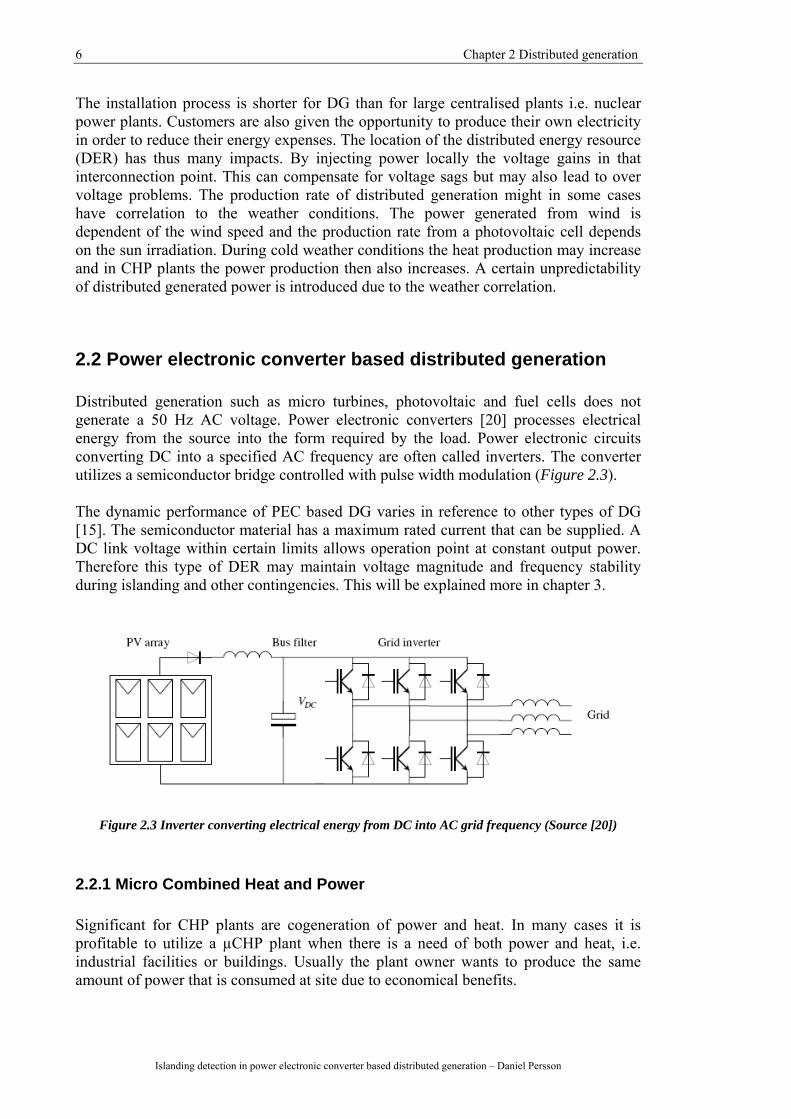
2.2 Power electronic converter based distributed generation Distributed generation such as micro turbines, photovoltaic and fuel cells does not generate a 50 Hz AC voltage. Power electronic converters [20] processes electrical energy from the source into the form required by the load. Power electronic circuits converting DC into a specified AC frequency are often called inverters. The converter utilizes a semiconductor bridge controlled with pulse width modulation (Figure 2.3). The dynamic performance of PEC based DG varies in reference to other types of DG [15]. The semiconductor material has a maximum rated current that can be supplied. A DC link voltage within certain limits allows operation point at constant output power. Therefore this type of DER may maintain voltage magnitude and frequency stability during islanding and other contingencies. This will be explained more in chapter 3.
Figure 2.3 Inverter converting electrical energy from DC into AC grid frequency (Source [20])
2.2.1 Micro Combined Heat and Power Significant for CHP plants are cogeneration of power and heat. In many cases it is profitable to utilize a µCHP plant when there is a need of both power and heat, i.e. industrial facilities or buildings. Usually the plant owner wants to produce the same amount of power that is consumed at site due to economical benefits.
Chapter 2 Distributed generation 7
Islanding detection in power electronic converter based distributed generation - Daniel Persson
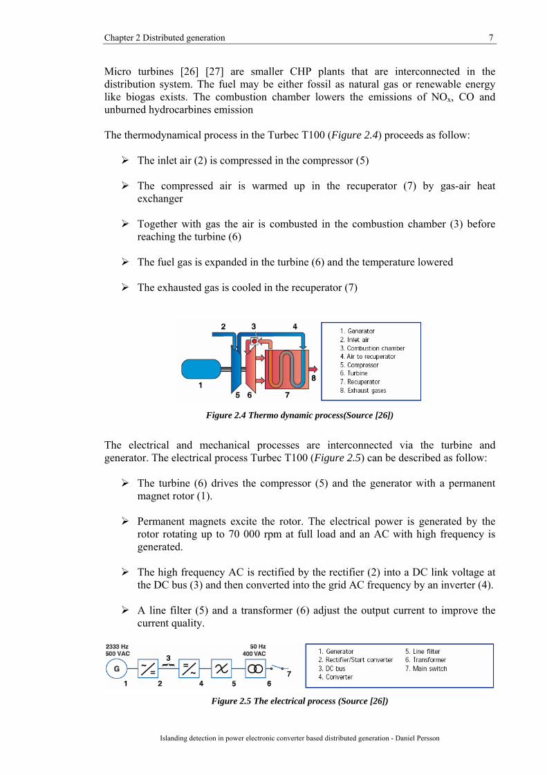
Micro turbines [26] [27] are smaller CHP plants that are interconnected in the distribution system. The fuel may be either fossil as natural gas or renewable energy like biogas exists. The combustion chamber lowers the emissions of NOx, CO and unburned hydrocarbines emission The thermodynamical process in the Turbec T100 (Figure 2.4) proceeds as follow:
The inlet air (2) is compressed in the compressor (5)
The compressed air is warmed up in the recuperator (7) by gas-air heat exchanger
Together with gas the air is combusted in the combustion chamber (3) before
reaching the turbine (6)
The fuel gas is expanded in the turbine (6) and the temperature lowered
The exhausted gas is cooled in the recuperator (7)
Figure 2.4 Thermo dynamic process(Source [26])
The electrical and mechanical processes are interconnected via the turbine and generator. The electrical process Turbec T100 (Figure 2.5) can be described as follow:
The turbine (6) drives the compressor (5) and the generator with a permanent magnet rotor (1).
Permanent magnets excite the rotor. The electrical power is generated by the
rotor rotating up to 70 000 rpm at full load and an AC with high frequency is generated.
The high frequency AC is rectified by the rectifier (2) into a DC link voltage at
the DC bus (3) and then converted into the grid AC frequency by an inverter (4).
A line filter (5) and a transformer (6) adjust the output current to improve the current quality.
Figure 2.5 The electrical process (Source [26])
8 Chapter 2 Distributed generation
Islanding detection in power electronic converter based distributed generation – Daniel Persson
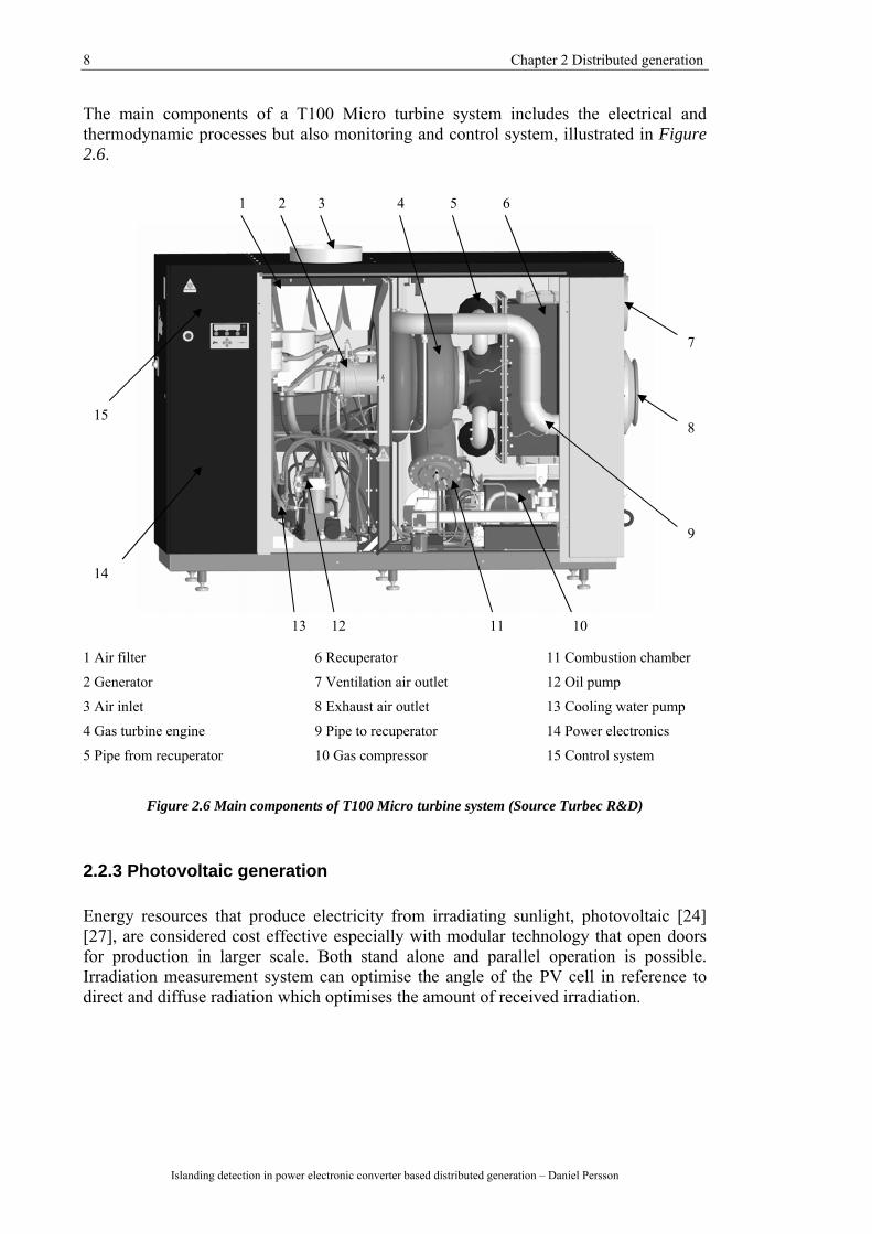
The main components of a T100 Micro turbine system includes the electrical and thermodynamic processes but also monitoring and control system, illustrated in Figure 2.6.
1 Air filter 6 Recuperator 11 Combustion chamber
2 Generator 7 Ventilation air outlet 12 Oil pump
3 Air inlet 8 Exhaust air outlet 13 Cooling water pump
4 Gas turbine engine 9 Pipe to recuperator 14 Power electronics
5 Pipe from recuperator 10 Gas compressor 15 Control system
Figure 2.6 Main components of T100 Micro turbine system (Source Turbec R&D)
2.2.3 Photovoltaic generation Energy resources that produce electricity from irradiating sunlight, photovoltaic [24] [27], are considered cost effective especially with modular technology that open doors for production in larger scale. Both stand alone and parallel operation is possible. Irradiation measurement system can optimise the angle of the PV cell in reference to direct and diffuse radiation which optimises the amount of received irradiation.
7
8
9
1 2 3 4 5 6
101112 13
14
15
Chapter 2 Distributed generation 9
Islanding detection in power electronic converter based distributed generation - Daniel Persson
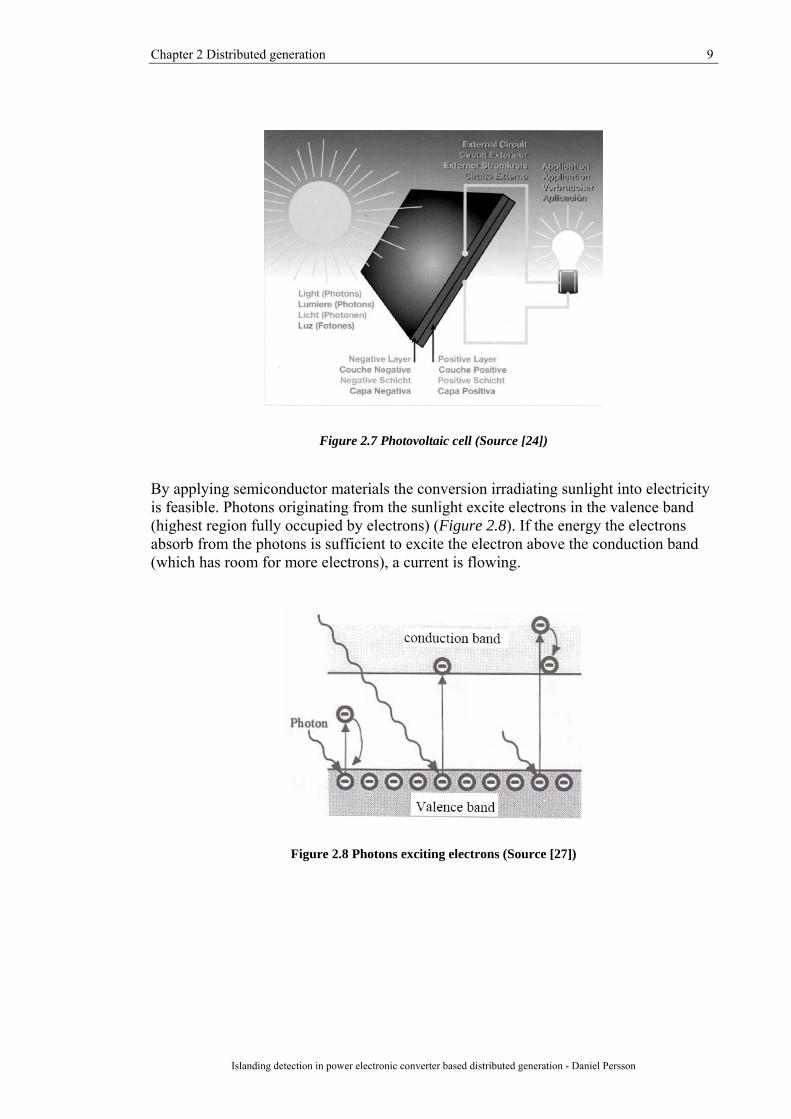
Figure 2.7 Photovoltaic cell (Source [24])
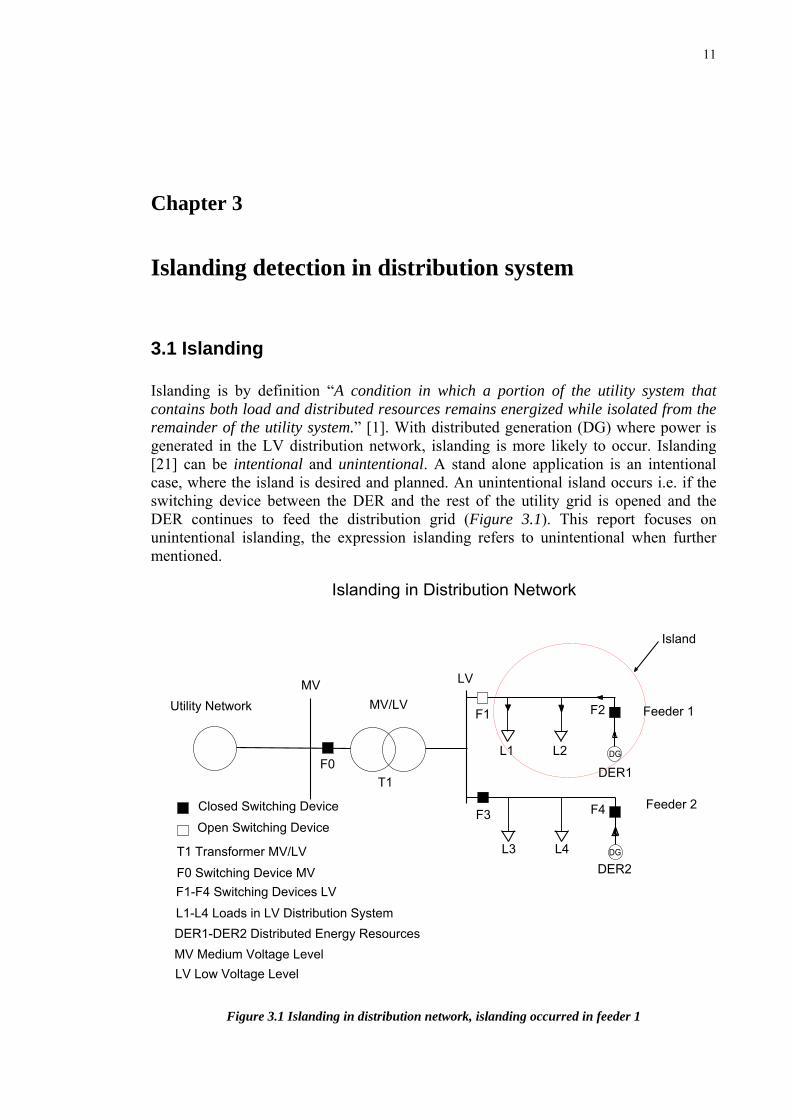
By applying semiconductor materials the conversion irradiating sunlight into electricity is feasible. Photons originating from the sunlight excite electrons in the valence band (highest region fully occupied by electrons) (Figure 2.8). If the energy the electrons absorb from the photons is sufficient to excite the electron above the conduction band (which has room for more electrons), a current is flowing.
Figure 2.8 Photons exciting electrons (Source [27])

11
Chapter 3
Islanding detection in distribution system
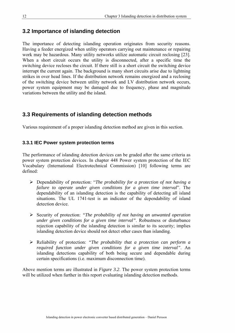
3.1 Islanding Islanding is by definition “A condition in which a portion of the utility system that contains both load and distributed resources remains energized while isolated from the remainder of the utility system.” [1]. With distributed generation (DG) where power is generated in the LV distribution network, islanding is more likely to occur. Islanding [21] can be intentional and unintentional. A stand alone application is an intentional case, where the island is desired and planned. An unintentional island occurs i.e. if the switching device between the DER and the rest of the utility grid is opened and the DER continues to feed the distribution grid (Figure 3.1). This report focuses on unintentional islanding, the expression islanding refers to unintentional when further mentioned.
Figure 3.1 Islanding in distribution network, islanding occurred in feeder 1
12 Chapter 3 Islanding detection in distribution system
Islanding detection in power electronic converter based distributed generation – Daniel Persson
3.2 Importance of islanding detection The importance of detecting islanding operation originates from security reasons. Having a feeder energized when utility operators carrying out maintenance or repairing work may be hazardous. Many utility networks utilize automatic circuit reclosing [23]. When a short circuit occurs the utility is disconnected, after a specific time the switching device recloses the circuit. If there still is a short circuit the switching device interrupt the current again. The background is many short circuits arise due to lightning strikes in over head lines. If the distribution network remains energized and a reclosing of the switching device between utility network and LV distribution network occurs, power system equipment may be damaged due to frequency, phase and magnitude variations between the utility and the island.
3.3 Requirements of islanding detection methods Various requirement of a proper islanding detection method are given in this section.
3.3.1 IEC Power system protection terms The performance of islanding detection devices can be graded after the same criteria as power system protection devices. In chapter 448 Power system protection of the IEC Vocabulary (International Electrotechnical Commission) [10] following terms are defined:
Dependability of protection: “The probability for a protection of not having a failure to operate under given conditions for a given time interval”. The dependability of an islanding detection is the capability of detecting all island situations. The UL 1741-test is an indicator of the dependability of island detection device.
Security of protection: “The probability of not having an unwanted operation
under given conditions for a given time interval”. Robustness or disturbance rejection capability of the islanding detection is similar to its security; implies islanding detection device should not detect other cases than islanding.
Reliability of protection: “The probability that a protection can perform a
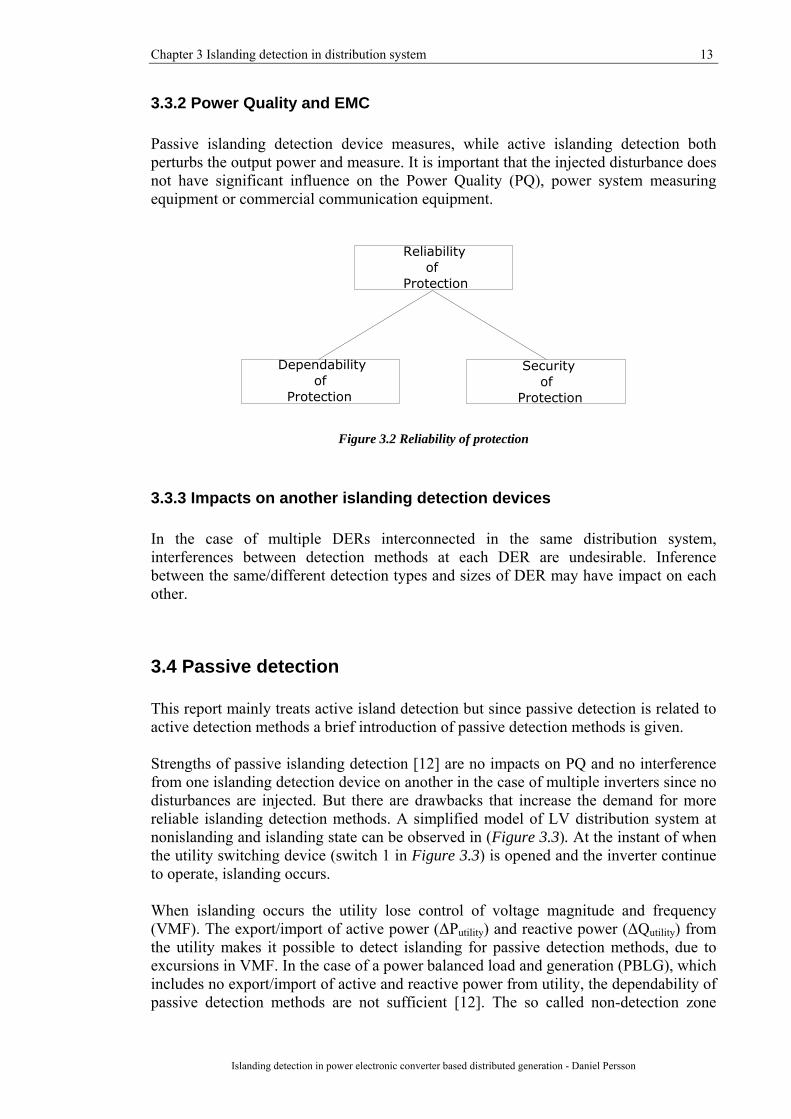
required function under given conditions for a given time interval”. An islanding detections capability of both being secure and dependable during certain specifications (i.e. maximum disconnection time).
Above mention terms are illustrated in Figure 3.2. The power system protection terms will be utilized when further in this report evaluating islanding detection methods.
Chapter 3 Islanding detection in distribution system 13
Islanding detection in power electronic converter based distributed generation - Daniel Persson
3.3.2 Power Quality and EMC Passive islanding detection device measures, while active islanding detection both perturbs the output power and measure. It is important that the injected disturbance does not have significant influence on the Power Quality (PQ), power system measuring equipment or commercial communication equipment.
Figure 3.2 Reliability of protection
3.3.3 Impacts on another islanding detection devices In the case of multiple DERs interconnected in the same distribution system, interferences between detection methods at each DER are undesirable. Inference between the same/different detection types and sizes of DER may have impact on each other.
3.4 Passive detection This report mainly treats active island detection but since passive detection is related to active detection methods a brief introduction of passive detection methods is given. Strengths of passive islanding detection [12] are no impacts on PQ and no interference from one islanding detection device on another in the case of multiple inverters since no disturbances are injected. But there are drawbacks that increase the demand for more reliable islanding detection methods. A simplified model of LV distribution system at nonislanding and islanding state can be observed in (Figure 3.3). At the instant of when the utility switching device (switch 1 in Figure 3.3) is opened and the inverter continue to operate, islanding occurs. When islanding occurs the utility lose control of voltage magnitude and frequency (VMF). The export/import of active power (ΔPutility) and reactive power (ΔQutility) from the utility makes it possible to detect islanding for passive detection methods, due to excursions in VMF. In the case of a power balanced load and generation (PBLG), which includes no export/import of active and reactive power from utility, the dependability of passive detection methods are not sufficient [12]. The so called non-detection zone

14 Chapter 3 Islanding detection in distribution system
Islanding detection in power electronic converter based distributed generation – Daniel Persson
(NDZ) is much larger for passive than for active islanding detection methods. Another problem for some detection method is its security. Threshold values chosen in reference to dependability may decrease the security of the detection method.
Figure 3.3 Nonislanding and islanding circuit. Note if IINV >ILOAD, IINV will flow towards ZLINE
Over/Under VMF detection devices are applied in other applications hence benefits of utilizing those methods. The most important passive detection methods for later understanding of active detection methods are presented below.
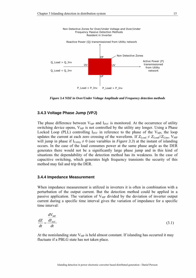
3.4.1 Over/Under Voltage Amplitude (O/U VA) Islanding is detected when the amplitude of VMP (Figure 3.3) is out of a pre specified interval of voltage amplitude. The amplitude of the voltage at the measurement point (VMP) fluctuates when ΔPutility ≠ 0 [12]. The NDZ of this method occurs close the PBLG state (Figure 3.4).
3.4.2 Over/Under Voltage Frequency (O/U VF) and Rate of Change of Frequency (ROCOF) This method monitors the frequency of VMP, when out of bounds, islanding is detected. At the instant of ΔQutility ≠ 0 VMP will alter in phase in reference to its previous value [12]. The control system of the inverter will change the phase of the output current (IINV) to keep the reactive power (QINV) close to its reference value in order to deliver power with the pre specified power factor (PF). If the local load consumes power with a PF that the DER can not supply, there will be a phase difference between IINV and VMP. This difference will either increase or decrease the period time of the waveform which in turn will change the frequency of the VMP. The output power supplied by the DER has a certain PF. If the load consumes power with a PF different from power supplied from the DER, the frequency of VMP will drift away from utility fundamental frequency. This detection method has NDZ which occurs close a PBLG state (illustrated in Figure 3.4). The time for reaching O/U VF limits is depending of the reactive power control loop and may have impacts on the detection methods dependability. A df/dt detection method (ROCOF) [22] might decrease the detection time.
Chapter 3 Islanding detection in distribution system 15
Islanding detection in power electronic converter based distributed generation - Daniel Persson
Figure 3.4 NDZ in Over/Under Voltage Amplitude and Frequency detection methods
3.4.3 Voltage Phase Jump (VPJ) The phase difference between VMP and IINV is monitored. At the occurrence of utility switching device opens, VMP is not controlled by the utility any longer. Using a Phase Locked Loop (PLL) controlling IINV in reference to the phase of the VMP, the loop updates the current at each zero crossing of the waveform. If ZLoad ≠ ZLoad//ZLine, VMP will jump in phase if IUtility ≠ 0 (see variables in Figure 3.3) at the instant of islanding occurs. In the case of the load consumes power at the same phase angle as the DER generates there would not be a significantly large phase jump and in this kind of situations the dependability of the detection method has its weakness. In the case of capacitive switching, which generates high frequency transients the security of this method may fail and trip the DER.
3.4.4 Impedance Measurement When impedance measurement is utilized in inverters it is often in combination with a perturbation of the output current. But the detection method could be applied in a passive application. The variation of VMP divided by the deviation of inverter output current during a specific time interval gives the variation of impedance for a specific time interval:
dtdIdV
dtdZ InV
MP
= (3.1)
At the nonislanding state VMP is held almost constant. If islanding has occurred it may fluctuate if a PBLG state has not taken place.

17
Chapter 4
Islanding detection standards and guidelines The electric power system was not designed for DG. Introducing DERs in the distribution system, operated in parallel with the utility network has many impacts. If the switching device between the DER and the rest of the power system is opened an unintended island may occur. Personal safety, equipment protection and power quality are some of the important aspects which have to be considered [1]. Many international/national standards/guidelines are available [1]-[9]. In this chapter some of them will be mentioned. This report mainly includes active island detection but a short introduction of the interconnection standards for passive island detection methods will be given.
4.1 Passive detection Passive detection methods monitor VMF at the interconnection point of the DER. Several countries in Europe have decided their own thresholds for the deviation of VMF that is allowed and maximum disconnection time of the DER. Rate of change of frequency (ROCOF) and Vector shift methods are also required in some European national standards [4]-[7].
4.2 Active detection Problem can arise in the isolated part of the Electric Power System (EPS) when using passive island detection methods if a PBLG state is achieved, due to no VMF deviation [1]. The probability of having PBLG varies dependable on the size of installed DG in the LV distribution net. If the range of the generation covers the load, the probability of ending in the state of PBLG exists. All conventional passive islanding detection methods have Non Detection Zones (NDZ), where an unintended island is not detected. Therefore more advanced methods that contribute to smaller NDZ are needed. Active methods vary an output parameter of the DER and detect the disturbance by a passive detection system. The perturbation of the output power makes is possible to detect islanding during a PBLG state and reduces the NDZ significantly.
18 Chapter 4 Island detection standards and guidelines
Islanding detection in power electronic converter based distributed generation – Daniel Persson
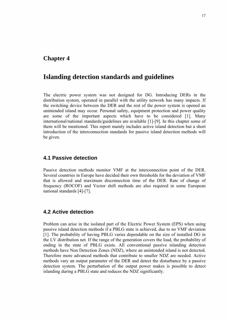
4.2.1 UL 1741 Both UL (Underwriters Laboratories Inc.) and IEEE (The Institute of Electrical and Electronics Engineering, Inc) have an islanding detection standard test for DER [2], [3]. The tests were from the beginning limited for smaller DER units but in IEEE Std. 1547 units with a maximum capacity of 10 MVA or less are included. The UL test is representative due to its test circuit are used in other test (IEEE 1547 and IEC 62116). The local load in the LV distribution grid is modelled as a RLC parallel circuit. The parameters (RLC) have to be tuned into PBLG prior the island detection test. Test circuit can be seen in Figure 4.1 below. A short description of the method is described below, for further information see [3]. The quality factor of islanded load circuit is given by:
LCRQ = (4.1)
R effective load resistance (Ω) C effective load capacitance (F) L effective load inductance (H) or
qCqL PPP
Q **1= (4.2)
PqL reactive power consumed by inductive load component (kvar) PqC reactive power consumed by capacitive load component (kvar) P real power (kW) Before the test the resonant frequency of the load circuit has to be equal the inverter rated frequency under the condition Q ≤ 2.5.
LCf
π21
= (4.3)
f resonant frequency of the load in islanded circuit (Hz)
Figure 4.1 Test Circuit for anti islanding test.
Chapter 4 Island detection standards and guidelines 19
Islanding detection in power electronic converter based distributed generation - Daniel Persson
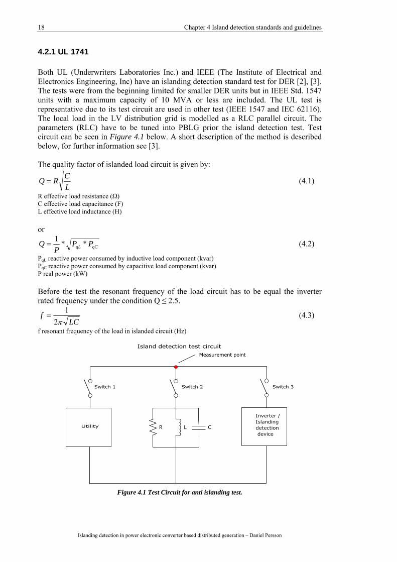
Before the islanding detection test a VMF test is performed to verify correct tuning of protection relays, Table 4.1 specifies different conditions that has to be accomplished. Each condition are tested 10 times, during each tripping the time is also measured from when the switch 1 is open until the inverter stop exporting current to the load. If one test is failed the whole test is failed.
Voltage and frequency test conditions Measurement point in test circuit Maximum trip time in a 60 Hz network (a)
Condition Voltage, V Frequency, Hz Cycles (60 HZ) Time, s A V < 0.5Vn (b) rated 6 0.1 B 0.5Vn ≤ V < 0.88Vn rated 120 2 C 0.88Vn ≤ V < 1.10Vn rated No cessation No cessation D 1.10Vn ≤ V < 1.37Vn rated 120 2 E 1.37Vn ≤ V rated 2 2/60 F rated f < fn - 0.7 (c) 6 0.1 G rated fn + 0.5 < f 6 0.1
(a) Trip time refers to maximum time after switch 1 has been opened before cessation of the current delivered to measurement point (in all phases) during a specific condition, in network with nominal frequency other than 60 Hz the maximum number of cycles must not exceed the maximum number of cycles allowed in a 60 Hz network (b) Vn = nominal phase voltage (line to neutral) (c) fn = nominal frequency, with df/dt < 0.5 Hz/s
Table 4.1 , Voltage and frequency test conditions.
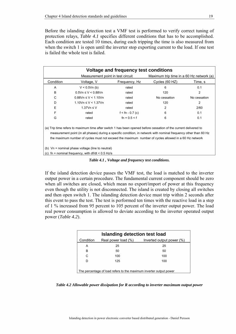
If the island detection device passes the VMF test, the load is matched to the inverter output power in a certain procedure. The fundamental current component should be zero when all switches are closed, which mean no export/import of power at this frequency even though the utility is not disconnected. The island is created by closing all switches and then open switch 1. The islanding detection device must trip within 2 seconds after this event to pass the test. The test is performed ten times with the reactive load in a step of 1 % increased from 95 percent to 105 percent of the inverter output power. The load real power consumption is allowed to deviate according to the inverter operated output power (Table 4.2).
Islanding detection test load Condition Real power load (%) Inverted output power (%)
A 25 25 B 50 50 C 100 100 D 125 100
The percentage of load refers to the maximum inverter output power
Table 4.2 Allowable power dissipation for R according to inverter maximum output power
20 Chapter 4 Island detection standards and guidelines
Islanding detection in power electronic converter based distributed generation – Daniel Persson
4.2.2 IEC 62116 IEC (International Electrotechnical Commission) promote international cooperation within standardizations for electrical and electronic issues. In the draft version of IEC 62116 (2006-08-04) Test procedure of islanding prevention measures for utility-interconnected photovoltaic inverters [8] a similar test as the UL requires is proposed. The test can also be utilized by other inverter interconnected DER. In the normative reference IEC 61727 (2004-12) [4] the ratings of the system valid in this standard has a rating of 10 kVA or less, the standard is though subject to revision. The test circuit is the same as in the UL test (Figure 4.1) and a PBLG tuning procedure in the RLC load takes place before the island detection test. The requirement for passing the test contains more test cases but the conditions for confirming island detection do not have a significant deviation compared to the UL test. The inverter is tested at three levels of output power (A 100-105%, B 50-66% and C 25-33% of inverters output power). Case A is tested under maximum allowable inverter input power, case C at minimum allowable inverter output power if > 33 %. The voltage at the input of the inverter also has specific conditions (see [8]). All conditions are to be tested at no deviation in real and reactive load power consumption then for condition A in a step of 5% both real and reactive power iterated deviation from -10% to 10% from operating output power of inverter. Condition B and C are evaluated by deviate the reactive load in an interval of ±5 % in a step of 1 % of inverter output power. Deviations in load consumption result in current flowing towards/from the utility switch. In total 47 cases (Appendix A) which all have to pass the island protection criteria in IEC 61727 [4] (voltage and frequency limits in Appendix B) or the national standard. The maximum trip time is the same as in UL and IEEE standards 2 s.
4.2.3 DIN VDE 0126-1-1 The German standard DIN VDE 0126-1-1 [9], [13] is the updated edition (February 2006) of DIN VDE 0126 from September 1999. The standard treats an islanding detection system ENS, “Die selbsttätig wirkende Freischaltstelle besteht aus zwei voneinander unabhängigen Einrichtungen zur Netzüberwachung mit zugeordnete allpoligen Schaltern in Reihe”. The detection method includes over/under voltage and frequency detection but also monitors the grid impedance. The impedance detection method is an active detection method due to a pulsed current injection from the inverter towards the utility network. The standard is extraordinary due to a specific active islanding detection method is mentioned, in the other standards no specific active method is required. The new impedance jump threshold 1.0 Ω/s was increased from previous value 0.5 Ω/s, also valid in Austrian norm ÖVE/ÖNORM 2750 (2004), hereby the rejection capability to nuisance tripping is improved. The versions of above mentioned standards also accept testing with a RLC circuit (used in UL 1741, IEEE 929 and IEC 62116). One drawback with the impedance monitoring is when multiple inverters interconnected in the same LV grid. Then the current injection from each inverter disturbs among each other and the ENS does not work properly. Problems occur also in general when components, which alter the grid impedance, are added in the network. Hence in
Chapter 4 Island detection standards and guidelines 21
Islanding detection in power electronic converter based distributed generation - Daniel Persson
Germany it is not allowed to apply ENS in an installation with an AC output power ≥ 30 kW.
4.3 Interview with manufacturer and developer of DER During the work with the interconnection standards a conversation with the PV-support at Fronius (Austria) took place [28]. In their PV-inverter an ENS card as islanding detection is applied. In countries where ENS is not accepted the impedance monitoring is disabled. As a manufacture of PV inverters Fronius is not satisfied with including the ENS in their units since it is an extra component to integrate that can cause problems and get damaged. Fronius believe that it will be difficult in Europe to agree in one standard concerning active detection methods and that more possibilities to measure will appear. Further information was gathered from Turbec R&D (Sweden) [29], which develops micro turbines applied in combined heat and power applications. Many micro turbine units are operated in a manner when the owner wants to supply his load but not export any power to the utility due to economical benefits (“Load following”). In a Load following scenario it is possible to end up in a PBLG state when utility network is disconnected (under the condition that the generation is equal the amount of active and reactive power consumed by the isolated circuit). Applying active islanding detection would minimize the NDZ and give a safer operation especially when PBLG situations can occur. With performance based standard tests it is possible to apply active detection that benefits Turbecs type of DER produced. Hence possible to produce a more reliable (increased disturbance rejection) product. Using performance based tests for certifying the type of unit would also implicate no need for test at site, which facilitates the installation. Turbec R&D would support a future standard allowing Power Electronic (PE) integrated islanding detection (allowed in Spain [14]), where no external relays is needed. No external relays imply lower installation cost of the product.
4.4 Concluding remarks The common denominator of the three standards mentioned in this chapter includes the performance test with a RLC load. A PBLG situation, which can occur, requires active island detection. Only the islanding detection capability (dependability) of the DER is tested. Simulation cases where the disturbance rejection of the DER (security) is not included in the standard test. Instead each national standard have different thresholds for different methods and disconnection times when the DER should cease to energize the LV network.
22 Chapter 4 Island detection standards and guidelines
Islanding detection in power electronic converter based distributed generation – Daniel Persson
One reason for the revision of German standard DIN VDE 0126 was the need of more security in the islanding detection. The revision also contained the option of testing the islanding detection device in a RLC circuit instead of the requirement using ENS with impedance detection method. This trend in Germany and Austria is of great importance in Europe hence a step towards performance based islanding detection certification is taken. An important aspect is the case of multiple active islanding detection devices in the same LV network. The present impedance detection in the ENS card has problem with this. Hence ENS impedance detection method is not allowed in the case of installations with an AC output power ≥ 30 kW. In a few years the demand of multiple DER in LV distribution network will increase and performance test may also include this ability. The performance based test opens doors for manufactures of DER. This in turn encourage the development of improved dependability and security in the islanding detection devices but also for the costumers who obtain a DER easier to install at lower costs. The ability of safer distribution system applying active islanding detection over wins the degradation in power quality issues from a net owner point of view.
23
Chapter 5
Active islanding detection Active islanding detection methods [12] have in common that a perturbation of the inverter output current is injected in the distribution network. The injected disturbance enhances the dependability and the NDZ can be significant reduced. The detection can be made significantly faster than in the case of passive detection. The drawbacks are degradation in PQ and implementing an additional function. In many cases the implementation can though be applied in the software controlling the power electronics, thus utilizing active islanding detecting methods may not include new hardware. The most interesting islanding detection methods for this project are presented below. Harmonic Amplitude Jump [12], Slip Mode Frequency Shift (SMS) [12], Positive Feedback on Voltage [12], Voltage Unbalance and Total Harmonic Distortion [18], Automatic Phase Shift [19] were also studied in this literature study but outside of the scope of this report.
5.1 Impedance measurement The inverter output current is generally varied in magnitude. These perturbations have impacts on the voltage at the measurement point (VMP). The perturbation does not significantly affect VMP when the utility is connected but some characteristic of VMP is changed when operated in islanding. The measurement method is explained in 3.4.4 and measures the difference in impedance. The performance [12] of this detection method can be seen as good in the case of a single DER inverter interconnected. At the occurrence of multiple inverters interconnected the current injections interfere with each other and the reliability of this detection method degrades significantly.
5.2 Active frequency drift The local load and distribution lines/cables in the islanding network consume a certain power. When utility feeding the LV network the phase of VMP is not significantly affected by IINV. In the case of utility disconnection VMP is controlled by IINV. The frequency of the inverter output current is estimated to lead or lag VMP with a predetermined ratio chopping fraction (cf) (Figure 5.1).

24 Chapter 5 Active islanding detection
Islanding detection in power electronic converter based distributed generation – Daniel Persson
Islanding changes the cf, since VMP is not controlled by the utility any longer. If a difference in cf is measured, the frequency of IINV is changed in order to reach predetermined reference value of cf. Then VMP will follow IINV and therefore cf will remain the same and the frequency of IINV will exceed the thresholds for abnormal values. In some cases of loads the dependability of Active Frequency Drift (AFD) is not acceptable and the detection time far too long.
Figure 5.1 Active frequency drift
VMP
Z
Ttcf 2
= (3.2)
cf chopping fraction tZ time deviation between VMP and IINV TVMP half the period time for VMP TIINV half the period time for IINV
5.3 Active frequency drift with positive feedback Due to the drawbacks of AFD further improvements have been done in Active Frequency Drift with Positive Feedback (AFDPF) [12]. The positive feedback loop increases the error between the instantaneous frequency of VMP and the fundamental grid frequency. The last sample of cf added with the amplified the error gives the next sample of cf. The purpose behind this extension is faster detection time and improved dependability. The drawback of this method is continuously reducing the PQ and with multiple inverters interconnected the PQ degradation will be more severe.
Chapter 5 Active islanding detection 25
Islanding detection in power electronic converter based distributed generation - Daniel Persson
)(1 linekkk ffFcfcf −+= − (3.3) cfk chopping fraction cfk-1 last sampled value of pulsated chopping fraction F feedback gain fk measured frequency of VMP fline utility fundamental frequency AFDPF together with AFDPCF are considered to have the strongest performance among islanding detection methods studied in this report (Table 5.1).
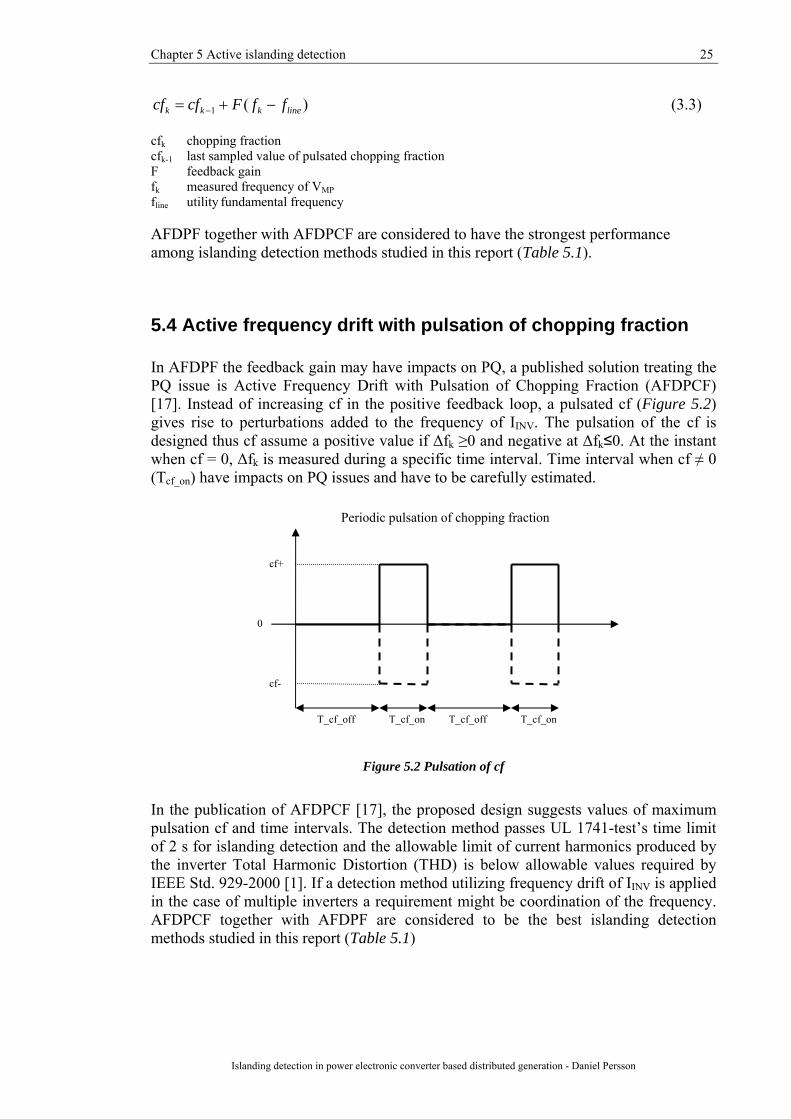
5.4 Active frequency drift with pulsation of chopping fraction In AFDPF the feedback gain may have impacts on PQ, a published solution treating the PQ issue is Active Frequency Drift with Pulsation of Chopping Fraction (AFDPCF) [17]. Instead of increasing cf in the positive feedback loop, a pulsated cf (Figure 5.2) gives rise to perturbations added to the frequency of IINV. The pulsation of the cf is designed thus cf assume a positive value if Δfk ≥0 and negative at Δfk≤0. At the instant when cf = 0, Δfk is measured during a specific time interval. Time interval when cf ≠ 0 (Tcf_on) have impacts on PQ issues and have to be carefully estimated.
Figure 5.2 Pulsation of cf
In the publication of AFDPCF [17], the proposed design suggests values of maximum pulsation cf and time intervals. The detection method passes UL 1741-test’s time limit of 2 s for islanding detection and the allowable limit of current harmonics produced by the inverter Total Harmonic Distortion (THD) is below allowable values required by IEEE Std. 929-2000 [1]. If a detection method utilizing frequency drift of IINV is applied in the case of multiple inverters a requirement might be coordination of the frequency. AFDPCF together with AFDPF are considered to be the best islanding detection methods studied in this report (Table 5.1)
T_cf_off T_cf_off T_cf_on T_cf_on
0
cf+
cf-
Periodic pulsation of chopping fraction

26 Chapter 5 Active islanding detection
Islanding detection in power electronic converter based distributed generation – Daniel Persson
5.5 Subharmonic impedance measurement with pulsating amplitude The thresholds for active impedance measurements method given in the German Standard, DIN VDE 0126 (1999) [11] was upgraded in the new edition 2006 DIN VDE 0126-1-1 [9], due to improve the reliability of the detection method. The issue of applying multiple inverters using active impedance measurement detection methods was still not solved, since an upper level of output power limits when the ENS system (islanding detection device which utilizes impedance measurement, O/U VA and O/U VF) is permitted (Chapter 4.5). A written paper for SPEEDAM Symposium 2006 [16] proposes a modification of impedance measurement applying subharmonic current injections. The idea is that each inverter injects a unique signature, which later can be filtered out. In this manner each inverter injects a unique signal and detects any variation in the response of its signature, which minimizes the inference between multiple inverters. The current injection signature itself has to be predetermined. Practically this can be either random if a large number of bytes are available or gained from a utility internet server. Specific settings can be provided from utility internet server in a manner like DHCP provides IP addresses in communication system. The interval of the subharmonic current frequency may not be too close the fundamental frequency, due to the significantly minor amplitude of injected test current. In the SPEEDAM paper an interval between 40 and 60 Hz is proposed. The magnitude of the injected current is pulsated, by using a lower modulation frequency. The current output is the sum of the fundamental frequency added together with this amplitude pulsed subharmonic frequency. By using DFT (Digital Fourier Transform) of measured voltage (VMP) the response of this injected signal can be filtered out. Two DFT filters have to be applied, one for the amplitude pulsation and one for subharmonic frequency. When designing (Figure 5.3) the signal processing, time for processing the measurements must be done faster than the maximum allowable cessation time.
5.6 Methods utilizing communication between the utility and the inverter Communication makes it possible to realize an ideal islanding detection system [12]. The utility disconnection switching device transmits to a receiver at the DER. This implementation does unfortunately not have economical benefits with the technology utilized today (2006) to be feasible possible. If all DER should be equipped with receivers and the utility switching device have communication transmitters the customer price for the final product might be much larger.

Chapter 5 Active islanding detection 27
Islanding detection in power electronic converter based distributed generation - Daniel Persson
Figure 5.3 Subharmonic impedance measurement with pulsating amplitude
5.7 Assessment of islanding detection methods Introducing active islanding detection devices in the DERs enhances the security and dependability of the operation of inverter based DG. Still each detection methods have drawbacks. When determining the most feasible detection method the requirements mentioned in chapter 3 and chapter 4, national and international standards and guidelines is of significant importance. In order to meet the requirement of the future distribution system with multiple inverters installed, the five active islanding detection methods has been assessed below on following criteria:
(1) Dependability (2) Security (3) Power quality (4) Multiple detection devices present (5) Potential to be integrated in a future international standardization
Dependability, Security and Power quality cover the case of one islanding detection device interconnected in LV distribution grid.
28 Chapter 5 Active islanding detection
Islanding detection in power electronic converter based distributed generation – Daniel Persson
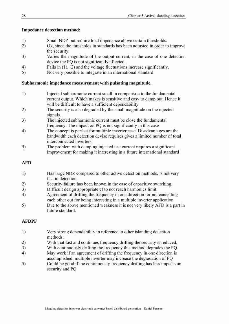
Impedance detection method: 1) Small NDZ but require load impedance above certain thresholds. 2) Ok, since the thresholds in standards has been adjusted in order to improve
the security. 3) Varies the magnitude of the output current, in the case of one detection
device the PQ is not significantly affected. 4) Fails in (1), (2) and the voltage fluctuations increase significantly. 5) Not very possible to integrate in an international standard Subharmonic impedance measurement with pulsating magnitude. 1) Injected subharmonic current small in comparison to the fundamental
current output. Which makes is sensitive and easy to damp out. Hence it will be difficult to have a sufficient dependability
2) The security is also degraded by the small magnitude on the injected signals.
3) The injected subharmonic current must be close the fundamental frequency. The impact on PQ is not significantly in this case
4) The concept is perfect for multiple inverter case. Disadvantages are the bandwidth each detection devise requires gives a limited number of total interconnected inverters.
5) The problem with damping injected test current requires a significant improvement for making it interesting in a future international standard
AFD 1) Has large NDZ compared to other active detection methods, is not very
fast in detection. 2) Security failure has been known in the case of capacitive switching. 3) Difficult design appropriate cf to not reach harmonics limit. 4) Agreement of drifting the frequency in one direction for not cancelling
each other out for being interesting in a multiple inverter application 5) Due to the above mentioned weakness it is not very likely AFD is a part in
future standard. AFDPF 1) Very strong dependability in reference to other islanding detection
methods. 2) With that fast and continues frequency drifting the security is reduced. 3) With continuously drifting the frequency this method degrades the PQ. 4) May work if an agreement of drifting the frequency in one direction is
accomplished, multiple inverter may increase the degradation of PQ 5) Could be good if the continuously frequency drifting has less impacts on
security and PQ
Chapter 5 Active islanding detection 29
Islanding detection in power electronic converter based distributed generation - Daniel Persson
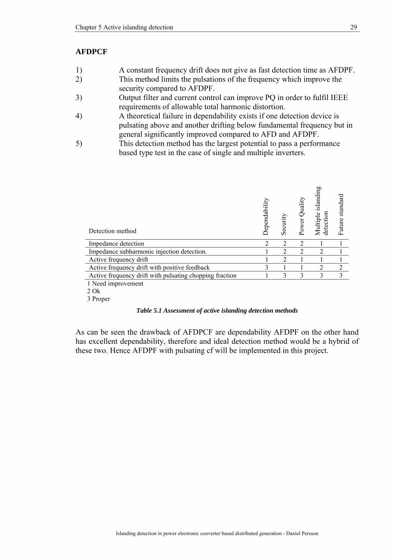
AFDPCF 1) A constant frequency drift does not give as fast detection time as AFDPF. 2) This method limits the pulsations of the frequency which improve the
security compared to AFDPF. 3) Output filter and current control can improve PQ in order to fulfil IEEE
requirements of allowable total harmonic distortion. 4) A theoretical failure in dependability exists if one detection device is
pulsating above and another drifting below fundamental frequency but in general significantly improved compared to AFD and AFDPF.
5) This detection method has the largest potential to pass a performance based type test in the case of single and multiple inverters.
Detection method
Dep
enda
bilit
y
Secu
rity
Pow
er Q
ualit
y
Mul
tiple
isla
ndin
g de
tect
ion
Futu
re st
anda
rd
Impedance detection 2 2 2 1 1 Impedance subharmonic injection detection. 1 2 2 2 1 Active frequency drift 1 2 1 1 1 Active frequency drift with positive feedback 3 1 1 2 2 Active frequency drift with pulsating chopping fraction 1 3 3 3 3
1 Need improvement 2 Ok 3 Proper
Table 5.1 Assessment of active islanding detection methods
As can be seen the drawback of AFDPCF are dependability AFDPF on the other hand has excellent dependability, therefore and ideal detection method would be a hybrid of these two. Hence AFDPF with pulsating cf will be implemented in this project.

31
Chapter 6
Simulation model In order to assess the selected detection method, a model of a LV distribution network has been implemented in the simulation program Matlab Simulink employing the toolbox SimPowerSystems. To achieve similar performance and behaviour of the power system as in reality, real data of the grid and its devices has been provided from utility company EON Elnät Sweden AB, micro turbine developer Turbec R&D and manufacturer of motors ABB LV Motors (Sweden) (see Appendix B for restrictions concerning the data). Inspiration and ideas for the active islanding detection has been gained from [12], [17].
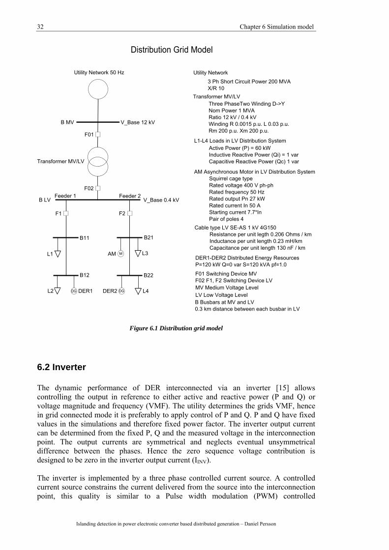
6.1 Distribution network A representative LV distribution network (Figure 6.1) has been implemented in Matlab Simulink. The base voltage in three phases has been determined to 12 kV and 0.4 kV at the MV and LV level. A fundamental frequency of 50 Hz is utilized. Further the utility short circuit power is determined 200 MVA and transformer nominal power 1 MVA. The LV cable has a rating of 1 kV and the LV feeder a total length of 0.6 km with 0.3 km distance between each LV bus. The LV grid contains two feeders, the background of this is applying two DER. This will be further discussed in Chapter 7.1 Case Studies. The load power consumption is determined to 60 kW in reference to DER output power, 120 kW at pf 1.0, due to the fact that a load following situation for μCHP is preferably (two loads in the feeder). It has been verified that the dynamic performance of the system is properly with the applied data.
32 Chapter 6 Simulation model
Islanding detection in power electronic converter based distributed generation – Daniel Persson
Figure 6.1 Distribution grid model
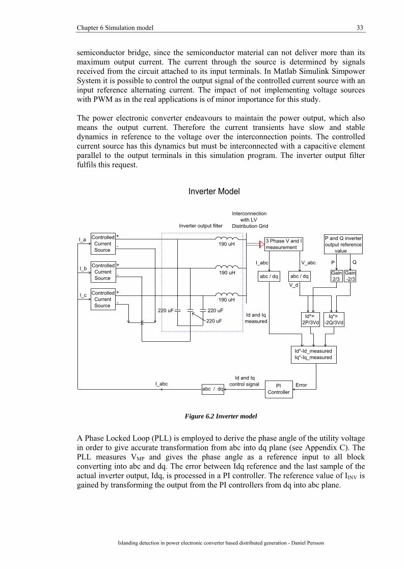
6.2 Inverter The dynamic performance of DER interconnected via an inverter [15] allows controlling the output in reference to either active and reactive power (P and Q) or voltage magnitude and frequency (VMF). The utility determines the grids VMF, hence in grid connected mode it is preferably to apply control of P and Q. P and Q have fixed values in the simulations and therefore fixed power factor. The inverter output current can be determined from the fixed P, Q and the measured voltage in the interconnection point. The output currents are symmetrical and neglects eventual unsymmetrical difference between the phases. Hence the zero sequence voltage contribution is designed to be zero in the inverter output current (IINV). The inverter is implemented by a three phase controlled current source. A controlled current source constrains the current delivered from the source into the interconnection point, this quality is similar to a Pulse width modulation (PWM) controlled
Chapter 6 Simulation model 33
Islanding detection in power electronic converter based distributed generation - Daniel Persson
semiconductor bridge, since the semiconductor material can not deliver more than its maximum output current. The current through the source is determined by signals received from the circuit attached to its input terminals. In Matlab Simulink Simpower System it is possible to control the output signal of the controlled current source with an input reference alternating current. The impact of not implementing voltage sources with PWM as in the real applications is of minor importance for this study. The power electronic converter endeavours to maintain the power output, which also means the output current. Therefore the current transients have slow and stable dynamics in reference to the voltage over the interconnection points. The controlled current source has this dynamics but must be interconnected with a capacitive element parallel to the output terminals in this simulation program. The inverter output filter fulfils this request.
Figure 6.2 Inverter model
A Phase Locked Loop (PLL) is employed to derive the phase angle of the utility voltage in order to give accurate transformation from abc into dq plane (see Appendix C). The PLL measures VMP and gives the phase angle as a reference input to all block converting into abc and dq. The error between Idq reference and the last sample of the actual inverter output, Idq, is processed in a PI controller. The reference value of IINV is gained by transforming the output from the PI controllers from dq into abc plane.

34 Chapter 6 Simulation model
Islanding detection in power electronic converter based distributed generation – Daniel Persson
6.3 Active islanding detection The active islanding detection is implemented in the state previous transforming back the current into abc reference frame. The angular reference gained from the PLL is slightly perturbed from the original value when transforming from dq into abc frame. The perturbation is pulsed and its on_time is 40 % of a period of 0.5 s. A similar pulse pattern is proposed in [17] in order to fulfil the power quality requirements. The islanding detection is sampled with a period of 20 µs. The input to the active frequency block is the voltage waveform of phase A (Va), the frequency of VMP and the frequency of IINV. By multiplying the previous mentioned frequencies with a factor of 2π, w_v and w_i is gained in radian/second. (Figure 6.3).
Figure 6.3 Inverter with integrated frequency drift
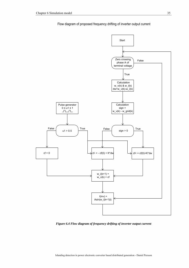
The flow chart of the algorithm is presented in Figure 6.4. The zero crossing detection of the voltage of phase A enables the measuring of w_v and w_i. A subtraction of the fundamental grid frequency and the voltage frequency, named sign in the flow chart, is calculated in order to determine which direction to drift the constant error cf0 (6.2). This improves the dependability by reducing the islanding detection time. Then the difference between the frequencies of VMP and IINV, dw, is derived. A suitable gain K amplifies dw in the same direction as sign and is added to the constant error cf0. The pulse generator determines at which time the perturbation should be added to the frequency of IINV (6.1). w_i(k+1) = w_v(k) + dw(k) (6.1) dw(k) = ±cf0 + K(w_v(k) - w_i(k)) (6.2)
Chapter 6 Simulation model 35
Islanding detection in power electronic converter based distributed generation - Daniel Persson
Figure 6.4 Flow diagram of frequency drifting of inverter output current

37
Chapter 7
Simulations
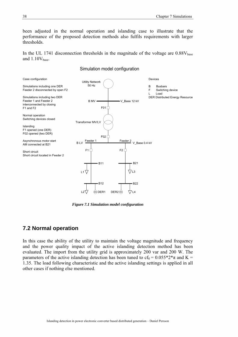
7.1 Case Studies In the simulation model presented in Figure 7.1 four cases are studied with one feeder interconnected with one DER and four cases with two feeders, each interconnected with one DER. Two active islanding detection in the same LV distribution system may have influence upon each other. All cases incorporate a load following scenario. This is accomplished by monitoring the export/import of active and reactive power from transformer LV busbar into the radial LV feeders and adjusting the loads so almost no power exchange occurs. All cases are studied at a transient state. Following cases have been analyzed:
Normal operation Verifying that the utility maintains the voltage magnitude and frequency stability when active islanding detection device operating. The PQ impacts of the perturbations are also studied.
Islanding
The dependability performance of the active islanding detection method is assessed in this case. The case of passive islanding detection asserts the need of active islanding detection.
Asynchronous motor start
The asynchronous (induction) motor draws a large current at the instant of the start which gives rise to a voltage sag. The contingency common and the security of the active islanding detection method is evaluated in this case.
Short circuit in LV distribution grid
The short circuit current causes a voltage drop. The security of protection will be assessed at two cases of short circuits.
In international standards over frequency (OF) and under frequency (UF) thresholds for disconnection of the DER from the utility grid are defined. From a manufacturer point of view it is important to adjust towards an international market, therefore the disconnection requirement from the UL 1741 and IEEE standard 1547 [2], [3] has been applied. In the European 50 Hz grid these limits are 49.3 and 50.5 Hz. Some European national standards have larger trip thresholds i.e. AMP (Swedish standard 48 and 51 Hz as UF and OF trip thresholds [7]). The parameters of the active islanding detection have
38 Chapter 7 Simulations
Islanding detection in power electronic converter based distributed generation – Daniel Persson
been adjusted in the normal operation and islanding case to illustrate that the performance of the proposed detection methods also fulfils requirements with larger thresholds. In the UL 1741 disconnection thresholds in the magnitude of the voltage are 0.88Vbase and 1.10Vbase.
Figure 7.1 Simulation model configuration
7.2 Normal operation In this case the ability of the utility to maintain the voltage magnitude and frequency and the power quality impact of the active islanding detection method has been evaluated. The import from the utility grid is approximately 200 var and 200 W. The parameters of the active islanding detection has been tuned to cf0 = 0.055*2*π and K = 1.35. The load following characteristic and the active islanding settings is applied in all other cases if nothing else mentioned.

Chapter 7 Simulations 39
Islanding detection in power electronic converter based distributed generation - Daniel Persson
7.2.1 Passive islanding detection This simulation include feeder 1 in Figure 7.1, freq Vmp is the frequency of the voltage over the output terminals of the DER, freq Iinv the frequency of the inverter output current, the difference between the previous mentioned frequencies in the third plot and cf is the perturbation in the output frequency. The current total harmonic distortion (THD) is measured at rated output current and refers to the power quality. As can be observed in the result (Figure 7.2) passive islanding detection does not have any impact on grid voltage and the current THD contribution is negligible.
0 0.1 0.2 0.3 0.449
49.5
50
50.5 freq V mp
Hz
0 0.1 0.2 0.3 0.449
49.5
50
50.5 freq I inv
Hz
0 0.1 0.2 0.3 0.4-0.2
-0.1
0
0.1
0.2 freq V mp - freq I inv
Hz
0 0.1 0.2 0.3 0.4-1
-0.5
0
0.5
1 cf
rad / s
0 0.1 0.2 0.3 0.40
1
2
3x 10
-3
THD
I h / I ph-n
Normal operation no active islanding detection
Figure 7.2 Normal operation passive isladning detection
7.2.2 Active islanding detection
As can be seen in Figure 7.3 the perturbation of the IINV frequency (freq I inv) caused by the active islanding detection does not have impacts on the VMP frequency (freq V mp). Important to notice is also the error between freq VMP and freq IINV determines the cf, which is related to the perturbation of freq IINV. The current THD contribution from the active islanding detection method with the above parameter settings measured at the maximum rated IINV (173 A rms) is around 0.25 %. This value is with settings with fast tripping during islanding condition. If the parameters are adjusted in order to trip closer 2 s the current THD contribution from the active islanding detection will decrease.

40 Chapter 7 Simulations
Islanding detection in power electronic converter based distributed generation – Daniel Persson
0 0.1 0.2 0.3 0.449
49.5
50
50.5 freq V mp
Hz
0 0.1 0.2 0.3 0.449
49.5
50
50.5 freq I inv
Hz
0 0.1 0.2 0.3 0.4-0.2
-0.1
0
0.1
0.2 freq V mp - freq I inv
Hz
0 0.1 0.2 0.3 0.4-1
-0.5
0
0.5
1 cf
rad / s
0 0.1 0.2 0.3 0.40
1
2
3x 10
-3 THD
I h / I ph-n
Normal operation active islanding detection
Figure 7.3 Normal operation active islanding detection, the duration of the perturbation is 0.1-0.3 s
7.2.3 Two DER active islanding detection
In the configuration where two DER are interconnected in the distribution grid the utility maintains the voltage magnitude and frequency. The drifting of frequency is the same for both DER and the current THD for each is equal the value measured in Figure 7.3.
0 0.05 0.1 0.15 0.2 0.25 0.3 0.35 0.4 0.45 0.549
49.5
50
50.5 freq V mp DER 1
Hz
0 0.05 0.1 0.15 0.2 0.25 0.3 0.35 0.4 0.45 0.549
49.5
50
50.5freq I inv DER 1
Hz
Normal operation 2 DER active islanding detection
Figure 7.4 Normal operation two DER active islanding detection
Chapter 7 Simulations 41
Islanding detection in power electronic converter based distributed generation - Daniel Persson
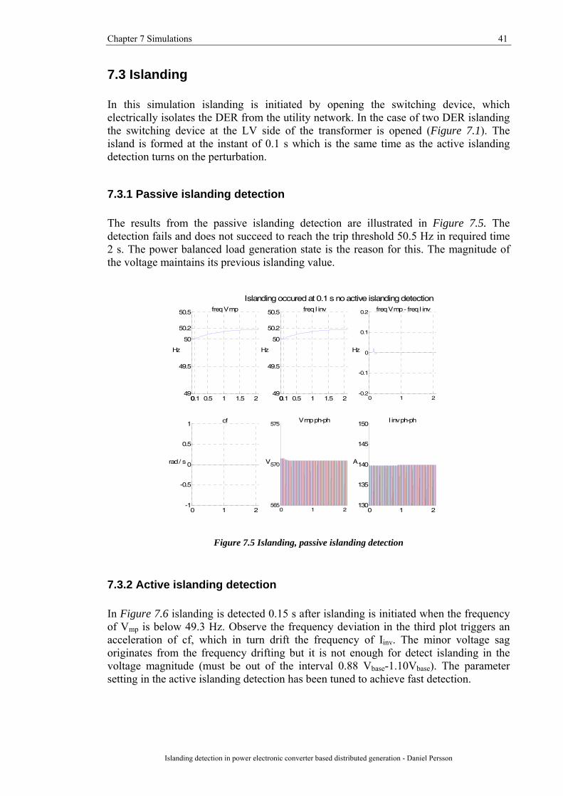
7.3 Islanding In this simulation islanding is initiated by opening the switching device, which electrically isolates the DER from the utility network. In the case of two DER islanding the switching device at the LV side of the transformer is opened (Figure 7.1). The island is formed at the instant of 0.1 s which is the same time as the active islanding detection turns on the perturbation.
7.3.1 Passive islanding detection The results from the passive islanding detection are illustrated in Figure 7.5. The detection fails and does not succeed to reach the trip threshold 50.5 Hz in required time 2 s. The power balanced load generation state is the reason for this. The magnitude of the voltage maintains its previous islanding value.
00.1 0.5 1 1.5 249
49.5
50
50.2
50.5 freq V mp
Hz
00.1 0.5 1 1.5 249
49.5
50
50.2
50.5 freq I inv
Hz
0 1 2-0.2
-0.1
0
0.1
0.2 freq V mp - freq I inv
Hz
0 1 2-1
-0.5
0
0.5
1 cf
rad / s
0 1 2565
570
575V mp ph-ph
V
0 1 2130
135
140
145
150I inv ph-ph
A
Islanding occured at 0.1 s no active islanding detection
Figure 7.5 Islanding, passive islanding detection
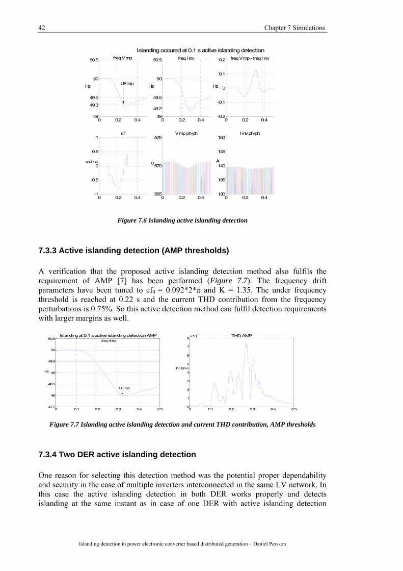
7.3.2 Active islanding detection In Figure 7.6 islanding is detected 0.15 s after islanding is initiated when the frequency of Vmp is below 49.3 Hz. Observe the frequency deviation in the third plot triggers an acceleration of cf, which in turn drift the frequency of Iinv. The minor voltage sag originates from the frequency drifting but it is not enough for detect islanding in the voltage magnitude (must be out of the interval 0.88 Vbase-1.10Vbase). The parameter setting in the active islanding detection has been tuned to achieve fast detection.
42 Chapter 7 Simulations
Islanding detection in power electronic converter based distributed generation – Daniel Persson
0 0.2 0.449
49.3
49.5
50
50.5 freq V mp
Hz
0 0.2 0.449
49.2
49.5
50
50.5 freq I inv
Hz
0 0.2 0.4-0.2
-0.1
0
0.1
0.2 freq V mp - freq I inv
Hz
0 0.2 0.4-1
-0.5
0
0.5
1cf
rad / s
0 0.2 0.4565
570
575V mp ph-ph
V
0 0.2 0.4130
135
140
145
150I inv ph-ph
A
Islanding occured at 0.1 s active islanding detection
UF trip
Figure 7.6 Islanding active islanding detection
7.3.3 Active islanding detection (AMP thresholds)
A verification that the proposed active islanding detection method also fulfils the requirement of AMP [7] has been performed (Figure 7.7). The frequency drift parameters have been tuned to cf0 = 0.092*2*π and K = 1.35. The under frequency threshold is reached at 0.22 s and the current THD contribution from the frequency perturbations is 0.75%. So this active detection method can fulfil detection requirements with larger margins as well.
0 0.1 0.2 0.3 0.4 0.547.5
48
48.5
49
49.5
50
50.5
Hz
freq Vmp
Islanding at 0.1 s active islanding detection AMP
UF trip
0 0.1 0.2 0.3 0.4 0.50
1
2
3
4
5
6
7
8x 10
-3 THD AMP
Ih / Iph-n
Figure 7.7 Islanding active islanding detection and current THD contribution, AMP thresholds
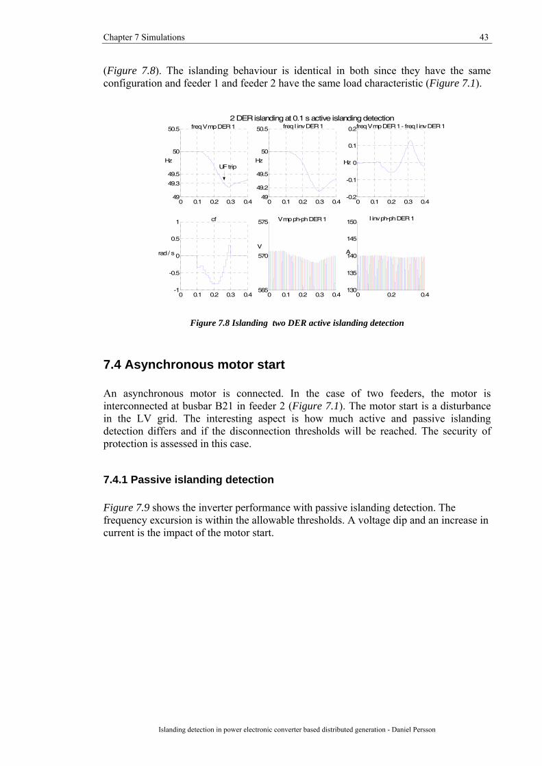
7.3.4 Two DER active islanding detection
One reason for selecting this detection method was the potential proper dependability and security in the case of multiple inverters interconnected in the same LV network. In this case the active islanding detection in both DER works properly and detects islanding at the same instant as in case of one DER with active islanding detection
Chapter 7 Simulations 43
Islanding detection in power electronic converter based distributed generation - Daniel Persson
(Figure 7.8). The islanding behaviour is identical in both since they have the same configuration and feeder 1 and feeder 2 have the same load characteristic (Figure 7.1).
0 0.1 0.2 0.3 0.449
49.3
49.5
50
50.5 freq V mp DER 1
Hz
0 0.1 0.2 0.3 0.449
49.2
49.5
50
50.5 freq I inv DER 1
Hz
0 0.1 0.2 0.3 0.4-0.2
-0.1
0
0.1
0.2freq V mp DER 1 - freq I inv DER 1
Hz
0 0.1 0.2 0.3 0.4-1
-0.5
0
0.5
1 cf
rad / s
0 0.1 0.2 0.3 0.4565
570
575 V mp ph-ph DER 1
V
0 0.2 0.4130
135
140
145
150I inv ph-ph DER 1
A
2 DER islanding at 0.1 s active islanding detection
UF trip
Figure 7.8 Islanding two DER active islanding detection
7.4 Asynchronous motor start An asynchronous motor is connected. In the case of two feeders, the motor is interconnected at busbar B21 in feeder 2 (Figure 7.1). The motor start is a disturbance in the LV grid. The interesting aspect is how much active and passive islanding detection differs and if the disconnection thresholds will be reached. The security of protection is assessed in this case.
7.4.1 Passive islanding detection Figure 7.9 shows the inverter performance with passive islanding detection. The frequency excursion is within the allowable thresholds. A voltage dip and an increase in current is the impact of the motor start.
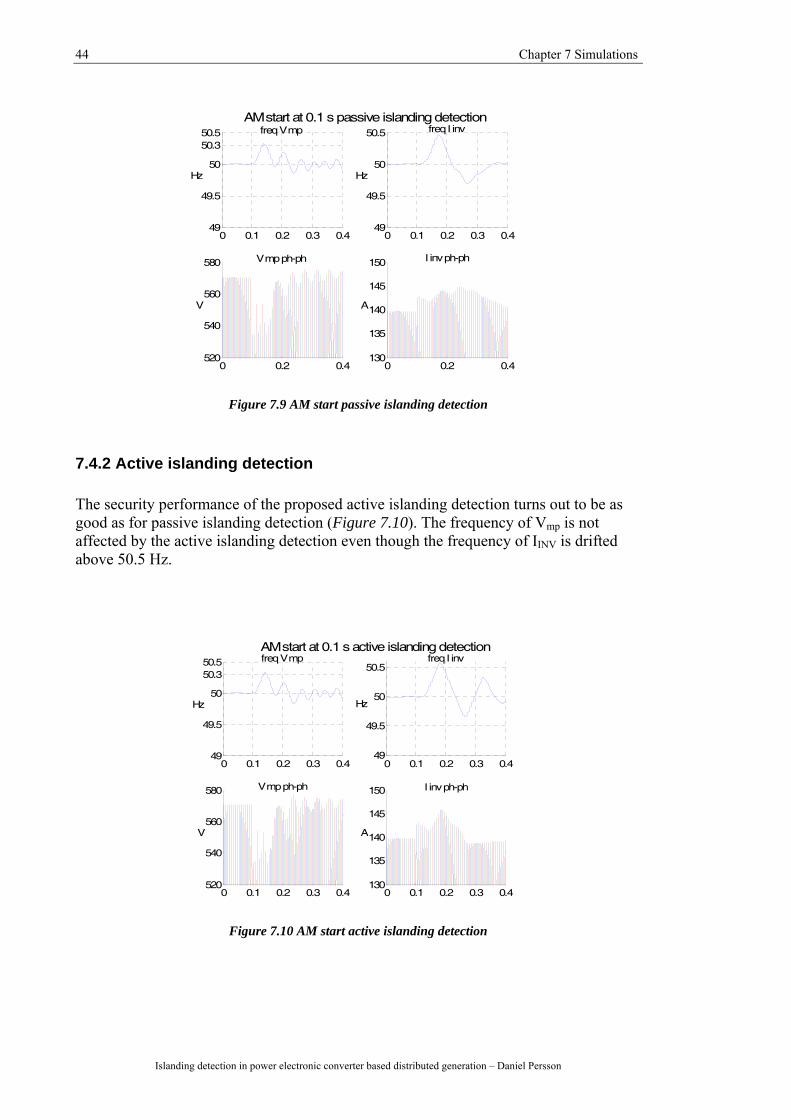
44 Chapter 7 Simulations
Islanding detection in power electronic converter based distributed generation – Daniel Persson
0 0.1 0.2 0.3 0.449
49.5
50
50.350.5 freq V mp
Hz
0 0.1 0.2 0.3 0.449
49.5
50
50.5 freq I inv
Hz
0 0.2 0.4520
540
560
580 V mp ph-ph
V
0 0.2 0.4130
135
140
145
150 I inv ph-ph
A
AM start at 0.1 s passive islanding detection
Figure 7.9 AM start passive islanding detection
7.4.2 Active islanding detection The security performance of the proposed active islanding detection turns out to be as good as for passive islanding detection (Figure 7.10). The frequency of Vmp is not affected by the active islanding detection even though the frequency of IINV is drifted above 50.5 Hz.
0 0.1 0.2 0.3 0.449
49.5
50
50.350.5 freq V mp
Hz
0 0.1 0.2 0.3 0.449
49.5
50
50.5freq I inv
Hz
0 0.1 0.2 0.3 0.4520
540
560
580 V mp ph-ph
V
0 0.1 0.2 0.3 0.4130
135
140
145
150 I inv ph-ph
A
AM start at 0.1 s active islanding detection
Figure 7.10 AM start active islanding detection

Chapter 7 Simulations 45
Islanding detection in power electronic converter based distributed generation - Daniel Persson
7.4.3 Two DER active islanding detection
This case involves two DER with active islanding detection operating in the LV distribution network and a motor starts in feeder 2. The DER operating in feeder 2 behaves similar as in the previous case without another feeder connected. This means that active islanding detection of DER 1 in adjacent feeder 1 does not have impact on the active islanding detection in DER 2 (Figure 7.11 & Figure 7.12).
0 0.1 0.2 0.3 0.449
49.5
50
50.3
50.5 freq V mp DER 2
Hz
0 0.1 0.2 0.3 0.449
49.5
50
50.5freq I inv DER 2
Hz
0 0.1 0.2 0.3 0.4-0.6
-0.4
-0.2
0
0.2
0.4
0.6freq V mp DER 2 - freq I inv DER 2
Hz
0 0.1 0.2 0.3 0.4-6
-4
-2
0
2
4
6 cf
rad / s
0 0.1 0.2 0.3 0.4520
540
560
580V mp ph-ph DER 2
V
0 0.1 0.2 0.3 0.4130
135
140
145
150 I inv ph-ph DER 2
A
2 DER AM start at 0.1 s active islanding detection
Figure 7.11 AM start two DER, motor interconnected in feeder 2
0 0.1 0.2 0.3 0.449
49.5
5050.1
50.5 freq V mp DER 1
Hz
0 0.1 0.2 0.3 0.449
49.5
50
50.5 freq I inv DER 1
Hz
0 0.1 0.2 0.3 0.4
-0.4
-0.2
0
0.2
0.4
0.6freq V mp DER 1 -freq I inv DER 1
Hz
0 0.1 0.2 0.3 0.4-6
-4
-2
0
2
4
6 cf
rad / s
0 0.1 0.2 0.3 0.4520
530
540
550
560
570
580 V mp ph-ph DER 1
V
0 0.1 0.2 0.3 0.4130
135
140
145
150 I inv ph-ph DER 1
A
2 DER AM start at 0.1s active islanding detection
Figure 7.12 AM start two DER, motor interconnected in feeder 2
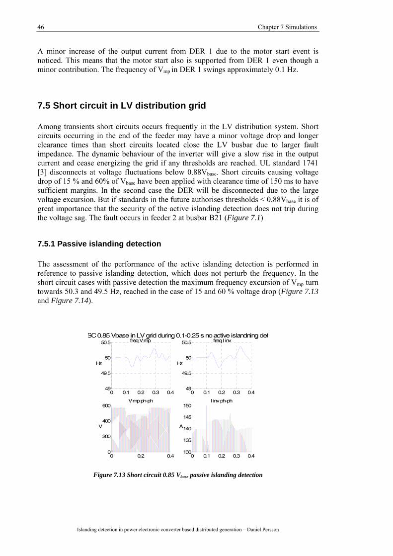
46 Chapter 7 Simulations
Islanding detection in power electronic converter based distributed generation – Daniel Persson
A minor increase of the output current from DER 1 due to the motor start event is noticed. This means that the motor start also is supported from DER 1 even though a minor contribution. The frequency of Vmp in DER 1 swings approximately 0.1 Hz.
7.5 Short circuit in LV distribution grid Among transients short circuits occurs frequently in the LV distribution system. Short circuits occurring in the end of the feeder may have a minor voltage drop and longer clearance times than short circuits located close the LV busbar due to larger fault impedance. The dynamic behaviour of the inverter will give a slow rise in the output current and cease energizing the grid if any thresholds are reached. UL standard 1741 [3] disconnects at voltage fluctuations below 0.88Vbase. Short circuits causing voltage drop of 15 % and 60% of Vbase have been applied with clearance time of 150 ms to have sufficient margins. In the second case the DER will be disconnected due to the large voltage excursion. But if standards in the future authorises thresholds < 0.88Vbase it is of great importance that the security of the active islanding detection does not trip during the voltage sag. The fault occurs in feeder 2 at busbar B21 (Figure 7.1)
7.5.1 Passive islanding detection The assessment of the performance of the active islanding detection is performed in reference to passive islanding detection, which does not perturb the frequency. In the short circuit cases with passive detection the maximum frequency excursion of Vmp turn towards 50.3 and 49.5 Hz, reached in the case of 15 and 60 % voltage drop (Figure 7.13 and Figure 7.14).
0 0.1 0.2 0.3 0.449
49.5
50
50.5 freq V mp
Hz
0 0.1 0.2 0.3 0.449
49.5
50
50.5 freq I inv
Hz
0 0.2 0.40
200
400
600V mp ph-ph
V
0 0.1 0.2 0.3 0.4130
135
140
145
150I inv ph-ph
A
SC 0.85 Vbase in LV grid during 0.1-0.25 s no active islandning det
Figure 7.13 Short circuit 0.85 Vbase passive islanding detection
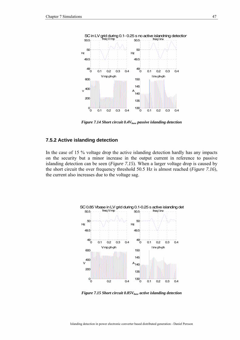
Chapter 7 Simulations 47
Islanding detection in power electronic converter based distributed generation - Daniel Persson
0 0.1 0.2 0.3 0.449
49.5
50
50.5 freq V mp
Hz
0 0.1 0.2 0.3 0.449
49.5
50
50.5 freq I inv
Hz
0 0.1 0.2 0.3 0.40
200
400
600V mp ph-ph
V
0 0.1 0.2 0.3 0.4130
135
140
145
150I inv ph-ph
A
SC in LV grid during 0.1- 0.25 s no active islandning detection
Figure 7.14 Short circuit 0.4Vbase passive islanding detection
7.5.2 Active islanding detection In the case of 15 % voltage drop the active islanding detection hardly has any impacts on the security but a minor increase in the output current in reference to passive islanding detection can be seen (Figure 7.15). When a larger voltage drop is caused by the short circuit the over frequency threshold 50.5 Hz is almost reached (Figure 7.16), the current also increases due to the voltage sag.
0 0.1 0.2 0.3 0.449
49.5
50
50.5 freq V mp
Hz
0 0.1 0.2 0.3 0.449
49.5
50
50.5 freq I inv
Hz
0 0.2 0.40
200
400
600V mp ph-ph
V
0 0.1 0.2 0.3 0.4130
135
140
145
150I inv ph-ph
A
SC 0.85 Vbase in LV grid during 0.1-0.25 s active islanding det
Figure 7.15 Short circuit 0.85Vbase active islanding detection
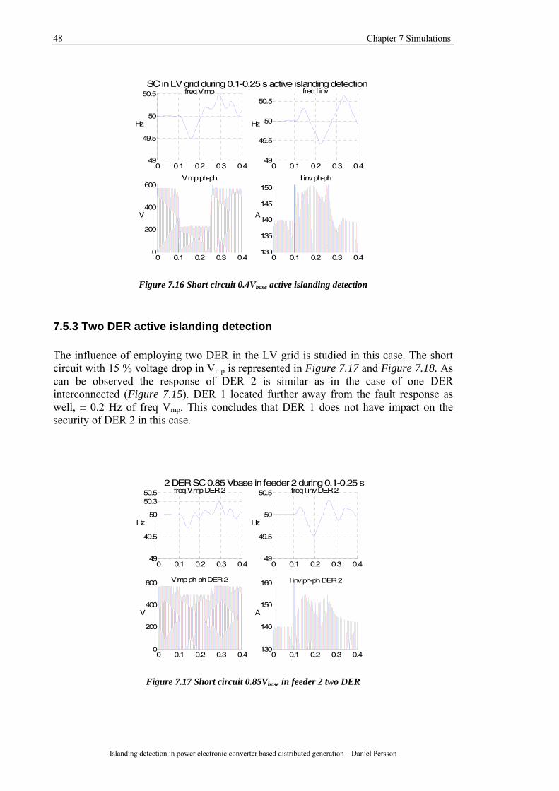
48 Chapter 7 Simulations
Islanding detection in power electronic converter based distributed generation – Daniel Persson
0 0.1 0.2 0.3 0.449
49.5
50
50.5 freq V mp
Hz
0 0.1 0.2 0.3 0.449
49.5
50
50.5
freq I inv
Hz
0 0.1 0.2 0.3 0.40
200
400
600V mp ph-ph
V
0 0.1 0.2 0.3 0.4130
135
140
145
150I inv ph-ph
A
SC in LV grid during 0.1-0.25 s active islanding detection
Figure 7.16 Short circuit 0.4Vbase active islanding detection
7.5.3 Two DER active islanding detection
The influence of employing two DER in the LV grid is studied in this case. The short circuit with 15 % voltage drop in Vmp is represented in Figure 7.17 and Figure 7.18. As can be observed the response of DER 2 is similar as in the case of one DER interconnected (Figure 7.15). DER 1 located further away from the fault response as well, ± 0.2 Hz of freq Vmp. This concludes that DER 1 does not have impact on the security of DER 2 in this case.
0 0.1 0.2 0.3 0.449
49.5
50
50.350.5 freq V mp DER 2
Hz
0 0.1 0.2 0.3 0.449
49.5
50
50.5 freq I inv DER 2
Hz
0 0.1 0.2 0.3 0.40
200
400
600 V mp ph-ph DER 2
V
0 0.1 0.2 0.3 0.4130
140
150
160 I inv ph-ph DER 2
A
2 DER SC 0.85 Vbase in feeder 2 during 0.1-0.25 s
Figure 7.17 Short circuit 0.85Vbase in feeder 2 two DER

Chapter 7 Simulations 49
Islanding detection in power electronic converter based distributed generation - Daniel Persson
0 0.1 0.2 0.3 0.449
49.5
5050.2
50.5 freq V mp DER 1
Hz
0 0.1 0.2 0.3 0.449
49.5
50
50.5 freq I inv DER 1
Hz
0 0.1 0.2 0.3 0.40
200
400
600 V mp ph-ph DER 1
V
0 0.2 0.4130
135
140
145
150 I inv ph-ph DER 1
A
2 DER SC 0.85 Vbase in feeder 2 during 0.1-0.25 s
Figure 7.18 Short circuit 0.85Vbase in feeder 2, two DER
The short circuit event causing 0.60Vbase voltage drop of over Vmp is equal the 0.15Vbase voltage drop concerning freq Vmp in DER 2 (Figure 7.17 and Figure 7.19). The frequency excursions are approximately ± 0.3 Hz. The current delivered from DER 2 into the grid is increased by 30 A during the 0.6Vbase voltage drop short circuit (Figure 7.19) which is more than during the short circuit causing 0.15Vbase voltage drop (Figure 7.17). DER 1 increases in frequency drifting against a value close ± 0.3 Hz, the same as DER 2. The voltage and current are not deviated as much as for DER 2, depending on the distance and that the utility grid is also supplying the short circuit from this direction. As previous mentioned the voltage relay will disconnect feeder 2 during an event like this but it is excellent that the security is robust enough to reject this disturbance.
0 0.1 0.2 0.3 0.449
49.5
50
50.350.5 freq V mp DER 2
Hz
0 0.1 0.2 0.3 0.449
49.5
50
50.5 freq I inv DER 2
Hz
0 0.1 0.2 0.3 0.40
200
400
600V mp ph-ph DER 2
V
0 0.1 0.2 0.3 0.4130
140
150
160
170
180I inv ph-ph DER 2
A
2 DER, SC in feeder 2 during 0.1-0.25 s
Figure 7.19 Short circuit 0.4Vbase in feeder 2, two DER

50 Chapter 7 Simulations
Islanding detection in power electronic converter based distributed generation – Daniel Persson
0 0.1 0.2 0.3 0.449
49.5
50
50.350.5 freq V mp DER 1
Hz
0 0.1 0.2 0.3 0.449
49.5
50
50.5 freq I inv DER 1
Hz
0 0.1 0.2 0.3 0.40
200
400
600 V mp ph-ph DER 1
V
0 0.1 0.2 0.3 0.4130
140
150
160
170
180 I inv ph-ph DER 1
A
2 DER SC feeder 2 during 0.1-0.25 s
Figure 7.20 Short circuit 0.4Vbase in feeder 2, two DER
The results from the short circuits illustrate a mal operation in the frequency of the inverter output current. The frequency increases even though the frequency of Vmp is decreasing and the active islanding detection contributes with a negative perturbation. The registered variation of frequency partly originates from a phase jump in Vmp (Figure 7.21). The PLL needs a time interval to measure the change in phase and therefore the mal operation of inverter output frequency.
0.085 0.09 0.095 0.1 0.105 0.11 0.115
-500
0
500V mp ph-ph DER 2
V
0.085 0.09 0.095 0.1 0.105 0.11 0.115
-200
0
200
I inv ph-ph DER 2
A
2 DER SC 0.85 V base feeder 2 during 0.1-0.25 s
Figure 7.21 Phase jump in voltage and current during short circuit
51
Chapter 8
Conclusions and recommendations
8.1 Introduction The report presents the research performed in this project. The main research questions were described in chapter 1: What require present European standards concerning unintentional islanding with distributed generation and what could be extended in future coming standards? What islanding detection methods have potential to fulfil future requirements with acceptable dependability and security? This chapter gives the findings of the project and recommendations for further research.
8.2 Research results
The European standards treating islanding detection have a wide variation in disconnection thresholds, cessation times and acceptable detection methods. Some International organisations (UL, IEEE and IEC) have performance based type test which includes detection of a power balanced load generation state in other words require active islanding detection. The test verifies only the dependability of protection (islanding detection capability), the security of protection (disturbance rejection) is not included. A revision of the standards in Germany and Austria towards more security and option of performance based islanding detection open doors for a European performance based islanding detection certification. Another important aspect is that previous required active islanding detection method (impedance) is not allowed in the case of installations with an AC output power ≥ 30 kW. A possible trend towards islanding detection with acceptable dependability and security in the case of larger output power and multiple inverters in the same low voltage network can be expected in the future. The performance based test opens doors for manufactures of DER to develop more dependable and secure islanding detection. The consumer would also obtain a DER
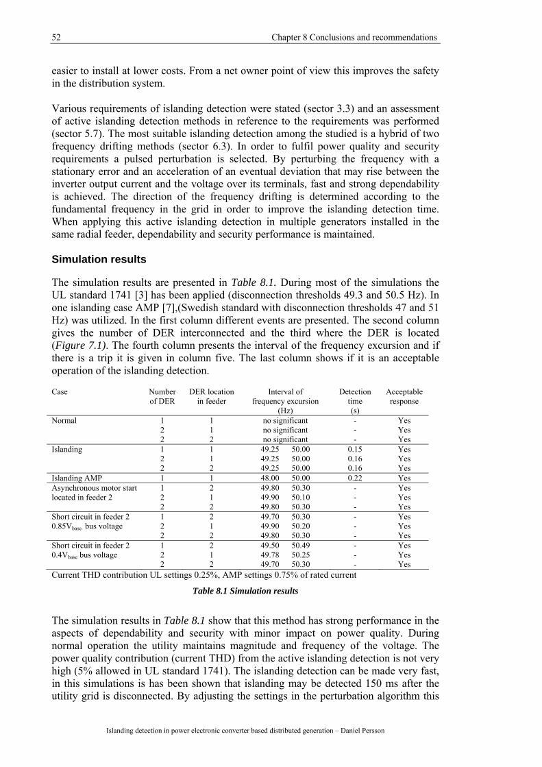
52 Chapter 8 Conclusions and recommendations
Islanding detection in power electronic converter based distributed generation – Daniel Persson
easier to install at lower costs. From a net owner point of view this improves the safety in the distribution system. Various requirements of islanding detection were stated (sector 3.3) and an assessment of active islanding detection methods in reference to the requirements was performed (sector 5.7). The most suitable islanding detection among the studied is a hybrid of two frequency drifting methods (sector 6.3). In order to fulfil power quality and security requirements a pulsed perturbation is selected. By perturbing the frequency with a stationary error and an acceleration of an eventual deviation that may rise between the inverter output current and the voltage over its terminals, fast and strong dependability is achieved. The direction of the frequency drifting is determined according to the fundamental frequency in the grid in order to improve the islanding detection time. When applying this active islanding detection in multiple generators installed in the same radial feeder, dependability and security performance is maintained. Simulation results The simulation results are presented in Table 8.1. During most of the simulations the UL standard 1741 [3] has been applied (disconnection thresholds 49.3 and 50.5 Hz). In one islanding case AMP [7],(Swedish standard with disconnection thresholds 47 and 51 Hz) was utilized. In the first column different events are presented. The second column gives the number of DER interconnected and the third where the DER is located (Figure 7.1). The fourth column presents the interval of the frequency excursion and if there is a trip it is given in column five. The last column shows if it is an acceptable operation of the islanding detection. Case Number
of DER DER location
in feeder Interval of
frequency excursion (Hz)
Detection time (s)
Acceptable response
Normal 1 1 no significant - Yes 2 1 no significant - Yes 2 2 no significant - Yes Islanding 1 1 49.25 50.00 0.15 Yes 2 1 49.25 50.00 0.16 Yes 2 2 49.25 50.00 0.16 Yes Islanding AMP 1 1 48.00 50.00 0.22 Yes Asynchronous motor start 1 2 49.80 50.30 - Yes located in feeder 2 2 1 49.90 50.10 - Yes 2 2 49.80 50.30 - Yes Short circuit in feeder 2 1 2 49.70 50.30 - Yes 0.85Vbase bus voltage 2 1 49.90 50.20 - Yes 2 2 49.80 50.30 - Yes Short circuit in feeder 2 1 2 49.50 50.49 - Yes 0.4Vbase bus voltage 2 1 49.78 50.25 - Yes 2 2 49.70 50.30 - Yes Current THD contribution UL settings 0.25%, AMP settings 0.75% of rated current
Table 8.1 Simulation results
The simulation results in Table 8.1 show that this method has strong performance in the aspects of dependability and security with minor impact on power quality. During normal operation the utility maintains magnitude and frequency of the voltage. The power quality contribution (current THD) from the active islanding detection is not very high (5% allowed in UL standard 1741). The islanding detection can be made very fast, in this simulations is has been shown that islanding may be detected 150 ms after the utility grid is disconnected. By adjusting the settings in the perturbation algorithm this
Chapter 8 Conclusions and recommendations for further research 53
Islanding detection in power electronic converter based distributed generation - Daniel Persson
active islanding detection has performance to fulfil standards which require other thresholds (AMP). The current THD value is though changed from 0.25% to 0.75% contribution. The dependability is proper also in the case of multiple DER installed. The security of protection also stays within acceptable ranges in the contingencies of an asynchronous motor start and short circuit in the low voltage distribution grid. In the extreme case of a short circuit causing 0.6Vbase voltage drop the islanding detection does not trip. Multiple inverters do not degrade the security of the active islanding detection in the simulated cases.
8.3 Recommendations for further research This report has evaluated what future standards may require in islanding detection performance and proposed an active islanding detection method that has the potential to fulfil those requirements. Still there are more steps to be taken towards safer distribution system with distributed generation.
The proposed active islanding detection method has shown good performance and this report is a perfect point of departure for an implementation in the software of real applications.
The expense for a manufacturer to upgrade the power electronic software with
this method includes software development and testing. Interesting aspects how new markets shares can be obtained by offering the customer safer products even though there is not a performance based requirement in European standards including active islanding detection year 2006. The long term profit for the manufacturer of working towards a safer distribution grid and sustainable society must also be considered.
Improving islanding detection is not the only aspect regarding safer distribution
system with distributed generation. In order to improve the capability of power supply, stand alone applications may be more common. A general problem is that power electronic converter based distributed generation does not contribute with larger short circuit currents. An evaluation treating requirements of short circuit performance of distributed generation would be suitable.
A Micro grid concept implies a cluster of loads and inverter based distributed
generation operating as a single controllable system (dispatchable from the utility) providing both heat and power to the local area. Each controllable energy source have an own controller using local information during utility parallel and micro grid operation. An Energy manager is the linkage between the utility and the micro grid determining individual set points in output power and bus voltage for each inverter. Wide research projects about micro grids would be of superior interests. The challenges are designing the energy manager, micro source controller and future standards. The concept must be economical feasible, how may governments encourage investments and what obstacles for realisation exists?

54 Chapter 8 Conclusions and recommendations
Islanding detection in power electronic converter based distributed generation – Daniel Persson
Automatic circuit reclosing may be employed in the switching devices between the utility grid and the low voltage grid. Applying both automatic circuit reslosing simultaneously as distributed generation is installed in the low voltage grid might be hazardous. The voltage magnitude, frequency and phase may fluctuate when the utility grid is disconnected and when the utility grid is re connected severe impacts may rise. Developing a strategy to make these systems compatible to each other would be a perfect future work that maintains the power supply performance simultaneously as distributed generation is integrated in the distribution system.
55
References Standards and Guidelines [1] IEEE Recommended Practise for Utility Interface of Photovoltaic (PV) Systems,
IEEE standard 929, 2000 [2] IEEE Standard for Interconnecting Distributed Resources with Electric Power
System, IEEE standard 1547, 2003 [3] Inverters, Converters, and controllers for Use in Independent Power Systems,
UL standard 1741, 2001 [4] Photovoltaic systems – characteristics of the utility interface, IEC international
standard 61727, 2004 [5] Requirements for the connection of micro generators in parallel with public low
voltage distribution network, CENELEC European standard, Draft prEN 50438, 2005
[6] Deliverable 1.1 + 1.2 Interconnection of Decentralised Energy Generation, A
Review of Standards, Technical Requirements and Procedures in the EU-15, ELEP, EIE/04/175/S07.38664, 2005
[7] AMP, Anslutning av mindre produktionsanläggningar till elnätet, Swedish
standard, Svensk energi, 1999 [8] Test procedure of islanding prevention measures for utility-interconnected
photovoltaic inverters, IEC international standard 62116, draft version, August 2006
[9] Selbstättige Schaltstelle zwischen einer netzparallelen Eigenerzeugungsanlage
und dem öffentlichen Niederspannungsnetz, German standard DIN VDE 0126-1-1, February 2006
[10] Power System Protection IEC Vocabulary, Chapter 448, IEC, 1995 [11] Kyoto protocol to the United Nations framework convention on climate change,
United Nations, 1997
56
Islanding detection in power electronic converter based distributed generation – Daniel Persson
Papers and Reports [12] IEA PVPS, Evaluation of islanding detection methods for photovoltaic utility-
interactive power systems, Report IEA PVPS T5-09:2002. www.iea.org. September 7, 2006
[13] SMA Regelsysteme Gmbh, ENS im Sunny Boy, Technische Beschreibung,
Ausgabe 1.1, 2000. http://download.sma-america.com/smaprosa/dateien/1348/SB-ENS-11-
ED4900.pdf. September 7, 2006 [14] R. Bründinger & B. Bletterie, “Unitentional islanding in distribution grids with a
high penetration of inverter based DG: Probability for islanding and protection methods”. Business Unit Renewable Energy Technologies, arsenal research, A-1030 Vienna, Austria. 2005
[15] R. Caldon, F. Rossetto & R. Turro, “Analysis of dynamic performance of
dispersed generation connected through inverter to distribution system”, CIRED 17th International conference on electricity distribution, Barcelona 12-15 May 2003
[16] F. Bertling & S. Soter, “A novel converter integrable impedance measuring
method for islanding detection in grids with widespread use of decentral generation”. Speedam (Symposium Power Electronics, Electrical Drives, Automation and Motion), 2006
[17] Y. Jung, G. Yu & J. Choi, “Novel AFD method with pulsation of chopping
fraction for islanding prevention of grid-connected photovoltaic inverter” EPE Dresden, 2005
[18] S. I. Jang & K. H. Kim, ”An islanding detection method for distributed
generation using voltage unbalance and total harmonic distortion”. IEEE Transactions on power delivery vol 19, No. 2, April 2004
[19] G. K. Hung, C. C. Chang & C. L. Chen, “Automatic phase shift method for
islanding detection of grid connected photovoltaic inverters”, IEEE Transactions on energy conversion, vol 18, No. 1, 1, March, 2003
[20] J. L. Duarte, An Introduction to Power Electronics as Applied to the
Interconnection of Sustainable Energy Systems to the Utility Grid. Department of Electrical Engineering, Eindhoven University of Technology, September 2003
57
Islanding detection in power electronic converter based distributed generation - Daniel Persson
Books [21] A. M. Borbely & J. F. Kreider, Distributed Generation The Power Paradigm for
the New Millenium. United States of America: CRC Press, 2001, ch 11 [22] N. Jenkins, A. Ron, P. Crossley, D. Kirschen, G. Strbac, “Embedded
Generation”. London, United Kingdom, The Institution of Electrical Engineers, 2000
[23] J. D. Glover & M. S. Sarna, Power System Analysis and Design 3rd edition.
United States of America: Brooks/Cole, 2002, ch 10 System protection [24] M. R. Patel, Wind and Solar Power Systems. United States of America: CRC
Press, 1999 Thesis reports [25] N. Stråth, Islanding in Power System, Licentiate Thesis. Department of
Industrial Electrical Engineering and Automation, Lund Institute of Technology, 2005
Manuals [26] Technical description T100 micro turbine system, March 2006 Class Notes [27] J.M.A. Myrzik, Distributed Generation: Class notes for 5N520, Department of
Electrical Engineering, Eindhoven University of Technology, 2006 Personal Communication [28] R. Greindl, PV-support Fronius (Austria), September 12 2006 [29] T. Göransson, Technical Manager, Turbec R&D (Sweden), September 25 2006


59
Appendix A
IEC 62116 Islanding detection test
List of case to be tested in IEC 62116 islanding detection test Case No. Condition
Inverter output power (%)
Inductive load reactance (%)
Deviation Pac (%)
Deviation Pqac (%)
1 A-UBL 100 100 -10 -10 2 A-UBL 100 100 -10 -5 3 A-UBL 100 100 -10 0 4 A-UBL 100 100 -10 5 5 A-UBL 100 100 -10 10 6 A-UBL 100 100 -5 -10 7 A-UBL 100 100 -5 -5 8 A-UBL 100 100 -5 0 9 A-UBL 100 100 -5 5
10 A-UBL 100 100 -5 10 11 A-UBL 100 100 0 -10 12 A-UBL 100 100 0 -5 13 A-BL 100 100 0 0 14 A-UBL 100 100 0 5 15 A-UBL 100 100 0 10 16 A-UBL 100 100 5 -10 17 A-UBL 100 100 5 -5 18 A-UBL 100 100 5 0 19 A-UBL 100 100 5 5 20 A-UBL 100 100 5 10 21 A-UBL 100 100 10 -10 22 A-UBL 100 100 10 -5 23 A-UBL 100 100 e 0 24 A-UBL 100 100 10 5
25 A-UBL 100 100 10 10
26 B-UBL 66 66 0 -5 27 B-UBL 66 66 0 -4 28 B-UBL 66 66 0 -3 29 B-UBL 66 66 0 -2 30 B-UBL 66 66 0 -1 31 B-BL 66 66 0 0 32 B-UBL 66 66 0 1 33 B-UBL 66 66 0 2 34 B-UBL 66 66 0 3 35 B-UBL 66 66 0 4
36 B-UBL 66 66 0 5
37 C-UBL 33 33 0 -5 38 C-UBL 33 33 0 -4
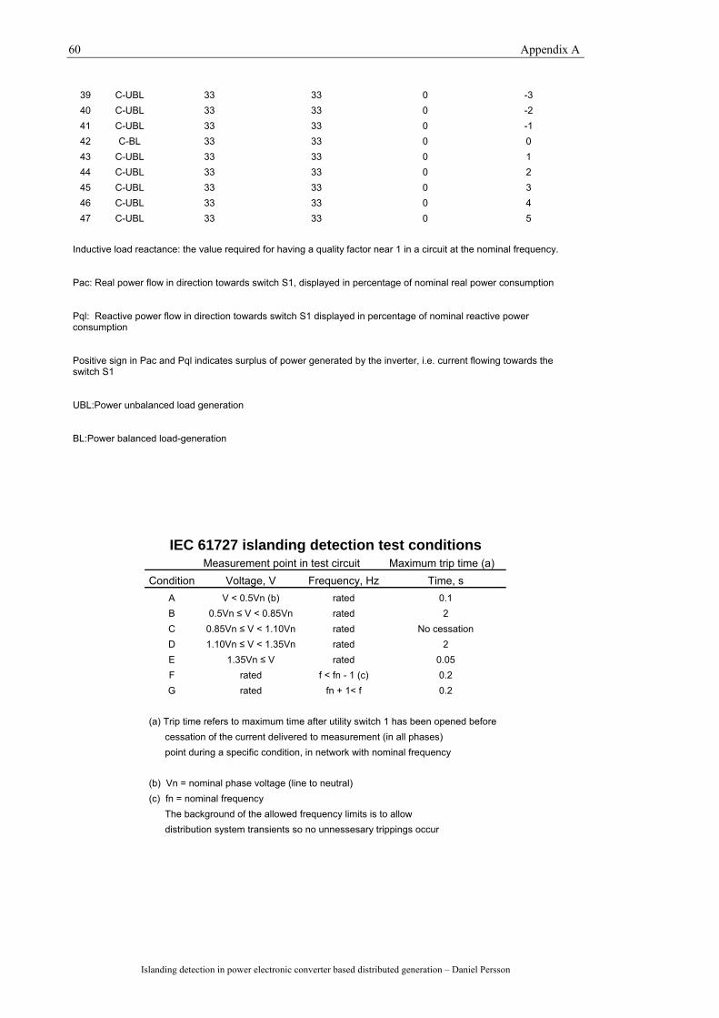
60 Appendix A
Islanding detection in power electronic converter based distributed generation – Daniel Persson
39 C-UBL 33 33 0 -3 40 C-UBL 33 33 0 -2 41 C-UBL 33 33 0 -1 42 C-BL 33 33 0 0 43 C-UBL 33 33 0 1 44 C-UBL 33 33 0 2 45 C-UBL 33 33 0 3 46 C-UBL 33 33 0 4 47 C-UBL 33 33 0 5
Inductive load reactance: the value required for having a quality factor near 1 in a circuit at the nominal frequency. Pac: Real power flow in direction towards switch S1, displayed in percentage of nominal real power consumption Pql: Reactive power flow in direction towards switch S1 displayed in percentage of nominal reactive power consumption Positive sign in Pac and Pql indicates surplus of power generated by the inverter, i.e. current flowing towards the switch S1 UBL:Power unbalanced load generation BL:Power balanced load-generation
IEC 61727 islanding detection test conditions Measurement point in test circuit Maximum trip time (a)
Condition Voltage, V Frequency, Hz Time, s A V < 0.5Vn (b) rated 0.1 B 0.5Vn ≤ V < 0.85Vn rated 2 C 0.85Vn ≤ V < 1.10Vn rated No cessation D 1.10Vn ≤ V < 1.35Vn rated 2 E 1.35Vn ≤ V rated 0.05 F rated f < fn - 1 (c) 0.2 G rated fn + 1< f 0.2
(a) Trip time refers to maximum time after utility switch 1 has been opened before cessation of the current delivered to measurement (in all phases) point during a specific condition, in network with nominal frequency (b) Vn = nominal phase voltage (line to neutral) (c) fn = nominal frequency The background of the allowed frequency limits is to allow distribution system transients so no unnessesary trippings occur
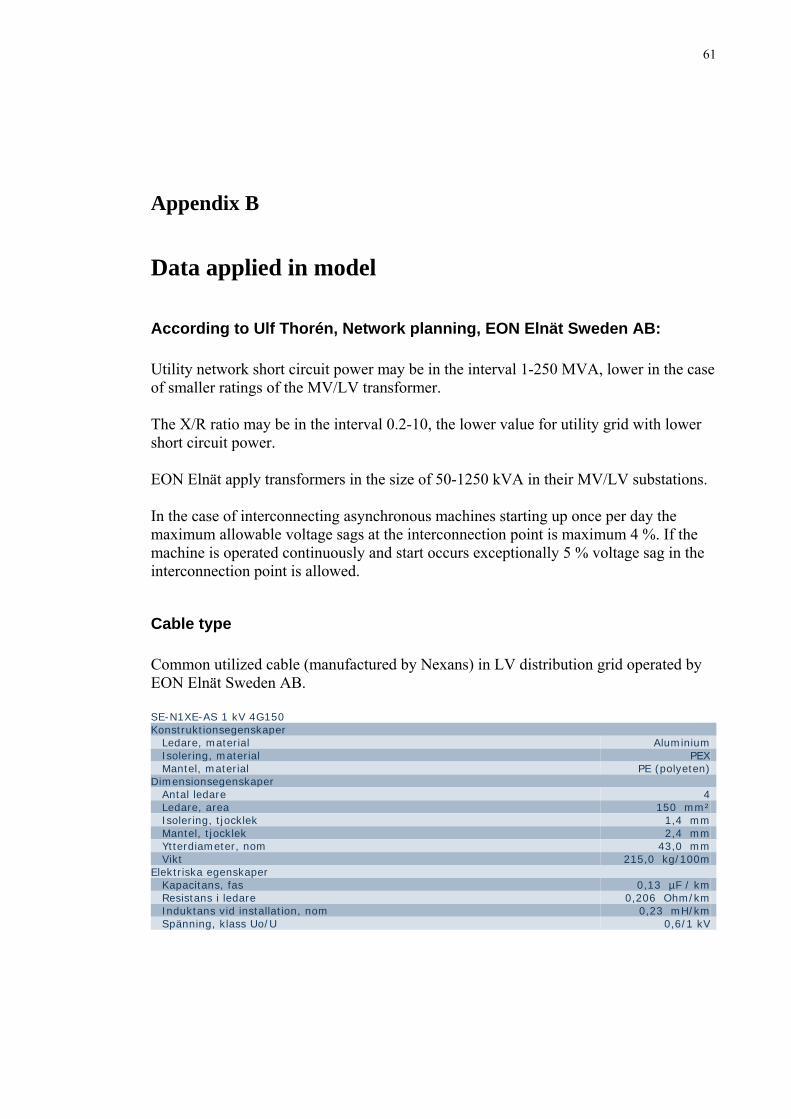
61
Appendix B
Data applied in model
According to Ulf Thorén, Network planning, EON Elnät Sweden AB: Utility network short circuit power may be in the interval 1-250 MVA, lower in the case of smaller ratings of the MV/LV transformer. The X/R ratio may be in the interval 0.2-10, the lower value for utility grid with lower short circuit power. EON Elnät apply transformers in the size of 50-1250 kVA in their MV/LV substations. In the case of interconnecting asynchronous machines starting up once per day the maximum allowable voltage sags at the interconnection point is maximum 4 %. If the machine is operated continuously and start occurs exceptionally 5 % voltage sag in the interconnection point is allowed.
Cable type Common utilized cable (manufactured by Nexans) in LV distribution grid operated by EON Elnät Sweden AB. SE-N1XE-AS 1 kV 4G150 Konstruktionsegenskaper Ledare, material Aluminium Isolering, material PEX Mantel, material PE (polyeten) Dimensionsegenskaper Antal ledare 4 Ledare, area 150 mm² Isolering, tjocklek 1,4 mm Mantel, tjocklek 2,4 mm Ytterdiameter, nom 43,0 mm Vikt 215,0 kg/100m Elektriska egenskaper Kapacitans, fas 0,13 µF / km Resistans i ledare 0,206 Ohm/km Induktans vid installation, nom 0,23 mH/km Spänning, klass Uo/U 0,6/1 kV
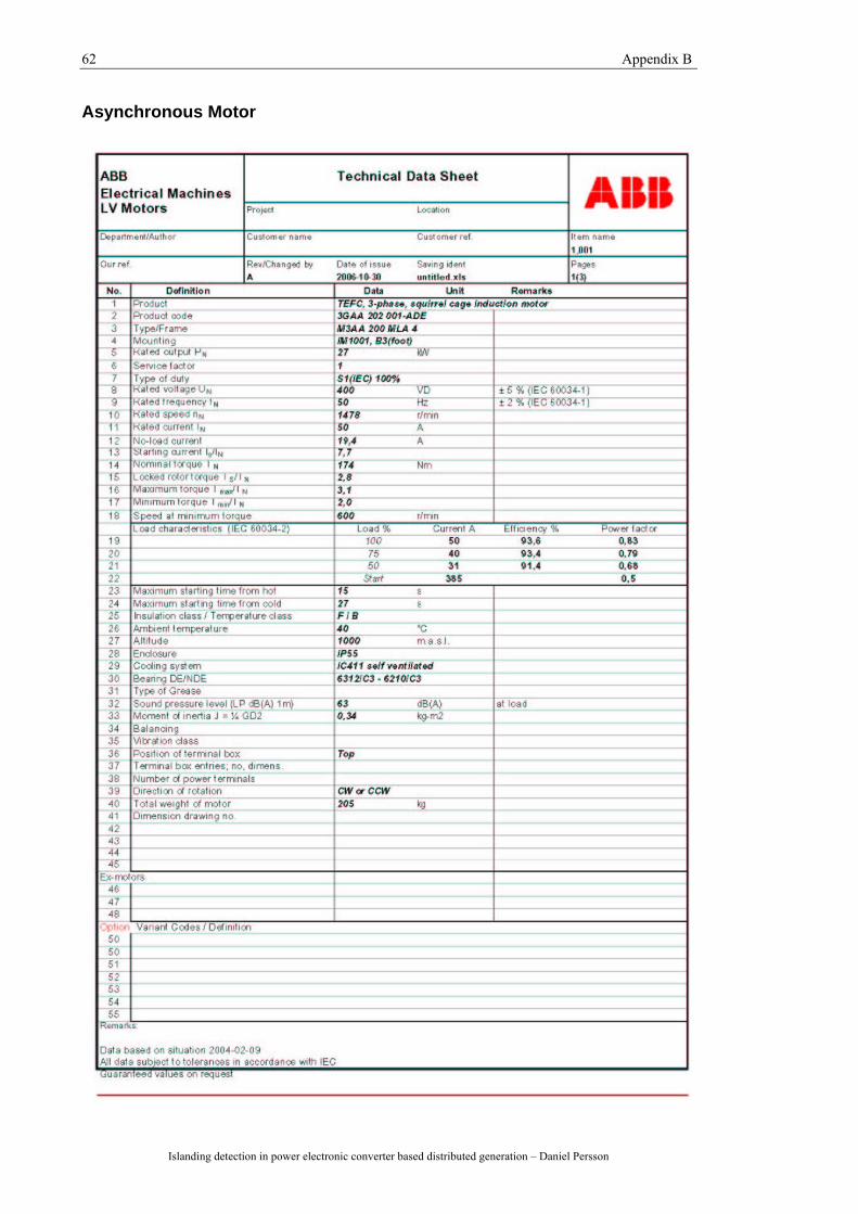
62 Appendix B
Islanding detection in power electronic converter based distributed generation – Daniel Persson
Asynchronous Motor
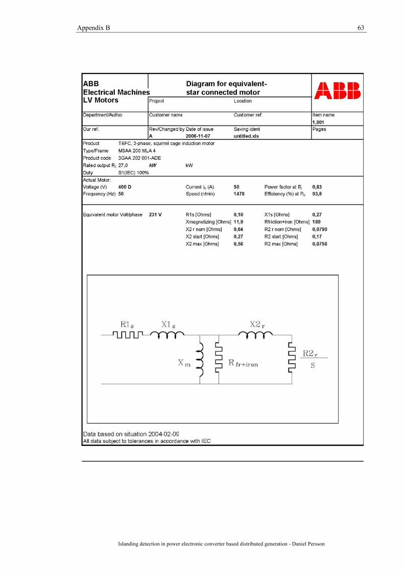
Appendix B 63
Islanding detection in power electronic converter based distributed generation - Daniel Persson
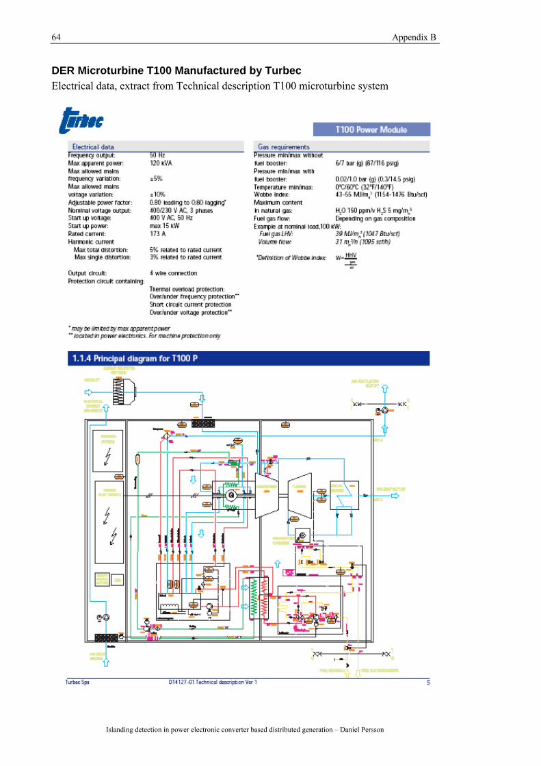
64 Appendix B
Islanding detection in power electronic converter based distributed generation – Daniel Persson
DER Microturbine T100 Manufactured by Turbec Electrical data, extract from Technical description T100 microturbine system
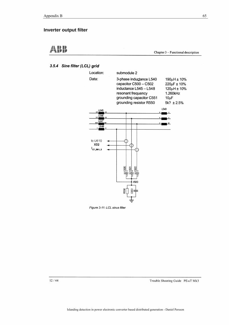
Appendix B 65
Islanding detection in power electronic converter based distributed generation - Daniel Persson
Inverter output filter

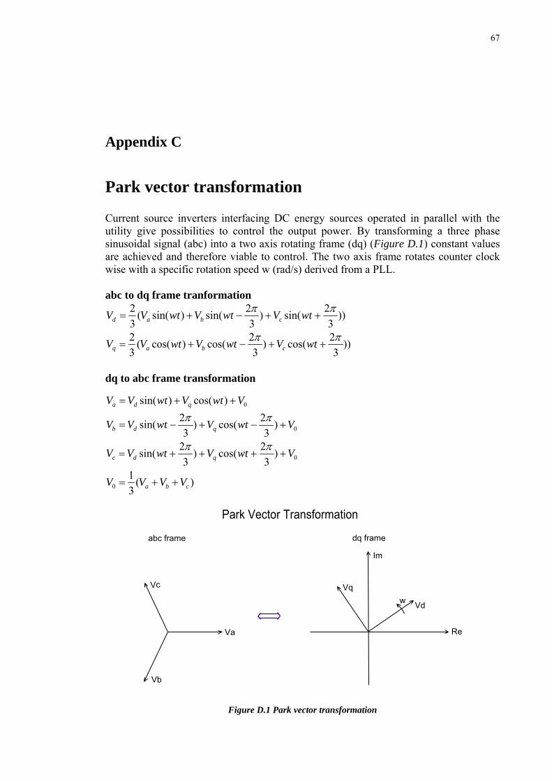
67
Appendix C
Park vector transformation Current source inverters interfacing DC energy sources operated in parallel with the utility give possibilities to control the output power. By transforming a three phase sinusoidal signal (abc) into a two axis rotating frame (dq) (Figure D.1) constant values are achieved and therefore viable to control. The two axis frame rotates counter clock wise with a specific rotation speed w (rad/s) derived from a PLL. abc to dq frame tranformation
))3
2sin()3
2sin()sin((32 ππ
++−+= wtVwtVwtVV cbad
))3
2cos()3
2cos()cos((32 ππ
++−+= wtVwtVwtVV cbaq
dq to abc frame transformation
0)cos()sin( VwtVwtVV qda ++=
0)3
2cos()3
2sin( VwtVwtVV qdb +−+−=ππ
0)3
2cos()3
2sin( VwtVwtVV qdc ++++=ππ
)(31
0 cba VVVV ++=
Figure D.1 Park vector transformation