Embed Size (px)
Citation preview

www.schiedel.com/uk
Isokern Pumice
SAP Issue 8 940002642 March 2019
System Chimneys & Liners
DON'T FORGET TO REGISTER YOUR INSTALLATIONSAND START EARNING SCHIEDEL INSTALLER REWARDSSee inside for more details
EARN SCHIEDEL INSTALLER REWARDS!
2
Pumice – naturally better
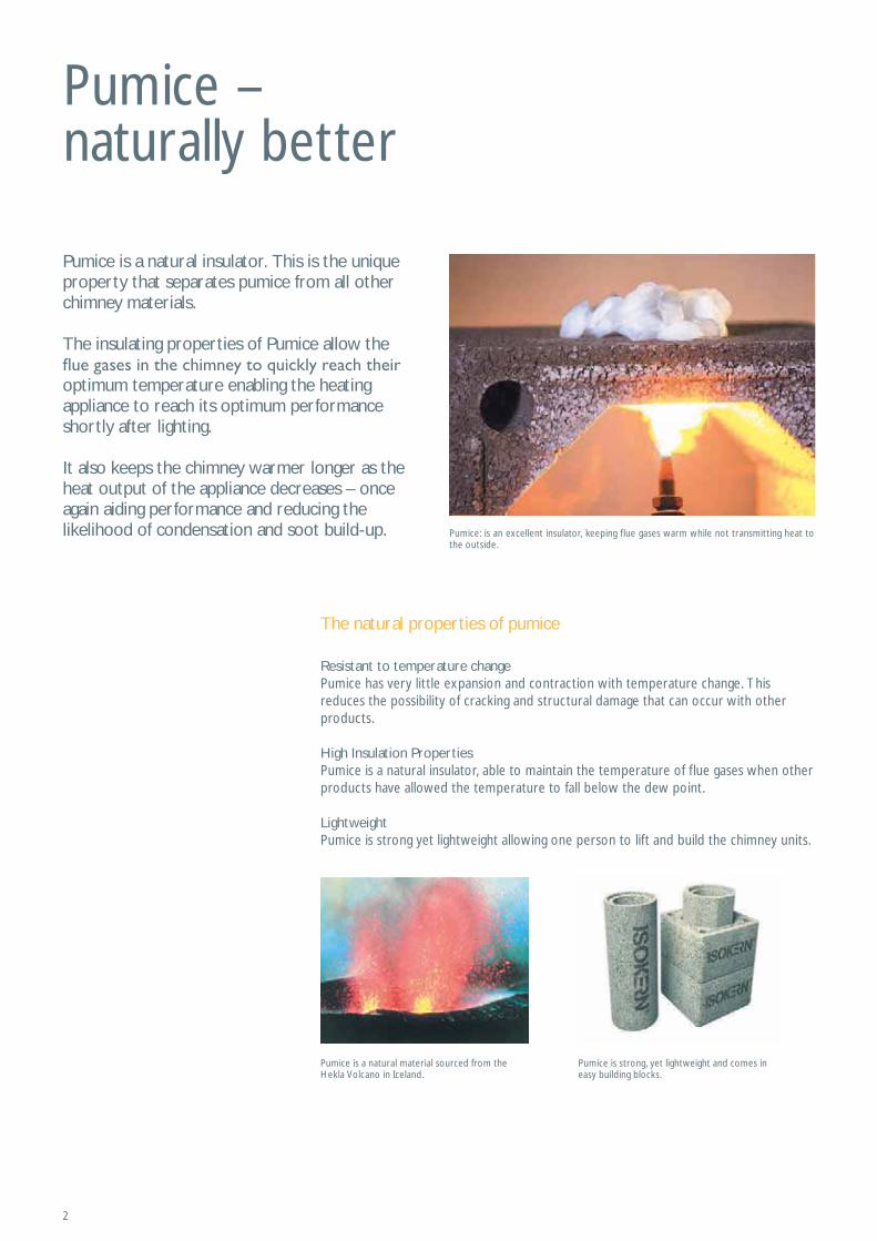
Pumice is a natural insulator. This is the unique property that separates pumice from all other chimney materials.
The insulating properties of Pumice allow the
optimum temperature enabling the heating appliance to reach its optimum performance shortly after lighting.
It also keeps the chimney warmer longer as the heat output of the appliance decreases – once again aiding performance and reducing the likelihood of condensation and soot build-up.
Resistant to temperature changePumice has very little expansion and contraction with temperature change. This reduces the possibility of cracking and structural damage that can occur with other products.
High Insulation PropertiesPumice is a natural insulator, able to maintain the temperature of flue gases when other products have allowed the temperature to fall below the dew point.
LightweightPumice is strong yet lightweight allowing one person to lift and build the chimney units.
The natural properties of pumice
Pumice is a natural material sourced from the Hekla Volcano in Iceland.
Pumice: is an excellent insulator, keeping flue gases warm while not transmitting heat to the outside.
Pumice is strong, yet lightweight and comes in easy building blocks.
3
Product Description
Schiedel Isokern products can be used for new chimneys and for the refurbishment of existing chimneys. The Isokern chimney systems provide a lightweight, easily installed and versatile chimney which can be used internally or externally.
The systems are suitable for use with burning appliances in new and refurbished projects. They are ideal for Masonry, Timber Frame and Steel Frame construction. Isokern chimneys have been installed in Europe for over 60 years.
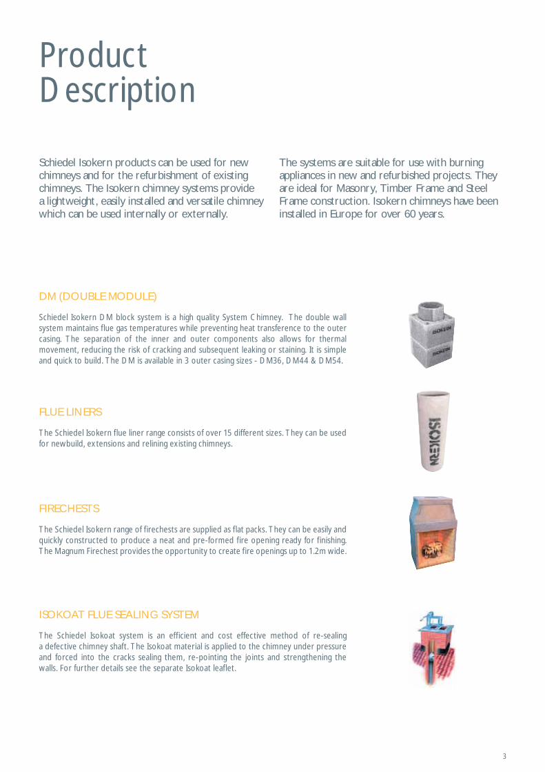
DM (DOUBLE MODULE)
FIRECHESTS
ISOKOAT FLUE SEALING SYSTEM
FLUE LINERS
Schiedel Isokern DM block system is a high quality System Chimney. The double wall system maintains flue gas temperatures while preventing heat transference to the outer casing. The separation of the inner and outer components also allows for thermal movement, reducing the risk of cracking and subsequent leaking or staining. It is simple and quick to build. The DM is available in 3 outer casing sizes - DM36, DM44 & DM54.
The Schiedel Isokern range of firechests are supplied as flat packs. They can be easily and quickly constructed to produce a neat and pre-formed fire opening ready for finishing. The Magnum Firechest provides the opportunity to create fire openings up to 1.2m wide.
The Schiedel Isokoat system is an efficient and cost effective method of re-sealing a defective chimney shaft. The Isokoat material is applied to the chimney under pressure and forced into the cracks sealing them, re-pointing the joints and strengthening the walls. For further details see the separate Isokoat leaflet.
The Schiedel Isokern flue liner range consists of over 15 different sizes. They can be used for newbuild, extensions and relining existing chimneys.

4
DM Double Module Chimney System
When the ease of construction and maximum insulation matter then the Double Module System comes into its own. The system is designed to be quick and easy to install.
The lightweight blocks are easy to handle. The outer and inner blocks are laid at the same time but with staggered joints for safety and stability. The double layer of pumice blocks separated by an air gap maximises the chimney insulation.
The Pumice Systems are suitable for wood burning, solid fuel, oil and gas (not condensing appliances including Biomass & Pellets).
There are 3 systems covering a range of different internal diameters to meet the requirements of different appliances and uses:
4
DM 36 150mm internal diameter for smaller output inserts, stoves and
solid fuel/oil cookers
DM 44180mm and 200mm internal diameters for inserts, stoves and
DM 54
55
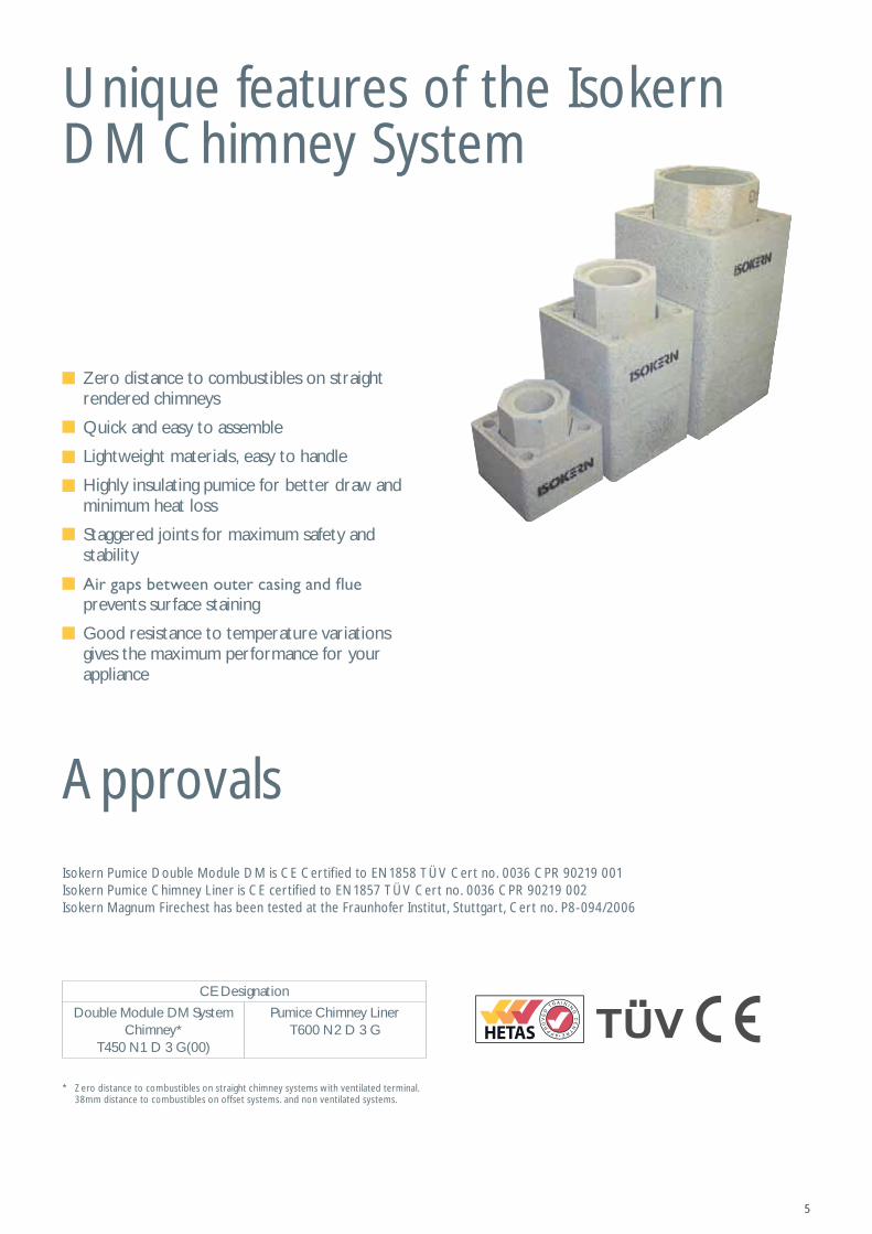
Unique features of the Isokern DM Chimney System
Zero distance to combustibles on straight rendered chimneys
Quick and easy to assemble
Lightweight materials, easy to handle
Highly insulating pumice for better draw and minimum heat loss
Staggered joints for maximum safety and stability
prevents surface staining
Good resistance to temperature variations gives the maximum performance for your appliance
ApprovalsIsokern Pumice Double Module DM is CE Certified to EN1858 TÜV Cert no. 0036 CPR 90219 001 Isokern Pumice Chimney Liner is CE certified to EN1857 TÜV Cert no. 0036 CPR 90219 002 Isokern Magnum Firechest has been tested at the Fraunhofer Institut, Stuttgart, Cert no. P8-094/2006
* Zero distance to combustibles on straight chimney systems with ventilated terminal. 38mm distance to combustibles on offset systems. and non ventilated systems.
CE Designation
Double Module DM System Chimney*
T450 N1 D 3 G(00)
Pumice Chimney LinerT600 N2 D 3 G
6
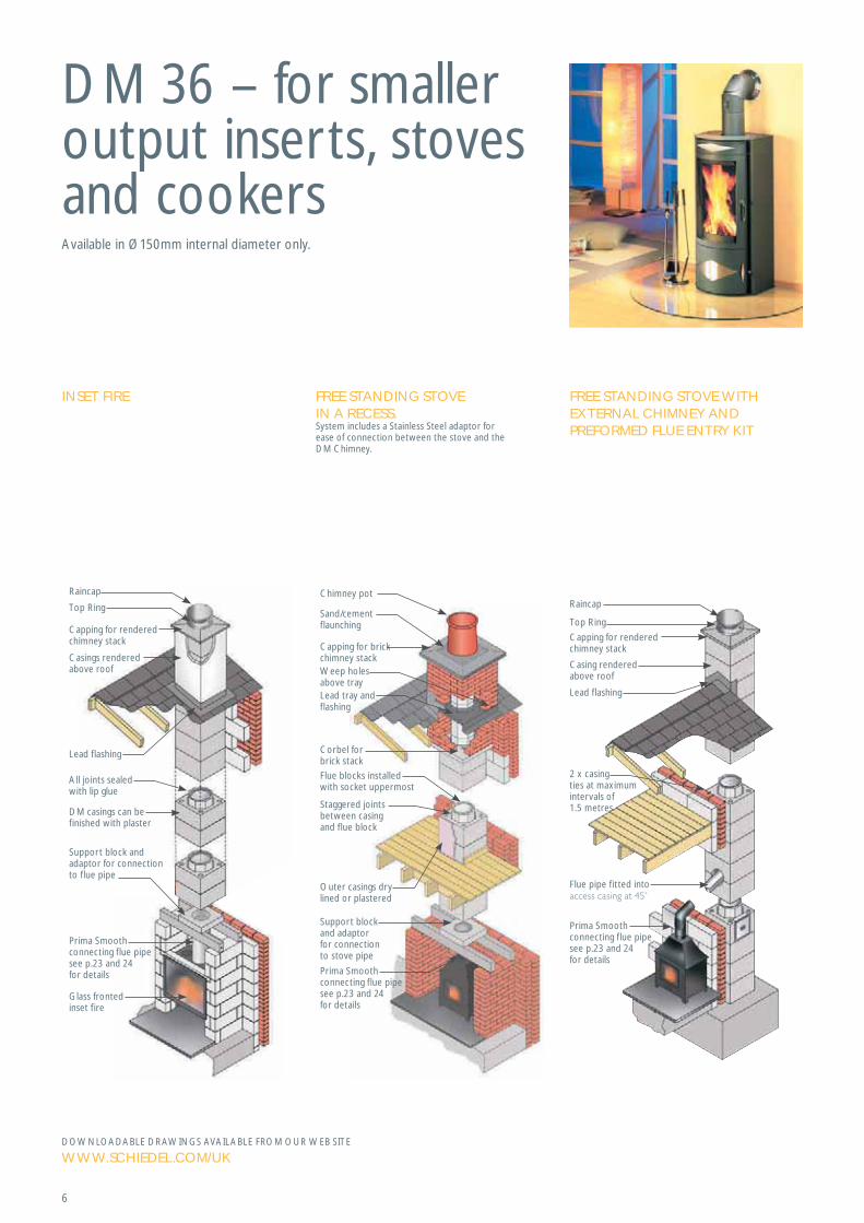
DM 36 – for smaller output inserts, stoves and cookersAvailable in Ø150mm internal diameter only.
DOWNLOADABLE DRAWINGS AVAILABLE FROM OUR WEB SITE
WWW.SCHIEDEL.COM/UK
INSET FIRE FREE STANDING STOVE IN A RECESS.System includes a Stainless Steel adaptor for ease of connection between the stove and the DM Chimney.
FREE STANDING STOVE WITH EXTERNAL CHIMNEY AND PREFORMED FLUE ENTRY KIT
Top Ring
Raincap
Capping for rendered chimney stack
2 x casing ties at maximum intervals of 1.5 metres
Flue pipe fitted into
Casing rendered above roof
Lead flashing
Prima Smoothconnecting flue pipe see p.23 and 24for details
Chimney pot
Capping for brick chimney stack
Corbel forbrick stack
Flue blocks installedwith socket uppermost
Staggered joints between casing and flue block
Support block and adaptor for connection to stove pipe
Outer casings dry lined or plastered
Lead tray and flashing
Weep holes above tray
Sand/cement flaunching
Prima Smoothconnecting flue pipe see p.23 and 24for details
Glass fronted inset f ire
Capping for renderedchimney stack
Casings renderedabove roof
Lead flashing
All joints sealedwith lip glue
DM casings can befinished with plaster
Top Ring
Raincap
Support block and adaptor for connection to flue pipe
Prima Smoothconnecting flue pipe see p.23 and 24for details
7
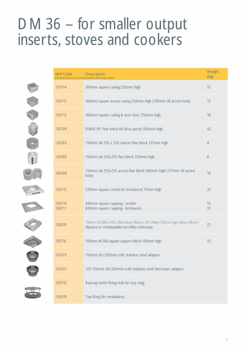
DM 36 – for smaller output inserts, stoves and cookers
SAP Code DescriptionWeight (kg)
130714 360mm square casing 250mm high 15
130712 360mm square access casing 250mm high (150mm i/d access hole) 13
130713 360mm square casing & soot door 250mm high 18
130709 DM36 45º flue entry kit (four parts) 500mm high 42
126363 150mm i/d 255 x 255 starter flue block 125mm high 4
126369 150mm i/d 255x255 flue block 250mm high 8
126368150mm i/d 255x255 access flue block 500mm high (177mm i/d access hole)
16
130715 570mm square corbel for brickwork 75mm high 32
130710130711
490mm square capping - render 690mm square capping - brickwork
1331
126378distance to combustibles on offset chimneys)
25
130716 150mm i/d 360 square support block 100mm high 15
126373 150mm i/d (205mm o/d) stainless steel adaptor
126357 125-150mm i/d (205mm o/d) stainless steel decreaser adaptor
130732 Raincap (with fixing rods for top ring)
135070 Top Ring (for ventilation)
All dimensions are external unless otherwise stated
8
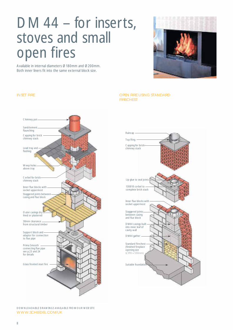
DM 44 – for inserts, stoves and small open firesAvailable in internal diameters Ø180mm and Ø200mm.Both inner liners fit into the same external block size.
DOWNLOADABLE DRAWINGS AVAILABLE FROM OUR WEB SITE
WWW.SCHIEDEL.COM/UK
OPEN FIRE USING STANDARD FIRECHEST
Lip glue to seal joints
130818 corbel to complete brick stack
Inner flue blocks withsocket uppermost
Staggered joints between casing and flue block
DM44 casings built into inner leaf of cavity wall
DM44 gather
Suitable foundation
Standard firechest(finished fireplace opening size
Capping for brickchimney stack
Top Ring
Raincap
Chimney pot
Weep holesabove tray
Capping for brickchimney stack
Sand/cement flaunching
Lead tray and flashing
Corbel for brick chimney stack
Inner flue blocks withsocket uppermost
Support block and adaptor for connection to flue pipe
Glass fronted inset f ire
Staggered joints between casing and flue block
38mm clearancefrom structural timber
Outer casings dry lined or plastered
Prima Smoothconnecting flue pipe see p.23 and 24for details
INSET FIRE
9
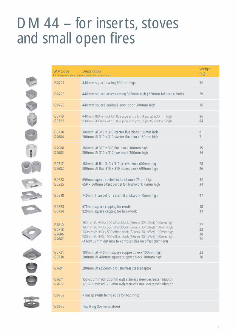
DM 44 – for inserts, stoves and small open fires
SAP Code DescriptionWeight (kg)
130727 440mm square casing 300mm high 30
130725 440mm square access casing 300mm high (220mm i/d access hole) 29
130726 440mm square casing & soot door 300mm high 36
130719130722
8684
130720127684
180mm i/d 310 x 310 starter flue block 150mm high200mm i/d 310 x 310 starter flue block 150mm high
87
127068127683
180mm i/d 310 x 310 flue block 300mm high200mm i/d 310 x 310 flue block 300mm high
1514
130717127682
180mm i/d flue 310 x 310 access block 600mm high200mm i/d flue 310 x 310 access block 600mm high
2826
130728130235
650mm square corbel for brickwork 75mm high650 x 560mm offset corbel for brickwork 75mm high
4034
130818 740mm T corbel for external brickwork 75mm high 47
130723130724
570mm square capping for render820mm square capping for brickwork
1844
131810130718127686127687
(Allow 38mm distance to combustibles on offset chimneys)
22322030
130721130730
180mm i/d 440mm square support block 100mm high 200mm i/d 440mm square support block 100mm high
2220
127691 200mm i/d (255mm o/d) stainless steel adaptor
127671127672
150-200mm i/d (255mm o/d) stainless steel decreaser adaptor175-200mm i/d (255mm o/d) stainless steel decreaser adaptor
130732 Raincap (with fixing rods for top ring)
130675 Top Ring (for ventilation)
All dimensions are external unless otherwise stated
10
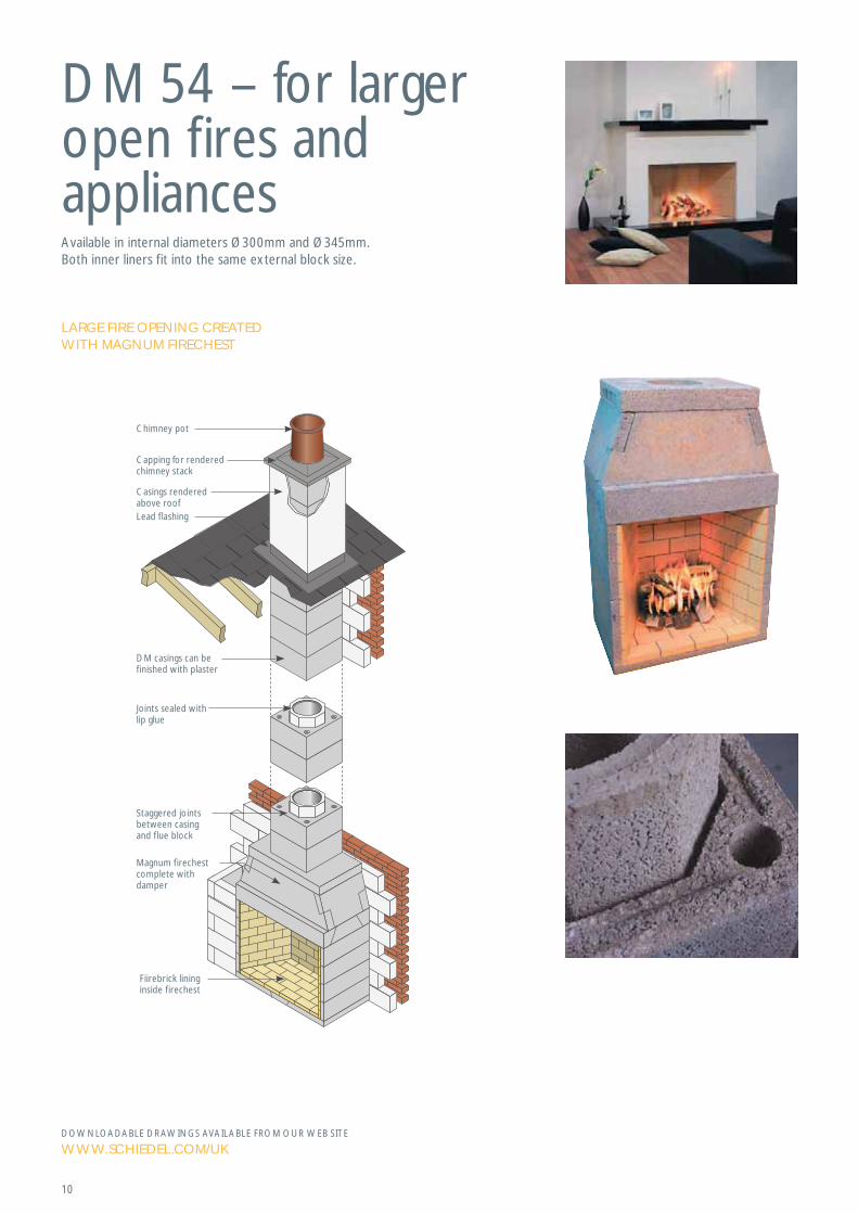
DM 54 – for larger open fires and appliancesAvailable in internal diameters Ø300mm and Ø345mm.Both inner liners fit into the same external block size.
DOWNLOADABLE DRAWINGS AVAILABLE FROM OUR WEB SITE
WWW.SCHIEDEL.COM/UK
LARGE FIRE OPENING CREATED WITH MAGNUM FIRECHEST
Staggered joints between casing and flue block
Magnum firechestcomplete with damper
Fiirebrick lininginside firechest
DM casings can befinished with plaster
Joints sealed with lip glue
Casings renderedabove roofLead flashing
Capping for rendered chimney stack
Chimney pot

11
DM 54 – for larger open fires and appliances
DM Accessories
SAP Code DescriptionWeight (kg)
130708 545mm square casing 300mm high 40
129031129093
300mm i/d 420 x 420 starter flue block 150mm high345mm i/d 420 x 420 starter flue block 150mm high
1111
129033129094
300mm i/d 420 x 420 flue block 300mm high345mm i/d 420 x 420 flue block 300mm high
2222
130735 800mm square corbel for brickwork 75mm high 57
130733130734
670mm square capping for render 950mm square capping for brickwork
2046
129038129092
(allow 38mm distance to combustibles on offset chimneys)
4440
129043 00mm i/d 545mm square support block 100mm high 30
129043 300mm i/d (365mm o/d) stainless steel adaptor
130732 Raincap (with fixing rods for top ring)
135093 Top Ring (for ventilation)
SAP Code DescriptionWeight (kg)
146432 1500 x 215 x 70mm support lintel Max load (per pair) 1650kg 51
130689 Stainless steel casing wall tie
130771 Lip glue (5kg) 5
102629 1m reinforcement rod 12mm diameter 1
All dimensions are external unless otherwise stated
All dimensions are external unless otherwise stated
12
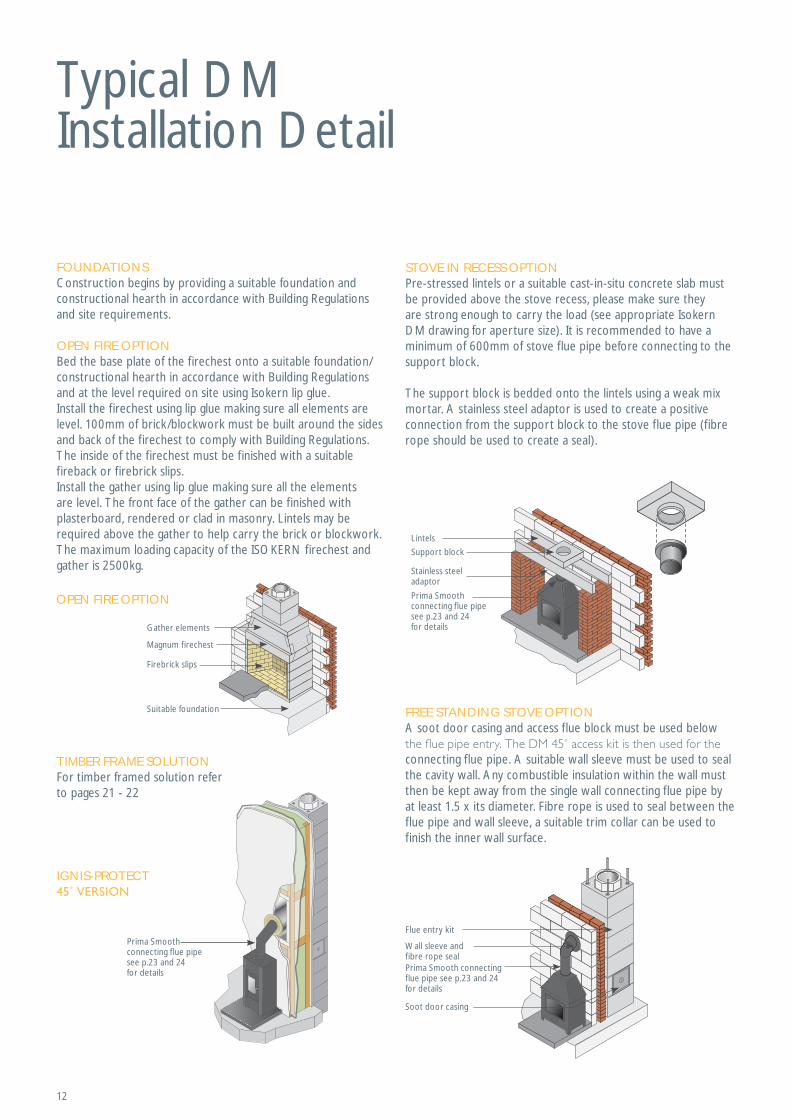
Typical DM Installation Detail
FOUNDATIONSConstruction begins by providing a suitable foundation and constructional hearth in accordance with Building Regulations and site requirements.
OPEN FIRE OPTIONBed the base plate of the firechest onto a suitable foundation/constructional hearth in accordance with Building Regulations and at the level required on site using Isokern lip glue.Install the firechest using lip glue making sure all elements are level. 100mm of brick/blockwork must be built around the sides and back of the firechest to comply with Building Regulations. The inside of the firechest must be finished with a suitable fireback or firebrick slips.Install the gather using lip glue making sure all the elements are level. The front face of the gather can be finished with plasterboard, rendered or clad in masonry. Lintels may be required above the gather to help carry the brick or blockwork. The maximum loading capacity of the ISOKERN firechest and gather is 2500kg.
TIMBER FRAME SOLUTIONFor timber framed solution refer to pages 21 - 22
STOVE IN RECESS OPTIONPre-stressed lintels or a suitable cast-in-situ concrete slab must be provided above the stove recess, please make sure they are strong enough to carry the load (see appropriate Isokern DM drawing for aperture size). It is recommended to have a minimum of 600mm of stove flue pipe before connecting to the support block.
The support block is bedded onto the lintels using a weak mix mortar. A stainless steel adaptor is used to create a positive connection from the support block to the stove flue pipe (fibre rope should be used to create a seal).
FREE STANDING STOVE OPTIONA soot door casing and access flue block must be used below
connecting flue pipe. A suitable wall sleeve must be used to seal the cavity wall. Any combustible insulation within the wall must then be kept away from the single wall connecting flue pipe by at least 1.5 x its diameter. Fibre rope is used to seal between the flue pipe and wall sleeve, a suitable trim collar can be used to finish the inner wall surface.
OPEN FIRE OPTION
Firebrick slips
Suitable foundation
Magnum firechest
Gather elements
IGNIS-PROTECT
Prima Smoothconnecting flue pipe see p.23 and 24for details
Flue entry kit
Wall sleeve andfibre rope seal
Soot door casing
Prima Smooth connecting flue pipe see p.23 and 24 for details
Support block
Lintels
Stainless steel adaptor
Prima Smoothconnecting flue pipe see p.23 and 24 for details
13
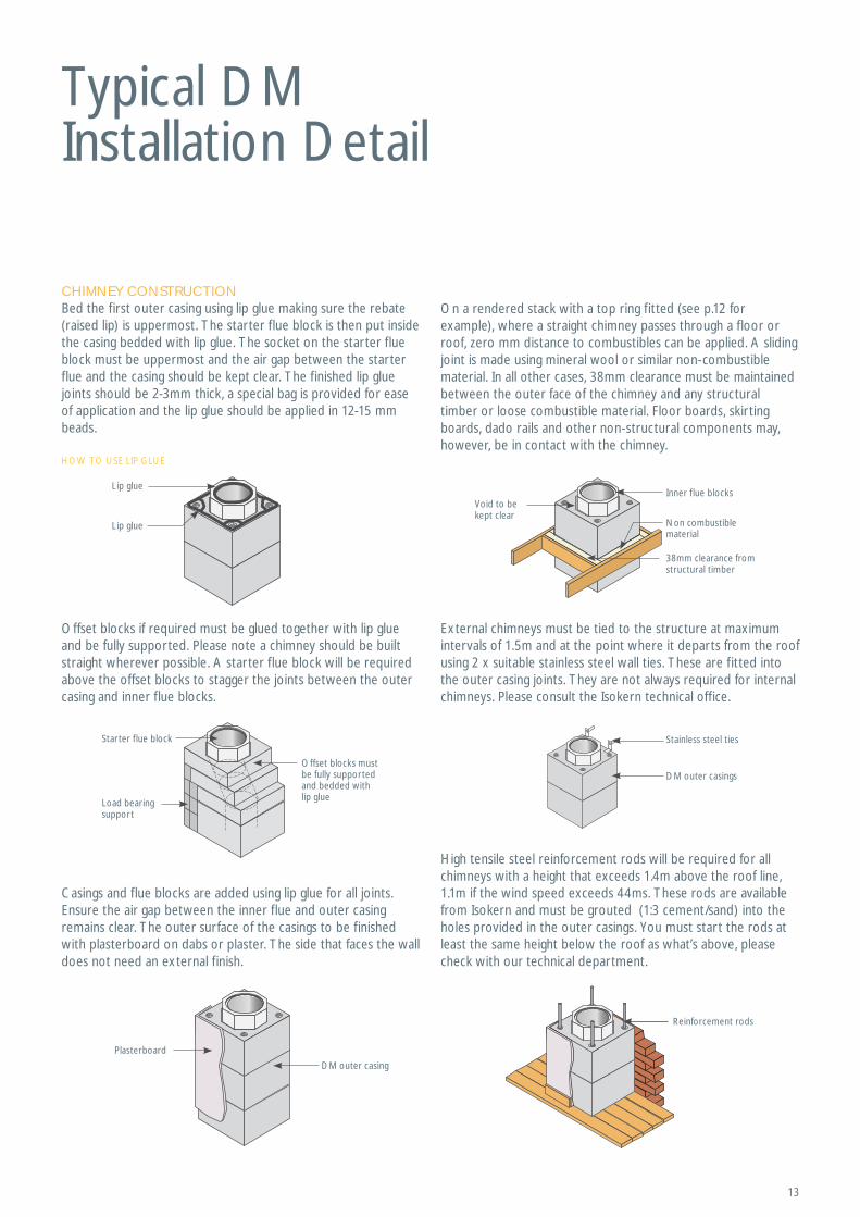
Typical DM Installation Detail
CHIMNEY CONSTRUCTIONBed the first outer casing using lip glue making sure the rebate (raised lip) is uppermost. The starter flue block is then put inside the casing bedded with lip glue. The socket on the starter flue block must be uppermost and the air gap between the starter flue and the casing should be kept clear. The finished lip glue joints should be 2-3mm thick, a special bag is provided for ease of application and the lip glue should be applied in 12-15 mm beads.
Offset blocks if required must be glued together with lip glue and be fully supported. Please note a chimney should be built straight wherever possible. A starter flue block will be required above the offset blocks to stagger the joints between the outer casing and inner flue blocks.
Casings and flue blocks are added using lip glue for all joints. Ensure the air gap between the inner flue and outer casing remains clear. The outer surface of the casings to be finished with plasterboard on dabs or plaster. The side that faces the wall does not need an external finish.
On a rendered stack with a top ring fitted (see p.12 for example), where a straight chimney passes through a floor or roof, zero mm distance to combustibles can be applied. A sliding joint is made using mineral wool or similar non-combustible material. In all other cases, 38mm clearance must be maintained between the outer face of the chimney and any structural timber or loose combustible material. Floor boards, skirting boards, dado rails and other non-structural components may, however, be in contact with the chimney.
External chimneys must be tied to the structure at maximum intervals of 1.5m and at the point where it departs from the roof using 2 x suitable stainless steel wall ties. These are fitted into the outer casing joints. They are not always required for internal chimneys. Please consult the Isokern technical office.
High tensile steel reinforcement rods will be required for all chimneys with a height that exceeds 1.4m above the roof line, 1.1m if the wind speed exceeds 44ms. These rods are available from Isokern and must be grouted (1:3 cement/sand) into the holes provided in the outer casings. You must start the rods at least the same height below the roof as what’s above, please check with our technical department.
HOW TO USE LIP GLUE
Reinforcement rods
Load bearing support
Starter f lue block
Offset blocks mustbe fully supportedand bedded withlip glue
Plasterboard
DM outer casing
Stainless steel ties
DM outer casings
Inner flue blocksVoid to be kept clear
38mm clearance fromstructural timber
Non combustible material
Lip glue
Lip glue
14
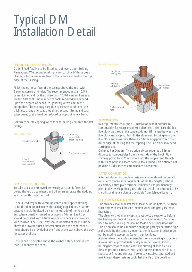
Typical DM Installation Detail
RENDERED STACK OPTIONCode 4 lead flashing to be fitted at roof level as per Building Regulations. We recommend that you scorch a 5-10mm deep channel into the outer surface of the casings and fold in the top edge of the flashing.
Finish the outer surface of the casings above the roof with 2 part waterproof render. The recommended mix is 1:2:5-6 cement:lime:sand for the undercoats. 1:2:8-9 cement:lime:sand for the final coat. The number of coats required will depend upon the degree of exposure, generally a two coat mix is acceptable. The mix may vary due to climate conditions, the thickness of any one coat should not exceed 15mm, and each subsequent coat should be reduced by approximately 3mm.
Isokern concrete capping for render to be lip glued onto the last casing.
TERMINATIONRaincap - Ventilated Option - (Installation with 0 distance to combustibles for straight rendered chimneys only). Take the last flue block up through the capping, do not fill the gap between the flue block and capping. Push fit the aluminium top ring onto the flue block and make sure there is a 10mm air gap between the outer edge of the ring and the capping. The flue block may need cutting to suit.Chimney Pot Option - This option always requires a 38mm distance to combustibles from the outside of the block. Fit a chimney pot at least 75mm down into the capping and flaunch with 1:3 cement and sharp sand to seal around. This option is not possible if 0 distance to combustibles is required.
AFTER COMPLETIONAfter installation is complete tests and checks should be carried out in accordance with document J of the Building Regulations. A chimney notice plate must be completed and permanently fixed in the dwelling, ideally near the electrical consumer unit. The checklist and notice plate are available from Schiedel Isokern.
USE AND MAINTENANCEThe chimney should be left for at least 72 hours before use, then start only with small fires for the first week and gently increase thereafter.The chimney should be swept at least twice a year, once before the heating season and once after the heating season. You may need to sweep during the heating season depending upon use. The brush should be a medium density polypropylene bristle type and should be the same diameter as the flue. Steel brushes must not be used to sweep the Isokern pumice flues.Always follow the appliance manufacturer’s operating instructions. Always burn approved fuels or dry seasoned wood. Avoid burning unseasoned wood and slow burning of solid fuels as this can produce excessive soot and condensation which in turn cause soot fires and damage. If correctly installed, operated and maintained these systems could last the life of the dwelling.
BRICK STACK OPTIONTo take brick or stonework externally a corbel is fitted just below the roof. Use trusses and trimmers to brace the cladding as it passes through the roof.
Code 4 lead tray with 50mm upstands and stepped flashing to be fitted in accordance with Building Regulations. A 50mm upstand should be fitted tight to the outside of the flue block and where possible turned in by approx 10mm. Lead trays should be coated with bituminous paint where it is in contact with mortar. The D.P.C. tray should be fitted at least 150mm above the lowest point of intersection with the roof. Weep holes should be provided at the front of the stack above the tray for water drainage.
Casings can be deleted above the corbel if stack height is less than 1.4m above the roof.
Code 4 lead flashing(not supplied)
Capping for render
Waterproof render
RENDERED STACK 10mm gap for ventilationunder Top Ring
BRICKWORK STACK
Corbel for brick stack
Lead tray and flashing Weep holes
above tray
Flue block or chimney pot
15
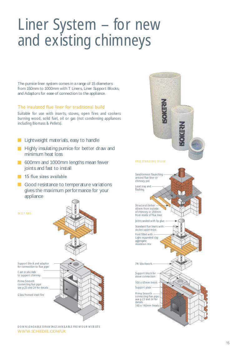
Liner System – for new and existing chimneys
The pumice liner system comes in a range of 15 diameters from 150mm to 1000mm with T Liners, Liner Support Blocks, and Adaptors for ease of connection to the appliance.
Suitable for use with inserts, stoves, open fires and cookers burning wood, solid fuel, oil or gas (not condensing appliances including Biomass & Pellets).
INSET FIRE
Support block and adaptor for connection to flue pipe
Cast in situ slabto support chimney
Glass fronted inset f ire
Prima Smoothconnecting flue pipe see p.23 and 24 for details
FREE STANDING STOVE
Sand/cement flaunching around flue liner or chimney pot
Lead tray and flashing
Structural timber40mm from outsideof chimney or 200mmfrom inside of f lue liner
Support block for stove connection
Support plate
7N blockwork
Joints sealed with lip glue
Standard flue liners with socket uppermost
Void filled with Light expanded clay aggregate insulation mix
140 x 140mm lintels
100 x 65mm lintels
Prima Smoothconnecting flue pipe see p.23 and 24 for details
Lightweight materials, easy to handle
Highly insulating pumice for better draw and minimum heat loss
600mm and 1000mm lengths mean fewer joints and fast to install
Good resistance to temperature variations gives the maximum performance for your appliance
DOWNLOADABLE DRAWINGS AVAILABLE FROM OUR WEB SITE
WWW.SCHIEDEL.COM/UK
16
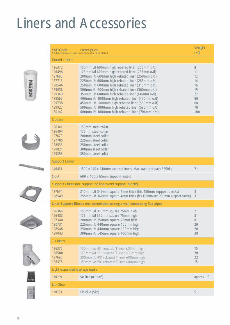
Liners and Accessories
SAP Code DescriptionWeight (kg)
Round Liners
126372126498127685127715128546129036129360129567129738129927130142
150mm i/d 600mm high rebated liner (200mm o/d)175mm i/d 600mm high rebated liner (235mm o/d)200mm i/d 600mm high rebated liner (250mm o/d)225mm i/d 600mm high rebated liner (285mm o/d)250mm i/d 600mm high rebated liner (310mm o/d)300mm i/d 600mm high rebated liner (360mm o/d)350mm i/d 600mm high rebated liner (416mm o/d) 400mm i/d 1000mm high rebated liner (470mm o/d) 450mm i/d 1000mm high rebated liner (530mm o/d)500mm i/d 1000mm high rebated liner (590mm o/d)600mm i/d 1000mm high rebated liner (706mm o/d)
8111214161927506070100
Collars
126361126494127673127705128533129021129356
150mm steel collar 175mm steel collar200mm steel collar225mm steel collar250mm steel collar300mm steel collar350mm steel collar
Support Lintel
146431 1500 x 140 x 140mm support lintels Max load (per pair) 3250kg 71
COA 600 x 100 x 65mm support lintels
Support Plates (for supporting liners and support blocks)
127694128549
210mm i/d 340mm square 4mm thick (fits 150mm support blocks)255mm i/d 360mm square 4mm thick (fits 175mm and 200mm support blocks)
33
126366126483127340130731128548129043
150mm i/d 310mm square 75mm high175mm i/d 350mm square 75mm high200mm i/d 350mm square 75mm high225mm i/d 440mm square 100mm high250mm i/d 440mm square 100mm high300mm i/d 545mm square 100mm high
788202030
T Liners
126376126500127695126375
15202215
Light expanded clay aggregate
130769 50 litre (0.05m3) approx. 19
Lip Glue
130771 Lip glue (5kg) 5
All dimensions are external unless otherwise stated

17
Liners and Accessories
SAP Code DescriptionWeight (kg)
Liner Bends
126364126365126367
456
126364126365126367
45
127679127680127681
568
127706127707127708
789
128542128531128532
8910
129015129016131819
101112
129354129355131820
131416
Stainless Steel Adaptors with Sealing Rope (for connection to support block)
126373126499127691127719128547129039
150mm i/d (205mm o/d)175mm i/d (235mm o/d)200mm i/d (255mm o/d)225mm i/d (290mm o/d)250mm i/d (315mm o/d)300mm i/d (365mm o/d)
Stainless Steel Increaser Adaptors with Sealing Rope (for connection to support block)
126357126493127671127672127704
125-150mm i/d (205mm o/d)150-175mm i/d (235mm o/d)150-200mm i/d (255mm o/d)175-200mm i/d (255mm o/d)200-225mm i/d (290mm o/d)
Stainless Steel Adaptors with Sealing Rope (for connection to T liners)
125453 126358146412 146413
125-150mm i/d (210mm o/d)150mm i/d (210mm o/d)150-175mm i/d (240mm o/d)175mm i/d (240mm o/d)
All dimensions are external unless otherwise stated
Larger diameter bends available on request.
18
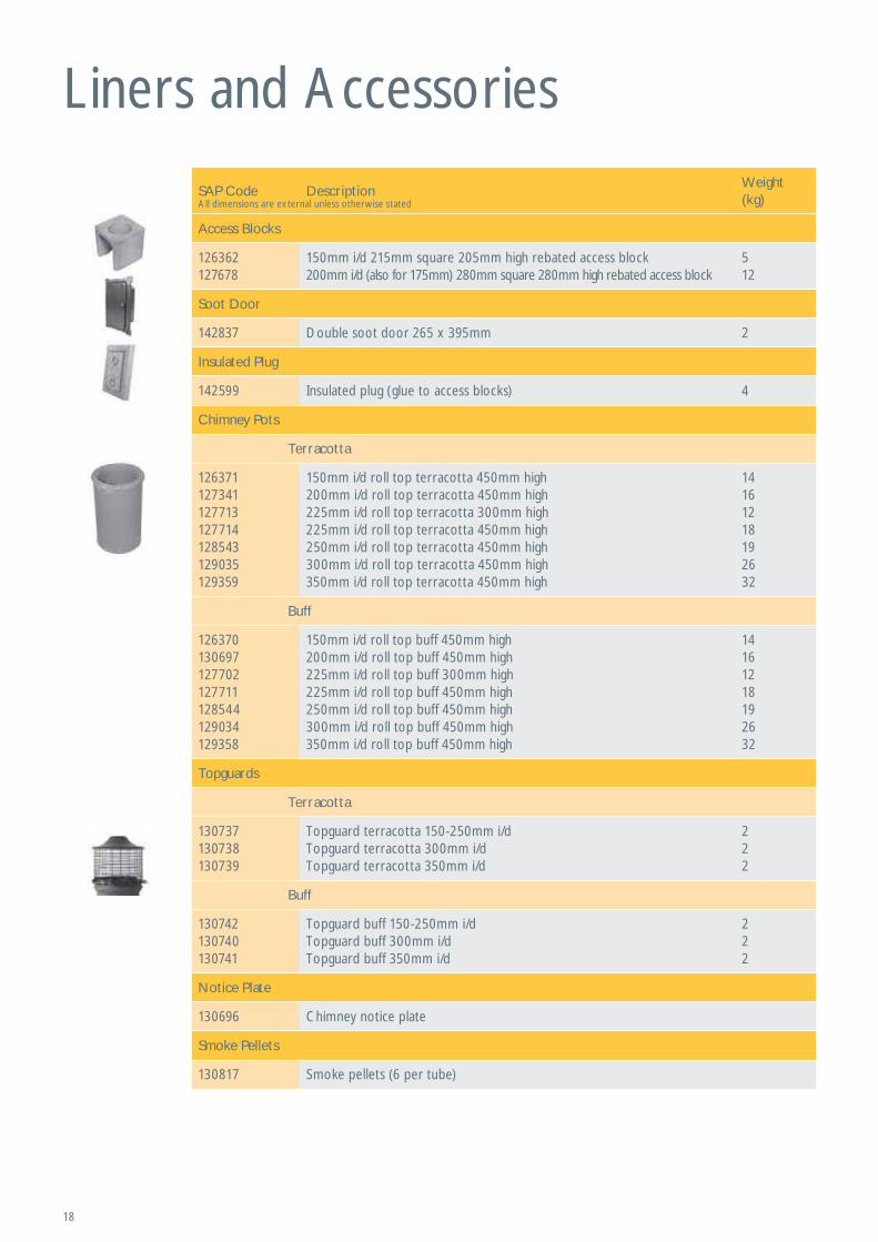
Liners and Accessories
SAP Code DescriptionWeight (kg)
Access Blocks
126362127678
150mm i/d 215mm square 205mm high rebated access block200mm i/d (also for 175mm) 280mm square 280mm high rebated access block
512
Soot Door
142837 Double soot door 265 x 395mm 2
Insulated Plug
142599 Insulated plug (glue to access blocks) 4
Chimney Pots
Terracotta
126371127341127713127714128543129035129359
150mm i/d roll top terracotta 450mm high200mm i/d roll top terracotta 450mm high225mm i/d roll top terracotta 300mm high225mm i/d roll top terracotta 450mm high250mm i/d roll top terracotta 450mm high300mm i/d roll top terracotta 450mm high350mm i/d roll top terracotta 450mm high
14161218192632
Buff
126370130697127702127711128544129034129358
150mm i/d roll top buff 450mm high200mm i/d roll top buff 450mm high225mm i/d roll top buff 300mm high225mm i/d roll top buff 450mm high250mm i/d roll top buff 450mm high300mm i/d roll top buff 450mm high350mm i/d roll top buff 450mm high
14161218192632
Topguards
Terracotta
130737130738130739
Topguard terracotta 150-250mm i/dTopguard terracotta 300mm i/dTopguard terracotta 350mm i/d
222
Buff
130742130740130741
Topguard buff 150-250mm i/dTopguard buff 300mm i/dTopguard buff 350mm i/d
222
Notice Plate
130696 Chimney notice plate
Smoke Pellets
130817 Smoke pellets (6 per tube)
All dimensions are external unless otherwise stated
19
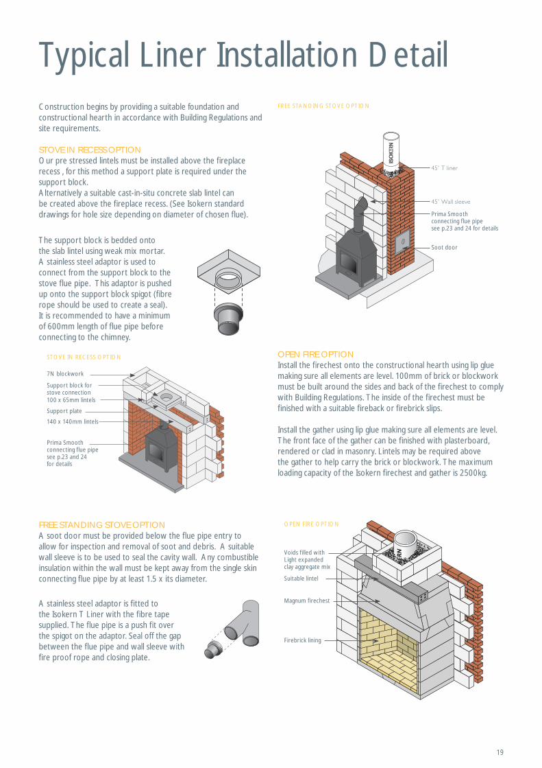
Typical Liner Installation DetailConstruction begins by providing a suitable foundation and constructional hearth in accordance with Building Regulations and site requirements.
STOVE IN RECESS OPTIONOur pre stressed lintels must be installed above the fireplace recess , for this method a support plate is required under the support block.Alternatively a suitable cast-in-situ concrete slab lintel can be created above the fireplace recess. (See Isokern standard drawings for hole size depending on diameter of chosen flue).
The support block is bedded onto the slab lintel using weak mix mortar. A stainless steel adaptor is used to connect from the support block to the stove flue pipe. This adaptor is pushed up onto the support block spigot (fibre rope should be used to create a seal). It is recommended to have a minimum of 600mm length of flue pipe before connecting to the chimney.
A stainless steel adaptor is fitted to the Isokern T Liner with the fibre tape supplied. The flue pipe is a push fit over the spigot on the adaptor. Seal off the gap between the flue pipe and wall sleeve with fire proof rope and closing plate.
FREE STANDING STOVE OPTIONA soot door must be provided below the flue pipe entry to allow for inspection and removal of soot and debris. A suitable wall sleeve is to be used to seal the cavity wall. Any combustible insulation within the wall must be kept away from the single skin connecting flue pipe by at least 1.5 x its diameter.
OPEN FIRE OPTIONInstall the firechest onto the constructional hearth using lip glue making sure all elements are level. 100mm of brick or blockwork must be built around the sides and back of the firechest to comply with Building Regulations. The inside of the firechest must be finished with a suitable fireback or firebrick slips.
Install the gather using lip glue making sure all elements are level. The front face of the gather can be finished with plasterboard, rendered or clad in masonry. Lintels may be required above the gather to help carry the brick or blockwork. The maximum loading capacity of the Isokern firechest and gather is 2500kg.
FREE STANDING STOVE OPTION
OPEN FIRE OPTION
Firebrick lining
Suitable lintel
Magnum firechest
Voids filled withLight expanded clay aggregate mix
STOVE IN RECESS OPTION
Soot door
Prima Smoothconnecting flue pipe see p.23 and 24 for details
Support block for stove connection
Support plate
7N blockwork
140 x 140mm lintels
100 x 65mm lintels
Prima Smoothconnecting flue pipe see p.23 and 24for details
20
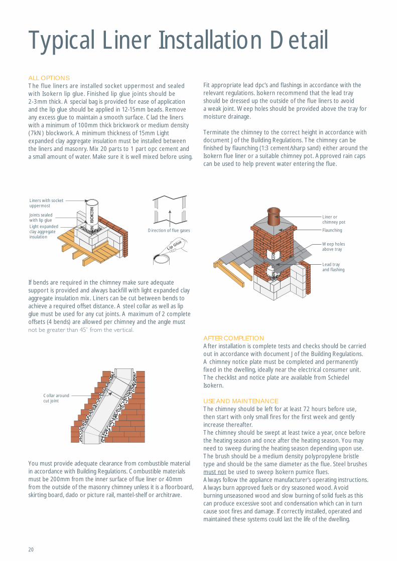
Typical Liner Installation DetailALL OPTIONSThe f lue liners are installed socket uppermost and sealed with Isokern lip glue. Finished lip glue joints should be 2-3mm thick. A special bag is provided for ease of application and the lip glue should be applied in 12-15mm beads. Remove any excess glue to maintain a smooth surface. Clad the liners with a minimum of 100mm thick brickwork or medium density (7kN) blockwork. A minimum thickness of 15mm Light expanded clay aggregate insulation must be installed between the liners and masonry. Mix 20 parts to 1 part opc cement and a small amount of water. Make sure it is well mixed before using.
AFTER COMPLETIONAfter installation is complete tests and checks should be carried out in accordance with document J of the Building Regulations. A chimney notice plate must be completed and permanently fixed in the dwelling, ideally near the electrical consumer unit. The checklist and notice plate are available from Schiedel Isokern.
USE AND MAINTENANCEThe chimney should be left for at least 72 hours before use, then start with only small fires for the first week and gently increase thereafter.The chimney should be swept at least twice a year, once before the heating season and once after the heating season. You may need to sweep during the heating season depending upon use. The brush should be a medium density polypropylene bristle type and should be the same diameter as the flue. Steel brushes must not be used to sweep Isokern pumice flues.Always follow the appliance manufacturer’s operating instructions. Always burn approved fuels or dry seasoned wood. Avoid burning unseasoned wood and slow burning of solid fuels as this can produce excessive soot and condensation which can in turn cause soot fires and damage. If correctly installed, operated and maintained these systems could last the life of the dwelling.
Fit appropriate lead dpc’s and flashings in accordance with the relevant regulations. Isokern recommend that the lead tray should be dressed up the outside of the flue liners to avoid a weak joint. Weep holes should be provided above the tray for moisture drainage.
Terminate the chimney to the correct height in accordance with document J of the Building Regulations. The chimney can be finished by flaunching (1:3 cement/sharp sand) either around the Isokern flue liner or a suitable chimney pot. Approved rain caps can be used to help prevent water entering the flue.
You must provide adequate clearance from combustible material in accordance with Building Regulations. Combustible materials must be 200mm from the inner surface of flue liner or 40mm from the outside of the masonry chimney unless it is a floorboard, skirting board, dado or picture rail, mantel-shelf or architrave.
If bends are required in the chimney make sure adequate support is provided and always backfill with light expanded clay aggregate insulation mix. Liners can be cut between bends to achieve a required offset distance. A steel collar as well as lip glue must be used for any cut joints. A maximum of 2 complete offsets (4 bends) are allowed per chimney and the angle must
Direction of f lue gases
Liners with socket uppermost
Light expanded clay aggregate insulation
Joints sealedwith lip glue
Flaunching
Weep holes above tray
Lead tray and flashing
Liner or chimney pot
Lip Glue
Collar around cut joint
21
Firebrick lining
Suitable lintel
Magnum firechest
Voids filled withLight expanded clay aggregate mix
Firechests
market.
The Schiedel Isokern firechest complements the Isokern chimney systems which are designed to create a complete system, avoiding many of the variable factors that lead to draught problems and smoky fireplaces.
The Isokern firechest range is cast using lightweight, highly insulating pumice. The components interlock like pieces
THE MAGNUM FIRECHEST RANGE
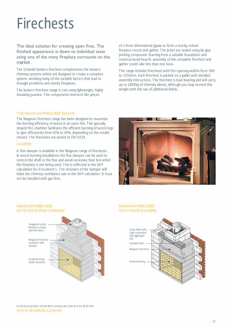
The Magnum Firechest range has been designed to maximise the burning efficiency of wood in an open fire. The specially shaped fire chamber facilitates the efficient burning of wood logs to give efficiencies from 41% to 45%, depending on the model chosen. The firechests are tested to EN13229.
DAMPER
A flue damper is available in the Magnum range of firechests. In wood burning installations the flue damper can be used to control the draft in the flue and avoid excessive heat loss when the fireplace is not being used. This is reflected in the SAP calculation for Document L. The inclusion of the damper will halve the chimney ventilation rate in the SAP calculation. It must not be installed with gas fires.
MAGNUM FIRECHEST WITH PUMICE LINERS
MAGNUM FIRECHEST WITH DM SYSTEM CHIMNEY
Staggered jointsbetween casingand flue block
Magnum firechestcomplete withdamper
Firebrick lining inside firechest
DOWNLOADABLE DRAWINGS AVAILABLE FROM OUR WEB SITE
WWW.SCHIEDEL.COM/UK
of a three dimensional jigsaw to form a sturdy, robust fireplace recess and gather. The joints are sealed using lip glue jointing compound. Starting from a suitable foundation and constructional hearth, assembly of the complete firechest and gather could take less than one hour.
The range includes firechests with fire opening widths from 500 to 1250mm. Each firechest is packed on a pallet with detailed assembly instructions. The firechest is load bearing and will carry up to 2600kg of chimney above, although you may exceed this weight with the use of additional lintels.
22
Firechests
SAP Code ModelOpening Width (mm)
Opening Height (mm)
Ext. Width (mm)
Ext Height (mm)
Ext. Depth (mm)
Weight (kg)
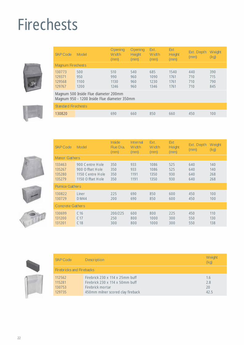
Magnum Firechests
130773129371129568129767
50095011001200
51099011301246
540960960960
685109012301346
1540176117611761
440710710710
390715790845
Magnum 500 Inside Flue diameter 200mmMagnum 950 - 1200 Inside Flue diameter 350mm
Standard Firechests
130820 690 660 850 660 450 100
SAP Code ModelInside Flue Dia. (mm)
Internal Width (mm)
Ext. Width (mm)
Ext Height (mm)
Ext. Depth (mm)
Weight (kg)
Manor Gathers
133463135267135280135279
900 Centre Hole900 Offset Hole1150 Centre Hole1150 Offset Hole
350350350350
93393311911191
1086108613501350
525525930930
640640640640
140140268268
Pumice Gathers
130822130729
LinerDM44
225200
690690
850850
600600
450450
100100
Concrete Gathers
130699131200131201
C16C17C18
200/225250300
600800800
80010001000
225300300
450550550
110130138
SAP Code DescriptionWeight (kg)
Firebricks and Firebacks
112562115281130753129735
Firebrick 230 x 114 x 25mm buffFirebrick 230 x 114 x 50mm buffFirebrick mortar450mm milner scored clay fireback
1.62.82042.5
23
225
1020
620 183
Min
600
150
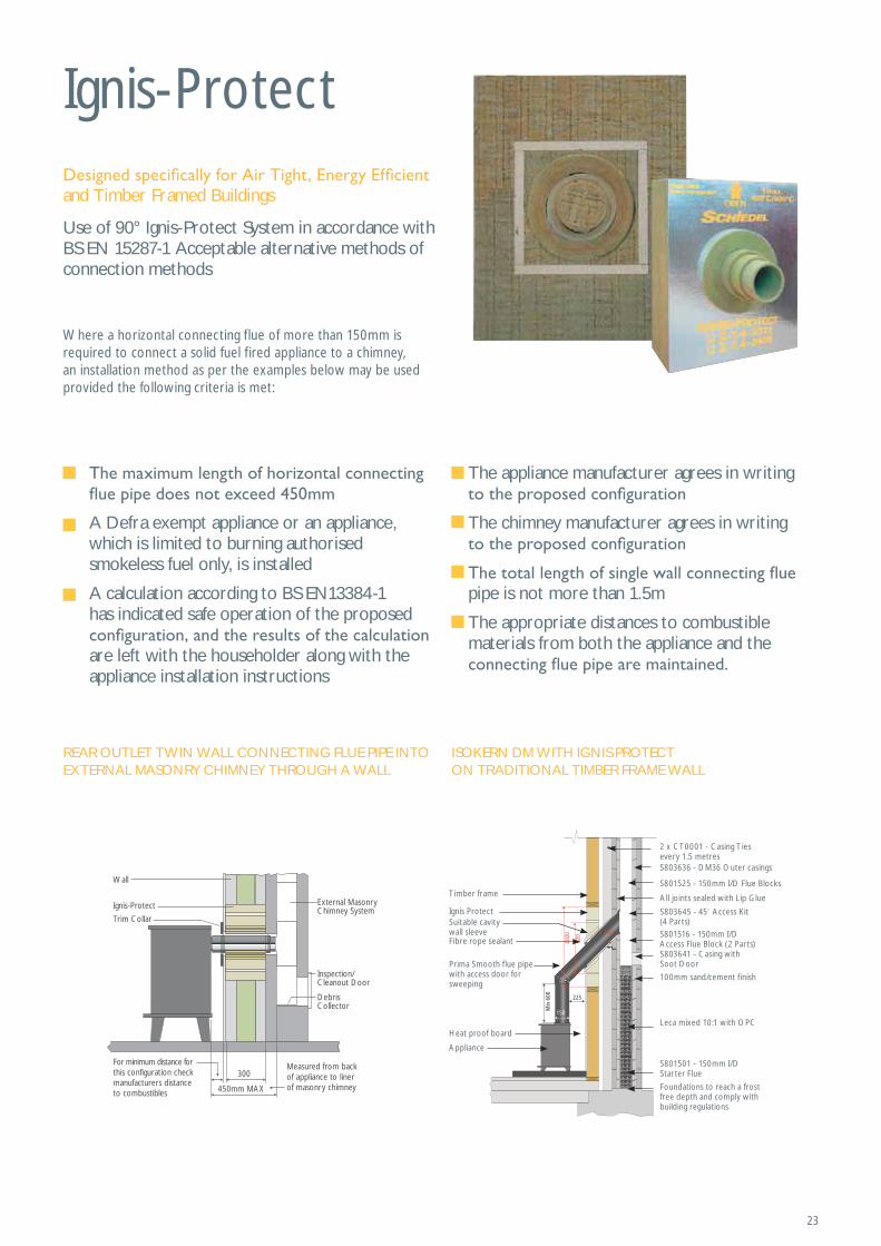
2 x CT0001 - Casing Ties every 1.5 metresS803636 - DM36 Outer casings
S801525 - 150mm I/D Flue Blocks
All joints sealed with Lip Glue
S803645 - 45 Access Kit(4 Parts)S801516 - 150mm I/D Access Flue Block (2 Parts)
Timber frame
Ignis ProtectSuitable cavity wall sleeveFibre rope sealant
Prima Smooth flue pipe with access door for sweeping
Heat proof board
Appliance
S803641 - Casing with Soot Door
100mm sand/cement finish
Leca mixed 10:1 with OPC
S801501 - 150mm I/D Starter Flue
Foundations to reach a frost free depth and comply with building regulations
Ignis-Protect
Use of 90° Ignis-Protect System in accordance with BS EN 15287-1 Acceptable alternative methods of connection methods
Where a horizontal connecting flue of more than 150mm is required to connect a solid fuel fired appliance to a chimney, an installation method as per the examples below may be used provided the following criteria is met:
A Defra exempt appliance or an appliance, which is limited to burning authorised smokeless fuel only, is installed
A calculation according to BS EN13384-1 has indicated safe operation of the proposed
are left with the householder along with the appliance installation instructions
REAR OUTLET TWIN WALL CONNECTING FLUE PIPE INTO EXTERNAL MASONRY CHIMNEY THROUGH A WALL
Measured from back of appliance to liner of masonry chimney
300
450mm MAX
External Masonry Chimney System
Inspection/Cleanout Door
Wall
Trim Collar
DebrisCollector
Ignis-Protect
For minimum distance for this configuration check manufacturers distanceto combustibles
and Timber Framed Buildings
ISOKERN DM WITH IGNIS PROTECT ON TRADITIONAL TIMBER FRAME WALL
The appliance manufacturer agrees in writing
The chimney manufacturer agrees in writing
pipe is not more than 1.5m
The appropriate distances to combustible materials from both the appliance and the
v
24
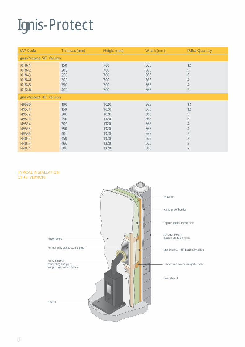
Ignis-Protect
TYPICAL INSTALLATION
Plasterboard
Plasterboard
Permanently elastic sealing strip
Timber framework for Ignis-Protect
Ignis-Protect - 45° External version
Vapour barrier membrane
Schiedel Isokern Double Module System
Insulation
Damp proof barrier
Hearth
Prima Smoothconnecting flue pipe see p.23 and 24 for details
SAP Code Thikness (mm) Height (mm) Width (mm) Pallet Quantity
101841101842101843101844101845101846
150200250300350400
700700700700700700
565565565565565565
1296442
149530 149531 149532 149533 149534 149535 149536144032144033144034
100150200250300350400450466500
1020102010201320132013201320132013201320
565565565565565565565565565565
181296442222
25
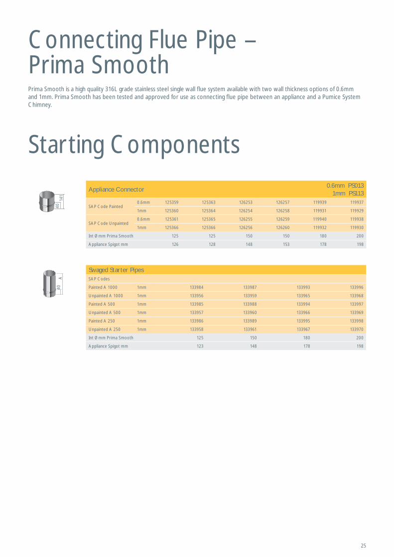
Connecting Flue Pipe – Prima Smooth
40A
4014
1
Starting Components
Prima Smooth is a high quality 316L grade stainless steel single wall flue system available with two wall thickness options of 0.6mm and 1mm. Prima Smooth has been tested and approved for use as connecting flue pipe between an appliance and a Pumice System Chimney.
Appliance Connector0.6mm PS013
1mm PS113
SAP Code Painted0.6mm 125359 125363 126253 126257 119939 119937
1mm 125360 125364 126254 126258 119931 119929
SAP Code Unpainted0.6mm 125361 125365 126255 126259 119940 119938
1mm 125366 125366 126256 126260 119932 119930
Int Ømm Prima Smooth 125 125 150 150 180 200
Appliance Spigot mm 126 128 148 153 178 198
Swaged Starter PipesSAP Codes
Painted A 1000 1mm 133984 133987 133993 133996
Unpainted A 1000 1mm 133956 133959 133965 133968
Painted A 500 1mm 133985 133988 133994 133997
Unpainted A 500 1mm 133957 133960 133966 133969
Painted A 250 1mm 133986 133989 133995 133998
Unpainted A 250 1mm 133958 133961 133967 133970
Int Ømm Prima Smooth 125 150 180 200
Appliance Spigot mm 123 148 178 198
26
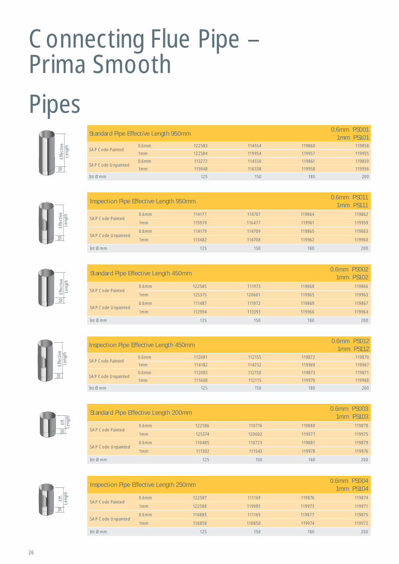
Pipes
50Ef
f.Le
ngth
50Ef
fect
ive
Leng
th50
Effe
ctiv
e Le
ngth
50Ef
fect
ive
Leng
th50
Eff.
Leng
th
Inspection Pipe Effective Length 950mm0.6mm PS011
1mm PS111
SAP Code Painted0.6mm 114177 114707 119864 119862
1mm 115979 116477 119961 119959
SAP Code Unpainted0.6mm 114179 114709 119865 119863
1mm 113482 114708 119962 119960
Int Ømm 125 150 180 200
Standard Pipe Effective Length 450mm0.6mm PS002
1mm PS102
SAP Code Painted0.6mm 122585 111973 119868 119866
1mm 125375 120601 119965 119963
SAP Code Unpainted0.6mm 111487 111972 119869 119867
1mm 112994 113393 119966 119964
Int Ømm 125 150 180 200
Inspection Pipe Effective Length 450mm0.6mm PS012
1mm PS112
SAP Code Painted0.6mm 112081 112155 119872 119870
1mm 114182 114252 119969 119967
SAP Code Unpainted0.6mm 112083 112150 119873 119871
1mm 111608 112115 119970 119968
Int Ømm 125 150 180 200
Standard Pipe Effective Length 200mm0.6mm PS003
1mm PS103
SAP Code Painted0.6mm 122586 110716 119880 119878
1mm 125374 120602 119977 119975
SAP Code Unpainted0.6mm 110485 110723 119881 119879
1mm 111302 111543 119978 119976
Int Ømm 125 150 180 200
Inspection Pipe Effective Length 250mm0.6mm PS004
1mm PS104
SAP Code Painted0.6mm 122587 111169 119876 119874
1mm 122588 119985 119973 119971
SAP Code Unpainted0.6mm 110885 111165 119877 119875
1mm 110850 110850 119974 119972
Int Ømm 125 150 180 200
50Ef
fect
ive
Leng
th
Standard Pipe Effective Length 950mm0.6mm PS001
1mm PS101
SAP Code Painted0.6mm 122583 114554 119860 119858
1mm 122584 119954 119957 119955
SAP Code Unpainted0.6mm 113272 114550 119861 119859
1mm 115948 116338 119958 119956
Int Ømm 125 150 180 200
Connecting Flue Pipe – Prima Smooth
27
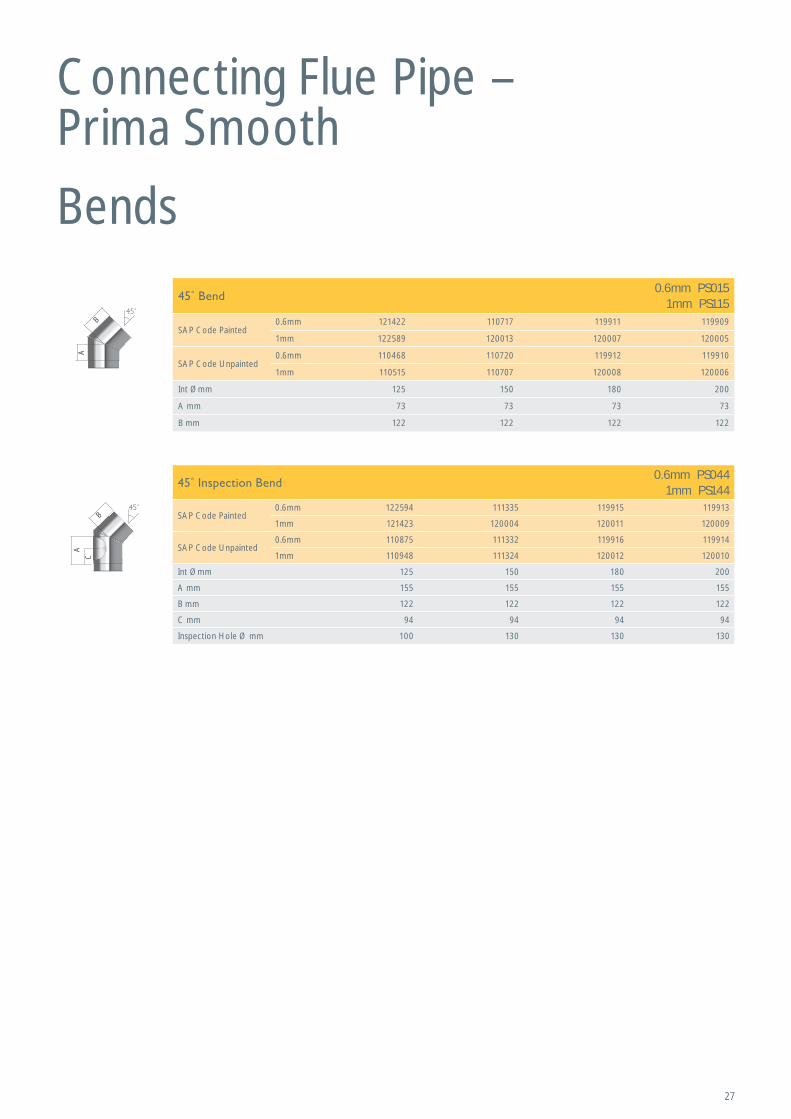
Bends
A
B
A
C
B
Connecting Flue Pipe – Prima Smooth
0.6mm PS0151mm PS115
SAP Code Painted0.6mm 121422 110717 119911 119909
1mm 122589 120013 120007 120005
SAP Code Unpainted0.6mm 110468 110720 119912 119910
1mm 110515 110707 120008 120006
Int Ømm 125 150 180 200
A mm 73 73 73 73
B mm 122 122 122 122
0.6mm PS0441mm PS144
SAP Code Painted0.6mm 122594 111335 119915 119913
1mm 121423 120004 120011 120009
SAP Code Unpainted0.6mm 110875 111332 119916 119914
1mm 110948 111324 120012 120010
Int Ømm 125 150 180 200
A mm 155 155 155 155
B mm 122 122 122 122
C mm 94 94 94 94
Inspection Hole Ø mm 100 130 130 130
28
450
260
A
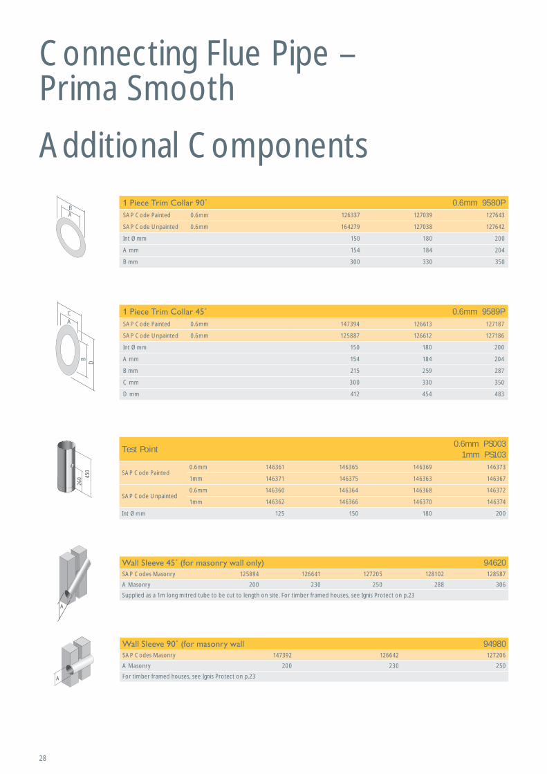
Additional Components
A
Test Point0.6mm PS003
1mm PS103
SAP Code Painted0.6mm 146361 146365 146369 146373
1mm 146371 146375 146363 146367
SAP Code Unpainted0.6mm 146360 146364 146368 146372
1mm 146362 146366 146370 146374
Int Ømm 125 150 180 200
94620SAP Codes Masonry 125894 126641 127205 128102 128587
A Masonry 200 230 250 288 306
Supplied as a 1m long mitred tube to be cut to length on site. For timber framed houses, see Ignis Protect on p.23
94980SAP Codes Masonry 147392 126642 127206
A Masonry 200 230 250
For timber framed houses, see Ignis Protect on p.23
Connecting Flue Pipe – Prima Smooth
AB
C
DB
A
0.6mm 9580PSAP Code Painted 0.6mm 126337 127039 127643
SAP Code Unpainted 0.6mm 164279 127038 127642
Int Ømm 150 180 200
A mm 154 184 204
B mm 300 330 350
0.6mm 9589PSAP Code Painted 0.6mm 147394 126613 127187
SAP Code Unpainted 0.6mm 125887 126612 127186
Int Ømm 150 180 200
A mm 154 184 204
B mm 215 259 287
C mm 300 330 350
D mm 412 454 483
29
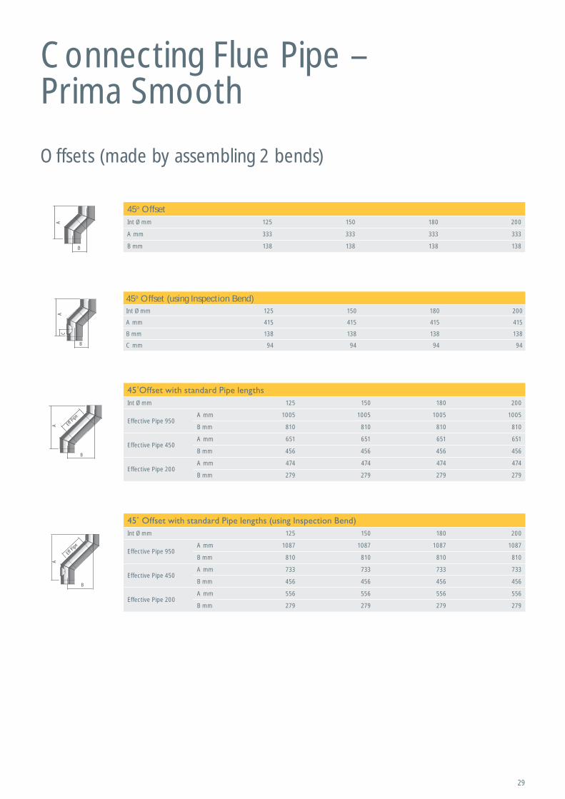
Connecting Flue Pipe – Prima Smooth
Offsets (made by assembling 2 bends)
A
B
A
B
Eff Pi
pe
A
B
Eff Pi
pe
AC
B
45o OffsetInt Ømm 125 150 180 200
A mm 333 333 333 333
B mm 138 138 138 138
45o Offset (using Inspection Bend)Int Ømm 125 150 180 200
A mm 415 415 415 415
B mm 138 138 138 138
C mm 94 94 94 94
Int Ømm 125 150 180 200
Effective Pipe 950A mm 1005 1005 1005 1005
B mm 810 810 810 810
Effective Pipe 450A mm 651 651 651 651
B mm 456 456 456 456
Effective Pipe 200A mm 474 474 474 474
B mm 279 279 279 279
Int Ømm 125 150 180 200
Effective Pipe 950A mm 1087 1087 1087 1087
B mm 810 810 810 810
Effective Pipe 450A mm 733 733 733 733
B mm 456 456 456 456
Effective Pipe 200A mm 556 556 556 556
B mm 279 279 279 279
30
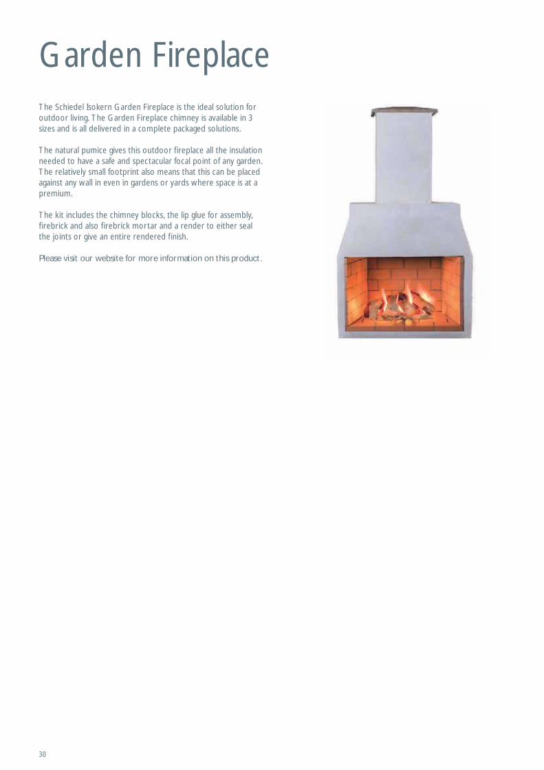
Garden FireplaceThe Schiedel Isokern Garden Fireplace is the ideal solution for outdoor living. The Garden Fireplace chimney is available in 3 sizes and is all delivered in a complete packaged solutions.
The natural pumice gives this outdoor fireplace all the insulation needed to have a safe and spectacular focal point of any garden. The relatively small footprint also means that this can be placed against any wall in even in gardens or yards where space is at a premium.
The kit includes the chimney blocks, the lip glue for assembly, firebrick and also firebrick mortar and a render to either seal the joints or give an entire rendered finish.
Please visit our website for more information on this product.
31
Useful Charts and Information
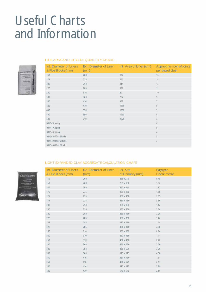
FLUE AREA AND LIP GLUE QUANTITY CHART
LIGHT EXPANDED CLAY AGGREGATE CALCULATION CHART
Int. Diameter of Liners & Flue Blocks (mm)
Ext. Diameter of Liner (mm)
Int. Area of Liner (cm2) Approx number of joints per bag of glue
150 200 177 16
175 235 240 14
200 250 314 12
225 285 397 11
250 310 491 10
300 360 707 9
350 416 962 7
400 470 1256 6
450 530 1590 5
500 590 1963 5
600 710 2826 4
DM36 Casing 6
DM44 Casing 5
DM54 Casing 4
DM36 Offset Blocks 5
DM44 Offset Blocks 3
DM54 Offset Blocks
Int. Diameter of Liners & Flue Blocks (mm)
Ext. Diameter of Liner (mm) of Chimney (mm)
Bags perLinear metre
150 200 235 x235 0.48
150 200 235 x 350 1.02
150 200 350 x 350 1.82
175 235 350 x 350 1.58
175 235 350 x 460 2.35
175 235 460 x 460 3.36
200 250 350 x 350 1.47
200 250 350 x 460 2.24
200 250 460 x 460 3.25
225 285 350 x 350 1.17
225 285 350 x 460 1.94
225 285 460 x 460 2.96
250 310 350 x 350 0.94
250 310 350 x 460 1.71
250 310 460 x 460 2.72
300 360 460 x 460 2.20
300 360 460 x 575 3.25
300 360 575 x 575 4.58
350 416 460 x 460 1.51
350 416 460 x 575 2.57
350 416 575 x 575 3.89
400 470 575 x 575 3.14
32
Useful Charts and Information
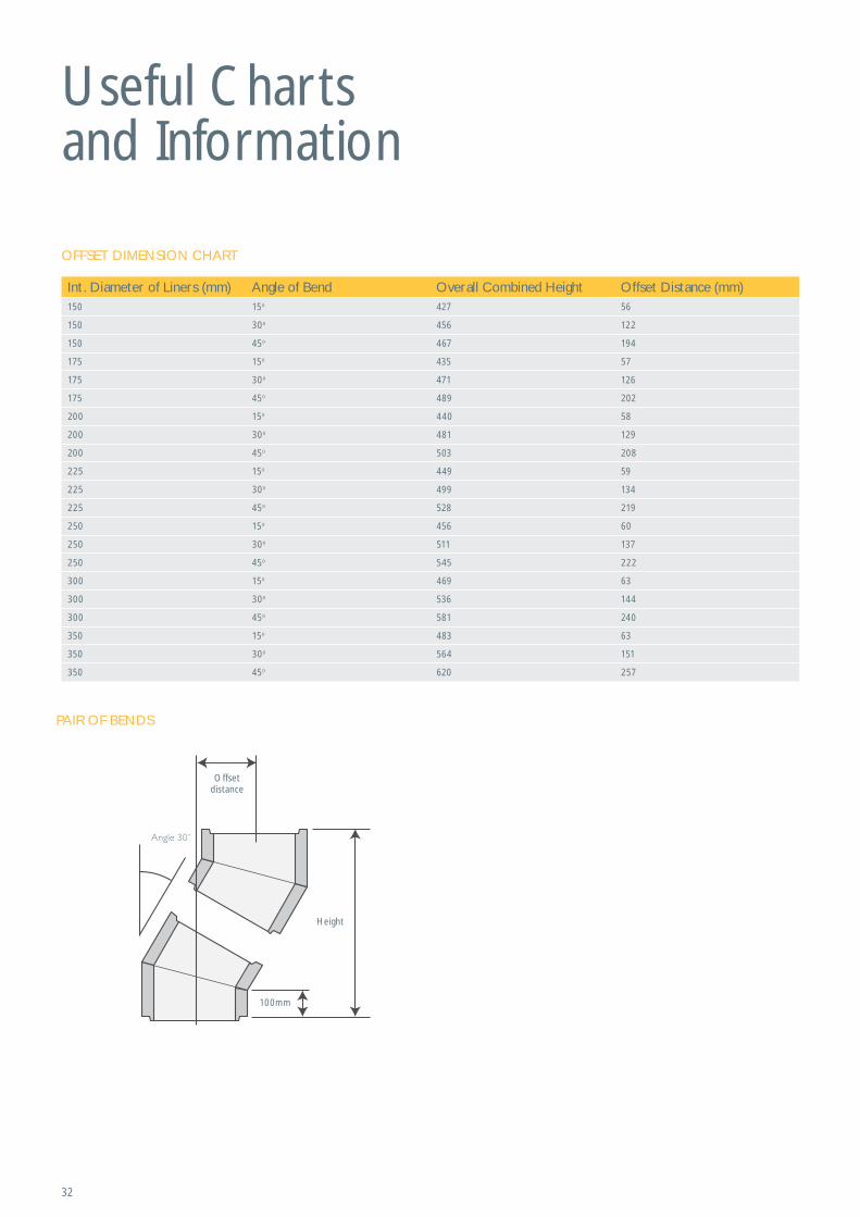
Offsetdistance
Height
100mm
PAIR OF BENDS
OFFSET DIMENSION CHART
Int. Diameter of Liners (mm) Angle of Bend Overall Combined Height Offset Distance (mm)150 15o 427 56
150 30o 456 122
150 45o 467 194
175 15o 435 57
175 30o 471 126
175 45o 489 202
200 15o 440 58
200 30o 481 129
200 45o 503 208
225 15o 449 59
225 30o 499 134
225 45o 528 219
250 15o 456 60
250 30o 511 137
250 45o 545 222
300 15o 469 63
300 30o 536 144
300 45o 581 240
350 15o 483 63
350 30o 564 151
350 45o 620 257
33
Useful Charts and Information
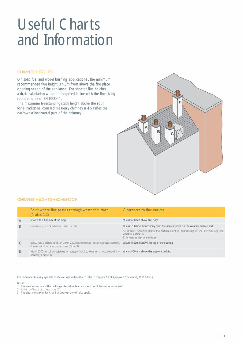
A
D
B C
For clearances to easily ignitable roof coverings such as thatch refer to diagram 2.2 of Approved Document J 2010 Edition
CHIMNEY HEIGHTS ABOVE ROOF
NOTES1. The weather surface is the building external surface, such as its roof, tiles or external walls.2. 3. The clearances given for A or B as appropriate will also apply.
CHIMNEY HEIGHTS
On solid fuel and wood burning applications , the minimum recommended flue height is 4.5m from above the fire place opening or top of the appliance . For shorter flue heights a draft calculation would be required in line with the flue sizing requirements of EN13384-1.The maximum freestanding stack height above the roof for a traditional coursed masonry chimney is 4.5 times the narrowest horizontal part of the chimney.
(Notes 1,2)
A at or within 600mm of the ridge at least 600mm above the ridge
B at least 2300mm horizontally from the nearest point on the weather surface and:
weather surface: or
C at least 1000mm above the top of the opening
D at least 600mm above the adjacent building

34
Useful Charts and InformationVENTILATION REQUIREMENTSIt is very important that sufficient air for combustion and ventilation is provided to the room containing the appliance, to enable correct and efficient working of the appliance and chimney system. Reference should be made to the appliance manufacturer’s instructions and recommendations are also given in the Building Regulations Document J, see below:
The carbon monoxide alarms should comply with BS EN 50291:2001.
The carbon monoxide alarm must be located in the same room as the appliance:a) On the ceiling at least 300mm from any wall or if it is located on a wall, as high up as possible (above any doors and windows), but not within 150mm of the ceiling and
b) between 1m and 3m horizontally from the appliance.
N.B Provision of a carbon monoxide alarm should not be regarded as a substitute for correct installation and regular servicing.
CARBON MONOXIDE ALARMSWhere a new or replacement fixed solid fuel appliance is installed in a dwelling, a carbon monoxide alarm shouldbe provided in the room where the appliance is located.
VENTILATION REQUIREMENTS FOR SOLID FUEL
Notes: 1. Equivalent area is as measured according to the method in BS EN 13141-1:2004 or estimated according to paragraph 1.14. Divide the area given in mm2 by 100 to find the
corresponding area in cm2.2. For simple open fires as depicted in Diagram 29, the requirement can be met with room ventilation areas as follows:
3. Example: an appliance with a f lue draught stabiliser and a rated output of 7kW would require an equivalent area of (5 x 300) + (2 x 850) = 3200mm2 4. It is unlikely that a dwelling constructed prior to 2008 will have an air permeability of less than 5.0m3/h.m2) at 50Pa unlessextensive measures have been taken to improve air-
tightness. See Appendix F.
MAGNUM COMBUSTION AIR REQUIREMENT MAGNUM FIREBRICK, LIP GLUE & MORTAR QUANTITY
Size of Magnum Firechest Free Air in cm2 Free Air in mm2
500 200 20.000
950 248 24.800
1100 338 33.800
1200 385 38.500
Size of Magnum Firechest
25mm thick Bricks
50mm thick Bricks
Lip Glue
Firebrick Mortar
500 Included Included 2 Included
950 40 34 5 2
1100 40 44 6 2
1200 40 48 6 2
Type of Appliance Type and amount of Ventilation (1)
Permanently open air vents as below:3 2
300mm2
850mm2
If design air permeability 3 2
850mm2
Permanently open vents as below:3 2
550mm2
If design air permeability 3 2
550mm2
Nominal f ire size (fireplace opening size) 500mm 450mm 400mm 350mm
Total equivalent area of permanently open air vents 20,500mm2 18,500mm2 16,500mm2 14,500mm2
35
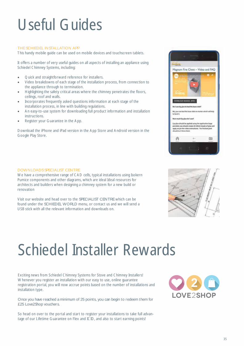
Useful GuidesTHE SCHIEDEL INSTALLATION APPThis handy mobile guide can be used on mobile devices and touchscreen tablets.
It offers a number of very useful guides on all aspects of installing an appliance using Schiedel Chimney Systems, including:
• Quick and straightforward reference for installers.• Video breakdowns of each stage of the installation process, from connection to
the appliance through to termination.• Highlighting the safety critical areas where the chimney penetrates the floors,
ceilings, roof and walls.• Incorporates frequently asked questions information at each stage of the
installation process, in line with building regulations.• An easy-to-use system for downloading full product information and installation
instructions.• Register your Guarantee in the App.
Download the iPhone and iPad version in the App Store and Android version in the Google Play Store.
DOWNLOADS SPECIALIST CENTREWe have a comprehensive range of CAD cells, typical installations using Isokern Pumice components and other diagrams, which are ideal Ideal resources for architects and builders when designing a chimney system for a new build or renovation
Visit our website and head over to the SPECIALIST CENTRE which can be found under the SCHIEDEL WORLD menu, or contact us and we will send a USB stick with all the relevant information and downloads on.
Schiedel Installer RewardsExciting news from Schiedel Chimney Systems for Stove and Chimney Installers! Whenever you register an installation with our easy to use, online guarantee registration portal, you will now accrue points based on the number of installations and installation type.
Once you have reached a minimum of 25 points, you can begin to redeem them for £25 Love2Shop vouchers.
So head on over to the portal and start to register your installations to take full advan-tage of our Lifetime Guarantee on Flex and ICID, and also to start earning points!
Schiedel Chimney Systems Ltd.Unit 8 & 9, Block A, Holton RoadHolton Heath Industrial EstatePoole, Dorset BH16 6LGTel. +44 (0)1202 861650 [email protected]/uk
Follow us on Social Media @SchiedelUK
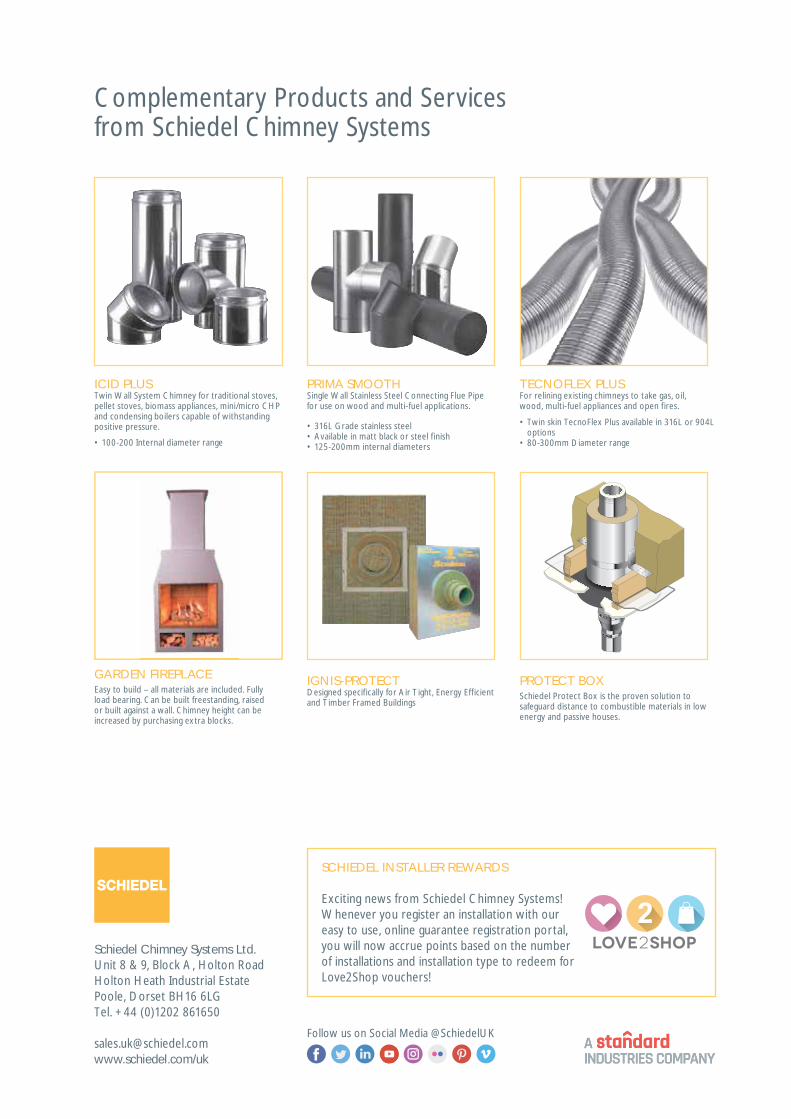
Complementary Products and Services from Schiedel Chimney Systems
TECNOFLEX PLUSFor relining existing chimneys to take gas, oil,wood, multi-fuel appliances and open fires.
ICID PLUSTwin Wall System Chimney for traditional stoves, pellet stoves, biomass appliances, mini/micro CHP and condensing boilers capable of withstanding positive pressure.
PRIMA SMOOTHSingle Wall Stainless Steel Connecting Flue Pipe for use on wood and multi-fuel applications.
IGNIS-PROTECTDesigned specif ically for Air Tight, Energy Eff icient and Timber Framed Buildings
PROTECT BOXSchiedel Protect Box is the proven solution to safeguard distance to combustible materials in low energy and passive houses.
GARDEN FIREPLACEEasy to build – all materials are included. Fully load bearing. Can be built freestanding, raised or built against a wall. Chimney height can be increased by purchasing extra blocks.
• 100-200 Internal diameter range
• 316L Grade stainless steel• Available in matt black or steel f inish• 125-200mm internal diameters
• Twin skin TecnoFlex Plus available in 316L or 904L options
• 80-300mm Diameter range
SCHIEDEL INSTALLER REWARDS
Exciting news from Schiedel Chimney Systems! Whenever you register an installation with our easy to use, online guarantee registration portal, you will now accrue points based on the number of installations and installation type to redeem for Love2Shop vouchers!