Embed Size (px)
Citation preview
International Refereed Journal of Engineering and Science (IRJES)
ISSN (Online) 2319-183X, (Print) 2319-1821
Volume 5, Issue 12 (December 2016), PP.55-69
www.irjes.com 55 | Page
Isolation Performance of Optimized Triple Friction Pendulum
Felix Weber1, Hans Distl
2, Christian Braun
3
1(Maurer Switzerland GmbH, Zurich, Switzerland)
2(Maurer Engineering GmbH & Co. KG, Munich, Germany)
3(MAURER SE, 80807 Munich, Germany)
Abstract: This paper compares the isolation performance of the triple friction pendulum (FP) with that of the
double FP as benchmark. First, both FPs are optimized for minimum absolute structural acceleration. In order to
break down the hardly tractable optimization problem of the triple FP with 12 parameters to a manageable
optimization task it is assumed that the effective radii 1 and 4 are given by the targeted isolation time period and
the parameters of the articulated slider are selected according to the design philosophy of the triple FP. As a
result, the triple FP can be optimized by variation of its friction coefficients 1 and 4 only; the double FP with
same isolation time period is optimized by variation of its friction coefficients 1 and 2. Due to the nonlinearity
of FPs the optimizations are performed for four accelerograms of real earthquakes in order to take into account
the different frequency content of different earthquakes and for three selected PGAs representing smaller,
medium and larger DBEs. Subsequent to the optimizations, the optimized FPs are assessed in terms of absolute
structural acceleration and total bearing motion for the same earthquakes but scaled to a wide range of PGAs up
to the value corresponding to the MCE in order to perform the assessment for all possibly occurring
earthquakes. The results reveal that the absolute structural accelerations and total bearing displacements due to
the optimized triple and double FPs are very similar within the entire PGA range.
Keywords: Earthquake, isolation, seismic; triple friction pendulum, optimization
I. INTRODUCTION
The base isolation of civil engineering structures is the common countermeasure against hazardous
structural vibrations due to earthquake excitation [1-4]. Various types of elastomeric bearings and spherical
friction pendulums (FP) belong to the class of passive isolators that exert the superposition of a stiffness force
and damping force [5-11]. For minimum structural response the stiffness is designed to significantly increase the
fundamental period of the isolated structure with the constraint of the re-centring condition and the friction is
tuned to add damping to the structure at isolation frequency [12-15]. Due to the nonlinearity of the friction force
the effective damping ratio of the isolator depends on the bearing displacement amplitude [16]. Therefore, the
friction coefficient can only be optimized for one selected peak ground acceleration (PGA) value of the
earthquake which commonly corresponds to the design basis earthquake (DBE). Consequently, the added
damping and the isolation of the structure, respectively, are suboptimal for earthquakes with smaller and larger
PGAs. This drawback of conventional FPs may be solved by active, semi-active and hybrid isolation systems
based on controlled hydraulic actuators [17], variable orifice dampers [18], variable stiffness devices [19, 20],
shape memory alloys [21], electrorheological dampers [22] and magnetorheological dampers [23-25] due to
their ability to emulate controllable stiffness and damping forces [26, 27].
The economic disadvantages of these control-based solutions triggered the development of adaptive
FPs whose stiffness and friction properties depend on the displacement amplitude at which the FP is operated.
Besides double FPs with articulated slider in order to design the double FP with different radii and friction
coefficients [28] the triple FP represents a promising solution as these devices exhibit significant adaptability. A
detailed description of the working principle, the modelling and testing of triple FPs can be found in, e.g., [29-
34]. According to [29] the triple FP is conceptualized to produce low friction combined with high stiffness at
small bearing displacements and PGAs, respectively, generate increasing friction combined with softening
behaviour at medium to large PGAs due to the DBE and the maximum credible earthquake (MCE), and exhibit
stiffening behaviour at bearing displacement amplitudes and PGAs, respectively, resulting from earthquakes
beyond the MCE. As a result, the isolation performance of the triple FP has to be assessed for various PGA
values in order to ensure that the triple FP is operated within all its sliding regimes with associated equivalent
stiffness and damping parameters [35, 36]. These investigations are based on the triple FP as designed in [29]
which represents a mock-up FP for laboratory scale experiments which explains the fairly low isolation time
period of 1.87 s. In contrast to these investigations the aim of the present paper is:
a) first, to optimize the triple FP for a selected earthquake scaled to three different PGA values representing a
rather small, a medium and a rather large DBE, and
Isolation Performance Of Optimized Triple Friction Pendulum
www.irjes.com 56 | Page
b) second, to assess the optimized triple FP in terms of absolute structural acceleration (and drift) and total
bearing displacement (costs of bearing) within the entire PGA range up to the MCE.
As the structure is simplified by a 1-degree-of-dreedom system the drifts are in proportion to the
absolute structural accelerations whereby the assessment results of the drifts are omitted. Both the absolute
structural accelerations and the total bearing displacements are compared with those obtained from the
optimized double FP as benchmark.
The layout of the paper is as follows. First, the optimization procedures of the triple and double FPs
based on the targeted isolation time period are described in section 2. The modelling of the structure and the FPs
is given in section 3. The optimization results of the triple and double FPs for several ground acceleration time
histories that are scaled to three PGA values representing three different DBEs are given in section 4. Section 5
shows and discusses the isolation performance results due to the optimized triple and double FPs for various
PGA values ranging from 0.25 m/s2 up to 150% of the PGA used for optimization in order to assess the FPs also
at smaller and larger PGAs than used for optimization. The paper is closed by a summary and conclusions given
in section 6.
II. OPTIMIZATION OF TRIPLE FRICTION PENDULUM The dynamic behaviour of the triple FP is determined by 12 parameters, i.e. four friction coefficients,
four effective radii and four displacement capacities of the four sliding surfaces (Fig. 1(a)). Hence, the
optimization of the triple FP in general is a hardly tractable optimization problem. In the following it is
explained how this complex optimization task can be broken down to a simplified optimization procedure
without losing the main features of the triple FP. In the subsequent section it will be shown that the simplified
optimization procedure leads to verifiable optimization results as the optimization functions can displayed by
three-dimensional graphs which proof that the global extremum is found by the optimization routine.
2.1 Optimization Criterion
The optimal triple and double FPs are those which minimize the absolute maximum of the absolute
acceleration of the structure due to earthquake ground excitation [23]
gs uumaxmin (1)
where su denotes the acceleration of the structure relative to the ground and gu is the ground
acceleration. The structural drift is not considered as additional optimization criterion because absolute
structural accelerations are in in proportion to structural drifts if the structure is modelled by a single degree-of-
freedom system as it is commonly done when the optimization of the isolator is of concern, see e.g. [36].
2.2 Optimization For 12 Different DBEs
The friction and stiffness parameters of the triple FP vary as function of the total bearing displacement
due to the different sliding regimes of the triple FP [29, 30, 36]. Hence, both the friction and the stiffness
parameters of the triple FP are nonlinear functions of the total bearing motion amplitude whereby also the
optimization of the triple FP depends on the bearing displacement amplitude. In order to take into account the
displacement dependency of these parameters the triple FP is optimized for minimum absolute acceleration of
the building (1) using four different accelerograms that are scaled to three selected PGAs representing three
different design basis earthquakes:
optPGA =2.5 m/s2 representing a rather small DBE,
optPGA =5.0 m/s2 representing a medium DBE, and
optPGA =7.5 m/s2 representing a rather large DBE.
Since four earthquakes are considered, i.e. the accelerograms of the measured El Centro North-South
(NS), Kobe, Loma Prieta and Northridge earthquakes, that are scaled to three different PGAs, in fact, the
optimizations are performed four 12 different DBEs. Hence, the triple FP is not only optimized for different
PGAs but also different frequency contents of earthquakes. To ensure comparability, the double FP that also
exhibits nonlinear behaviour due to its friction force is optimized for the same four accelerograms that are scaled
to the same three values of optPGA .
2.3 Assessment For All Possible PGAs Of Earthquakes
Once the triple FPs (and double FP as benchmark) are optimized for the selected 12 DBEs the
optimized triple FPs are assessed in terms absolute structural acceleration extreme for the same four earthquakes
representing different frequency contents but scaled to various PGAs in order to assess the isolation

Isolation Performance Of Optimized Triple Friction Pendulum
www.irjes.com 57 | Page
performance of the triple FPs that are optimized at one specific PGA ( optPGA ) also for the cases that
earthquakes with smaller and larger PGAs occur. This is done by scaling the accelerograms of the four selected
earthquakes to the PGA values ranging from 0.25 m/s2 up to 150% of optPGA (2). This wide range ensures that
the isolation performance (1) is computed for very small but frequently occurring earthquakes far below the
DBE, for small to medium earthquakes below and in the vicinity of the DBE and for earthquakes stronger than
the DBE. The maximum PGA value considered in this study is selected as 150% of optPGA which may
represent the PGA of the MCE.
opt22 PGA5.1,...,s/m50.0,s/m25.0:)PGA(rangeassessment (2)
2.4 Isolation Time Period
The isolation time period isolationT is a design parameter of the isolation system. Common practice is to
select isolationT between 3 s to 4 s whereby the response of the structure becomes smaller than gu even without
damping in the isolator [16]. In this study isolationT =3.5 s is selected which yields the effective radius effR of the
spherical isolator as follows
m044.32
TgR
2
isolationeff
(3)
where g denotes the acceleration of gravity. The lower isolation time period of the triple FP is given
by the sum of the effective radii 1effR and 4effR of sliding surfaces 1 and 4 (Fig. 1(a)). The literature survey
on triple FPs shows that 4eff1eff RR is adopted which leads to the effective radii 1 and 4 as follows
(Table 1)
m522.12
Tg
2
1RR
2
isolation4eff1eff
(4)
Figure 1. Sketches of triple (a) and double (b) FPs with articulated sliders.
In case of non-adaptive double FPs it is common practice to design both spherical surfaces with the
same effective radii, that is (Fig. 1(b))
m522.12
Tg
2
1RR
2
isolation2eff1eff
(5)
The geometrical radii follow from the effective radii (4, 5) and the heights ih according to iieffi hRR
(Fig. 1, Table 1).
2.5 Sliding Regime V
The sliding regime V is activated when the restrainers (end stoppers) of sliding surfaces 1 and 4 are
triggered whereby sliding only occurs at surfaces 2 and 3 and consequently friction and stiffness of sliding
regime V are determined by the low friction and high stiffness properties of surfaces 2 and 3 of the articulated
slider assembly of the triple FP [29, 30, 36]. According to the design philosophy of the triple FP given in [29]
the aim of sliding regime V is not to generate good isolation of the structure but to limit the required
displacement capacity of the triple FP by its stiffening behaviour. As the goal of the optimization procedure here
is to minimize the acceleration response of the structure, the sliding regime V is not relevant. Therefore, the
triple FP is computed without restrainers 1 and 4 whereby sliding regime V is not triggered at any level of PGA.
Isolation Performance Of Optimized Triple Friction Pendulum
www.irjes.com 58 | Page
As a result, the displacement capacities 1d and 4d , respectively, do not require to be specified for the
optimization of the triple FP. It should be added that neglecting the end stoppers 1 and 4 will result in slightly
better isolation results, i.e. slightly lower structural accelerations, as the stiffening behaviour of sliding regime V
is not triggered during the optimization runs. To ensure comparability, the optimization of the double FP is also
performed without end stoppers.
2.6 Parameters Of Articulated Slider Assembly Of Triple FP
The intension of the articulated slider assembly is to initiate relative motion between slider and sliding
surfaces 2 and 3 at very small PGAs and also if the friction coefficient might be higher during the first couple of
cycles due to dry friction effects. The design philosophy is therefore to select small values for the friction
coefficients of sliding surfaces 2 and 3. According to the theoretical and experimental results described in [29,
30] the low friction coefficients of sliding surfaces 2 and 3 are selected as follows
%75.132 (6)
Analogically to the common design approach 4eff1eff RR the effective radii 2effR and 3effR of
the articulated slider assembly are also chosen to be equal, i.e. 3eff2eff RR , which is in agreement with the
design methodology given in the literature. As the aim of the slider assembly is to combine low friction with
high stiffness, see [29], the effective radii 2 and 3 are designed far smaller than those of sliding surfaces 1 and 4;
in case of the triple FP described in [29] 3eff2eff RR are designed to be 8.21 times smaller than
4eff1eff RR . This design rule is also adopted here which leads to
m190.08
RRR
1eff3eff2eff
(7)
The displacement capacities 2d and 3d of the articulated slider assembly are up-scaled in the same
way as the effective radii of sliding surfaces 2 and 3 are greater than those presented in [29]. This proportional
up-scaling design yields
m07.0dd 32 (8)
Notice that 2d and 3d hardly influence the optimization results since the restrainers on surfaces 2 and
3 are triggered when the triple FP is operated in sliding regime V and the total displacement capacity is used.
However, as restrainers 1 and 4 are omitted for the optimization for the reasons described in section 2.5, also the
end stoppers on surfaces 2 and 3 are not activated. Only in case of very high friction coefficients of 15% and
higher on surfaces 1 and 4 restrainers 2 and 3 might be triggered. As such high friction coefficients far from
being optimal, m07.0dd 32 does not influence the optimal solution.
2.7 Optimization Parameters
The selection of the isolation time period and adopting the common design philosophy for the friction
coefficients, effective radii and displacement capacities of the articulated slider assemble of the triple FP, the
hardly tractable optimization problem of the triple FP with 12 parameters is broken down a simpler optimization
problem with two parameters, i.e. 1 and 4 . Due to the reduced complexity of the optimization problem it is
guaranteed that the globally optimal parameters 1 and 4 are identified. In addition, the resulting three-
dimensional optimization function allows plotting it as a three-dimensional surface showing the sensitivity of
1 and 4 on the resulting absolute structural acceleration. For the less complex double FP the selection of the
isolation time period, which is the same as for the triple FP to ensure fair comparison, yields 2eff1eff RR
according to (5). As the double FP does not include restrainers, the double FP can optimized by variation of its
friction coefficients 1 and 2 . In the optimization process 1 and 2 can take different (and equal) values.
Different friction coefficients result in different relative motions on surfaces 1 and 2. Therefore, an articulated
slider for the double FP is considered (Fig.1(b)).
2.8 Optimization Procedure
The triple and double FPs are optimized in the following way (Table 1):
a) The coupled nonlinear equations of motion of the structure with FP (described in section 3) are solved in
the time domain.
b) The El Centro NS, the Kobe, the Loma Prieta and the Northridge accelerograms are adopted for the ground
excitation of the isolated structure.

Isolation Performance Of Optimized Triple Friction Pendulum
www.irjes.com 59 | Page
c) The accelerograms are scaled to the three design values optPGA at which the FPs are optimized (section
2.2).
d) The friction coefficients 1 and 4 of the triple FP and 1 and 2 of the double FP, respectively, are
varied within 0.5% to 25% with increment of 0.5%.
e) For each optPGA -scaled earthquake and for each combination of the friction coefficients 1 and 4 of the
triple FP and 1 and 2 of the double FP, respectively, one full time history analysis of the isolated
structure is computed which gives approx. 10800 optimization runs for the triple FP and the same amount
for the double FP.
f) Each run is evaluated in terms of absolute structural acceleration )uumax( gs .
Figure 2. Example of one optimization run for El Centro NS accelerogram scaled to optPGA =7.5 m/s2 and triple
FP with 1 =3% and 4 =11% triggering sliding regimes I, II and III.
Table 1. Parameters of realistic triple and double FPs for isolationT =3.5 s.
triple FP double FP
parameters
determined by
isolationT and
common design
approach
4eff1eff RR 1.522 m
3eff2eff RR 0.190 m
32 1.75%
32 dd 0.07 m
2eff1eff RR 1.522 m
optimization parameters 1 and 4 1 and 2
variation range 0.5% to 25%
with increment of 0.5%
0.5% to 25%
with increment of 0.5%
geometrical parameters of realistic
FP
41 RR 1.722 m
32 RR 0.310 m
41 hh 0.20 m
32 hh 0.12 m
41 dd 0.23 m
totd 0.60 m
4m 853 kg
3m 258 kg
2m 465 kg (slider)
21 RR 1.722 m
21 hh 0.20 m
41 dd 0.30 m
totd 0.60 m
2m 853 kg
1m 465 kg (slider)
Isolation Performance Of Optimized Triple Friction Pendulum
www.irjes.com 60 | Page
An example of one optimization run is depicted in Fig. 2. The selected ground acceleration is the
accelerogram of the El Centro North-South earthquake that is scaled to optPGA =7.5 m/s2 (Fig. 2(a)). The triple
FP is computed for the selected friction coefficients 1 =3% and 4 =11% whereby sliding regimes I
(articulated slider assembly), II and III are activated (Fig. 2(b)). The absolute acceleration )t(u)t(u gs of the
structure is computed as function of time by solving the coupled nonlinear equations of motion of the structure
with triple FP (section 3) in the time domain for the selected ground excitation. Subsequent to each run of one
full time history, the absolute maximum )uumax( gs of the absolute structural acceleration is determined by
post-processing.
III. MODELLING 3.1 Structure With Triple FP
The structural properties are selected so that the building with base isolation represents a very typical
case. The natural frequency sfr of the structure without base isolation is assumed to be 1.2 Hz whereby its
natural period of 0.833 s is close to or even within the plateau of the response spectrum. Such a building
therefore requires being base isolated. In view of the isolation time period of 3.5 s, which is more than three
times longer than the time period of the non-isolated structure, it is common practice to model the isolated
building as a single degree-of-freedom system [37]. The according equation of motion of the structure coupled
to the bearing plate 4 of the triple FP becomes
gs4ss4ssss umuukuucum (9)
where sm (=1223.2 metric tonnes), sc and sk are the modal mass, the viscous damping coefficient
(corresponding to the modal damping ratio )mk2/(c ssss =1%) and the stiffness coefficient of the
structure; su , su and su are the relative displacement, velocity and acceleration of the structure while 4u and
4u denote the displacement and velocity of bearing plate 4 of the triple FP relative to the ground. The equation
of motion of bearing plate 4 with mass 4m is
g44ss4ss344eff
4h44 umuuk)uu(cuuR
Wfum
(10)
where 4hf describes the friction force of sliding surface 4 by the hysteretic friction force model [38]
sliding:uusgnW
slidingpre:uukf
344
34h4h
(11)
where the pre-sliding stiffness coefficient hk is considered to be two orders of magnitude greater than
the stiffness due to the effective radius 4effR and W =12000 kN denotes the vertical load on the triple FP. iu ,
iu and iu are the relative displacement, velocity and acceleration of plate i (Fig. 1(a)). Since the simulations
are made without the consideration of sliding regime V as explained in section 2.5, equation (10) does not
include any restrainer force. The equation of motion of sliding plate 3 with mass 3m becomes
g3344eff
4h3r233eff
3h33 umuuR
Wffuu
R
Wfum
(12)
where 3hf is the friction force of sliding surface 3 that is modelled similarly to (11). 3rf describes
the force of the restrainer of concave plate 3 that is assumed to be a linear stiffness force if the restrainer is
triggered [29]
323
32323323r3r
duu:0
duu:uusgnduukf (13)
where rk denotes the restrainer stiffness coefficient that is also assumed to be two orders of magnitude
greater than 4effR/W . The equation of motion of the slider with mass 2m is
g23r233eff
3h2r122eff
2h22 umfuuR
Wffuu
R
Wfum
(14)
where 2hf is the friction force and 2rf the restrainer force of sliding surface 2; both forces are
modelled analogically to (11) and (13), respectively. The equation of motion of concave plate 1 with mass 1m
Isolation Performance Of Optimized Triple Friction Pendulum
www.irjes.com 61 | Page
becomes
g12r122eff
2h11eff
1h11 umfuuR
Wfu
R
Wfum
(15)
where the friction force 1hf is a function of 1u only
sliding:usgnW
slidingpre:ukf
11
1h1h
(16)
As for concave plate 4 also concave plate 1 does not include a restrainer. Hence, there is no restrainer
force on the left side of equation (15).
3.2 Structure With Double FP
The modelling of the structure with double friction pendulum is analogue that of the building with
triple friction pendulum with the basic difference that only three coupled nonlinear differential equations must
be solved due to the mass of the building, the mass of plate 2 of the double FP and the mass of the slider of the
double FP.
3.3 Simulation Tool
The coupled nonlinear differential equations of the structure with triple FP and double FP, respectively,
are programmed in Matlab/Simulink® environment and solved in the time domain using the solver
ode15s(stiff/NDF) with variable step size with upper bound of 0.1 ms and relative tolerance of 1e-3.
IV. OPTIMIZATION RESULTS
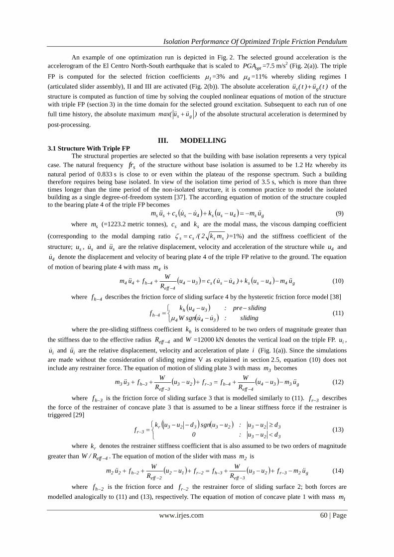
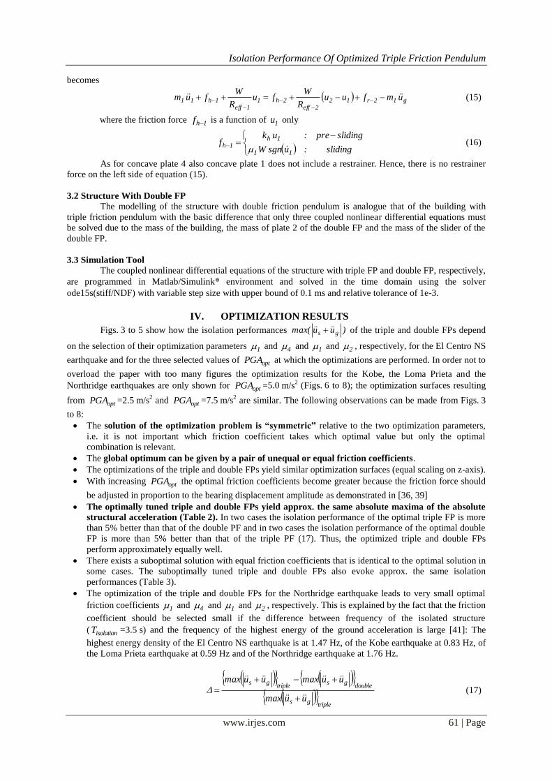
Figs. 3 to 5 show how the isolation performances )uumax( gs of the triple and double FPs depend
on the selection of their optimization parameters 1 and 4 and 1 and 2 , respectively, for the El Centro NS
earthquake and for the three selected values of optPGA at which the optimizations are performed. In order not to
overload the paper with too many figures the optimization results for the Kobe, the Loma Prieta and the
Northridge earthquakes are only shown for optPGA =5.0 m/s2 (Figs. 6 to 8); the optimization surfaces resulting
from optPGA =2.5 m/s2 and optPGA =7.5 m/s
2 are similar. The following observations can be made from Figs. 3
to 8:
The solution of the optimization problem is “symmetric” relative to the two optimization parameters,
i.e. it is not important which friction coefficient takes which optimal value but only the optimal
combination is relevant.
The global optimum can be given by a pair of unequal or equal friction coefficients.
The optimizations of the triple and double FPs yield similar optimization surfaces (equal scaling on z-axis).
With increasing optPGA the optimal friction coefficients become greater because the friction force should
be adjusted in proportion to the bearing displacement amplitude as demonstrated in [36, 39]
The optimally tuned triple and double FPs yield approx. the same absolute maxima of the absolute
structural acceleration (Table 2). In two cases the isolation performance of the optimal triple FP is more
than 5% better than that of the double PF and in two cases the isolation performance of the optimal double
FP is more than 5% better than that of the triple PF (17). Thus, the optimized triple and double FPs
perform approximately equally well.
There exists a suboptimal solution with equal friction coefficients that is identical to the optimal solution in
some cases. The suboptimally tuned triple and double FPs also evoke approx. the same isolation
performances (Table 3).
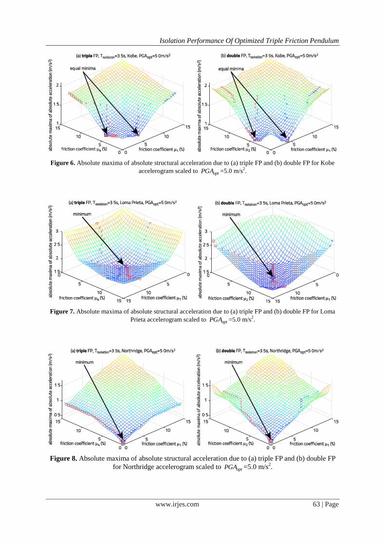
The optimization of the triple and double FPs for the Northridge earthquake leads to very small optimal
friction coefficients 1 and 4 and 1 and 2 , respectively. This is explained by the fact that the friction
coefficient should be selected small if the difference between frequency of the isolated structure
( isolationT =3.5 s) and the frequency of the highest energy of the ground acceleration is large [41]: The
highest energy density of the El Centro NS earthquake is at 1.47 Hz, of the Kobe earthquake at 0.83 Hz, of
the Loma Prieta earthquake at 0.59 Hz and of the Northridge earthquake at 1.76 Hz.
triplegs
doublegs
triplegs
uumax
uumaxuumax
(17)
Isolation Performance Of Optimized Triple Friction Pendulum
www.irjes.com 62 | Page
Figure 3. Absolute maxima of absolute structural acceleration due to (a) triple FP and (b) double FP for El
Centro NS accelerogram scaled to optPGA =2.5 m/s2.
Figure 4. Absolute maxima of absolute structural acceleration due to (a) triple FP and (b) double FP for El
Centro NS accelerogram scaled to optPGA =5.0 m/s2.
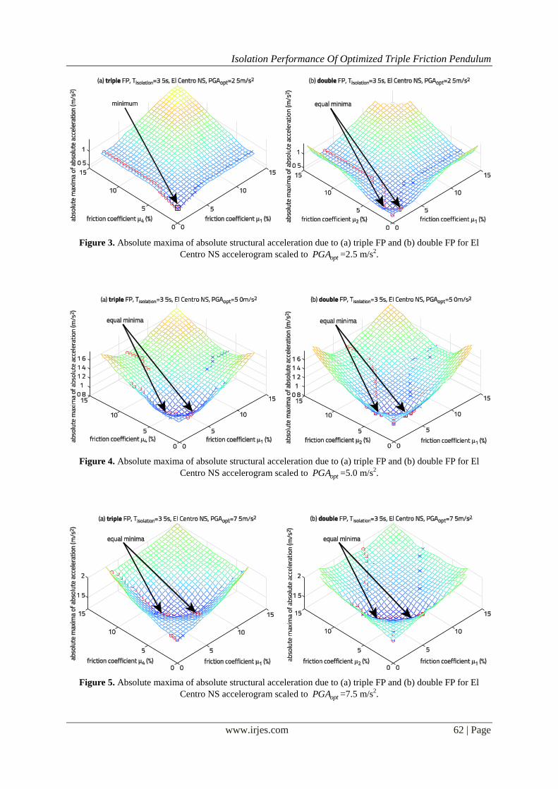
Figure 5. Absolute maxima of absolute structural acceleration due to (a) triple FP and (b) double FP for El
Centro NS accelerogram scaled to optPGA =7.5 m/s2.
Isolation Performance Of Optimized Triple Friction Pendulum
www.irjes.com 63 | Page
Figure 6. Absolute maxima of absolute structural acceleration due to (a) triple FP and (b) double FP for Kobe
accelerogram scaled to optPGA =5.0 m/s2.
Figure 7. Absolute maxima of absolute structural acceleration due to (a) triple FP and (b) double FP for Loma
Prieta accelerogram scaled to optPGA =5.0 m/s2.
Figure 8. Absolute maxima of absolute structural acceleration due to (a) triple FP and (b) double FP
for Northridge accelerogram scaled to optPGA =5.0 m/s2.
Isolation Performance Of Optimized Triple Friction Pendulum
www.irjes.com 64 | Page
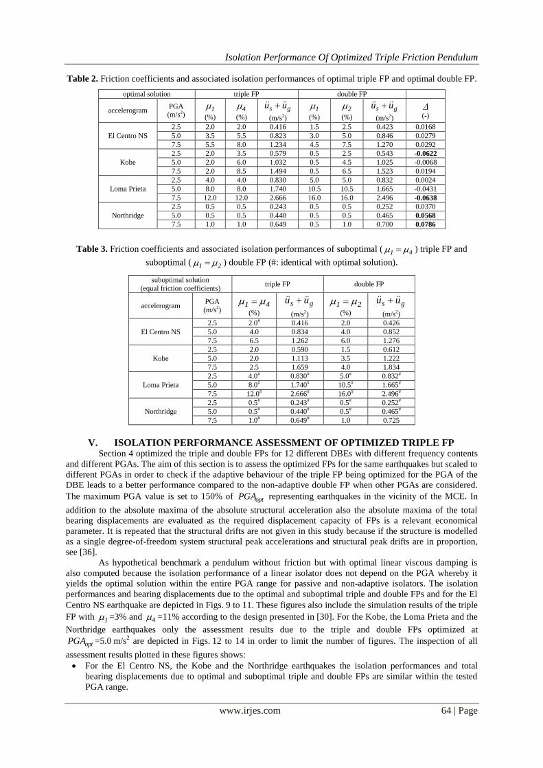
Table 2. Friction coefficients and associated isolation performances of optimal triple FP and optimal double FP.
optimal solution triple FP double FP
accelerogram PGA (m/s2)
1
(%)
4
(%)
gs uu
(m/s2)
1
(%)
2
(%)
gs uu
(m/s2)
(-)
El Centro NS
2.5 2.0 2.0 0.416 1.5 2.5 0.423 0.0168
5.0 3.5 5.5 0.823 3.0 5.0 0.846 0.0279
7.5 5.5 8.0 1.234 4.5 7.5 1.270 0.0292
Kobe
2.5 2.0 3.5 0.579 0.5 2.5 0.543 -0.0622
5.0 2.0 6.0 1.032 0.5 4.5 1.025 -0.0068
7.5 2.0 8.5 1.494 0.5 6.5 1.523 0.0194
Loma Prieta
2.5 4.0 4.0 0.830 5.0 5.0 0.832 0.0024
5.0 8.0 8.0 1.740 10.5 10.5 1.665 -0.0431
7.5 12.0 12.0 2.666 16.0 16.0 2.496 -0.0638
Northridge
2.5 0.5 0.5 0.243 0.5 0.5 0.252 0.0370
5.0 0.5 0.5 0.440 0.5 0.5 0.465 0.0568
7.5 1.0 1.0 0.649 0.5 1.0 0.700 0.0786
Table 3. Friction coefficients and associated isolation performances of suboptimal ( 41 ) triple FP and
suboptimal ( 21 ) double FP (#: identical with optimal solution).
suboptimal solution
(equal friction coefficients) triple FP double FP
accelerogram PGA (m/s2)
41
(%)
gs uu
(m/s2)
21
(%)
gs uu
(m/s2)
El Centro NS
2.5 2.0# 0.416 2.0 0.426
5.0 4.0 0.834 4.0 0.852
7.5 6.5 1.262 6.0 1.276
Kobe
2.5 2.0 0.590 1.5 0.612
5.0 2.0 1.113 3.5 1.222
7.5 2.5 1.659 4.0 1.834
Loma Prieta
2.5 4.0# 0.830# 5.0# 0.832#
5.0 8.0# 1.740# 10.5# 1.665#
7.5 12.0# 2.666# 16.0# 2.496#
Northridge
2.5 0.5# 0.243# 0.5# 0.252#
5.0 0.5# 0.440# 0.5# 0.465#
7.5 1.0# 0.649# 1.0 0.725
V. ISOLATION PERFORMANCE ASSESSMENT OF OPTIMIZED TRIPLE FP Section 4 optimized the triple and double FPs for 12 different DBEs with different frequency contents
and different PGAs. The aim of this section is to assess the optimized FPs for the same earthquakes but scaled to
different PGAs in order to check if the adaptive behaviour of the triple FP being optimized for the PGA of the
DBE leads to a better performance compared to the non-adaptive double FP when other PGAs are considered.
The maximum PGA value is set to 150% of optPGA representing earthquakes in the vicinity of the MCE. In
addition to the absolute maxima of the absolute structural acceleration also the absolute maxima of the total
bearing displacements are evaluated as the required displacement capacity of FPs is a relevant economical
parameter. It is repeated that the structural drifts are not given in this study because if the structure is modelled
as a single degree-of-freedom system structural peak accelerations and structural peak drifts are in proportion,
see [36].
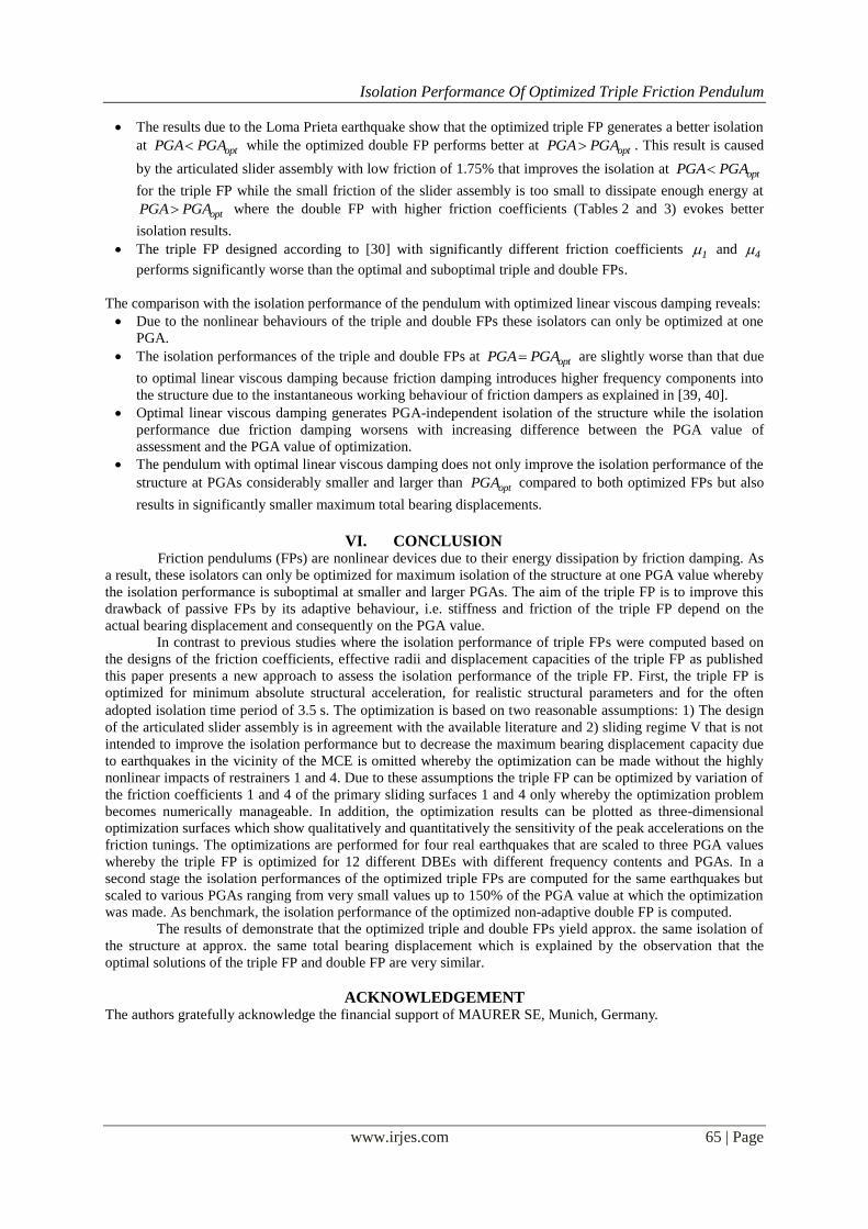
As hypothetical benchmark a pendulum without friction but with optimal linear viscous damping is
also computed because the isolation performance of a linear isolator does not depend on the PGA whereby it
yields the optimal solution within the entire PGA range for passive and non-adaptive isolators. The isolation
performances and bearing displacements due to the optimal and suboptimal triple and double FPs and for the El
Centro NS earthquake are depicted in Figs. 9 to 11. These figures also include the simulation results of the triple
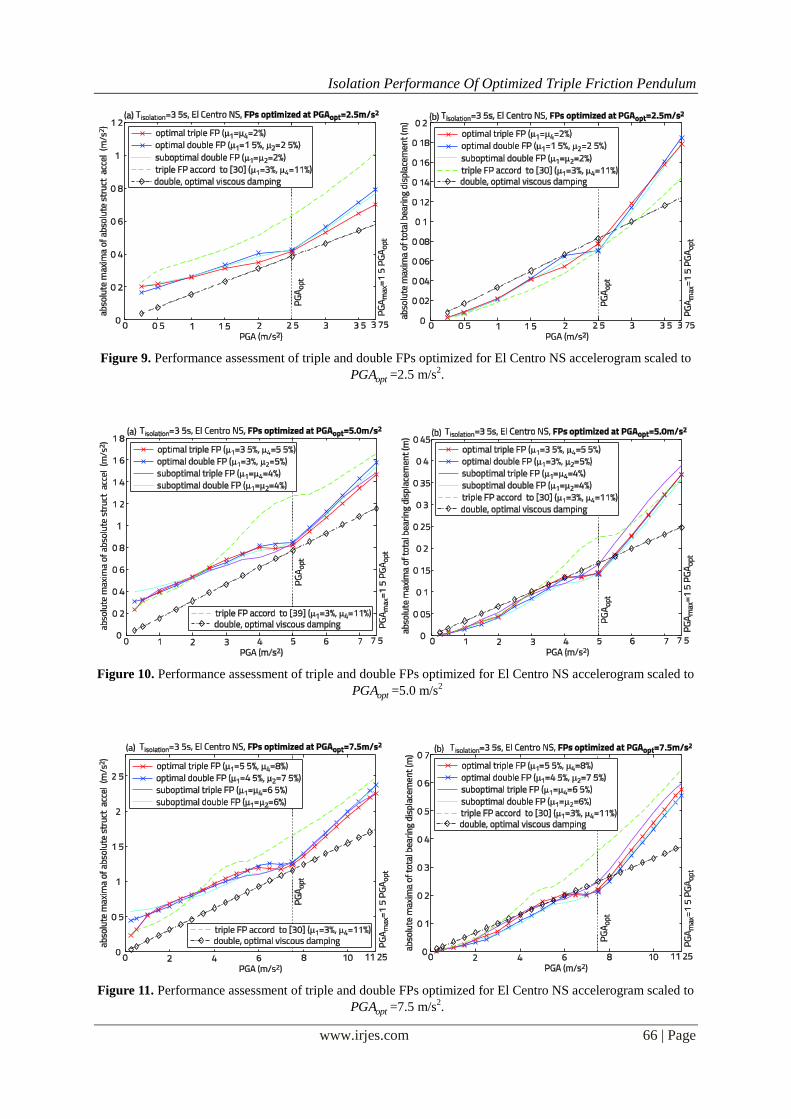
FP with 1 =3% and 4 =11% according to the design presented in [30]. For the Kobe, the Loma Prieta and the
Northridge earthquakes only the assessment results due to the triple and double FPs optimized at
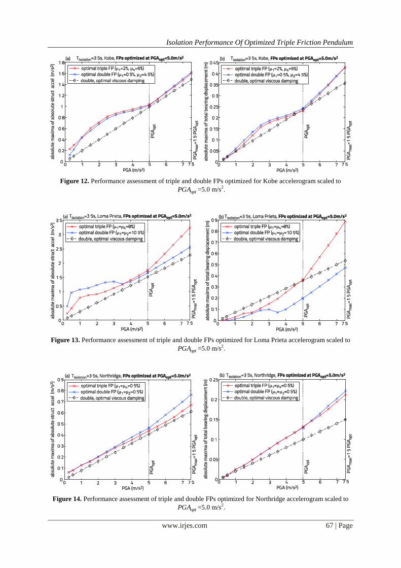
optPGA =5.0 m/s2 are depicted in Figs. 12 to 14 in order to limit the number of figures. The inspection of all
assessment results plotted in these figures shows:
For the El Centro NS, the Kobe and the Northridge earthquakes the isolation performances and total
bearing displacements due to optimal and suboptimal triple and double FPs are similar within the tested
PGA range.
Isolation Performance Of Optimized Triple Friction Pendulum
www.irjes.com 65 | Page
The results due to the Loma Prieta earthquake show that the optimized triple FP generates a better isolation
at optPGAPGA while the optimized double FP performs better at optPGAPGA . This result is caused
by the articulated slider assembly with low friction of 1.75% that improves the isolation at optPGAPGA
for the triple FP while the small friction of the slider assembly is too small to dissipate enough energy at
optPGAPGA where the double FP with higher friction coefficients (Tables 2 and 3) evokes better
isolation results.
The triple FP designed according to [30] with significantly different friction coefficients 1 and 4
performs significantly worse than the optimal and suboptimal triple and double FPs.
The comparison with the isolation performance of the pendulum with optimized linear viscous damping reveals:
Due to the nonlinear behaviours of the triple and double FPs these isolators can only be optimized at one
PGA.
The isolation performances of the triple and double FPs at optPGAPGA are slightly worse than that due
to optimal linear viscous damping because friction damping introduces higher frequency components into
the structure due to the instantaneous working behaviour of friction dampers as explained in [39, 40].
Optimal linear viscous damping generates PGA-independent isolation of the structure while the isolation
performance due friction damping worsens with increasing difference between the PGA value of
assessment and the PGA value of optimization.
The pendulum with optimal linear viscous damping does not only improve the isolation performance of the
structure at PGAs considerably smaller and larger than optPGA compared to both optimized FPs but also
results in significantly smaller maximum total bearing displacements.
VI. CONCLUSION Friction pendulums (FPs) are nonlinear devices due to their energy dissipation by friction damping. As
a result, these isolators can only be optimized for maximum isolation of the structure at one PGA value whereby
the isolation performance is suboptimal at smaller and larger PGAs. The aim of the triple FP is to improve this
drawback of passive FPs by its adaptive behaviour, i.e. stiffness and friction of the triple FP depend on the
actual bearing displacement and consequently on the PGA value.
In contrast to previous studies where the isolation performance of triple FPs were computed based on
the designs of the friction coefficients, effective radii and displacement capacities of the triple FP as published
this paper presents a new approach to assess the isolation performance of the triple FP. First, the triple FP is
optimized for minimum absolute structural acceleration, for realistic structural parameters and for the often
adopted isolation time period of 3.5 s. The optimization is based on two reasonable assumptions: 1) The design
of the articulated slider assembly is in agreement with the available literature and 2) sliding regime V that is not
intended to improve the isolation performance but to decrease the maximum bearing displacement capacity due
to earthquakes in the vicinity of the MCE is omitted whereby the optimization can be made without the highly
nonlinear impacts of restrainers 1 and 4. Due to these assumptions the triple FP can be optimized by variation of
the friction coefficients 1 and 4 of the primary sliding surfaces 1 and 4 only whereby the optimization problem
becomes numerically manageable. In addition, the optimization results can be plotted as three-dimensional
optimization surfaces which show qualitatively and quantitatively the sensitivity of the peak accelerations on the
friction tunings. The optimizations are performed for four real earthquakes that are scaled to three PGA values
whereby the triple FP is optimized for 12 different DBEs with different frequency contents and PGAs. In a
second stage the isolation performances of the optimized triple FPs are computed for the same earthquakes but
scaled to various PGAs ranging from very small values up to 150% of the PGA value at which the optimization
was made. As benchmark, the isolation performance of the optimized non-adaptive double FP is computed.
The results of demonstrate that the optimized triple and double FPs yield approx. the same isolation of
the structure at approx. the same total bearing displacement which is explained by the observation that the
optimal solutions of the triple FP and double FP are very similar.
ACKNOWLEDGEMENT The authors gratefully acknowledge the financial support of MAURER SE, Munich, Germany.
Isolation Performance Of Optimized Triple Friction Pendulum
www.irjes.com 66 | Page
Figure 9. Performance assessment of triple and double FPs optimized for El Centro NS accelerogram scaled to
optPGA =2.5 m/s2.
Figure 10. Performance assessment of triple and double FPs optimized for El Centro NS accelerogram scaled to
optPGA =5.0 m/s2
Figure 11. Performance assessment of triple and double FPs optimized for El Centro NS accelerogram scaled to
optPGA =7.5 m/s2.
Isolation Performance Of Optimized Triple Friction Pendulum
www.irjes.com 67 | Page
Figure 12. Performance assessment of triple and double FPs optimized for Kobe accelerogram scaled to
optPGA =5.0 m/s2.
Figure 13. Performance assessment of triple and double FPs optimized for Loma Prieta accelerogram scaled to
optPGA =5.0 m/s2.
Figure 14. Performance assessment of triple and double FPs optimized for Northridge accelerogram scaled to
optPGA =5.0 m/s2.
Isolation Performance Of Optimized Triple Friction Pendulum
www.irjes.com 68 | Page
REFERENCES
[1]. R.I. Skinner, W.H. Robinson, and G.H. McVerry, An introduction to seismic isolation (Wiley:
Chichester, England, 1993).
[2]. A.K. Chopra, Dynamics of Structures: Theory and Applications to Earthquake Engineering (Prentice-
Hall, 1995).
[3]. F. Naeim, and J.M. Kelly, Design of Seismic Isolated Structures (Wiley: New York, 1999).
[4]. C.A. Cornell, Engineering Seismic Risk Analysis, Bulletin of the Seismological Society of America,
58, 1968, 1583-1606.
[5]. M. Imbimbo, and J.M. Kelly, Stability aspects of elastomeric isolators, Earthquake Spectra, 13(3),
1997, 431-449.
[6]. V.A. Zayas, S.S. Low, and S.A. Mahin, The FPS earthquake resisting system experimental report,
Technical Report UBC/EERC-87/01, 1987.
[7]. T.M. Al-Hussaini, V.A. Zayas, and M.C. Constantinou, Seismic isolation of multi-story frame
structures using spherical sliding isolation systems, Technical Report NCEER-94-0007, 1994.
[8]. C.S Tsai, Finite element formulations for friction pendulum seismic isolation bearings, International
Journal for Numerical Methods in Engineering, 40, 1997, 29-49.
[9]. K.Z.Y. Yen, and Y.J. Lee, Passive vibration isolating system (US Patent No. 6126136, October 3,
2000).
[10]. Fenz, and M.C. Constantinou, Behaviour of the double concave Friction Pendulum bearing, Earthquake
Engng. Struct. Dyn., 35, 2006, 1403-1424.
[11]. C.S. Tsai, W.-S. Chen, T.-C. Chiang, and B.-J. Chen, Component and shaking table tests for full-scale
multiple friction pendulum system, Earthquake Engng. Struct. Dyn., 35, 2006, 1653-1675.
[12]. C. Bucher, Probability-based optimization of friction damping devices, Structural Safety, 31, 2009,
500-507.
[13]. R. Medeot, Experimental validation of re-centering capability evaluation based on energy concepts,
Proc. 14th
World Conference on Earthquake Engineering, October 12-17, 2008, Beijing, China.
[14]. J.M. Kelly, The role of damping in seismic isolation, Earthquake Engng. Struct. Dyn., 28(1), 1999, 3-
20.
[15]. J.F. Hall, Discussion of ‘The role of damping in seismic isolation’, Earthquake Engng. Struct. Dyn.,
28(12), 1999, 1717-1720.
[16]. Eurocode 8, Design of structures for earthquake resistance – Part 1: General rules, seismic actions and
rules for buildings (EN 1998-1:2004 + AC:2009).
[17]. M.Q. Feng, M. Shinozuka, and S. Fujii, Friction-controllable sliding isolation system, Journal of
Engineering Mechanics (ASCE), 119(9), 1993, 1845-1864.
[18]. N. Wongprasert, and M.D. Symans, Experimental evaluation of adaptive elastomeric base-isolated
structures using variable-orifice fluid dampers, Journal of Structural Engineering (ASCE), 131(6),
2005, 867-877.
[19]. T. Kobori, M. Takahashi, T. Nasu, and N. Niwa, Seismic response controlled structure with active
variable stiffness system, Earthquake Engng. Struct. Dyn., 22, 1993, 925-941.
[20]. S. Nagarajaiah, and S. Sahasrabudhe, Seismic response control of smart sliding isolated buildings using
variable stiffness systems: An experimental and numerical study, Earthquake Engng. Struct. Dyn.,
35(2), 2006, 177-197.
[21]. F. Casciati, L. Faravelli, and K. Hamdaoui, Performance of a base isolator with shape memory alloy
bars, Earthquake Engineering and Engineering Vibration, 6(4), 2007, 401-408.
[22]. N. Makris, Rigidity–plasticity–viscosity: Can electrorheological dampers protect base isolated
structures from near-source ground motions?, Earthquake Engng. Struct. Dyn., 26(5), 1997, 571-591.
[23]. J.C. Ramallo, E.A. Johnson, and B.F. Spencer Jr, ‘Smart’ base isolation systems, Journal of
Engineering Mechanics (ASCE), 128(10), 2002, 1088-1100.
[24]. P.Y. Lin, P.N. Roschke, C.H. Loh, and C.P. Cheng, Semi-active controlled base-isolation system with
magnetorheological damper and pendulum system, Proceedings of the 13th World Conference on
Earthquake Engineering, Vancouver, BC, Canada, 2004; Paper 691.
[25]. H. Li, and J. Ou, A design approach for semi-active and smart base-isolated buildings, Structural
Control and Health Monitoring, 13(2-3), 2006, 660-681.
[26]. F. Weber, and M. Maślanka, Precise Stiffness and Damping Emulation with MR Dampers and its
Application to Semi-active Tuned Mass Dampers of Wolgograd Bridge, Smart Mater. Struct., 23, 2014,
015019.
[27]. F. Weber, Robust force tracking control scheme for MR dampers, Struct. Control Health Monit.,
22(12), 2015, 1373-1395.
Isolation Performance Of Optimized Triple Friction Pendulum
www.irjes.com 69 | Page
[28]. A. Pocanschi, and M.C. Phocas, Earthquake isolator with progressive nonlinear deformability,
Engineering Structures, 29, 2007, 2586-2592.
[29]. D.M. Fenz, and M.C. Constantinou, Spherical sliding isolation bearings with adaptive behavior:
Theory, Earthquake Engng. Struct. Dyn., 37, 2008, 163-183.
[30]. D.M. Fenz, and M.C. Constantinou, Spherical sliding isolation bearings with adaptive behavior:
Experimental verification, Earthquake Engng. Struct. Dyn., 37, 2008, 185-205.
[31]. D.M. Fenz, and M.C. Constantinou, Modeling Triple Friction Pendulum Bearings for Response-
History Analysis, Earthquake Spectra, 24(4), 2008, 1011-1028.
[32]. F. Fadi, and M.C. Constantinou, Evaluation of simplified methods of analysis for structures with triple
friction pendulum isolators, Earthquake Engng. Struct. Dyn., 39, 2010, 5-22.
[33]. N.D. Dao, K.L. Ryan, E. Sato, and T. Sasaki, Predicting the displacement of Triple Pendulum bearings
in a full scale shaking experiment using a three-dimensional element, Earthquake Engng. Struct. Dyn.,
42, 2013, 1677-1695.
[34]. A.P. Giammona, K.L. Ryan, and N.D. Dao, Evaluation of Assumptions Used in Engineering Practice
to Model Buildings Isolated with Triple Pendulum Isolators in SAP2000, Earthquake Spectra, 31(2), ,
637-660.
[35]. C. Bucher, Analysis and Design of Sliding Isolation Pendulum Systems, Proc. IABSE Conference
Nara, May 13-15, 2015.
[36]. F. Weber, H. Distl, and C. Braun, Dynamic Characterization and Isolation Performance of Triple
Friction Pendulum, Proceedings of the 8th World Congress on Joints, Bearings and Seismic Systems
for Concrete Structures (IJBRC), Atlanta, Georgia, USA, September 25-29, 2016.
[37]. C.S. Tsai, T.-C. Chiang, and B.-J. Chen, Experimental evaluation of piecewise exact solution for
predicting seismic responses of spherical sliding type isolated structures, Earthquake Engng. Struct.
Dyn., 34, 2005, 1027-1046.
[38]. F. Al-Bender, V. Vincent Lampaert, and J. Swevers, The Generalized Maxwell-Slip Model: A Novel
Model for Friction Simulation and Compensation, IEEE Transactions on Automatic Control, 50(11),
2005, 1883-1887.
[39]. F. Weber, and C. Boston, Energy Based Optimization of Viscous-Friction Dampers on Cables, Smart
Mater. Struct., 19, 2010, 045025 (11pp).
[40]. F. Weber, J. Høgsberg, and S. Krenk, Optimal tuning of amplitude proportional Coulomb friction
damper for maximum cable damping, Journal of Structural Engineering, 136(2), 2010, 123-134.
[41]. A. Preumont, Vibration Control of Active Structures (Kluwer Academic Publishers, Dordrecht, 2002).