Embed Size (px)
Citation preview

International Journal of Engineering Research and General Science Volume 3, Issue 3, Part-2 , May-June, 2015 ISSN 2091-2730
246 www.ijergs.org
Analysis and Design of Doubly Fed Induction Generator for Wind Turbines
Using MATLAB
Mrs Aakansha Mercy Steele Assistant Professor Department of EX
UIT- RGPV, Bhopal [email protected]
ABSTRACT: This paper presents a grid-connected wind power generation scheme using Doubly Fed Induction Generator
(DFIG). This can supply power at constant voltage and constant frequency with the rotor speed varying. This makes it
suitable for variable speed wind energy application. The DFIG system consists of wind turbine, asynchronous wound rotor
induction generator, inverter and Pulse Width Modulation (PWM) controller. In which the stator is connected directly to the
grid and the rotor winding is in interface with rotor converter and grid converter. The use of back-to-back PWM converter in
the rotor circuit results in low distortion current, reactive power control and operate at variable speed. Mathematical
modelling of the DFIG is done in order to analyze the performance of the systems and they are simulated using MATLAB.
The simulation results for the two systems are obtained and hence it shows that the systems can operate at variable speed
with low harmonic current distortion. The objective is to track and extract maximum power from the wind energy system
and transfer it to the grid or useful work.
Keywords- Doubly Fed Induction Generator, Pulse Width Modulation, Mathematical modelling, Simulation, MATLAB
1. INTRODUCTION
Wind electrical power generation system has many potential benefits from both economical and environmental
perspectives. As it is cost–competitive, safe, clean and abundant renewable energy as compared to fossil fuel
(Nakra and Benoit, 1988; Z.Xie, et., 2007). The wind electrical power generator transforms mechanical energy
into electrical energy. The blades transfer the kinetic energy from the wind into rotational energy in the
transmission system and the generator is the next step in the supply of energy from the wind turbine to the
electrical grid.
There has been continuous change in the technology like from the fixed speed control system to the variable
speed control system. First the Self starting induction generators were used as they require generator to run in motor mode
at the start, so they are not self starting (Nakra and Benoit, 1988). For this purpose squirrel cage induction generator is
used because they are simple, serve the function of self starting, cheap and rugged. But they operate at constant speed and
in this system there is no inherent reactive power control method so it requires capacitor banks. Due to capacitor failure
use of synchronous generator in Wind Energy Conversion System (WECS) was used (Ammasaigounden. and Subbiah
1988; LeTang and Robert Zavadil, 1993). Which does not requires synchronization with the grid but all the above
generator operates at constant speed. So with the advancement in the thyristor converter the turbines can be used to
generator power at variable speed. In the control system converter- inverter circuit is use to control the magnitude, phase
and frequency. There are different ways to control the inverter and converter output power like fuzzy logic controller,
back-to back PWM converter in the rotor circuit of DFIG (M.Hussein, et., 1994; R.S.Pena, et., 1996). DC link chokes
were used but they are expensive and required an extra commutation circuit for operating at synchronous speed and this
result in the poor performance. It can be improved by the use of chopper but it produces current harmonics to overcome
this back draw Pulse Width Modulation (PWM) converter in asynchronous wound rotor induction generator also known

International Journal of Engineering Research and General Science Volume 3, Issue 3, Part-2 , May-June, 2015 ISSN 2091-2730
247 www.ijergs.org
as DFIG is used. It has low distortion of rotor, stator and supply current. It reduces the inverter cost. It can cover a wide
operation range from sub synchronous to super synchronous speed operating with the flow in both directions. So
maximum energy is capture from the wind and hence enables optimal speed tracking (R.S.Pena, et, 1996; Z.Xie, et.,
2007).
2. MATERIAL AND METHOD
In the DFIG the stator is directly connected to the grid and the rotor is connected to the variable frequency
converter (PWM) how to change the frequency, phase and magnitude of the rotor current or voltage is the main aim to
control the DFIG.
The wind turbine and the doubly-fed induction generator (WTDFIG) are shown in the Fig 1 called the Doubly-
Fed Induction Generator System. The AC/DC/AC converter is divided into two components: the rotor-side converter
(Crotor) and the grid-side converter (Cgrid). Crotor and Cgrid are Voltage-Sourced Converters which consist of forced-
commutated power electronic devices (IGBTs) to synthesize an AC voltage from a DC voltage source. The three-phase
rotor winding is connected to Crotor by slip rings and brushes and the three-phase stator winding is directly connected to
the grid. The power captured by the wind turbine is converted into electrical power by the induction generator and it is
transmitted to the grid by the stator and the rotor windings. The pulse width modulation controller system generates the
pitch angle command and the voltage command signals for Crotor and Cgrid respectively in order to control the power of the
wind turbine.
Fig. 1 Doubly-fed induction generator system
3. MATHEMATICAL MODELING OF SYSTEM

International Journal of Engineering Research and General Science Volume 3, Issue 3, Part-2 , May-June, 2015 ISSN 2091-2730
248 www.ijergs.org
Wind energy, doubly fed induction generator, rotor converter, grid converter, all are derived by mathematical model.
These mathematical models are used for the simulation purpose. Mathematical modelling of all system is given as
follows:
3.1 MAXIMAL POWER POINT TRACKING
The power that can be captured from the wind with a wind energy converter with effective area Ar is given by
( )
(1)
Where
( )
(2)
Where,
Turbine mechanical power.
Turbine performance coefficient.
Wind speed.
Turbine angular speed.
Air density.
Fig. 2 Relation curve of Pm and n

International Journal of Engineering Research and General Science Volume 3, Issue 3, Part-2 , May-June, 2015 ISSN 2091-2730
249 www.ijergs.org
So we can get the relation curve of mechanical power (Pm) and rotational speed (n) as shown in Fig.2 More
energy can be captured from wind by keeping the tip speed ratio to optimal constant. The speed of wind is regulated by
controlling the electromagnetic torque .The peak power depends on the turbine characteristic and air density ,the air
density may vary considerably over various season, which will not result in optimal tracking of the peak power point
under all condition ,there is a considerer able loss in output power energy, in order to restrain the concussion of the system
and to improve the tracking, a method of tracking the peak power is proposed which is independent of the turbine
parameters and air density (Z.Xie, et., 2007).
3.2 MODELLING OF DFIG
The following equations are derived for DFIG.
(3)
(4)
(5)
(6)
(7)
(8)
(9)
(10)
( ) (11)
Where,
usd d- axis stator voltage.
usq q-axis stator voltage.
urd d-axis rotor voltage.
urq q-axis rotor voltage.
sd d-axis stator flux linkage.

International Journal of Engineering Research and General Science Volume 3, Issue 3, Part-2 , May-June, 2015 ISSN 2091-2730
250 www.ijergs.org
sq q-axis stator flux linkage.
rd d-axis rotor flux linkage.
rq q-axis rotor flux linkage.
isd d-axis stator current.
isq q-axis stator current.
ird d-axis rotor current.
irq q-axis rotor current.
Rs Stator resistance.
Rr Rotor resistance.
s Synchronous angular speed.
sl Slip angular speed.
Ls Stator self- inductance.
Lr Rotor self- inductance.
Lm Mutual inductance.
p Pole pairs.
Te Electrical torque.
3.3 PULSE WIDTH MODULATION
The DC power at the rectifier output is filtered and converted to AC power using the PWM inverter employing
double edge sinusoidal modulation (R.S. Pena, et., 1996). PWM signals are used to switch the transistor in the inverter.
The output consists of sinusoidal modulated carrier pulses. Both the edges are modulated such that the average voltage
difference between any two of the output three phase are sinusoidal.
Mathematically represented by
x = Msin (x ) max (12)
Where,
International Journal of Engineering Research and General Science Volume 3, Issue 3, Part-2 , May-June, 2015 ISSN 2091-2730
251 www.ijergs.org
x = 1,2,3,4....................., 2r+1
Where,
M Modulation index range from 0 to1
X Edge being considered.
r Ratio of carrier to fundamental frequency in the inverter output.
x Angular displacement of the unmodulated edge.
x Maximum displacement of the edge for the chosen frequency ratio r.
4. PROPOSED TECHNIQUE OF DFIG
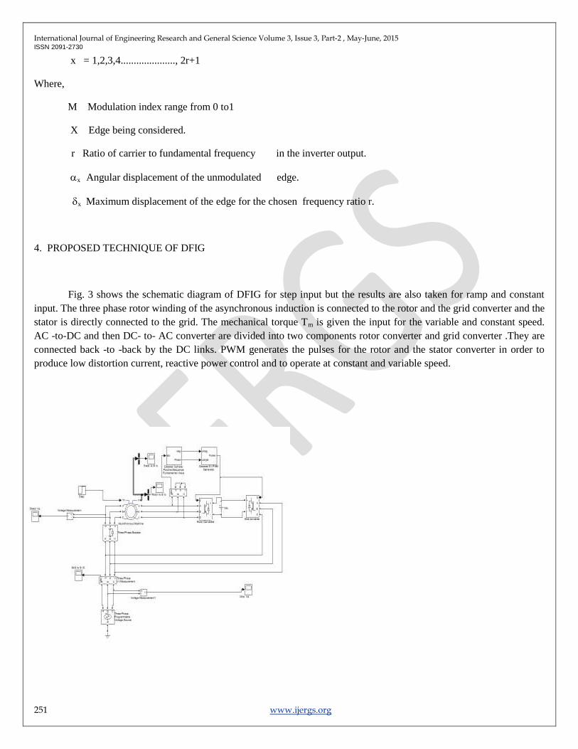
Fig. 3 shows the schematic diagram of DFIG for step input but the results are also taken for ramp and constant
input. The three phase rotor winding of the asynchronous induction is connected to the rotor and the grid converter and the
stator is directly connected to the grid. The mechanical torque Tm is given the input for the variable and constant speed.
AC -to-DC and then DC- to- AC converter are divided into two components rotor converter and grid converter .They are
connected back -to -back by the DC links. PWM generates the pulses for the rotor and the stator converter in order to
produce low distortion current, reactive power control and to operate at constant and variable speed.

International Journal of Engineering Research and General Science Volume 3, Issue 3, Part-2 , May-June, 2015 ISSN 2091-2730
252 www.ijergs.org
Fig. 3 Schematic diagram of DFIG
5. RESULTS AND DISCUSSIONS
The simulation results of doubly fed induction generator at constant speed and variable speed are shown using
MATLAB.
The results have been taken for different mechanical torque of the generator of 160 KW. As the wind speed varies with
time so the generator should operate at constant and variable speed. This shows the optimal tracking of power point under
all condition by varying the wind speed.
Fig. 4.1a to Fig. 4.5e shows the performance of DFIG. Fig. 4.1a shows the stator current waves. Fig. 4.2b shows
the stator voltage waves. Fig. 4.3c shows the grid current waves. Fig. 4.4d shows the grid voltage waves. Fig. 4.5e shows
the rotor current waves. For the variable speed the mechanical torque Tm is given by the step at the input the asynchronous
induction generator. The step value is from -1 to -4 and step time is 0.01sec. The stator current is 9.9 Amp, stator voltage
is 375Volts, grid current is 20 Amp, grid voltage is 350 Volts and rotor current is 7.9Amp.
Time in sec
Fig. 4.1a Wave form between stator current wrt time

International Journal of Engineering Research and General Science Volume 3, Issue 3, Part-2 , May-June, 2015 ISSN 2091-2730
253 www.ijergs.org
Time in sec
Fig. 4.2b Wave form between stator voltage wrt time
Time in sec
Fig. 4.3c Wave form between grid current wrt time

International Journal of Engineering Research and General Science Volume 3, Issue 3, Part-2 , May-June, 2015 ISSN 2091-2730
254 www.ijergs.org
Time in sec
Fig. 4.4d Wave form between grid voltage wrt time
Time in sec
Fig. 4.5e Wave form between rotor current wrt time
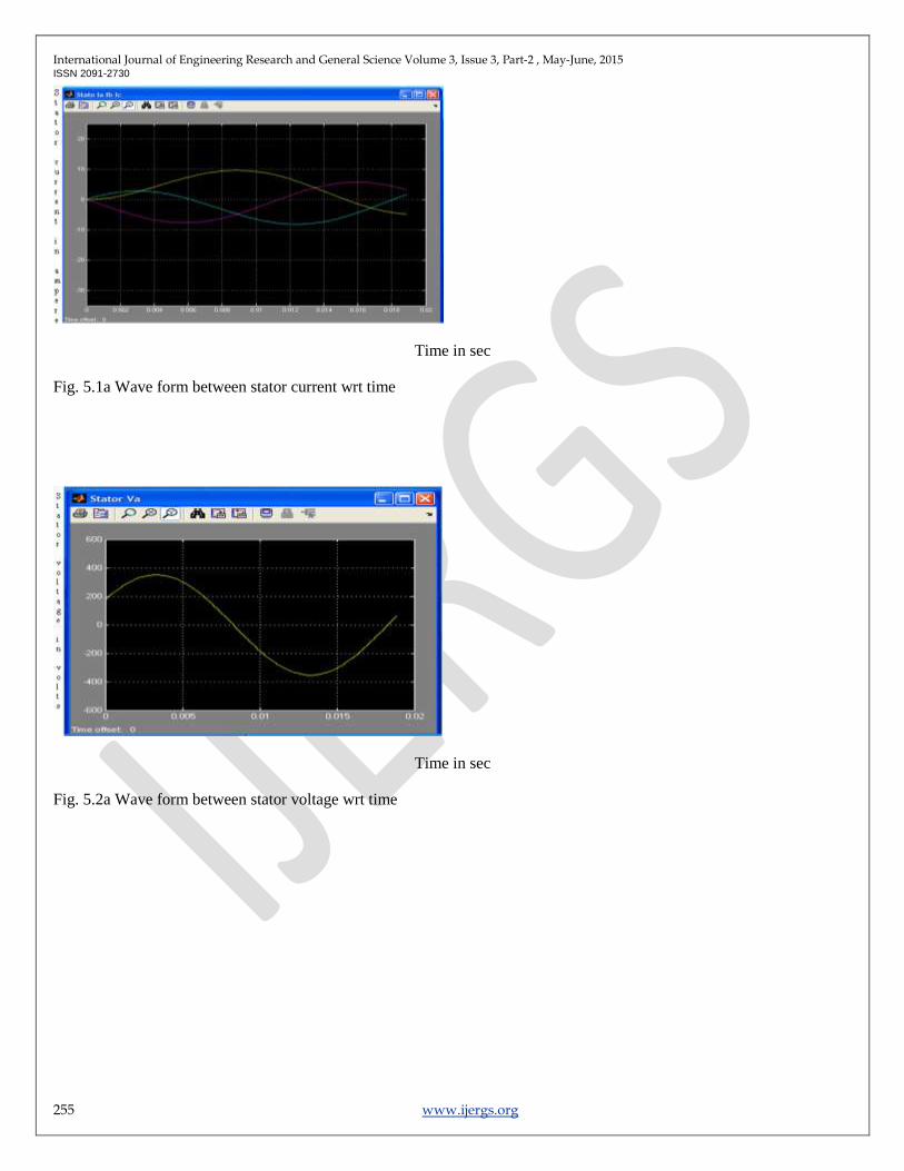
Fig. 5.1a to Fig. 5.5e shows the performance of DFIG. Fig. 5.1a shows the stator current waves. Fig. 5.2b shows
the stator voltage waves. Fig. 5.3c shows the grid current waves. Fig. 5.4d shows the grid voltage waves. Fig. 5.5e shows
the rotor current waves. For the variable speed the mechanical torque Tm is given by the ramp input of the asynchronous
induction generator. The ramp value is slope 1, start time 1.5sec and initial output -1. The stator current is 10 Amp, stator
voltage is 375Volts, grid current is 12.8 Amp, grid voltage is 350 Volts and rotor current is 7.5Amp.
International Journal of Engineering Research and General Science Volume 3, Issue 3, Part-2 , May-June, 2015 ISSN 2091-2730
255 www.ijergs.org
Time in sec
Fig. 5.1a Wave form between stator current wrt time
Time in sec
Fig. 5.2a Wave form between stator voltage wrt time

International Journal of Engineering Research and General Science Volume 3, Issue 3, Part-2 , May-June, 2015 ISSN 2091-2730
256 www.ijergs.org
Time in sec
Fig. 5.3c Wave form between grid current wrt time
Time in sec
Fig. 5.4d Wave form between grid current wrt time

International Journal of Engineering Research and General Science Volume 3, Issue 3, Part-2 , May-June, 2015 ISSN 2091-2730
257 www.ijergs.org
Time in sec
Fig. 5.5e Wave form between rotor current wrt time
Fig. 6.1a to Fig. 6.5e shows the performance of DFIG. Fig. 6.1a shows the stator current waves. Fig. 6.2b shows
the stator voltage waves. Fig. 6.3c shows the grid current waves. Fig. 6.4d shows the grid voltage waves. Fig. 6.5e shows
the rotor current waves. For the constant speed the mechanical torque Tm is given by the constant at the input of the
asynchronous induction generator. The constant value is -1. The stator current is 10 Amp, stator voltage is 375Volts, grid
current is 12.8 Amp, grid voltage is 350 Volts and rotor current is 7.5Amp.
Time in sec
Fig. 6.1a Wave form between stator current wrt time
Time in sec
Fig. 6.2bWave form between stator voltage wrt time

International Journal of Engineering Research and General Science Volume 3, Issue 3, Part-2 , May-June, 2015 ISSN 2091-2730
258 www.ijergs.org
Time in sec
Fig. 6.3c Wave form between grid current wrt time
Time in sec
Fig. 6.4d Wave form between grid voltage wrt time

International Journal of Engineering Research and General Science Volume 3, Issue 3, Part-2 , May-June, 2015 ISSN 2091-2730
259 www.ijergs.org
Time in sec
Fig. 6.5e Wave form between rotor current wrt time
In the DFIG system for constant speed and variable speed, the result shows the injection of current harmonics in
the grid current but the stator voltage, stator current, grid voltage and the rotor current are all sinusoidal with respect to
time. With the use of filter circuit in the DFIG system the current harmonics can be reduced.
CONCLUSION
Mathematical modelling of wind turbine, doubly fed induction generator and controller system is done. In order to
find out their performance in DFIG system they are simulated using MATLAB. The simulation results of the system are
show that it can operate at variable speed. As the wind speed changes from time to time due to change in temperature and
pressure. It rotates the rotor blade of the wind turbine at variable speed. So the wind power can be utilize at variable
speed. By the application of power electronics in the DFIG system, this can supply power at constant voltage and constant
frequency. While the rotor speeds varies due to variation in the wind speed. This makes it suitable for variable speed wind
energy application and hence this is useful in the maximum power tracking. The use of back-to-back PWM converter in
the rotor circuit of DFIG allows the bidirectional power flow between the stator and the rotor. This have the advantage of
reactive power control and low distortion currents operating at sub and super synchronous speed. The drawback of the
DFIG models is that they inject current harmonics in the grid current. However they can be reduced by the
implementation of the filter circuit. So further researches are going on to reduce the harmonics by improved PWM
schemes and filters. Utilization of wind energy from the offshore wind farms by the selection of reliable, maintenance fee
and robust generators.

International Journal of Engineering Research and General Science Volume 3, Issue 3, Part-2 , May-June, 2015 ISSN 2091-2730
260 www.ijergs.org
REFERENCES:
Nakra.H.L. and Benoit Dube (1988). “Slip Power Induction Generator for Large Vertical Axis Wind Turbines”, IEEE
Transaction on Energy Conversion, Vol.3.
Ammasaigounden.N and Subbiah.M (1988). “Chopper – Controller Wind-Driven Self – Excited Induction Generators”,
IEEE Transaction on Aerospace and Electronic System, Vol.2.
Cardirci.I and Ermis.M (1992). “Double- Output Induction Generators Operating at Sub synchronous and Super
synchronous Speeds: Steady-state Performance Optimisation and Wind-energy Recovery”, IEEE proceeding, Vol. 139.
LeTang and Robert Zavadil (1993). “Shunt Capacitor Failures due to Wind farm Induction Generators Self–Excitation
Phenomenon”, Tennessee USA, IEEE Energy conversion, Vol.8.
Hussein M. Mashaly, Adel M.Sharaf and Ahmed A.EL-Sattar Mohamed Mansour (1994). “A Fuzzy Logic Controller For
Wind Energy Utilization”, IEEE.
M.Godoy Simoes, Bimal K. Bose and Ronald J. Spiegel (1996). “Design and Performance Evaluation of a Fuzzy Logic
Based Variable Speed Wind Speed Wind Generator System”, IEEE.
Pena.R , Clare.J.C and Asher.G.M (1996). “A Doubly Fed Induction Generator Using Back-to- Back PWD Converters
and its Application to Variable Speed Wind Energy Conversion”, IEEE Proc – Electrical Power Appl, Vol.143.
Pena.R, Clare.J.C and Asher.G.M (1996). “A Doubly Fed Induction Generator Using Back-to- Back PWD Converters
Supplying an Isolated Load From a Variable Speed Wind Turbine”, IEEE Proc – Electrical Power Appl, Vol.143.
Robin M. Hilloowala and Adel M Sharaf (1996). “A Rule– Based Fuzzy Logic Controller for a PWM Inverter in a Stand
Alone Wind Energy Conversion Scheme”, IEEE Transaction on Industry Application, Vol. 321.
Pena. R.S, Asher.G.M, Clare.J.C and Cardenas.R (1996). “A Constant Frequency Constant Voltage Variable Speed Stand
Alone Wound Rotor Induction Generators”, England, International conference on Power Generation.

International Journal of Engineering Research and General Science Volume 3, Issue 3, Part-2 , May-June, 2015 ISSN 2091-2730
261 www.ijergs.org
Zhang.I and Wattanasarn.C (1998). “A Matrix Converter Excited Doubly-Fed Induction Machine as a Wind Power
Generator”, IEEE Conference Publication No.456.
Xie.Z,Zhang.C.W,ZhangX,Yang.S.Y and Cao R.X (2007). “Study on the Rotor Convertor of Doubly Fed Induction
Generators Used in Wind Turbine”, IEEE.
APPENDIX
Parameters of the DFIG model
Asynchronous (wound rotor) induction generator Power P 215Hp(160KW) Voltage
V 400V Frequency f 50Hz
Speed N 1487RPM Stator resistance Rs 0.01379 Rotor resistance Rs 0.007728
Stator self-inductance Ls
0.04755H Stator self-inductance Ls
Rotor self-inductance Lr 0.04775H Mutual inductance Lm 2.416 H