Embed Size (px)
Citation preview

Volume 3; Issue 1
Manuscript- 1
“DETERMINATION THE EFFECT OF CIRCULAR HOLE ON
THE STRESS CONCENTRATION FOR A PLATE SUBJECTED
TO UNIAXIAL AND BIAXIAL STRESSES IN TENSION AND
COMPRESSION STATUS”
www.ijmst.com February 2015
International Journal for Management Science
And Technology (IJMST)
ISSN: 2320-8848 (Online)
ISSN: 2321-0362 (Print)
Najah Rustum Mohsin
Mechanical Techniques Department,
Southern Technical University,
Technical Institute - Nasiriya,
Iraq
Younis Fakher Aoda
Mechanical Techniques Department,
Southern Technical University,
Technical Institute - Nasiriya,
Iraq
RaheemAbd Sayel
Mechanical Techniques Department,
Southern Technical University,
Technical Institute - Nasiriya,
Iraq

International Journal for Management Science and Technology (IJMST) Vol. 3; Issue 1
ISSN: 2320-8848(O.)/2321-0362(P.) Page 2 February, 2015
Abstract
This paper deals with investigation of applied stresses, plate length, plate width and the
diameter of the hole on the maximum stress for the plate with a one center hole and two holes
subjected to uniform uniaxial tension, uniaxial compression and biaxial tension stresses. The
maximum stresses are numerically calculated by finite element software ANSYS R.15 and
theoretically for different cases. The results show that the values of maximum stress in case
of uniaxial tension are greater than of biaxial tension and both of them greater than of
uniaxial compression. Furthermore, decreasing the applied stresses and hole diameter and
increasing the plate length and width lead to decreasing the value of maximum stresses.
KEY WORDS: Maximum stress, center hole, uniaxial tension, biaxial tension, uniaxial
compression, ANSYS R.15.
1. Introduction
Abrupt changes originated from irregularities in the distribution of stresses are known as
stress concentrators; these are presented for all types of stress, axial, bending or shear in the
presence of fillets, holes, grooves, keyways, splines, tool marks or accidental scrapes. The
inclusions or defects within the material over the surface also serve as "stress risers". The first
mathematical study on stress concentration was published shortly after 1900, with the aim of
working with other very simple different cases, experimental methods were developed to
measure local efforts. In recent years they have started using computer simulations based on
finite elements. Santos[1].
FEM is used by N. K. Jain [2] to study the distributions of stresses and deflection in
rectangular isotropic and orthotropic plates with central circular hole under transverse static
loading. S. P. Berlo [3] studied the effect of localized non-homogeneity in material property
on stress concentration. Two-dimensional infinite plane theory with both biaxial and uniaxial
far field loading was applied to problems with remote stress free holes, both circular and
elliptical. A. Santos [1] used ANSYS software to determine stress concentration factors in
flat plates with a central hole subjected to axial load. Effect of the geometry of hole on the
stress distribution around the hole was studied by D. Gunwant and J. P. Singh [4]. A
continuous elastic plate made up of steel with a central elliptical hole has been modeled and
descriptive with SOLID95 elements using ANSYS software. Zamanian et at. [5] were used
ABAQUS software to calculate the maximum stress for the SMC - R65 laminas with

International Journal for Management Science and Technology (IJMST) Vol. 3; Issue 1
ISSN: 2320-8848(O.)/2321-0362(P.) Page 3 February, 2015
circular/square hole under uniaxial loading. A comparison on stress concentration factor for
randomly oriented discontinuous fiber laminas between the results obtained with photo
elastic, Howland and Heywood formulations has been done for the plate with a circular
hole.M.Mirzagoltabarroshan [6] Used the ruling equation in mixed form by partial derivative
in fourth order, numerical approach with finite difference model and numerical approach with
ANSYS software to calculate the effect of hole and opening on stress concentration
phenomenon and its coefficient changes in plates and the shells. G. C. Mekalke et at. [7]
were used finite element method to study the effect of an initial stretching of a
rectangular plate with a cylindrical hole on the stress and displacement distributions around it
. They assumed that the initial stresses are caused by the uniformly stretching forces acting on
the 2 opposite ends. A. Khechaiet at. [8] were calculated the stress concentration factors in
cross-and-angle-ply laminated composite plates as well as in isotropic plates with single
circular holes subjected to uniaxial loading. A quadrilateral finite element of four-node with
32 degrees of freedom at each node are used to evaluate the stress distribution in laminated
composite plates with central circular holes. the transverse vibrations and the natural
frequencies of rectangular plate with circular central hole are investigated by K. Torabi and
A.R. Azadi [9] using Rayleigh-Ritz Method. The effect of the hole is taken into account by
subtracting the energies of the hole domain from the total energies of the whole plate. A. A.
Abd-Elhady [10] was studied the variations of stress and strain concentration factors for
plate with small central notch, circular notch and double U-notch subjected to uniaxial and
biaxial loading. The influence of the notch radius and plate thickness on the elastic stress and
strain concentration factors has been studied. Stress concentration factors at the root of an
elliptic hole in unidirectional functionally graded material plates under uniaxial and biaxial
loads are studied by T. A. Enab [11] using ANSYS Parametric Design Language (APDL) to
build the finite element models for the plates.
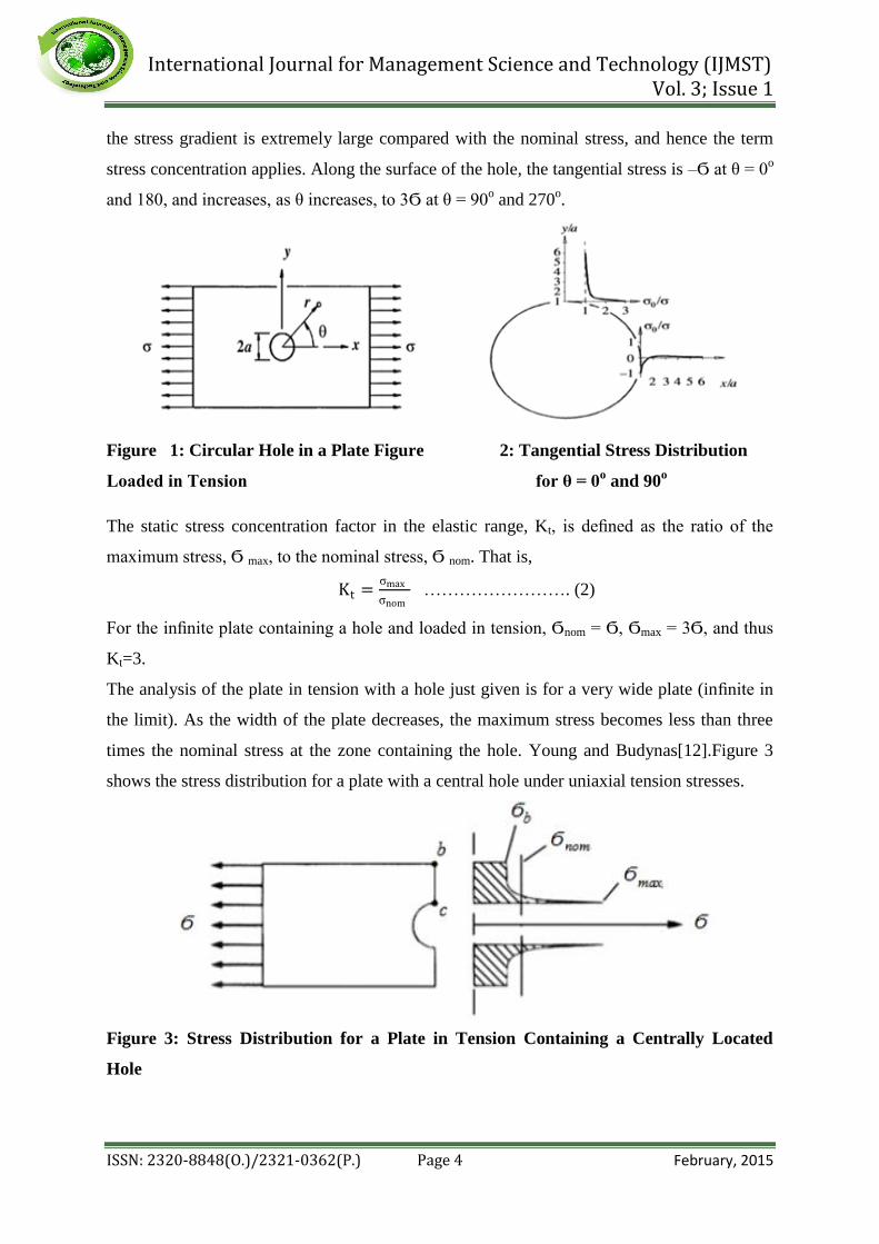
Consider the plate shown in Figure 1, loaded in tension by a force per unit area, consider that
the outer dimensions of the plate are infinite compared with the diameter of the hole, 2a. It
can be shown, from linear elasticity that the tangential stress throughout the plate is given by.
σθ =σ
2 1 +
a2
r2− 1 + 3
a4
r2 cos2θ ……………..…….. (1)
The maximum stress is Ϭ θ = 3Ϭ at r = a and θ = ±90o. Figure 2 shows how the tangential
stress varies along the x and y axes of the plate. For the top (and bottom) of the hole, we see
International Journal for Management Science and Technology (IJMST) Vol. 3; Issue 1
ISSN: 2320-8848(O.)/2321-0362(P.) Page 4 February, 2015
the stress gradient is extremely large compared with the nominal stress, and hence the term
stress concentration applies. Along the surface of the hole, the tangential stress is –Ϭ at θ = 0o
and 180, and increases, as θ increases, to 3Ϭ at θ = 90o and 270
o.
Figure 1: Circular Hole in a Plate Figure 2: Tangential Stress Distribution
Loaded in Tension for θ = 0o and 90
o
The static stress concentration factor in the elastic range, Kt, is defined as the ratio of the
maximum stress, Ϭ max, to the nominal stress, Ϭ nom. That is,
Kt =σmax
σnom ……………………. (2)
For the infinite plate containing a hole and loaded in tension, Ϭnom = Ϭ, Ϭmax = 3Ϭ, and thus
Kt=3.
The analysis of the plate in tension with a hole just given is for a very wide plate (infinite in
the limit). As the width of the plate decreases, the maximum stress becomes less than three
times the nominal stress at the zone containing the hole. Young and Budynas[12].Figure 3
shows the stress distribution for a plate with a central hole under uniaxial tension stresses.
Figure 3: Stress Distribution for a Plate in Tension Containing a Centrally Located
Hole

International Journal for Management Science and Technology (IJMST) Vol. 3; Issue 1
ISSN: 2320-8848(O.)/2321-0362(P.) Page 5 February, 2015
2. Materials and Methods
Circular hole in finite-width plate specimens subjected to uniform uniaxial and biaxial
stresses in tension and compression status as shown in Figures 4 a, b and c are studied to
determine the stress concentration using theoretical and numerical solutions
Figure 4: Circular Hole in Finite Width Specimens Subjected to
a) Uniform Uniaxial Tension b) Uniform Uniaxial Compression c) Uniform Biaxial
Tension
2.1 Specimens Material
The material of plate specimens is a Carbon steel with modulus of elasticity =202E-3
MN/m2, poison’s ratio = 0.292 and density = 7820 Kg/m3[13]. The models of ANSYS plate
specimens with elements, nodes and boundary conditions as shown in Figure5
Figure 5: ANSYS Models are used in the Solutions.

International Journal for Management Science and Technology (IJMST) Vol. 3; Issue 1
ISSN: 2320-8848(O.)/2321-0362(P.) Page 6 February, 2015
2.2 Theoretical Solution
Maximum stresses are calculated theoretically using the following formulas [12]
σnom = b
b−2a∗ σ ………………………………………. (3)
Kt = 3.00 − 3.13 2a
b + 3.66
2a
b
2
− 1.53 2a
b
3
……… (4)
σmax = σnom ∗ Kt …………………………..…………... (5)
2.3 Numerical Solution
Since the evolution of the term finite element by Clough in 1951, there have been significant
developments in finite element method. In this paper, Maximum stresses numerically
calculated using finite element software ANSYS R15 with Plane183 element as a
discretization element. Due to symmetry, only a quarter and half sectors of the plate is
modeled for case 1 and 2, respectively as shown in Table 1. Mesh generation is used for node
and element creation and the area around the hole is remodeled with a fine mesh.
2.4 Plane183 Element Description
PLANE183 is used in this paper as a discretization element. It is defined by 8 nodes ( I, J, K,
L, M, N, O, P when quadrilateral element) or 6 nodes ( I, J, K, L, M, N when triangle
element) having two degrees of freedom (UX , UY) at each node (translations in the nodal X
and Y directions). ANSYS help [14]. The geometry, node locations, and the coordinate
system for this element are shown in Figure6.
Figure 6: PLANE183 Element, ANSYS help [14]

International Journal for Management Science and Technology (IJMST) Vol. 3; Issue 1
ISSN: 2320-8848(O.)/2321-0362(P.) Page 7 February, 2015
2.5 The Studied Cases
Many cases (Table 1) are studied theoretically and numerically to explain the effect of
circular hole in a finite plate on the maximum stresses.
Table 1: The cases studied with Solutions, Parameters, ANSYS Models and Figures
Number

International Journal for Management Science and Technology (IJMST) Vol. 3; Issue 1
ISSN: 2320-8848(O.)/2321-0362(P.) Page 8 February, 2015
3. Results and Discussions
3.1 Theoretical and Numerical Compression
Figures 7-10 illustrate the numerical and theoretical variations of Ϭ max with different values
of Ϭ, l, b and 2a, respectively for the plate subjected to uniaxial tension. From these figures, it
can be seen that there are a small difference occurs between the two solutions with variation
of Ϭ and b while increasing 2a and decreasing l lead to increase the difference between the
two solutions.
Figure 7: Variation of maximum stress with Figure 8: Variation of maximum stress
applied uniaxial tension stress theoretically and with the length of plate theoretically
numerically and numerically
Figure 9: Variation of maximum stress with the Figure 10: Variation of maximum stress
width of plate theoretically and numerically with the hole diameter theoretically and
numerically
International Journal for Management Science and Technology (IJMST) Vol. 3; Issue 1
ISSN: 2320-8848(O.)/2321-0362(P.) Page 9 February, 2015
4. Numerical Solution
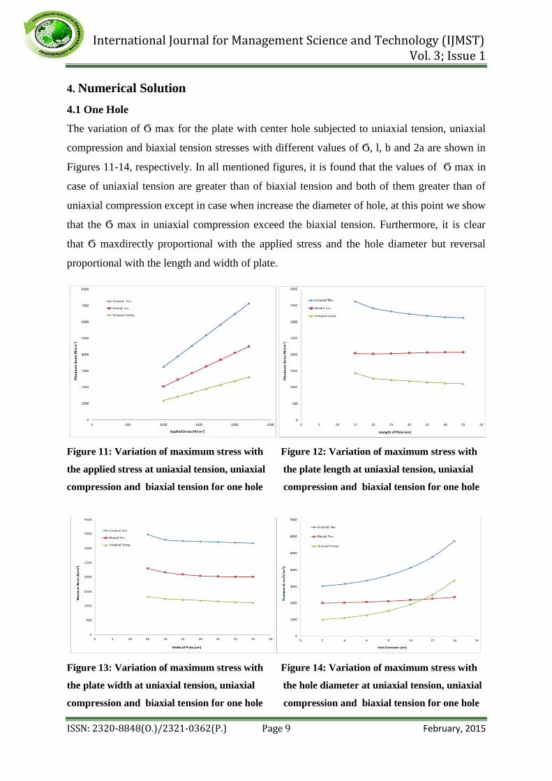
4.1 One Hole
The variation of Ϭ max for the plate with center hole subjected to uniaxial tension, uniaxial
compression and biaxial tension stresses with different values of Ϭ, l, b and 2a are shown in
Figures 11-14, respectively. In all mentioned figures, it is found that the values of Ϭ max in
case of uniaxial tension are greater than of biaxial tension and both of them greater than of
uniaxial compression except in case when increase the diameter of hole, at this point we show
that the Ϭ max in uniaxial compression exceed the biaxial tension. Furthermore, it is clear
that Ϭ maxdirectly proportional with the applied stress and the hole diameter but reversal
proportional with the length and width of plate.
Figure 11: Variation of maximum stress with Figure 12: Variation of maximum stress with
the applied stress at uniaxial tension, uniaxial the plate length at uniaxial tension, uniaxial
compression and biaxial tension for one hole compression and biaxial tension for one hole
Figure 13: Variation of maximum stress with Figure 14: Variation of maximum stress with
the plate width at uniaxial tension, uniaxial the hole diameter at uniaxial tension, uniaxial
compression and biaxial tension for one hole compression and biaxial tension for one hole
International Journal for Management Science and Technology (IJMST) Vol. 3; Issue 1
ISSN: 2320-8848(O.)/2321-0362(P.) Page 10 February, 2015
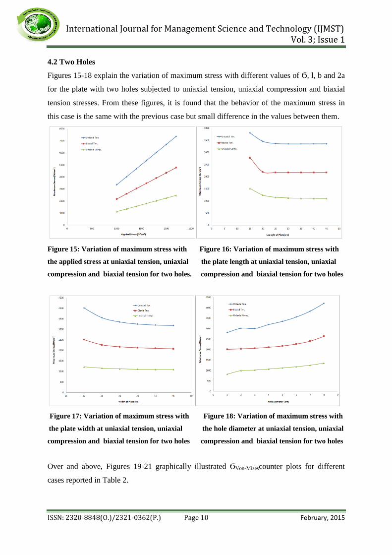
4.2 Two Holes
Figures 15-18 explain the variation of maximum stress with different values of Ϭ, l, b and 2a
for the plate with two holes subjected to uniaxial tension, uniaxial compression and biaxial
tension stresses. From these figures, it is found that the behavior of the maximum stress in
this case is the same with the previous case but small difference in the values between them.
Figure 15: Variation of maximum stress with Figure 16: Variation of maximum stress with
the applied stress at uniaxial tension, uniaxial the plate length at uniaxial tension, uniaxial
compression and biaxial tension for two holes. compression and biaxial tension for two holes
Figure 17: Variation of maximum stress with Figure 18: Variation of maximum stress with
the plate width at uniaxial tension, uniaxial the hole diameter at uniaxial tension, uniaxial
compression and biaxial tension for two holes compression and biaxial tension for two holes
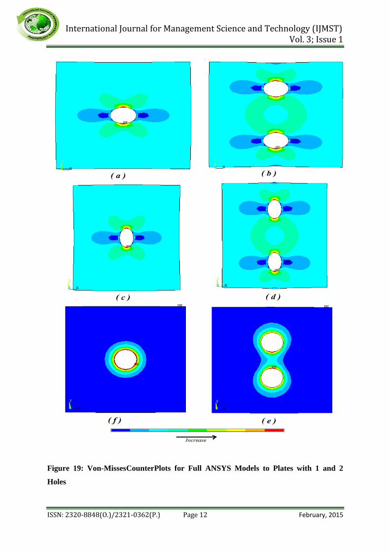
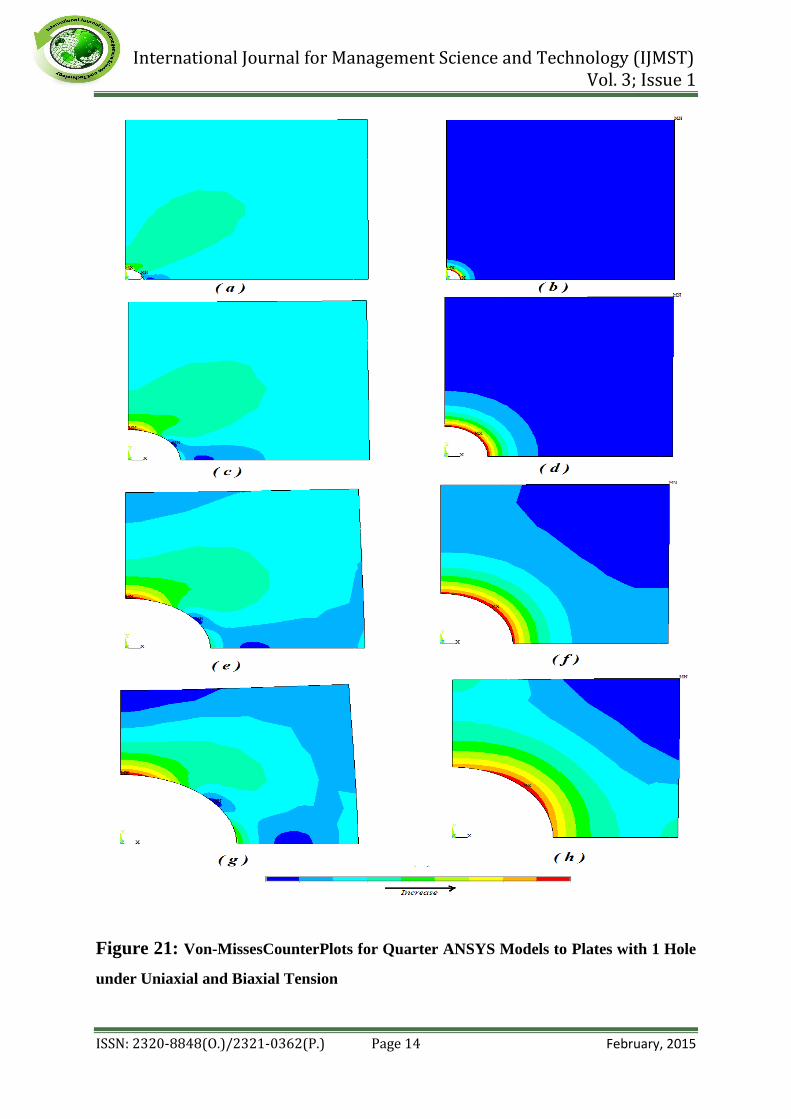
Over and above, Figures 19-21 graphically illustrated ϬVon-Misescounter plots for different
cases reported in Table 2.

International Journal for Management Science and Technology (IJMST) Vol. 3; Issue 1
ISSN: 2320-8848(O.)/2321-0362(P.) Page 11 February, 2015
Table 2: Figures number for Von-Misses Stresses Counter Plots with
ANSYS Models and Parameters
.
International Journal for Management Science and Technology (IJMST) Vol. 3; Issue 1
ISSN: 2320-8848(O.)/2321-0362(P.) Page 12 February, 2015
Figure 19: Von-MissesCounterPlots for Full ANSYS Models to Plates with 1 and 2
Holes

International Journal for Management Science and Technology (IJMST) Vol. 3; Issue 1
ISSN: 2320-8848(O.)/2321-0362(P.) Page 13 February, 2015
Figure 20: Von-MissesCounterPlots for Quarter and Half ANSYS Models to Plates with
1 and 2 Holes
International Journal for Management Science and Technology (IJMST) Vol. 3; Issue 1
ISSN: 2320-8848(O.)/2321-0362(P.) Page 14 February, 2015
Figure 21: Von-MissesCounterPlots for Quarter ANSYS Models to Plates with 1 Hole
under Uniaxial and Biaxial Tension

International Journal for Management Science and Technology (IJMST) Vol. 3; Issue 1
ISSN: 2320-8848(O.)/2321-0362(P.) Page 15 February, 2015
5. Conclusion
The main conclusions of this work are reported below
1. The values of maximum stress in case of uniaxial tension are greater than of biaxial
tension and both of them greater than of uniaxial compression.
2. Increasing the applied stresses and hole diameter and decreasing the plate length and
width lead to increasing the value of maximum stresses.
3. The behaviour of the maximum stress for plates with one center hole is the same with
the plates with two holes but there is a sensitive difference in the values between them.
International Journal for Management Science and Technology (IJMST) Vol. 3; Issue 1
ISSN: 2320-8848(O.)/2321-0362(P.) Page 16 February, 2015
References
A. Santos. Determination of stress concentration factors on flat plates of structural steel.
Journal of Physics,2nd International Meeting for Researchers in Materials and Plasma
Technology, Conference Series 466, 2013.
N. K. Jain. Analysis of Stress Concentration and Deflection in Isotropic and Orthotropic
RectangularPlates with Central Circular Hole under Transverse Static Loading. World
Academy of Science, Engineering and Technology,
http://citeseerx.ist.psu.edu/viewdoc/download?doi=10.1.1.193.4173&rep=rep1&type=pdf
, pp. 446-452, 2009.
S. P. Berlo. Stress Concentration Effects in Highly Localized Functionally Graded
Materials. MSc theses, 2009.
D. Gunwant and J. P. Singh.Stress and Displacement Analysis of a Rectangular Plate with
Central Elliptical Hole.International Journal of Engineering and Innovative Technology
(IJEIT), Volume 3(3), pp., 2013.
H. Zamanian,B. Marzban, P. Bagheri and M. Gudarzi. On Stress Concentration Factor for
Randomly Oriented Discontinuous Fiber Laminas with Circular/Square Hole. Journal of
Science and Engineering, Vol. 3(1), pp. 7-18, 2013.
M.Mirzagoltabarroshan.Studying Decreased Methods of Stress Concentration around
Holes and Openings of Plate and Shell Structures’ Body. International Research Journal
of Applied and Basic Sciences, Vol. 5(8), pp. 1008-1015, 2013.
G. C. Mekalke, M. V. Kavade and S. S. Deshpande. Analysis of a Plate with a circular
Hole by FEM. IOSR Journal of Mechanical and Civil Engineering (IOSR-JMCE),Second
International Conference on Emerging Trends in engineering (SICETE), Vol. 1, PP. 25-
30, 2013.
A. Khechai,A. Tati and A. Guettala.Finite element analysis of stress concentrations and
failure criteria in composite plates with circular holes.Frontiers of Mechanical
Engineering journal, Vol. 9(3), pp. 281-294, 2014.
K. Torabi and A.R. Azadi.Vibration Analysis for Rectangular Plate Having a Circular
Central Hole with Point Support by Rayleigh-Ritz Method. Journal of Solid Mechanics,
Vol. 6(1), pp. 28-42, 2014.
A. A. Abd-Elhady. 3-D Finite Element Analysis of Plate with Small Notch Subjected to
Biaxial Loading.Emirates Journal for Engineering Research, Vol. 19(1), pp. 27- 35, 2014.

International Journal for Management Science and Technology (IJMST) Vol. 3; Issue 1
ISSN: 2320-8848(O.)/2321-0362(P.) Page 17 February, 2015
T. A. Enab. Stress concentration analysis in functionally graded plates with elliptic holes
under biaxial loadings.Ain Shams Engineering Journal, Volume 5(3), pp. 839–850, 2014.
W. C. Young and R. G. Budynas. Roark’s Formulas for Stress and Strain.McGraw-Hill
companies, Seventh Edition, 2002.
S. G. Kulkarni. MachineDesign. McGraw-Hill companies, Sixth reprint, New Delhi,
2012.
ANSYS help.

![ISSN: 2320-8848 (Online) ISSN: 2321-0362 (Print ...€¦ · local community by diesel generators. However, diesel generators cause significant impacts on the environment. [2]. Due](https://img.pdfslide.net/doc/110x75/5e7bc75bc11341180c2e0c85/issn-2320-8848-online-issn-2321-0362-print-local-community-by-diesel-generators.jpg)