Embed Size (px)
Citation preview
ITTGoulds PumpsG&L SERIES MODELS 3642/3742Installation, Operation and Maintenance Instructions
Goulds Pumps is a brand of ITT Residential and Commercial Water.
www.goulds.com
Engineered for life
Commercial Water
�
SUBJECT PAGESafety Instructions ......................................................................................................................................................... 3Description and Specifications ....................................................................................................................................... 3Engineering Data ........................................................................................................................................................... 3Installation Location .................................................................................................................................................................... 3 Foundation ................................................................................................................................................................ 3 Frame-Mounted ......................................................................................................................................................... 3Piping Suction ...................................................................................................................................................................... 4 Discharge ................................................................................................................................................................... 4Wiring and Grounding .................................................................................................................................................. 4Coupling Alignment ...................................................................................................................................................... 4Rotation ........................................................................................................................................................................ 5Operation ...................................................................................................................................................................... 5Maintenance.................................................................................................................................................................. 5Disassembly Liquid End ................................................................................................................................................................. 6 Bearing Frame ............................................................................................................................................................ 6Reassembly Bearing Frame ............................................................................................................................................................ 6 Liquid End ................................................................................................................................................................. 6Repair Parts ................................................................................................................................................................... 7Troubleshooting ............................................................................................................................................................ 8Limited Warranty .......................................................................................................................................................... 8Declaration of Conformity .......................................................................................................................................... �9
MODELS 3642 3742 1x1¼-5 1x1¼-5 1¼x1½-5 1¼x1½-5
Pump Model Number:
Pump Serial Number:
Dealer:
Dealer Phone No.:
Date of Purchase:
Date of Installation:
Current Readings at Startup:
1 Ø 3 Ø L1-� L�-3 L3-1
Amps: Amps:
Volts: Volts:
3
StartsperHour:20-Evenlydistributed
INSTALLATION
Location:
Locatepumpasnearliquidsourceaspractical;belowlevelofliquidforreprimingcapability.
Allowadequatespaceforservicingandventilation.Protecttheunitfromweatherandwaterdamageduetorain,floodingorfreezingtemperatures.
Close - Coupled Units
Unitsmaybeinstalledhorizontally,inclinedorverti-callywiththemotorabovethepump.
NOTICE: DO NOT INSTALL WITH MOTOR BELOW PUMP. ANY LEAKAGE OR CONDENSATION WILL AFFECT THE MOTOR.
Foundation:
AflatandsubstantialfoundationsurfaceMUST beprovidedtoavoiddistortionand/orstrainwhentighteningthefoundationbolts.Arubbermountingisacceptabletoreducenoiseorexcessivevibration.
Tightenmotorhold-downboltsBEFORE connectingpipingtopump.
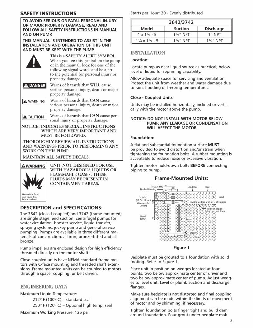
Frame-Mounted Units:
Figure 1
Bedplatemustbegroutedtoafoundationwithsolidfooting.RefertoFigure1.
Placeunitinpositiononwedgeslocatedatfourpoints,twobelowapproximatecenterofdriverandtwobelowapproximatecenterofpump.Adjustwedg-estolevelunit.Levelorplumbsuctionanddischargeflanges.
Makesurebedplateisnotdistortedandfinalcouplingalignmentcanbemadewithinthelimitsofmovementofmotorandbyshimming,ifnecessary.
Tightenfoundationboltsfingertightandbuilddamaroundfoundation.Pourgroutunderbedplatemak-
SAFETY INSTRUCTIONS TO AVOID SERIOUS OR FATAL PERSONAL INJURY OR MAJOR PROPERTY DAMAGE, READ AND FOLLOW ALL SAFETY INSTRUCTIONS IN MANUAL AND ON PUMP.THIS MANUAL IS INTENDED TO ASSIST IN THE INSTALLATION AND OPERATION OF THIS UNIT AND MUST BE KEPT WITH THE PUMP.
This is a SAFETY ALERT SYMBOL. When you see this symbol on the pump or in the manual, look for one of the following signal words and be alert to the potential for personal injury or property damage.Warns of hazards that WILL cause serious personal injury, death or major property damage.Warns of hazards that CAN cause serious personal injury, death or major property damage.Warns of hazards that CAN cause per-sonal injury or property damage.
NOTICE: INDICATES SPECIAL INSTRUCTIONS WHICH ARE VERY IMPORTANT AND MUST BE FOLLOWED.
THOROUGHLY REVIEW ALL INSTRUCTIONS AND WARNINGS PRIOR TO PERFORMING ANY WORK ON THIS PUMP.MAINTAIN ALL SAFETY DECALS.
UNIT NOT DESIGNED FOR USE WITH HAZARDOUS LIQUIDS OR FLAMMABLE GASES. THESE FLUIDS MAY BE PRESENT IN CONTAINMENT AREAS.
DESCRIPTION and SPECIFICATIONS:The3642(closed-coupled)and3742(frame-mounted)aresinglestage,endsuction,centrifugalpumpsforwatercirculation,boosterservice,liquidtransfer,sprayingsystems,jockeypumpandgeneralservicepumping.Pumpsareavailableinthreedifferentma-terialsofconstruction:alliron,bronze-fittedandallbronze.
Pumpimpellersareencloseddesignforhighefficiency,threadeddirectlyonthemotorshaft.
Close-coupledunitshaveNEMAstandardframemo-torswithC-facemountingandthreadedshaftexten-sions.Framemountedunitscanbecoupledtomotorsthroughaspacercoupling,orbeltdriven.
ENGINEERING DATA
MaximumLiquidTemperature: 212ºF(100ºC)–standardseal 250ºF(120ºC)–Optionalhightemp.seal
MaximumWorkingPressure:125psi
3642/3742 Model Suction Discharge 1x1¼-5 1¼”NPT 1”NPT 1¼x1½-5 1½”NPT 1¼”NPT
DANGER
WARNING
CAUTION
WARNING
Hazardousfluidscancausefire,burnsordeath.
Sleeve
Washer
Lug
Top of foundation –clean and wet down
Grout
Leveling wedges or shims – left in place
BaseGrout Hole1⁄4”(6.35 mm)Finished Grouting
1⁄2 to 3⁄4”(12.7 to 19 mm)Allowance for
Leveling
WoodFrame
4
WIRING AND GROUNDING
Install,groundandwireaccord-ingtolocalandNationalElectri-calCodeRequirements.
Installanalllegdisconnectswitchnearthepump.
Disconnectandlockoutelectri-calpowerbeforeinstallingorservicingthepump.
ElectricalsupplyMUST matchpump’sname-platespecifications.Incorrectvoltagecancausefire,damagetothemotorandvoidsthewar-ranty.
MotorsnotprotectedMUST beprovidedwithcontactorsandthermaloverloadsforsinglephasemotors,orstarterswithheatersforthreephasemotors.Seemotornameplate.
Useonlycopperwiretomotorandground.ThegroundwireMUST beatleastaslargeasthewiretothemotor.Wiresshouldbecolorcodedforeaseofmaintenance.
Followmotormanufacturer’swiringdiagramonthemotornameplateorterminalcovercarefully.
FAILURE TO PERMANENTLY GROUND THE PUMP, MOTOR AND CONTROLS BEFORE CONNECTING TO ELECTRICAL POWER CAN CAUSE SHOCK, BURNS OR DEATH.
COUPLING ALIGNMENT
FAILURE TO DISCONNECT AND LOCKOUT ELECTRICAL POWER BEFORE ATTEMPTING ANY MAINTENANCE CAN CAUSE SEVERE PERSONAL INJURY.
ingsuretheareasunderthepumpandmotorfeetarefilledsolid.Allowgrouttoharden48hoursbeforefullytighteningfoundationbolts.
Tightenpumpandmotorhold-downboltsbeforealigningshaftorconnectingthepipingtopump.
PIPING
Pipingshouldbenosmallerthanpump’sdischargeandsuctionconnectionsandkeptasshortaspossible,avoidingunnecessaryfittingstominimizefrictionlosses.
AllpipingMUST beindependentlysupportedandMUST NOTplaceanypipingloadsonthepump
NOTICE: DO NOT FORCE PIPING INTO PLACE AT PUMP SUCTION AND DISCHARGE CONNECTIONS.
AllpipejointsMUST beairtight.
Piping – Suction
Forsuctionliftsover15ft.(4.6m),consultpumpper-formancecurvefornetpositivesuctionheadrequired(NPSHR).
Ifapipesizelargerthanpumpsuctionisrequired,aneccentricpipereducer,withthestraightsideup,MUST beinstalledatthepumpsuction.
Ifpumpisinstalledbelowtheliquidsource,installagatevalveinthesuctionforpumpinspectionandmaintenance.
NOTICE: DO NOT USE THE GATE VALVE TO THROTTLE PUMP. THIS MAY CAUSE LOSS OF PRIME, EXCESSIVE TEMPERATURES AND DAMAGE TO PUMP, VOIDING WARRANTY.
Ifthepumpisinstalledabovetheliquidsource,thefollowingMUST beprovided:
Toavoidairpockets,nopartofthepipingshouldbeabovethepumpsuctionconnection.
Slopethepipingupwardfromliquidsource.
UseafootvalveorcheckvalveONLY ifnecessaryforprimingortoholdprimeduringintermittentduty.
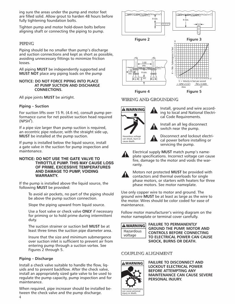
ThesuctionstrainerorsuctionbellMUST beatleastthreetimesthesuctionpipediameterarea.
Insurethatthesizeandminimumsubmergenceoversuctioninletissufficienttopreventairfromenteringpumpthroughasuctionvortex.SeeFigures2through5.
Piping – Discharge
Installacheckvalvesuitabletohandletheflow,liq-uidsandtopreventbackflow.Afterthecheckvalve,installanappropriatelysizedgatevalvetobeusedtoregulatethepumpcapacity,pumpinspectionandformaintenance.
Whenrequired,pipeincreasershouldbeinstalledbe-tweenthecheckvalveandthepumpdischarge.
Figure 4 Figure 5
H min.
D D
H min.
D D
1.5Dmin.
3.0Dmin.
H min.
D min.2
16151413121110
987654321
H =
Min
. Sub
mer
genc
e in
feet
H
1 2 3 4 5 6 7 8 9 10111213141516 VV = Velocity in feet per second
= GPM x 0.321Area
PM x 0.4085D2
Figure 2 Figure 3
WARNING
Hazardousvoltagecanshock,burnorcausedeath.
WARNINGHazardousvoltage
Hazardousmachinerycancausepersonalinjuryordeath.
WARNING
5
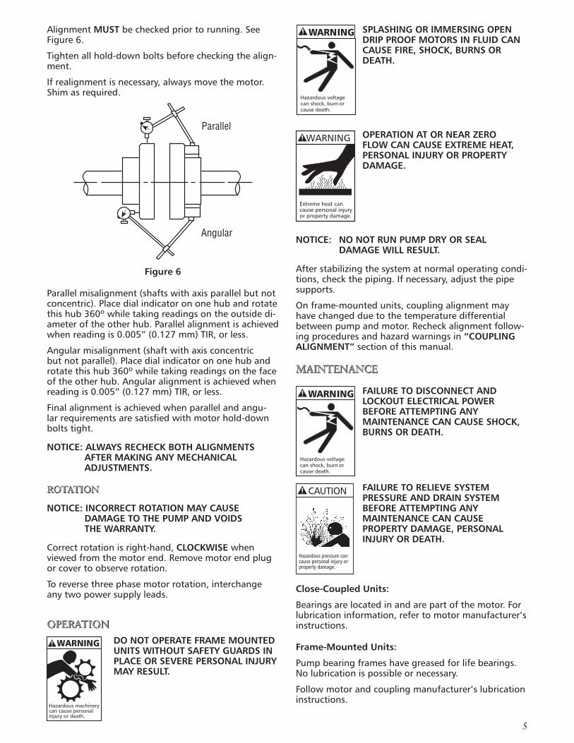
AlignmentMUST becheckedpriortorunning.SeeFigure6.
Tightenallhold-downboltsbeforecheckingthealign-ment.
Ifrealignmentisnecessary,alwaysmovethemotor.Shimasrequired.
Figure 6
Parallelmisalignment(shaftswithaxisparallelbutnotconcentric).Placedialindicatorononehubandrotatethishub360ºwhiletakingreadingsontheoutsidedi-ameteroftheotherhub.Parallelalignmentisachievedwhenreadingis0.005”(0.127mm)TIR,orless.
Angularmisalignment(shaftwithaxisconcentricbutnotparallel).Placedialindicatorononehubandrotatethishub360ºwhiletakingreadingsonthefaceoftheotherhub.Angularalignmentisachievedwhenreadingis0.005”(0.127mm)TIR,orless.
Finalalignmentisachievedwhenparallelandangu-larrequirementsaresatisfiedwithmotorhold-downboltstight.
NOTICE: ALWAYS RECHECK BOTH ALIGNMENTS AFTER MAKING ANY MECHANICAL ADJUSTMENTS.
ROTATION
NOTICE: INCORRECT ROTATION MAY CAUSE DAMAGE TO THE PUMP AND VOIDS THE WARRANTY.
Correctrotationisright-hand,CLOCKWISE whenviewedfromthemotorend.Removemotorendplugorcovertoobserverotation.
Toreversethreephasemotorrotation,interchangeanytwopowersupplyleads.
OPERATION
DO NOT OPERATE FRAME MOUNTED UNITS WITHOUT SAFETY GUARDS IN PLACE OR SEVERE PERSONAL INJURY MAY RESULT.
SPLASHING OR IMMERSING OPEN DRIP PROOF MOTORS IN FLUID CAN CAUSE FIRE, SHOCK, BURNS OR DEATH.
OPERATION AT OR NEAR ZERO FLOW CAN CAUSE EXTREME HEAT, PERSONAL INJURY OR PROPERTY DAMAGE.
NOTICE: NO NOT RUN PUMP DRY OR SEAL DAMAGE WILL RESULT.
Afterstabilizingthesystematnormaloperatingcondi-tions,checkthepiping.Ifnecessary,adjustthepipesupports.
Onframe-mountedunits,couplingalignmentmayhavechangedduetothetemperaturedifferentialbetweenpumpandmotor.Recheckalignmentfollow-ingproceduresandhazardwarningsin“COUPLING ALIGNMENT”sectionofthismanual.
MAINTENANCE
FAILURE TO DISCONNECT AND LOCKOUT ELECTRICAL POWER BEFORE ATTEMPTING ANY MAINTENANCE CAN CAUSE SHOCK, BURNS OR DEATH.
FAILURE TO RELIEVE SYSTEM PRESSURE AND DRAIN SYSTEM BEFORE ATTEMPTING ANY MAINTENANCE CAN CAUSE PROPERTY DAMAGE, PERSONAL INJURY OR DEATH.
Close-Coupled Units:
Bearingsarelocatedinandarepartofthemotor.Forlubricationinformation,refertomotormanufacturer’sinstructions.
Frame-Mounted Units:
Pumpbearingframeshavegreasedforlifebearings.Nolubricationispossibleornecessary.
Followmotorandcouplingmanufacturer’slubricationinstructions.
WARNING
Hazardousvoltagecanshock,burnorcausedeath.
Extremeheatcancausepersonalinjuryorpropertydamage.
WARNING
WARNING
Hazardousvoltagecanshock,burnorcausedeath.
Hazardous pressure cancause personal injury orproperty damage.
CAUTION
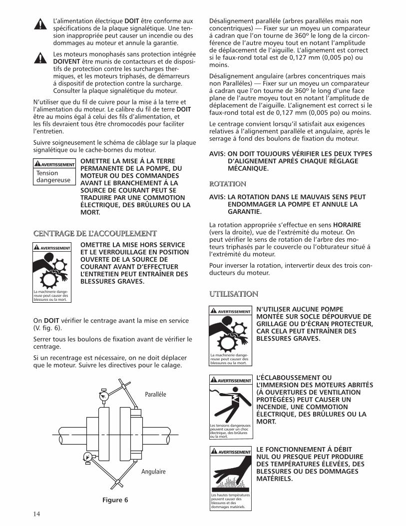
Parallel
Angular
Hazardousmachinerycancausepersonalinjuryordeath.
WARNING
6
Seasonal Service:
ToREMOVE pumpfromservice,removedrainpluganddrainallunprotectedpiping.
ToRETURN pumptoservice,replacedrainplugusingTeflon™tapeorequivalent.
Reconnectsuctionlineifremoved,examineunionandrepairifnecessary.
Referto“OPERATION”sectionofmanual.
DISASSEMBLY
FollowALLwarningsandinstructionsinthe“MAINTE-NANCE”sectionofthismanual.
Close-coupled units:Removemotorhold-downbolts.
Frame-mounted units:Removecouplingguard,spacer,couplingandframehold-downbolts.
Liquid End:
1. Removecasingbolts(370).
2.Removebackpull-outassemblyfromcasing(100).
3.Removecasinggasket(351).Discard.
4.Onclose-coupledunits,removemotorendplugorcovertoexposescrewdriverslotorflatsonendofmotorshaft.
5.Whilerestrainingshaftwithanappropriatetool(close-coupledunits)orwithastrapwrench(frame-mountedunits)removeimpellernut(304)byturningCOUNTERCLOCKWISE.Impellernutmayneedtobeheatedwithtorchtoremove.
NOTICE: EXERCISE CAUTION WHEN HANDLING HOT IMPELLER NUT.
6.Whilerestrainingshaft,removeimpeller(101)byturningCOUNTERCLOCKWISE.Impellermayneedtobeheatedtoremove.
NOTICE: EXERCISE CAUTION WHEN HANDLING HOT IMPELLER.
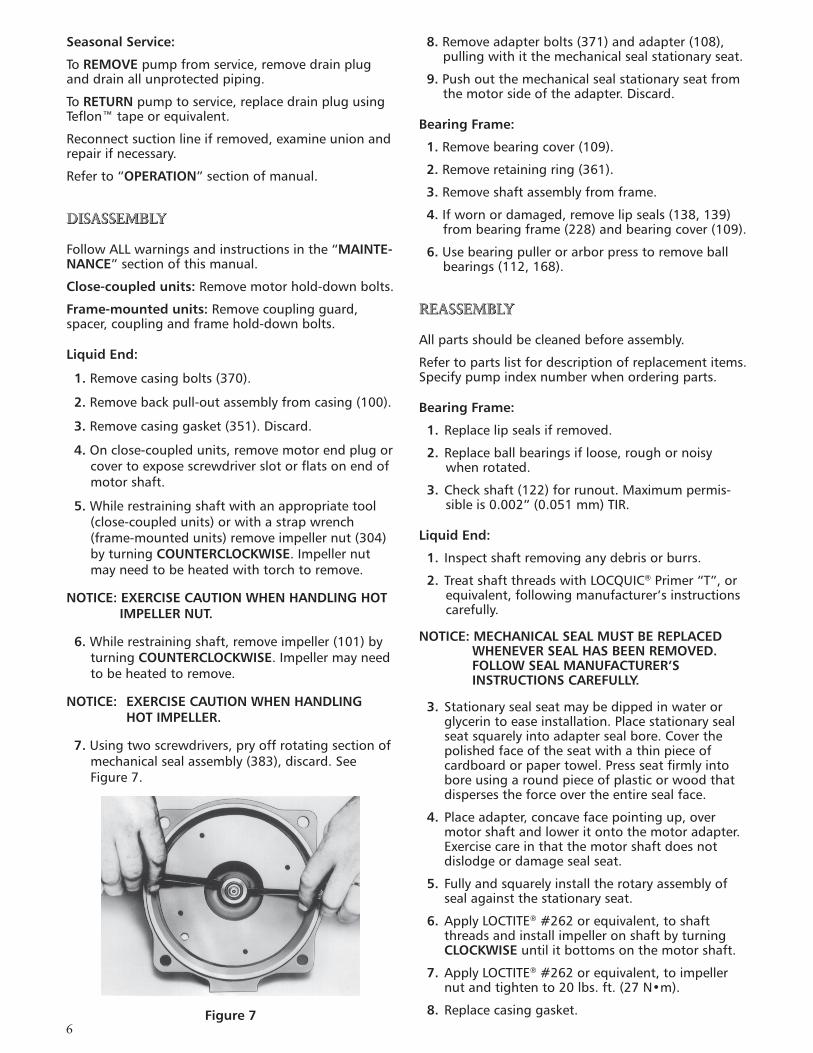
7.Usingtwoscrewdrivers,pryoffrotatingsectionofmechanicalsealassembly(383),discard.SeeFigure7.
Figure 7
8.Removeadapterbolts(371)andadapter(108),pullingwithitthemechanicalsealstationaryseat.
9.Pushoutthemechanicalsealstationaryseatfromthemotorsideoftheadapter.Discard.
Bearing Frame:
1.Removebearingcover(109).
2.Removeretainingring(361).
3.Removeshaftassemblyfromframe.
4. Ifwornordamaged,removelipseals(138,139)frombearingframe(228)andbearingcover(109).
6.Usebearingpullerorarborpresstoremoveballbearings(112,168).
REASSEMBLY
Allpartsshouldbecleanedbeforeassembly.
Refertopartslistfordescriptionofreplacementitems.Specifypumpindexnumberwhenorderingparts.
Bearing Frame:
1. Replacelipsealsifremoved.
2. Replaceballbearingsifloose,roughornoisywhenrotated.
3.Checkshaft(122)forrunout.Maximumpermis-sibleis0.002”(0.051mm)TIR.
Liquid End:
1. Inspectshaftremovinganydebrisorburrs.
2. TreatshaftthreadswithLOCQUIC®Primer“T”,orequivalent,followingmanufacturer’sinstructionscarefully.
NOTICE: MECHANICAL SEAL MUST BE REPLACED WHENEVER SEAL HAS BEEN REMOVED. FOLLOW SEAL MANUFACTURER’S INSTRUCTIONS CAREFULLY.
3. Stationarysealseatmaybedippedinwaterorglycerintoeaseinstallation.Placestationarysealseatsquarelyintoadaptersealbore.Coverthepolishedfaceoftheseatwithathinpieceofcardboardorpapertowel.Pressseatfirmlyintoboreusingaroundpieceofplasticorwoodthatdispersestheforceovertheentiresealface.
4. Placeadapter,concavefacepointingup,overmotorshaftandloweritontothemotoradapter.Exercisecareinthatthemotorshaftdoesnotdislodgeordamagesealseat.
5. Fullyandsquarelyinstalltherotaryassemblyofsealagainstthestationaryseat.
6.ApplyLOCTITE®#262orequivalent,toshaftthreadsandinstallimpelleronshaftbyturningCLOCKWISE untilitbottomsonthemotorshaft.
7.ApplyLOCTITE®#262orequivalent,toimpellernutandtightento20lbs.ft.(27N•m).
8. Replacecasinggasket.
7
9. Replacecasingbolts,tighteningto37lbs.ft.(50N•m)inacrossingsequence.
10.Checkreassembledunitforbindingbyrotatingshaft.
11. Ifrubbingexists,loosencasingboltsandproceedwithtighteningsequenceagain.
12.Onclose-coupledunits,replacemotorendplugorcoverandmotorhold-downbolts.
13.Onframe-mountedunits,replacecoupling,spac-er,couplingguardandframehold-downbolts.
NOTICE: ALWAYS RECHECK BOTH COUPLING ALIGNMENTS AFTER MAKING ANY ADJUSTMENTS.
14. Referto“COUPLING ALIGNMENT”sectionofmanualtorealignshaft.
15.Assemblyiscomplete.
100 101 383 408 108
371370381304358
Mechanical Seal Options Equipment Service Rotary Stationary Elastomers Metal Parts
Standard General Ceramic BUNA-N
Heavy-Duty Carbon Ni-Resist BUNA-N 300Series
Optional Hi-Temperature Ni-Resist EPR StainlessSteel
Chemical Ceramic Viton
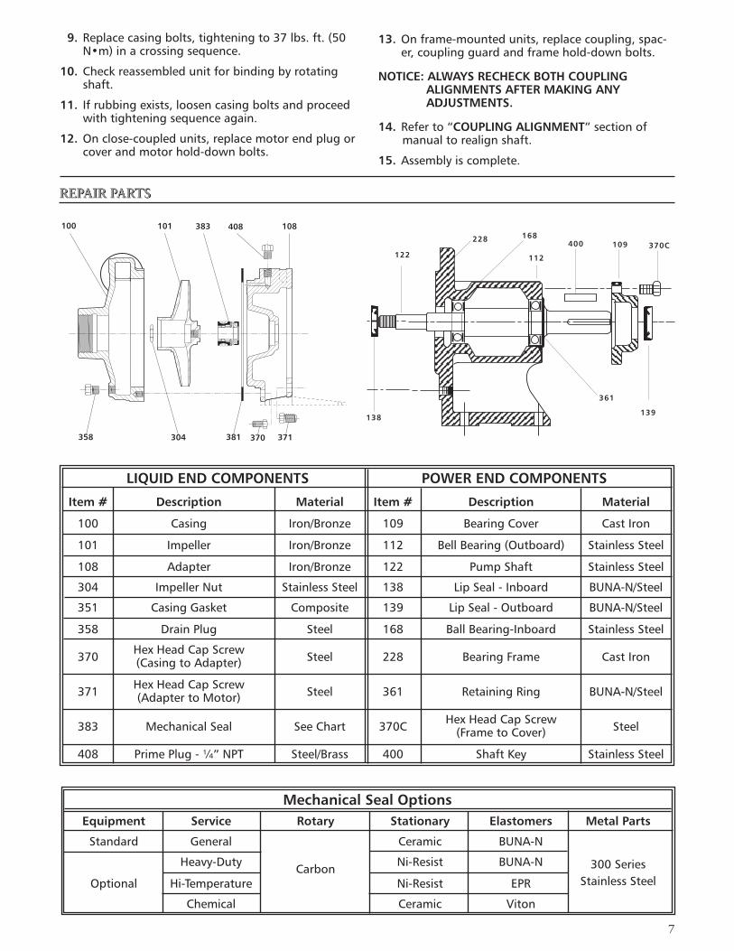
LIQUID END COMPONENTS POWER END COMPONENTS
Item # Description Material Item # Description Material
100 Casing Iron/Bronze 109 BearingCover CastIron
101 Impeller Iron/Bronze 112 BellBearing(Outboard) StainlessSteel
108 Adapter Iron/Bronze 122 PumpShaft StainlessSteel
304 ImpellerNut StainlessSteel 138 LipSeal-Inboard BUNA-N/Steel
351 CasingGasket Composite 139 LipSeal-Outboard BUNA-N/Steel
358 DrainPlug Steel 168 BallBearing-Inboard StainlessSteel
370 HexHeadCapScrew Steel 228 BearingFrame CastIron (CasingtoAdapter)
371 HexHeadCapScrew Steel 361 RetainingRing BUNA-N/Steel (AdaptertoMotor)
383 MechanicalSeal SeeChart 370C HexHeadCapScrew Steel (FrametoCover)
408 PrimePlug-¼”NPT Steel/Brass 400 ShaftKey StainlessSteel
361
138
122
228 168
112
400 109 370C
139
REPAIR PARTS
8
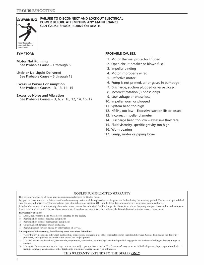
TROUBLESHOOTING
FAILURE TO DISCONNECT AND LOCKOUT ELECTRICAL POWER BEFORE ATTEMPTING ANY MAINTENANCE CAN CAUSE SHOCK, BURNS OR DEATH.
SYMPTOM:
Motor Not Running SeeProbableCause–1through5
Little or No Liquid Delivered SeeProbableCause–6through13
Excessive Power Consumption SeeProbableCauses–3,13,14,15
Excessive Noise and Vibration SeeProbableCauses–3,6,7,10,12,14,16,17
PROBABLE CAUSES:
1.Motorthermalprotectortripped2.Opencircuitbreakerorblownfuse3.Impellerbinding4.Motorimproperlywired5.Defectivemotor6.Pumpisnotprimed,airorgasesinpumpage7.Discharge,suctionpluggedorvalveclosed8.Incorrectrotation(3phaseonly)9.Lowvoltageorphaseloss10.Impellerwornorplugged11.Systemheadtoohigh12.NPSHAtoolow–Excessivesuctionliftorlosses13.Incorrectimpellerdiameter14.Dischargeheadtoolow–excessiveflowrate15.Fluidviscosity,specificgravitytoohigh16.Wornbearing17.Pump,motororpipingloose
WARNING
Hazardousvoltagecanshock,burnorcausedeath.
GOULDS PUMPS LIMITED WARRANTYThis warranty applies to all water systems pumps manufactured by Goulds Pumps.Any part or parts found to be defective within the warranty period shall be replaced at no charge to the dealer during the warranty period. The warranty period shall exist for a period of twelve (1�) months from date of installation or eighteen (18) months from date of manufacture, whichever period is shorter.A dealer who believes that a warranty claim exists must contact the authorized Goulds Pumps distributor from whom the pump was purchased and furnish complete details regarding the claim. The distributor is authorized to adjust any warranty claims utilizing the Goulds Pumps Customer Service Department.
The warranty excludes:(a) Labor, transportation and related costs incurred by the dealer;(b) Reinstallation costs of repaired equipment;(c) Reinstallation costs of replacement equipment;(d) Consequential damages of any kind; and,(e) Reimbursement for loss caused by interruption of service.
For purposes of this warranty, the following terms have these definitions:(1) “Distributor” means any individual, partnership, corporation, association, or other legal relationship that stands between Goulds Pumps and the dealer in purchases, consignments or contracts for sale of the subject pumps.(�) “Dealer” means any individual, partnership, corporation, association, or other legal relationship which engages in the business of selling or leasing pumps to customers.(3) “Customer” means any entity who buys or leases the subject pumps from a dealer. The “customer” may mean an individual, partnership, corporation, limited liability company, association or other legal entity which may engage in any type of business.
THIS WARRANTY EXTENDS TO THE DEALER ONLY.
9
ITT
Goulds Pumps, G&L and the ITT Engineered Blocks Symbol are registered trademarks and tradenames of ITT Corporation.
Loctite and Locquic are registered trademarks of Loctite Corporation.
SPECIFICATIONSARESUBJECTTOCHANGEWITHOUTNOTICE.
IM007R04 September, 2006© 2006 ITT Corporation
Engineered for life
Commercial Water
10
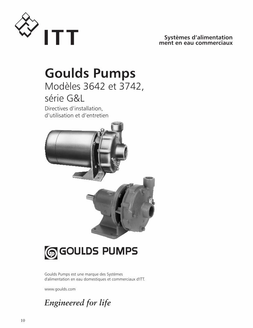
ITTGoulds PumpsModèles 3642 et 3742, série G&LDirectives d’installation, d’utilisation et d’entretien
Goulds Pumps est une marque des Systèmes d'alimentation en eau domestiques et commerciaux d'ITT.
www.goulds.com
Engineered for life
Systèmes d’alimentation ment en eau commerciaux
11
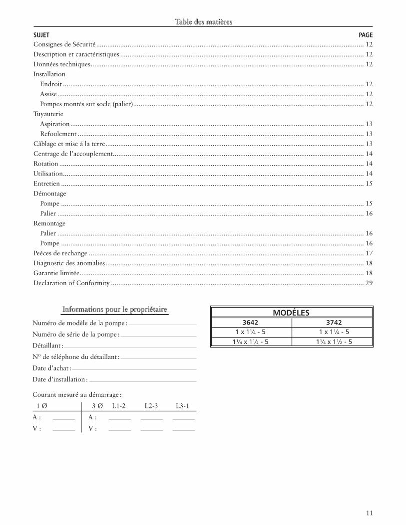
MODÉLES 3642 3742 1x1¼-5 1x1¼-5 1¼x1½-5 1¼x1½-5
SUJET PAGEConsignes de Sécurité ................................................................................................................................................. 1�Description et caractéristiques .................................................................................................................................... 1�Données techniques .................................................................................................................................................... 1�Installation Endroit ................................................................................................................................................................... 1� Assise ...................................................................................................................................................................... 1� Pompes montés sur socle (palier) ............................................................................................................................. 1�Tuyauterie Aspiration ............................................................................................................................................................... 13 Refoulement ........................................................................................................................................................... 13Câblage et mise á la terre ............................................................................................................................................ 13Centrage de l’accouplement ........................................................................................................................................ 14Rotation ..................................................................................................................................................................... 14Utilisation ................................................................................................................................................................... 14Entretien .................................................................................................................................................................... 15Démontage Pompe .................................................................................................................................................................... 15 Palier ...................................................................................................................................................................... 16Remontage Palier ...................................................................................................................................................................... 16 Pompe .................................................................................................................................................................... 16Peéces de rechange ..................................................................................................................................................... 17Diagnostic des anomalies ............................................................................................................................................ 18Garantie limitée .......................................................................................................................................................... 18Declaration of Conformity ......................................................................................................................................... �9
Informations pour le propriétaire
Numéro de modèle de la pompe :
Numéro de série de la pompe :
Détaillant :
Nº de téléphone du détaillant :
Date d’achat :
Date d’installation :
Courant mesuré au démarrage :
1 Ø 3 Ø L1-� L�-3 L3-1
A : A :
V : V :
1�
DONNÉES TECHNIQUES
Températuremaximaleduliquide: 100ºC(212ºF)–avecjointstandard 120ºC(250ºF)–avecjointpourhautes températuresenoption.
Pressiondeservicemaximale:862kPa(125lb/po2)
Démarragesparheure:20,répartisuniformément
INSTALLATION
Endroit:
Placerlapompeaussiprésdelasourcedeliquidequepossible:au-dessousduniveauduliquidepourleréamorçage.
Laissersuffisammentd’espacepourl’entretienetl’aération.Protégerl’appareilcontrelesintempéries,lesinondationsetlegel.
Pompes montés sur moteur:
Lespompespeuventêtreinstalléssurunesurfacehori-zontale,inclinéouverticale,maislemoteurnedoitpasêtreplusbasquelapompe.
AVIS: NE PAS PLACER LE MOTEUR PLUS BAS QUE LA POMPE AFIN DE LE PROTÉGER CONTRE LES FUITES ET L’EAU DE CONDENSATION.
Assise:
UneassiseplaneetsolideDOIT êtreprévuepourempêcherqueleserragedesboulonsd’ancragenecausededéformationnidecontrainte.Lemontagesurcaoutchoucestpermispourréduirelebruitetlesvibrations.
Serrerlesboulonsdefixationdelapompeavantdelaraccorderálatuyauterie.
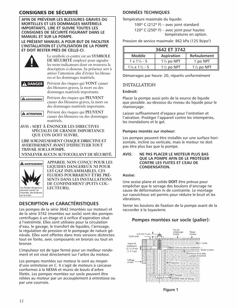
Pompes montées sur socle (palier):
Figure 1
CONSIGNES DE SÉCURITÉAFIN DE PRÉVENIR LES BLESSURES GRAVES OU MORTELLES ET LES DOMMAGES MATÉRIELS IMPORTANTS, LIRE ET SUIVRE TOUTES LES CONSIGNES DE SÉCURITÉ FIGURANT DANS LE MANUEL ET SUR LA POMPE.LE PRÉSENT MANUEL A POUR BUT DE FACILITER L’INSTALLATION ET L’UTILISATION DE LA POMPE ET DOIT RESTER PRÈS DE CELLE-CI.
Le symbole ci-contre est un SYMBOLE DE SÉCURITÉ employé pour signaler les mots-indicateurs dont on trouvera la description ci-dessous. Sa présence sert à attirer l’attention afin d’éviter les blessu-res et les dommages matériels.Prévient des risques qui VONT causer des blessures graves, la mort ou des dommages matériels importants.Prévient des risques qui PEUVENT causer des blessures graves, la mort ou des dommages matériels importants.Prévient des risques qui PEUVENT causer des blessures ou des dommages matériels.
AVIS : SERT À ÉNONCER LES DIRECTIVES SPÉCIALES DE GRANDE IMPORTANCE QUE L’ON DOIT SUIVRE.
LIRE SOIGNEUSEMENT CHAQUE DIRECTIVE ET AVERTISSEMENT AVANT D’EFFECTUER TOUT TRAVAIL SUR LA POMPE.N’ENLEVER AUCUN AUTOCOLLANT DE SÉCURITÉ.
APPAREIL NON CONÇU POUR LES LIQUIDES DANGEREUX NI POUR LES GAZ INFLAMMABLES. CES FLUIDES POURRAIENT ÊTRE PRÉ-SENTS DANS LES INSTALLATIONS DE CONFINEMENT (PUITS COL-LECTEURS).
DESCRIPTION et CARACTÉRISTIQUESLespompesdelasérie3642(montéessurmoteur)etdelasérie3742(montéessursocle)sontdespompescentrifugesáunétageetáorificed’aspirationsituéál’extrémité.Ellessontutiliséespourlacirculationd’eau,legavage,letransfertdeliquides,l’arrosage,larégulationdepressionetlepompagedenaturegé-nérale.Ellessontoffertesdanstroisversionsdistinctes:toutenfonte,aveccomposantsenbronzeoutoutenbronze.
L’impulseurestdetypefermépourunmeilleurrende-mentetestvissédirectementsurl’arbredumoteur.
Lespompesmontéessurmoteurlesontaumoyend’uneentretoiseenC.IIs’agitdemoteursácarcasseconformesálaNEMAetmunisdeboutsd’arbrefiletés.Lespompesmontéessursoclepeuventêtrereliéesaumoteurparunaccouplementáentretoiseouparunecourroie.
DANGER
AVERTISSEMENT
ATTENTION
AVERTISSEMENT
Lesfluidesdangereuxpeuventcauserunincendie,desbrûluresoulamort.
3642 ET 3742 Modéle Aspiration Refoulement 1x1¼-5 1¼poNPT 1poNPT 1¼x1½-5 1½poNPT 1¼poNPT
Manchon
Rondelle
Patte de blocage
Dessus de la dalle,propre et humecté
Coulis
Coins ou cales de nivellement —laissés en place
Plaqued’assise
Trou deremplissage(Coulis)6,35 mm (1⁄4 po)
Coulis arasé
Espace denivellement:
12,7 á 19 mm(1⁄2 á 3⁄4 po)
Coffrageen bois
13
Notes Silapompeestplacéeplushautquelasourcedeliq-uide,onDOIT suivrelesdirectivessuivantes:
-Afindeprévenirlespochesd’air,aucunélémentdelatuyauteried’aspirationnedevraitêtreplushautquel’orificed’aspirationdelapompe.
-Latuyauteriedevraitêtresanscesseinclinéeverslehautápartirdelasourcedeliquide.
-Utiliserunclapetdepiedouunclapetdenon-retourSEULEMENT sicelaestnécessairepouramorcerlapompeoulamainteniramorcéeaucoursdesinterruptionsdeservice.
-Lasectiondepassagedelacrépineoudel’évasementdutuyaud’aspirationDOITêtreaumoinsletripledecelledutuyau.
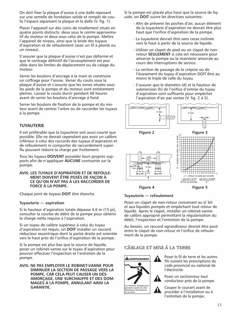
-S’assurerquelediamétre(d)etlahauteurdesubmersion(h)del’orificed’entréedutuyaud’aspirationsontsuffisantspourempêcherl’aspirationd’airparvortex(V.fig.2á5).
Tuyauterie — refoulement
Poserunclapetdenon-retourconvenantaud´bitetauxliquidespompésetempêchanttoutretourdeliquide.Aprésleclapet,installerunrobinet-vannedecalibreappropriépermettantlarégularisationdudébit,l’inspectionetl’entretiendelapompe.
Aubesoin,unraccordagrandisseurdevraitêtreposéentreleclapetdenon-retouretl’orificederefoule-mentdelapompe.
CÂBLAGE ET MISE Á LA TERRE
Poserlefildeterreetlesautresfilssuivantlesprescriptionsducodeprovincialounationaldel’électricité.
Poserunsectionneurtoutconducteurprésdelapompe.
Couperlecourantavantdeprocéderál’installationouál’entretiendelapompe.
Ondoitfixerlaplaqued’assiseáunedallereposantsurunesemelledefondationsolideetremplirdecou-lisl’espacesépareantlaplaqueetladalle(V.fig.1).
Placerl’appareilsurdescoinsdenivellementsituésenquatrepointsdistincts:deuxsouslecentreapproxima-tifdumoteuretdeuxsousceluidelapompe.Mettrel’appareildeniveau,ainsiquelabridedestuyauxd’aspirationetderefoulement(avecunfiláplombouunniveau).
S’assurerquelaplaqued’assisen’estpasdéforméetquelecentragedéfinitifdel’accouplementestpos-sibledansleslimitesdedéplacementoudecalagedumoteur.
Serrerlesboulonsd’ancrageálamainetconstruireuncoffragepourl’assise.Verserducoulissouslaplaqued’assiseets’assurerqueleszonessituéessouslespiedsdelapompeetdumoteursontentiérementpleines.Laisserlecoulisdurcirpendant48heuresavantdeserrerlesboulonsd’ancrageáfond.
Serrerlesboulonsdefixationdelapompeetdumo-teuravantdecentrerl’arbreouderaccorderlestuyauxálapompe.
TUYAUTERIE
IIestpréférablequelatuyauteriesoitaussicourtequepossible.Ellenedevraitcependantpasavoiruncalibreinférieuráceluidesraccordsdestuyauxd’aspirationetderefoulementnicomporterderaccordementsuper-flupouvantréduirelachargeparfrottement.
TouslestuyauxDOIVENT posséderleurspropressup-portsafinden’appliquerAUCUNE contraintesurlapompe.
AVIS: LES TUYAUX D’ASPIRATION ET DE REFOULE-MENT DOIVENT ÊTRE POSÉS DE FAÇON Á CE QU’ON N’AIT PAS Á LES RACCORDER DE FORCE Á LA POMPE.
ChaquejointdetuyauxDOIT êtreétanche.
Tuyauterie — aspiration
Silahauteurd’aspirationtotaledépasse4,6m(15pi),consulterlacourbededébitdelapompepourobtenirlachargenetterequiseál’aspiration.
Siuntuyaudecalibresupérieuráceluidutuyaud’aspirationestrequis,onDOIT installerunraccordréducteurexcentriquedontlapartiedroiteestorientéeverslehautprésdel’orificed’aspirationdelapompe.
Silapompeestplusbasquelasourcedeliquide,poserunrobinet-vannesurletuyaud’aspirationpourpouvoireffectuerl’inspectionetl’entretiendelapompe.
AVIS: NE PAS EMPLOYER LE ROBINET-VANNE POUR DIMINUER LA SECTION DE PASSAGE VERS LA POMPE, CAR CELA PEUT CAUSER UN DÉS-AMORÇAGE, UNE SURCHAUFFE ET DES DOM-MAGES Á LA POMPE, ANNULANT AINSI LA GARANTIE.
h min.
d d
h min.
d d
1,5dmin.
3,0dmin.
h min.
d min.2
16151413121110
987654321
h =
hau
teur
de
subm
. min
. en
pied
s H
1 2 3 4 5 6 7 8 9 10111213141516 vv = vitesse en pieds par seconde
= gal.min x 0,321section de passage
gal./min x 0,4085d 2
Figure 2 Figure 3
Figure 4 Figure 5
AVERTISSEMENT
Lestensionsdangereusespeuventcauserunchocélectrique,desbrûluresoulamort.
14
L’alimentationélectriqueDOIT êtreconformeauxspécificationsdelaplaquesignalétique.Uneten-sioninappropriéepeutcauserunincendieoudesdommagesaumoteuretannulelagarantie.
LesmoteursmonophaséssansprotectionintégréeDOIVENT êtremunisdecontacteursetdedisposi-tifsdeprotectioncontrelessurchargesther-miques,etlesmoteurstriphasés,dedémarreursádispositifdeprotectioncontrelasurcharge.Consulterlaplaquesignalétiquedumoteur.
N’utiliserquedufildecuivrepourlamiseálaterreetl’alimentationdumoteur.LecalibredufildeterreDOIT êtreaumoinségaláceluidesfilsd’alimentation,etlesfilsdevraienttousêtrechromocodéspourfaciliterl’entretien.
Suivresoigneusementleschémadecâblagesurlaplaquesignalétiqueoulecache-bornesdumoteur.
OMETTRE LA MISE Á LA TERRE PERMANENTE DE LA POMPE, DU MOTEUR OU DES COMMANDES AVANT LE BRANCHEMENT Á LA SOURCE DE COURANT PEUT SE TRADUIRE PAR UNE COMMOTION ÉLECTRIQUE, DES BRÛLURES OU LA MORT.
CENTRAGE DE L’ACCOUPLEMENT
OMETTRE LA MISE HORS SERVICE ET LE VERROUILLAGE EN POSITION OUVERTE DE LA SOURCE DE COURANT AVANT D’EFFECTUER L’ENTRETIEN PEUT ENTRAÎNER DES BLESSURES GRAVES.
OnDOIT vérifierlecentrageavantlamiseenservice(V.fig.6).
Serrertouslesboulonsdefixationavantdevérifierlecentrage.
Siunrecentrageestnécessaire,onnedoitdéplacerquelemoteur.Suivrelesdirectivespourlecalage.
Figure 6
Désalignementparalléle(arbresparallélesmaisnonconcentriques)—Fixersurunmoyeuuncomparateurácadranquel’ontournede360ºlelongdelacircon-férencedel’autremoyeutoutennotantl’amplitudededéplacementdel’aiguille.L’alignementestcorrectsilefaux-rondtotalestde0,127mm(0,005po)oumoins.
Désalignementangulaire(arbresconcentriquesmaisnonParalléles)—Fixersurunmoyeuuncomparateurácadranquel’ontournede360ºlelongd’unefaceplanedel’autremoyeutoutennotantl’amplitudededéplacementdel’aiguille.L’alignementestcorrectsilefaux-rondtotalestde0,127mm(0,005po)oumoins.
Lecentrageconvientlorsqu’ilsatisfaitauxexigencesrelativesál’alignementparalléleetangulaire,aprésleserrageáfonddesboulonsdefixationdumoteur.
AVIS: ON DOIT TOUJOURS VÉRIFIER LES DEUX TYPES D’ALIGNEMENT APRÉS CHAQUE RÉGLAGE MÉCANIQUE.
ROTATION
AVIS: LA ROTATION DANS LE MAUVAIS SENS PEUT ENDOMMAGER LA POMPE ET ANNULE LA GARANTIE.
Larotationappropriées’effectueensensHORAIRE (versladroite),vuedel’extrémitédumoteur.Onpeutvérifierlesensderotationdel’arbredesmo-teurstriphasésparlecouvercleoul’obturateursituéál’extrémitédumoteur.
Pourinverserlarotation,intervertirdeuxdestroiscon-ducteursdumoteur.
UTILISATION
N’UTILISER AUCUNE POMPE MONTÉE SUR SOCLE DÉPOURVUE DE GRILLAGE OU D’ÉCRAN PROTECTEUR, CAR CELA PEUT ENTRAÎNER DES BLESSURES GRAVES.
L’ÉCLABOUSSEMENT OU L’IMMERSION DES MOTEURS ABRITÉS (Á OUVERTURES DE VENTILATION PROTÉGÉES) PEUT CAUSER UN INCENDIE, UNE COMMOTION ÉLECTRIQUE, DES BRÛLURES OU LA MORT.
LE FONCTIONNEMENT Á DÉBIT NUL OU PRESQUE PEUT PRODUIRE DES TEMPÉRATURES ÉLEVÉES, DES BLESSURES OU DES DOMMAGES MATÉRIELS.
AVERTISSEMENT
Tensiondangereuse
Lamachineriedange-reusepeutcauserdesblessuresoulamort.
AVERTISSEMENT
Parallel
Angular
Paralléle
Angulaire
AVERTISSEMENT
Lestensionsdangereusespeuventcauserunchocélectrique,desbrûluresoulamort.
AVERTISSEMENT
Leshautestempératurespeuventcauserdesblessuresetdesdommagesmatériels.
Lamachineriedange-reusepeutcauserdesblessuresoulamort.
AVERTISSEMENT
15
AVIS: NE PAS UTILISER UNE POMPE DÉSAORCÉES AFIN DE NE PAS EN ENDOMMAGER LE JOINT.
Apréslastabilisationdusystémedansdesconditionsdeservicenormales,vérifierlatuyauterie.Aubesoin,réglerlapositiondessupportsdetuyauterie.
Ladifférencedetempératureentrelemoteuretlapompemontéesursoclepeutaltérerlecentragedel’accouplement.VérifierlecentragedenouveauensuivantlesdirectivesetlesavertissementsfigurantálasectionCENTRAGE DE L’ACCOUPLEMENTci-dessus.
ENTRETIEN
OMETTRE DE COUPER LE COURANT AVANT D’EFFECTUER L’ENTRETIEN PEUT SE TRADUIRE PAR UNE COMMOTION ÉLECTRIQUE, DES BRÛLURES OU LA MORT.
OMETTRE DE RÉDUIRE LA PRESSION DU SYSTÉME ET DE LE VIDANGER AVANT D’EFFECTUER L’ENTRETIEN PEUT CAUSER DES DOMMAGES MATÉRIELS, DES BLESSURES OU LA MORT.
Pompes montés sur moteur:
Lesroulementssontsituésál’intérieurdumoteur.Pourlalubrification,consulterlesdirectivesdufabri-cantdumoteur.
Pompes montées sur socle (palier):
Lesroulementsdupalierdelapompesontgraissésávie.Leurlubrificationestdoncimpossibleetinutile.
Suivrelesdirectivesdelubrificationdufabricantdumoteuretdel’accouplement.
Usage saisonnier:
PourmettreunepompeHORS service,déposertouslesbouchonsdevidangeetvidertouslestuyaux.
PourremettreunepompeEN service,reposertouslesbouchonsdevidangeaprésenavoirrecouvertlesfiletsderubandeTéflonMCoul’équivalent.
Raccorderletuyaud’aspirationálapompes’ilaétédésaccouplé,examinerleraccordunioneteffectuerlesréparationsn´cessaires.
RéamorceretfairefonctionnerlapompesuivantlesdirectivesetlesavertissementsfigurantálasectionUTILISATION.
DÉMONTAGE
SuivreCHAQUE directiveetavertissementfigurantálasectionENTRETIEN decemanuel.
Danslecasdespompesmontéessurmoteur,enleverlesboulonsdefixationdecedernier.
Quantauxpompesmontéessursocle,enleverlegril-lageoul’écranprotecteur,l’entretoise,l’accouplementetlesboulonsdefixationdusocle.
Pompe:
1.Enleverlesvisdefixationducorpsdepompe(370).
2.Écarterl’ensemblepompeducorpsdepompe(100).
3.Enleverlejointducorpsdepompe(351),puislejeter.
4.Danslecasdespompesmontéessurmoteur,enleverl’obturateuroulecouvercled’extrémitédumoteurpouraccéderálafenteouauxméplatsdeblocagesituésál’extrémitédel’arbre.
5.Bloquerl’arbredelapompemontéesurmo-teuravecl’outilapproprié(ouceluidelapompemontéesursocleavecunserre-tubesásangle),dévisserl’écrou(304)del’impulseurdansleSENS ANTIHORAIRE:ilpeutêtrenécessairedefairechaufferd’abordl’écrouauchalumeau.
AVIS: FAIRE ATTENTION EN MANIPULANT L’ÉCROU CHAUD DE L’IMPULSEUR.
6.Maintenirl’arbrebloquéetdévisser(SENS ANTI-HORAIRE)etenleverl’impulseur(101):ilpeutêtrenécessairedelefaired’abordchauffer.
AVIS: FAIRE ATTENTION EN MANIPULANT L’IMPULSEUR CHAUD.
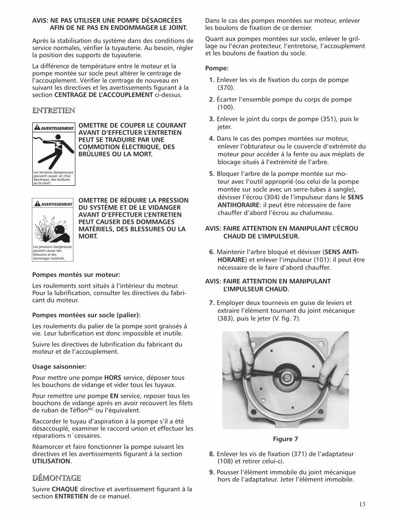
7.Employerdeuxtournevisenguisedeleviersetextrairel’élémenttournantdujointmécanique(383),puislejeter(V.fig.7).
Figure 7
8.Enleverlesvisdefixation(371)del’adaptateur(108)etretirercelui-ci.
9.Pousserl’élémentimmobiledujointmécaniquehorsdel’adaptateur.Jeterl’élémentimmobile.
AVERTISSEMENT
Lestensionsdangereusespeuventcauserunchocélectrique,desbrûluresoulamort.
Lespressionsdangereusespeuventcauserdesblessuresetdesdommagesmatériels.
AVERTISSEMENT
16
Palier:
1.Enleverlecouvercle(109)depalier.
2.Enleverlabaguederetenue(361).
3.Sortirl’arbredupalier.
4.Silesjointsálévre(138et139)sontusésouendommagés,lesextrairedupalier(228)etducouvercle(109)depalier.
5.Ál’aided’unarrache-roulementoud’unepresseámandriner,extrairelesroulements(112et168).
REMONTAGE
Nettoyeretinspecterchaquepiécedelapompelorsquel’oncommandedespiéces.
Voirlalistedespiécespourobtenirladescriptiondespiécesderechange.Préciserlenumérodepiécedelapompelorsquel’oncommandedespiéces.
Palier:
1.Remplacerlesjointsálévres’ilsontétéenlevés.
2.Remplacerlesroulementsábilless’ilsontdujeu,s’ilsnetournentpasrondous’ilssontbruyants.
3.Vérifiersil’arbre(122)comportedesfaux-ronds:lefaux-rondmaximaladmissibleestde0,051mm(0,002po).
Pompe:
1.Inspecterl’arbreetenleverlesaspéritésetlesrésidus.
2.Appliquerdel’apprêtPrimer“T”deLOCQUICMDoul’équivalentsurlesfiletsdel’arbre:suivrelesdirec-tivesdufabricantavecsoin.
AVIS: LE JOINT ÉCANIQUE DOIT ÊTRE REMPLACÉ CHAQUE FOIS QU’ON L’ENLÉVE. SUIVRE LES DIRECTIVES DU FABRICANT AVEC SOIN.
3.Onpeutmouillerouglycérinerlejointimmobilepourenfaciliterlapose.Placerlejointcorrecte-mentcontresonsiége(surl’adaptateur).Recou-vrirlafacepoliedujointd’unmorceaudecartonminceoud’essuie-tout.Pousserlejointáfonddanssonsiégeavecunobjetrondenplastiqueouenboispourrépartirlapressionsurtoutlejoint.
4.Insérerl’arbreparlecôtéconvexedel’adaptateur(V.illustrationsuivante).Prendregardequel’arbrenedélogenin’endommagelejoint.
5.Pousserl’ensemblejointtournantáfondetáangledroitcontrelejointimmobile.
6.AppliquerduLOCTITEMDno262oul’équivalentsurlesfiletsdel’arbreetvisserl’impulseurábloc(SENS HORAIRE)surl’arbre.
7.MettreduLOCTITEMDno262oul’équivalentsurlesfiletsdel’écroudel’impulseuretserrerl’écrouá27N•m(20lbf•pi).
8.Remettrelejointducorpsdepompe.
9.Reposeretserrerlesvisdefixationducorpsdepompeá50N•m(37lbf•pi)etencroix.
10.Unefoislapomperemontée,fairetournerl’arbrepourvérifiers’ilyagrippage.
11.Encasdefrottement,desserrerlesvisducorpsdepompeetprocéderáunnouveauresserrage.
12.S’ils’agitd’unepompemontéesurmoteur,reposerl’obturateuroulecouvercled’extrémitédumoteurainsiquelesboulonsdefixationdecedernier.
13.S’ils’agitd’unepompemontéesursocle,reposerl’accouplement,l’entretoise,legrillageoul’écranprotecteurainsiquelesboulonsdefixationdusocle.
AVIS: ON DOIT TOUJOURS VÉRIFIER LES DEUX TYPES D’ALIGNEMENT APRÉS CHAQUE RÉGLAGE MÉCANIQUE.
14.Pourrecentrerl’arbre,voirlasectionCENTRAGE DE L’ACCOUPLEMENTci-dessus.
15.Leremontageestmaintenantterminé.
17
100 101 383 408 108
371370381304358
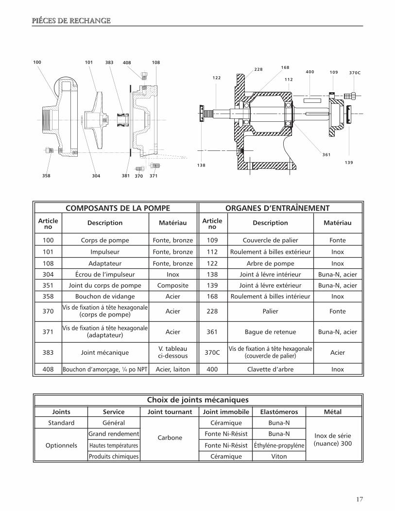
Choix de joints mécaniques Joints Service Joint tournant Joint immobile Elastómeros Métal
Standard Général Céramique Buna-N
Grandrendement Carbone FonteNi-Résist Buna-N Inoxdesérie Optionnels Hautestempératures FonteNi-Résist Éthyléne-propyléne (nuance)300
Produitschimiques Céramique Viton
PIÉCES DE RECHANGE
COMPOSANTS DE LA POMPE ORGANES D’ENTRAÎNEMENT
Article Article no Description Matériau no Description Matériau
100 Corpsdepompe Fonte,bronze 109 Couvercledepalier Fonte
101 Impulseur Fonte,bronze 112 Roulementábillesextérieur Inox
108 Adaptateur Fonte,bronze 122 Arbredepompe Inox
304 Écroudel’impulseur Inox 138 Jointálévreintérieur Buna-N,acier
351 Jointducorpsdepompe Composite 139 Jointálévreextérieur Buna-N,acier
358 Bouchondevidange Acier 168 Roulementábillesintérieur Inox
370 Visdefixationátêtehexagonale Acier 228 Palier Fonte (corpsdepompe)
371 Visdefixationátêtehexagonale Acier 361 Baguederetenue Buna-N,acier (adaptateur)
383 Jointmécanique V.tableau 370C Visdefixationátêtehexagonale Acier ci-dessous (couvercledepalier)
408 Bouchond’amorçage,¼poNPT Acier,laiton 400 Clavetted’arbre Inox
361
138
122
228 168
112
400 109 370C
139
18
DIAGNOSTIC DES ANOMALIES
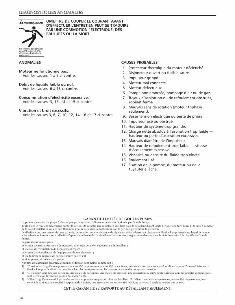
OMETTRE DE COUPER LE COURANT AVANT D’EFFECTUER L’ENTRETIEN PEUT SE TRADUIRE PAR UNE COMMOTION ´ELECTRIQUE, DES BRÛLURES OU LA MORT.
ANOMALIES
Moteur ne fonctionne pas: Voirlescauses1á5ci-contre.
Débit de liquide faible ou nul: Voirlescauses6á13ci-contre.
Consommation d’électricité excessive: Voirlescauses3,13,14et15ci-contre.
Vibration et bruit excessifs: Voirlescauses3,6,7,10,12,14,16et17ci-contre.
CAUSES PROBABLES1. Protecteurthermiquedumoteurdéclenché.2. Disjoncteurouvertoufusiblesauté.3. Impulseurgrippé.4. Moteurmalconnecté.5. Moteurdéfectueux.6. Pompenonamorcée,pompaged’airoudegaz.7. Tuyauxd’aspirationouderefoulementobstrués,
robinetfermé.8. Mauvaissensderotation(moteurtriphasé
seulement).9. Bassetensionélectriqueoupertedephase.10. Impulseuruséouobstrué.11. Hauteurdusystémetropgrande.12. Chargenetteabsolueál’aspirationtropfaible—
hauteurouperted’aspirationexcessives.13. Mauvaisdiamétredel’impulseur.14. Hauteurderefoulementtropfaible—vitesse
d’écoulementexcessive.15. Viscositéoudensitédufluidetropélevée.16. Roulementusé.17. Fixationdelapompe,dumoteuroudela
tuyauterielâche.
AVERTISSEMENT
Lestensionsdangereusespeuventcauserunchocélectrique,desbrûluresoulamort.
GARANTIE LIMITÉE DE GOULDS PUMPSLa présente garantie s’applique à chaque pompe de système d’alimentation en eau fabriquée par Goulds Pumps.Toute pièce se révélant défectueuse durant la période de garantie sera remplacée sans frais pour le détaillant durant ladite période, qui dure douze (1�) mois à compter de la date d’installation ou dix-huit (18) mois à partir de la date de fabrication, soit la période qui expirera la première.Le détaillant qui, aux termes de cette garantie, désire effectuer une demande de règlement doit s’adresser au distributeur Goulds Pumps agréé chez lequel la pompe a été achetée et fournir tous les détails à l’appui de sa demande. Le distributeur est autorisé à régler toute demande par le biais du service à la clientèle de Goulds Pumps.La garantie ne couvre pas :a) les frais de main-d’oeuvre ou de transport ni les frais connexes encourus par le détaillant ;b) les frais de réinstallation de l’équipement réparé ;c) les frais de réinstallation de l’équipement de remplacement ;d) les dommages indirects de quelque nature que ce soit ;e) ni les pertes découlant de la panne.Aux fins de la présente garantie, les termes ci-dessous sont définis comme suit :1) «Distributeur» signifie une personne, une société de personnes, une société de capitaux, une association ou autre entité juridique servant d’intermédiaire entre Goulds Pumps et le détaillant pour les achats, les consignations ou les contrats de vente des pompes en question.�) «Détaillant» veut dire une personne, une société de personnes, une société de capitaux, une association ou autre entité juridique dont les activités commerciales sont la vente ou la location de pompes à des clients.3) «Client» signifie une entité qui achète ou loue les pompes en question chez un détaillant. Un «client» peut être une personne, une société de personnes, une société de capitaux, une société à responsabilité limitée, une association ou autre entité juridique se livrant à quelque activité que ce soit.
CETTE GARANTIE SE RAPPORTE AU DÉTAILLANT SEULEMENT.
19
ITT
Goulds Pumps, G&L et le logo à blocs siglés ITT sont des marques déposées et de commerce d’ITT Corporation.
Loctite et Locquic sont des marques déposées de Loctite Corporation.
LESCARACTÉRISTIQUESPEUVENTCHANGERSANSPRÉAVIS.
IM007R04 Septembre, 2006© 2006, ITT Corporation
Engineered for life
Systèmes d’alimentation ment en eau commerciaux

�0
ITTGoulds PumpsSerie G&L Modelos 3642 y 3742Instrucciones de instalación, funcionamiento y mantenimiento
Goulds Pumps es una marca de fábrica de ITT Agua Residencial y Comercial.
www.goulds.com
Engineered for life
Agua Industrial
�1
MODELOS 3642 3742 1x1¼-5 1x1¼-5 1¼x1½-5 1¼x1½-5
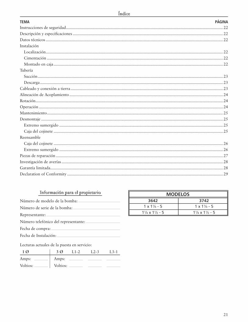
TEMA PÁGINAInstrucciones de seguridad ........................................................................................................................................... ��Descripción y especificaciones ..................................................................................................................................... ��Datos técnicos ............................................................................................................................................................. ��Instalación Localización ............................................................................................................................................................. �� Cimentación ............................................................................................................................................................ �� Montado en caja ...................................................................................................................................................... ��Tubería Succión .................................................................................................................................................................... �3 Descarga .................................................................................................................................................................. �3Cableado y conexión a tierra ....................................................................................................................................... �3Alineación de Acoplamiento ........................................................................................................................................ �4Rotación ...................................................................................................................................................................... �4Operación ................................................................................................................................................................... �4
Mantenimiento ............................................................................................................................................................ �5Desmontaje ................................................................................................................................................................. �5 Extremo sumergido ................................................................................................................................................. �5 Caja del cojinete ...................................................................................................................................................... �5Reensamble Caja del cojinete ...................................................................................................................................................... �6 Extremo sumergido ................................................................................................................................................. �6Piezas de reparación .................................................................................................................................................... �7Investigación de averías ............................................................................................................................................... �8Garantía limitada ......................................................................................................................................................... �8Declaration of Conformity .......................................................................................................................................... �9
Número de modelo de la bomba:
Número de serie de la bomba:
Representante:
Número telefónico del representante:
Fecha de compra:
Fecha de Instalación:
Lecturas actuales de la puesta en servicio:
1 Ø 3 Ø L1-� L�-3 L3-1
Amps: Amps:
Voltios: Voltios:
��
Máximapresióndetrabajo:125lib/pulg2(9barias)
Arranquesporhora:20-distribuidosuniformemente
INSTALACIÓN
Lugar:
Coloquelabombatancercadelafuentedellíquidocomoseapráctico;abajodelniveldellíquidoparadarlelacapacidadderecebado.
Dejeespacioadecuadoparapoderdarleservicioyven-tilación.Protejalaunidaddelaintemperieydañosdelaguadebidoalalluvia,inundacionesotemperaturasdecongelación.
Unidades compactas:
Lasunidadessepuedeninstalarhorizontalmente,inclinadasoverticalmenteconelmotorarribadelabomba.
AVISO: NO INSTALE CON EL MOTOR ABAJO DE LA BOMBA. CUALQUIER FUGA O CONDENSACIÓN AFECTARÁ AL MOTOR.
Cimentación:
UnacimentacióndesuperficieplanaysubstancialDEBE proporcionarseparaevitarladistorsióny/odeformacionescuandoseaprietenlospernosdelacimentación.Unmontajedegomaesaceptableparadisminuirelruidoolasvibracionesexcesivas.
Aprietelospernosdesujecióndelmotorantesdeconectarlatuberíaalabomba.
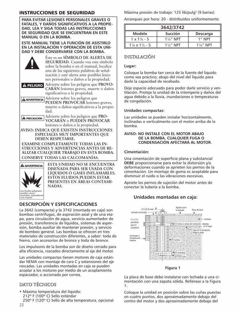
Unidades montadas en caja:
Figura 1
Laplacadebasedebeinstalarseconlechadaaunaci-mentaciónconunazapatasólida.RefiérasealaFigura1.
Coloquelaunidadenposiciónsobrelascuñaspuestasencuatropuntos,dosaproximadamentedebajodelcentrodelmotorydosaproximadamentedebajodel
INSTRUCCIONES DE SEGURIDADPARA EVITAR LESIONES PERSONALES GRAVES O FATALES, Y DAÑOS SIGNIFICATIVOS A LA PROPIE-DAD, LEA Y SIGA TODAS LAS INSTRUCCIONES DE SEGURIDAD QUE SE ENCUENTRAN EN ESTE MANUAL O EN LA BOMBA.ESTE MANUAL TIENE LA FUNCIÓN DE ASISTIRLO EN LA INSTALACIÓN Y OPERACIÓN DE ESTA UNI-DAD Y DEBE CONSERVARSE CON LA BOMBA.
Éste es un SÍMBOLO DE ALERTA DE SEGURIDAD. Cuando vea este símbolo sobre la bomba o en el manual, localice una de las siguientes palabras de señal-ización y esté alerta ante posibles lesio-nes personales o daños a la propiedad.Advierte sobre los peligros que PROVO-CARÁN lesiones graves, muerte o daños significativos a la propiedad.Advierte sobre los peligros que PUEDEN PROVOCAR lesiones graves, muerte o daños significativos a la propie-dad.Advierte sobre los peligros que PRO-VOCARÁN o PUEDEN PROVOCAR lesiones o daños a la propiedad.
AVISO: INDICA QUE EXISTEN INSTRUCCIONES ESPECIALES MUY IMPORTANTES QUE DEBEN RESPETARSE.
EXAMINE COMPLETAMENTE TODAS LAS IN-STRUCCIONES Y ADVERTENCIAS ANTES DE RE-ALIZAR CUALQUIER TRABAJO EN ESTA BOMBA.CONSERVE TODAS LAS CALCOMANÍAS.
ESTA UNIDAD NO SE ENCUENTRA DISEÑADA PARA SER USADA CON LÍQUIDOS O GASES INFLAMABLES. ESTOS FLUIDOS PUEDEN ESTAR PRESENTES EN ÁREAS CONTAMI-NADAS.
DESCRIPCIÓN Y ESPECIFICACIONESLa3642(compacta)yla3742(montadaencaja)sonbombascentrifugas,deaspiraciónaxialydeunaeta-pa,paracirculacióndeagua,servicioaumentadordepresión,transferenciadelíquidos,sistemasdeasper-sión,bombaauxiliardemantenerpresión,yserviciodebombeogeneral.Lasbombasseofrecenentresmaterialesdeconstruccióndiferentes,asaber:todadehierro,conaccesoriosdebronceytodadebronce.
Losimpulsoresdelabombasondediseñocerradoparaaltaeficiencia,roscadosdirectamentealejedelmotor.
Lasunidadescompactastienenmotoresdecajaestán-darNEMAconmontajedecaraCyextensionesdelejeroscadas.Lasunidadesmontadasencajasepuedenacoplaralosmotorespormediodeunacoplamientoespaciador,oaccionadoporcorrea.
DATO TÉCNICOS
•Máximatemperaturadelliquido:212ºF(100ºC)Selloestándar250ºF(120ºC)Sellodealtatemperatura,opcional
PELIGRO
ADVERTENCIA
PRECAUCIÓN
ADVERTENCIA
Losfluidospeligrosospuedencausarincendios,quemadurasolamuerte.
3642/3742 Modelo Succión Descarga 1x1¼-5 1¼”NPT 1”NPT 1¼x1½-5 1½”NPT 1¼”NPT
Camisa
Arandela
Uña
Tope de la fundación -limpie y moje
Lechada
Cuñas o calzas de nivelación - dejadasen el lugar
Placa de baseAgujero parala lechada(1⁄4”) (6.35 mm)
Lechada terminada
(1⁄2 a 3⁄4”)permitidapara lanivelación
Encofrado oformaleta demadera
�3
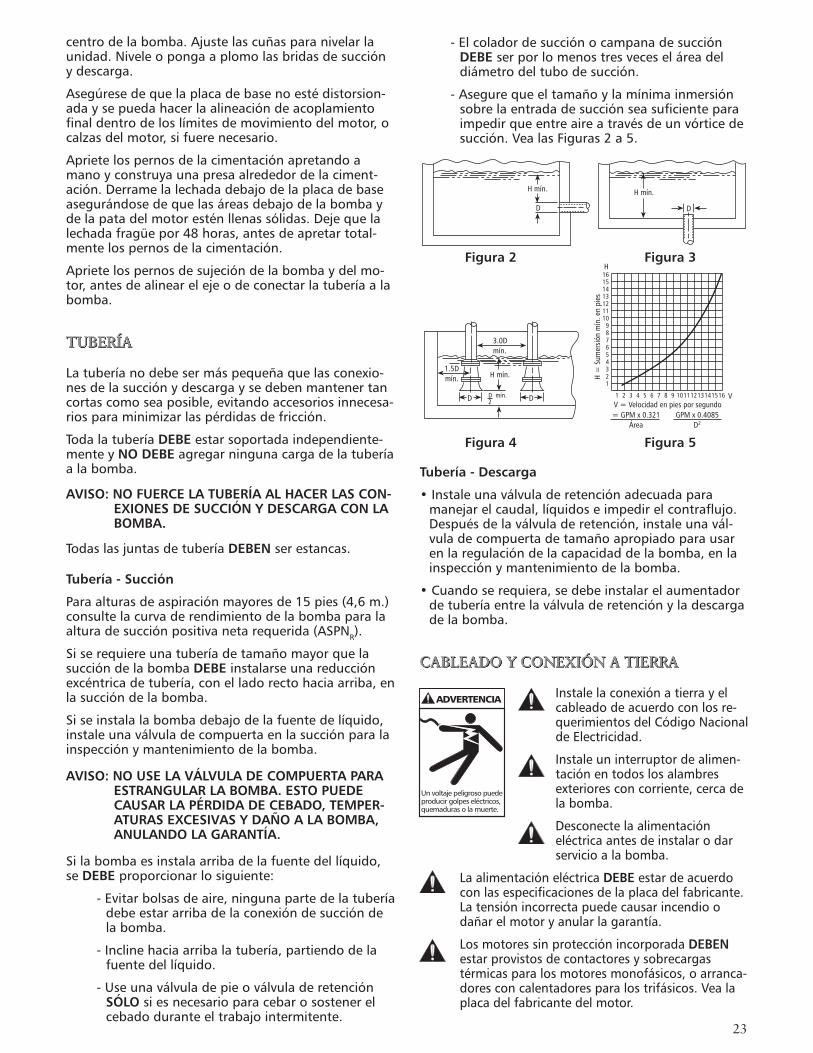
-ElcoladordesucciónocampanadesucciónDEBE serporlomenostresveceseláreadeldiámetrodeltubodesucción.
-Asegurequeeltamañoylamínimainmersiónsobrelaentradadesucciónseasuficienteparaimpedirqueentreaireatravésdeunvórticedesucción.VealasFiguras2a5.
Tubería - Descarga
•Instaleunaválvuladeretenciónadecuadaparamanejarelcaudal,líquidoseimpedirelcontraflujo.Despuésdelaválvuladeretención,instaleunavál-vuladecompuertadetamañoapropiadoparausarenlaregulacióndelacapacidaddelabomba,enlainspecciónymantenimientodelabomba.
•Cuandoserequiera,sedebeinstalarelaumentadordetuberíaentrelaválvuladeretenciónyladescargadelabomba.
CABLEADO Y CONEXIÓN A TIERRA
Instalelaconexiónatierrayelcableadodeacuerdoconlosre-querimientosdelCódigoNacionaldeElectricidad.
Instaleuninterruptordealimen-taciónentodoslosalambresexterioresconcorriente,cercadelabomba.
Desconectelaalimentacióneléctricaantesdeinstalarodarservicioalabomba.
LaalimentacióneléctricaDEBE estardeacuerdoconlasespecificacionesdelaplacadelfabricante.Latensiónincorrectapuedecausarincendioodañarelmotoryanularlagarantía.
LosmotoressinprotecciónincorporadaDEBEN estarprovistosdecontactoresysobrecargastérmicasparalosmotoresmonofásicos,oarranca-doresconcalentadoresparalostrifásicos.Vealaplacadelfabricantedelmotor.
centrodelabomba.Ajustelascuñasparanivelarlaunidad.Niveleopongaaplomolasbridasdesucciónydescarga.
Asegúresedequelaplacadebasenoestédistorsion-adaysepuedahacerlaalineacióndeacoplamientofinaldentrodeloslímitesdemovimientodelmotor,ocalzasdelmotor,sifuerenecesario.
Aprietelospernosdelacimentaciónapretandoamanoyconstruyaunapresaalrededordelaciment-ación.Derramelalechadadebajodelaplacadebaseasegurándosedequelasáreasdebajodelabombaydelapatadelmotoresténllenassólidas.Dejequelalechadafragüepor48horas,antesdeapretartotal-mentelospernosdelacimentación.
Aprietelospernosdesujecióndelabombaydelmo-tor,antesdealinearelejeodeconectarlatuberíaalabomba.
TUBERÍA
Latuberíanodebesermáspequeñaquelasconexio-nesdelasucciónydescargaysedebenmantenertancortascomoseaposible,evitandoaccesoriosinnecesa-riosparaminimizarlaspérdidasdefricción.
TodalatuberíaDEBE estarsoportadaindependiente-menteyNO DEBEagregarningunacargadelatuberíaalabomba.
AVISO: NO FUERCE LA TUBERÍA AL HACER LAS CON-EXIONES DE SUCCIÓN Y DESCARGA CON LA BOMBA.
TodaslasjuntasdetuberíaDEBEN serestancas.
Tubería - Succión
Paraalturasdeaspiraciónmayoresde15pies(4,6m.)consultelacurvaderendimientodelabombaparalaalturadesucciónpositivanetarequerida(ASPNR).
SiserequiereunatuberíadetamañomayorquelasuccióndelabombaDEBE instalarseunareducciónexcéntricadetubería,conelladorectohaciaarriba,enlasuccióndelabomba.
Siseinstalalabombadebajodelafuentedelíquido,instaleunaválvuladecompuertaenlasucciónparalainspecciónymantenimientodelabomba.
AVISO: NO USE LA VÁLVULA DE COMPUERTA PARA ESTRANGULAR LA BOMBA. ESTO PUEDE CAUSAR LA PÉRDIDA DE CEBADO, TEMPER-ATURAS EXCESIVAS Y DAÑO A LA BOMBA, ANULANDO LA GARANTÍA.
Silabombaesinstalaarribadelafuentedellíquido,seDEBE proporcionarlosiguiente:
-Evitarbolsasdeaire,ningunapartedelatuberíadebeestararribadelaconexióndesuccióndelabomba.
-Inclinehaciaarribalatubería,partiendodelafuentedellíquido.
-UseunaválvuladepieoválvuladeretenciónSÓLO siesnecesarioparacebarosostenerelcebadoduranteeltrabajointermitente.
H mín.
D D
H mín.
D D
1.5Dmín.
3.0Dmín.
H mín.
D mín.2
16151413121110
987654321
H =
Sum
ersió
n m
ín. e
n pi
es
H
1 2 3 4 5 6 7 8 9 10111213141516 VV = Velocidad en pies por segundo= GPM x 0.321
ÁreaGPM x 0.4085
D2
ADVERTENCIA
Unvoltajepeligrosopuedeproducirgolpeseléctricos,quemadurasolamuerte.
Figura 2 Figura 3
Figura 4 Figura 5
�4
Usesólocablesdecobrealmotoryatierra.ElalambreatierraDEBE serporlomenostangrandecomoelalam-brealmotor.Losalambresdebenserdecolorcodificadoparafacilitarelmantenimiento.
Sigacuidadosamenteeldiagramadelalambradodelfabricantedelmotorenlaplacadelfabricantedelmotoroenlatapaterminal.
LA OMISIÓN DE CONECTAR A TIERRA PERMANENTEMENTE LA BOMBA, EL MOTOR Y LOS CONTROLES, ANTES DE CONECTAR A LA ALIMENTACIÓN ELÉCTRICA, PUEDE CAUSAR CHOQUES, QUEMADURAS O LA MUERTE.
ALINEACIÓN DE ACOPLAMIENTO
LA OMISIÓN DE DESCONECTAR LA ALIMENTACIÓN ELÉCTRICA ANTES DE INTENTAR CUALQUIER MANTENIMIENTO PUEDE CAUSAR CHOQUES, QUEMADURAS O LA MUERTE.
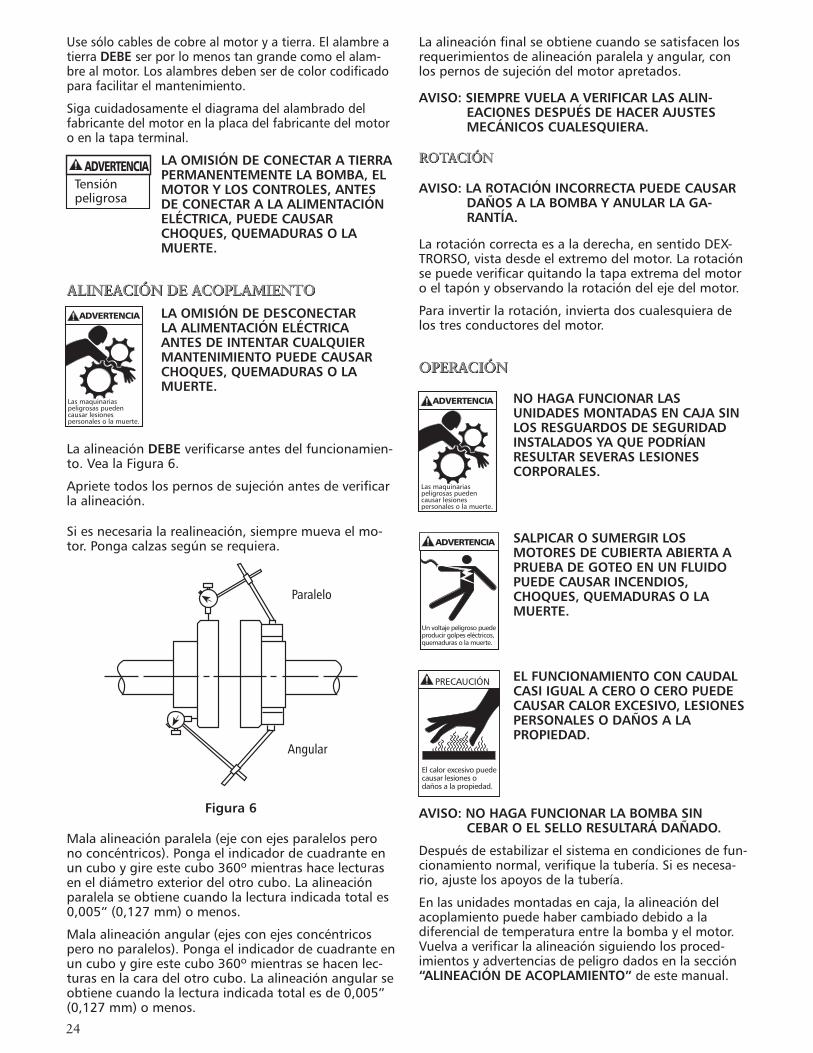
LaalineaciónDEBE verificarseantesdelfuncionamien-to.VealaFigura6.
Aprietetodoslospernosdesujeciónantesdeverificarlaalineación.
Siesnecesarialarealineación,siempremuevaelmo-tor.Pongacalzassegúnserequiera.
Figura 6
Malaalineaciónparalela(ejeconejesparalelosperonoconcéntricos).Pongaelindicadordecuadranteenuncuboygireestecubo360ºmientrashacelecturaseneldiámetroexteriordelotrocubo.Laalineaciónparalelaseobtienecuandolalecturaindicadatotales0,005”(0,127mm)omenos.
Malaalineaciónangular(ejesconejesconcéntricosperonoparalelos).Pongaelindicadordecuadranteenuncuboygireestecubo360ºmientrassehacenlec-turasenlacaradelotrocubo.Laalineaciónangularseobtienecuandolalecturaindicadatotalesde0,005”(0,127mm)omenos.
Laalineaciónfinalseobtienecuandosesatisfacenlosrequerimientosdealineaciónparalelayangular,conlospernosdesujecióndelmotorapretados.
AVISO: SIEMPRE VUELA A VERIFICAR LAS ALIN-EACIONES DESPUÉS DE HACER AJUSTES MECÁNICOS CUALESQUIERA.
ROTACIÓN
AVISO: LA ROTACIÓN INCORRECTA PUEDE CAUSAR DAÑOS A LA BOMBA Y ANULAR LA GA-RANTÍA.
Larotacióncorrectaesaladerecha,ensentidoDEX-TRORSO,vistadesdeelextremodelmotor.Larotaciónsepuedeverificarquitandolatapaextremadelmotoroeltapónyobservandolarotacióndelejedelmotor.
Parainvertirlarotación,inviertadoscualesquieradelostresconductoresdelmotor.
OPERACIÓN
NO HAGA FUNCIONAR LAS UNIDADES MONTADAS EN CAJA SIN LOS RESGUARDOS DE SEGURIDAD INSTALADOS YA QUE PODRÍAN RESULTAR SEVERAS LESIONES CORPORALES.
SALPICAR O SUMERGIR LOS MOTORES DE CUBIERTA ABIERTA A PRUEBA DE GOTEO EN UN FLUIDO PUEDE CAUSAR INCENDIOS, CHOQUES, QUEMADURAS O LA MUERTE.
EL FUNCIONAMIENTO CON CAUDAL CASI IGUAL A CERO O CERO PUEDE CAUSAR CALOR EXCESIVO, LESIONES PERSONALES O DAÑOS A LA PROPIEDAD.
AVISO: NO HAGA FUNCIONAR LA BOMBA SIN CEBAR O EL SELLO RESULTARÁ DAÑADO.
Despuésdeestabilizarelsistemaencondicionesdefun-cionamientonormal,verifiquelatubería.Siesnecesa-rio,ajustelosapoyosdelatubería.
Enlasunidadesmontadasencaja,laalineacióndelacoplamientopuedehabercambiadodebidoaladiferencialdetemperaturaentrelabombayelmotor.Vuelvaaverificarlaalineaciónsiguiendolosproced-imientosyadvertenciasdepeligrodadosenlasección“ALINEACIÓN DE ACOPLAMIENTO”deestemanual.
Tensiónpeligrosa
ADVERTENCIA
Lasmaquinariaspeligrosaspuedencausarlesionespersonalesolamuerte.
ADVERTENCIA
Parallel
Angular
Paralelo
Angular
ADVERTENCIA
Unvoltajepeligrosopuedeproducirgolpeseléctricos,quemadurasolamuerte.
PRECAUCIÓN
Elcalorexcesivopuedecausarlesionesodañosalapropiedad.
Lasmaquinariaspeligrosaspuedencausarlesionespersonalesolamuerte.
ADVERTENCIA
�5
MANTENIMIENTO
LA OMISIÓN DE DESCONECTAR LA ALIMENTACIÓN ELÉCTRICA ANTES DE INTENTAR CUALQUIER MANTENIMIENTO PUEDE CAUSAR CHOQUES, QUEMADURAS O LA MUERTE.
LA OMISIÓN DE ALIVIAR LA PRESIÓN DEL SISTEMA Y DRENAR EL SISTEMA ANTESDE INTENTAR CUALQUIER MANTENIMIENTO PUEDE CAUSAR DAÑOS A LA PROPIEDAD, LESIONES CORPORALES O LA MUERTE.
Unidades compactas:
Loscojinetesestánlocalizadosysonpartedelmotor.Parainformacióndelubricación,consultelasinstruc-cionesdelfabricantedelmotor.
Unidades montadas en caja:
Lascajasdecojinetedelasbombashansidoengrasa-dasporlavidadelcojinete.Noesposibleonecesariolubricarlas.
Sigalasinstruccionesdelubricacióndelfabricantedelmotorydelacoplamiento.
Servicio de temporada:
ParaRETIRAR labombadelservicio,quitetodoslostaponesdedrenajeydrenetodalatubería.
ParaDEVOLVER labombaalservicio,vuelvaaponertodoslostaponesusandocintaTeflon’oequivalente.
Reconectelalíneadesucciónsisequitó,examinelauniónyreparesiesnecesario.
Vuelvaacebaryhacerfuncionarlabombasiguiendotodaslasinstruccionesyadvertenciasenlasección“OPERACIÓN”deestemanual.
DESMONTAJE
SigaTODAS lasadvertenciaseinstruccionesdelasec-ción“MANTENIMIENTO”deestemanual.
Unidadescompactas,quitelospernosdesujecióndelmotor.
Unidadesmontadasencaja,quiteelresguardodelacoplamiento,elespaciador,elacoplamientoylospernosdesujecióndelacaja.
Extremo sumergido:
1.Quitelospernos(370)delacarcasa.
2.Quiteelconjuntodedesmontajedelacajaderodamientosdelacarcasa(100).
3.Quitelajuntadeempaque(351).Deséchela.
4.Enlasunidadescompactas,quiteeltapóndelex-tremodelmotorolatapaparaexponerlaranuradeldestornilladorolosfilosnormalesdelejeenelextremodelejedelmotor.
5.Mientrassujetaelejeconlaherramientaapro-piada(unidadescompactas)oconunallavedecorrea(unidadesmontadasencaja)quitelatuerca(304)delimpulsorgirandoensentidoSINISTROR-SO.Latuercadelimpulsorpuedenecesitarquesecalienteconunaantorchaparaquitarla.
AVISO: TENGA CUIDADO CUANDO MANEJE LA TUERCA CALIENTE DEL IMPULSOR.
6.Mientrassujetaeleje,quiteelimpulsor(101)girandoensentidoSINISTRORSO.Elimpulsorpuedequesenecesitecalentarparaquitarlo.
AVISO: TENGA CUIDADO CUANDO MANEJE UN IM-PULSOR CALIENTE.
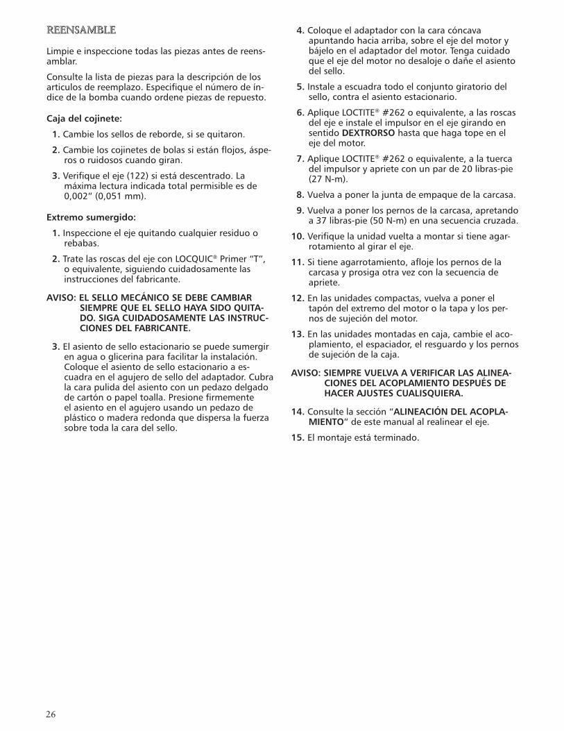
7.Usandodosdestornilladores,hagapalancagirandolaseccióndelconjunto(383)delsellomecánico.Deseche.VealaFigura7.
Figura7
8.Quitelospernos(371)deladaptadoryeladapta-dor(108),tirandoconésteelasientoestacionariodelsellomecánico.
9.Presionehaciaafueraelasientoestacionariodelsellomecánicodelladodelmotordeladaptador.Deséchelo.
Caja del cojinete:
1.Quitelatapadelcojinete(109).
2.Quiteelanillodesujeción(361).
3.Quiteelconjuntodelejedelacaja.
4.Siestádesgastadoodañado,quitelossellosdereborde(138,139)delacajadelcojinete(228)ylatapadelcojinete(109).
5.Useunextractordecojineteoprensadelejeparaquitarelcojinetedebolas(112,168).
ADVERTENCIA
Unvoltajepeligrosopuedeproducirgolpeseléctricos,quemadurasolamuerte.
ADVERTENCIA
Latensiónpeligrosapuedecausarchoques,quemadurasolamuerte.
�6
NotasREENSAMBLE
Limpieeinspeccionetodaslaspiezasantesdereens-amblar.
Consultelalistadepiezasparaladescripcióndelosarticulosdereemplazo.Especifiqueelnúmerodeín-dicedelabombacuandoordenepiezasderepuesto.
Caja del cojinete:
1.Cambielossellosdereborde,sisequitaron.
2.Cambieloscojinetesdebolassiestánflojos,áspe-rosoruidososcuandogiran.
3.Verifiqueeleje(122)siestádescentrado.Lamáximalecturaindicadatotalpermisibleesde0,002”(0,051mm).
Extremo sumergido:
1.Inspeccioneelejequitandocualquierresiduoorebabas.
2.TratelasroscasdelejeconLOCQUIC®Primer“T”,oequivalente,siguiendocuidadosamentelasinstruccionesdelfabricante.
AVISO: EL SELLO MECÁNICO SE DEBE CAMBIAR SIEMPRE QUE EL SELLO HAYA SIDO QUITA-DO. SIGA CUIDADOSAMENTE LAS INSTRUC-CIONES DEL FABRICANTE.
3.Elasientodeselloestacionariosepuedesumergirenaguaoglicerinaparafacilitarlainstalación.Coloqueelasientodeselloestacionarioaes-cuadraenelagujerodesellodeladaptador.Cubralacarapulidadelasientoconunpedazodelgadodecartónopapeltoalla.Presionefirmementeelasientoenelagujerousandounpedazodeplásticoomaderaredondaquedispersalafuerzasobretodalacaradelsello.
4.Coloqueeladaptadorconlacaracóncavaapuntandohaciaarriba,sobreelejedelmotorybájeloeneladaptadordelmotor.Tengacuidadoqueelejedelmotornodesalojeodañeelasientodelsello.
5.Instaleaescuadratodoelconjuntogiratoriodelsello,contraelasientoestacionario.
6.ApliqueLOCTITE®#262oequivalente,alasroscasdelejeeinstaleelimpulsorenelejegirandoensentidoDEXTRORSO hastaquehagatopeenelejedelmotor.
7.ApliqueLOCTITE®#262oequivalente,alatuercadelimpulsoryaprieteconunparde20libras-pie(27N-m).
8.Vuelvaaponerlajuntadeempaquedelacarcasa.
9.Vuelvaaponerlospernosdelacarcasa,apretandoa37libras-pie(50N-m)enunasecuenciacruzada.
10.Verifiquelaunidadvueltaamontarsitieneagar-rotamientoalgirareleje.
11.Sitieneagarrotamiento,aflojelospernosdelacarcasayprosigaotravezconlasecuenciadeapriete.
12.Enlasunidadescompactas,vuelvaaponereltapóndelextremodelmotorolatapaylosper-nosdesujecióndelmotor.
13.Enlasunidadesmontadasencaja,cambieelaco-plamiento,elespaciador,elresguardoylospernosdesujecióndelacaja.
AVISO: SIEMPRE VUELVA A VERIFICAR LAS ALINEA-CIONES DEL ACOPLAMIENTO DESPUÉS DE HACER AJUSTES CUALISQUIERA.
14.Consultelasección“ALINEACIÓN DEL ACOPLA-MIENTO”deestemanualalrealineareleje.
15.Elmontajeestáterminado.
�7
100 101 383 408 108
371370381304358
Opciones de sello mecánico Equipo Servicio Giratorio Estacionario Elastómeros Partes metálicas
Estándar General Cerámica BUNA-N
Serviciopesado Carbono ResistenteNi. BUNA-N Aceroinoxidable, Opcional Altatemperatura ResistenteNi. EPR Serie300
Químico Cerámica Viton
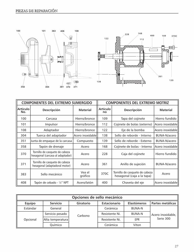
PIEZAS DE REPARACIÓN
COMPONENTES DEL EXTREMO SUMERGIDO COMPONENTES DEL EXTREMO MOTRIZ
Artículo Artículo No. Descripción Material no Descripción Material
100 Carcasa Hierro/bronce 109 Tapadelcojinete Hierrofundido
101 Impulsor Hierro/bronce 112 Cojinetedebolas(externo) Aceroinoxidable
108 Adaptador Hierro/bronce 122 Ejedelabomba Aceroinoxidable
304 Tuercadeladaptador Aceroinoxidable 138 Sellodereborde-Interno BUNA-N/acero
351 Juntadeempaquedelacarcasa Compuesto 139 Sellodereborde-Externo BUNA-N/acero
358 Tapóndedrenaje Acero 168 Cojinetedebolas-Interno Aceroinoxidable
370 Tornillodecasquetedecabeza Acero 228 Cajadelcojinete Hierrofundido hexagonal(carcasaaladaptador)
371 Tornillodecasquetedecabeza Acero 361 Anillodesujeción BUNA-N/acero hexagonal(adaptadoralmotor)
383 Sellomecánico Veael 370C Tornillodecasquetedecabeza Acero gráfico hexagonal(cajaalatapa)
408 Tapóndecebado-¼”NPT Acero/latón 400 Chavetadeleje Aceroinoxidable
361
138
122
228 168
112
400 109 370C
139
�8
INVESTIGACIÓN DE AVERÍAS
LA OMISIÓN DE DESCONECTAR LA ALIMENTACIÓN ELÉCTRICA ANTES DE INTENTAR CUALQUIER MANTENIMIENTO PUEDE CAUSAR CHOQUES, QUEMADURAS O LA MUERTE.
SÍNTOMA:
Motor no funciona: Vealascausasprobablesdel1al5.
Entrega poco o nada de líquido: Vealascausasprobables6a13.
Consumo excesivo de corriente: Vealascausasprobables:3,13,14,15.
Excesivo ruido y vibraciones: Vealascausasprobables:3,6,7,10,12,14,16Y17.
CAUSAS PROBABLES:
1. Protectortérmicodelmotordisparado.2. Interruptorautomáticoabiertoofundidoel
fusible.3. Impulsorconagarrotamiento.4. Motormalconectado.5. Motordefectuoso.6. Bombanoestácebada,hayaireogasesenel
líquidobombeado.7. Taponadaladescarga,succiónocerradala
válvula.8. Rotaciónincorrecta.(Solotrifásico).9. Bajatensiónopérdidadefase.10. Impulsordesgastadootaponado.11. Demasiadoaltalaalturaocargadelsistema.12. DemasiadobajalaASPND(alturadesucción
positivanetadisponible)-excesivalaalturadeaspiraciónolaspérdidas.
13. Incorrectoeldiámetrodelimpulsor.14. Demasiadobajalaalturadedescarga-caudales
excesivos.15. Demasiadoaltalaviscosidaddelfluido,la
gravedadespecífica.16. Cojinetedesgastado.17. Bomba,motorotuberíaflojos.
ADVERTENCIA
Unvoltajepeligrosopuedeproducirgolpeseléctricos,quemadurasolamuerte.
GARANTÍA LIMITADA DE GOULDS PUMPSEsta garantía es aplicable a todas las bombas para sistemas de agua fabricadas por Goulds Pumps.Toda parte o partes que resulten defectuosas dentro del período de garantía serán reemplazadas sin cargo para el comerciante durante dicho período de garantía. Tal período de garantía se extiende por doce (1�) meses a partir de la fecha de instalación, o dieciocho (18) meses a partir de la fecha de fabricación, cualquiera se cumpla primero.Todo comerciante que considere que existe lugar a un reclamo de garantía deberá ponerse en contacto con el distribuidor autorizado de Goulds Pumps del cual adquiriera la bomba, y ofrecer información detallada con respecto al reclamo. El distribuidor está autorizado a liquidar todos los reclamos por garantía a través del Departamento de Servicios a Clientes de Goulds Pumps.La presente garantía excluye:(a) La mano de obra, el transporte y los costos relacionados en los que incurra el comerciante;(b) los costos de reinstalación del equipo reparado;(c) los costos de reinstalación del equipo reemplazado;(d) daños emergentes de cualquier naturaleza; y(e) el reembolso de cualquier pérdida causada por la interrupción del servicio.A los fines de esta garantía, los términos “Distribuidor”, “Comerciante” y “Cliente” se definen como sigue:(1) “Distribuidor” es aquel individuo, sociedad, corporación, asociación u otra entidad jurídica que opera entre Goulds Pumps y el comerciante para la compra, consignación o contratos de venta de las bombas en cuestión.(�) “Comerciante” es todo individuo, sociedad, corporación, asociación u otra entidad jurídica que realiza negocios de venta o alquiler-venta (leasing) de bombas a clientes.(3) “Cliente” es toda entidad que compra o que adquiere bajo la modalidad de leasing las bombas en cuestión de un comerciante. El término “cliente” puede significar un individuo, una sociedad, una corporación, una sociedad de responsabilidad limitada, una asociación o cualquier otra entidad jurídica con actividades en cualquier tipo de negocios.
LA PRESENTE GARANTÍA SE EXTIENDE AL COMERCIANTE ÚNICAMENTE
�9
Declaration of ConformityWe at,Goulds Pumps/ITT Industries1 Goulds DriveAuburn, NY 130�1Declare that the following products: NPE, MCS, MCC, 3656, 3656 SP, GB, SSV, SVI, NPO, Prime Line SP, HB, HMS, LC, NPV, LB, LBS comply with Machine Directive 98/37/EC. This equipment is intended to be incorporated with machinery covered by this directive, but must not be put into service until the machinery into which it is to be incorporated has been declared in conformity with the actual provisions of the directive.
Declaración de ConformidadNosotros enGoulds Pumps/ITT Industries1 Goulds DriveAuburn, NY 130�1Declaramos que los siguientes productos: NPE, MCS, MCC, 3656, 3656 SP, GB, SSV, SVI, NPO, Prime Line SP, HB,NPE, MCS, MCC, 3656, 3656 SP, GB, SSV, SVI, NPO, Prime Line SP, HB, HMS, LC, NPV, LB, LBS cumplen con las Directivas para Maquinarias 98/37/EC. Este equipo ha sido diseñado para cumplen con las Directivas para Maquinarias 98/37/EC. Este equipo ha sido diseñado para ser incorporado a la maquinaria cubierta por esta directiva pero no debe ponerse en funcionamiento hasta que se declare que la maquinaria en la que será incorporado cumple con las disposiciones reales de la directiva.
Déclaration de ConformitéNous, àGoulds Pumps, ITT Industries1 Goulds DriveAuburn, NY, U.S.A. 130�1,déclarons que les produits NPE, MCS, MCC, 3656, 3656 SP, GB, SSV, SVI, NPO, Prime Line SP, HB, HMS, LC, NPV, LB et LBS sont conformes à la directive 98/37/CE (législation relative aux machines). Ils sont destinés à être intégrés dans la machinerie faisant l’objet de ladite directive, mais ne doivent pas être mis en service tant que la machinerie en question ne sera pas déclarée conforme aux stipulations de la directive.
Declaration of Conformity
Declaración de Conformidad
Déclaration de Conformité
James M. AlloccoProduct Manager/
Encargado de producto/Directeur des produits

30
NOTES/NOTAS

31
NOTES/NOTAS
3�
ITT
Goulds Pumps, G&L y el símbolo ITT Engineered Blocks son marcas registradas y marcas comerciales de ITT Corporation.
Loctite y Locquic son marcas registradas de Loctite Corporation.
LAS ESPECIFICACIONES ESTÁN SUJETAS A CAMBIO SIN PREVIO AVISO.
IM007R04 Septiembre, 2006© 2006 ITT Corporation
Engineered for life
Agua Industrial