Embed Size (px)
Citation preview
MATERIALS DESIGN LABORATORY
Deformation Mechanisms in
Intercritically Annealed
Medium Mn Steel
B.C. DE COOMAN, Sunmi SHIN, Seon Jong LEE, Dongyeol LEE (GIFT)
Hyoung Seop KIM, Marat LATYPOV (Materials Science and Engineering)
Pohang University of Science and Technology
Pohang, Republic of Korea
Oct 25-29, 2015, Jeju Island
MATERIALS DESIGN LABORATORY
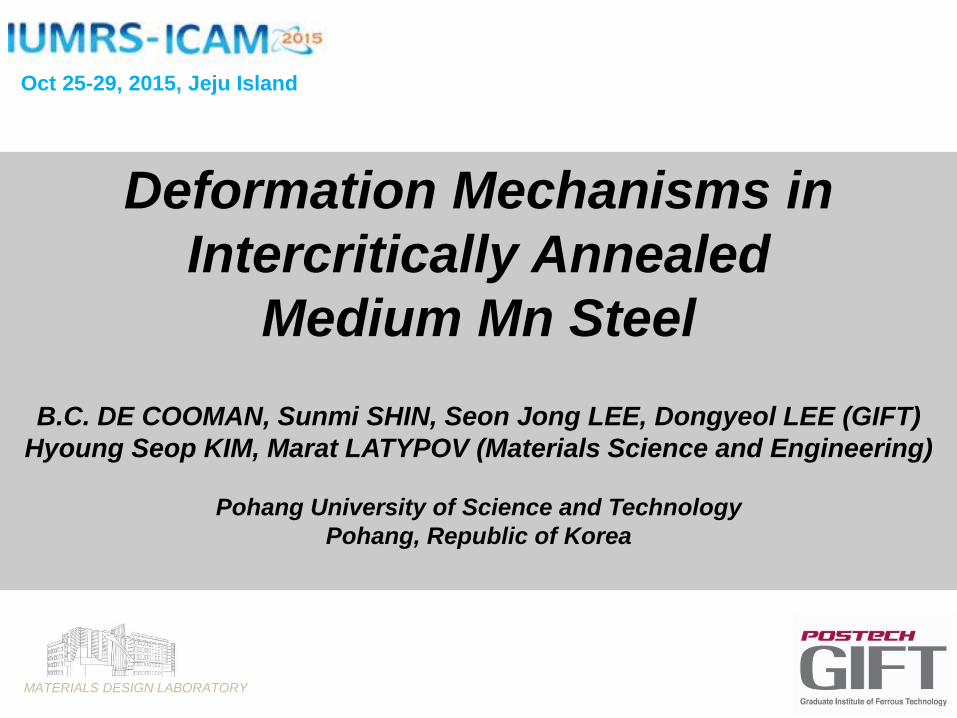
Golf 2 (1983-1992) Golf 7 (2014)
Issue #2:
Greenhouse gas emissions
Issue #1:
Passenger safety
2015: 130 g CO2 /km → 2020: 95 g CO2 /km
2015: 17 km/l → 2020: 25 km/lIssue #3:
Fuel efficiency
Introduction
MATERIALS DESIGN LABORATORY
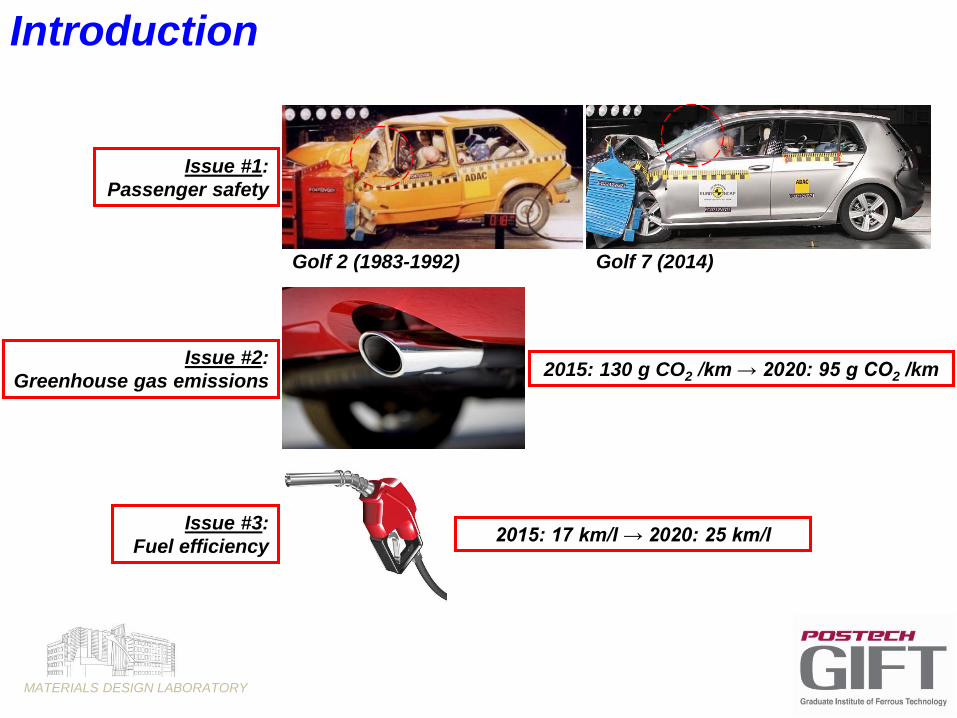
Properties
Processing
Microstructure
PerformanceProperties
Processing
Microstructure
Performance
COST
Regulations
Steel
Unibody
Aluminum
Space frame
CFRC
Skeleton
Introduction
Al-alloy body
Steel frame
MATERIALS DESIGN LABORATORY
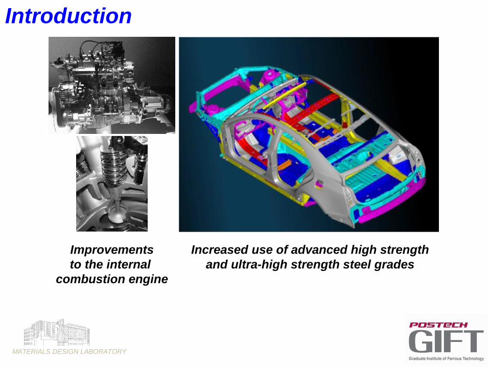
Improvements
to the internal
combustion engine
Increased use of advanced high strength
and ultra-high strength steel grades
Introduction

MATERIALS DESIGN LABORATORY
6% HPF + 5% MA
23%
HSS
30%
DP / Multi Phase
34%
IF
+LC
+BH
Cadillac CTS
PHS VW:
6% (GOLF 6)
28% (GOLF 7)
Automotive Body Materials Evolution

MATERIALS DESIGN LABORATORY
0 5 10 15 20 250
500
1000
1500
2000
2500
En
gin
ee
rin
g S
tres
s, M
Pa
Engineering Strain, %
Al
Al+HPF
Al+HPF+BH
0 5 10 15 20 250
500
1000
1500
2000
2500
En
gin
ee
rin
g S
tres
s, M
Pa
Engineering Strain, %
Al
Al+HPF
Al+HPF+BH
Aluminized PHS, 2nd WeekAluminized PHS, 1st Week
2GPa Press Hardening Steel
F+P F+P
CA (F+P) CA+HPF CA+HPF+BH
MATERIALS DESIGN LABORATORY
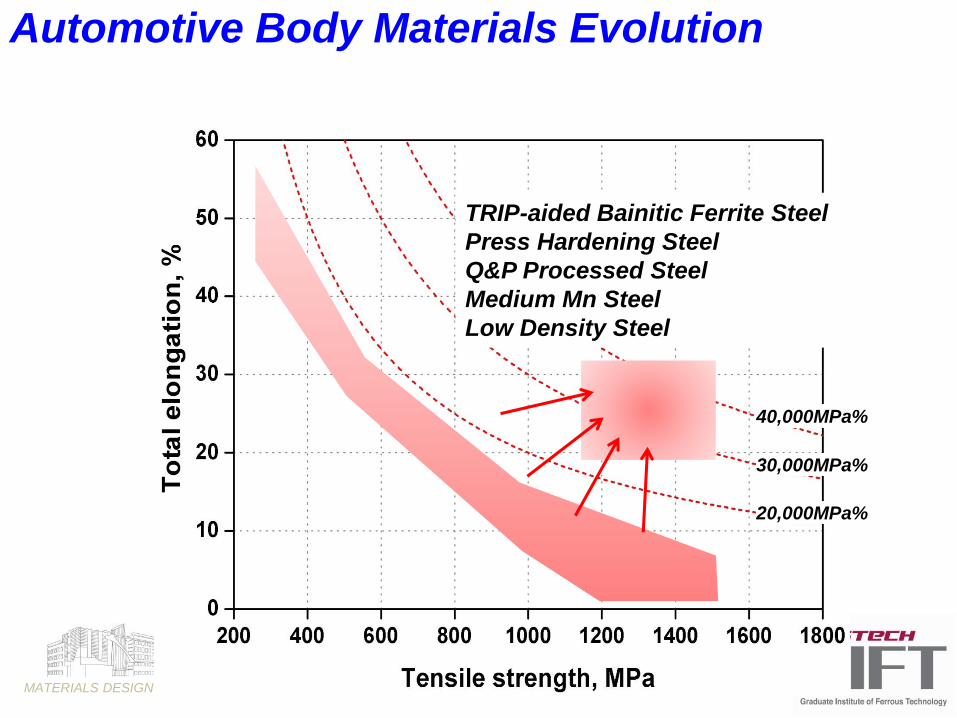
40,000MPa%
20,000MPa%
30,000MPa%
TRIP-aided Bainitic Ferrite Steel
Press Hardening Steel
Q&P Processed Steel
Medium Mn Steel
Low Density Steel
Automotive Body Materials Evolution
MATERIALS DESIGN LABORATORY
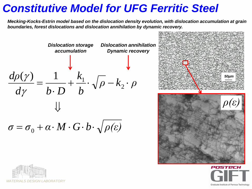
Mecking-Kocks-Estrin model based on the dislocation density evolution, with dislocation accumulation at grain
boundaries, forest dislocations and dislocation annihilation by dynamic recovery.
ρ(ε)bGMασσ
ρkρb
k
Dbd
dρ
0
21
1)(
Constitutive Model for UFG Ferritic Steel
50µm
ρ(ε)
Dislocation storage
accumulation
Dislocation annihilation
Dynamic recovery

MATERIALS DESIGN LABORATORY
10+10
10+11
10+12
10+13
10+14
10+15
0.0 0.1 0.2 0.3 0.4 0.5 0.6
Grain size 1mm
True strain
Dis
locati
on
den
sit
y,
m-2
0
200
400
600
800
1000
0.0 0.1 0.2 0.3 0.4 0.5 0.6
True strainT
rue s
tress,
MP
a
Str
ain
hard
en
ing
, M
Pa
Constitutive Model for UFG Ferritic Steel
MATERIALS DESIGN LABORATORY
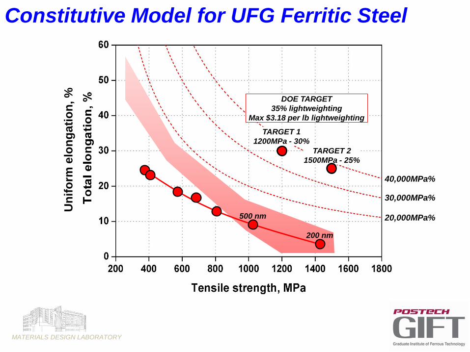
20,000MPa%
30,000MPa%
TARGET 1
1200MPa - 30%
TARGET 2
1500MPa - 25%
500 nm
200 nm
40,000MPa%
Un
ifo
rm e
lon
gati
on
, %
Constitutive Model for UFG Ferritic Steel
DOE TARGET
35% lightweighting
Max $3.18 per lb lightweighting

MATERIALS DESIGN LABORATORY
)()(
)0
bG
(εbGαMσσ(ε)
o
D
k
df
X
T
y
precprecprec
is
p
o
),(
)(
),(
parameterPetch Hall:
constanton Annihilati:
constanton Accumulati :
parameter Grainsize :
sizet size/PackeGrain :
ingstrengthensolution Solid :
ingstrengthenion Precipitat :
stress Peierls :
eTemperatur:
modulusShear :
vectorBurgers:
strainratestrain,: ,
densityn dislocatio:)(
2
1
y
s
prec
P
k
k
k
P
D
T
G
b
Ferrite
Martensite
Austenite
Twins
0D
111 D
ρkρb
k
bd
dρ
2
11)(
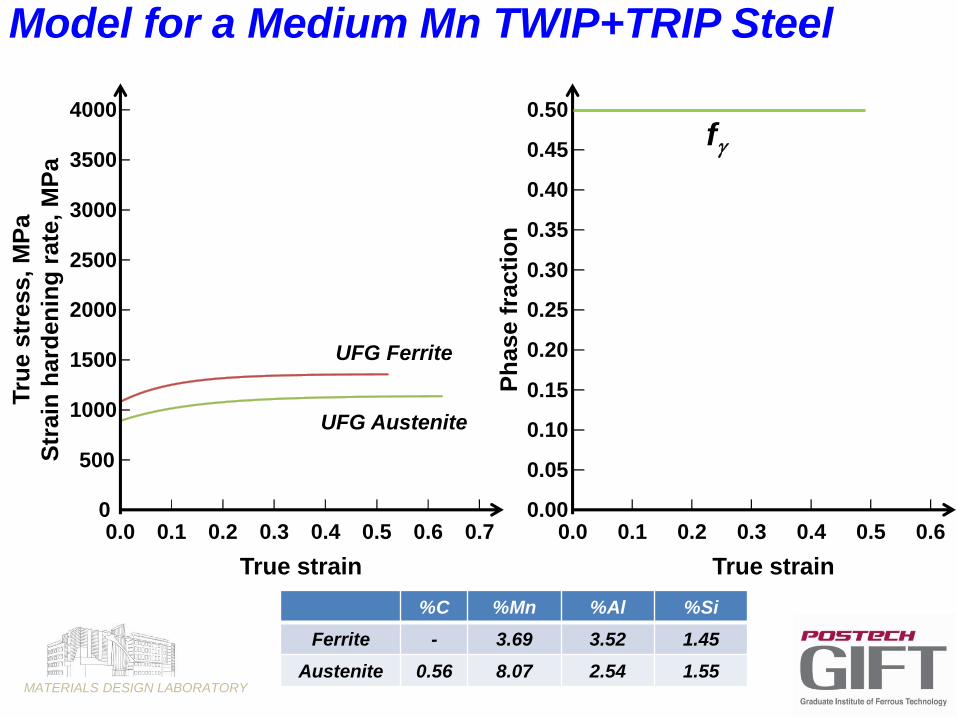
Model for a Medium Mn TWIP+TRIP Steel
MATERIALS DESIGN LABORATORY
0.00
0.05
0.10
0.15
0.20
0.25
0.30
0.35
0.40
0.45
0.50
0.0 0.1 0.2 0.3 0.4 0.5 0.6P
hase f
racti
on
True strain
f
0
500
1000
1500
2000
2500
3000
3500
4000
0.0 0.1 0.2 0.3 0.4 0.5 0.6 0.7
True strain
Tru
e s
tress,
MP
a
Str
ain
hard
en
ing
rate
, M
Pa
UFG Ferrite
UFG Austenite
%C %Mn %Al %Si
Ferrite - 3.69 3.52 1.45
Austenite 0.56 8.07 2.54 1.55
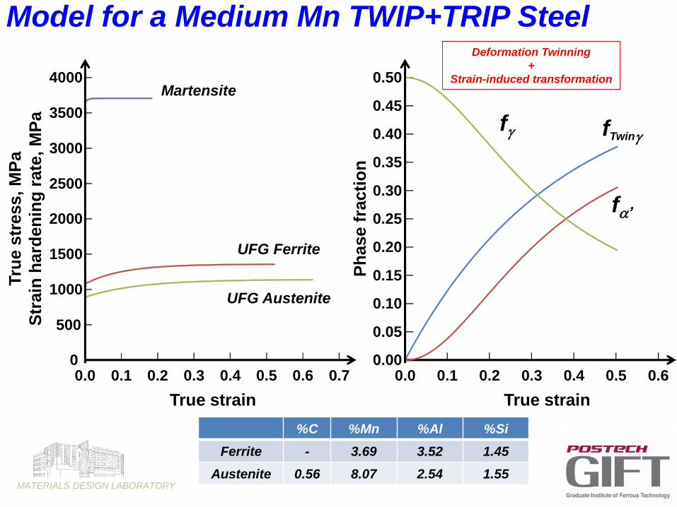
Model for a Medium Mn TWIP+TRIP Steel
MATERIALS DESIGN LABORATORY
0.00
0.05
0.10
0.15
0.20
0.25
0.30
0.35
0.40
0.45
0.50
0.0 0.1 0.2 0.3 0.4 0.5 0.6P
hase f
racti
on
True strain
f fTwin
f’
0
500
1000
1500
2000
2500
3000
3500
4000
0.0 0.1 0.2 0.3 0.4 0.5 0.6 0.7
True strain
Tru
e s
tress,
MP
a
Str
ain
hard
en
ing
rate
, M
Pa
Martensite
UFG Ferrite
UFG Austenite
%C %Mn %Al %Si
Ferrite - 3.69 3.52 1.45
Austenite 0.56 8.07 2.54 1.55
Deformation Twinning
+
Strain-induced transformation
Model for a Medium Mn TWIP+TRIP Steel

MATERIALS DESIGN LABORATORY
0.00
0.05
0.10
0.15
0.20
0.25
0.30
0.35
0.40
0.45
0.50
0.0 0.1 0.2 0.3 0.4 0.5 0.6P
hase f
racti
on
True strain
f fTwin
f’
0
500
1000
1500
2000
2500
3000
3500
4000
0.0 0.1 0.2 0.3 0.4 0.5 0.6 0.7
True strain
Tru
e s
tress,
MP
a
Str
ain
hard
en
ing
rate
, M
Pa
Martensite
UFG Ferrite
UFG Austenite
)(
d
d )(
%C %Mn %Al %Si
Ferrite - 3.69 3.52 1.45
Austenite 0.56 8.07 2.54 1.55
Model for a Medium Mn TWIP+TRIP Steel

MATERIALS DESIGN LABORATORY
0.00
0.05
0.10
0.15
0.20
0.25
0.30
0.35
0.40
0.45
0.50
0.0 0.1 0.2 0.3 0.4 0.5 0.6P
hase f
racti
on
True strain
f fTwin
f’
0
500
1000
1500
2000
2500
3000
3500
4000
0.0 0.1 0.2 0.3 0.4 0.5 0.6 0.7
True strain
Tru
e s
tress,
MP
a
Str
ain
hard
en
ing
rate
, M
Pa
)(
d
d )(
%C %Mn %Al %Si
Ferrite - 3.69 3.52 1.45
Austenite 0.56 8.07 2.54 1.55
+0.1% V
Model for a Medium Mn TWIP+TRIP Steel
MATERIALS DESIGN LABORATORY
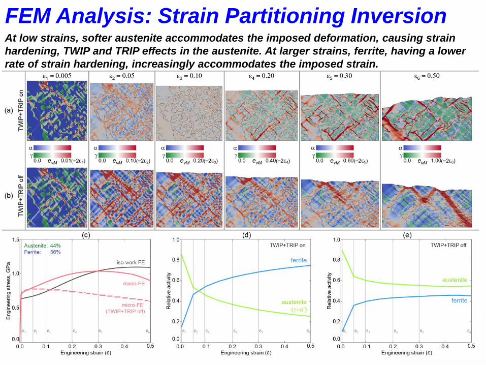
FEM Analysis: Strain Partitioning InversionAt low strains, softer austenite accommodates the imposed deformation, causing strain
hardening, TWIP and TRIP effects in the austenite. At larger strains, ferrite, having a lower
rate of strain hardening, increasingly accommodates the imposed strain.
MATERIALS DESIGN LABORATORY
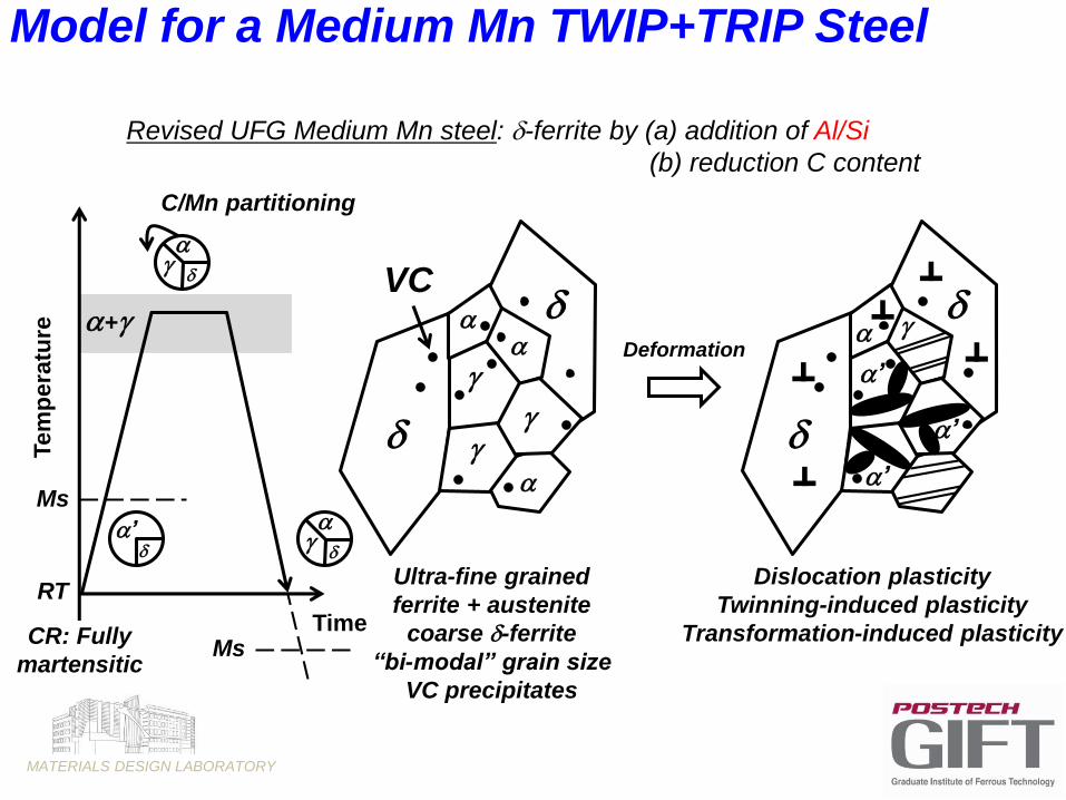
Revised UFG Medium Mn steel: d-ferrite by (a) addition of Al/Si
(b) reduction C content
Deformation
Dislocation plasticity
Twinning-induced plasticity
Transformation-induced plasticity
Ultra-fine grained
ferrite + austenite
coarse d-ferrite
“bi-modal” grain size
VC precipitates
d
d
d
d
’
’
’
Tem
pe
ratu
re
Ms
RT
’
CR: Fully
martensitic
+
dd
d
C/Mn partitioning
TimeMs
VC
Model for a Medium Mn TWIP+TRIP Steel

MATERIALS DESIGN LABORATORY
TWIP Steel
Fully Austenitic Microstructure
Coarse grained
Mechanical twinning
From TWIP to TWIP+TRIP Steel
5μm
TWIP steel
γ
500nm
8Mn HR TWIP+TRIP steel
α
γα
γ
Medium Mn TWIP+TRIP Steel
Austeno-Ferritic Microstructure
Ultra-fine grained
Mechanical twinning + Strain-induced Transformation
MATERIALS DESIGN LABORATORY
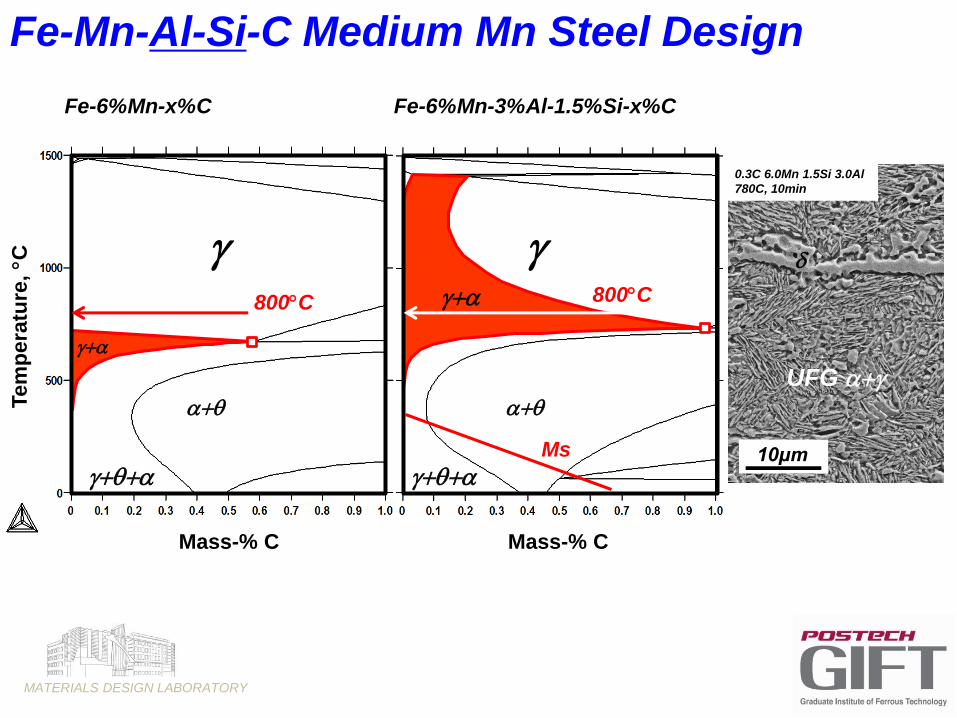
q
q
800C
Fe-6%Mn-x%C Fe-6%Mn-3%Al-1.5%Si-x%C
q
q
800C
Fe-Mn-Al-Si-C Medium Mn Steel Design
0.3C 6.0Mn 1.5Si 3.0Al
780C, 10min
d
UFG
10μmMs
Mass-% C Mass-% C
Tem
pera
ture
, C
MATERIALS DESIGN LABORATORY
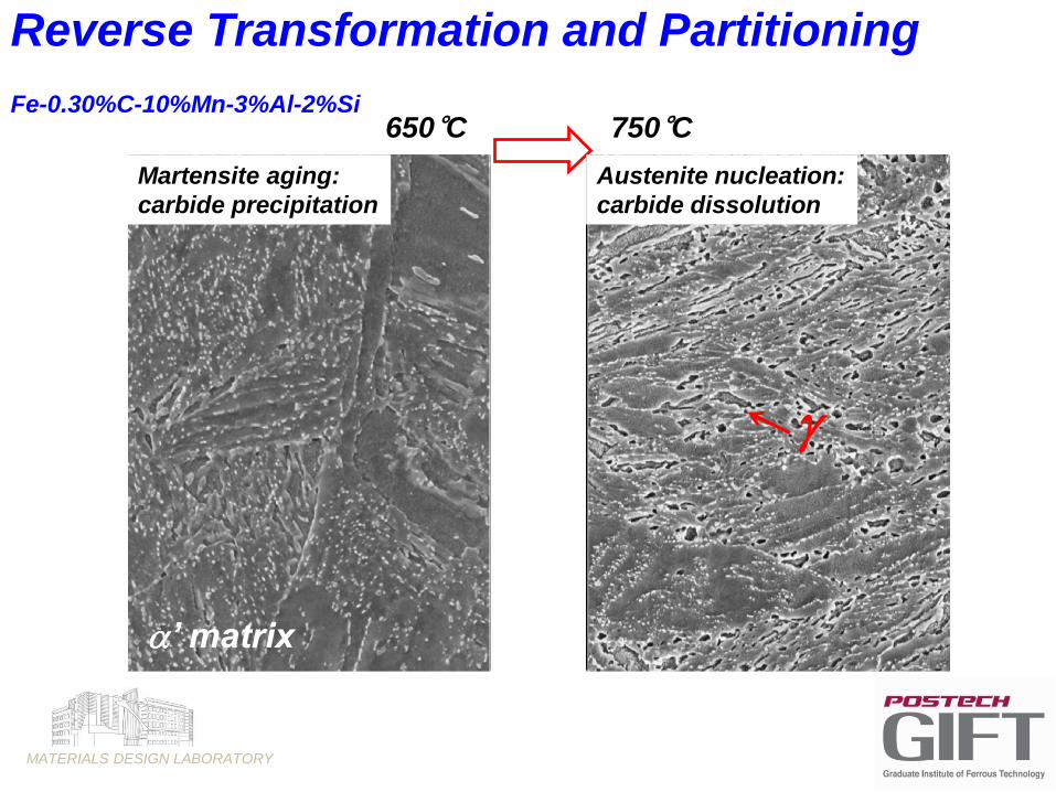
Fe-0.30%C-10%Mn-3%Al-2%Si750°C650°C
’ matrix
Martensite aging:
carbide precipitation
Reverse Transformation and Partitioning
Austenite nucleation:
carbide dissolution
MATERIALS DESIGN LABORATORY
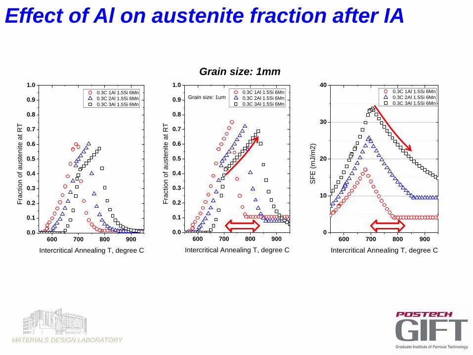
Effect of Al on austenite fraction after IA
600 700 800 9000.0
0.1
0.2
0.3
0.4
0.5
0.6
0.7
0.8
0.9
1.0
Grain size: 1um 0.3C 1Al 1.5Si 6Mn
0.3C 2Al 1.5Si 6Mn
0.3C 3Al 1.5Si 6Mn
Fra
ctio
n o
f a
uste
nite
at
RT
Intercritical Annealing T, degree C
600 700 800 9000.0
0.1
0.2
0.3
0.4
0.5
0.6
0.7
0.8
0.9
1.0 0.3C 1Al 1.5Si 6Mn
0.3C 2Al 1.5Si 6Mn
0.3C 3Al 1.5Si 6Mn
Fra
ctio
n o
f a
uste
nite
at
RT
Intercritical Annealing T, degree C
Grain size: 1mm
600 700 800 9000
10
20
30
40 0.3C 1Al 1.5Si 6Mn
0.3C 2Al 1.5Si 6Mn
0.3C 3Al 1.5Si 6Mn
SF
E (
mJ/m
2)
Intercritical Annealing T, degree C
MATERIALS DESIGN LABORATORY
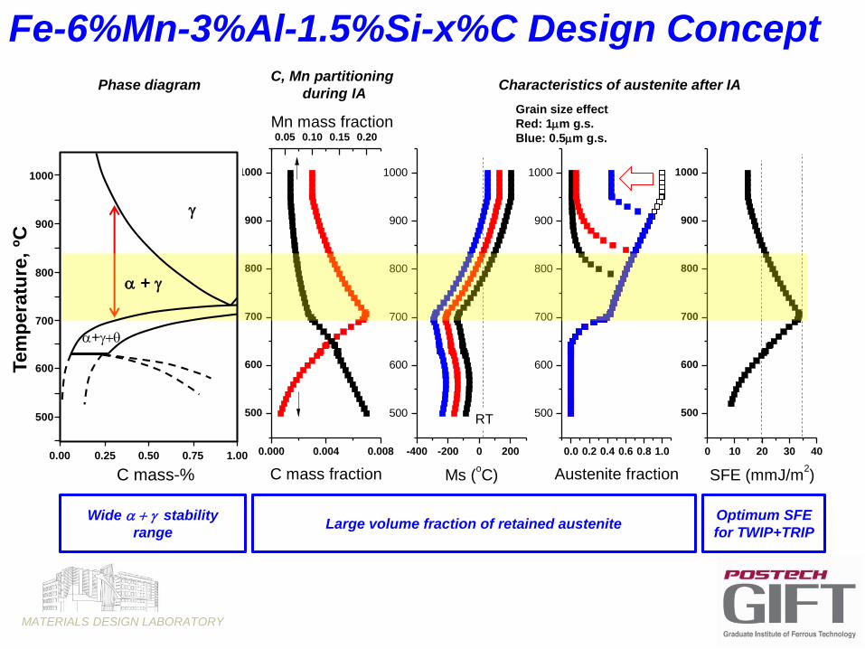
0.000 0.004 0.008
500
600
700
800
900
1000
Tem
pera
ture
(oC
)
C mass fraction
-400 -200 0 200
500
600
700
800
900
1000
Ms (oC)
RT
0.0 0.2 0.4 0.6 0.8 1.0
500
600
700
800
900
1000
Austenite fraction
0 10 20 30 40
500
600
700
800
900
1000
SFE (mmJ/m2)
0.05 0.10 0.15 0.20
Mn mass fraction
Characteristics of austenite after IAPhase diagram
Grain size effect
Red: 1mm g.s.
Blue: 0.5mm g.s.
C, Mn partitioning
during IA
+q
+
Tem
pera
ture
, ºC
C mass-%
1.000.750.500.250.00
500
600
700
800
900
1000
Wide stability
rangeLarge volume fraction of retained austenite
Optimum SFE
for TWIP+TRIP
Fe-6%Mn-3%Al-1.5%Si-x%C Design Concept
MATERIALS DESIGN LABORATORY
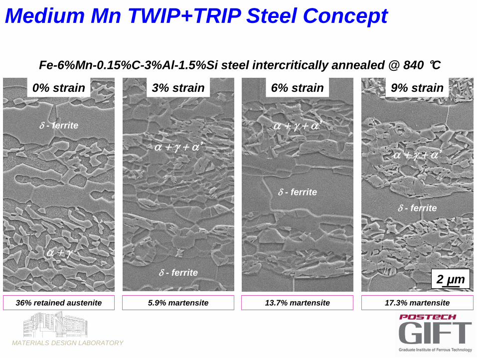
Fe-6%Mn-0.15%C-3%Al-1.5%Si steel intercritically annealed @ 840 °C
Medium Mn TWIP+TRIP Steel Concept
d - ferrite
0% strain
36% retained austenite
3% strain
d - ferrite
’
5.9% martensite
6% strain
d - ferrite
’
13.7% martensite
9% strain
d - ferrite
’
2 μm
17.3% martensite

MATERIALS DESIGN LABORATORY
10mm
d
d
d
200nm
200nm
50nm
50nm
Ferrite
Austenite
VC
SF
V-added UFG Medium Mn Steel
800ppmC 6%Mn 1.5%Si 2%Al

MATERIALS DESIGN LABORATORY
Fe-8%Mn-3%Al-2%Si-0.4%C-0.2%V
Intercritically Annealed @ 750C, 600 s
VC-precipitate
Ferrite
Austenite
Ferrite
VC-precipitate
Ferrite
Austenite
FerritePrecipitate
formation
Partitioning

MATERIALS DESIGN LABORATORY
0.2 μm
2 1/nm2 1/nm
0.2 μm
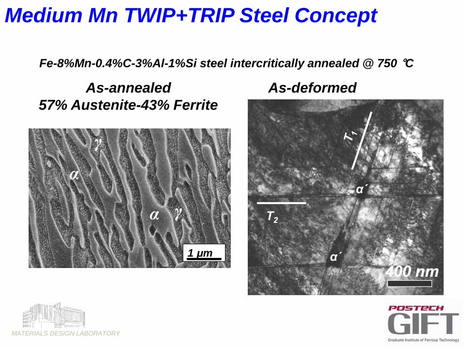
Fe-8%Mn-0.4%C-3%Al-1%Si steel intercritically annealed @ 750 °C
Medium Mn TWIP+TRIP Steel Concept
Fe-5%Mn-0.3%C-3%Al-1.5%Si steel intercritically annealed @ 800 °C
6
MATERIALS DESIGN LABORATORY
As-annealed
57% Austenite-43% Ferrite
As-deformed
Fe-8%Mn-0.4%C-3%Al-1%Si steel intercritically annealed @ 750 °C
Medium Mn TWIP+TRIP Steel Concept
1 μm
γ
α
γα
MATERIALS DESIGN LABORATORY
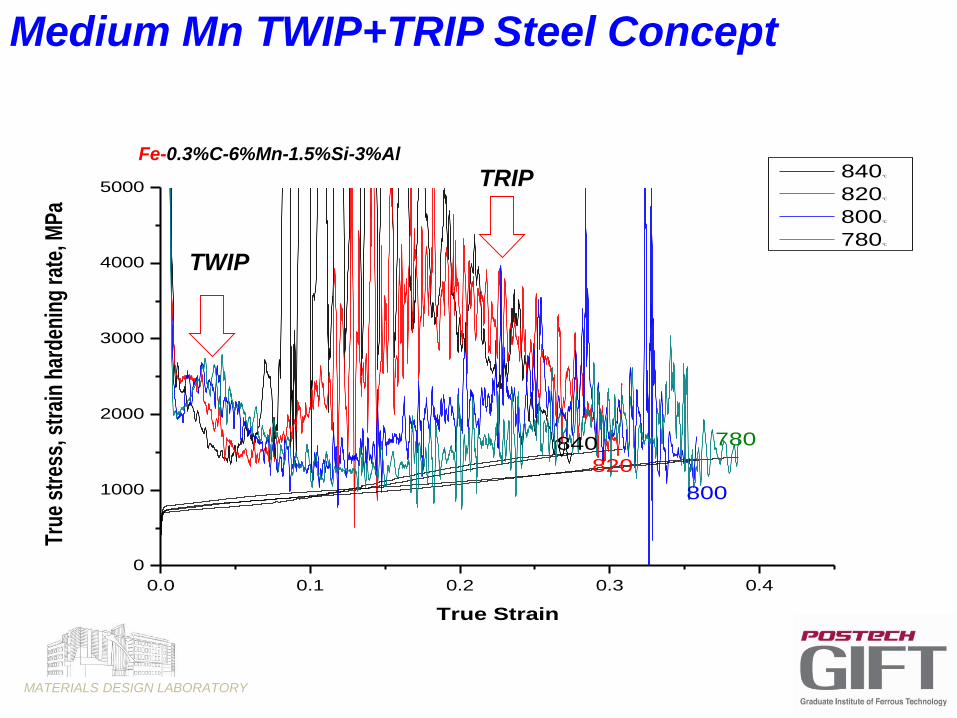
0.0 0.1 0.2 0.3 0.4
0
1000
2000
3000
4000
5000
780
800
840
True
str
ess,
str
ain
hard
enin
g ra
te, M
Pa
True Strain
840℃
820℃
800℃
780℃
820
TWIP
TRIPFe-0.3%C-6%Mn-1.5%Si-3%Al
Medium Mn TWIP+TRIP Steel Concept
MATERIALS DESIGN LABORATORY
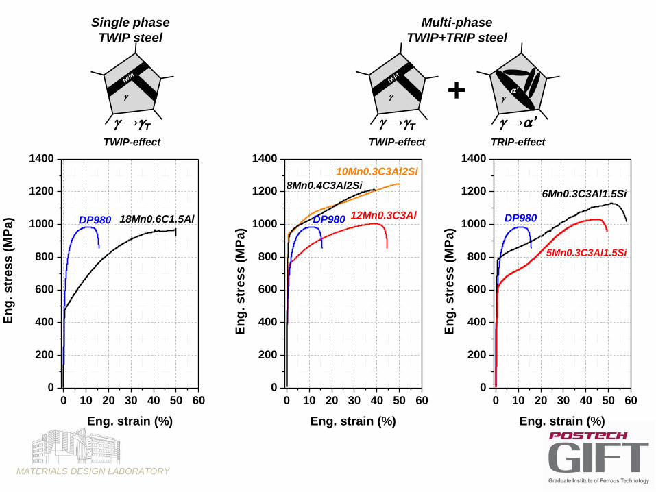
0 10 20 30 40 50 600
200
400
600
800
1000
1200
1400
0 10 20 30 40 50 600
200
400
600
800
1000
1200
1400
0 10 20 30 40 50 600
200
400
600
800
1000
1200
1400
8Mn0.4C3Al2Si
12Mn0.3C3Al18Mn0.6C1.5Al
En
g.
str
ess (
MP
a)
Eng. strain (%)
DP980 DP980
10Mn0.3C3Al2Si
En
g.
str
ess (
MP
a)
Eng. strain (%)
En
g.
str
ess (
MP
a)
Eng. strain (%)
DP980
6Mn0.3C3Al1.5Si
Single phase
TWIP steel
→T
TWIP-effect
→T
TWIP-effect
→’
TRIP-effect
’+
Multi-phase
TWIP+TRIP steel
5Mn0.3C3Al1.5Si

MATERIALS DESIGN LABORATORY
Conclusions
An UFG intercritically-annealed UHSS (UTS>1GPa) medium Mn steel grades for
automotive applications are being developed.
The material does not deform by localized Lüders band propagation, a common
problem for UFG materials.
The steel is designed to have two plasticity-enhancing mechanisms, the TWIP and
TRIP effects, being activate in succession in the austenite.
The alloy is designed to be compatible with current processing of CR strip for
automotive applications in CA and HDG lines. Concept is also compatible
with current requirements in terms of cost, processing, and application
performance.
Current research is focusing on:
- Zn and Zn-alloy coating
- Development of a hot rolled variant
- Further reduction of the alloy content
- Further increase in strength and ductility
MATERIALS DESIGN LABORATORY
Thank you
The support of the POSCO Technical Research Laboratories is gratefully acknowledged.


![CHAPTER 14michaeldmann.net/mann14.pdfKL: Mechansims of muscle contraction and its energetics. In: Mountcastle VB [ed]: Medical Physiology. 13th ed, Vol. 1. St. Louis, C.V. Mosby, 1974)](https://img.pdfslide.net/doc/110x75/610cc24ccb6153593f77b486/chapter-kl-mechansims-of-muscle-contraction-and-its-energetics-in-mountcastle.jpg)