Embed Size (px)
Citation preview
IVG Installation andTroubleshooting Guide
80-JE026-1 B
January 2016
Omnitracs, LLC717 N. Harwood Street, Suite 1300Dallas, TX 75201
Copyright © 2015-2016 Omnitracs, LLC. All rights reserved.
Omnitracs is a trademark of Omnitracs, LLC. All other trademarks are the property of their respective owners.
Omnitracs endeavors to ensure that the information in this document is correct and fairly stated, but Omnitracs is not liable for any errors or omissions. Published information may not be up to date, and it is important to confirm current status with Omnitracs.
This technical data may be subject to U.S. and international export, re-export or transfer (export) laws. Diversion contrary to U.S. and international law is strictly prohibited.
80-JE026-1 BJanuary 2016

Installation Contents
1. Component Overview
2. Activation
3. Installation Planning
4. Display Interface Unit Installation
5. Power I/O Cable Connection
6. Optional Accessories
7. System Verification
8. Appendix Contents
80-JE026-1 Rev. B iiiMAY CONTAIN U.S. AND INTERNATIONAL EXPORT CONTROLLED INFORMATION

Installation Contents
iv 80-JE026-1 Rev. BMAY CONTAIN U.S. AND INTERNATIONAL EXPORT CONTROLLED INFORMATION
Important Safety Information
Safety Definitions
The following Caution and Warning definitions are intended to advise the driver when it is safe to use a display unit.
CAUTION indicates a potentially hazardous situation which, if not avoided, may result in minor or moderate injury. It may also be used to alert against unsafe practices.
WARNING indicates a potentially hazardous situation which, if not avoided, could result in death or serious injury.
Safety Advice
The following Safety Advice is provided for drivers, installers, and application developers who use and/or locate all types of display units.
If you are a Driver, do not use a display unit when the vehicle is in motion.
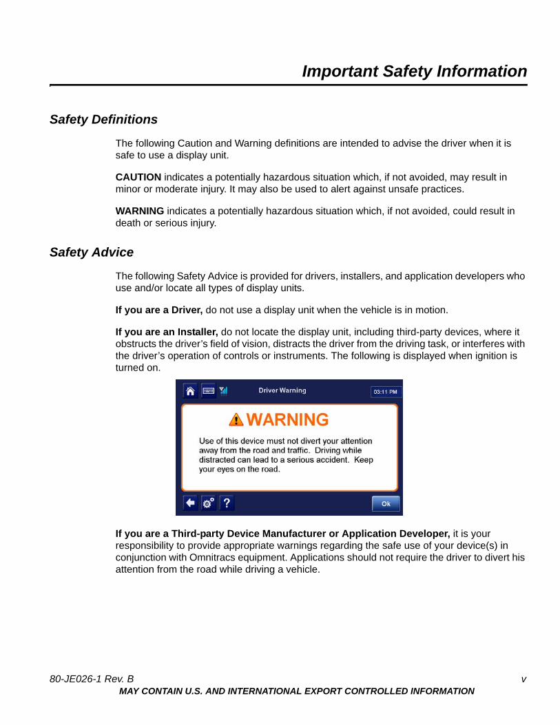
If you are an Installer, do not locate the display unit, including third-party devices, where it obstructs the driver’s field of vision, distracts the driver from the driving task, or interferes with the driver’s operation of controls or instruments. The following is displayed when ignition is turned on.
If you are a Third-party Device Manufacturer or Application Developer, it is your responsibility to provide appropriate warnings regarding the safe use of your device(s) in conjunction with Omnitracs equipment. Applications should not require the driver to divert his attention from the road while driving a vehicle.
80-JE026-1 Rev. B vMAY CONTAIN U.S. AND INTERNATIONAL EXPORT CONTROLLED INFORMATION
Safety Advice Important Safety Information
vi 80-JE026-1 Rev. BMAY CONTAIN U.S. AND INTERNATIONAL EXPORT CONTROLLED INFORMATION
1Component Overview
Components
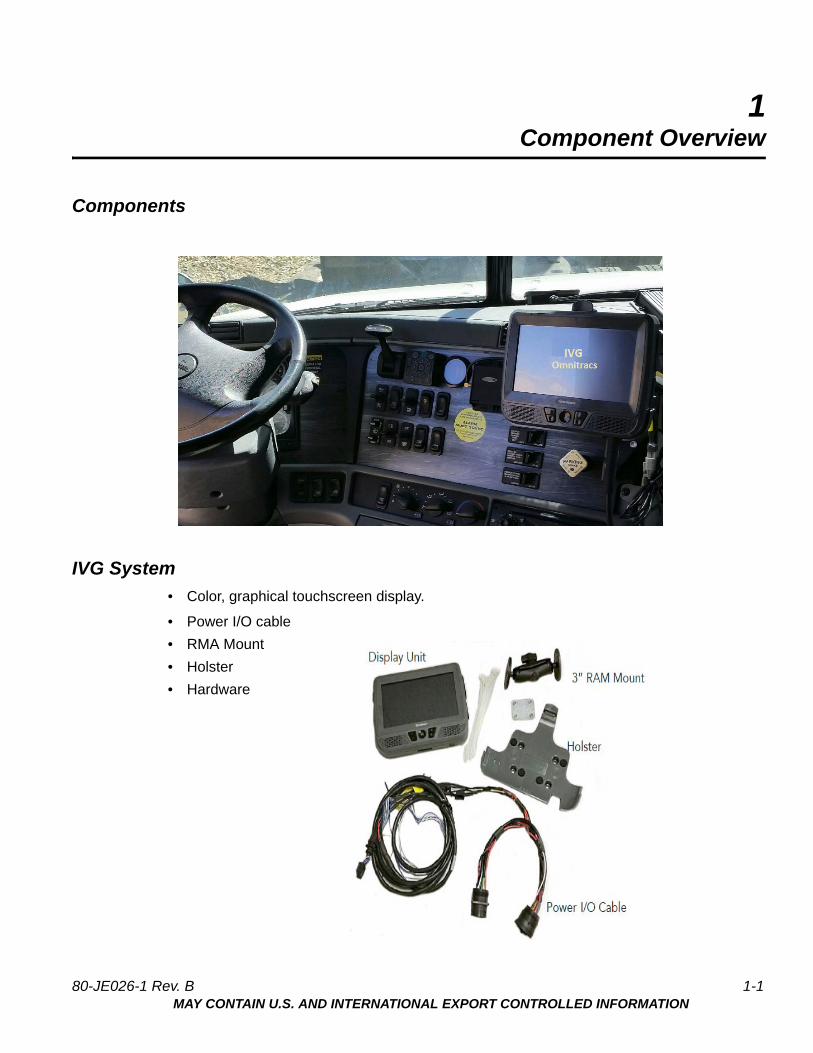
IVG System
• Color, graphical touchscreen display.
• Power I/O cable
• RMA Mount
• Holster
• Hardware
80-JE026-1 Rev. B 1-1MAY CONTAIN U.S. AND INTERNATIONAL EXPORT CONTROLLED INFORMATION
IVG Display Component Overview
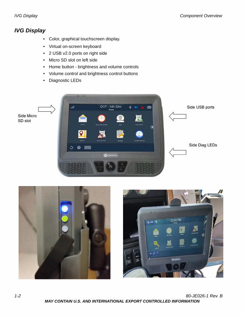
IVG Display
• Color, graphical touchscreen display.
• Virtual on-screen keyboard
• 2 USB v2.0 ports on right side
• Micro SD slot on left side
• Home button - brightness and volume controls
• Volume control and brightness control buttons
• Diagnostic LEDs
1-2 80-JE026-1 Rev. BMAY CONTAIN U.S. AND INTERNATIONAL EXPORT CONTROLLED INFORMATION
Component Overview Power I/O Cable (9-pin “Y” cable with standard flanged end)
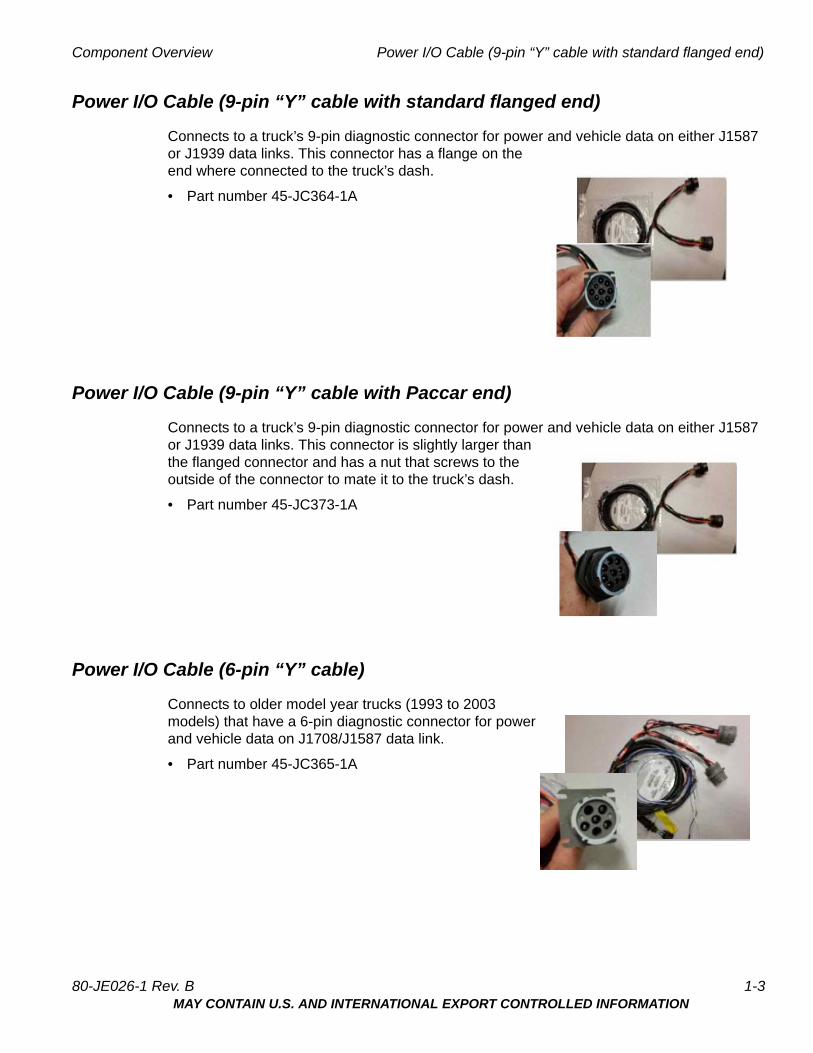
Power I/O Cable (9-pin “Y” cable with standard flanged end)
Connects to a truck’s 9-pin diagnostic connector for power and vehicle data on either J1587 or J1939 data links. This connector has a flange on theend where connected to the truck’s dash.
• Part number 45-JC364-1A
Power I/O Cable (9-pin “Y” cable with Paccar end)
Connects to a truck’s 9-pin diagnostic connector for power and vehicle data on either J1587 or J1939 data links. This connector is slightly larger thanthe flanged connector and has a nut that screws to theoutside of the connector to mate it to the truck’s dash.
• Part number 45-JC373-1A
Power I/O Cable (6-pin “Y” cable)
Connects to older model year trucks (1993 to 2003 models) that have a 6-pin diagnostic connector for powerand vehicle data on J1708/J1587 data link.
• Part number 45-JC365-1A
80-JE026-1 Rev. B 1-3MAY CONTAIN U.S. AND INTERNATIONAL EXPORT CONTROLLED INFORMATION
Volvo/Mack J1587/J1708 and J1939 Component Overview
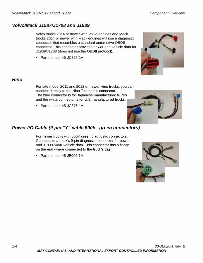
Volvo/Mack J1587/J1708 and J1939
Volvo trucks 2014 or newer with Volvo engines and Mack trucks 2014 or newer with Mack engines will use a diagnosticconnector that resembles a standard automotive OBDII connector. This connector provides power and vehicle data forJ1939/J1708 (does not use the OBDII protocol).
• Part number 45-JC366-1A
Hino
For late model 2011 and 2012 or newer Hino trucks, you canconnect directly to the Hino Telematics connector. The blue connector is for Japanese manufactured trucksand the white connector is for U.S.manufactured trucks.
• Part number 45-JC375-1A
Power I/O Cable (9-pin “Y” cable 500k - green connectors)
For newer trucks with 500K green diagnostic connectors.Connects to a truck’s 9-pin diagnostic connector for powerand J1939 500K vehicle data. This connector has a flangeon the end where connected to the truck’s dash.
• Part number 45-JE006-1A
1-4 80-JE026-1 Rev. BMAY CONTAIN U.S. AND INTERNATIONAL EXPORT CONTROLLED INFORMATION
Component Overview Display Holster
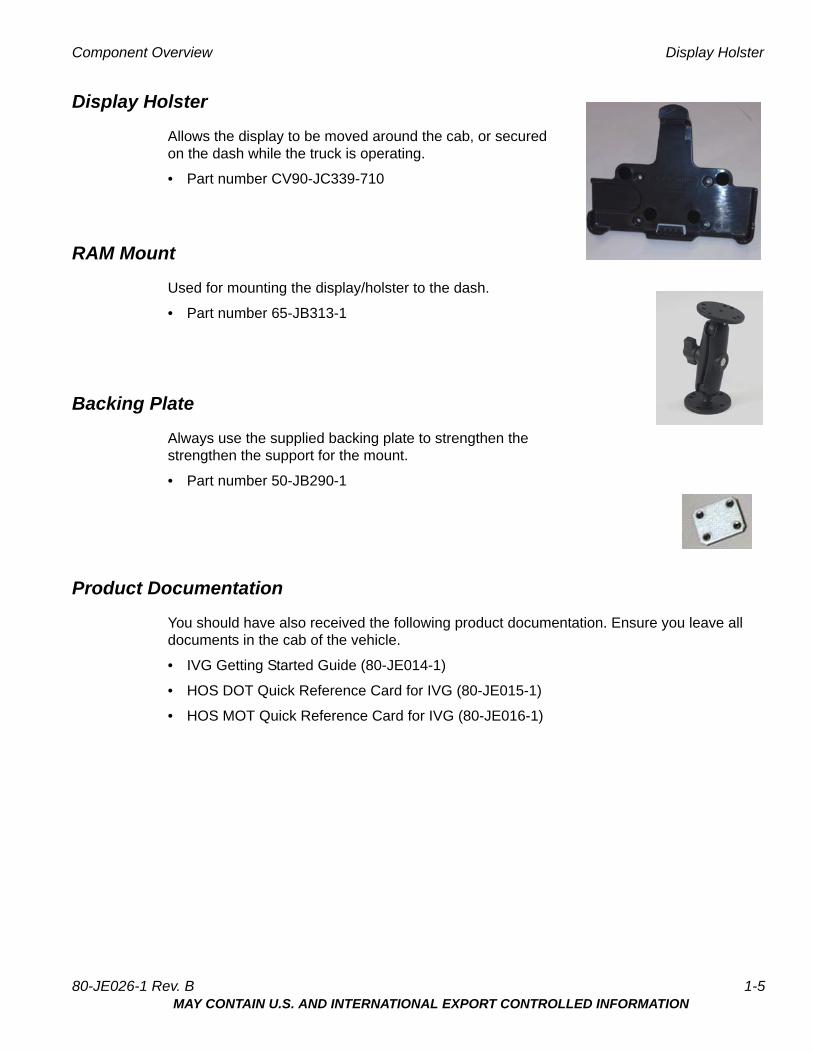
Display Holster
Allows the display to be moved around the cab, or secured on the dash while the truck is operating.
• Part number CV90-JC339-710
RAM Mount
Used for mounting the display/holster to the dash.
• Part number 65-JB313-1
Backing Plate
Always use the supplied backing plate to strengthen the strengthen the support for the mount.
• Part number 50-JB290-1
Product Documentation
You should have also received the following product documentation. Ensure you leave all documents in the cab of the vehicle.
• IVG Getting Started Guide (80-JE014-1)
• HOS DOT Quick Reference Card for IVG (80-JE015-1)
• HOS MOT Quick Reference Card for IVG (80-JE016-1)
80-JE026-1 Rev. B 1-5MAY CONTAIN U.S. AND INTERNATIONAL EXPORT CONTROLLED INFORMATION

Product Documentation Component Overview
1-6 80-JE026-1 Rev. BMAY CONTAIN U.S. AND INTERNATIONAL EXPORT CONTROLLED INFORMATION
2Activation
Activation
Online Activation
Online activation process should have already been completed at least one day prior to installation. This assigns the unit to the correct customer account and registers it on the cellular network.
IVG activation requires access to the Customer Portal. Contractors and Service Centers must work with the customers to activate units.
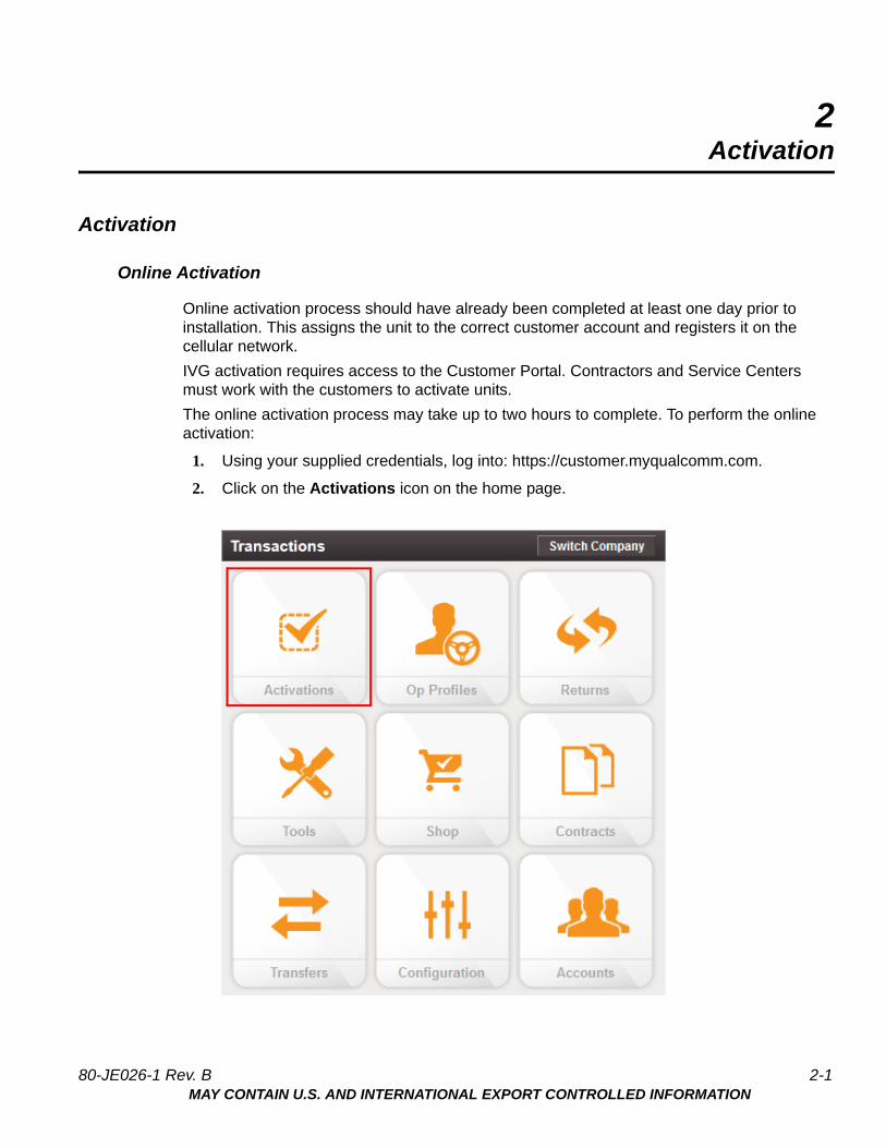
The online activation process may take up to two hours to complete. To perform the online activation:
1. Using your supplied credentials, log into: https://customer.myqualcomm.com.
2. Click on the Activations icon on the home page.
80-JE026-1 Rev. B 2-1MAY CONTAIN U.S. AND INTERNATIONAL EXPORT CONTROLLED INFORMATION

Online Activation Activation
You will then see the main Activations screen. From here click Continue under System Activation.
2-2 80-JE026-1 Rev. BMAY CONTAIN U.S. AND INTERNATIONAL EXPORT CONTROLLED INFORMATION
Activation Application Management
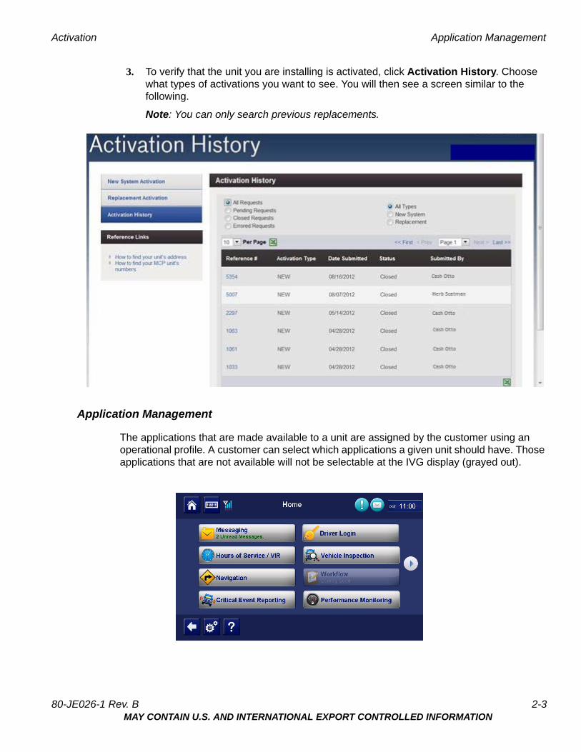
3. To verify that the unit you are installing is activated, click Activation History. Choose what types of activations you want to see. You will then see a screen similar to the following.
Note: You can only search previous replacements.
Application Management
The applications that are made available to a unit are assigned by the customer using an operational profile. A customer can select which applications a given unit should have. Those applications that are not available will not be selectable at the IVG display (grayed out).
80-JE026-1 Rev. B 2-3MAY CONTAIN U.S. AND INTERNATIONAL EXPORT CONTROLLED INFORMATION
Application Management Activation
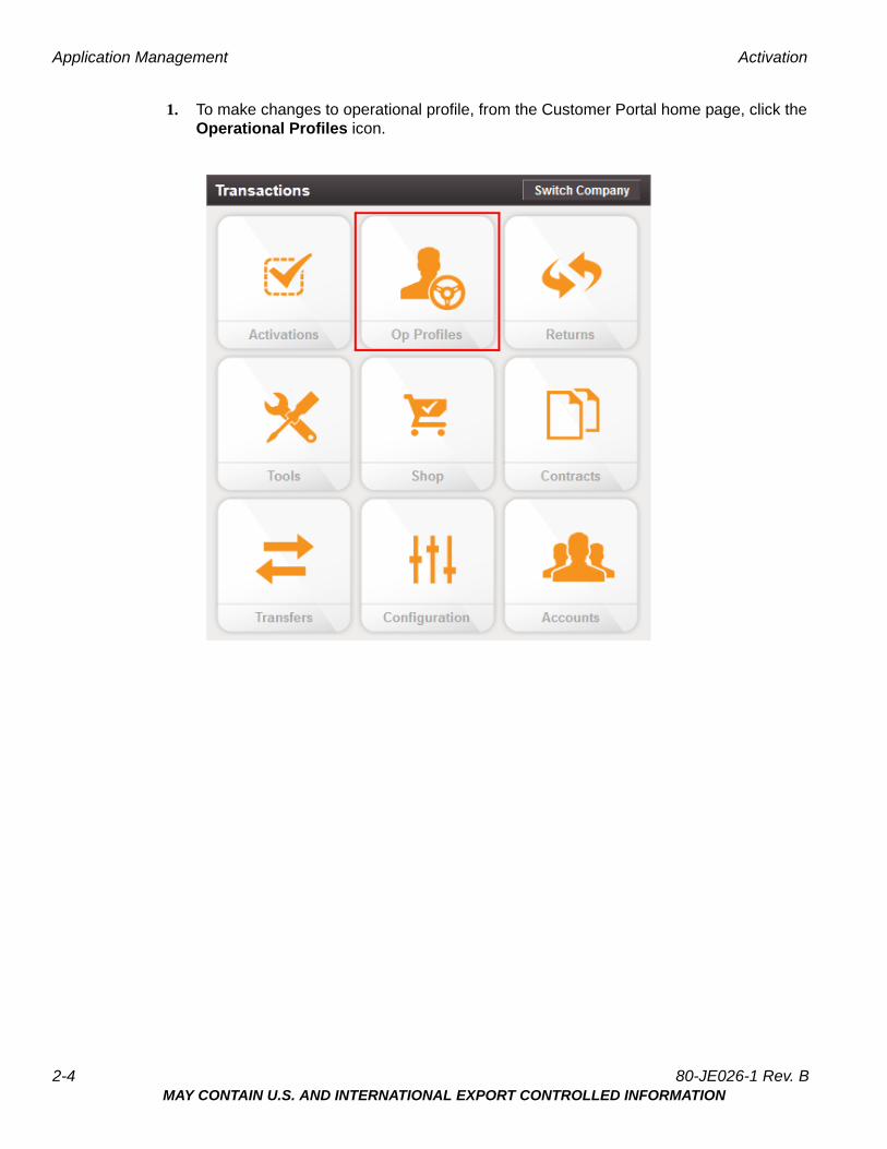
1. To make changes to operational profile, from the Customer Portal home page, click the Operational Profiles icon.
2-4 80-JE026-1 Rev. BMAY CONTAIN U.S. AND INTERNATIONAL EXPORT CONTROLLED INFORMATION
Activation Application Management
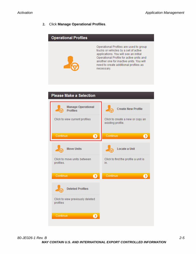
2. Click Manage Operational Profiles.
80-JE026-1 Rev. B 2-5MAY CONTAIN U.S. AND INTERNATIONAL EXPORT CONTROLLED INFORMATION

Application Management Activation
3. A screen similar to the below will list the available operational profiles.
2-6 80-JE026-1 Rev. BMAY CONTAIN U.S. AND INTERNATIONAL EXPORT CONTROLLED INFORMATION
3Installation Planning
Regulatory Compliance Information
FCC/IC Compliance Statement
This device complies with part 15 of the FCC Rules. Operation is subject to the following two conditions:
(1) This device may not cause harmful interference, and
(2) this device must accept any interference received, including interference that may cause undesired operation.
Note
This equipment has been tested and found to comply with the limits for a Class A digital device, pursuant to part 15 of the FCC Rules. These limits are designed to provide reasonable protection against harmful interference when the equipment is operated in a commercial environment. This equipment generates, uses, and can radiate radio frequency energy and, if not installed and used in accordance with the instruction manual, may cause harmful interference to radio communications. Operation of this equipment in a residential area may cause harmful interference in which case the user will be required to correct the interference at his own expense.
Caution
Any changes or modifications not expressly approved by the party responsible for compliance to this equipment would void the user's authority to operate this device.
This device complies with Industry Canada's license-exempt RSSs. Operation is subject to the following two conditions:
(1) This device may not cause interference; and
(2) This device must accept any interference, including interference that may cause undesired operation of the device.
Le présent appareil est conforme aux CNR d'Industrie Canada applicables aux appareils radio exempts de licence. L'exploitation est autorisée aux deux conditions suivantes :
1) l'appareil ne doit pas produire de brouillage;
2) l'utilisateur de l'appareil doit accepter tout brouillage radioélectrique subi, même si le brouillage est susceptible d'en compromettre le fonctionnement.
80-JE026-1 Rev. B 3-1MAY CONTAIN U.S. AND INTERNATIONAL EXPORT CONTROLLED INFORMATION
RF Exposure Information (SAR) Installation Planning
CAN ICES-3 (A)/NMB-3(A)
RF Exposure Information (SAR)
Refer to Appendix I, RF Exposure Information (SAR)
Installation Guidelines
Typical Installation Steps
1. Online Activation (at least one day prior)
2. Display Installation
3. Power/IO and ignition connection
4. System verification
Safety, Reliability, and Accessibility
• Use eye protection when using a drill/performing work that may be hazardous to the eyes.
• Use ear protection in noisy work areas.
• Wear appropriate clothing/uniforms and safety shoes.
• Maintain three points of contact when climbing in and out of cab.
• Make sure you know what is behind the area before you drill.
• Install equipment so it will not cause damage to the vehicle or work loose over time.
• Make sure there are no loose components/cables and no unsecured components.
• Use solid mounting surfaces.
• Route all cables away from hot or abrasive areas.
• Choose installation locations where components can be easily serviced.
• Choose installation locations where components are safe from tampering and damage.
Tools and Supplies Recommended for Installation
• Crimpers
• Diagonal Wire Cutters
• Wire Strippers
• Screwdrivers: Phillips #2 and Slotted
• Torx Drivers: #20 and #25
• Volt/ohm Meter
• Flush Cutters
• Flash/Drop Light
3-2 80-JE026-1 Rev. BMAY CONTAIN U.S. AND INTERNATIONAL EXPORT CONTROLLED INFORMATION

4Display Interface Unit Installation
Selecting a Mounting Location
IMPORTANT SAFETY INFORMATION
WARNING
Do not locate the display unit where it obstructs the driver’s field of vision, distracts the driver from the driving task, interferes with the driver’s operation of controls or
displays, or creates a safety hazard. Follow all laws and regulations governing the placement of equipment and mounts.
DO locate the Display where:
• it can be safely installed on a secured bracket that is robust enough to minimize any vibration and sustain the weight of the Display.
• the mounting surface is strong enough to support the mounting hardware.
• the mounting surface is flat.
• it is in the driver’s line-of-sight, easy to touch, but does not block the view of the road or mirrors.
• the surrounding area is clear of dash controls and gauges.
• it is not mounted in constant, direct sunlight.
• it does not limit a passenger’s leg room or block access to any other compartments.
• it does not interfere with anyone entering or exiting the vehicle cab.
• it is not likely to impact the driver or passenger in case of an accident or collision.
80-JE026-1 Rev. B 4-1MAY CONTAIN U.S. AND INTERNATIONAL EXPORT CONTROLLED INFORMATION
Installing the Display Display Interface Unit Installation
DO NOT locate the display where it:
• obstructs the driver’s field of vision.
• distracts the driver from the driving task.
• interferes with the driver’s operation of controls or shifting.
• obstructs the area swept by the windshield wipers.
• blocks the deployment of an airbag.
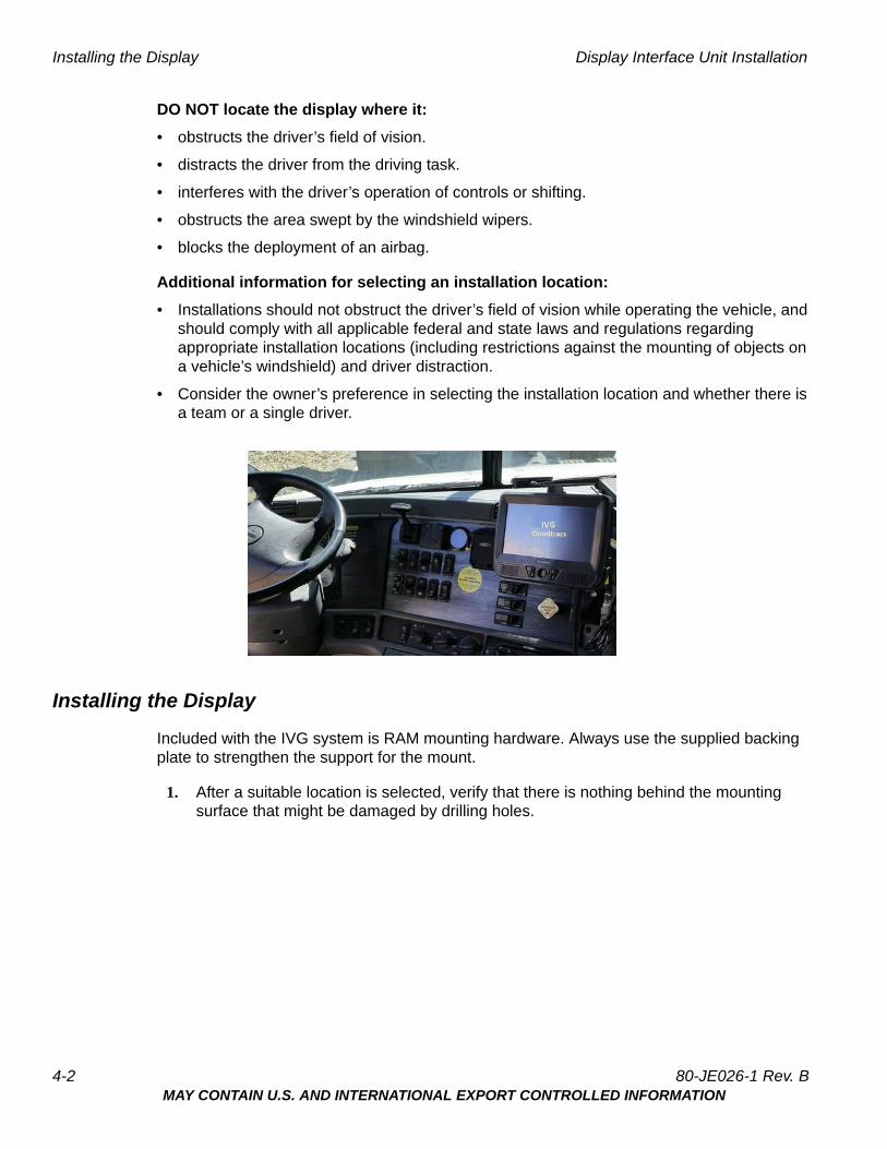
Additional information for selecting an installation location:
• Installations should not obstruct the driver’s field of vision while operating the vehicle, and should comply with all applicable federal and state laws and regulations regarding appropriate installation locations (including restrictions against the mounting of objects on a vehicle’s windshield) and driver distraction.
• Consider the owner’s preference in selecting the installation location and whether there is a team or a single driver.
Installing the Display
Included with the IVG system is RAM mounting hardware. Always use the supplied backing plate to strengthen the support for the mount.
1. After a suitable location is selected, verify that there is nothing behind the mounting surface that might be damaged by drilling holes.
4-2 80-JE026-1 Rev. BMAY CONTAIN U.S. AND INTERNATIONAL EXPORT CONTROLLED INFORMATION
Display Interface Unit Installation Installing the Display
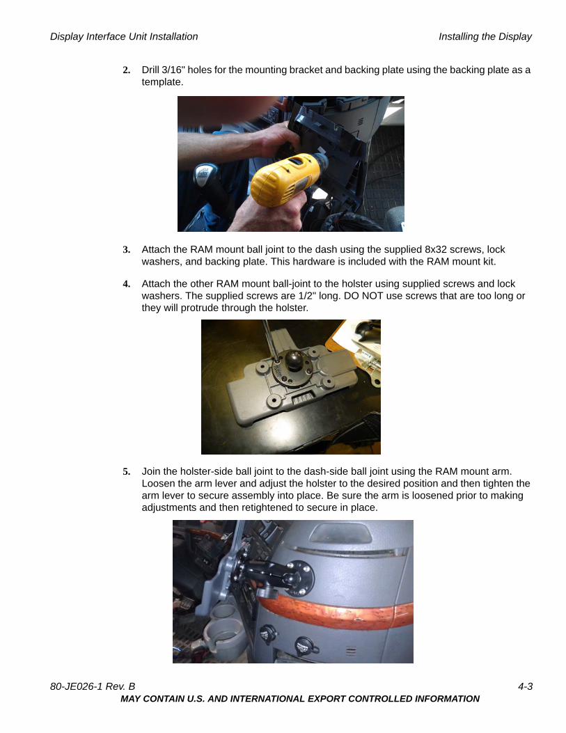
2. Drill 3/16" holes for the mounting bracket and backing plate using the backing plate as a template.
3. Attach the RAM mount ball joint to the dash using the supplied 8x32 screws, lock washers, and backing plate. This hardware is included with the RAM mount kit.
4. Attach the other RAM mount ball-joint to the holster using supplied screws and lock washers. The supplied screws are 1/2" long. DO NOT use screws that are too long or they will protrude through the holster.
5. Join the holster-side ball joint to the dash-side ball joint using the RAM mount arm. Loosen the arm lever and adjust the holster to the desired position and then tighten the arm lever to secure assembly into place. Be sure the arm is loosened prior to making adjustments and then retightened to secure in place.
80-JE026-1 Rev. B 4-3MAY CONTAIN U.S. AND INTERNATIONAL EXPORT CONTROLLED INFORMATION

Installing the Display Display Interface Unit Installation
6. Snap the display into the holster by placing the bottom into the lower holster tabs and then push the top into the upper holster tab. It will snap into place.
7. Allow just enough display cable slack so the DIU can reach the driver steering wheel only. Ensure any excess cable is secured and does not interfere with the operation of the vehicle. Cable should not drape on the floor or cause a tripping hazard.
8. Add a tiewrap strain relief to the DIU cable where it comes out from under or behind the dash so it can’t be pulled out further.
WARNING
Excess cable can be a tripping hazard. Ensure cable is not draped where it will interfere with either the driver or passenger as they move within the cab.
4-4 80-JE026-1 Rev. BMAY CONTAIN U.S. AND INTERNATIONAL EXPORT CONTROLLED INFORMATION

5Power I/O Cable Connection
The power I/O cable is used to connect to a truck’s Diagnostic Connector. It provides both power and the necessary vehicle data for the IVG system. There are multiple masterpacks depending on the truck type. See the individual Truck Installation Suggestion documents for more information. See Appendix G: Component Information for more information
Cable Trucks
9-pin Most 2006 and newer trucks
6-pin Most 2005 and older trucks
9-pin adapter Late model Kenworth and Peterbilt trucks
OBDII style 2014 and newer Volvo/Mack trucks
80-JE026-1 Rev. B 5-1MAY CONTAIN U.S. AND INTERNATIONAL EXPORT CONTROLLED INFORMATION

Connecting the Power I/O Cable Power I/O Cable Connection
The appropriate IVG kit/masterpack should have been ordered for your installation. If the power I/O Cable connector does not mate to the truck’s diagnostic connector, the Y portion of the power I/O Cable will need to be cut off and wires will need to be crimp spliced. See Chapter C: General Wiring and Installation Guidelines for instructions.
Connecting the Power I/O Cable
1. With the truck’s ignition OFF, remove and push back existing truck diagnostic connector. Check connector to verify it’s clean of debris and there are no bent pins.
2. Connect the power I/O cable connector to the truck’s diagnostic connector. Verify the outer ring is twisted and clicks into place so the ends do not become unconnected by accident. Verify by pull testing the connector.
3. Put the unused power I/O cable end where the truck’s diagnostic connector was located.
4. Route power cable to the IVG display location..
5. Remove torx10 screws from door panel on back side of IVG display and connect power cable to the IVG display. Ensure it latches solidly.
6. Replace door panel and secure any excess cable using tie-wraps.
9-pin 500 Kbps 2016 and newer model trucks with green diagnostic connectors
Hino Late 2011 and newer Hino trucks
5-2 80-JE026-1 Rev. BMAY CONTAIN U.S. AND INTERNATIONAL EXPORT CONTROLLED INFORMATION
6Optional Accessories
Optional connections:
• PTO (Power Take-off)
• Trailer Tracks
• Panic Button
PTO (Power Take-off) Overview—Optional Connection
This option provides the ability to log the time the vehicle engine is used for operational idle purposes, such as when it is powering auxiliary devices using a pump or compressor.
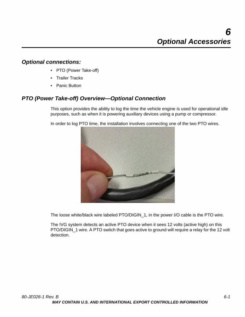
In order to log PTO time, the installation involves connecting one of the two PTO wires.
The loose white/black wire labeled PTO/DIGIN_1, in the power I/O cable is the PTO wire.
The IVG system detects an active PTO device when it sees 12 volts (active high) on this PTO/DIGIN_1 wire. A PTO switch that goes active to ground will require a relay for the 12 volt detection.
80-JE026-1 Rev. B 6-1MAY CONTAIN U.S. AND INTERNATIONAL EXPORT CONTROLLED INFORMATION
PTO Installation Optional Accessories
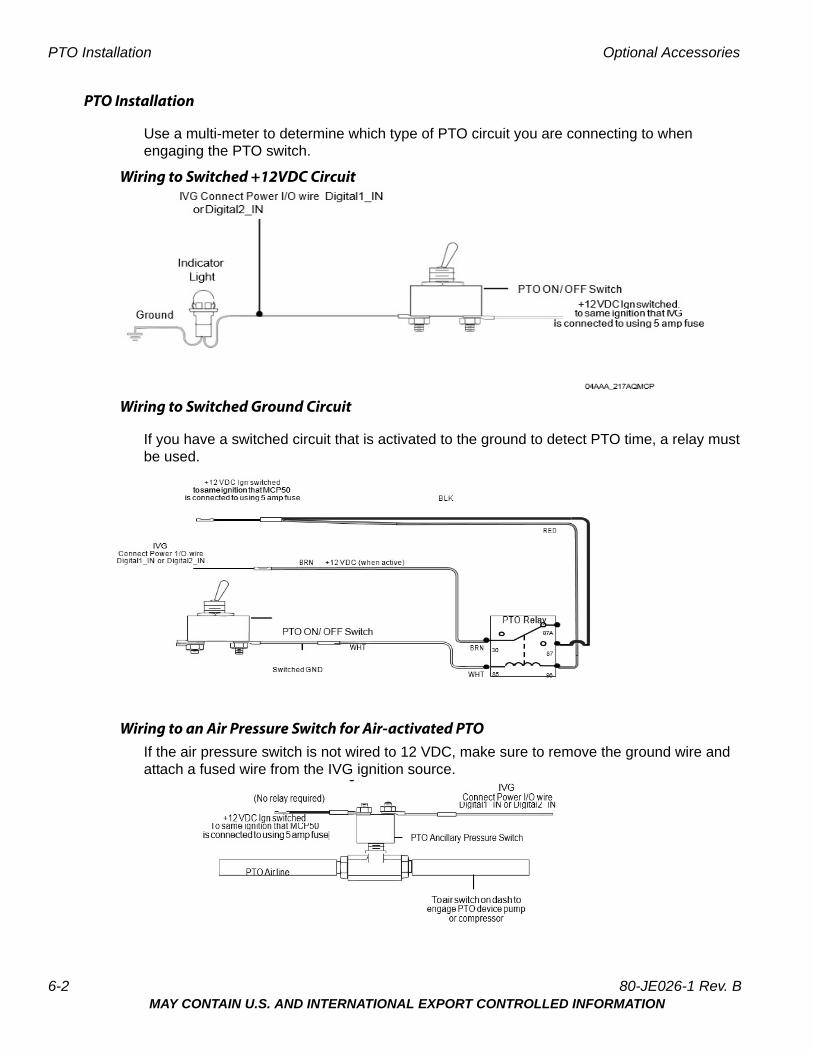
PTO Installation
Use a multi-meter to determine which type of PTO circuit you are connecting to when engaging the PTO switch.
Wiring to Switched +12VDC Circuit
Wiring to Switched Ground Circuit
If you have a switched circuit that is activated to the ground to detect PTO time, a relay must be used.
Wiring to an Air Pressure Switch for Air-activated PTOIf the air pressure switch is not wired to 12 VDC, make sure to remove the ground wire and attach a fused wire from the IVG ignition source.
6-2 80-JE026-1 Rev. BMAY CONTAIN U.S. AND INTERNATIONAL EXPORT CONTROLLED INFORMATION

Optional Accessories PTO Data Input Verification Procedure
PTO Data Input Verification Procedure
1. Start the vehicle.
2. Turn the PTO switch ON.
3. Navigate to the System VDS screen.
4. Tap the green up and down arrow button at bottom of the screen (circled below).
5. Verify the PTOC has a green dot under the Index column and shows “On” under the State column.
NOTE:
PTOC: PTO/DIGIN_1 in wire in the wire harnessIf PTOC is not showing a green dot or "On," check the PTO wire connections.
6. Turn off PTO device. The green dot and state will change (i.e., to a black dot and “Off”).
7. At this point, the PTO wire installation verification is complete.
8. Verify through the Performance Monitoring screens that the PTO application is recording correctly.
80-JE026-1 Rev. B 6-3MAY CONTAIN U.S. AND INTERNATIONAL EXPORT CONTROLLED INFORMATION
Trailer Tracks Installation (placeholder) Optional Accessories
9. Start the vehicle.
10. Turn the PTO device to ON.
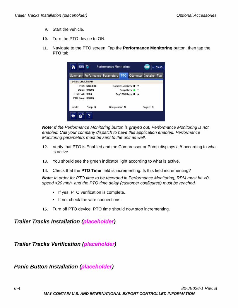
11. Navigate to the PTO screen. Tap the Performance Monitoring button, then tap the PTO tab.
Note: If the Performance Monitoring button is grayed out, Performance Monitoring is not enabled. Call your company dispatch to have this application enabled. Performance Monitoring parameters must be sent to the unit as well.
12. Verify that PTO is Enabled and the Compressor or Pump displays a Y according to what is active.
13. You should see the green indicator light according to what is active.
14. Check that the PTO Time field is incrementing. Is this field incrementing?
Note: In order for PTO time to be recorded in Performance Monitoring, RPM must be >0, speed <20 mph, and the PTO time delay (customer configured) must be reached.
• If yes, PTO verification is complete.
• If no, check the wire connections.
15. Turn off PTO device. PTO time should now stop incrementing.
Trailer Tracks Installation (placeholder)
Trailer Tracks Verification (placeholder)
Panic Button Installation (placeholder)
6-4 80-JE026-1 Rev. BMAY CONTAIN U.S. AND INTERNATIONAL EXPORT CONTROLLED INFORMATION
Optional Accessories Panic Button Verification (placeholder)
Panic Button Verification (placeholder)
80-JE026-1 Rev. B 6-5MAY CONTAIN U.S. AND INTERNATIONAL EXPORT CONTROLLED INFORMATION
Panic Button Verification (placeholder) Optional Accessories
6-6 80-JE026-1 Rev. BMAY CONTAIN U.S. AND INTERNATIONAL EXPORT CONTROLLED INFORMATION

7System Verification
Performing System Verification
Shortly after you power up the IVG, the Driver Warning screen appears. After tapping the OK button, the IVG Home screen displays.
1. Tap the arrow on the right until you see the System button, then tap the System button.
2. Tap the Diag tab. Note: the IVG Unit Address (UA) shows at the top.
3. Tap the Run All button, located at the bottom right of the screen. The system runs tests on all listed items then displays the results.
80-JE026-1 Rev. B 7-1MAY CONTAIN U.S. AND INTERNATIONAL EXPORT CONTROLLED INFORMATION

Performing System Verification System Verification
If the test passes, a (green ) is shown. If the test fails, a (red X) is shown.
Note: Green checkmarks next to Cellular Signal Strength, Cellular End to End, GPS, and Core Data Items are required for the IVG system to be ready for use.
Item Description
Cellular Signal Strength Will show a green checkmark when in good cellular network coverage. See Chapter 13: Cellular Signal Strength Problems if red X.
Cellular End To End Will show a green checkmark if the unit is successfully transmitting with Omnitracs and received an acknowledgement back. See Chapter 12: Cellular End to End Problems if red X.
GPS fix test Will show a green checkmark if GPS network is detected and it is getting a 3D fix. See Chapter 15: GPS Fix Problem if red X.
Core Data Items Will show a green checkmark if Speed, RPM, Distance LTD, and Fuel LTD is being detected. See Chapter 19: Core Data Problem if red X.
CDD Database Sync Will show a green checkmark when database has been synchronized with NOC (usually take 5 to 10 minutes after unit is first powered up. See Chapter 14: CDD Database Sync Problem if red X.
Ignition On Will show a green checkmark if the ignition is ON. See Chapter 18: Ignition On Detection Problem if red X.
First page of tests
7-2 80-JE026-1 Rev. BMAY CONTAIN U.S. AND INTERNATIONAL EXPORT CONTROLLED INFORMATION
System Verification Performing System Verification
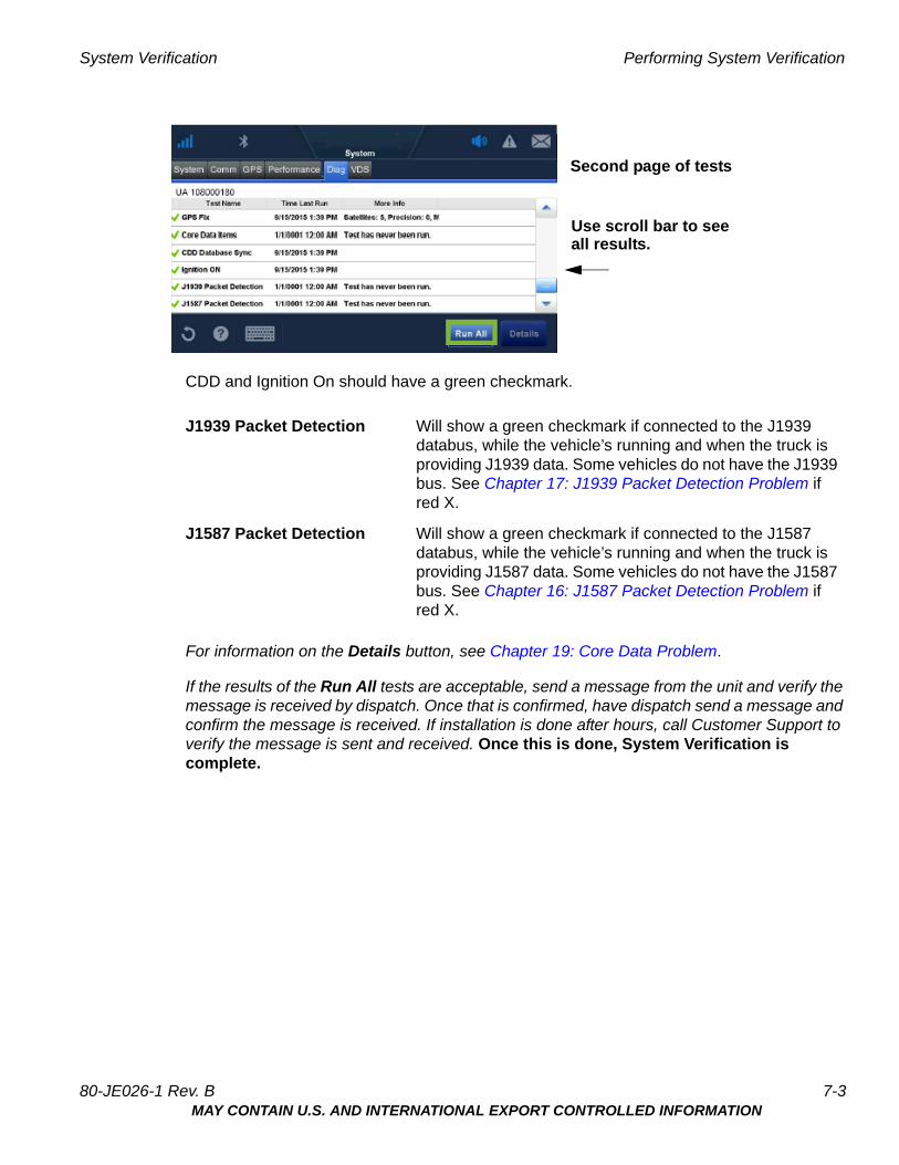
CDD and Ignition On should have a green checkmark.
For information on the Details button, see Chapter 19: Core Data Problem.
If the results of the Run All tests are acceptable, send a message from the unit and verify the message is received by dispatch. Once that is confirmed, have dispatch send a message and confirm the message is received. If installation is done after hours, call Customer Support to verify the message is sent and received. Once this is done, System Verification is complete.
J1939 Packet Detection Will show a green checkmark if connected to the J1939 databus, while the vehicle’s running and when the truck is providing J1939 data. Some vehicles do not have the J1939 bus. See Chapter 17: J1939 Packet Detection Problem if red X.
J1587 Packet Detection Will show a green checkmark if connected to the J1587 databus, while the vehicle’s running and when the truck is providing J1587 data. Some vehicles do not have the J1587 bus. See Chapter 16: J1587 Packet Detection Problem if red X.
Use scroll bar to seeall results.
Second page of tests
80-JE026-1 Rev. B 7-3MAY CONTAIN U.S. AND INTERNATIONAL EXPORT CONTROLLED INFORMATION

Performing System Verification System Verification
7-4 80-JE026-1 Rev. BMAY CONTAIN U.S. AND INTERNATIONAL EXPORT CONTROLLED INFORMATION
Troubleshooting Contents
8. Troubleshooting Best Practices
9. Display Screen is Dark or Blank
10. Display Problems
11. Cannot Send Messages
12. Cellular End to End Problems
13. Cellular Signal Strength Problems
14. CDD Database Sync Problem
15. GPS Fix Problem
16. J1587 Packet Detection Problem
17. J1939 Packet Detection Problem
18. Ignition On Detection Problem
19. Core Data Problem
20. IVG DIU LED Indicator
21. IVG Display Icons and Indicators
22.Performance Monitoring Troubleshooting
23. Critical Event Reporting Troubleshooting
24. Optional Accessories Troubleshooting
80-JE026-1 Rev. BMAY CONTAIN U.S. AND INTERNATIONAL EXPORT CONTROLLED INFORMATION

Troubleshooting Contents
80-JE026-1 Rev. BMAY CONTAIN U.S. AND INTERNATIONAL EXPORT CONTROLLED INFORMATION
8Troubleshooting Best Practices
Troubleshooting Guidelines
Keep Known Good IVG Component Spares in Shop
Spare parts should include:
• IVG system
• IVG power I/O cable
Use a Test Cart to Perform Bad Part Verification/Double Checking
If an Omnitracs IVG part is diagnosed bad on a truck, insert the failed part on the test cart or another truck that is known to be good (diagnostic connector).
• If part continues to fail, part should be RMAd or replaced in the event it’s the power I/O cable.
• If the suspect part does not fail on the test cart, further troubleshooting will be necessary.
Perform a Visual Inspection of the Installed IVG
• Check for damaged cables, improper electrical connections, loose connections, and the integrity of the installation.
• Bad mounts can contribute to system problems.
• Loose connections or parts not installed properly can allow excessive vibration which can affect system performance.
Reseat Cable
• Always inspect and reseat the cable connector prior to replacing the IVG display.
• Inspect for corrosion and bent, broken, pushed, missing pins, and/or sockets.
Verify IVG Display LED Indicator are in a Normal State
• When booting up, several of the LEDs will blink.
• Once boot up is completed, the top LED will blink blue every 1-2 seconds when operating normally. The middle LED will blink green every 3-4 seconds.
80-JE026-1 Rev. B 8-1MAY CONTAIN U.S. AND INTERNATIONAL EXPORT CONTROLLED INFORMATION
Check System Voltage Measurements and Grounding Troubleshooting Best Practices
Check System Voltage Measurements and Grounding
• Use the same ground reference that the particular circuit uses.
• Verify that vehicle battery and cables are in good condition.
• Check voltages (see Appendix A for more information):
Replace Only Faulty Parts
Typically, only one part is bad. Once the system is operating, you can substitute suspect parts back into the system to verify which part is bad, or use a test cart equipped with known good spare parts to retest suspect parts.
Determine If the Problem Is Intermittent
Check for bad or loose electrical connections including cable connectors, ring terminals, butt splices, and power/ground connections. These can contribute to intermittent system performance.
8-2 80-JE026-1 Rev. BMAY CONTAIN U.S. AND INTERNATIONAL EXPORT CONTROLLED INFORMATION
9Display Screen is Dark or Blank
Problem: Display Screen is Dark or Blank
If the display is blank or dark it could be:
• Unit is asleep (i.e. ignition detected as OFF and power down timer exceeded)
• Power source or power I/O cable problem
• Ignition detection not working
• Faulty IVG Display
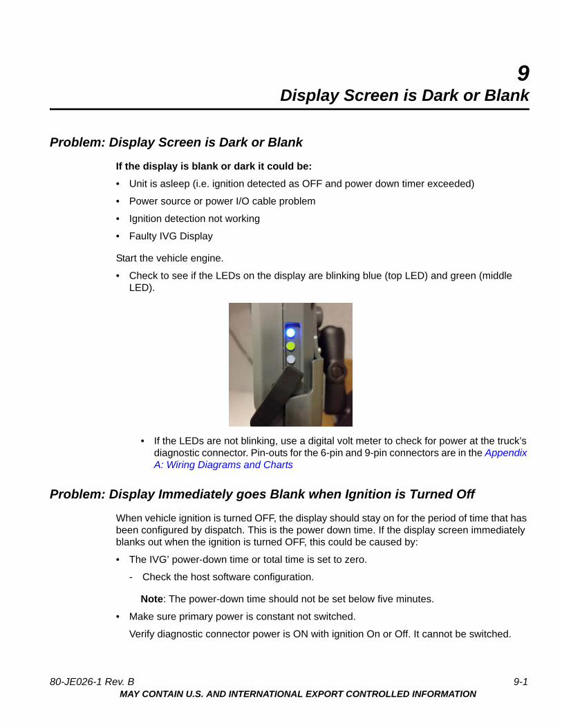
Start the vehicle engine.
• Check to see if the LEDs on the display are blinking blue (top LED) and green (middle LED).
• If the LEDs are not blinking, use a digital volt meter to check for power at the truck’s diagnostic connector. Pin-outs for the 6-pin and 9-pin connectors are in the Appendix A: Wiring Diagrams and Charts
Problem: Display Immediately goes Blank when Ignition is Turned Off
When vehicle ignition is turned OFF, the display should stay on for the period of time that has been configured by dispatch. This is the power down time. If the display screen immediately blanks out when the ignition is turned OFF, this could be caused by:
• The IVG’ power-down time or total time is set to zero.
- Check the host software configuration.
Note: The power-down time should not be set below five minutes.
• Make sure primary power is constant not switched.
Verify diagnostic connector power is ON with ignition On or Off. It cannot be switched.
80-JE026-1 Rev. B 9-1MAY CONTAIN U.S. AND INTERNATIONAL EXPORT CONTROLLED INFORMATION
Problem: Display Immediately goes Blank when Ignition is Turned Off Display Screen is Dark or Blank
See, Appendix A: Wiring Diagrams and Charts, for wire diagrams and schematics of the different diagnostic connectors.
9-2 80-JE026-1 Rev. BMAY CONTAIN U.S. AND INTERNATIONAL EXPORT CONTROLLED INFORMATION
10Display Problems
IVG Display Overview
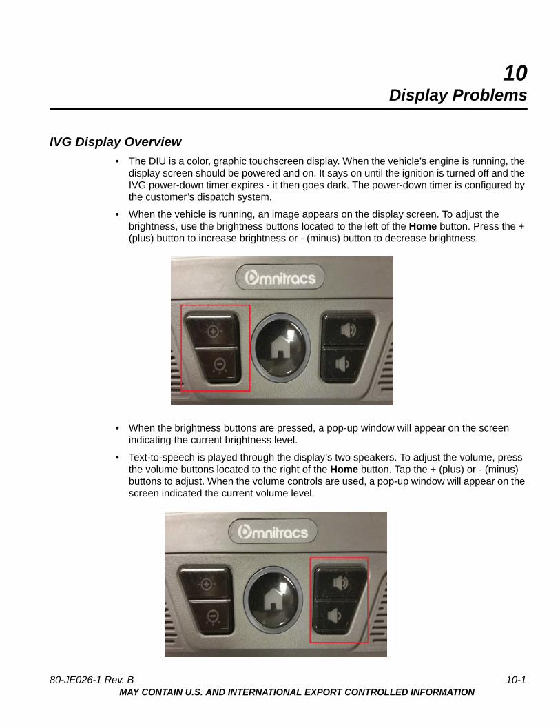
• The DIU is a color, graphic touchscreen display. When the vehicle’s engine is running, the display screen should be powered and on. It says on until the ignition is turned off and the IVG power-down timer expires - it then goes dark. The power-down timer is configured by the customer’s dispatch system.
• When the vehicle is running, an image appears on the display screen. To adjust the brightness, use the brightness buttons located to the left of the Home button. Press the + (plus) button to increase brightness or - (minus) button to decrease brightness.
• When the brightness buttons are pressed, a pop-up window will appear on the screen indicating the current brightness level.
• Text-to-speech is played through the display’s two speakers. To adjust the volume, press the volume buttons located to the right of the Home button. Tap the + (plus) or - (minus) buttons to adjust. When the volume controls are used, a pop-up window will appear on the screen indicated the current volume level.
80-JE026-1 Rev. B 10-1MAY CONTAIN U.S. AND INTERNATIONAL EXPORT CONTROLLED INFORMATION
Problem: Touchscreen Non-responsive/Calibration Display Problems
Problem: Touchscreen Non-responsive/Calibration
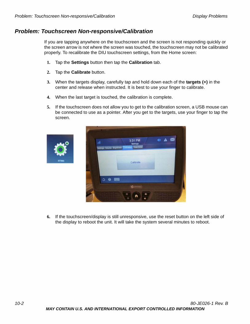
If you are tapping anywhere on the touchscreen and the screen is not responding quickly or the screen arrow is not where the screen was touched, the touchscreen may not be calibrated properly. To recalibrate the DIU touchscreen settings, from the Home screen:
1. Tap the Settings button then tap the Calibration tab.
2. Tap the Calibrate button.
3. When the targets display, carefully tap and hold down each of the targets (+) in the center and release when instructed. It is best to use your finger to calibrate.
4. When the last target is touched, the calibration is complete.
5. If the touchscreen does not allow you to get to the calibration screen, a USB mouse can be connected to use as a pointer. After you get to the targets, use your finger to tap the screen.
6. If the touchscreen/display is still unresponsive, use the reset button on the left side of the display to reboot the unit. It will take the system several minutes to reboot.
10-2 80-JE026-1 Rev. BMAY CONTAIN U.S. AND INTERNATIONAL EXPORT CONTROLLED INFORMATION
11Cannot Send Messages
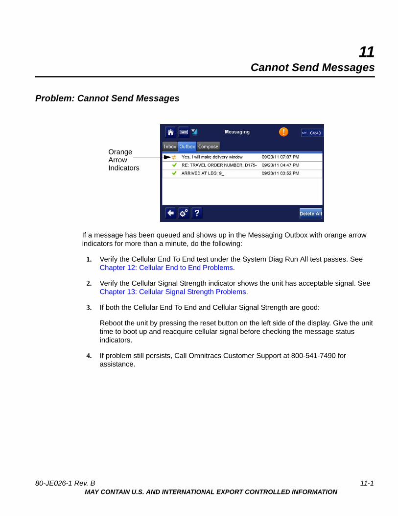
Problem: Cannot Send Messages
If a message has been queued and shows up in the Messaging Outbox with orange arrow indicators for more than a minute, do the following:
1. Verify the Cellular End To End test under the System Diag Run All test passes. See Chapter 12: Cellular End to End Problems.
2. Verify the Cellular Signal Strength indicator shows the unit has acceptable signal. See Chapter 13: Cellular Signal Strength Problems.
3. If both the Cellular End To End and Cellular Signal Strength are good:
Reboot the unit by pressing the reset button on the left side of the display. Give the unit time to boot up and reacquire cellular signal before checking the message status indicators.
4. If problem still persists, Call Omnitracs Customer Support at 800-541-7490 for assistance.
OrangeArrowIndicators
80-JE026-1 Rev. B 11-1MAY CONTAIN U.S. AND INTERNATIONAL EXPORT CONTROLLED INFORMATION
Problem: Cannot Send Messages Cannot Send Messages
11-2 80-JE026-1 Rev. BMAY CONTAIN U.S. AND INTERNATIONAL EXPORT CONTROLLED INFORMATION

12Cellular End to End Problems
Problem: Cellular End to End Test Fails
If the Cellular End to End test is failing when performing a system verification, the likely cause is the system has not been properly activated.
To see the details of this information:
1. Highlight the Cellular End To End Line.
2. Tap the Details button. A lot of information is provided at the bottom of the screen.
3. Tap the Done button.
80-JE026-1 Rev. B 12-1MAY CONTAIN U.S. AND INTERNATIONAL EXPORT CONTROLLED INFORMATION
Problem: Cellular End to End Test Fails Cellular End to End Problems
12-2 80-JE026-1 Rev. BMAY CONTAIN U.S. AND INTERNATIONAL EXPORT CONTROLLED INFORMATION

13Cellular Signal Strength Problems
Problem: Cellular Signal Strength Fails
If the Cellular Signal Strength test is failing when performing a system verification, or the cellular icon at the top of the screen shows a red X and no colored bars, follow the steps below.
For detailed information concerning Cellular Signal Strength, tap the System button, then tap the Comm tab.
RSSI to number of bars:
-50 to -75 four bars
-76 to -85 three bars
-86 to -95 two bars
-96 to -105 one bar
-106 to -109 no bars
-110 to -200 no signal light will come on
80-JE026-1 Rev. B 13-1MAY CONTAIN U.S. AND INTERNATIONAL EXPORT CONTROLLED INFORMATION
Problem: Cellular Signal Strength Fails Cellular Signal Strength Problems
1. Verify that the truck is at a location where there is known to be good cellular coverage.
2. Check to ensure there are no metal obstructions above the IVG display.
3. If there are no obstructions, inspect the antenna and antenna cable to ensure there is no damage.
4. If there is still a problem, test with known good antenna.
13-2 80-JE026-1 Rev. BMAY CONTAIN U.S. AND INTERNATIONAL EXPORT CONTROLLED INFORMATION
14CDD Database Sync Problem
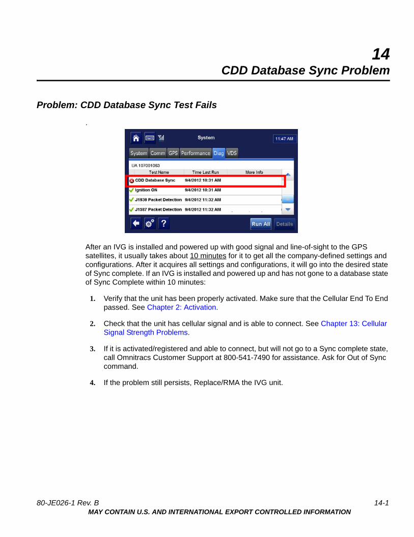
Problem: CDD Database Sync Test Fails
.
After an IVG is installed and powered up with good signal and line-of-sight to the GPS satellites, it usually takes about 10 minutes for it to get all the company-defined settings and configurations. After it acquires all settings and configurations, it will go into the desired state of Sync complete. If an IVG is installed and powered up and has not gone to a database state of Sync Complete within 10 minutes:
1. Verify that the unit has been properly activated. Make sure that the Cellular End To End passed. See Chapter 2: Activation.
2. Check that the unit has cellular signal and is able to connect. See Chapter 13: Cellular Signal Strength Problems.
3. If it is activated/registered and able to connect, but will not go to a Sync complete state, call Omnitracs Customer Support at 800-541-7490 for assistance. Ask for Out of Sync command.
4. If the problem still persists, Replace/RMA the IVG unit.
80-JE026-1 Rev. B 14-1MAY CONTAIN U.S. AND INTERNATIONAL EXPORT CONTROLLED INFORMATION

Problem: CDD Database Sync Test Fails CDD Database Sync Problem
14-2 80-JE026-1 Rev. BMAY CONTAIN U.S. AND INTERNATIONAL EXPORT CONTROLLED INFORMATION
15GPS Fix Problem
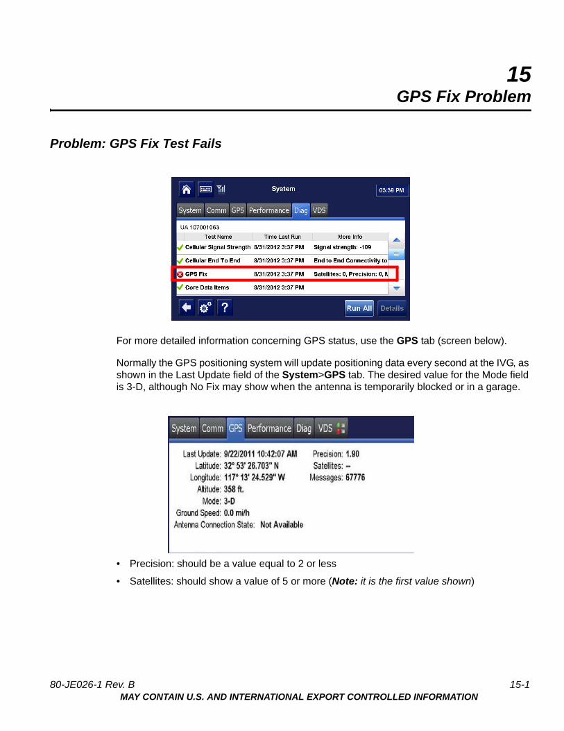
Problem: GPS Fix Test Fails
For more detailed information concerning GPS status, use the GPS tab (screen below).
Normally the GPS positioning system will update positioning data every second at the IVG, as shown in the Last Update field of the System>GPS tab. The desired value for the Mode field is 3-D, although No Fix may show when the antenna is temporarily blocked or in a garage.
• Precision: should be a value equal to 2 or less
• Satellites: should show a value of 5 or more (Note: it is the first value shown)
80-JE026-1 Rev. B 15-1MAY CONTAIN U.S. AND INTERNATIONAL EXPORT CONTROLLED INFORMATION
Problem: GPS Fix Test Fails GPS Fix Problem
If the vehicle is in the open with a clear view of the sky (no metal roof above), the mode should show 3-D. The Last Update time should be current, Precision should be <2 and at least 5 Satellites should be used in the fix. If this is not the case, follow the steps below:
1. Verify the IVG display is in a location where the view to the sky is not blocked or obstructed.
Check for any metal obstructions that may block or degrade the GPS signals, such as wires or cables directly above the display. If there are any obstructions, remove the obstructions or relocate the antenna.
The GPS screen has a couple of indicators which may point to a problem with obstruction:
• The Precision value should be <2. If it is consistently above 3.00, there is likely something interfering with the GPS signals.
• The Satellites field shows xx/yy, where xx is the number of satellites used in the position fix, and yy is the number of satellites recently viewed. The xx value should be 5 or greater. If it has a value less than 5, there is likely some obstruction.
15-2 80-JE026-1 Rev. BMAY CONTAIN U.S. AND INTERNATIONAL EXPORT CONTROLLED INFORMATION
16J1587 Packet Detection Problem
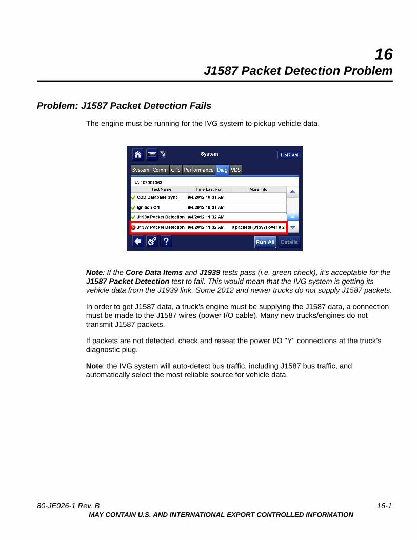
Problem: J1587 Packet Detection Fails
The engine must be running for the IVG system to pickup vehicle data.
Note: If the Core Data Items and J1939 tests pass (i.e. green check), it’s acceptable for the J1587 Packet Detection test to fail. This would mean that the IVG system is getting its vehicle data from the J1939 link. Some 2012 and newer trucks do not supply J1587 packets.
In order to get J1587 data, a truck’s engine must be supplying the J1587 data, a connection must be made to the J1587 wires (power I/O cable). Many new trucks/engines do not transmit J1587 packets.
If packets are not detected, check and reseat the power I/O "Y" connections at the truck’s diagnostic plug.
Note: the IVG system will auto-detect bus traffic, including J1587 bus traffic, and automatically select the most reliable source for vehicle data.
80-JE026-1 Rev. B 16-1MAY CONTAIN U.S. AND INTERNATIONAL EXPORT CONTROLLED INFORMATION

Problem: J1587 Packet Detection Fails J1587 Packet Detection Problem
16-2 80-JE026-1 Rev. BMAY CONTAIN U.S. AND INTERNATIONAL EXPORT CONTROLLED INFORMATION
17J1939 Packet Detection Problem
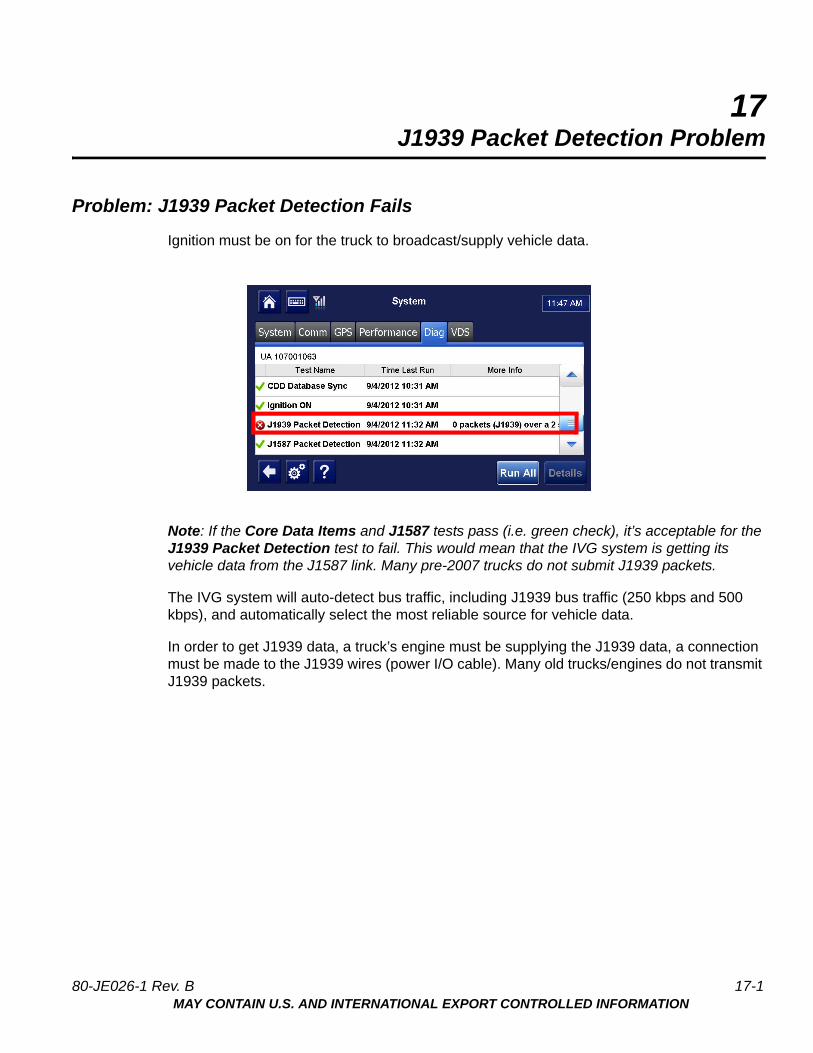
Problem: J1939 Packet Detection Fails
Ignition must be on for the truck to broadcast/supply vehicle data.
Note: If the Core Data Items and J1587 tests pass (i.e. green check), it’s acceptable for the J1939 Packet Detection test to fail. This would mean that the IVG system is getting its vehicle data from the J1587 link. Many pre-2007 trucks do not submit J1939 packets.
The IVG system will auto-detect bus traffic, including J1939 bus traffic (250 kbps and 500 kbps), and automatically select the most reliable source for vehicle data.
In order to get J1939 data, a truck’s engine must be supplying the J1939 data, a connection must be made to the J1939 wires (power I/O cable). Many old trucks/engines do not transmit J1939 packets.
80-JE026-1 Rev. B 17-1MAY CONTAIN U.S. AND INTERNATIONAL EXPORT CONTROLLED INFORMATION
Problem: J1939 Packet Detection Fails J1939 Packet Detection Problem
17-2 80-JE026-1 Rev. BMAY CONTAIN U.S. AND INTERNATIONAL EXPORT CONTROLLED INFORMATION

18Ignition On Detection Problem
Problem: Ignition On Test Fails
An IVG system will auto-detect when the ignition is on by identifying increased truck voltage and detecting enging RPMs. The engine must be running for the system to detect ignition is ON.
1. If the Ignition On test fails, it may be necessary to ensure the truck’s engine is running:
• It may be necessary to connect the ignition lead of the power I/O cable to a 12 VDC key switched to source. Ensure that wire is connected and secure.
• Verify the fuse in the ignition wire has not blown.
2. If it continues to fail, check the ignition source used and the associated truck fuse. Using a digital volt meter, verify that the source has approximately 12 VDC when key is in the ignition ON position and shows 0 VDC in the OFF position.
WARNING
You must connect the IVG ignition wire to a true switched ignition source, not an accessory source.
To confirm a true ignition source, use a digital volt meter to verify that the source has approximately 12 VDC when the key is in the ignition ON position and shows O VDC in the OFF and accessory position.
Note: Many newer model trucks have multiplex wiring systems that require specific ignition connection points. To ensure correct ignition connection points, refer to the individual Truck Specific Installation Instructions for more details.
80-JE026-1 Rev. B 18-1MAY CONTAIN U.S. AND INTERNATIONAL EXPORT CONTROLLED INFORMATION

Problem: Ignition On Test Fails Ignition On Detection Problem
18-2 80-JE026-1 Rev. BMAY CONTAIN U.S. AND INTERNATIONAL EXPORT CONTROLLED INFORMATION
19Core Data Problem
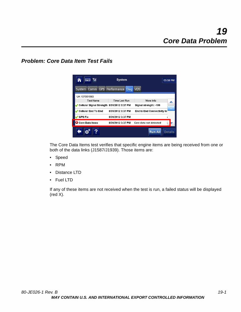
Problem: Core Data Item Test Fails
The Core Data Items test verifies that specific engine items are being received from one or both of the data links (J1587/J1939). Those items are:
• Speed
• RPM
• Distance LTD
• Fuel LTD
If any of these items are not received when the test is run, a failed status will be displayed (red X).
80-JE026-1 Rev. B 19-1MAY CONTAIN U.S. AND INTERNATIONAL EXPORT CONTROLLED INFORMATION
Problem: Core Data Item Test Fails Core Data Problem
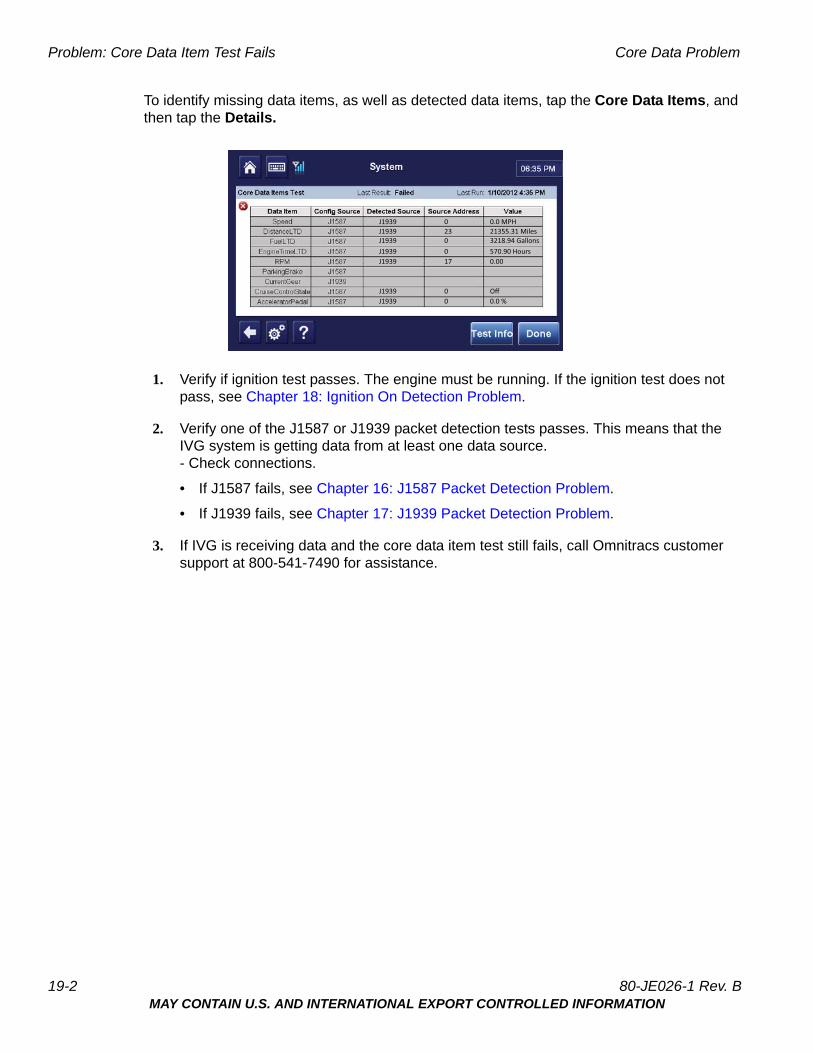
To identify missing data items, as well as detected data items, tap the Core Data Items, and then tap the Details.
1. Verify if ignition test passes. The engine must be running. If the ignition test does not pass, see Chapter 18: Ignition On Detection Problem.
2. Verify one of the J1587 or J1939 packet detection tests passes. This means that the IVG system is getting data from at least one data source.- Check connections.
• If J1587 fails, see Chapter 16: J1587 Packet Detection Problem.
• If J1939 fails, see Chapter 17: J1939 Packet Detection Problem.
3. If IVG is receiving data and the core data item test still fails, call Omnitracs customer support at 800-541-7490 for assistance.
J1939 0 0.0 MPH
0.0 %Off
0.00
21355.31 Miles3218.94 Gallons570.90 Hours
00
00
23
17
J1939J1939J1939J1939
J1939J1939
19-2 80-JE026-1 Rev. BMAY CONTAIN U.S. AND INTERNATIONAL EXPORT CONTROLLED INFORMATION

20IVG Display LED Indicators
IVG Display Performance—LED Indicators
In a normal operating environment:
• The top LED will be blinking blue.
• The middle LED will be blinking green:
State Top LED Middle LED Bottom LED Action
Normal Mode Blinking blue once per second
Blinking green once per 3 seconds
Not available None
Sleep Mode Blinking blue once every 12 seconds
OFF Not available None
Boot up and System Recovery Mode
Red and blue blink. Note: this should last no more than five minutes
A Red LED will blink ON and OFF at irregular frequencies. Note: this should last no more than 5 minutes.
Give unit five minutes to boot or recover
Give unit five minutes to boot or recover
80-JE026-1 Rev. B 20-1MAY CONTAIN U.S. AND INTERNATIONAL EXPORT CONTROLLED INFORMATION
IVG Display Performance—LED Indicators IVG Display LED Indicators
20-2 80-JE026-1 Rev. BMAY CONTAIN U.S. AND INTERNATIONAL EXPORT CONTROLLED INFORMATION
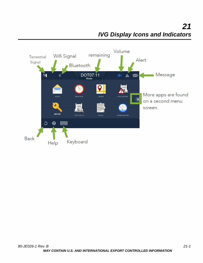
21IVG Display Icons and Indicators
80-JE026-1 Rev. B 21-1MAY CONTAIN U.S. AND INTERNATIONAL EXPORT CONTROLLED INFORMATION

IVG Display Icons and Indicators
80-JE026-1 Rev. B 21-2MAY CONTAIN U.S. AND INTERNATIONAL EXPORT CONTROLLED INFORMATION

22Performance Monitoring Troubleshooting
System Overview
Connecting to the truck’s data link using the power I/O cable is required for the Performance Monitoring application.
The Performance Monitoring application records data from the vehicle such as speed, distance, RPMs, and total fuel used.The data is retrieved from the truck by the IVG and sent to the host computer, either manually or automatically at preset intervals.
The hardware installation on the vehicle consists of connecting the IVG power I/O connector to the truck’s diagnostic connector.
Note: If the Performance Monitoring icon is grayed out, the Performance Monitoring application is not enabled. Call your company dispatch to have this application enabled.
Normal Performance
After the power I/O connection to the truck’s diagnostic connector has been made, company-defined parameters are sent and received by the unit, performance monitoring data will be recorded at the mobile and sent to the host system.
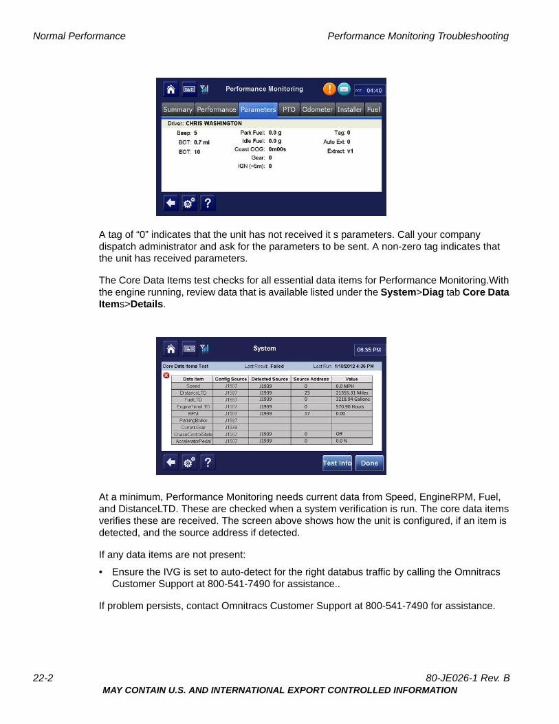
To confirm normal performance, first verify that performance monitoring parameters have been sent to the unit and received. Tap the Parameters tab within the Performance Monitoring application and verify the tag field is not “0.”
80-JE026-1 Rev. B 22-1MAY CONTAIN U.S. AND INTERNATIONAL EXPORT CONTROLLED INFORMATION
Normal Performance Performance Monitoring Troubleshooting
A tag of “0” indicates that the unit has not received it s parameters. Call your company dispatch administrator and ask for the parameters to be sent. A non-zero tag indicates that the unit has received parameters.
The Core Data Items test checks for all essential data items for Performance Monitoring.With the engine running, review data that is available listed under the System>Diag tab Core Data Items>Details.
At a minimum, Performance Monitoring needs current data from Speed, EngineRPM, Fuel, and DistanceLTD. These are checked when a system verification is run. The core data items verifies these are received. The screen above shows how the unit is configured, if an item is detected, and the source address if detected.
If any data items are not present:
• Ensure the IVG is set to auto-detect for the right databus traffic by calling the Omnitracs Customer Support at 800-541-7490 for assistance..
If problem persists, contact Omnitracs Customer Support at 800-541-7490 for assistance.
J1939 0 0.0 MPH
0.0 %Off
0.00
21355.31 Miles3218.94 Gallons570.90 Hours
00
00
23
17
J1939J1939J1939J1939
J1939J1939
22-2 80-JE026-1 Rev. BMAY CONTAIN U.S. AND INTERNATIONAL EXPORT CONTROLLED INFORMATION

Performance Monitoring Troubleshooting Normal Performance
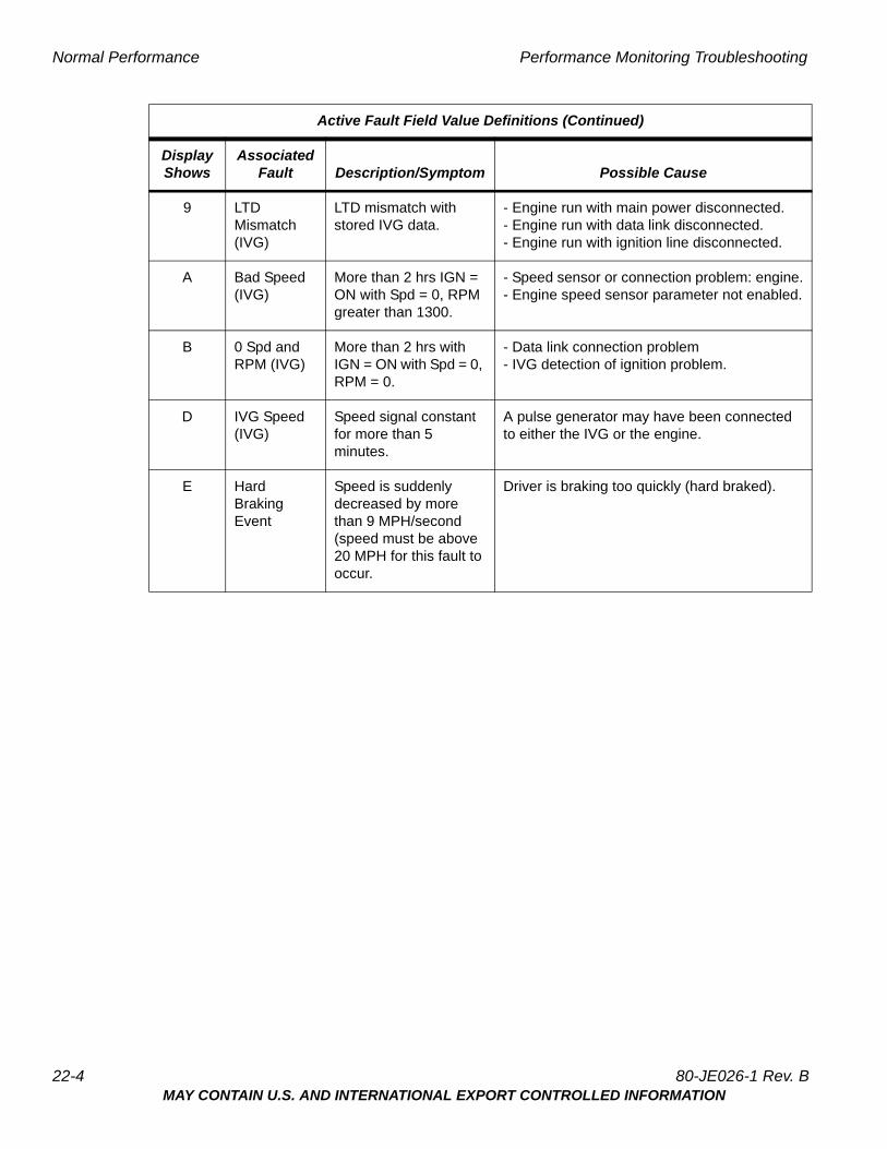
Performance Monitoring Faults and Descriptions
Monitored Active Faults are controlled by the customer-specified parameters sent to the unit. The following chart shows the faults that may surface.
Active Fault Field Value Definitions
DisplayShows
Associated Fault Description/Symptom Possible Cause
+ Fault no longer active Cleared
- Fault not monitored Performance monitoring parameters specified not to monitor.
0 No Power (IVG)
Power detected OFF for more than the wake-up time.
Main power was lost, causing the IVG to stay asleep longer than its wake-up interval.
1 RPM Zero (IVG)
RPM zero when speed is non-zero.
- RPM sensor or connection problem.- J1708 selection parameter set wrong.- In rare cases, no idle can be caused by faulty axle sensor input (e.g., wires reversed) causing a positive reading for speed while the vehicle is stationary.
2 Bad Ignition (IVG)
Ignition OFF and speed or RPM non-zero.
Problem with the IVG’s ignition sense or unit rebooted while moving.
3 RPM Sensor (IVG)
Engine posted PID (194) and PID (190).
RPM sensor or connection problem to the engine, detected by the engine’s diagnostics.
4 Speed Sensor (IVG)
Engine posted PID (194) and PID (84).
Speed sensor or connection problem to engine, detected by the engine’s diagnostics.
- - - - - - - - - -
80-JE026-1 Rev. B 22-3MAY CONTAIN U.S. AND INTERNATIONAL EXPORT CONTROLLED INFORMATION
Normal Performance Performance Monitoring Troubleshooting
9 LTD Mismatch (IVG)
LTD mismatch with stored IVG data.
- Engine run with main power disconnected.- Engine run with data link disconnected.- Engine run with ignition line disconnected.
A Bad Speed (IVG)
More than 2 hrs IGN = ON with Spd = 0, RPM greater than 1300.
- Speed sensor or connection problem: engine.- Engine speed sensor parameter not enabled.
B 0 Spd and RPM (IVG)
More than 2 hrs with IGN = ON with Spd = 0, RPM = 0.
- Data link connection problem- IVG detection of ignition problem.
D IVG Speed (IVG)
Speed signal constant for more than 5 minutes.
A pulse generator may have been connected to either the IVG or the engine.
E Hard Braking Event
Speed is suddenly decreased by more than 9 MPH/second (speed must be above 20 MPH for this fault to occur.
Driver is braking too quickly (hard braked).
Active Fault Field Value Definitions (Continued)
DisplayShows
Associated Fault Description/Symptom Possible Cause
22-4 80-JE026-1 Rev. BMAY CONTAIN U.S. AND INTERNATIONAL EXPORT CONTROLLED INFORMATION
23Critical Event Reporting Troubleshooting
Overview
Critical Event Reporting (CER) captures and reports vehicle critical event information (e.g., hard braking, vehicle speed, location, stability control (VDC), lane departure warning (LDW), and panic button events). With each hard braking event, five minutes of speed information is recorded and sent to the CER host system. Events are processed two minutes after they occur.
Normal Performance
In order for the CER feature to function, the IVG must be connected to the vehicle’s data link via the power I/O cable.
Critical events can be triggered by a:
• Hard Brake event
• Stability Control event (if available)
• Lane Departure Warning (LDW) (if option is installed)
• Manually triggered CER event.
Text-to-speech (TTS) can be enabled so CER events can be audibly conveyed to the driver.
Abnormal Performance
If any of the above items do not trigger a CER event, or if a critical event is reported in error, there is a problem. A problem is usually caused by one or more of the following:
• Loose or bad connection to the data link
• Intermittent data supplied by stability control device or lane departure warning device
• Intermittent data supplied by ECM of vehicle
80-JE026-1 Rev. B 23-1MAY CONTAIN U.S. AND INTERNATIONAL EXPORT CONTROLLED INFORMATION

Event Not Triggered Critical Event Reporting Troubleshooting
Event Not Triggered
CER Verify Configuration
1. To access CER information, go to the Home screen and tap the Critical Event Reporting button. If this button is grayed out, then CER service for the unit must be enabled from the Customer Portal.
2. A pop-up will appear. Tap the Diagnostics button at the bottom right of the screen.
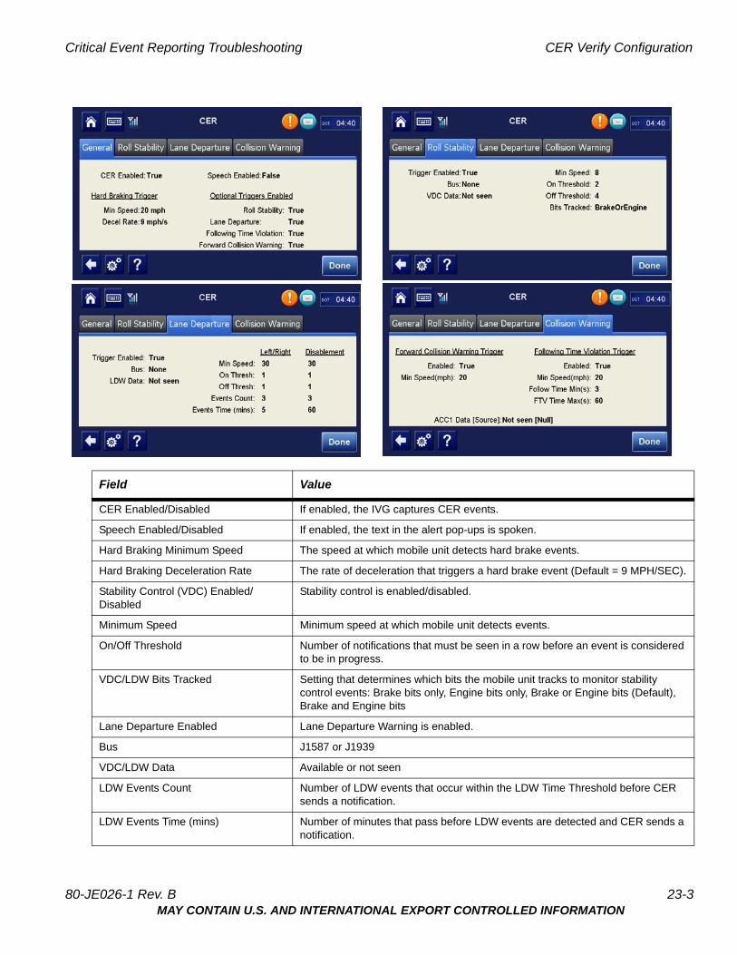
3. Select one of the tabs for General, Roll Stability, Lane Departure information, or Collision Warning.
23-2 80-JE026-1 Rev. BMAY CONTAIN U.S. AND INTERNATIONAL EXPORT CONTROLLED INFORMATION
Critical Event Reporting Troubleshooting CER Verify Configuration
Field Value
CER Enabled/Disabled If enabled, the IVG captures CER events.
Speech Enabled/Disabled If enabled, the text in the alert pop-ups is spoken.
Hard Braking Minimum Speed The speed at which mobile unit detects hard brake events.
Hard Braking Deceleration Rate The rate of deceleration that triggers a hard brake event (Default = 9 MPH/SEC).
Stability Control (VDC) Enabled/Disabled
Stability control is enabled/disabled.
Minimum Speed Minimum speed at which mobile unit detects events.
On/Off Threshold Number of notifications that must be seen in a row before an event is considered to be in progress.
VDC/LDW Bits Tracked Setting that determines which bits the mobile unit tracks to monitor stability control events: Brake bits only, Engine bits only, Brake or Engine bits (Default), Brake and Engine bits
Lane Departure Enabled Lane Departure Warning is enabled.
Bus J1587 or J1939
VDC/LDW Data Available or not seen
LDW Events Count Number of LDW events that occur within the LDW Time Threshold before CER sends a notification.
LDW Events Time (mins) Number of minutes that pass before LDW events are detected and CER sends a notification.
80-JE026-1 Rev. B 23-3MAY CONTAIN U.S. AND INTERNATIONAL EXPORT CONTROLLED INFORMATION
Sending a Manual CER Event Critical Event Reporting Troubleshooting
Hard braking gets information from either J1708/1587 or J1939. One of the two indicator lights must be green to record hard braking events correctly. Some filtering is done to prevent erroneous CER events due to faulty truck speed sensors.
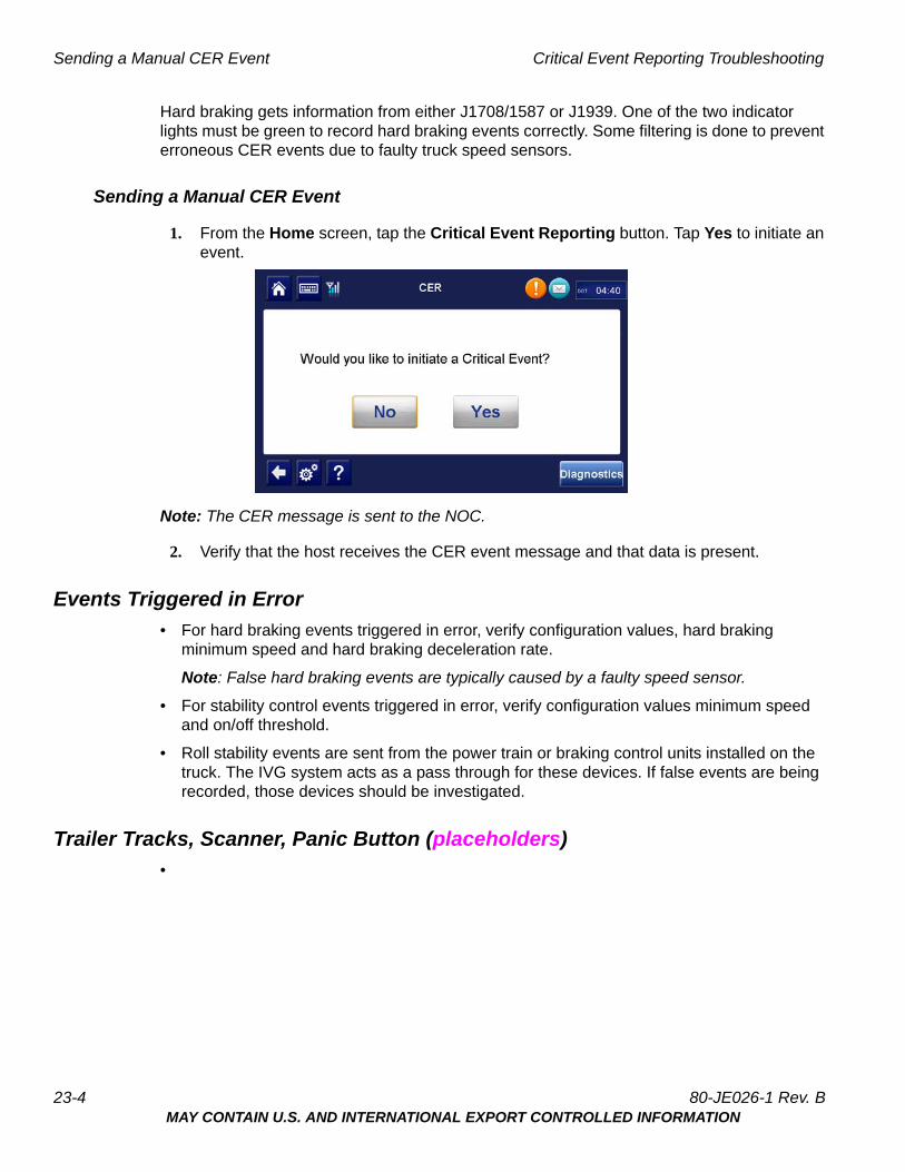
Sending a Manual CER Event
1. From the Home screen, tap the Critical Event Reporting button. Tap Yes to initiate an event.
Note: The CER message is sent to the NOC.
2. Verify that the host receives the CER event message and that data is present.
Events Triggered in Error
• For hard braking events triggered in error, verify configuration values, hard braking minimum speed and hard braking deceleration rate.
Note: False hard braking events are typically caused by a faulty speed sensor.
• For stability control events triggered in error, verify configuration values minimum speed and on/off threshold.
• Roll stability events are sent from the power train or braking control units installed on the truck. The IVG system acts as a pass through for these devices. If false events are being recorded, those devices should be investigated.
Trailer Tracks, Scanner, Panic Button (placeholders)
•
23-4 80-JE026-1 Rev. BMAY CONTAIN U.S. AND INTERNATIONAL EXPORT CONTROLLED INFORMATION
24Optional Accessories Troubleshooting
This section reserved for future use.
80-JE026-1 Rev. B 24-1MAY CONTAIN U.S. AND INTERNATIONAL EXPORT CONTROLLED INFORMATION

Optional Accessories Troubleshooting
24-2 80-JE026-1 Rev. BMAY CONTAIN U.S. AND INTERNATIONAL EXPORT CONTROLLED INFORMATION

Appendix Contents
A. Wiring Diagrams and Charts
B. Environmental and Power Requirements
C. General Wiring and Installation Guidelines
D. Standard RMA Procedure
E. Upgrading the IVG Using USB Memory Sticks
F. Preventive Maintenance Inspection
G. Component Information
H. Installation Form
I. RF Exposure Information (SAR)
80-JE026-1 Rev. BMAY CONTAIN U.S. AND INTERNATIONAL EXPORT CONTROLLED INFORMATION

Appendix Contents
80-JE026-1 Rev. BMAY CONTAIN U.S. AND INTERNATIONAL EXPORT CONTROLLED INFORMATION
AWiring Diagrams and Charts
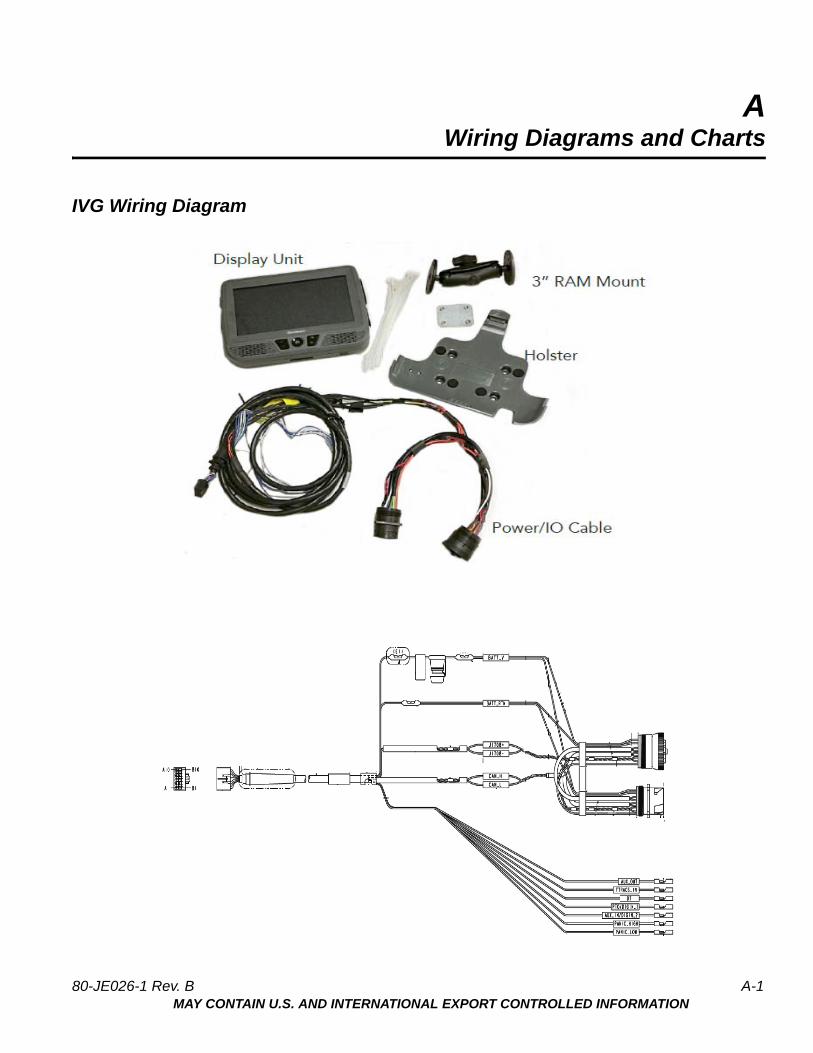
IVG Wiring Diagram
80-JE026-1 Rev. B A-1MAY CONTAIN U.S. AND INTERNATIONAL EXPORT CONTROLLED INFORMATION
IVG Wiring Diagram Wiring Diagrams and Charts
A-2 80-JE026-1 Rev. BMAY CONTAIN U.S. AND INTERNATIONAL EXPORT CONTROLLED INFORMATION
Wiring Diagrams and Charts 6-pin Power/IO Cable
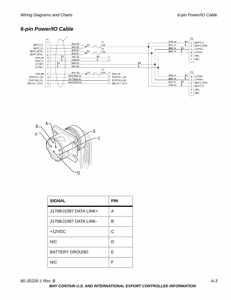
6-pin Power/IO Cable
SIGNAL PIN
J1708/J1587 DATA LINK+ A
J1708/J1587 DATA LINK- B
+12VDC C
N/C D
BATTERY GROUND E
N/C F
80-JE026-1 Rev. B A-3MAY CONTAIN U.S. AND INTERNATIONAL EXPORT CONTROLLED INFORMATION
9-pin Power/IO Cable and Paccar Adapter Cable Wiring Diagrams and Charts
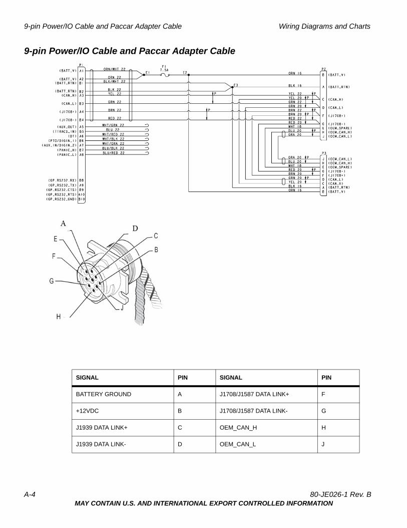
9-pin Power/IO Cable and Paccar Adapter Cable
SIGNAL PIN SIGNAL PIN
BATTERY GROUND A J1708/J1587 DATA LINK+ F
+12VDC B J1708/J1587 DATA LINK- G
J1939 DATA LINK+ C OEM_CAN_H H
J1939 DATA LINK- D OEM_CAN_L J
A-4 80-JE026-1 Rev. BMAY CONTAIN U.S. AND INTERNATIONAL EXPORT CONTROLLED INFORMATION
Wiring Diagrams and Charts Volvo/Mack 2014 or newer OBDII style Connector
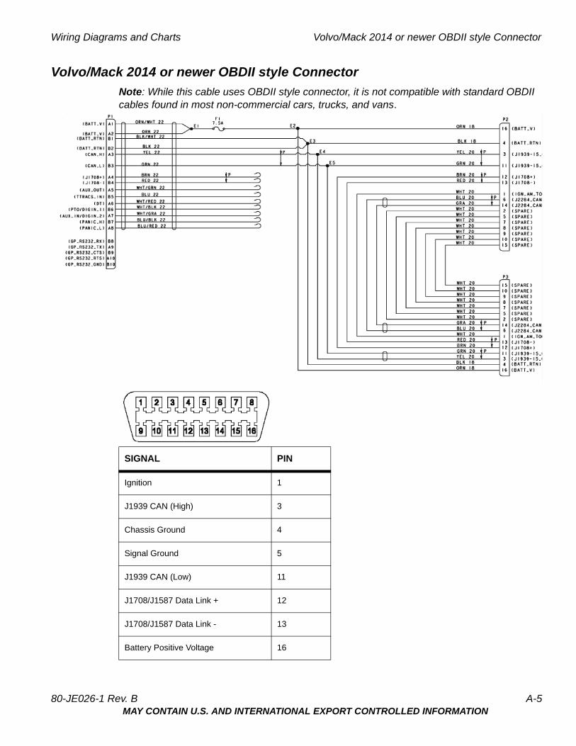
Volvo/Mack 2014 or newer OBDII style Connector
Note: While this cable uses OBDII style connector, it is not compatible with standard OBDII cables found in most non-commercial cars, trucks, and vans.
SIGNAL PIN
Ignition 1
J1939 CAN (High) 3
Chassis Ground 4
Signal Ground 5
J1939 CAN (Low) 11
J1708/J1587 Data Link + 12
J1708/J1587 Data Link - 13
Battery Positive Voltage 16
80-JE026-1 Rev. B A-5MAY CONTAIN U.S. AND INTERNATIONAL EXPORT CONTROLLED INFORMATION
Hino Wiring Diagrams and Charts
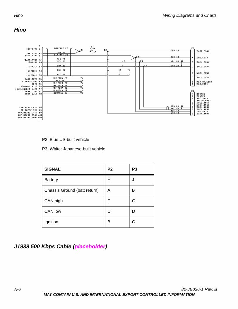
Hino
P2: Blue US-built vehicle
P3: White: Japanese-built vehicle
J1939 500 Kbps Cable (placeholder)
SIGNAL P2 P3
Battery H J
Chassis Ground (batt return) A B
CAN high F G
CAN low C D
Ignition B C
A-6 80-JE026-1 Rev. BMAY CONTAIN U.S. AND INTERNATIONAL EXPORT CONTROLLED INFORMATION
BEnvironmental and Power Requirements
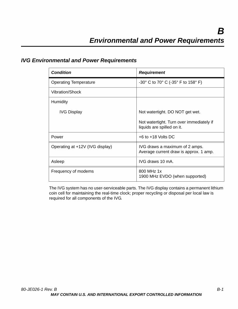
IVG Environmental and Power Requirements
The IVG system has no user-serviceable parts. The IVG display contains a permanent lithium coin cell for maintaining the real-time clock; proper recycling or disposal per local law is required for all components of the IVG.
Condition Requirement
Operating Temperature -30° C to 70° C (-35° F to 158° F)
Vibration/Shock
Humidity
IVG Display Not watertight. DO NOT get wet.
Not watertight. Turn over immediately if liquids are spilled on it.
Power +6 to +18 Volts DC
Operating at +12V (IVG display) IVG draws a maximum of 2 amps.Average current draw is approx. 1 amp.
Asleep IVG draws 10 mA.
Frequency of modems 800 MHz 1x1900 MHz EVDO (when supported)
80-JE026-1 Rev. B B-1MAY CONTAIN U.S. AND INTERNATIONAL EXPORT CONTROLLED INFORMATION
IVG Environmental and Power Requirements Environmental and Power Requirements
B-2 80-JE026-1 Rev. BMAY CONTAIN U.S. AND INTERNATIONAL EXPORT CONTROLLED INFORMATION

CGeneral Wiring and Installation Guidelines
Making Electrical Connections - Standard Installations
For standard IVG installations, the only electrical connection needed to the truck will be the power I/O cable and an ignition wire lead.
Cutting and Splicing Power I/O Cable - Non-standard Installation
Some trucks may use a different 9-pin diagnostic connector than supplied on the Omnitracs “Y” cable. The connector on the Omnitracs cable may not easily mount in the dash. Therefore, it may be necessary to make direct butt splice connections.
If the available power I/O cable does not mate to the truck’s diagnostic connector, the “Y” portion of the cable can be cut off and the leads spliced into an appropriate source:
Cable TruckBATT_V 12 VDC unswitched sourceBATT_RTN Chassis groundJ1708+ Positive J1587/J1708 truck wireJ1708- Negaive J1587/J1708 truck wireCan_H J1939+ truck wire (yellow to yellow)Can_L J1939- truck wire (green to green)
80-JE026-1 Rev. B C-1MAY CONTAIN U.S. AND INTERNATIONAL EXPORT CONTROLLED INFORMATION
Approved Omnitracs Electrical Connectors General Wiring and Installation Guidelines
Approved Omnitracs Electrical Connectors
The wiring for the IVG system is expected to be inside the cab. The only Omnitracs-approved electrical connections other than standard connectors are crimp butt splices and crimp ring terminals. Connections are typically made by mating the two connectors. Many of the following general guidelines apply to non-standard IVG connections where the power I/O cable must be cut because it does easily mount in the truck’s dashboard.
Caution
Not following proper wiring guidelines and using improper crimps and butt splices may cause intermittent connections and may result in unexpected truck down time or system failure.
Wire Stripping
Caution
Use care in stripping wires. Vibration can cause nicked wires to fail. Using wire cutters, knives, or other tools can damage the conductor wire and/or insulation.
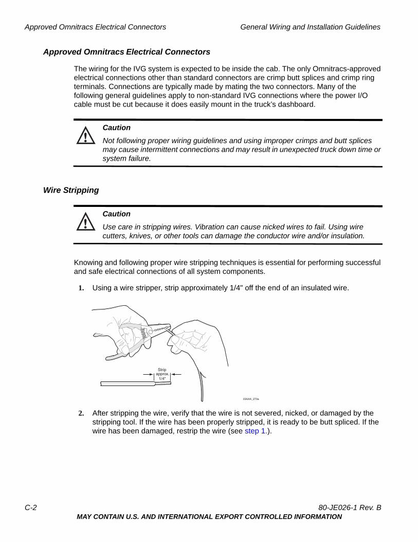
Knowing and following proper wire stripping techniques is essential for performing successful and safe electrical connections of all system components.
1. Using a wire stripper, strip approximately 1/4" off the end of an insulated wire.
2. After stripping the wire, verify that the wire is not severed, nicked, or damaged by the stripping tool. If the wire has been properly stripped, it is ready to be butt spliced. If the wire has been damaged, restrip the wire (see step 1.).
1/4"approx.Strip
03AAA_270a
C-2 80-JE026-1 Rev. BMAY CONTAIN U.S. AND INTERNATIONAL EXPORT CONTROLLED INFORMATION

General Wiring and Installation Guidelines Butt Splicing
Butt Splicing
• Omnitracs recommends Nylon insulated, seamless butt connectors with inspection windows.
• Heat-shrinkable butt connectors are preferred.
Make sure the size of the butt splice is appropriate for the job. A good butt splice has these characteristics:
• The ends of the bare wires are visible through an inspection window.
• The ends of the wires “butt” up against the stop.
• The wires are not exposed beyond splice shielding.
• Crimping does not sever or damage the wires or insulation.
80-JE026-1 Rev. B C-3MAY CONTAIN U.S. AND INTERNATIONAL EXPORT CONTROLLED INFORMATION
Crimping General Wiring and Installation Guidelines
Crimping
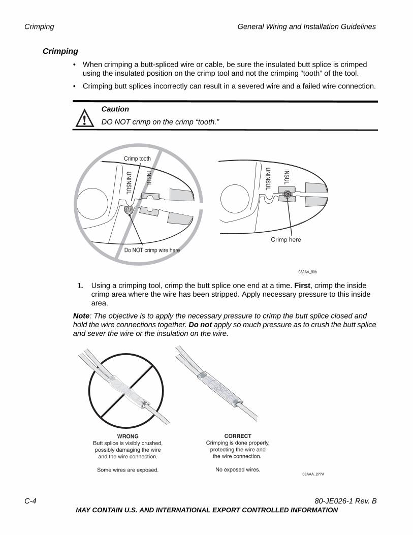
• When crimping a butt-spliced wire or cable, be sure the insulated butt splice is crimped using the insulated position on the crimp tool and not the crimping “tooth” of the tool.
• Crimping butt splices incorrectly can result in a severed wire and a failed wire connection.
Caution
DO NOT crimp on the crimp “tooth.”
1. Using a crimping tool, crimp the butt splice one end at a time. First, crimp the inside crimp area where the wire has been stripped. Apply necessary pressure to this inside area.
Note: The objective is to apply the necessary pressure to crimp the butt splice closed and hold the wire connections together. Do not apply so much pressure as to crush the butt splice and sever the wire or the insulation on the wire.
03AAA_90b
Crimp tooth
INSU
L
Do NOT crimp wire here
Crimp here
INSU
L
UN
INSU
L
UN
INSU
L
WRONGButt splice is visibly crushed,possibly damaging the wire
and the wire connection.
Some wires are exposed.
CORRECTCrimping is done properly,
protecting the wire andthe wire connection.
No exposed wires.03AAA_277A
C-4 80-JE026-1 Rev. BMAY CONTAIN U.S. AND INTERNATIONAL EXPORT CONTROLLED INFORMATION
General Wiring and Installation Guidelines Crimping
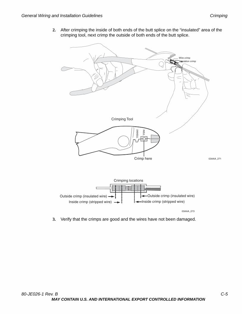
2. After crimping the inside of both ends of the butt splice on the “insulated” area of the crimping tool, next crimp the outside of both ends of the butt splice.
3. Verify that the crimps are good and the wires have not been damaged.
03AAA_271Crimp here
Crimping Tool
INSU
L
UN
INSU
L
Wire crimp
Crimping locations
Inside crimp (stripped wire)
Outside crimp (insulated wire)
03AAA_273
Outside crimp (insulated wire)
Inside crimp (stripped wire)
80-JE026-1 Rev. B C-5MAY CONTAIN U.S. AND INTERNATIONAL EXPORT CONTROLLED INFORMATION
Ring Terminals General Wiring and Installation Guidelines
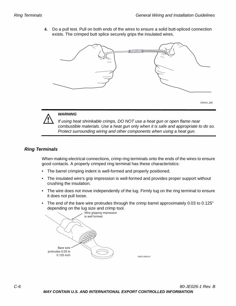
4. Do a pull test. Pull on both ends of the wires to ensure a solid butt-spliced connection exists. The crimped butt splice securely grips the insulated wires.
WARNING
If using heat shrinkable crimps, DO NOT use a heat gun or open flame near combustible materials. Use a heat gun only when it is safe and appropriate to do so. Protect surrounding wiring and other components when using a heat gun.
Ring Terminals
When making electrical connections, crimp ring terminals onto the ends of the wires to ensure good contacts. A properly crimped ring terminal has these characteristics:
• The barrel crimping indent is well-formed and properly positioned.
• The insulated wire’s grip impression is well-formed and provides proper support without crushing the insulation.
• The wire does not move independently of the lug. Firmly tug on the ring terminal to ensure it does not pull loose.
• The end of the bare wire protrudes through the crimp barrel approximately 0.03 to 0.125" depending on the lug size and crimp tool.
03AAA_282
Wire gripping impressionis well formed
Bare wireprotrudes 0.03 to
0.125 inch OM/E-0093-97
C-6 80-JE026-1 Rev. BMAY CONTAIN U.S. AND INTERNATIONAL EXPORT CONTROLLED INFORMATION
General Wiring and Installation Guidelines Proper Grounding
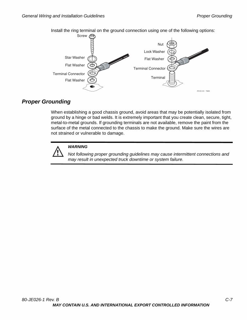
Install the ring terminal on the ground connection using one of the following options:
Proper Grounding
When establishing a good chassis ground, avoid areas that may be potentially isolated from ground by a hinge or bad welds. It is extremely important that you create clean, secure, tight, metal-to-metal grounds. If grounding terminals are not available, remove the paint from the surface of the metal connected to the chassis to make the ground. Make sure the wires are not strained or vulnerable to damage.
WARNING
Not following proper grounding guidelines may cause intermittent connections and may result in unexpected truck downtime or system failure.
Flat Washer
Flat Washer
Flat Washer
Star Washer
Lock Washer
Nut
Terminal Connector
Terminal Connector
Terminal
Screw
03AAA 285
80-JE026-1 Rev. B C-7MAY CONTAIN U.S. AND INTERNATIONAL EXPORT CONTROLLED INFORMATION

General Installation Guidelines General Wiring and Installation Guidelines
General Installation Guidelines
• Determine the most direct and protected route when routing cables to connect the components to each other and to the vehicle.
• Do not trim cable lengths to fit a specific vehicle.
• Use only wire strippers for stripping wires.
• Use only the appropriate insulated crimping tool for crimping insulated connectors.
• Use existing holes for cable routing whenever possible.
• Avoid running cable over or near heat sources.
Routing and Protecting Cables
• Provide strain relief for all cables
• Use tie wraps
• Debur any drilled holes
DO NOT route cables:
• Near audio system amplifiers
• Near exhaust pipes and other sources of heat
• Near the brake, clutch, or accelerator pedals, and linkage
• Near foot traffic areas
• Near the windshield wiper mechanism
• Near CB radio wires
• Over sharp edges
• Over moving parts
Special Interior Routing Guidelines
• Route cables under kick plates or carpets.
• Avoid high foot traffic areas.
• When reinstalling dash panels, be careful that screws do not penetrate cables.
• Route cables with any existing vehicle cables.
Storing Excess Cabling
• Secure excess cabling with tie wraps.
• Stow out of sight.
Stress Relief
• Ensure cables have enough slack so connections are not being pulled.
C-8 80-JE026-1 Rev. BMAY CONTAIN U.S. AND INTERNATIONAL EXPORT CONTROLLED INFORMATION
DStandard RMA Procedure
For customers, to return failed equipment, go to Omnitracs Customer Portal at https://customer.omnitracs.com
For service centers only, please return equipment to Omnitracs at the following address. Make sure that the RMA number is marked clearly on the outside of the box.
Omnitracs, LLC - RMA Receivingc/o Baja Freight Forwarders, Inc.8662 Siempre Viva RoadSan Diego, CA 92154RMA #: __________________(800) 541-7490
To prevent damage during shipment and handling, carefully package all equipment being returned. If the original shipping container and packing material are available, please use them to return the equipment.
80-JE026-1 Rev. B D-1MAY CONTAIN U.S. AND INTERNATIONAL EXPORT CONTROLLED INFORMATION

Standard RMA Procedure
D-2 80-JE026-1 Rev. BMAY CONTAIN U.S. AND INTERNATIONAL EXPORT CONTROLLED INFORMATION
EUpgrading the IVG Using USB Memory Sticks
Before You Start
During an OS or application upgrade, driver and vehicle information can be deleted. The list below will help minimize any inconvenience this causes.
• Confirm that the driver knows that all stored messages will be lost.
The driver should write down any information he thinks he may need later, from both his inbox and his outbox.
• Confirm that he has listened to any unopened audio files.
This is necessary only if your company uses Omnitracs Media Manager application. Deleted audio files will not be resent to the vehicle.
• Determine if certain special services are enabled for this vehicle.
From the display unit’s Home screen, check to see if the following services are accessible:
- Driver Workflow
- Content Delivery
- Hours of Service
- Navigation
- Performance Monitoring
Requirements for Certain Services
For everything except Hours of Service and Navigation, there are required tasks that you or someone else must complete before the upgrade. If you don’t, important data may be lost.
Driver Workflow: The trip plan and any pre-plans will be deleted during the upgrade.
• Before: The driver should write down the details of the next stop in the trip plan.
• After the upgrade: the driver should ask dispatch to resend the current trip plan and any pre-plans.
Hours of Service: Normally, no HOS data will be lost.
• Before: none. The driver’s logs are sent to the company’s HOS database when the driver logs off the unit.
• After the upgrade: the logs are automatically resent to the vehicle the next time the driver logs into HOS. Remind the driver that he needs to account for his time during the upgrade and record the proper duty status. Recommend that the driver pay special attention to that day the next time he approves the logs.
80-JE026-1 Rev. B E-1MAY CONTAIN U.S. AND INTERNATIONAL EXPORT CONTROLLED INFORMATION

Requirements for Certain Services Upgrading the IVG Using USB Memory Sticks
Navigation: The current route will be deleted during the upgrade.
• Before: None.
• After the upgrade: The driver needs to ask dispatch to resend the list of stops for the current trip.
Performance Monitoring: Performance Monitoring data on the unit is deleted during an upgrade.
• Before: Your company’s System Administrator needs to take steps to ensure the data is not lost by manually extracting the performance data stored in the vehicle’s IVG system. For the Omnitracs Services Portal, instructions are in Performance Monitoring: Administration and Configuration Guide (80-JA316-3). For AS/400®, they can refer to the SensorTRACS/400 User's Guide, Version 2.3 (80-30597-4). Remind Operations that your Omnitracs representative can also help the System Administrators with this task.
• After the upgrade: Contact Operations and have a System Administrator resend the vehicle’s Performance Monitoring parameters.
E-2 80-JE026-1 Rev. BMAY CONTAIN U.S. AND INTERNATIONAL EXPORT CONTROLLED INFORMATION
Upgrading the IVG Using USB Memory Sticks Placeholder - new process screens available soon
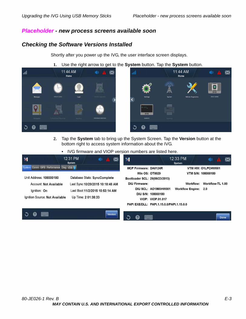
Placeholder - new process screens available soon
Checking the Software Versions Installed
Shortly after you power up the IVG, the user interface screen displays.
1. Use the right arrow to get to the System button. Tap the System button.
2. Tap the System tab to bring up the System Screen. Tap the Version button at the bottom right to access system information about the IVG.
• IVG firmware and VIOP version numbers are listed here.
80-JE026-1 Rev. B E-3MAY CONTAIN U.S. AND INTERNATIONAL EXPORT CONTROLLED INFORMATION
Upgrading Only the IVG Firmware Upgrading the IVG Using USB Memory Sticks
Upgrading Only the IVG Firmware
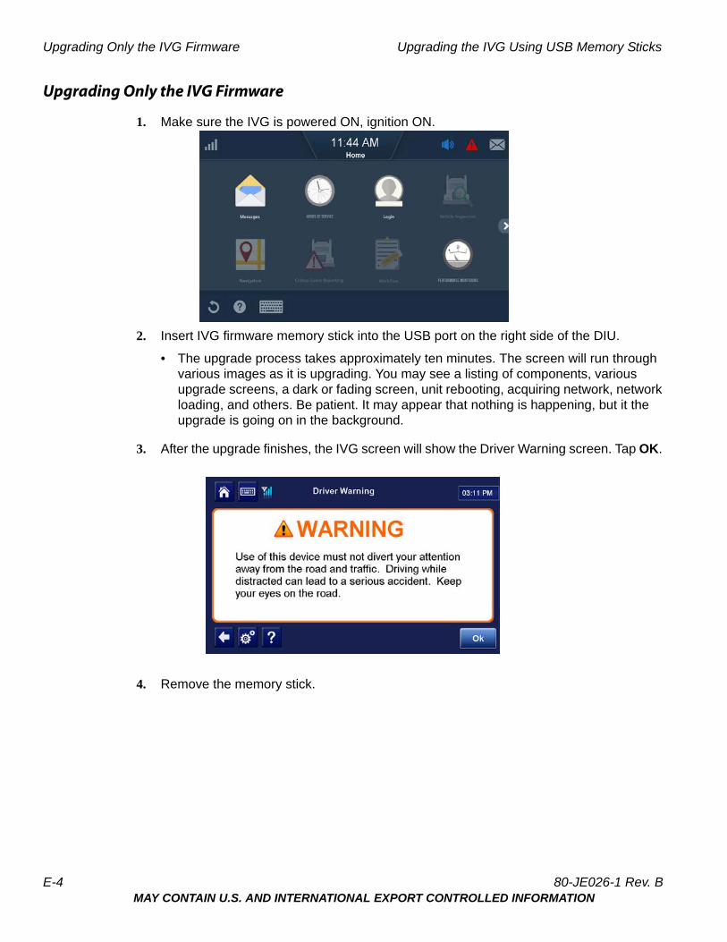
1. Make sure the IVG is powered ON, ignition ON.
2. Insert IVG firmware memory stick into the USB port on the right side of the DIU.
• The upgrade process takes approximately ten minutes. The screen will run through various images as it is upgrading. You may see a listing of components, various upgrade screens, a dark or fading screen, unit rebooting, acquiring network, network loading, and others. Be patient. It may appear that nothing is happening, but it the upgrade is going on in the background.
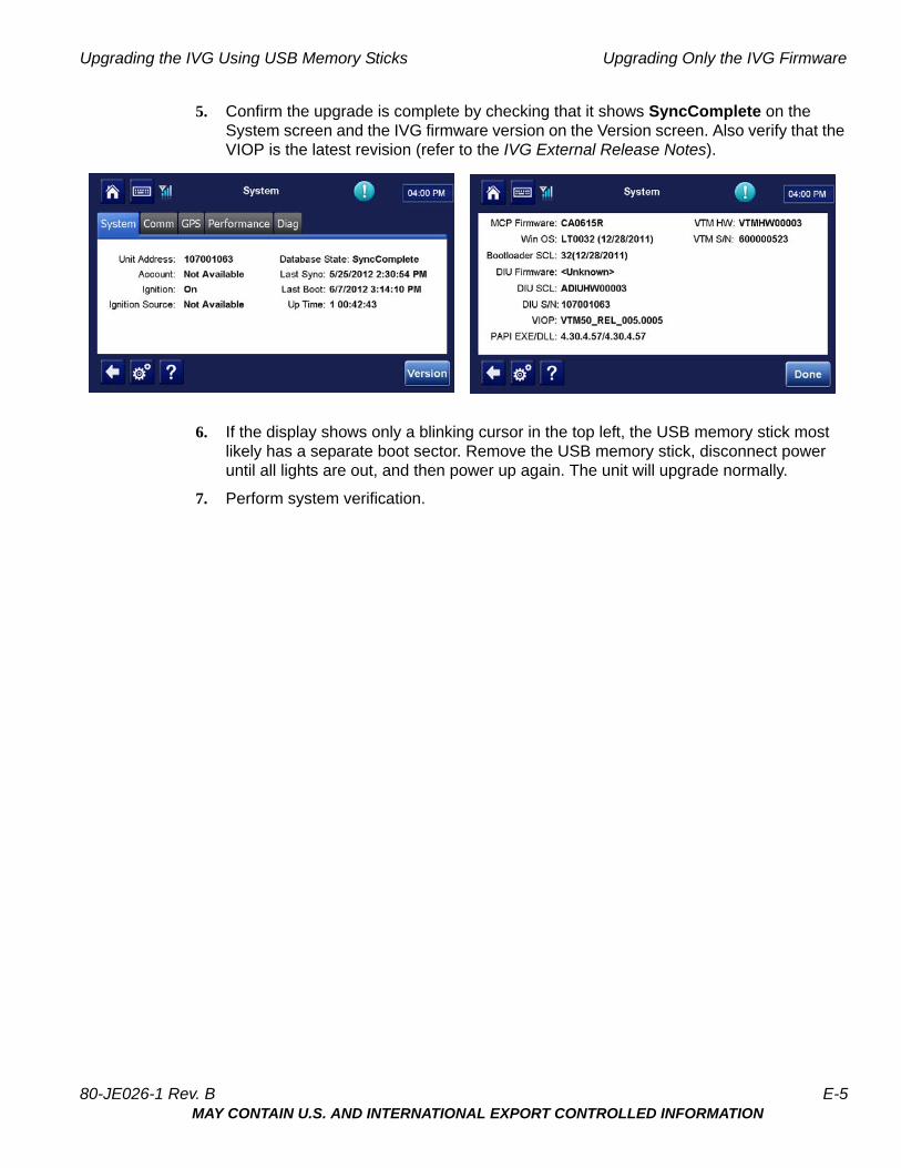
3. After the upgrade finishes, the IVG screen will show the Driver Warning screen. Tap OK.
4. Remove the memory stick.
E-4 80-JE026-1 Rev. BMAY CONTAIN U.S. AND INTERNATIONAL EXPORT CONTROLLED INFORMATION
Upgrading the IVG Using USB Memory Sticks Upgrading Only the IVG Firmware
5. Confirm the upgrade is complete by checking that it shows SyncComplete on the System screen and the IVG firmware version on the Version screen. Also verify that the VIOP is the latest revision (refer to the IVG External Release Notes).
6. If the display shows only a blinking cursor in the top left, the USB memory stick most likely has a separate boot sector. Remove the USB memory stick, disconnect power until all lights are out, and then power up again. The unit will upgrade normally.
7. Perform system verification.
80-JE026-1 Rev. B E-5MAY CONTAIN U.S. AND INTERNATIONAL EXPORT CONTROLLED INFORMATION

Upgrading Only the IVG Firmware Upgrading the IVG Using USB Memory Sticks
E-6 80-JE026-1 Rev. BMAY CONTAIN U.S. AND INTERNATIONAL EXPORT CONTROLLED INFORMATION
FPreventive Maintenance Inspection
How Often Should Inspections Be Performed?
• Omnitracs recommends inspections be performed at least once every 90 days.
• During normally scheduled vehicle preventive maintenance inspections.
Performing System Verification
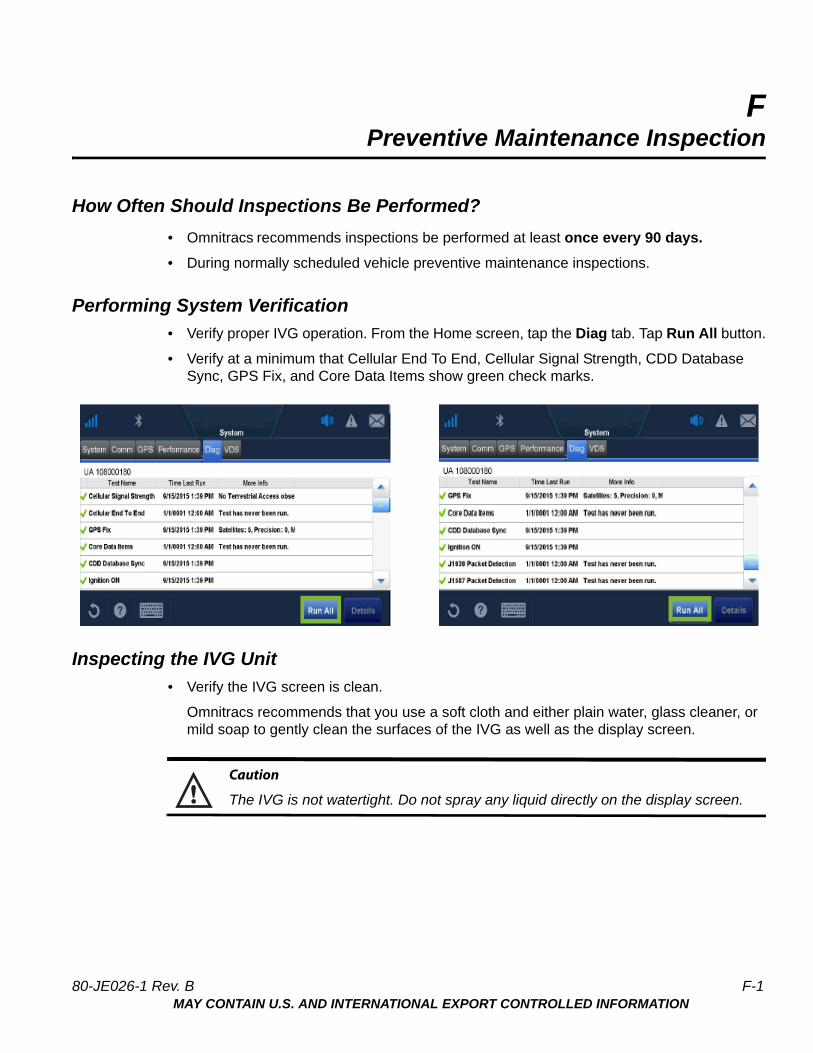
• Verify proper IVG operation. From the Home screen, tap the Diag tab. Tap Run All button.
• Verify at a minimum that Cellular End To End, Cellular Signal Strength, CDD Database Sync, GPS Fix, and Core Data Items show green check marks.
Inspecting the IVG Unit
• Verify the IVG screen is clean.
Omnitracs recommends that you use a soft cloth and either plain water, glass cleaner, or mild soap to gently clean the surfaces of the IVG as well as the display screen.
Caution
The IVG is not watertight. Do not spray any liquid directly on the display screen.
80-JE026-1 Rev. B F-1MAY CONTAIN U.S. AND INTERNATIONAL EXPORT CONTROLLED INFORMATION
Inspecting the IVG Unit Preventive Maintenance Inspection
Heavily soiled IVG units should be returned to Omnitracs using the RMA process for proper cleaning.
Note: Use the PDA stylus, provided with the unit, or your fingers to navigate the IVG display.
Do not use pencils, pens, metal objects, or any other devices which could possibly scratch the touchscreen.
• Make sure the display cable is not a tripping hazard.
• Verify the display screen is readable in any lighting condition.
• Make sure the display cable has enough slack and is not being rubbed or cut by anything inside the cab.
• Remove the IVG from the holster and make sure the screws holding the holster in place are secure.
Note: Display cable must not be removed from the IVG or warranty will be voided.
F-2 80-JE026-1 Rev. BMAY CONTAIN U.S. AND INTERNATIONAL EXPORT CONTROLLED INFORMATION
GComponent Information
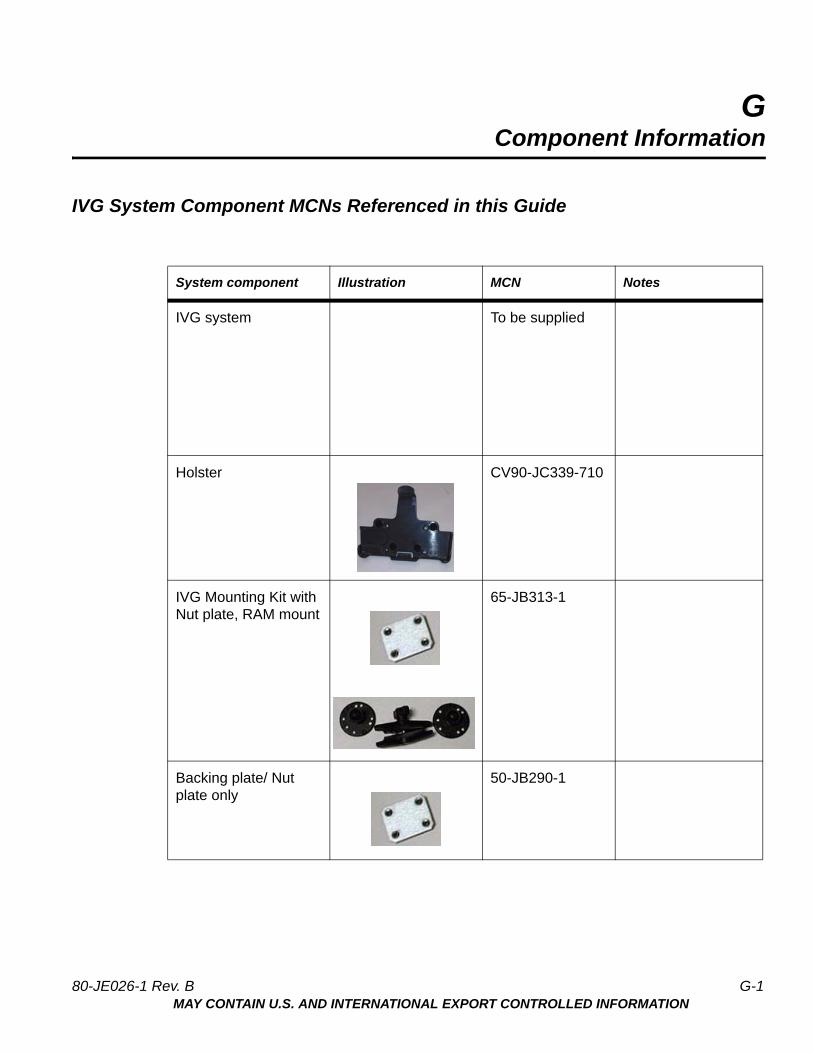
IVG System Component MCNs Referenced in this Guide
System component Illustration MCN Notes
IVG system To be supplied
Holster CV90-JC339-710
IVG Mounting Kit with Nut plate, RAM mount
65-JB313-1
Backing plate/ Nut plate only
50-JB290-1
80-JE026-1 Rev. B G-1MAY CONTAIN U.S. AND INTERNATIONAL EXPORT CONTROLLED INFORMATION
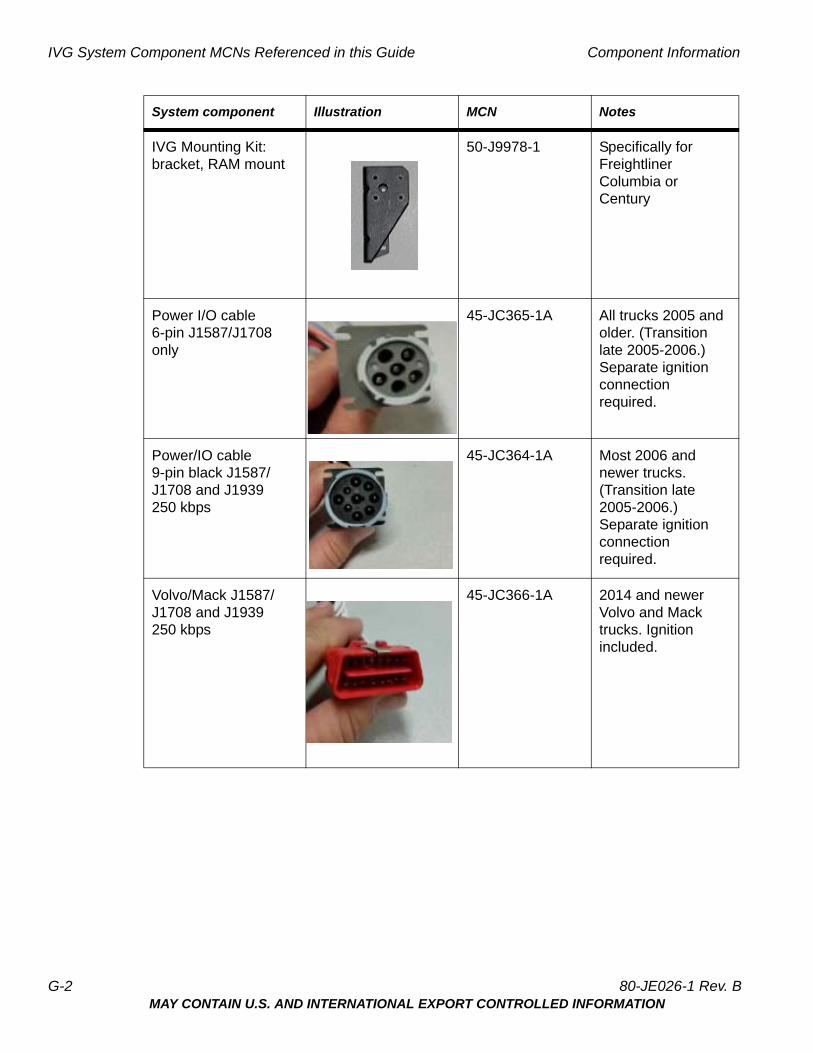
IVG System Component MCNs Referenced in this Guide Component Information
IVG Mounting Kit: bracket, RAM mount
50-J9978-1 Specifically for Freightliner Columbia or Century
Power I/O cable 6-pin J1587/J1708 only
45-JC365-1A All trucks 2005 and older. (Transition late 2005-2006.) Separate ignition connection required.
Power/IO cable 9-pin black J1587/J1708 and J1939 250 kbps
45-JC364-1A Most 2006 and newer trucks. (Transition late 2005-2006.) Separate ignition connection required.
Volvo/Mack J1587/J1708 and J1939 250 kbps
45-JC366-1A 2014 and newer Volvo and Mack trucks. Ignition included.
System component Illustration MCN Notes
G-2 80-JE026-1 Rev. BMAY CONTAIN U.S. AND INTERNATIONAL EXPORT CONTROLLED INFORMATION
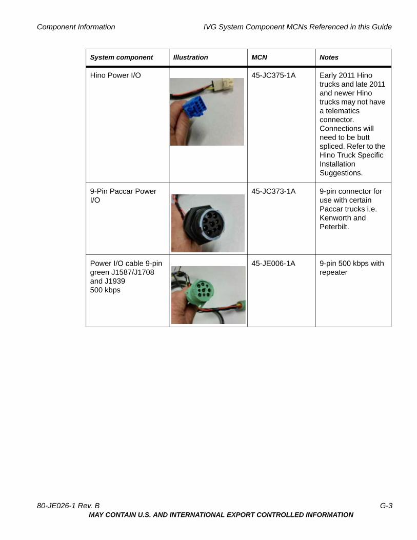
Component Information IVG System Component MCNs Referenced in this Guide
Hino Power I/O 45-JC375-1A Early 2011 Hino trucks and late 2011 and newer Hino trucks may not have a telematics connector. Connections will need to be butt spliced. Refer to the Hino Truck Specific Installation Suggestions.
9-Pin Paccar Power I/O
45-JC373-1A 9-pin connector for use with certain Paccar trucks i.e. Kenworth and Peterbilt.
Power I/O cable 9-pin green J1587/J1708 and J1939 500 kbps
45-JE006-1A 9-pin 500 kbps with repeater
System component Illustration MCN Notes
80-JE026-1 Rev. B G-3MAY CONTAIN U.S. AND INTERNATIONAL EXPORT CONTROLLED INFORMATION
IVG System Component MCNs Referenced in this Guide Component Information
G-4 80-JE026-1 Rev. BMAY CONTAIN U.S. AND INTERNATIONAL EXPORT CONTROLLED INFORMATION

HInstallation Form
Installation Form
Installation Work Order Details (IVG)
I find the service rendered and materials installed in connection with the above mentioned work to have been completed in a satisfactory manner.
Driver/Customer Signature: _________________________________________ Date: ____________________
______________ _____________
Active High________ Active Low (relay required)
80-JE026-1 Rev. B H-1MAY CONTAIN U.S. AND INTERNATIONAL EXPORT CONTROLLED INFORMATION
Installation Form Installation Form
H-2 80-JE026-1 Rev. BMAY CONTAIN U.S. AND INTERNATIONAL EXPORT CONTROLLED INFORMATION
RF Exposure Information (SAR)
This device meets the government's requirements for exposure to radio waves. This device is designed and manufactured to not exceed the emission limits for exposure to radio frequency (RF) energy set by the Federal Communications Commission (FCC) of the United States Government and Industry Canada (IC) of Canada. For optimal device performance and so that human exposure to RF energy does not exceed the FCC and IC guidelines, always follow these instructions and precautions: Orient the device in landscape mode with the cellular antenna (located at the top right corner of the device) away from your body or other objects.
The exposure standard employs a unit of measurement known as the Specific Absorption Rate, or SAR. The SAR limit set by the FCC is 1.6W/kg(1g) for body exposure and 4.0W/kg(10g) for extremity exposure. Tests for SAR are conducted using standard operating positions accepted by the FCC/IC with the EUT transmitting at the specified power level in different channels. Although SAR is determined at the highest certified power level in each frequency band, the actual SAR level of the device while in operation can be well below the maximum value because device adjusts its cellular transmitting power based, in part, on proximity to the wireless network.
In general, the closer you are to a cellular base station, the lower the cellular transmitting power level. The highest SAR value for the device as reported to the FCC is 1.26 W/kg(1g) when placed next to the body and 0.68 W/kg(10g) when exposed to extremities.
The device was tested according to measurement standards and procedures specified in FCC OET Bulletin 65, Supplement C (Edition 01-01) and Canada RSS 102. The FCC/IC has granted an Equipment Authorization for this device with all reported SAR levels evaluated as in compliance with the defined RF exposure guidelines. SAR information on this device is on file with the FCC and can be found under the Display Grant section ofwww.fcc.gov/oet/ea/fccid and searching on FCC ID: 2AE8ZIVG.
I
80-JE026-1 Rev. B I-1MAY CONTAIN U.S. AND INTERNATIONAL EXPORT CONTROLLED INFORMATION

I-2 80-JE026-1 Rev. BMAY CONTAIN U.S. AND INTERNATIONAL EXPORT CONTROLLED INFORMATION