Embed Size (px)
Citation preview

J LOGOSCREEN ntPaperless Recorder
with TFT display andCompactFlash card
B 70.6580.4Installation Instructions
08.06/00453822


Contents
1 Introduction 5
1.1 Preface .......................................................................................................... 5
1.2 Arrangement of the documentation ........................................................... 6
1.3 Typographical conventions ......................................................................... 8
2 Identifying the instrument version 9
2.1 Nameplate ..................................................................................................... 9
2.2 Type designation ........................................................................................ 10
2.3 Standard accessories ................................................................................ 11
2.4 Accessories ................................................................................................ 11
3 Installation 13
3.1 Installation site and climatic conditions .................................................. 13
3.2 Mounting ..................................................................................................... 13
4 Electrical connection 15
4.1 Installation notes ........................................................................................ 15
4.2 Procedure .................................................................................................... 16
4.3 Overview of the electrical isolation .......................................................... 17
4.4 Connection diagram .................................................................................. 18
5 Functional test 23
6 Technical data 25
7 Glossary 29

Contents

1 Introduction
1.1 PrefacePlease read these Operating Instructions before commissioning theinstrument. Keep the manual in a place that is accessible to all users at alltimes.
Please assist us to improve this operating manual, where necessary.
Your comments will be appreciated.
Phone: +49 661 6003-0Fax: +49 661 6003-607e-mail: [email protected]
HIf any difficulties should arise during commissioning, you are askednot to carry out any manipulations that could endanger your rightsunder the instrument warranty!
Please contact the nearest subsidiary or the head office in such acase.
EWhen returning modules, assemblies or components, theregulations of EN 61340-5-1 and EN 61340-5-2 “Protection ofelectronic devices from electrostatic phenomena” must beobserved. Use only the appropriate ESD packaging for transport.
Please note that we cannot accept any liability for damage causedby ESD.
ESD=electrostatic discharge
B
5

1 Introduction
1.2 Arrangement of the documentationThe documentation for this instrument is addressed to equipmentmanufacturers (OEMs) and users with appropriate technical expertise. Itconsists of the following parts:
Instrument documentation in printed form
B 70.6580.1 Operating Instructions
The operating instructions are an extract from the operating manual and coverthe basic operation of the paperless recorder.
B 70.6580.4 Installation Instructions
The installation instructions describe the installation of the recorder and theconnection of the supply and signal cables. The instructions also contain a listof the technical data.
Instrument documentation in the form of PDF files
The “Instrument documentation in the form of PDF files” is on the CD that isincluded in the delivery.
B 70.6580.0 Operating Manual
It contains information about commissioning, operation, parameterization andconfiguration on the instrument.
B 70.6580.1 Operating Instructions
The operating instructions are an extract from the operating manual and coverthe basic operation of the paperless recorder.
B 70.6580.2.0 Interface Description (serial interfaces)
This provides information on the communication (RS232/RS485) withsupervisory systems.
Interface Description (Ethernet interface)
This provides information on the connection of a paperless recorder to acompany-internal network. This description is integrated into B 70.6580.2.0.
B 70.6580.2.3 Interface Description (PROFIBUS-DP interface)
This provides information on the connection of a paperless recorder to aPROFIBUS-DP system.
6

1 Introduction
B 70.6580.4 Installation Instructions
The installation instructions describe the installation of the recorder and theconnection of the supply and signal cables. The instructions also contain a listof the technical data.
B 70.6580.6 Setup Program
The manual describes the function of the setup program. The setup program isavailable as an option.
T 70.6580 Data Sheet
The data sheet contains general information, the order details and thetechnical data.
B 70.9701.0 PC Evaluation software (PCA3000)
The operating manual describes the operation and the features of the PCevaluation software.
PCA3000 serves to visualize and evaluate process data (measurement data,batch data, messages ...). The process data can be read in via theCompactFlash memory card, or made available through the PCC software.
B 70.9702.0 PCA Communications software (PCC)
The operating manual describes the operation and the features of the PCACommunications software.
PCC is responsible for the data transfer from the recorder to a PC, or to anetwork.
HAll documents are available for downloading at www.jumo.net
7

1 Introduction
1.3 Typographical conventions
Warning signs
The signs for Danger and Caution are used in this manual under the followingconditions:
V
Danger
This symbol is used when there may be danger to personnel if theinstructions are ignored or not followed correctly!
ACaution
This symbol is used when there may be damage to equipment or data if theinstructions are ignored or not followed correctly!
E
Caution
This symbol is used where special care is required when handlingcomponents liable to damage through electrostatic discharge.
Note signs
HNote
This symbol is used when your special attention is drawn to a remark.
vReference
This symbol refers to further information in other manuals, chapters orsections.
abc1Footnote
Footnotes are remarks that refer to specific points in the text. Footnotesconsist of two parts:
A marker in the text, and the footnote text.
The markers in the text are arranged as continuous superscript numbers.
h
Action instruction
This symbol indicates that an action to be performed is described.
The individual steps are marked by this asterisk, e.g.
h Rotate control knob
h Press control knob
8

2 Identifying the instrument version
2.1 Nameplate
Identification
Position The nameplate is glued onto the paperless recorder.
Contents It contains important information, such as:
Type Please check the type supplied against your order document. Refer toChapter 2.2 “Type designation” for identification of the type.
VARTN The Sales No. provides an unambiguous definition of an article from thecatalog. It is used in communication between the sales department and thecustomer.
F-Nr The serial number (F-Nr.) indicates the production date (year/week). Thefigures concerned are in positions 12, 13, 14, 15.
Example:
F-Nr 0022969000005510006
This shows that the paperless recorder was manufactured in 2005, week 51.
Description Designation on the nameplate
Example
Device type Typ 706580/18-321-33/020Sales No. VARTN 70/00xxxxxxSerial No. F-Nr 0022969000005510006Supply voltage 110 — 240V AC
+10/-15%, 48 — 63Hz
9

2 Identifying the instrument version
2.2 Type designationBasic type
706580/Paperless recorder with Ethernet, Setup and RS232/RS485 interface andRS232 interface (to connect a barcode reader) and one relay
Basic type extensionsSoftware
0 No software package
1With software package (setup program, PC Evaluation software PCA3000,PCA Communications software PCC)
Language for instrument texts8 Factory setting (English/German)
9 Set to customer specification
1 2 3 Module slotsSlot 1 (bottom)
0 not used
2 3 analog inputs and 8 binary inputs/outputs
3 6 analog inputs
Slot 2 (middle)0 not used
2 3 analog inputs and 8 binary inputs/outputs
3 6 analog inputs
Slot 3 (top)0 not used
1 6 relay outputs
2 3 analog inputs and 8 binary inputs/outputs
3 6 analog inputs
Supply33 100 — 240V AC +10/-15%, 48 — 63Hz
25 20—30V AC/DC, 48 — 63Hz (under development)
Extra codes020 Lithium battery for memory buffering
021 Storage capacitor (instead of extra code 020)
260 Math and logic module
267 Profibus-DP interface (under development)
350 Universal carrying case TG-35
706580/ - - / ,...1
1. List extra codes in sequence, separated by commas.
(Order code)
706580/ 1 8 - 3 2 1 - 33 / 020 (Order example)
10
2 Identifying the instrument version
2.3 Standard accessories- 1 Installation Instructions B 70.6580.4
- 1 Operating Instructions B 70.6580.1
- 4 mounting brackets
- 1 panel seal
- 1 CD with detailed operating instructions and supplementary documentation (see Chapter 1.2 “Arrangement of the documentation”)
2.4 Accessories- Setup program
Sales No. 70/00468991
- PC Evaluation software (PCA3000)Sales No. 70/00431882
- PCA Communications software (PCC)Sales No. 70/00431879
- PC interface with TTL/RS232 converter and adapter (socket)Sales No. 70/00350260
- PC interface USB/TTL converter with adapter (socket) and adapter (pins)Sales No. 70/00456352
11

2 Identifying the instrument version
12

3 Installation
3.1 Installation site and climatic conditionsThe installation site should be as free as possible from vibration.Electromagnetic fields, such as those caused by motors, transformers etc.should be avoided as far as possible.
The ambient temperature at the site can be 0 to 50°C, at a relative humidity of≤75%, no condensation.
v Chapter 4.1 “Installation notes”
3.2 Mounting
Views
Panel cut-out
10 144
144
192
21
13

3 Installation
Mountingin a panel
h Fit panel seal (IP65 seal).
h Insert the paperless recorder from the front into the panel cut-out.
h From behind the panel, hook the four mounting brackets into the grooves on the sides of the housing. The flat faces of the mounting brackets must lie against the housing.
h Push the mounting brackets up against the back of the panel and tighten them evenly.
Panel seal
14

4 Electrical connection
4.1 Installation notes
k The choice of cable, the installation and the electrical connection mustconform to the requirements of VDE 0100 “Regulations on theInstallation of Power Circuits with Nominal Voltages below 1000V” or theappropriate local regulations.
k Work inside the instrument must only be carried out to the extentdescribed and, like the electrical connection, only by qualified personnel.
k The instrument must be disconnected on both poles from the electricalsupply if contact with live parts is possible while work is carried out.
k Electromagnetic compatibility (EMC) conforms to the standards andregulations cited in the technical data.
v Chapter 6 “Technical data”
k Run input, output and supply cables separately and not parallel to oneanother.
k All input and output cables without connection to the mains supply mustbe arranged as twisted and screened cables. Earth the screen on theinstrument side to the earth potential.
k Earth the instrument at the PE terminal to the protective earth conductor.This cable must have the same cross-section as that used for the supplycables. Earthing cables must be wired in a star configuration to acommon earth point that is connected to the protective earth conductorof the electrical supply. Do not loop earthing cables, i.e. do not run themfrom one instrument to another.
k Do not connect any additional loads to the supply terminals of theinstrument.
k The device is not suitable for use in areas with an explosion hazard (Exareas).
k Inductive loads close to the instrument, such as contactors or solenoidvalves, should have RC modules fitted for interference suppression.
k The supply to the instrument must be provided with additional fusing.Depending on the supply voltage, the following fuse values apply:
20 — 30V AC/DC, 48 — 63Hz : fuse 2A slow-blow
100 — 240V AC +10/-15%, 48 — 63Hz : fuse 1.6A slow-blow
An instrument fuse is already built into the device itself:
20 — 30V AC/DC, 48 — 63Hz : fuse 1.6A slow-blow
100 — 240V AC +10/-15%, 48 — 63Hz : fuse 1.25A slow-blow
15

4 Electrical connection
4.2 Procedureh Make the electrical connection as per Chapter 4.4 “Connection diagram”.
h Apply strain relief for the connecting cables, if necessary.
Instrumentvariant 1
Instrumentvariant 2
Module slot 3 (top)
Relay card}Module slot 2 (middle)
6 analog channels or 3 analog channels and 8 binary inputs/outputs
}Module slot 1 (bottom)
6 analog channels or 3 analog channels and 8 binary inputs/outputs
}
13
21 22 23 31 32 33 41 42 43 51 52 53 61 62 63 71 72 73
1 2 3 4
10 11 12
1 2 3 4 5 6
1211
987
B12
B 9
B10
B11
B13
B14
B15
B16
B4
B1
B2
B3
B5
B6
B7
B8 ++
+
U U
+ - -
- -
in outU
Uout
U
Uin
3 34 41 12 2
1 2 3 4 1 2 3 4 1 2 3 4 1 2 3 4 1 2 3 4 1 2 3 4
1 2 3 4 1 2 3 4 1 2 3 4
PENL1
(L+) (L-)
4.3.2.
1.
11.
9.
10.
8.
7.
5.
6.
14.
Connector number
13 14 15 16 17 18
4321
B20
B17
B18
B19
B21
B22
B23
B24
B12
B 9
B10
B11
B13
B14
B15
B16
B4B1
B2
B3
B5
B6
B7
B8 ++
U U
U
+ +
U
U
++
U
- -
- -
- -
in out
in out
in out
12 1311
1 2 3 4 1 2 3 4 1 2 3 4987
1 2 3 410 11
1 2 3 4 1 2 3 412
1 2 3 4 1 2 3 4 121
2 3 43
1 2 3 4 1 2 3 4 154
2 3 46
1 12 23 34 4 1 2 3 4 1 12 23 34 4
PENL1
(L+) (L-)11
12. 13.
4.3.2.
1.
11.
9.
10.
8.
7.
5.
6.
}Module slot 2 (middle)
6 analog channels or 3 analog channels and 8 binary inputs/outputs
}Module slot 1 (bottom)
6 analog channels or 3 analog channels and 8 binary inputs/outputs
}
Connector number
Module slot 3 (top)
6 analog channels or 3 analog channels and 8 binary inputs/outputs
16

4 Electrical connection
Connector summary
4.3 Overview of the electrical isolation
Connector/slot Function
1 Relay output
2 RS232 for barcode reader
3 PROFIBUS-DP
4 Supply voltage
5 Setup interface
6 Ethernet
7 RS232 and RS485
8 Analog input
9 Analog input or binary inputs/outputs
10 Analog input
11 Analog input or binary inputs/outputs
12 Analog input
13 Analog input or binary inputs/outputs
14 Relay card (for instrument variant 1)
17

4 Electrical connection
4.4 Connection diagram
Back panel v Chapter 4.2 “Procedure”
Connections
VThe electrical connection must onlybe carried out by specialist personnel.
Terminal assignment Connector Diagram
Supplyvoltage
Supply voltage
as on nameplate
Connector 4L1 (L+)N (L-)PE
Analog inputs ThermocoupleConnectors 8 to 11(input 1—12) for instrumentvariant 1
or
connectors8 to 13(input 1—18) for instrument variant 2
RTD2-wire circuit
RTD3-wire circuit
RTD4-wire circuit
Resistance transmitter
E = endS = sliderA = start
Potentiometer in2-wire circuit
Potentiometer in3-wire circuit
Potentiometer in4-wire circuit
13
21 22 23 31 32 33 41 42 43 51 52 53 61 62 63 71 72 73
1 2 3 4
10 11 12
1 2 3 4 5 6
1211
987
B12
B 9
B10
B11
B13
B14
B15
B16
B4
B1
B2
B3
B5
B6
B7
B8 ++
+
U U
+ - -
- -
in outU
Uout
U
Uin
3 34 41 12 2
1 2 3 4 1 2 3 4 1 2 3 4 1 2 3 4 1 2 3 4 1 2 3 4
1 2 3 4 1 2 3 4 1 2 3 4
PENL1
(L+) (L-)
1 2 3 4
10 11 12
1 2 3 4 5 6
987
3 34 41 12 2
1 2 3 4 1 2 3 4 1 2 3 4 1 2 3 4 1 2 3 4 1 2 3 4
1 2 3 4 1 2 3 4 1 2 3 4
21 3 4
+ –
21 3 4
�
21 3 4
�
21 3 4
�
21 3 4E S A
21 3 4
21 3 4
21 3 4
18

4 Electrical connection
Analog inputs Voltage input 0 — 1V Connectors 8 to 11(input 1—12) for instrument variant 1
or
connectors8 to 13(input 1—18) for instrument variant 2
Voltage input 0 — 10V
Current input
Terminal assignment Connector Diagram
13
21 22 23 31 32 33 41 42 43 51 52 53 61 62 63 71 72 73
1 2 3 4
10 11 12
1 2 3 4 5 6
1211
987
B12
B 9
B10
B11
B13
B14
B15
B16
B4
B1
B2
B3
B5
B6
B7
B8 ++
+
U U
+ - -
- -
in outU
Uout
U
Uin
3 34 41 12 2
1 2 3 4 1 2 3 4 1 2 3 4 1 2 3 4 1 2 3 4 1 2 3 4
1 2 3 4 1 2 3 4 1 2 3 4
PENL1
(L+) (L-)
1 2 3 4
10 11 12
1 2 3 4 5 6
987
3 34 41 12 2
1 2 3 4 1 2 3 4 1 2 3 4 1 2 3 4 1 2 3 4 1 2 3 4
1 2 3 4 1 2 3 4 1 2 3 4
19

4 Electrical connection
-ut
Binary inputs/outputs H The configuration in the instrument or in the setup program
defines whether it is a binary input or binary output.
B1 … B8
voltage-controlledLOW = -3 to +5V DCHIGH = 12 to 30V DC
B1 Binary input/output 1B2 Binary input/output 2B3 Binary input/output 3B4 Binary input/output 4B5 Binary input/output 5B6 Binary input/output 6B7 Binary input/output 7B8 Binary input/output 8
Uin+ external auxiliary supply(non-stabilized)
Uin- ground for externalauxiliary supply
Uout+ +24V auxiliary supplyUout- ground for
auxiliary supply
Connector 9
only for modules with 3 analoginputs
Example: Connecting a load to binary output 4 (B4) and a solid-staterelay to binaryoutput 3 (B3) requiresan external auxiliary supply.
Diagram of theconnector:
B9 … B16
voltage-controlledLOW = -3 to +5V DCHIGH = 12 to 30V DC
B9 Binary input/output 9B10 Binary input/output 10B11 Binary input/output 11B12 Binary input/output 12B13 Binary input/output 13B14 Binary input/output 14B15 Binary input/output 15B16 Binary input/output 16
Uin+ external auxiliary supplyUin- ground for external
auxiliary supplyUout+ +24V auxiliary supplyUout- ground for
auxiliary supply
11
only for modules with 3 analoginputs
Example: Binary input 12 (B12) is operated from the internal power supply.
Diagram of theconnector:
Terminal assignment Connector Diagram
B1
B2
B3
B4
B5
B6
B7
B8
Uin
+
Uin
-
Uout+
Uout-
B10
B11
B12
B13
B14
B15
B16
+ - +B9 Uin Uo
B9
B10
B11
B12
B13
B14
B15
B16
Uin
+
Uin
-
Uout+
Uout-
20

4 Electrical connection
-ut
Binärein-/-ausgänge
B17 … B24
voltage-controlledLOW = -3 to +5V DCHIGH = 12 to 30V DC
B17 Binary input/output 17B18 Binary input/output 18B19 Binary input/output 19B20 Binary input/output 20B21 Binary input/output 21B22 Binary input/output 22B23 Binary input/output 23B24 Binary input/output 24
Uin+ external auxiliary supplyUin- ground for external
auxiliary supplyUout+ +24V auxiliary supplyUout- ground for
auxiliary supply
Connector 13
only for instrument variant 2 and on modules with 3 analoginputs
Example: Binary input 20 (B20) is operated from the internal power supply.
Diagram of theconnector:
Relay outputs Relay 1 - alarmchangeover (SPDT)
Connector 1
Relay 2changeover (SPDT)
Connector 14
only for instrument variant 1
Relay 3changeover (SPDT)
Relay 4changeover (SPDT)
Relay 5changeover (SPDT)
Relay 6changeover (SPDT)
Relay 7changeover (SPDT)
Terminal assignment Connector Diagram
B18
B19
B20
B21
B22
B23
B24
+ - +B17 Uin Uo
B17
B18
B19
B20
B21
B22
B23
B24
Uin
+
Uin
-
Uout+
Uout-
1312 11
13
21 22 23 31 32 33 41 42 43 51 52 53 61 62 63 71 72 73
1 2 3 4
10 11 12
1 2 3 4 5 6
1211
987
B12
B 9
B10
B11
B13
B14
B15
B16
B4
B1
B2
B3
B5
B6
B7
B8 ++
+
U U
+ - -
- -
in outU
Uout
U
Uin
3 34 41 12 2
1 2 3 4 1 2 3 4 1 2 3 4 1 2 3 4 1 2 3 4 1 2 3 4
1 2 3 4 1 2 3 4 1 2 3 4
PENL1
(L+) (L-)
21 22 23 31 32 33 41 42 43 51 52 53 61 62 63 71 72 73
2322 21
3332 31
4342 41
5352 51
6362 61
7372 71
21

4 Electrical connection
Interfaces RS232C for barcode reader9-pin SUB-D socket connector
2 RxD receive data3 TxD transmit data5 GND ground
Connector 2
PROFIBUS-DP9-pin SUB-D socket connector
(extra code)
3 RxD/TxD-P B conductorReceive/transmit data positive
5 DGND Data transmission ground
6 VP supply voltage positive8 RxD/TxD-N A conductor
Receive/transmit data negative
Connector 3
Setup interface
The recorder also has a setup interface on the front panel, connected in parallel. The two interfaces cannot both be operated at the same time.
Connector 5
EthernetRJ45 socket connector
1 TX+ transmit data +2 TX- transmit data -3 RX+ receive data +6 RX+ receive data -
Connector 6
RS232C9-pin SUB-D socket connector
(switchable to RS485)
2 RxD receive data3 TxD transmit data5 GND ground
Connector 7
RS4859-pin SUB-D socket connector
(switchable to RS232)
3 TxD+/RxD+ Transmit/receive data +
5 GND ground8 TxD-/RxD-
Transmit/receive data -
Connector 7
Terminal assignment Connector Diagram
21 3 4 5
6 7 8 9
21 3 4 5
6 7 8 9
81
2 1345
6789
2 1345
6789
22

5 Functional test
After the paperless recorder has been installed and wired up, it can becommissioned. After applying or switching on the supply voltage, the start-upscreen will appear for a short time.
Start-up screen
The visualization will start automatically after the initialization phase.
Visualization
The paperless recorder is now in the recording phase.
Further steps
AThe recorder can be configured by an authorized person, either byusing the control knob (rotating and pressing) or with the help ofthe PC setup program.
Further information about configuration can be found in theOperating Manual B 70.6580.0.
Finally, make another check that the connection, configuration andfunction of the recorder are all correct.
23

5 Functional test
24

6 Technical data
Analog inputs
Thermocouple
Resistance thermometers
Designation Type Standard Meas. range Accuracy1
Fe-Con L DIN 43 710Fe-Con J EN 60 584Cu-Con U DIN 43 710Cu-Con T EN 60 584NiCr-Ni K EN 60 584NiCr-Con E EN 60 584NiCrSi-NiSi N EN 60 584Pt10Rh-Pt S EN 60 584Pt13Rh-Pt R EN 60 584Pt30Rh-Pt6Rh B EN 60 584W3Re/W25Re DW5Re/W26Re CW3Re/W26ReChromel-alumel GOST R 8.585-2001Chromel-copel GOST R 8.585-2001PLII (Platinel II)
-200 to +900°C-200 to +1200°C-200 to +600°C-270 to +400°C-200 to +1372°C-200 to +1000°C-100 to +1300°C
0 to 1768°C0 to 1768°C0 to 1820°C0 to 2495°C0 to 2320°C0 to 2400°C
-200 to +1372°C-200 to +800°C
0 to 1395°C
±0.1%±0.1% from -100°C±0.1% from -150°C±0.1% from -150°C±0.1% from -80°C±0.1% from -80°C±0.1% from -80°C±0.15% ±0.15% ±0.15% from 400°C±0.15% from 500°C±0.15% from 500°C±0.15% from 500°C±0.1% from -80°C±0.15% from -80°C±0.15%
Shortest span Type L, J, U, T, K, E, N, chromel-alumel, PLII: 100°CType S, R, B, D, C, W3Re/W26Re, chromel-copel: 500°C
Range start/end freely programmable within the limits, in 0.1°C steps
Cold junction Pt100 internal or thermostat external constant
Cold junction accuracy (internal) ± 1°C
Cold junction temperature (external) -50 to +150°C adjustable
Sampling cycle channel 1 — 18: 125msec in total
Input filter 2nd order digital filter; filter constant adjustable from 0 to 10.0sec
Electrical isolation see “Electrical data” on page 5 and “Overview of the electrical isolation” on page 15
Resolution >14 bit
Features also programmable in °F1. The linearization accuracy refers to the maximum measuring range. The linearization accuracy is reduced with short spans.
Designation Standard Connection circuit Meas. range Accuracy1 Meas. curr.
Pt100 EN 60 751(TC = 3.85*10-3 1/°C)
2/3-wire2/3-wire4-wire
-200 to +100°C-200 to +850°C-200 to +850°C
±0.5°C±0.8°C±0.5°C
≈ 250μA≈ 250μA≈ 250μA
Pt100 JIS 1604(TC = 3.917*10-3 1/°C)
2/3-wire2/3-wire4-wire
-200 to +100°C-200 to +650°C-200 to +650°C
±0.5°C±0.8°C±0.5°C
≈ 250μA≈ 250μA≈ 250μA
Pt100 GOST 6651-94 A.1(TC = 3.91*10-3 1/°C)
2/3-wire, 4-wire2/3-wire, 4-wire
-200 to +100°C-200 to +850°C
±0.5°C±0.8°C
≈ 250μA≈ 250μA
Pt500 EN 60 751(TC = 3.85*10-3 1/°C)
2/3-wire, 4-wire2/3-wire, 4-wire
-200 to +100°C-200 to +850°C
±0.5°C±0.9°C
≈ 100μA≈ 100μA
Pt1000 EN 60 751(TC = 3.85*10-3 1/°C)
2/3-wire2/3-wire4-wire
-200 to +100°C-200 to +850°C-200 to +850°C
±0.5°C±0.8°C±0.5°C
≈ 100μA≈ 100μA≈ 100μA
Ni 100 DIN 43 760(TC = 6.18*10-3 1/°C)
2/3-wire, 4-wire -60 to +180°C ±0.4°C ≈ 250μA
Pt50 ST RGW 1057 1985(TC = 3.91*10-3 1/°C)
2/3-wire2/3-wire4-wire4-wire
-200 to +100°C-200 to +1100°C-200 to +100°C-200 to +1100°C
±0.5°C±0.9°C±0.5°C±0.6°C
≈ 250μA≈ 250μA≈ 250μA≈ 250μA
Cu 50 (TC = 4.26*10-3 1/°C) 2/3-wire2/3-wire4-wire4-wire
-50 to +100°C-50 to +200°C-50 to +100°C-50 to +200°C
±0.5°C±0.9°C±0.5°C±0.7°C
≈ 250μA≈ 250μA≈ 250μA≈ 250μA
25

6 Technical data
Resistance transmitter and potentiometer
Input for DC voltage, DC current
Cu 100 GOST 6651-94 A.1(TC = 4.26*10-3 1/°C)
2/3-wire2/3-wire4-wire4-wire
-50 to +100°C-50 to +200°C-50 to +100°C-50 to +200°C
±0.5°C±0.9°C±0.5°C±0.6°C
≈ 250μA≈ 250μA≈ 250μA≈ 250μA
Connection circuit 2-, 3-, or 4-wire circuit
Shortest span 15°C
Sensor lead resistance max. 30 Ω per conductor for 3-wire/4-wire circuitmax. 10Ω per conductor for 2-wire circuit
Range start/end freely programmable within the limits in 0.1°C steps
Sampling cycle channel 1 — 18: 125msec in total
Input filter 2nd order digital filter; filter constant adjustable from 0 to 10sec
Electrical isolation see “Electrical data” on page 5 and “Overview of the electrical isolation” on page 15
Resolution > 14bit
Features also programmable in °F1. The linearization accuracy refers to the maximum measuring range. The linearization accuracy is reduced with short spans.
Designation Meas. range Accuracy1 Measuring current
Resistance transmitter up to 4000Ω ±4Ω ≈ 100μA
Potentiometer < 400Ω≥ 400Ω to 4000Ω
±400 mΩ±4Ω
≈ 100μA≈ 250μA
Connection circuit resistance transmitter: 3-wire circuitpotentiometer: 2-/3-/4-wire circuit
Shortest span 60ΩSensor lead resistance max. 30Ω per conductor for 4-wire circuit
max. 10 Ω per conductor for 2-/3-wire circuit
Resistance values freely programmable within the limits, in 0.1Ω steps
Sampling cycle channel 1 — 18: 125msec in total
Input filter 2nd order digital filter; filter constant adjustable from 0 to 10.0sec
Electrical isolation see “Electrical data” on page 5 and “Overview of the electrical isolation” on page 15
Resolution > 14bit1. The linearization accuracy refers to the maximum measuring range. The linearization accuracy is reduced with short spans.
Basic range Accuracy1 Input resistance
-12 to +112mV-10 to +210mV
-1.5 to +11.5V-0.12 to +1.12V-1.2 to +1.2V-11 to +12V
±100μV±240μV
±6mV±1mV±2mV
±12mV
RIN ≥ 1 MΩRIN ≥ 470 kΩRIN ≥ 470 kΩRIN ≥ 470 kΩRIN ≥ 470 kΩRIN ≥ 470 kΩ
Shortest span 5mV
Range start/end freely programmable within the limits in 0.01 mV steps
-1.3 to +22mA-22 to +22mA
±20μA±44μA
burden voltage ≤ 3Vburden voltage ≤ 3V
Shortest span 0.5mA
Range start/end freely programmable within the limits in 0.01 mA steps
Overrange/underrange according to NAMUR NE 43
Sampling cycle channel 1 — 18: 125msec in total
Input filter 2nd order digital filter; filter constant adjustable from 0 to 10.0sec
Electrical isolation see “Electrical data” on page 5 and “Overview of the electrical isolation” on page 15
Resolution > 14bit1. The linearization accuracy refers to the maximum measuring range. The linearization accuracy is reduced with short spans.
Designation Standard Connection circuit Meas. range Accuracy1 Meas. curr.
26

6 Technical data
Transducer short circuit/break
Binary inputs/outputs (option)
Outputs
Interfaces
Screen
Short-circuit1 Break1
Thermocouple not detected detectedResistance thermometer detected detectedResistance transmitter not detected detectedPotentiometer not detected detectedVoltage ≤ ± 210mV not detected detectedVoltage > ± 210mV not detected not detectedCurrent not detected not detected1. Programmable reaction of device, e.g. triggering alarm
Input or output configurable as input or outputNumber 8, 16 or 24, depending on the device version,
to DIN VDE 0411, Part 500; max. 25Hz, max. 32VInput
- level logic “0”: -3 to +5V (input current max. ±1mA),logic “1”: 12 — 30V (2.5mA ≤ input current ≤ 5mA)
- pulse width min. 300msec- sampling cycle (for recording) 1Hz
High-speed input the first two binary inputs of each module (B1, B2, B9, B10, B17, B18),if the module is not fitted with relays or 6 analog inputs
- task count function, e.g. for flow measurement- pulse width min. 300μs- sampling cycle 10kHz
Output- type open-collector output, switches relative to positive voltage- level logic “0”: transistor is inhibited
(max. permissible voltage across switching transistor ≤ 30V, max. leakage current 0.1 mA)logic “1”: transistor is switched on
(max. voltage across switching transistor ≤1.6V, max. current 50mA)- sampling cycle at least 1sec (1Hz)
1 relay (ex-factory) changeover (SPDT), 3A, 230V AC1
6 relays (option) changeover (SPDT), 3A, 230V AC1,2
1. with resistive load. 2. It is not permissible to mix SELV circuits and supply circuits.
RS232/RS485 (connector 7)- protocol- baud rate- modem- connector- external inputs
Qty. 1, switchable between RS232 and RS485MODbus master, MODbus slave and barcode reader
9600, 19200, 38400can be connected
SUB-Dvia the MODbus master/salve function, 24 analog and 24 binary
RS232 for barcode reader (connector 2)- protocol- baud rate- connector- external inputs
Qty. 1MODbus master, MODbus slave and barcode reader
9600, 19200, 38400SUB-D
via the MODbus master/salve function, 24 analog and 24 binaryEthernet (connector 6)
- quantity- protocols- baud rate- connector- data format
max. 1TCP, IP, HTTP, DHCP, SMTP, MODbusTCP
10Mbits/sec, 100Mbits/secRJ45HTML
Resolution / size 320 x 240 pixels / 5.5"Type / number of colors TFT color screen / 256 colorsScreen refresh rate > 150HzBrightness setting adjustable on instrumentScreen saver (switch-off) through waiting time or control signal
27
6 Technical data
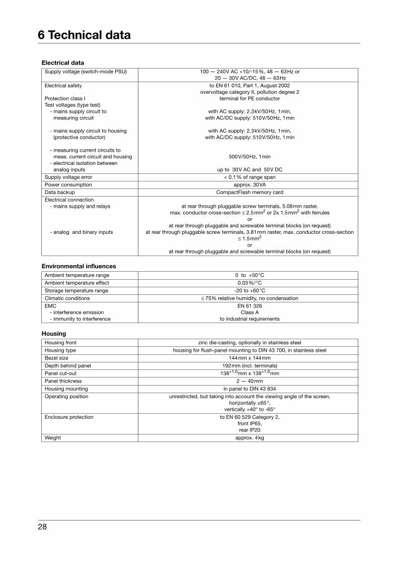
Electrical data
Environmental influences
Housing
Supply voltage (switch-mode PSU) 100 — 240V AC +10/-15%, 48 — 63Hz or 20 — 30V AC/DC, 48 — 63Hz
Electrical safety
Protection class ITest voltages (type test)
- mains supply circuit to measuring circuit
- mains supply circuit to housing(protective conductor)
- measuring current circuits to meas. current circuit and housing
- electrical isolation betweenanalog inputs
to EN 61 010, Part 1, August 2002overvoltage category II, pollution degree 2
terminal for PE conductor
with AC supply: 2.3kV/50Hz, 1min,with AC/DC supply: 510V/50Hz, 1min
with AC supply: 2.3kV/50Hz, 1min,with AC/DC supply: 510V/50Hz, 1min
500V/50Hz, 1min
up to 30V AC and 50V DCSupply voltage error < 0.1% of range spanPower consumption approx. 30VAData backup CompactFlash memory cardElectrical connection
- mains supply and relays
- analog and binary inputs
at rear through pluggable screw terminals, 5.08mm raster,max. conductor cross-section ≤ 2.5mm2 or 2x 1.5mm2 with ferrules
orat rear through pluggable and screwable terminal blocks (on request)
at rear through pluggable screw terminals, 3.81mm raster, max. conductor cross-section ≤ 1.5mm2
orat rear through pluggable and screwable terminal blocks (on request)
Ambient temperature range 0 to +50°C
Ambient temperature effect 0.03%/°C
Storage temperature range -20 to +60°C
Climatic conditions ≤ 75% relative humidity, no condensation
EMC- interference emission- immunity to interference
EN 61 326Class A
to industrial requirements
Housing front zinc die-casting, optionally in stainless steel
Housing type housing for flush-panel mounting to DIN 43 700, in stainless steel
Bezel size 144mm x 144mm
Depth behind panel 192mm (incl. terminals)
Panel cut-out 138+1.0mm x 138+1.0mm
Panel thickness 2 — 40mm
Housing mounting in panel to DIN 43 834
Operating position unrestricted, but taking into account the viewing angle of the screen,horizontally ±65°,
vertically +40° to -65°
Enclosure protection to EN 60 529 Category 2,front IP65,rear IP20
Weight approx. 4kg
28
7 Glossary
AAccessories 11
BBack panel 18
CClimatic conditions 13Commissioning 5CompactFlash 7Connection diagram 18
DDocumentation, arrangement of 6
EElectrical connection 15Electrostatic discharge (ESD) 5
FFunctional test 23
IInstallation 13Installation notes 15Installation site 13Instrument documentation in printed form 6Instrument documentation in the form of PDF files 6Instrument version, identification of 9Introduction 5
MMounting 13
NNameplate 9Nameplate, identification of 9Note signs 8
29

7 Glossary
PPanel mounting 14
RReturning 5
SStandard accessories 11Start-up screen 23
TTechnical data 25Type designation 10Typographical conventions 8
VViews 13Visualization level 23
WWarning signs 8Warranty 5
30


JUMO GmbH & Co. KGStreet address:Moltkestraße 13 - 3136039 Fulda, GermanyDelivery address:Mackenrodtstraße 1436039 Fulda, GermanyPostal address:36035 Fulda, GermanyPhone: +49 661 6003-0Fax: +49 661 6003-607e-mail: [email protected]: www.jumo.net
JUMO Instrument Co. Ltd.JUMO HouseTemple Bank, RiverwayHarlow, Essex CM20 2TT, UKPhone: +44 1279 635533Fax: +44 1279 635262e-mail: [email protected]: www.jumo.co.uk
JUMO Process Control, Inc.8 Technology BoulevardCanastota, NY 13032, USAPhone: 315-697-JUMO
1-800-554-JUMOFax: 315-697-5867e-mail: [email protected]: www.jumo.us