Embed Size (px)
Citation preview
Addendum No. 2 Page 1 of 3 2018 Bond Project: Building Entry Façade and Door Improvements for Lanier High School Jackson Public School District DDG Project No.: 19.003
DURRELL DESIGN GROUP, PLLC
500-G E. WOODROW WILSON AVENUE
JACKSON, MISSISSIPPI 39216
PHONE: 601.708.4788 FAX: 601.398.3960
2018 BOND PROJECT: FAÇADE AND DOOR IMPROVEMENTS FOR LANIER HIGH SCHOOL
JACKSON PUBLIC SCHOOL DISTRICT
JACKSON, MISSISSIPPI
November 3, 2020
TITLE SHEET 1 ADDENDUM 2 ATTACHMENTS 93 TOTAL NUMBER OF PAGES 96
Addendum No. 2 Page 2 of 3 2018 Bond Project: Building Entry Façade and Door Improvements for Lanier High School Jackson Public School District DDG Project No.: 19.003
THIS ADDENDUM, WHICH CONTAINS REVISIONS TO THE WORK CONTAINED IN THE ORIGINAL DRAWINGS AND SPECIFICATIONS DATED September 30, 2020 SHALL BECOME A PART OF SUCH DRAWINGS AND SPECIFICATIONS AS IF BOUND THEREIN, OTHER REQUIREMENTS OF DRAWINGS AND SPECIFICATIONS RELATING TO ITEMS INVOLVED SHALL REMAIN AS SPECIFIED.
THE ABOVE NAMED CONTRACT DOCUMENTS ARE HEREBY MODIFIED, CORRECTED AND/OR SUPPLEMENTED BY THIS ADDENDUM AS FOLLOWS:
PERTAINING TO THE SPECIFICATIONS:
Item 1: SECTION 00000. ADVERTISEMENT FOR BIDS
The Bid Opening will be modified from November 4, 2020 at 10AM to November 11, 2020 at
2PM.
Item 2: TABLE OF CONTENTS
A. ADD Section 08 41 00 Metal Frame Storefront.
B. DELETE wording that reads as “09 51 00 and REPLACE with “09 51 10”.
Item 3: Section 04 72 00 CAST STONE
DELETE PARAGRAPH 2.1A in its entirety and REPLACE with “A. Basis of Design
Manufacturer: Johnson County Form, Inc, Website www.jcfcompanies.com Email
Item 5: Section 05 52 00 HANDRAILS AND RAILING
DELETE Section in its entirety and REPLACE with Attached Section 05 52 00 – HANDRAILS
AND RAILINGS
Item 6: Section 08 71 00
A. Hardware Set #3 DELETE door #117
B. Hardware Set #9 DELETE door #118
C. CLARIFICATION: Door #117 and 118 are aluminum storefront system. See hardware
information in Section 08 41 00 Metal Frame Storefront
Item 7: Section 22 PLUMBING
DELETE Section 22 in its entirety and REPLACE with Attached Section 22.
Item 8: Section 23 HEATING, VENTILATING, AND AIR CONDITIONING (HVAC)
DELETE Section 23 in its entirety and REPLACE with Attached Section 24.
Addendum No. 2 Page 3 of 3 2018 Bond Project: Building Entry Façade and Door Improvements for Lanier High School Jackson Public School District DDG Project No.: 19.003
PERTAINING TO THE DRAWINGS:
Item 9: TITLE SHEET T101
DELETE the entire sheet and REPLACE with attached.
Item 10: CIVIL SHEETS C101, C201 AND C301
DELETE the entire sheet and REPLACE with attached.
Item 11: ARCHITECTURAL SHEETS A101-A702
DELETE the entire sheet and REPLACE with attached SHEET T101R AND SHEET A101R-
A702R.
Item 12: PLUMBING SHEETS P101-P103
DELETE the entire sheet and REPLACE with attached.
Item 13: HVAC SHEETS M101-M103
DELETE the entire sheet and REPLACE with attached.
Item 14: SHEET E101 ELECTRICAL SYMBOLS, LIGHTING SCHEDULE
DELETE the entire sheet and REPLACE with attached.
Item 15: SHEET E202 ELECTRICAL FLOOR PLANS ADMIN & OFFICES
DELETE the entire sheet and REPLACE with attached.
Item 16: SHEET E203 OUTDOOR SIGNAGE LIGHTING
ADD attached SHEET E203.
END OF ADDENDUM ITEMS
DDG Project No.: 19.003 HANDRAILS AND RAILINGS 055200- 1 2018 Bond Project: Lanier High School Jackson Public School District
SECTION 05 52 00
HANDRAILS AND RAILINGS
PART 1 GENERAL
1.01 SECTION INCLUDES A. Wall mounted handrails.
B. Stair railings and guardrails.
C. Free-standing railings at steps.
1.02 RELATED REQUIREMENTS
A. Section 03300 (03 3000) - Cast-in-Place Concrete: Placement of anchors in
concrete.
B. Section 04810 (04 2000) - Unit Masonry Assemblies: Placement of anchors in
masonry.
C. Section 09900 (09 9000)- Paints and Coatings: Paint finish.
1.03 REFERENCE STANDARDS
A. ASTM A53/A53M- Standard Specification for Pipe, Steel, Black and Hot-Dipped,
Zinc-Coated, Welded and Seamless; 2010.
B. ASTM A123/A123M - Standard Specification for Zinc (Hot-Dip Galvanized)
Coatings on Iron and Steel Products; 2009.
C. ASTM A500/A500M - Standard Specification for Cold-Formed Welded and
Seamless Carbon Steel Structural Tubing in Rounds and Shapes; 201Oa.
D. ASTM E935 - Standard Test Methods for Performance of Permanent Metal
Railing Systems and Rails for Buildings; 2000 (Reapproved 2006).
E. ASTM E985 - Standard Specification for Permanent Metal Railing Systems and
Rails for Buildings; 2000 (Reapproved 2006).
F. SSPC-Paint 20 - Zinc-Rich Primers (Type I, "Inorganic," and Type II, "Organic");
The Society for Protective Coatings; 2002 (Ed. 2004).
1.04 SUBMITTALS
A. See Section 01300 (01 3000) - Administrative Requirements, for submittal
procedures.
B. Shop Drawings: Indicate profiles, sizes, connection attachments, anchorage,
size and type of fasteners, and accessories.
C. Samples: Submit two, 12 inch long samples of handrail. Submit two samples of
elbow, Tee, wall bracket, and end stop.
DDG Project No.: 19.003 HANDRAILS AND RAILINGS 055200- 2 2018 Bond Project: Lanier High School Jackson Public School District
PART 2 P R O D U C TS
2.01 ACCEPTABLE MANUFACTURER
A. One Line Rail Design Model: ANDA by Efficient-Tec International, LLC, Phone:
1.866.356.4458, Email: [email protected] Website: www.eti-s3.com
B. See Section 01630 – Substitutions and Product Options
2.02 RAILINGS - GENERAL REQUIREMENTS
A. Design, f ab r i ca te , and t es t r a i l ing assemblies in accordance w i t h the
most stringent requirements of ASTM E985 and applicable local code.
B. Distributed Loads: Design r a i l i n g assembly, wall rails, and attachments to
resist distributed force of 75 pounds per linear foot applied to the top of the
assembly and in any direction, without damage or permanent set. Test in
accordance with ASTM E 935.
C. Allow for expansion and contraction of members and building movement without
damage to connections or members.
D. Dimensions: See drawings for configurations and heights.
1. Top Rails and Wall Rails: 1-1/2 inches diameter, round.
2. Intermediate Rails: 1-1/2 inches diameter, round.
3. Posts: 1-1/2 inches diameter, round.
E. Provide anchors and other components as required to attach to structure, made
of same materials as railing components unless otherwise indicated; where
exposed fasteners are unavoidable provide flush countersunk fasteners.
1. For anchorage to masonry, provide brackets to be embedded in masonry, for
welding anchors.
2. Posts: Provide adjustable flanged brackets.
F. Provide welding fittings to join lengths, seal open ends, and conceal exposed
mounting bolts and nuts, including but not limited to elbows, T-shapes, sp l i ce
connectors, flanges, escutcheons, and wall brackets.
2.03 MATERIAL
A. Material for Posts: 316 Stainless Steel B. Material for Hand Rail: 316 Stainless Steel C. Material for Cap Rail: 316 Stainless Steel
2.04 FABRICATION
A. Accurately form components to suit specific project conditions and for proper
connection to building structure.
B. Fit and shop assemble components in largest practical sizes for delivery to site.
C. Fabricate components with joints tightly fitted and secured. Provide spigots and
sleeves to accommodate site assembly and installation.
DDG Project No.: 19.003 HANDRAILS AND RAILINGS 055200- 3 2018 Bond Project: Lanier High School Jackson Public School District
D. Welded Joints:
1. Exterior Components: Continuously seal joined pieces by intermittent welds
and plastic filler. Drill condensate drainage holes at bottom of members at
locations that will not encourage water intrusion.
2. Interior Components: Continuously seal joined pieces by intermittent welds
and plastic filler.
3. Grind exposed joints flush and smooth with adjacent finish surface. Make
exposed joints butt tight, flush, and hairline. Ease exposed edges to small
uniform radius.
PART 3 EXECUTION
3.01 EXAMINATION
A. Verify that field conditions are acceptable and are ready to receive work.
3.02 PREPARATION
A. Clean and strip primed steel items to bare metal where site welding is required.
B. Supply items required to be embedded in masonry with setting templates, for
installation as work of other sections.
C. Apply one coat of bituminous paint to concealed aluminum surfaces that will be in
contact with cementitious or dissimilar materials.
3.03 INSTALLATION
A. Install in accordance with manufacturer's instructions.
B. Install components plumb and level, accurately fitted, free from distortion or
defects, with tight joints.
C. Anchor railings securely to structure.
D. Field weld anchors as indicated on drawings. Touch-up welds with primer. Grind
welds smooth.
3.04 TOLERANCES
A. Maximum Variation From Plumb: 1/4 inch per floor level, non-cumulative.
B. Maximum Offset From True Alignment: 1/4 inch.
C. Maximum Out-of-Position: 1/4 inch.
END OF SECTION
DDG Project No. 19.003 METAL-FRAMED STOREFRONTS 08 41 00 - 1 2018 Bond Project: Lanier High School
Jackson Public School
SECTION 08 41 00
METAL-FRAMED STOREFRONTS
PART 1 GENERAL
1.01 SECTION INCLUDES
A. Aluminum-framed storefront, with vision glass.
B. Aluminum doors and frames with door hardware.
C. Perimeter sealant.
D. Door hardware.
1.02 RELATED REQUIREMENTS
A. Section 05500 (055000) - Metal Fabrications: Steel attachment devices.
B. Section 07900 (079005) - Joint Sealers: Perimeter sealant and back-up materials.
C. Section 08800 (088000) - Glazing: Glass and glazing accessories.
1.03 REFERENCE STANDARDS
A. AAMA CW-10 - Care and Handling of Architectural Aluminum From Shop to Site; American Architectural Manufacturers Association; 2004.
B. AAMA 2604 - Voluntary Specification, Performance Requirements and Test Procedures for High Performance Organic Coatings on Aluminum Extrusions and Panels; 2005.
C. ASCE 7 - Minimum Design Loads for Buildings and Other Structures; American Society of Civil Engineers; 2010.
D. ASTM A36/A36M - Standard Specification for Carbon Structural Steel; 2008.
E. ASTM A123/A123M - Standard Specification for Zinc (Hot-Dip Galvanized) Coatings on Iron and Steel Products; 2009.
F. ASTM B221 - Standard Specification for Aluminum and Aluminum-Alloy Extruded Bars, Rods, Wire, Profiles, and Tubes; 2008.
G. ASTM B221M - Standard Specification for Aluminum and Aluminum-Alloy Extruded Bars, Rods, Wire, Profiles, and Tubes [Metric]; 2007.
1.04 ADMINISTRATIVE REQUIREMENTS
A. Coordinate with installation of other components that encompass enclosure.
B. Preinstallation Meeting: Conduct a preinstallation meeting one week before starting work of this section; require attendance by all affected installers.
1.05 SUBMITTALS
A. See Section 01300 - Administrative Requirements, for submittal procedures.
B. Product Data: Provide component dimensions, describe components within assembly, anchorage and fasteners, glass and infill, door hardware, internal drainage details.
DDG Project No. 19.003 METAL-FRAMED STOREFRONTS 08 41 00 - 2 2018 Bond Project: Lanier High School
Jackson Public School
C. Shop Drawings: Indicate system dimensions, framed opening requirements and tolerances, affected related Work, expansion and contraction joint location and details, and field welding required.
D. Samples: Submit two samples 12 x 12 inches in size illustrating finished aluminum surface, glass, infill panels, glazing materials.
E. Manufacturer's Certificate: Certify that the products supplied meet or exceed the specified requirements.
F. Warranty: Submit manufacturer warranty and ensure forms have been completed in Owner's name and registered with manufacturer.
1.06 QUALITY ASSURANCE
A. Designer Qualifications: Design structural support framing components under direct supervision of a Professional Structural Engineer experienced in design of this Work and licensed in the State of Mississippi.
B. Manufacturer and Installer Qualifications: Company specializing in manufacturing aluminum glazing systems with minimum ten years of documented experience.
1.07 DELIVERY, STORAGE, AND HANDLING
A. Handle products of this section in accordance with AAMA CW-10.
B. Protect finished aluminum surfaces with wrapping. Do not use adhesive papers or sprayed coatings that bond to aluminum when exposed to sunlight or weather.
1.08 FIELD CONDITIONS
A. Do not install sealants when ambient temperature is less than 40 degrees F. Maintain this minimum temperature during and 48 hours after installation.
1.09 WARRANTY
A. See Section 01700 - Closeout Submittals, for additional warranty requirements.
B. Correct defective Work within a five year period after Date of Substantial Completion.
C. Provide five year manufacturer warranty against failure of glass seal on insulating glass units, including interpane dusting or misting. Include provision for replacement of failed units.
D. Provide five year manufacturer warranty against excessive degradation of exterior finish. Include provision for replacement of units with excessive fading, chalking, or flaking.
PART 2 PRODUCTS
2.01 MANUFACTURERS
A. Basis of Design: See below under description of products.
B. Kawneer North America: www.kawneer.com.
C. Other Acceptable Manufacturers: 1. Oldcastle Building Envelope: www.oldcastlebe.com. 2. Substitutions: See Section 01630.
DDG Project No. 19.003 METAL-FRAMED STOREFRONTS 08 41 00 - 3 2018 Bond Project: Lanier High School
Jackson Public School
2.02 STOREFRONT
A. Types: 1. Trifab 451T front set Storefront System - 2" x 4 1/2" nominal dimension; Screw-
Spline Fabrication;
B. Types: Interior. 1. Interior: Trifab VG451 Storefront System - 2" x 4 1/2" nominal dimension; Center-
glazed.
C. Aluminum-Framed Storefront: Factory fabricated, factory finished aluminum framing members with infill, and related flashings, anchorage and attachment devices. 1. Water Leakage Test Pressure Differential: 8.00 lbf/sq ft. 2. Air Infiltration Test Pressure Differential: 6.24 psf. 3. Finish: High performance organic coating; AAMA 2604; multiple coats,
thermally cured fluoropolymer system. 4. Color: Clear Anodized
D. Performance Requirements: 1. Design and size components to withstand the specified load requirements
without damage or permanent set, when tested in accordance with ASTM E330, using loads 1.5 times the design wind loads and 10 second duration of maximum load. a. Member Deflection: Limit member deflection to 1/175 in any direction, with
full recovery of glazing materials. 2. Movement: Accommodate movement between storefront and perimeter framing
and deflection of lintel, without damage to components or deterioration of seals. 3. Air Infiltration: Limit air infiltration through assembly to 0.06 cu ft/min/sq ft of wall
area, measured at specified differential pressure across assembly in accordance with ASTM E283.
4. Water Leakage: None, when measured in accordance with ASTM E331 at specified pressure differential.
5. Air and Vapor Seal: Maintain continuous air barrier and vapor retarder throughout assembly, primarily in line with pane of glass and heel bead of glazing compound.
6. Expansion/Contraction: Provide for expansion and contraction within system components caused by cycling temperature range of 170 degrees F over a 12 hour period without causing detrimental effect to system components, anchorages, and other building elements.
2.03 COMPONENTS
A. Aluminum Framing Members: Tubular aluminum sections, thermally broken with interior section insulated from exterior, drainage holes and internal weep drainage system. 1. Glazing stops: Flush. 2. Cross-Section: As indicated on drawings. 3. Structurally Reinforced Members: Extruded aluminum with internal
reinforcement of structural steel member.
B. Doors: Wide style Kawneer #500. Finish to be match storefront color.
2.04 MATERIALS
DDG Project No. 19.003 METAL-FRAMED STOREFRONTS 08 41 00 - 4 2018 Bond Project: Lanier High School
Jackson Public School
A. Extruded Aluminum: ASTM B221 (ASTM B221M).
B. Structural Steel Sections: ASTM A36/A36M; galvanized in accordance with requirements of ASTM A123/A123M.
C. Fasteners: Stainless steel.
D. Perimeter Sealant: Type specified in Section 07900.
E. Glass: As specified in Section 08800. 1. Glass in Doors: See Drawings.
F. Glazing Gaskets: Type to suit application to achieve weather, moisture, and air infiltration requirements.
G. Glazing Accessories: As specified in Section 08800.
H. Touch-Up Primer for Galvanized Steel Surfaces: SSPC-Paint 20, zinc rich.
2.06 HARDWARE
A. Weatherstripping: Wool pile, continuous and replaceable; provide on all doors
B. Sill Sweep Strips: Resilient seal type, retracting, of neoprene; provide on all doors
C. Threshold: 1/2 inch by 4 inch saddle extruded aluminum; one piece per door opening, ribbed surface; provide on all doors
D. Pivots: Offset type; top and bottom
E. Push/Pull Set: 1 inch diameter in anodized aluminum finish
F. Exit Devices: Kawneer Series 2090 or equal
G. Closers: Scissor Arm. Provide on all doors.
H. Handle Latch: Manufacturer’s Standard.
I. Locks: Match Existing Style and Keying System
J. Automatic Door Operators and Actuators: Swinging Door Operator with concealed electric overhead. See below.
K. Removable Mullion: Manufacturer’s Standard.
2.07 DOOR OPERATORS
A. Door Operators – General Requirements: comply with BHMA A156.10, BHMA A156.19 and UL 325, as applicable
1. Select equipment to accommodate heavy pedestrian traffic and weight of doors
2. Provide equipment capable of operating, holding open, closing doors under positive and negative wind pressures calculated in accordance with applicable code
3. Operating Temperature Range: Minus 20 to plus 140 degrees F ambient
4. Finish exposed components to match door and door hardware finish,
B. Sill Sweep Strips: Resilient seal type, retracting, of neoprene; provide on all doors
C. Threshold: 1/2 inch by 4 inch saddle extruded aluminum; one piece per door opening, ribbed surface; provide on all doors
DDG Project No. 19.003 METAL-FRAMED STOREFRONTS 08 41 00 - 5 2018 Bond Project: Lanier High School
Jackson Public School
2.08 ACTUATORS
A. Provide 2 standard wall mounted transmitters: 4” square x 1 3/8” deep with blue molded acrylic cover, raised white lettering and a 1” red button with header-mounted receiver.
2.09 FABRICATION
A. Fabricate components with minimum clearances and shim spacing around perimeter of assembly, yet enabling installation and dynamic movement of perimeter seal.
B. Accurately fit and secure joints and corners. Make joints flush, hairline, and weatherproof.
C. Prepare components to receive anchor devices. Fabricate anchors.
D. Coat concealed metal surfaces that will be in contact with cementitious materials or dissimilar metals with bituminous paint.
E. Arrange fasteners and attachments to conceal from view.
F. Reinforce framing members for imposed loads.
G. Finishing: Apply factory finish to all surfaces that will be exposed in completed assemblies.
PART 3 EXECUTION
3.01 EXAMINATION
A. Verify dimensions, tolerances, and method of attachment with other work.
B. Verify that wall openings and adjoining air and vapor seal materials are ready to receive work of this section.
3.02 INSTALLATION
A. Install wall system in accordance with manufacturer's instructions.
B. Attach to structure to permit sufficient adjustment to accommodate construction tolerances and other irregularities.
C. Provide alignment attachments and shims to permanently fasten system to building structure.
D. Align assembly plumb and level, free of warp or twist. Maintain assembly dimensional tolerances.
E. Coordinate attachment and seal of perimeter air and vapor barrier materials.
F. Install glass and infill panels in accordance with Section 08800 (088000), using glazing method required to achieve performance criteria.
G. Install perimeter sealant in accordance with Section 07900 (079005).
H. Touch-up minor damage to factory applied finish; replace components that cannot be satisfactorily repaired.
3.03 TOLERANCES
A. Maximum Variation from Plumb: 0.06 inches every 3 ft non-cumulative or 1/16 inches per 10 ft, whichever is less.
DDG Project No. 19.003 METAL-FRAMED STOREFRONTS 08 41 00 - 6 2018 Bond Project: Lanier High School
Jackson Public School
B. Maximum Misalignment of Two Adjoining Members Abutting in Plane: 1/32 inch.
3.04 ADJUSTING
A. Adjust operating hardware and sash for smooth operation. B. Aluminum Doors: All aluminum door closers shall be adjusted to meet ADA opening
force and motion requirements.
3.05 CLEANING
A. Remove protective material from pre-finished aluminum surfaces.
B. Wash down surfaces with a solution of mild detergent in warm water, applied with soft, clean wiping cloths. Take care to remove dirt from corners. Wipe surfaces clean.
C. Remove excess sealant by method acceptable to sealant manufacturer.
3.06 PROTECTION
A. Protect installed products from damage during subsequent construction.
END OF SECTION
DDG Project No. 19.003 TABLE OF CONTENTS TOC- 1 2018 Bond Project: Lanier High School Jackson Public School District
TABLE OF CONTENTS
DIVISION 22
224000 PLUMBING FIXTURES
DIVISION 23
230010 MECHANICAL GENERAL PROVISIONS
230020 MECHANICAL CLOSE-OUT REQUIREMENTS
230500 BASIC MECHANICAL MATERIALS AND METHODS
230523 VALVES
END OF TABLE OF CONTENTS
09/29/2020
DDG Project No. 19.003 PLUMBING FIXTURES 224000- 1 2018 Bond Project: Lanier High School Jackson Public School District
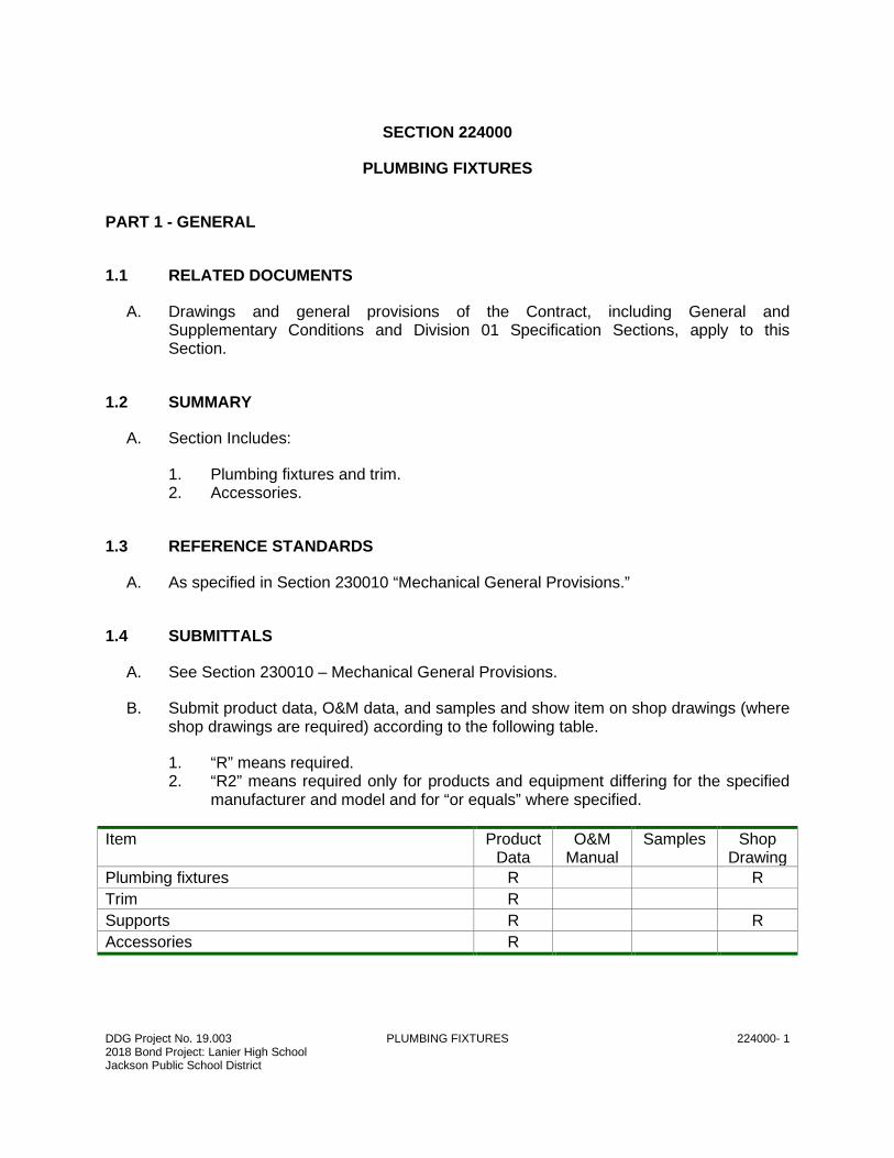
SECTION 224000
PLUMBING FIXTURES
PART 1 - GENERAL
1.1 RELATED DOCUMENTS
A. Drawings and general provisions of the Contract, including General and Supplementary Conditions and Division 01 Specification Sections, apply to this Section.
1.2 SUMMARY
A. Section Includes:
1. Plumbing fixtures and trim. 2. Accessories.
1.3 REFERENCE STANDARDS
A. As specified in Section 230010 “Mechanical General Provisions.”
1.4 SUBMITTALS
A. See Section 230010 – Mechanical General Provisions.
B. Submit product data, O&M data, and samples and show item on shop drawings (where shop drawings are required) according to the following table.
1. “R” means required. 2. “R2” means required only for products and equipment differing for the specified
manufacturer and model and for “or equals” where specified.
Item Product Data
O&M Manual
Samples Shop Drawing
Plumbing fixtures R R
Trim R
Supports R R
Accessories R
DDG Project No. 19.003 PLUMBING FIXTURES 224000- 2 2018 Bond Project: Lanier High School Jackson Public School District
1.5 QUALITY ASSURANCE
A. As specified in Section 230010 “Mechanical General Provisions.”
B. Source Limitations: Obtain plumbing fixtures, faucets, and other components of each category through one source from a single manufacturer.
1. Exception: If fixtures, faucets, or other components are not available from a single manufacturer, obtain similar products from other manufacturers specified for that category.
C. Electrical Components, Devices, and Accessories: Listed and labeled as defined in NFPA 70, Article 100, by a testing agency acceptable to authorities having jurisdiction, and marked for intended use.
D. Regulatory Requirements: Comply with requirements in ICC A117.1, "Accessible and Usable Buildings and Facilities"; Public Law 90-480, "Architectural Barriers Act"; and Public Law 101-336, "Americans with Disabilities Act".
E. Regulatory Requirements: Comply with requirements in Public Law 102-486, "Energy Policy Act," about water flow and consumption rates for plumbing fixtures.
F. NSF Standard: Comply with NSF 61, "Drinking Water System Components--Health Effects," for fixture materials that will be in contact with potable water.
G. Select combinations of fixtures and trim, faucets, fittings, and other components that are compatible.
H. Comply with the following applicable standards and other requirements specified for plumbing fixtures:
1. Enameled, Cast-Iron Fixtures: ASME A112.19.1M. 2. Hand Sinks: NSF 2 construction. 3. Porcelain-Enameled, Formed-Steel Fixtures: ASME A112.19.4M. 4. Stainless-Steel Fixtures Other Than Service Sinks: ASME A112.19.3M. 5. Vitreous-China Fixtures: ASME A112.19.2M. 6. Water-Closet, Flush Valve, Tank Trim: ASME A112.19.5. 7. Water-Closet, Flushometer Tank Trim: ASSE 1037.
I. Comply with the following applicable standards and other requirements specified for sink faucets:
1. Backflow Protection Devices for Faucets with Side Spray: ASME A112.18.3M. 2. Backflow Protection Devices for Faucets with Hose-Thread Outlet: ASME
A112.18.3M. 3. Diverter Valves for Faucets with Hose Spray: ASSE 1025. 4. Faucet Hose: ASTM D 3901. 5. Faucets: ASME A112.18.1M. 6. Hose-Connection Vacuum Breakers: ASSE 1011. 7. Hose-Coupling Threads: ASME B1.20.7.
DDG Project No. 19.003 PLUMBING FIXTURES 224000- 3 2018 Bond Project: Lanier High School Jackson Public School District
8. Integral, Atmospheric Vacuum Breakers: ASSE 1001. 9. NSF Materials: NSF 61. 10. Pipe Threads: ASME B1.20.1. 11. Sensor-Actuated Faucets and Electrical Devices: UL 1951. 12. Supply and Drain Fittings: ASME A112.18.1M.
J. Comply with the following applicable standards and other requirements specified for miscellaneous fittings:
1. Atmospheric Vacuum Breakers: ASSE 1001. 2. Brass and Copper Supplies: ASME A112.18.1M. 3. Manual-Operation Flushometers: ASSE 1037. 4. Plastic Tubular Fittings and Piping: ASTM F 409. 5. Sensor-Operation Flushometers: ASSE 1037 and UL 1951. 6. Tubular Brass Drainage Fittings and Piping: ASME A112.18.1M.
K. Comply with the following applicable standards and other requirements specified for miscellaneous components:
1. Disposers: ASSE 1008 and UL 430. 2. Floor Drains: ASME A112.21.1M. 3. Grab Bars: ASTM F 446. 4. Hose-Coupling Threads: ASME B1.20.7. 5. Hot-Water Dispensers: ASSE 1023 and UL 499. 6. Off-Floor Fixture Supports: ASME A112.6.1M. 7. Pipe Threads: ASME B1.20.1. 8. Plastic Toilet Seats: ANSI Z124.5. 9. Supply and Drain Protective Shielding Guards: ICC A117.1.
1.6 COORDINATION
A. Coordinate roughing-in and final plumbing fixture locations and verify that fixtures can be installed to comply with original design and referenced standards.
1.7 MAINTENANCE MATERIAL SUBMITTALS
A. Provide two service kits for each type of faucet, flush valve, shower/tub valve and all other trim/accessories having serviceable parts.
PART 2 - PRODUCTS
2.1 MATERIALS
A. General:
DDG Project No. 19.003 PLUMBING FIXTURES 224000- 4 2018 Bond Project: Lanier High School Jackson Public School District
1. Provide fixtures and trim complete for proper installation as described in the manufacturer’s catalog with the modifications as shown on Plumbing Fixture Schedule in the plans or specifications.
2. All fixtures, specified to be of vitreous ware, shall be of a quality known commercially as “twice fired” vitreous chinaware of the best quality, nonabsorbent, burned so that the whole mass is thoroughly fused and vitrified producing a material white in color, which when fractured will show a homogeneous mass, close-grained and free from pores. The glazed and vitreous china fixtures shall be white, thoroughly fused and united to the body, without discoloration, chips, or flaws and shall be free from cracks. Warped or otherwise imperfect fixtures will not be acceptable.
3. Factory grind back and bases of fixtures smooth. 4. Enamelware to be white cast iron with acid-resisting enamel. 5. Unless otherwise specified, water closets to have a waste passage to pass a 2-
1/2-inch ball minimum. Bolt water closets to flanges with a 1-inch thick rubber foam gasket.
6. Fixture trim and exposed metal items shall be polished chrome-plated unless otherwise noted, and pipes passing through walls shall have polished chrome-plated escutcheon plates. All stainless steel shall be satin brushed (US32D) finish unless noted otherwise.
7. Fixtures shall be free from imperfections, true as to line, angles, curves, and color; smooth, watertight and practically noiseless in operation.
8. Exposed Pipe, Trim Including Fittings, Traps, Escutcheons, Valves, Valve Handles, and Accessories: Above and Below Fixtures:
a. Polished chrome plated CP brass. b. Set-screw cast brass escutcheons for piping. c. Covering tubes not permitted. d. Provide Hudee stainless steel rims, as applicable, for non-self-rimming
counter mounted fixtures.
9. Supply Fixtures With:
a. Renewable seats or replaceable internal units. b. Compositional washers.
2.2 MANUFACTURERS
A. Named manufacturer model numbers used as example of item and establish minimum level of quality and minimum standard options. Equivalent models are acceptable.
1. Vitreous china fixtures:
a. American Standard. b. Toto. c. Zurn. d. Kohler. e. Or equal.
DDG Project No. 19.003 PLUMBING FIXTURES 224000- 5 2018 Bond Project: Lanier High School Jackson Public School District
2. Lavatory trim:
a. Zurn. b. Kohler. c. Delta. d. Or equal.
3. Fixture carriers:
a. Wade. b. Zurn. c. J.R. Smith d. Or equal. e. Or equal.
2.3 FLUSH VALVE PLUMBING FIXTURES – GENERAL
A. Provide vacuum breakers and angle control-stop valves for each flush valve. Vacuum breakers shall conform to ASSE 1001. Exposed to view and pressure containing components of flush valves, vacuum breaker, angle control-stop valve, tail pieces, slip nuts, escutcheon plates, and wall plates shall be chromium-plated copper alloy or polished stainless steel. Water flushing volume of the flush valve shall not exceed the gallons per flush required below, and is factory set as required by the fixture. Mount flush valves not less than 11 inches above neither the fixture nor more than 44 inches above the floor for ADA accessible fixtures. For ADA accessible water closets, controls for flush valves shall be located on the wide side of the toilet area.
B. See plumbing fixture schedule for basis of design and options required.
2.4 WATER CLOSETS
A. See Construction Drawings for basis of design water closets.
1. Bowl: White vitreous china, elongated bowl, 1-1/2-inch top spud, 2-1/4-inch passageway, white bolt caps.
2. Flush Valve: Manual flush valve. 3. Seat: White open front, plastic seat, self-sustaining with check hinge. 4. Stop and supply: Chrome plated, solid brass angle stops with one quarter turn
handle and cast brass escutcheon with setscrew. Flexible chrome plated copper closet risers, with chrome plated, cast brass, flange with setscrew.
5. Accessories: With trap primer, where indicated.
2.5 LAVATORIES
A. See Construction Drawings for basis of design lavatories.
DDG Project No. 19.003 PLUMBING FIXTURES 224000- 6 2018 Bond Project: Lanier High School Jackson Public School District
1. Lavatory: Vitreous china with overflow, See architectural drawings for mounting height.
2. Faucet: Manually operated, solid-brass, polished chrome finish. 3. Strainer: 6-inch offset drain and tailpiece, brass, 1-1/4-inch. 4. Stops and supplies: Two chrome plated, solid brass angle stops with one quarter
turn handle and cast brass escutcheon with setscrew, two flexible chrome plated copper lavatory risers, with chrome plated, cast brass, flange with setscrew.
5. Trap: 1-1/4-inch, chrome plated, cast brass, P-trap with cleanout with cast brass escutcheon with setscrew and brass nuts.
6. Accessories:
a. Adjustable floor mounted chair carrier, Zurn or equal. Carriers shall be fully compatible with each fixture.
b. Trap, supply and stop insulation kit Truebro Handi Lav-Guard or equal.
2.6 CARRIER SUPPORTS
A. Where wall hung plumbing fixtures (water closets, urinals, lavatories, electric drinking fountains, or sinks) are installed back-to- back and carriers are specified, provide one carrier to serve both fixtures in lieu of individual carriers. Provide appropriate carriers for all wall mounted plumbing fixtures, and as indicated elsewhere in these specifications or on the drawings, or as required. All carriers shall be concealed, floor mounted type unless otherwise approved by the Architect.
2.7 PROTECTIVE SHIELDING GUARDS
A. Protective Shielding Guard: Manufactured, plastic covering or enclosure for hot- and cold-water supplies and trap and drain piping and complying with ADA requirements Truebro Lav Guard model #102 and model #105 or equal.
PART 3 - EXECUTION
3.1 EXAMINATION
A. Examine roughing-in for water soil and for waste piping systems and supports to verify actual locations and sizes of piping connections and that locations and types of supports match those indicated, before plumbing fixture installation. Use manufacturer's roughing-in data if roughing-in data are not indicated.
B. Examine walls and floors for suitable conditions where water closets will be installed.
C. Proceed with installation only after unsatisfactory conditions have been corrected.
DDG Project No. 19.003 PLUMBING FIXTURES 224000- 7 2018 Bond Project: Lanier High School Jackson Public School District
3.2 APPLICATIONS
A. Include supports for plumbing fixtures according to the following:
1. Heavy-Duty, Floor Mounted Chair Carriers: For all wall mounted plumbing fixtures.
B. Include fitting insulation kits for accessible fixtures according to the following:
1. Lavatories: Cover Hot-and cold-water supplies, stops and handles, drain, trap, and waste to wall.
2. Fixtures with Offset Drain: Cover hot-and cold-water supplies, offset drain, trap, and waste to wall.
3. Other Fixtures: Cover exposed fittings below fixture.
3.3 FIXTURE INSTALLATION
A. Assemble fixtures, trim, fittings, and other components according to manufacturers' written instructions.
B. New sanitary piping shall match existing piping type and size. New domestic water piping shall be copper.
C. Insulate new domestic cold and hot water piping. Install new pipe insulation on piping insulation disturbed as part of work performed under this contract. New insulation type and thickness shall match existing.
D. For wall-hanging fixtures, install off-floor supports/carriers affixed to building substrate. See Architectural Drawings for fixture heights. If no fixture height is included consult Architect.
E. Install back-outlet, wall-hanging fixtures onto waste fitting seals and attach to supports.
F. Install floor-mounting fixtures on closet flanges or other attachments to piping or building substrate. Closet flanges shall be anchored to the floor per manufacturer’s recommendations.
G. Install wall-hanging fixtures with tubular waste piping attached to supports.
H. Install counter-mounting fixtures in and attached to casework.
I. Install fixtures level and plumb according to manufacturers' written instructions and roughing-in drawings.
J. Install water-supply piping with stop on each supply to each fixture to be connected to water distribution piping. Attach supplies to supports or substrate within pipe spaces behind fixtures. Install stops in locations where they can be easily reached for operation.
DDG Project No. 19.003 PLUMBING FIXTURES 224000- 8 2018 Bond Project: Lanier High School Jackson Public School District
K. Install trap and tubular waste piping on drain outlet of each fixture to be directly connected to sanitary drainage system.
L. Install flushometer valves for accessible water closets and urinals with handle mounted on wide side of compartment. Install other actuators in locations that are easy for people with disabilities to reach.
M. On wall mounted water closets, where water closet waste pipe has to be offset due to beam interference, provide correct carrier and/or additional piping necessary to eliminate relocation of water closet. On floor mounted water closets, offset shall not be more than 3/4” and non-reducing.
N. Install toilet seats on water closets.
O. Install faucet-spout fittings with specified flow rates and patterns in faucet spouts if faucets are not available with required rates and patterns. Include adapters if required.
P. Install water-supply, flow-control fittings with specified flow rates in fixture supplies at stop valves.
Q. Install faucet, flow-control fittings with specified flow rates and patterns in faucet spouts if faucets are not available with required rates and patterns. Include adapters if required.
R. Install traps on fixture outlets.
S. Install escutcheons at piping wall, floor, and ceiling penetrations in exposed, finished locations and within cabinets and millwork. Heavy-duty type escutcheons, with setscrews shall be utilized in exposed applications under wall mounted lavatories and sinks and on exposed piping applications on tank type water closet stops and on exposed piping to flush valves, etc. Light duty slip-on type may be utilized in concealed installations within cabinets. Use deep-pattern escutcheons if required to conceal protruding fittings.
T. Seal joints between fixtures and walls, floors, and counters using sanitary-type, one-part, mildew-resistant, silicone sealant. Grout excessive gaps as required. Match sealant and grout color to fixture color.
U. Items supplied by others as denoted are to be furnished complete with stops, risers, faucets, strainers, tailpiece, and traps. The intent is that this Contractor shall provide all "rough-in" through face of wall and shall connect equipment provided by others, except where otherwise noted.
V. Water Hammer Arrestors.
1. All water supply piping fittings and fixtures shall be protected against water hammer, shock or surge pressure by installation water hammer arrestors.
2. Water hammer arresters shall be installed per the manufacturer’s recommendations. This shall include spacing, sizing, etc.
3. Fixture piping shall be adequately anchored to prevent vibration.
DDG Project No. 19.003 PLUMBING FIXTURES 224000- 9 2018 Bond Project: Lanier High School Jackson Public School District
4. Contractor must guarantee against water hammer at end of project.
3.4 CONNECTIONS
A. Piping installation requirements are specified in other Division 22 and Division 23 Sections. Drawings indicate general arrangement of piping, fittings, and specialties.
B. Connect water supplies from water distribution piping to fixtures.
C. Connect drain piping from fixtures to drainage piping.
D. Supply and Waste Connections to Plumbing Fixtures: Connect fixtures with water supplies, stops, risers, traps, and waste piping. Use size fittings required to match fixtures. Connect to plumbing piping.
E. Supply and Waste Connections to Fixtures and Equipment Specified in Other Sections: Connect fixtures and equipment with water supplies, stops, risers, traps, and waste piping specified. Use size fittings required to match fixtures and equipment. Connect to plumbing piping.
F. Ground equipment.
1. Tighten electrical connectors and terminals according to manufacturer's published torque-tightening values. If manufacturer's torque values are not indicated, use those specified in UL 486A and UL 486B.
G. Arrange for electric-power connections to fixtures and devices that require power. Electric power is specified under Division 26.
3.5 FIELD QUALITY CONTROL
A. Verify that installed fixtures are categories and types specified for locations where installed.
B. Check that fixtures are complete with trim, faucets, fittings, and other specified components.
C. Inspect installed fixtures for damage. Replace damaged fixtures and components.
D. Test installed fixtures after water systems are pressurized for proper operation. Replace malfunctioning fixtures and components, then retest. Repeat procedure until units operate properly.
3.6 ADJUSTING
A. Operate and adjust faucets and controls. Replace damaged and malfunctioning fixtures, fittings, and controls.
DDG Project No. 19.003 PLUMBING FIXTURES 224000- 10 2018 Bond Project: Lanier High School Jackson Public School District
B. Adjust water pressure at faucets, and flushometer valves to produce proper flow and stream.
C. Replace washers and seals of leaking and dripping faucets and stops.
3.7 CLEANING
A. Clean fixtures, faucets, and other fittings with manufacturers' recommended cleaning methods and materials. Do the following:
1. Remove faucet spouts and strainers, remove sediment and debris, and reinstall strainers and spouts.
2. Remove sediment and debris from drains.
3.8 PROTECTION
A. Provide protective covering for installed fixtures and fittings throughout construction.
B. Do not allow use of fixtures for temporary facilities unless approved in writing by Owner.
C. Replace any fixtures or equipment broken, cracked, discolored, pitted, or otherwise imperfect.
3.9 OPERATIONAL TESTS
A. Pour at least five (5) gallons of water into every floor drain to test for pipe stoppage. Remedy all stoppage.
END OF PLUMBING FIXTURES
DDG Project No. 19.003 MECHANICAL GENERAL PROVISIONS 230010- 1 2018 Bond Project: Lanier High School Jackson Public School District
SECTION 230010
MECHANICAL GENERAL PROVISIONS
PART 1 - GENERAL
1.1 RELATED DOCUMENTS
A. Drawings and general provisions of the Contract, including General and Supplementary Conditions and Division 01 Specification Sections, apply to this Section.
1.2 DIVISION OF WORK
A. This section delineates the division of work between Divisions.
B. Consult all other Sections, determine the extent and character of related work and properly coordinate work specified herein with that specified elsewhere to produce a complete and operable installation. This section is provided to assist the Contractor in coordination of work scope but shall not be construed to limit Contractor’s scope of work encompassed by the contract documents.
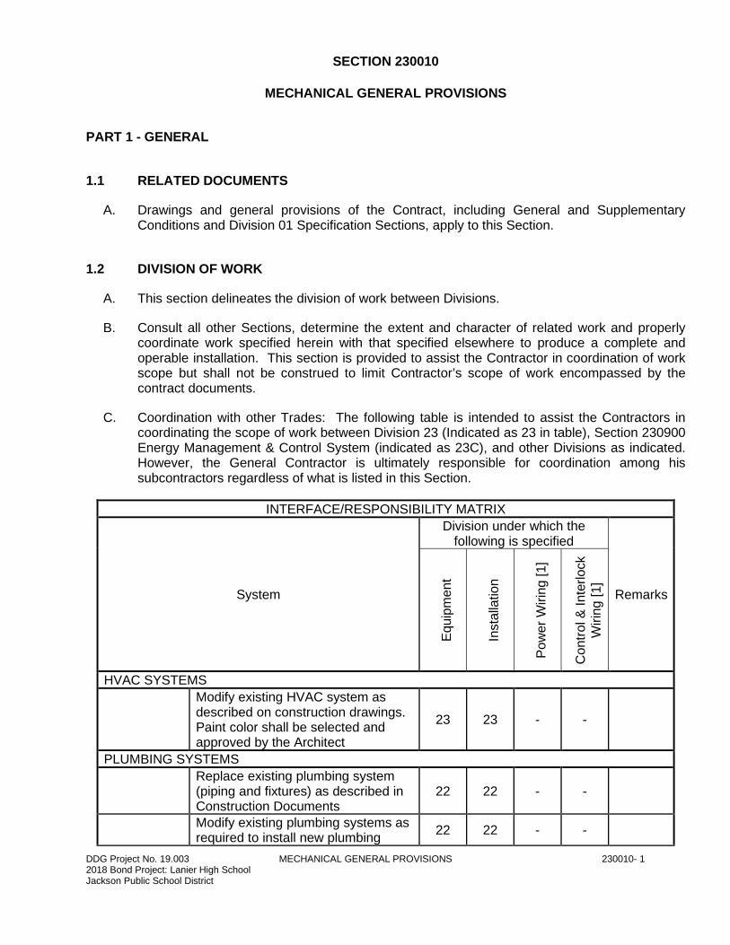
C. Coordination with other Trades: The following table is intended to assist the Contractors in coordinating the scope of work between Division 23 (Indicated as 23 in table), Section 230900 Energy Management & Control System (indicated as 23C), and other Divisions as indicated. However, the General Contractor is ultimately responsible for coordination among his subcontractors regardless of what is listed in this Section.
INTERFACE/RESPONSIBILITY MATRIX
System
Division under which the following is specified
Remarks
Equip
ment
Insta
llation
Pow
er
Wirin
g [1]
Contr
ol &
Inte
rlock
Wirin
g [
1]
HVAC SYSTEMS
Modify existing HVAC system as described on construction drawings. Paint color shall be selected and approved by the Architect
23 23 - -
PLUMBING SYSTEMS
Replace existing plumbing system (piping and fixtures) as described in Construction Documents
22 22 - -
Modify existing plumbing systems as required to install new plumbing
22 22 - -
DDG Project No. 19.003 MECHANICAL GENERAL PROVISIONS 230010- 2 2018 Bond Project: Lanier High School Jackson Public School District
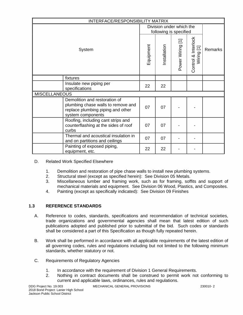
INTERFACE/RESPONSIBILITY MATRIX
System
Division under which the following is specified
Remarks
Equip
ment
Insta
llation
Pow
er
Wirin
g [1]
Contr
ol &
Inte
rlock
Wirin
g [
1]
fixtures
Insulate new piping per specifications
22 22
MISCELLANEOUS
Demolition and restoration of plumbing chase walls to remove and replace plumbing piping and other system components
07 07 - -
Roofing, including cant strips and counterflashing at the sides of roof curbs
07 07 - -
Thermal and acoustical insulation in and on partitions and ceilings
07 07 - -
Painting of exposed piping, equipment, etc.
22 22 - -
D. Related Work Specified Elsewhere
1. Demolition and restoration of pipe chase walls to install new plumbing systems. 2. Structural steel (except as specified herein): See Division 05 Metals. 3. Miscellaneous lumber and framing work, such as for framing, soffits and support of
mechanical materials and equipment. See Division 06 Wood, Plastics, and Composites. 4. Painting (except as specifically indicated): See Division 09 Finishes
1.3 REFERENCE STANDARDS
A. Reference to codes, standards, specifications and recommendation of technical societies, trade organizations and governmental agencies shall mean that latest edition of such publications adopted and published prior to submittal of the bid. Such codes or standards shall be considered a part of this Specification as though fully repeated herein.
B. Work shall be performed in accordance with all applicable requirements of the latest edition of all governing codes, rules and regulations including but not limited to the following minimum standards, whether statutory or not.
C. Requirements of Regulatory Agencies
1. In accordance with the requirement of Division 1 General Requirements. 2. Nothing in contract documents shall be construed to permit work not conforming to
current and applicable laws, ordinances, rules and regulations.
DDG Project No. 19.003 MECHANICAL GENERAL PROVISIONS 230010- 3 2018 Bond Project: Lanier High School Jackson Public School District
3. Where contract documents exceed requirements of applicable laws, ordinances, rules and regulations, comply with documents establishing the more stringent requirement.
4. It is not the intent of contract documents to repeat requirements of codes except where necessary for completeness or clarity.
5. Comply with the Safety Orders issued by OSHA and any other safety, health or environmental regulations of the State of Mississippi and any districts having jurisdictional authority. Where an omission or conflict appears between OSHA requirements and the Drawings and Specifications, OSHA requirements shall take precedence.
6. Applicable codes as listed below, in addition to others specified in individual sections.
a. American Society of Heating, Refrigerating and Air Conditioning Engineers (ASHRAE) – Standard 90.1-2010 “Energy Standard for Buildings Except Low-Rise Residential Buildings”.
b. International Building Code (IPC) – 2015. c. International Mechanical Code (IMC) – 2015. d. International Plumbing Code (IPC) - 2015. e. NFPA 1 – 2012, Fire Code f. NFPA 70 - 2008, National Electric Code g. NFPA 90A - 2009, Installation of Air Conditioning and Ventilating Systems
D. Published specifications, standards, tests or recommended method of trade, industry or governmental organizations as listed below apply to all work in Division 23 HVAC, in addition to other standards which may be specified in individual sections.
E. All base material shall meet ASTM and ANSI standards.
F. All Gas Fired Devices: Comply with standards and bear label of AGA.
G. All Pressure Vessels, Relief Valves, Safety Relief Valves and Safety Valves: Comply with standards, ASME stamped.
H. All Electrical Devices and Wiring
1. Conform to standards of NEC 2. All devices UL or ETL listed and identified
I. Guidelines and Standards: The latest edition of guidelines and standards published by the following govern the Mechanical Systems and associated support system design. The systems shall be designed to meet or exceed these guidelines and standards.
AABC Associated Air Balance Council
ADC Air Diffuser Balance Council
AGA American Gas Association
AMCA Air Movement and Control Association, Inc.
ANSI American National Standards Institute
ARI Air Conditioning and Refrigeration Institute
ASC Adhesive and Sealant Council
ASHRAE American Society of Heating, Refrigeration and Air Conditioning Engineers
ASME American Society of Mechanical Engineers
ASSE American Society of Sanitary Engineers
DDG Project No. 19.003 MECHANICAL GENERAL PROVISIONS 230010- 4 2018 Bond Project: Lanier High School Jackson Public School District
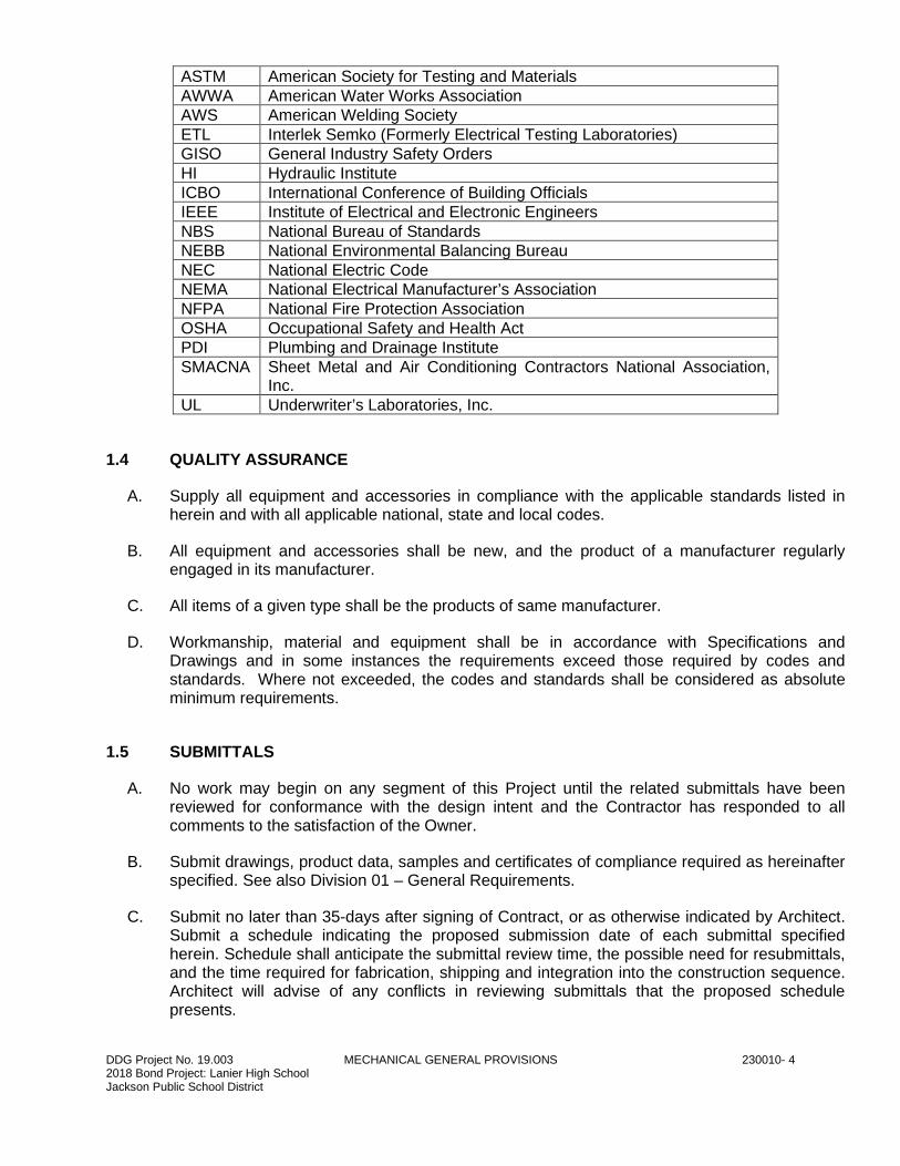
ASTM American Society for Testing and Materials
AWWA American Water Works Association
AWS American Welding Society
ETL Interlek Semko (Formerly Electrical Testing Laboratories)
GISO General Industry Safety Orders
HI Hydraulic Institute
ICBO International Conference of Building Officials
IEEE Institute of Electrical and Electronic Engineers
NBS National Bureau of Standards
NEBB National Environmental Balancing Bureau
NEC National Electric Code
NEMA National Electrical Manufacturer’s Association
NFPA National Fire Protection Association
OSHA Occupational Safety and Health Act
PDI Plumbing and Drainage Institute
SMACNA Sheet Metal and Air Conditioning Contractors National Association, Inc.
UL Underwriter’s Laboratories, Inc.
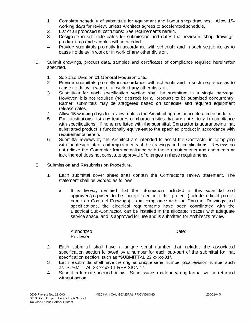
1.4 QUALITY ASSURANCE
A. Supply all equipment and accessories in compliance with the applicable standards listed in herein and with all applicable national, state and local codes.
B. All equipment and accessories shall be new, and the product of a manufacturer regularly engaged in its manufacturer.
C. All items of a given type shall be the products of same manufacturer.
D. Workmanship, material and equipment shall be in accordance with Specifications and Drawings and in some instances the requirements exceed those required by codes and standards. Where not exceeded, the codes and standards shall be considered as absolute minimum requirements.
1.5 SUBMITTALS
A. No work may begin on any segment of this Project until the related submittals have been reviewed for conformance with the design intent and the Contractor has responded to all comments to the satisfaction of the Owner.
B. Submit drawings, product data, samples and certificates of compliance required as hereinafter specified. See also Division 01 – General Requirements.
C. Submit no later than 35-days after signing of Contract, or as otherwise indicated by Architect. Submit a schedule indicating the proposed submission date of each submittal specified herein. Schedule shall anticipate the submittal review time, the possible need for resubmittals, and the time required for fabrication, shipping and integration into the construction sequence. Architect will advise of any conflicts in reviewing submittals that the proposed schedule presents.
DDG Project No. 19.003 MECHANICAL GENERAL PROVISIONS 230010- 5 2018 Bond Project: Lanier High School Jackson Public School District
1. Complete schedule of submittals for equipment and layout shop drawings. Allow 15-working days for review, unless Architect agrees to accelerated schedule.
2. List of all proposed substitutions: See requirements herein. 3. Designate in schedule dates for submission and dates that reviewed shop drawings,
product data and samples will be needed. 4. Provide submittals promptly in accordance with schedule and in such sequence as to
cause no delay in work or in work of any other division.
D. Submit drawings, product data, samples and certificates of compliance required hereinafter specified.
1. See also Division 01 General Requirements. 2. Provide submittals promptly in accordance with schedule and in such sequence as to
cause no delay in work or in work of any other division. 3. Submittals for each specification section shall be submitted in a single package.
However, it is not required (nor desired) for all products to be submitted concurrently. Rather, submittals may be staggered based on schedule and required equipment release dates.
4. Allow 15-working days for review, unless the Architect agrees to accelerated schedule. 5. For substitutions, list any features or characteristics that are not strictly in compliance
with specifications. If none are listed with the submittal, Contractor is guaranteeing that substituted product is functionally equivalent to the specified product in accordance with requirements herein.
6. Submittal reviews by the Architect are intended to assist the Contractor in complying with the design intent and requirements of the drawings and specifications. Reviews do not relieve the Contractor from compliance with these requirements and comments or lack thereof does not constitute approval of changes in these requirements.
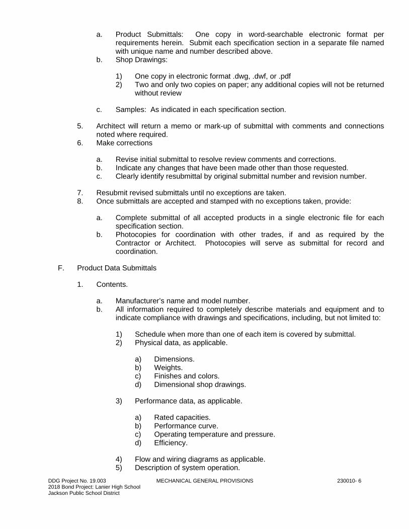
E. Submission and Resubmission Procedure.
1. Each submittal cover sheet shall contain the Contractor’s review statement. The statement shall be worded as follows:
a. It is hereby certified that the information included in this submittal and approved/proposed to be incorporated into this project (include official project name on Contract Drawings), is in compliance with the Contract Drawings and specifications, the electrical requirements have been coordinated with the Electrical Sub-Contractor, can be installed in the allocated spaces with adequate service space, and is approved for use and is submitted for Architect’s review.
Authorized Reviewer:
Date:
2. Each submittal shall have a unique serial number that includes the associated specification section followed by a number for each sub-part of the submittal for that specification section, such as “SUBMITTAL 23 xx xx-01”.
3. Each resubmittal shall have the original unique serial number plus revision number such as “SUBMITTAL 23 xx xx-01 REVISION 1”.
4. Submit in format specified below. Submissions made in wrong format will be returned without action.
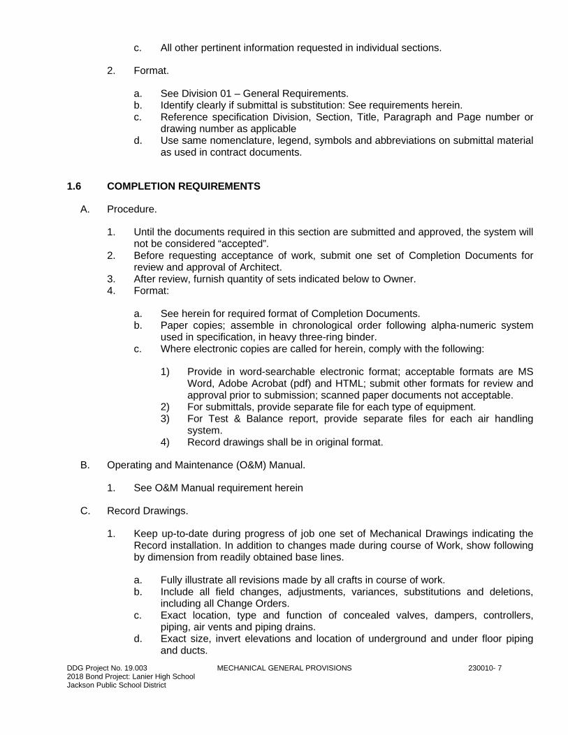
DDG Project No. 19.003 MECHANICAL GENERAL PROVISIONS 230010- 6 2018 Bond Project: Lanier High School Jackson Public School District
a. Product Submittals: One copy in word-searchable electronic format per requirements herein. Submit each specification section in a separate file named with unique name and number described above.
b. Shop Drawings:
1) One copy in electronic format .dwg, .dwf, or .pdf 2) Two and only two copies on paper; any additional copies will not be returned
without review
c. Samples: As indicated in each specification section.
5. Architect will return a memo or mark-up of submittal with comments and connections noted where required.
6. Make corrections
a. Revise initial submittal to resolve review comments and corrections. b. Indicate any changes that have been made other than those requested. c. Clearly identify resubmittal by original submittal number and revision number.
7. Resubmit revised submittals until no exceptions are taken. 8. Once submittals are accepted and stamped with no exceptions taken, provide:
a. Complete submittal of all accepted products in a single electronic file for each specification section.
b. Photocopies for coordination with other trades, if and as required by the Contractor or Architect. Photocopies will serve as submittal for record and coordination.
F. Product Data Submittals
1. Contents.
a. Manufacturer’s name and model number. b. All information required to completely describe materials and equipment and to
indicate compliance with drawings and specifications, including, but not limited to:
1) Schedule when more than one of each item is covered by submittal. 2) Physical data, as applicable.
a) Dimensions. b) Weights. c) Finishes and colors. d) Dimensional shop drawings.
3) Performance data, as applicable.
a) Rated capacities. b) Performance curve. c) Operating temperature and pressure. d) Efficiency.
4) Flow and wiring diagrams as applicable. 5) Description of system operation.
DDG Project No. 19.003 MECHANICAL GENERAL PROVISIONS 230010- 7 2018 Bond Project: Lanier High School Jackson Public School District
c. All other pertinent information requested in individual sections.
2. Format.
a. See Division 01 – General Requirements. b. Identify clearly if submittal is substitution: See requirements herein. c. Reference specification Division, Section, Title, Paragraph and Page number or
drawing number as applicable d. Use same nomenclature, legend, symbols and abbreviations on submittal material
as used in contract documents.
1.6 COMPLETION REQUIREMENTS
A. Procedure.
1. Until the documents required in this section are submitted and approved, the system will not be considered “accepted”.
2. Before requesting acceptance of work, submit one set of Completion Documents for review and approval of Architect.
3. After review, furnish quantity of sets indicated below to Owner. 4. Format:
a. See herein for required format of Completion Documents. b. Paper copies; assemble in chronological order following alpha-numeric system
used in specification, in heavy three-ring binder. c. Where electronic copies are called for herein, comply with the following:
1) Provide in word-searchable electronic format; acceptable formats are MS Word, Adobe Acrobat (pdf) and HTML; submit other formats for review and approval prior to submission; scanned paper documents not acceptable.
2) For submittals, provide separate file for each type of equipment. 3) For Test & Balance report, provide separate files for each air handling
system. 4) Record drawings shall be in original format.
B. Operating and Maintenance (O&M) Manual.
1. See O&M Manual requirement herein
C. Record Drawings.
1. Keep up-to-date during progress of job one set of Mechanical Drawings indicating the Record installation. In addition to changes made during course of Work, show following by dimension from readily obtained base lines.
a. Fully illustrate all revisions made by all crafts in course of work. b. Include all field changes, adjustments, variances, substitutions and deletions,
including all Change Orders. c. Exact location, type and function of concealed valves, dampers, controllers,
piping, air vents and piping drains. d. Exact size, invert elevations and location of underground and under floor piping
and ducts.
DDG Project No. 19.003 MECHANICAL GENERAL PROVISIONS 230010- 8 2018 Bond Project: Lanier High School Jackson Public School District
1) Progress drawing set shall be available for inspection by Architect weekly. 2) Update engineering design drawings and shop drawings to reflect revisions
and additional data listed above at completion of Project.
e. Original engineering design drawings will be provided to Contactor in electronic format compatible with AutoCAD version 2010 or later.
f. Both shop and engineering design drawings shall be in format compatible with AutoCAD version 2010 or later.
g. Drawings required to be updated if revisions were made.
1) Floor plans. 2) Shop drawings required herein. 3) Sections. 4) Riser diagrams.
D. Test and Balance Reports.
1. See Section 230593 – Testing, Adjusting, and Balancing for HVAC.
E. Training Materials.
1. See Training Materials requirements herein.
F. Miscellaneous Certificates.
1. Pressure and Leakage Test documentation/certificates. 2. Training/Instruction completion certificates. 3. Fire Marshal and Fire Department approvals of system, as required. 4. Final inspection certificate signed by governing authorities. 5. Warranty period, including start and end period. 6. Field test report, including as applicable. 7. Start-up documents with date and name of technician. 8. Piping pressure tests. 9. Flex coupled pump alignment verification. 10. Duct leakage and pressure tests. 11. Drain pan drainage tests. 12. Letters from manufacturers certifying their supervision of equipment installation and
start-up procedures. 13. Machinery vibration test reports. 14. Certificates of sterilization/chlorination of plumbing systems. 15. Others as specified herein and in other Division 23 – Mechanical sections.
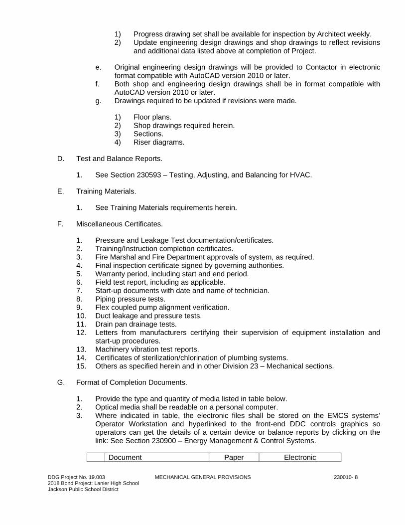
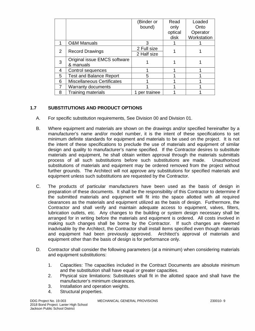
G. Format of Completion Documents.
1. Provide the type and quantity of media listed in table below. 2. Optical media shall be readable on a personal computer. 3. Where indicated in table, the electronic files shall be stored on the EMCS systems’
Operator Workstation and hyperlinked to the front-end DDC controls graphics so operators can get the details of a certain device or balance reports by clicking on the link: See Section 230900 – Energy Management & Control Systems.
Document Paper Electronic
DDG Project No. 19.003 MECHANICAL GENERAL PROVISIONS 230010- 9 2018 Bond Project: Lanier High School Jackson Public School District
(Binder or bound)
Read only
optical disk
Loaded Onto
Operator Workstation
1 O&M Manuals 3 1 1
2 Record Drawings 2 Full size
1 1 2 Half size
3 Original issue EMCS software & manuals
1 1 1
4 Control sequences 1 1 1
5 Test and Balance Report 5 1 1
6 Miscellaneous Certificates 1 1 1
7 Warranty documents 1 1 1
8 Training materials 1 per trainee 1 1
1.7 SUBSTITUTIONS AND PRODUCT OPTIONS
A. For specific substitution requirements, See Division 00 and Division 01.
B. Where equipment and materials are shown on the drawings and/or specified hereinafter by a manufacturer’s name and/or model number, it is the intent of these specifications to set minimum definite standards for equipment and materials to be used on the project. It is not the intent of these specifications to preclude the use of materials and equipment of similar design and quality to manufacturer’s name specified. If the Contractor desires to substitute materials and equipment, he shall obtain written approval through the materials submittals process of all such substitutions before such substitutions are made. Unauthorized substitutions of materials and equipment may be ordered removed from the project without further grounds. The Architect will not approve any substitutions for specified materials and equipment unless such substitutions are requested by the Contractor.
C. The products of particular manufacturers have been used as the basis of design in preparation of these documents. It shall be the responsibility of this Contractor to determine if the submitted materials and equipment will fit into the space allotted with all required clearances as the materials and equipment utilized as the basis of design. Furthermore, the Contractor and shall verify and maintain adequate access to equipment, valves, filters, lubrication outlets, etc. Any changes to the building or system design necessary shall be arranged for in writing before the materials and equipment is ordered. All costs involved in making such changes shall be borne by the Contractor. If such changes are deemed inadvisable by the Architect, the Contractor shall install items specified even though materials and equipment had been previously approved. Architect’s approval of materials and equipment other than the basis of design is for performance only.
D. Contractor shall consider the following parameters (at a minimum) when considering materials and equipment substitutions:
1. Capacities: The capacities included in the Contract Documents are absolute minimum and the substitution shall have equal or greater capacities.
2. Physical size limitations: Substitutes shall fit in the allotted space and shall have the manufacturer’s minimum clearances.
3. Installation and operation weights. 4. Structural properties.

DDG Project No. 19.003 MECHANICAL GENERAL PROVISIONS 230010- 10 2018 Bond Project: Lanier High School Jackson Public School District
5. Noise levels. 6. Vibration. 7. Interchangeability. 8. Accessibility for maintenance, operation, and replacement. 9. Compatibility with other materials and assemblies. 10. Equal quality and style.
1.8 DESCRIPTION OF BID DOCUMENTS
A. The Contractor shall be responsible for becoming thoroughly acquainted with all Contract Document contents that affect his work under this contract. Work required under this section includes, but is not limited to, all material, equipment transportation, services and labor required to complete the entire mechanical system as required by the Contract Documents.
B. The Specifications and the associated Drawings are complimentary, and any portion of the work described in one shall be provided as if described in both.
C. Specifications.
1. Specifications, in general, describe quality and character of materials and equipment. 2. Specifications are of simplified form and include incomplete sentences. 3. Words or phrases such as “The Contractor shall,” “shall be,” “furnish,” “provide,” “a,”
“an,” “the,” and “all” have often been omitted from specifications for brevity.
D. Drawings.
1. Drawings are diagrammatic in nature and, unless explicitly dimensioned, indicate approximate locations of apparatus, equipment, ductwork and piping. Changes in the location, and offsets, of same which are not shown on the Drawings but are necessary in order to accommodate building conditions and coordination with the work of other trades, shall be made during the preparation of coordination drawings and prior to initial installation, without additional cost to the Owner. Contractor shall install all system components in such a manner as to conform to the structure, avoid obstructions, preserve headroom, keep openings and passageways clear and maintain required servicing clearances without further instructions or additional cost to the Owner.
2. Scaled and figured dimensions are approximate and are for estimating purposes only. Indicated dimensions are limiting dimensions where noted. Duct and piping elevations are indicated for initial coordination; final requirements shall be determined by the Contractor after final coordination with other trades.
3. Before proceeding with work, check and verify all dimensions in field. 4. Assume all responsibility for fitting of materials and equipment to other parts of
equipment and structure. 5. Make adjustments that may be necessary or requested in order to resolve space
problems, preserve headroom and avoid architectural openings, structural members and work of other trades.
6. It is intended that all mechanical, plumbing and fire protection devices, piping, etc. be located symmetrically with all architectural elements. Refer to Architectural, Structural, Plumbing, Fire Protection, Mechanical and Electrical Specifications and Drawings in completing the required coordination.
7. The Contractor shall fully inform himself regarding any and all peculiarities and limitations of the spaces available for the installation of all work and materials furnished
DDG Project No. 19.003 MECHANICAL GENERAL PROVISIONS 230010- 11 2018 Bond Project: Lanier High School Jackson Public School District
and installed under this Contract. He shall exercise due and particular caution to determine that all parts of his work are made readily accessible.
8. The Contractor shall study all drawings and specifications to determine any conflict with all applicable ordinances and statutes. Any discrepancies shall be reported to the Owner and any changes shall be shown on the as-built drawings with the additional work performed at no cost to the Owner.
9. The submittal of his bid shall indicate the Contractor has examined the site, drawings and specifications and has included all required allowances in his bid. No allowance shall be made for any error or omission resulting from the Contractor’s failure to visit job site and to review drawings and specifications. The Contractor’s bid shall include costs for all required drawings and changes as outlined above at no cost to the Owner.
10. Provide access to equipment and apparatus requiring operation, service or maintenance throughout the life of the system.
E. Do not use equipment exceeding dimensions indicated on drawings or equipment or arrangements that reduce required clearances or exceed specified maximum dimensions.
F. If any part of Specifications or Drawings appears unclear or contradictory, apply to Architect for an interpretation and decision prior to as early as possible.
1. Do not proceed with work without the decision of the Architect.
1.9 DEFINITIONS
A. In addition to those defined in Division 01 – General Requirements, the following additional definitions shall apply. Definitions of term used in Division 23 HVAC may differ from those given in general and supplementary conditions.
B. “Provide”: to furnish, supply, install and connect up complete and ready safe and regular operation of particular work referred to unless specifically noted.
C. “Supply”: to purchase, procure, acquire and deliver complete with related accessories.
D. “Work”: includes labor, materials, apparatus, controls, equipment services and all related accessories necessary for the proper and complete installation of complete systems.
E. “Piping”: includes pipe, tube, fittings, flanges, valves, controls, strainers, hangers, supports, unions, traps, drains, insulation and all related accessories.
F. “Wiring”: includes raceway, fittings, wire, boxes and all related accessories.
G. “Concealed”: not in view, installed in masonry or other construction, within furred spaces, double partitions, hung ceiling, trenches, crawl spaces, or enclosures.
H. “Exposed”: in view, not installed underground or “concealed” as defined above. Exposed piping, conduit, or ductwork is that which can be seen when the building is complete without opening or removing access doors or panels or accessible ceiling components.
I. “Control or Actuated Devices”: includes automatic sensing and switching devices such as thermostats, pressure, float, flow, electro-pneumatic switches and electrodes controlling operation of equipment.
DDG Project No. 19.003 MECHANICAL GENERAL PROVISIONS 230010- 12 2018 Bond Project: Lanier High School Jackson Public School District
J. “Indicated,” “shown” or “noted”: as indicated, shown or noted on drawings or specifications.
K. “Reviewed,” “approved,” or “directed”, as reviewed, approved or directed by or to Owner.
L. “Motor Controllers”: starter, variable speed drives and other devices controlling the operation of motors.
1.10 PROJECT CONDITIONS
A. Examine site related work and surfaces before starting work of any Section.
1. In case of conflict, the most stringent takes precedence. 2. For purposes of clarity and legibility, Drawings are essentially diagrammatic to extent
that many offsets, bends, unions, special fittings, exact locations of items are not indicated, unless specifically dimensioned. Especially note a number of required duct and pipe offsets to coordinate with structure and not shown. Coordinate dimensioned conditions, including invert elevations, with other trades prior to installation by any trade.
3. Exact routing of piping, ductwork, etc. shall be governed by structural conditions and other obstructions. Not all offsets in ductwork or piping are shown on the Drawings. Determine which item to offset or relocate. Maintain required slope in piping. Make use of data in Contract Documents. In addition, Architect reserves right, at no additional cost to the Owner, to make any reasonable change in location of mechanical items, exposed at ceiling or on walls, to group them into orderly relationships or increase their utility. Verify Owner’s requirements in this regard prior to rough-in.
4. Take dimensions, location of doors, partitions, similar physical features from Architectural Drawings. Verify at Site under this Division. Consult Architectural Drawings for exact location of outlets to center with Architectural features, panels, etc., at the appropriate location shown on Mechanical Drawings.
5. Mounting heights of brackets, outlets, etc., as required. 6. Report to Architect, in writing, conditions which will prevent proper provision of this work. 7. Beginning work of any Section without reporting unsuitable conditions to Architect
constitutes acceptance of conditions by Contractor. 8. Perform any required removal, repair or replacement of this work caused by unsuitable
conditions at no additional cost to the Owner.
B. Coordination.
1. Work out all “tight” conditions involving Work specified under this Division and work in other Divisions in advance of installation, if necessary, and before Work proceeds in these areas, prepare supplementary Drawings under this Division for review showing all Work in congested area. Provide supplementary Drawings, additional Work necessary to overcome congested conditions, at no additional cost to the Owner.
2. Conflicts: Difference or disputes concerning coordination, interference or extent of Work between sections shall be decided as follows:
a. Install mechanical and electrical systems in the following order of preference (those trades listed below another must reroute to resolve the conflict):
1) Drain piping required by code to be sloped. 2) Supply air and exhaust air ductwork connected to fans. 3) Electrical conduit 4 inches and larger. 4) Hydronic piping connected to pumps.
DDG Project No. 19.003 MECHANICAL GENERAL PROVISIONS 230010- 13 2018 Bond Project: Lanier High School Jackson Public School District
5) Domestic water piping. 6) Fire sprinkler piping. 7) Electrical conduit smaller than 4 inches. 8) Transfer ducts and other ductwork not connected to fans. 9) Control system piping and wiring.
b. Continued disputes shall be decided by Contractor and Contractor’s decision, if consistent with Contract Document requirements, shall be final.
3. Supervision: Personally, or through an authorized and competent representative, constantly supervise the work from beginning to completion and, within reason, keep the same foreman and workmen on the Project throughout the Project duration.
4. Provide templates, information and instructions to other Divisions to properly locate hides and openings to be cut or provided.
5. The drawings govern in matters of quantity, and the specifications govern in matters of quality. In the event of conflict within the drawings involving quantities, or within the specifications involving quantities, or within the specifications involving quality, the greater quantity and higher quality shall apply. Such discrepancies shall be noted and clarified in the Bid. No additional allowances will be made because of errors, ambiguities, or omissions that reasonably should have been discovered during the preparation of the Bid.
C. Equipment Rough-in.
1. Rough-in locations shown on Mechanical Drawings for equipment furnished by the Owner and for equipment furnished under other Divisions are approximate only. Obtain exact rough-in locations from following sources.
a. From Shop Drawings for equipment provided under this contract. b. From Architect for Owner Furnished-Contractor installed equipment. c. From existing equipment where such equipment is relocated under this Contract.
2. Verify mechanical characteristics of equipment before starting rough-in. Where conflict exists between equipment and rough-in shown on Drawings obtain clarification from Architect and provide as directed by the Architect at no additional cost to the Owner.
3. Make final connections.
1.11 CLEARANCE FROM ELECTRICAL EQUIPMENT
A. Piping, equipment or ductwork.
1. Prohibited, except as noted in:
a. Electric rooms and closets over equipment, as restricted by NEC. b. Telephone rooms and closets. c. Elevator machine rooms. d. Elevator shafts. e. Electrical switchboard room. f. Communications room.
2. Prohibited, except as noted, over or within 5 feet of:
DDG Project No. 19.003 MECHANICAL GENERAL PROVISIONS 230010- 14 2018 Bond Project: Lanier High School Jackson Public School District
a. Transformers. b. Substations. c. Switchboards. d. Motor control centers. e. Standby power plant. f. Bus ducts. g. Electrical panels. h. Variable frequency drives. i. Starters.
B. Drip pans under piping.
1. Where piping is located over any electrical equipment listed above; reroute piping if possible rather than use drip pan.
2. 28 gage galvanized steel. 3. 18 gage copper. 4. Reinforced and supported. 5. Watertight. 6. With 1-1/4 inch drain outlet piped to floor drain or service sink.
C. Electrical Working Space: Dimensions of the working space shall be a minimum depth of 42" horizontally, the width of the equipment or 30", whichever is greater, and the height of the equipment or 78", whichever is greater. Minimum depth shall be increased to 60" for equipment rated over 600 V.
1.12 PRODUCT DELIVERY, HANDLING AND STORAGE
A. See Division 01 – General Requirements (Product Requirements).
B. Deliver equipment in its original package to prevent damage or entrance of foreign matter. Provide materials on factory provided shipping skids and lifting lugs if required for handling. Provide protective coverings during construction.
C. Handle and ship in accordance with manufacturer’s recommendations.
D. Identify materials and equipment delivered to Site to permit check against approved materials list, reviewed with no exceptions taken Shop Drawings.
E. Protect from loss or damage. Replace lost or damaged materials and equipment with new at no additional cost to Owner.
F. Where necessary, ship in crated sections of size to permit passing through available space.
1.13 PROJECT MANAGEMENT AND COORDINATION SERVICES
A. See Division 01 – General Requirements.
B. Overview: Provide a project manager/engineer for the duration of the Project to coordinate the Division 23 HVAC work with all other trades. Coordination services, procedures and documentation responsibility shall include, but shall not be limited to the items listed in this section.
DDG Project No. 19.003 MECHANICAL GENERAL PROVISIONS 230010- 15 2018 Bond Project: Lanier High School Jackson Public School District
C. Review of shop drawings prepared by other subcontractors
1. Obtain copies of all shop drawings for equipment provided by others that require electrical service connections or interface with Division 23 HVAC work.
2. Perform a thorough review of the shop drawings to confirm compliance with the service requirements contained in the Division 23 HVAC contract documents. Document and discrepancy or deviation as follows:
a. Prepare memo summarizing the discrepancy. b. Provide a copy of the specific shop drawing, indicating via cloud, the discrepancy.
3. Prepare and maintain a shop drawing review log indicating the following information.
a. Shop drawing number and brief description of the system/material. b. Date of review. c. Indication if follow-up coordination is required.
D. Request for Information (RFI)
1. See Division 1 Request for Information
1.14 REVIEW OF CONSTRUCTION
A. Work may be reviewed at any time by representatives of the Owner and/or Architect.
B. Advise Owner that work is ready for review at the following times.
1. Prior to backfilling buried work. 2. Prior to concealment of work in walls and above ceilings. 3. When all requirements of Contract have been completed. 4. When testing will be performed.
C. Do not backfill or conceal work without Architect’s consent.
D. Maintain on site, one set of Specifications and Drawings for use by Owner and/or Architect.
E. Contactor is responsible for construction methods, sequences and safety precautions.
1. Include all change orders
1.15 SCHEDULE OF WORK
A. In accordance with Division 01 – General Requirements and as follows:
1. Arrange work to conform to schedule of construction established or required to comply with Contract Documents.
2. In scheduling, anticipate means of installing equipment through available openings in structure.
DDG Project No. 19.003 MECHANICAL GENERAL PROVISIONS 230010- 16 2018 Bond Project: Lanier High School Jackson Public School District
B. Confirm in writing to Architect, within 35-days of signing of contract, anticipated number of days required to perform test, balance, acceptance testing and commissioning of mechanical systems. Schedule test balance and acceptance testing of mechanical systems as follows:
1. Submit for review at this time, names and qualifications of test and balancing agencies to be used.
2. Test, Adjusting and Balancing and commissioning must occur after completion of mechanical systems, including all control calibration and adjustment, and requires substantial completion of the building, including closure, ceilings, lighting, partitioning, etc.
3. Allow 21-days after test and balance for system commissioning and life safety testing (where applicable).
1.16 CUTTING AND PATCHING
A. See Division 01 – General Requirements.
1.17 UTILITY CONNECTIONS
A. Utilities include but are not limited to, water, sanitary sewer, storm sewer, natural gas, fire protection water, chilled water, heating water, steam, Energy Management and Control System, etc.
B. Connect to utility company mains as required. Include all meters and other ancillary components required by serving utility company.
C. Connect to on-site piping mains.
D. Contractor shall be responsible for payment of all service charges.
E. Contractor shall be responsible for provisions for temporary utilities.
F. (Others as required).
1.18 WARRANTY
A. In accordance with Division 1 Guarantees, Warranties, Bonds, Service & Maintenance Contracts and as follows.
B. Warranty all materials, equipment, apparatus and workmanship to be free of defective materials and faulty workmanship for a period of one year from and after date of acceptance of completed contract.
C. Provide new materials, equipment, apparatus and labor to replace that determined by Architect to be defective or faulty.
D. This guarantee also applies to services including instructions, adjusting, testing, noise, balancing, etc.
E. Furnish Manufacturer’s standard Warranties in excess of one year.
DDG Project No. 19.003 MECHANICAL GENERAL PROVISIONS 230010- 17 2018 Bond Project: Lanier High School Jackson Public School District
F. Refrigerant compressors to have an additional four year parts warranty.
G. Nothing herein intends or implies that guarantee shall apply to work which has been abused or neglected by the Owner or the Owner’s successor in interest.
1.19 PERMITS
A. Obtain all permits, certificates of inspections, patent rights and licenses that are required for the performing of this work by all laws, ordinances, rules and regulations or orders of any officer and/or body. Provide all notices necessary in connection therewith, and pay all fees relating thereto and all costs and expenses incurred on account thereof. No work shall be covered before inspection by the jurisdiction authorities and observation by the Architect.
1.20 CONTINUITY OF EXISTING SERVICE AND SYSTEMS
A. Schedule work so existing systems will not be interrupted. Obtain approval from the Owner and Architect at least 14 days prior to any utility interruption or connection.
B. Perform work at such time and in such a manner as to cause minimum inconvenience to the Owner and as approved by the Architect. No allowance will be made for lack of knowledge of existing conditions.
C. Existing utility service and systems:
1. Protect existing active utilities. 2. Relocate as indicated on Construction Drawings. 3. Existing inactive utilities shall be capped or plugged (below grade).
D. Connections to existing work:
1. Install new work and connect to existing work with minimum interference to existing facilities.
2. Connect new work to existing work in neat and acceptable manner. Restore existing disturbed work to original condition.
E. Removal and relocation of existing work.
1. Disconnect, remove or relocate piping, ductwork, conduit, and other work noted or required by alterations, modifications or changes in existing construction.
2. Plug or cap affected active lines behind or below finished walls and/or floors. 3. Dispose of removed piping and material.
F. Special Traffic Requirements:
1. Maintain emergency and service entrances so they are usable for pedestrian, truck and emergency vehicles at all times.
2. Where trenches are cut, provide adequate bridging for above-mentioned traffic.
DDG Project No. 19.003 MECHANICAL GENERAL PROVISIONS 230010- 18 2018 Bond Project: Lanier High School Jackson Public School District
1.21 PROCEDURE OF WORK
A. The Contractor is hereby cautioned that although he will be permitted to conduct his work during regular working hours (see exceptions below), his work shall be performed in such a manner so as not to interfere with the conduct of regular business unless approval for such interference has been obtained from the Owner and Architect. No reimbursement shall be made to the Contractor for losses sustained due to delays and interruptions of his work to accommodate the operation and business of the Owner.
B. Regular working hours exceptions: Extended utilities shutdowns and/or major equipment changeouts.
PART 2 - PRODUCTS
2.1 MANUFACTURERS
A. Listed “Acceptable Manufacturers” are those considered capable of manufacturing products or equipment conforming to detailed Specifications and Schedules, and as such, are invited to compete provided the offering is comparable in every respect to scheduled or specified products and actually conforms to the detailed Specifications and Schedule requirements. Listing herein as “Acceptable Manufacturers” does not imply “Accepted”, “Approved”, “Prior Approval” or any other connotation. All product offerings must be submitted for approval after Contract Award.
B. Alternate manufacturers as identified in each section will be considered under conditions specified herein.
C. Identify materials, equipment by manufacturer's name, nameplate data. Remove unidentified materials, equipment from Site.
D. Equipment specified by manufacturer's number shall include all accessories, controls, etc., listed in catalog as standard with equipment. Furnish optional or additional accessories as specified.
E. Where no specific make of material or equipment is mentioned, any first class product of reputable manufacturer may be used, provided it conforms to requirements of system and meets with acceptance.
F. Provide an authorized representative to constantly supervise work of this Division, check all materials prior to installation for conformance with Drawings, Specifications, reviewed Submittals and reviewed Shop Drawings.
G. Conform to conditions shown and specified. Coordinate with other trades for best possible assembly of combined Work. Relocate equipment when necessitated by failures to coordinate Work or to advise Architect of conflicts in writing.
H. Material and Equipment-General Requirements
1. New. 2. Approved for use by State Fire Marshal and local building inspection department when
applicable.
DDG Project No. 19.003 MECHANICAL GENERAL PROVISIONS 230010- 19 2018 Bond Project: Lanier High School Jackson Public School District
3. Testing agency labeled or with other identification wherever standards have been established.
4. Architect reserves right to reject items not in accordance with Specification either before or after installation.
5. Comprised to render complete and operable systems; provide additional items needed to complete installation to realized design.
6. Compatible with space allocated; modifications necessary to adjust items to space limitations at Contractor's expense.
7. Installed fully operating and without objectionable noise or vibration. 8. Design of mechanical systems is generally based on +product of the first named
manufacturers cited. Where systems for product installed necessitate modification of systems shown on drawings, Contractor is responsible for installation of systems appropriate to product installed.
I. Electrical Requirements
1. Electrical Work performed under Division 23 – Mechanical shall conform to requirements of Division 26 Electrical.
2. Provide weatherproof devices and installation for out-of-doors work.
2.2 PAINTING
A. Finish painting (other than factory applied) of mechanical equipment and associated piping and ductwork shall be as specified in Division 09 “Painting” Section(s). Provide touch up painting of prefinished mechanical products.
1. All equipment, ductwork, piping conduit and associated supports, attachments, hardware and connectors exposed to the weather shall be properly coated, painted or otherwise protected from corrosion caused by the elements (sun, wind, rain, snow, ice, etc.).
B. Surfaces shall be left clean, debris shall be removed, and equipment shall be furnished in prime coat finish ready for finish coats.
1. Piping, Ductwork and Equipment: Clean exterior of piping, ductwork and equipment removing rust, plaster and dirt by wire brushing. Remove grease, oil and similar materials by wiping with clean rags and suitable solvents.
2. Motors, Pumps and Other Items with Factory Finish: Remove grease and oil and leave surfaces clean and polished.
C. Cleaning operations may be supplemented by more detailed instructions in various other Sections of this Specification.
D. Paint for high temperature piping and equipment shall be high temperature resistant, designed for the temperatures at which the system will operate.
DDG Project No. 19.003 MECHANICAL GENERAL PROVISIONS 230010- 20 2018 Bond Project: Lanier High School Jackson Public School District
PART 3 - EXECUTION
3.1 INSPECTION
A. Verify that conditions are satisfactory for the installation of materials and equipment. Notify Architect if conditions are not satisfactory and do not commence work until conditions have been corrected.
3.2 INSTALLATION
A. Install materials and equipment in compliance with governing codes.
B. Use printed descriptions, specifications and recommendations of manufacturers as a guide for installation of Work. Follow in all cases where manufacturers' of articles used furnish directions covering points not specified or shown.
C. Equipment.
1. Assemble equipment which is required to be field assembled under the direct supervision of the manufacturers' agent.
2. Prior to the final acceptance submit letters from the manufacturers that equipment has been assembled under the direct supervision of the manufacturers' agent.
3. Accurately set and level equipment with supports neatly placed and properly fastened. 4. Properly fasten equipment in place with bolts to prevent movement. 5. Coordinate the installation of equipment with openings in structure. 6. Coordinate and fully dimension steel supports for mechanical equipment where shown
on drawings with installing contractor. 7. Provide all roof curbs for roof mounted fans, flues, piping and duct penetrations, etc. 8. Concrete.
a. Concrete work, include forming, steel bar reinforcing, cast-in-place concrete, finishing and grouting is specified under Division 03 Concrete.
b. Coordinate and fully dimension concrete housekeeping pads and curbs with installing contractor; dimensions shall be as required for structural requirements.
c. Coordinate inertia base fill with installing contractor
D. Electrical.
1. See Division 26 Electrical. 2. Install electrical devices with code required clearances and access. 3. Assist the electrical contractor in the proper connecting of all electrical wiring and
equipment required for mechanical equipment.
E. Sleeves, Chases and Concrete Inserts.
1. Provide all required sleeves, chases, concrete inserts, anchor bolts, etc. 2. Sleeves, chases are prohibited in structural members, except where shown or as
directed by Architect in writing. 3. Embed no piping in concrete or masonry.
F. Waterproof Construction.
DDG Project No. 19.003 MECHANICAL GENERAL PROVISIONS 230010- 21 2018 Bond Project: Lanier High School Jackson Public School District
1. Comply with Division 07 – Thermal and Moisture Protection. 2. Include membrane clamps, sheet metal flashing, counter flashing, caulking and sealant
as required for waterproofing of mechanical penetrations and sealing penetrations in or through fire walls, floors, ceiling slabs and foundation walls.
3. All penetrations through vapor barriers at slabs on grade shall be taped and made vapor tight.
4. Provide galvanized sheet metal weather protection canopies, hoods or enclosures over all out-of-doors equipment, the operation or maintenance of which would be impaired by rain water; this requirement applies to damper operators and bearing, damper motors, controls and instruments; see other Sections in this Division for application of this requirement to motors, drive, ducts and fans.
G. Restoration of Damage.
1. Repair or replace, as directed by Architect, materials and parts of premises which become damaged.
2. Remove replaced parts from premises at no additional cost to the Owner.
H. Review architectural drawings and coordinate with Architect and other contractors to be sure that all architectural shafts, plenums, rated duct enclosures etc. required for mechanical systems are properly located and dimensioned.
I. Access Panels and Doors.
1. Coordinate size requirements and exact location with Contractor who will install access doors.
2. Minimum Sizes: 18 inches by 18 inches unless otherwise shown on Drawings or approved by Architect.
3. Provide where shown, or required by Regulatory Agencies, for access of all concealed equipment such as terminal units, valves, fire/smoke dampers, etc., for Mechanical Work:
a. Equipment shall be located wherever practical over accessible ceilings or rooms to avoid access doors.
b. Access doors shall not be used solely for access to balancing dampers; use instead remote control devices specified under Section 233300 – Air Duct Accessories.
J. Openings.
1. Coordinate and fully dimension all openings in walls, floors, roofs and structural elements required for mechanical work.
2. Provide all required fire-stopping around pipe, duct and other penetrations required for mechanical work in rated partitions where required by code.
3. Fire damper openings: Contractor shall provide damper UL installation requirements to contractor installing partitions to ensure construction complies with listing.
4. Air outlet openings.
a. Contractor shall coordinate exact locations of air outlets in floors, walls and ceilings with contractor installing partition.
b. Contractor shall coordinate additional T-bar or spline required to accept air outlets with contractor providing and installing ceiling and associated materials.
DDG Project No. 19.003 MECHANICAL GENERAL PROVISIONS 230010- 22 2018 Bond Project: Lanier High School Jackson Public School District
3.3 PROTECTION OF EQUIPMENT AND MATERIALS DURING CONSTRUCTION
A. See Division 01 – General Requirements.
B. Provide protective covers, skids, plugs or caps to protect equipment and materials from damage or deterioration during construction.
C. Store equipment and material under cover, and off the ground or floors exposed to rain.
D. For outdoor storage, protective covers of 10 mil thick black sheet plastic shall be fitted over equipment and materials. Covers shall be reinforced to withstand wind and precipitation. Set equipment and material on skids or platforms of height to avoid damage or deterioration from spattering and ground water.
E. Protect coils against damage by installing temporary closure panels over exposed coil faces. Panels shall be minimum 24 gauge sheet metal or 0.375" plywood.
F. Completely cover motors and other moving machinery to protect from dirt and water during construction.
G. Close open ends of fans, air valves, terminal units, energy recovery units, air handling units, and ductwork with temporary closures of sheet plastic taped in place.
H. Plug ends of pipes when work is stopped to prevent debris from entering the pipes.
I. Provide dust and debris protection for ductwork, coils, fans, equipment, motors, and bearings operated during construction up to date of substantial completion.
J. Cover open ends of exhaust and return ducts with temporary filter media while fan systems are operating.
K. Material, equipment or apparatus damaged because of improper storage or protection will be rejected.
1. Remove from site and provide new, duplicate, material, equipment or apparatus in replacement of that rejected.
2. Any porous materials, such as duct liner, insulation or flexible ductwork that becomes wet; for example, due to rain shall be replaced; drying is not sufficient (due to possible microbial contamination).
L. Perform Work in manner precluding unnecessary fire hazard.
3.4 ADJUSTMENT
A. Preliminary Operation.
1. Operate any portion of installation for Owner’s convenience if so requested by Architect. Such operation does not constitute acceptance of Work as complete but does constitute beneficial use. Cost of utilities, such as gas and electrical power, will be borne by the Owner if operation is requested by Owner.
B. Startup Service.
DDG Project No. 19.003 MECHANICAL GENERAL PROVISIONS 230010- 23 2018 Bond Project: Lanier High School Jackson Public School District
1. Prior to startup, ensure that systems are ready, including checking the following: Proper equipment rotation, proper wiring, auxiliary connections, lubrications, venting fan balance, controls and installed and properly set relief and safety valves. See pre-function tests in Division 23 – Mechanical.
2. Start and operate all systems. 3. Provide services of factory trained technicians for startup of major equipment and
systems including boilers, chillers, fire pumps, etc. 4. Adjusting: See Section 230593 – Testing, Adjusting and Balancing for HVAC.
C. Noise.
1. Cooperate in reducing any objectionable noise or vibration caused by mechanical systems to the extent of adjustments to specified and installed equipment and appurtenances.
2. Completely correct noise problems caused by failure to make installation in accordance with Contract Documents, including labor and materials required as a result of such failure, at no additional cost to the Owner.
3.5 SPECIAL TOOLS
A. Furnish to Owner at completion of work.
1. One set of any special tools required to operate, adjust, dismantle or repair equipment furnished under any section of this Division.
2. Pressure gage and temperature sensor for piping test plug.
3.6 CLEANING
A. Cleaning.
1. See Division 01 – General Requirements.
B. Thoroughly clean equipment, fans, pumps, motors, piping and other materials under this Division free from all rust, scale and all other dirt before any covering or painting is done, or the systems put in operation; leave in condition satisfactory to Architect.
C. At all times keep the premises free from accumulation of waste material and debris caused by his employees. At the completion of the Project, and at other times as Architect may direct, remove refuse from within and around the building. All tools, scaffolding and surplus materials shall also be removed, leaving the Site of his Work clean.
D. Completely cover all plumbing fixtures and all motors and other moving machinery to prevent entry of dirt and water during construction.
E. Effectively cap all openings into ducts and pipes to keep moisture and foreign matter out during construction.
F. Clean and polish identification plates.
DDG Project No. 19.003 MECHANICAL GENERAL PROVISIONS 230010- 24 2018 Bond Project: Lanier High School Jackson Public School District
G. Clean equipment, ductwork, insulation, piping, conduit, and room surfaces from dust and dirt and maintain in a clean condition from date of substantial completion until final completion of work and corrective work.
3.7 PAINTING
A. Painting.
1. Piping exposed to outdoors and where indicated elsewhere.
a. One coat primer. b. Two coat alkyd oil paint, UV resistant for PVC piping, color as indicated. c. Not required for copper, galvanized steel, or insulated piping.
2. Steel hangers and supports exposed to outdoors.
a. One coat primer. b. Not required for galvanized steel.
3. Interior of ductwork and duct accessories, including insulation stick pins, at air outlets as far back as visible from occupied spaces.
a. Flat black.
4. Marred surfaces of factory painted equipment.
a. Spot coat to match adjacent coat.
5. Insulation exposed to sunlight:
B. Execution.
1. Protect flooring and equipment with drip cloths. 2. Paint and materials stored in location where directed. 3. Oily rags and waste removed from building every night. 4. Wire brush and clean off all oil, dirt and grease areas to be painted before paint if
applied. 5. Workmanship.
a. No painting or finishing shall be done with:
1) Dust laden air. 2) Unsuitable weather conditions. 3) Space temperature below 60 deg F.
b. Pipes painted containing no heat and remain cold until paint is dried. c. Paint spread with uniform and proper film thickness showing no runs, sags, crawls
or other defects. d. Finished surfaces shall be uniform in sheen, color and texture. e. All coats thoroughly dry before succeeding coats are applied, minimum 24 hours
between coats. f. Priming undercoat of slightly different color for inspection purposes.
DDG Project No. 19.003 MECHANICAL GENERAL PROVISIONS 230010- 25 2018 Bond Project: Lanier High School Jackson Public School District
6. Piping continuously painted in all exposed areas.
C. Paint.
1. High gloss medium or long alkyd paint. 2. Best grade for its purpose. 3. Deliver in original sealed containers. 4. Apply in accordance with manufacturer’s instructions.
D. Colors.
1. Colors as directed by Architect unless specified herein. 2. Interior of ductwork as far back as visible from outside: flat black. 3. Uncoated hangers, supports, rods and insets: dip in zinc chromate primer.
E. Factory Finish.
1. Ceiling and wall mounted air outlets in acoustical tile ceilings: Baked white enamel. 2. Aluminum air outlets that are not to be painted: anodized. 3. Exposed fan coil units: baked enamel. 4. Unit ventilators and unit heaters: baked enamel. 5. Fans, pumps, compressors, tanks and like items. 6. Air handlers, pumps, water heaters and like items where exposed.
F. Marred surfaces of prime coated equipment and piping: spot prime coat to match adjacent coat.
G. Properly prepare Work under this Division to be finish painted under Division 09 – Painting.
H. Provide moisture resistant paint for exterior painting and heat resisting paint for hot piping, equipment and materials.
I. For the following, provide factory prime coat. Also, provide factory finish painting on each if not specified in Painting Division.
1. Other air outlets.
J. Paint all equipment out-of-doors and equipment supports with two coats of weather resistant enamel.
K. Protect all finished surfaces of fixtures with heavy paper pasted thereon, or by other means, throughout the period of construction.
L. Refinish Work supplied with final finish under this Division if damaged under this Division to satisfaction of Architect.
3.8 FIELD QUALITY CONTROL
A. See Division 01 – General Requirements (Quality Control).
B. Tests.
DDG Project No. 19.003 MECHANICAL GENERAL PROVISIONS 230010- 26 2018 Bond Project: Lanier High School Jackson Public School District
1. Perform as specified in individual sections and as required by authorities having jurisdiction.
2. Duration as noted.
C. Provide required labor, material, equipment and connections.
D. Furnish written report and certification that tests have been satisfactorily completed.
E. Repair or replace defective work, as directed by Architect in writing, at no additional cost to the Owner.
F. Restore or replace damaged work due to tests as directed by Architect in writing, at no additional cost to the Owner.
G. Restore or replace damaged work of others, due to tests, as directed by Architect in writing, at no additional cost to the Owner.
H. Remedial work shall be performed to the satisfaction of the Architect, at no additional cost to the Owner, including:
1. Work related to all Division 23 – Mechanical tests. 2. Division 23 – Mechanical work related to Section 230593 – Testing, Adjusting and
Balancing for HVAC.
I. Remedial work shall include performing any tests related to remedial work an additional time at no additional cost to the Owner.
3.9 EXISTING EQUIPMENT AND SYSTEMS
A. Owner has first right of refusal of all existing equipment and components indicated to be removed.
B. Material and equipment which has been removed and not accepted by the Owner shall become the property of the Contractor and shall be removed from the site.
C. Material and equipment which has been removed shall not be used in the new work, except as specified herein.
D. Where existing piping, ductwork and equipment is indicated on the Drawings, its size and location shall be verified.
3.10 EQUIPMENT AND INSTALLATION REQUIREMENTS
A. Air systems shall operate without aerodynamic noise generated from the faulty installation of ductwork or any component of the air distribution system.
B. Equipment shall be installed and connected as specified herein or indicated on the Drawings in accordance with the manufacturers' instructions and recommendations for this Project. Furnish and install auxiliary piping, water seals, valves, and electrical connections recommended by the manufacturer for operation.
DDG Project No. 19.003 MECHANICAL GENERAL PROVISIONS 230010- 27 2018 Bond Project: Lanier High School Jackson Public School District
C. Provide roughing, fittings, accessories, and connecting piping, and make final connections to all equipment. Coordinate carefully with equipment vendor prior to starting rough-in work.
D. Field-installed equipment controls or sensor wiring shall be installed in conduit. Low voltage control and sensor wiring shall be installed in conduits separate from line voltage control wiring and power wiring.
E. Where water connection sizes at equipment vary from the pipe size indicated on the Drawings, provide appropriate reducers/increasers directly adjacent to the pipe-equipment unions. Unless otherwise specified herein or indicated on the Drawings, the size of the valves and accessories dedicated to the equipment shall not be less than the pipe size to which they are connected.
F. Install all work so that parts requiring periodic inspection, operation, maintenance and repair are readily accessible and with the manufacturer’s minimum required clearances provided. Minor deviations from the drawings may be made to accomplish this, but changes of substantial magnitude shall not be made without written approval.
1. Group concealed valves, controls and equipment requiring access, so as to be freely accessible through access doors.
3.11 EXCAVATION AND BACKFILLING
A. In accordance with the requirements of Division 31 – Earthwork for excavating, trenching, and backfilling.
B. Provide barricades, signs, lanterns, shoring, sheeting and pumping as part of Work in this Division as required to ensure safe conditions. Comply with OSHA requirements.
C. Dig trenches straight, true to line and grade with sides and bottoms smoothed of any rock points.
1. Excavate 6 inches below grade of pipe. 2. Fill with sand properly packed. 3. Support pipe for entire length on packed sand. 4. Shape or pack bottom of trenches for pipe, duct fittings, hubs, couplings, etc., using
templates to fit outside periphery of lower third of piping and ductwork. 5. Provide piping outside building with 36-inch minimum cover from top of pipe to finished
grade. 6. Minimum width 16 inches.
D. Dispose of all surplus excavation material and seepage water as directed by the Architect.
E. Backfill.
1. After piping has been installed, tested and approved, backfill all excavation, tamp and compact by compressed air tampers.
2. Backfill to 6-inches above crown of pipe with unwashed sand, with remainder of trench back-filled and mechanically tamped in 6-inch maximum layers of selected excavated materials, free from organic matter, rocks, etc. Provide 90-percent compaction in accordance with ASTM D 1557-58T; 95-percent compaction for trenches below building slabs.
DDG Project No. 19.003 MECHANICAL GENERAL PROVISIONS 230010- 28 2018 Bond Project: Lanier High School Jackson Public School District
F. In any asphalt or concrete paved areas, backfill only to subgrade level.
G. When piping is installed, prior to backfilling, advise Architect; do not backfill without acceptances of Architect.
H. Replace to original condition all paving, curbs, gutters, walks, etc., which become disturbed by trenching.
3.12 MAINTENANCE
A. Equipment operated prior to the date of substantial completion shall be maintained in accordance with manufacturer's recommendations. In addition, provide complete water treatment for hydronic and steam systems operated prior to date of substantial completion.
B. Prepare and submit a lubrication chart listing for each piece of equipment:
1. Points requiring lubrication. 2. Recommendations for a single manufacturer's lubricants with brand name and
designation. 3. Frequency of lubrication required.
C. Lubricate each item of apparatus requiring lubrication prior to start-up in accordance with the manufacturer's recommendations.
END OF MECHANICAL GENERAL PROVISIONS
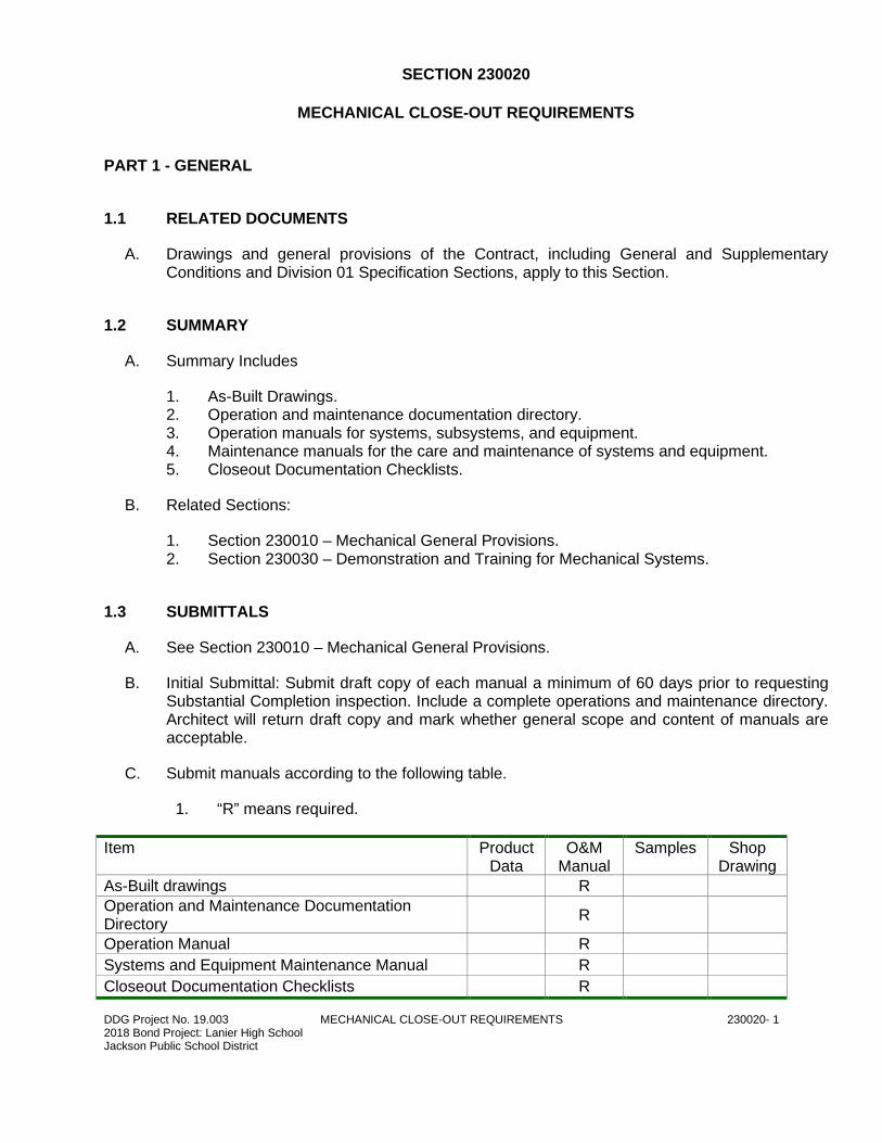
DDG Project No. 19.003 MECHANICAL CLOSE-OUT REQUIREMENTS 230020- 1 2018 Bond Project: Lanier High School Jackson Public School District
SECTION 230020
MECHANICAL CLOSE-OUT REQUIREMENTS
PART 1 - GENERAL
1.1 RELATED DOCUMENTS
A. Drawings and general provisions of the Contract, including General and Supplementary Conditions and Division 01 Specification Sections, apply to this Section.
1.2 SUMMARY
A. Summary Includes
1. As-Built Drawings. 2. Operation and maintenance documentation directory. 3. Operation manuals for systems, subsystems, and equipment. 4. Maintenance manuals for the care and maintenance of systems and equipment. 5. Closeout Documentation Checklists.
B. Related Sections:
1. Section 230010 – Mechanical General Provisions. 2. Section 230030 – Demonstration and Training for Mechanical Systems.
1.3 SUBMITTALS
A. See Section 230010 – Mechanical General Provisions.
B. Initial Submittal: Submit draft copy of each manual a minimum of 60 days prior to requesting Substantial Completion inspection. Include a complete operations and maintenance directory. Architect will return draft copy and mark whether general scope and content of manuals are acceptable.
C. Submit manuals according to the following table.
1. “R” means required.
Item Product Data
O&M Manual
Samples Shop Drawing
As-Built drawings R
Operation and Maintenance Documentation Directory
R
Operation Manual R
Systems and Equipment Maintenance Manual R
Closeout Documentation Checklists R
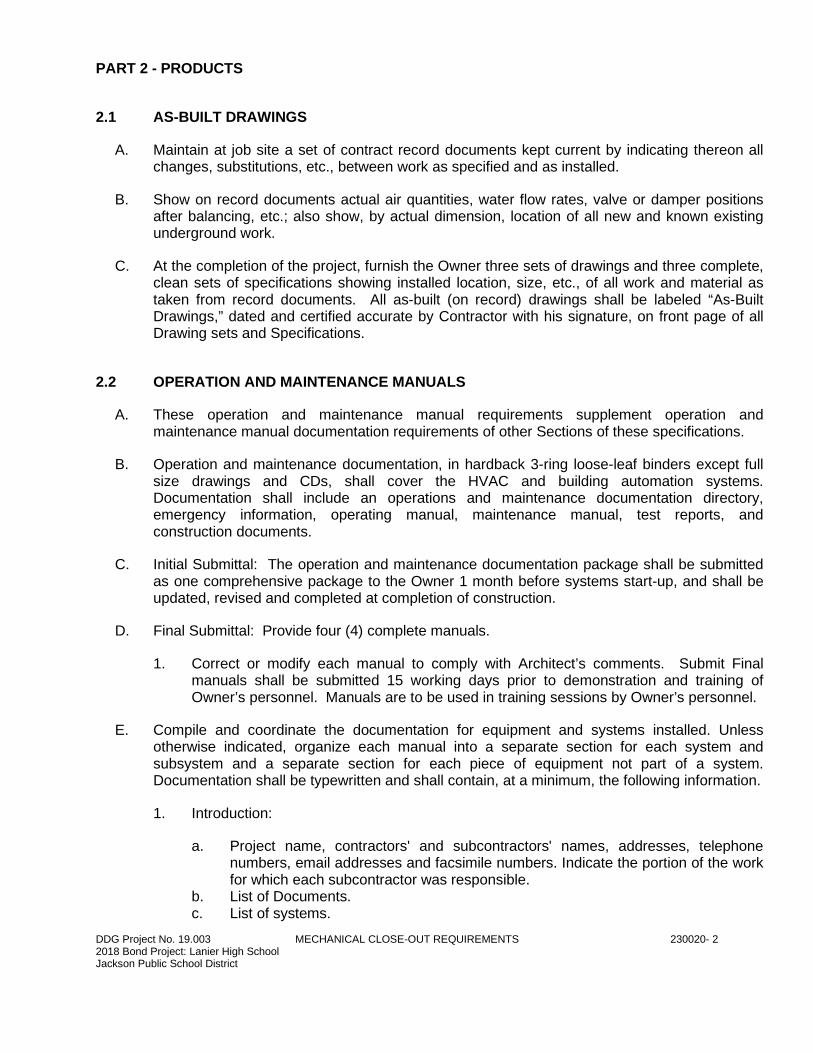
DDG Project No. 19.003 MECHANICAL CLOSE-OUT REQUIREMENTS 230020- 2 2018 Bond Project: Lanier High School Jackson Public School District
PART 2 - PRODUCTS
2.1 AS-BUILT DRAWINGS
A. Maintain at job site a set of contract record documents kept current by indicating thereon all changes, substitutions, etc., between work as specified and as installed.
B. Show on record documents actual air quantities, water flow rates, valve or damper positions after balancing, etc.; also show, by actual dimension, location of all new and known existing underground work.
C. At the completion of the project, furnish the Owner three sets of drawings and three complete, clean sets of specifications showing installed location, size, etc., of all work and material as taken from record documents. All as-built (on record) drawings shall be labeled “As-Built Drawings,” dated and certified accurate by Contractor with his signature, on front page of all Drawing sets and Specifications.
2.2 OPERATION AND MAINTENANCE MANUALS
A. These operation and maintenance manual requirements supplement operation and maintenance manual documentation requirements of other Sections of these specifications.
B. Operation and maintenance documentation, in hardback 3-ring loose-leaf binders except full size drawings and CDs, shall cover the HVAC and building automation systems. Documentation shall include an operations and maintenance documentation directory, emergency information, operating manual, maintenance manual, test reports, and construction documents.
C. Initial Submittal: The operation and maintenance documentation package shall be submitted as one comprehensive package to the Owner 1 month before systems start-up, and shall be updated, revised and completed at completion of construction.
D. Final Submittal: Provide four (4) complete manuals.
1. Correct or modify each manual to comply with Architect’s comments. Submit Final manuals shall be submitted 15 working days prior to demonstration and training of Owner’s personnel. Manuals are to be used in training sessions by Owner’s personnel.
E. Compile and coordinate the documentation for equipment and systems installed. Unless otherwise indicated, organize each manual into a separate section for each system and subsystem and a separate section for each piece of equipment not part of a system. Documentation shall be typewritten and shall contain, at a minimum, the following information.
1. Introduction:
a. Project name, contractors' and subcontractors' names, addresses, telephone numbers, email addresses and facsimile numbers. Indicate the portion of the work for which each subcontractor was responsible.
b. List of Documents. c. List of systems.
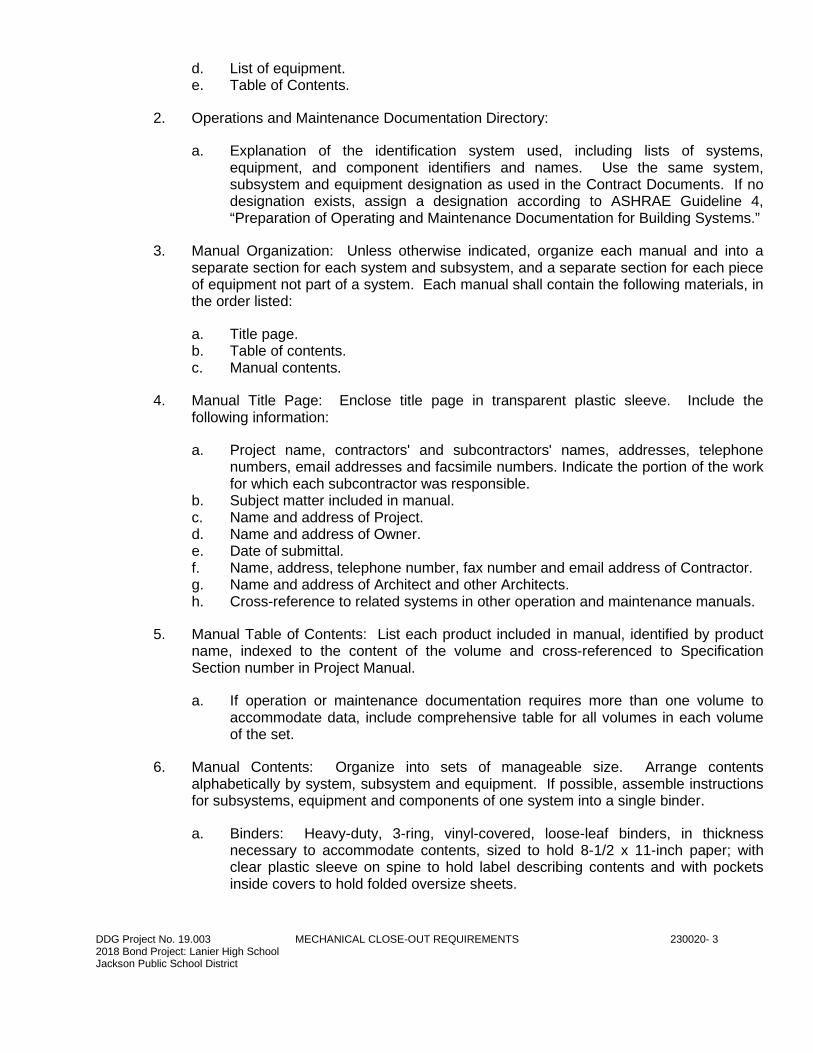
DDG Project No. 19.003 MECHANICAL CLOSE-OUT REQUIREMENTS 230020- 3 2018 Bond Project: Lanier High School Jackson Public School District
d. List of equipment. e. Table of Contents.
2. Operations and Maintenance Documentation Directory:
a. Explanation of the identification system used, including lists of systems, equipment, and component identifiers and names. Use the same system, subsystem and equipment designation as used in the Contract Documents. If no designation exists, assign a designation according to ASHRAE Guideline 4, “Preparation of Operating and Maintenance Documentation for Building Systems.”
3. Manual Organization: Unless otherwise indicated, organize each manual and into a separate section for each system and subsystem, and a separate section for each piece of equipment not part of a system. Each manual shall contain the following materials, in the order listed:
a. Title page. b. Table of contents. c. Manual contents.
4. Manual Title Page: Enclose title page in transparent plastic sleeve. Include the following information:
a. Project name, contractors' and subcontractors' names, addresses, telephone numbers, email addresses and facsimile numbers. Indicate the portion of the work for which each subcontractor was responsible.
b. Subject matter included in manual. c. Name and address of Project. d. Name and address of Owner. e. Date of submittal. f. Name, address, telephone number, fax number and email address of Contractor. g. Name and address of Architect and other Architects. h. Cross-reference to related systems in other operation and maintenance manuals.
5. Manual Table of Contents: List each product included in manual, identified by product name, indexed to the content of the volume and cross-referenced to Specification Section number in Project Manual.
a. If operation or maintenance documentation requires more than one volume to accommodate data, include comprehensive table for all volumes in each volume of the set.
6. Manual Contents: Organize into sets of manageable size. Arrange contents alphabetically by system, subsystem and equipment. If possible, assemble instructions for subsystems, equipment and components of one system into a single binder.
a. Binders: Heavy-duty, 3-ring, vinyl-covered, loose-leaf binders, in thickness necessary to accommodate contents, sized to hold 8-1/2 x 11-inch paper; with clear plastic sleeve on spine to hold label describing contents and with pockets inside covers to hold folded oversize sheets.
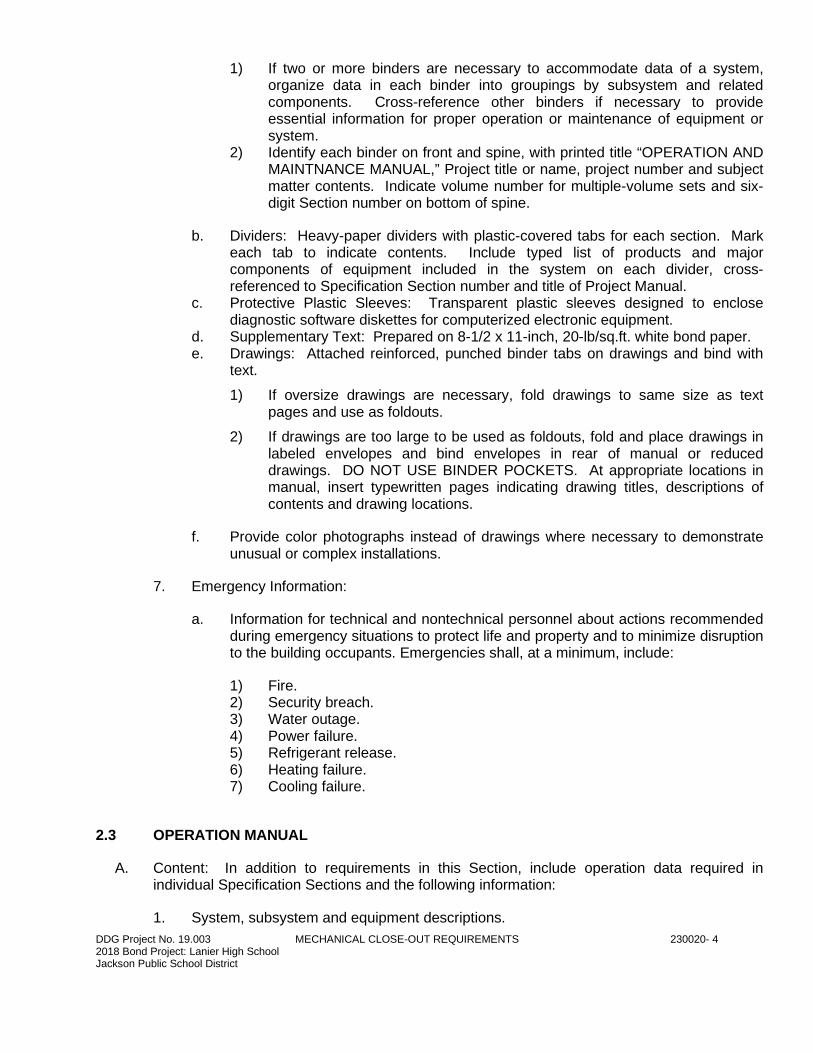
DDG Project No. 19.003 MECHANICAL CLOSE-OUT REQUIREMENTS 230020- 4 2018 Bond Project: Lanier High School Jackson Public School District
1) If two or more binders are necessary to accommodate data of a system, organize data in each binder into groupings by subsystem and related components. Cross-reference other binders if necessary to provide essential information for proper operation or maintenance of equipment or system.
2) Identify each binder on front and spine, with printed title “OPERATION AND MAINTNANCE MANUAL,” Project title or name, project number and subject matter contents. Indicate volume number for multiple-volume sets and six-digit Section number on bottom of spine.
b. Dividers: Heavy-paper dividers with plastic-covered tabs for each section. Mark each tab to indicate contents. Include typed list of products and major components of equipment included in the system on each divider, cross-referenced to Specification Section number and title of Project Manual.
c. Protective Plastic Sleeves: Transparent plastic sleeves designed to enclose diagnostic software diskettes for computerized electronic equipment.
d. Supplementary Text: Prepared on 8-1/2 x 11-inch, 20-lb/sq.ft. white bond paper. e. Drawings: Attached reinforced, punched binder tabs on drawings and bind with
text.
1) If oversize drawings are necessary, fold drawings to same size as text pages and use as foldouts.
2) If drawings are too large to be used as foldouts, fold and place drawings in labeled envelopes and bind envelopes in rear of manual or reduced drawings. DO NOT USE BINDER POCKETS. At appropriate locations in manual, insert typewritten pages indicating drawing titles, descriptions of contents and drawing locations.
f. Provide color photographs instead of drawings where necessary to demonstrate unusual or complex installations.
7. Emergency Information:
a. Information for technical and nontechnical personnel about actions recommended during emergency situations to protect life and property and to minimize disruption to the building occupants. Emergencies shall, at a minimum, include:
1) Fire. 2) Security breach. 3) Water outage. 4) Power failure. 5) Refrigerant release. 6) Heating failure. 7) Cooling failure.
2.3 OPERATION MANUAL
A. Content: In addition to requirements in this Section, include operation data required in individual Specification Sections and the following information:
1. System, subsystem and equipment descriptions.
DDG Project No. 19.003 MECHANICAL CLOSE-OUT REQUIREMENTS 230020- 5 2018 Bond Project: Lanier High School Jackson Public School District
2. Performance and design criteria if Contractor is delegated design responsibility. 3. Operating standards. 4. Operating procedures. 5. Operating logs. 6. Wiring diagrams. 7. Control diagrams. 8. Piped system diagrams. 9. Valve tag lists. 10. Precautions against improper use. 11. License requirements including inspection and renewal dates.
B. Descriptions: Include the following:
1. Product name and model number. 2. Manufacturer’s name. 3. Equipment identification with serial number of each component. 4. Equipment function. 5. Operating characteristics. 6. Limiting conditions. 7. Performance curves for pumps, fans and heat exchangers. 8. Engineering data and tests. 9. Complete nomenclature and number of replacement parts.
C. Operating Procedures: Include the following, as applicable:
1. Startup procedures. 2. Equipment of system break-in procedures. 3. Routine and normal operating instructions. 4. Regulation and control procedures. 5. Instructions on stopping. 6. Normal shutdown instructions. 7. Seasonal and weekend operating instructions. 8. Required sequences for electric or electronic systems. 9. Special operating instructions and procedures.
D. Systems and Equipment Controls: Describe the sequence of operation and diagram controls as installed.
E. Piped Systems: Diagram piping as installed and identify color-coding where required for identification.
2.4 SYSTEMS AND EQUIPMENT MAINTENANCE MANUAL
A. Content: For each system, subsystem and piece of equipment not part of a system, include source information, product information, maintenance procedures, repair materials, warranty information and bond information as described below.
B. Source Information: List each product included in manual, identified by product name and arranged to match manual’s table of contents. For each product, list name, address and telephone number of Installer or supplier and maintenance service agent. Cross-reference Specification Section number and title in Project Manual.
DDG Project No. 19.003 MECHANICAL CLOSE-OUT REQUIREMENTS 230020- 6 2018 Bond Project: Lanier High School Jackson Public School District
C. Manufacturer’s Maintenance Documentation: Manufacturer’s maintenance documentation including the following information for each component part or piece of equipment:
1. Standard printed maintenance instructions and bulletins. 2. Drawings, diagrams and instructions required for maintenance including disassembly
and component removal, replacement and assembly. 3. Identification and nomenclature of parts and components. 4. List of items recommended to be stocked as spare parts.
D. Maintenance Procedures: Include the following information and items that detail essential maintenance procedures:
1. Test and inspection instructions. 2. Troubleshooting guide. 3. Precautions against improper maintenance. 4. Disassembly: component removal, repair and replacement and reassembly
Instructions. 5. Aligning, adjusting and checking instructions. 6. Manufacturer’s demonstration and training videotape or DVD, if available.
E. Maintenance and Service Schedule: Include service and lubrication requirements, list of required lubricants for equipment and separate schedules for preventative and routine maintenance and service with standard time allotment.
1. Scheduled Maintenance and Service: Tabulate actions for daily, weekly, monthly, quarterly, semiannual and annual frequencies.
2. Maintenance and Service Record: Include manufacturer’s forms for recording maintenance.
F. Spare Parts List and Source Information: Include lists of replacement and repair parts, with parts identified and cross-referenced to manufacturer’s maintenance documentation and local sources of maintenance materials and related services.
G. Maintenance Service Contracts: Include copies of maintenance agreements with name and telephone number of service agent.
H. Warranties and Bonds: Include copies of executed warranties and bonds and lists of circumstances and conditions that would affect validity of warranties and bonds.
1. Include procedures to follow and required notifications for warranty claims.
NOTE: Where manuals contain manufacturer’s standard printed data, include only sheets pertinent to product or component installed. Mark each sheet to identify each product or component incorporated into the Work. If data includes more than one item in a tabular format, identify each item using appropriate references from the Contract Documents. Identify data applicable to the Work and delete references to information not applicable.
DDG Project No. 19.003 MECHANICAL CLOSE-OUT REQUIREMENTS 230020- 7 2018 Bond Project: Lanier High School Jackson Public School District
2.5 CLOSEOUT DOCUMENTATION
A. Seven days prior to requesting a final inspection, the Contractor shall submit all O&M and closeout documentation to the Architect, to be submitted to the Owner at the end of the project.
B. The checklist herein shall be utilized for compiling documentation and shall be included behind front cover of O&M manuals.
C. Contractor shall initial and date each line item once completed and shall email a copy of the completed checklist to the Architect prior to final inspection request.
PART 3 - EXECUTION
3.1 MANUAL PREPARATION
A. Operation and Maintenance Documentation Directory: Prepare a separate manual that provides an organized reference to emergency, operation, and maintenance manuals.
B. Assembly a complete set of the following manuals indicating procedures for each.
1. Product maintenance manual. 2. Operations and maintenance manual.
C. Manufacturer’s Data: When manuals contain manufacturer’s standard printed data, include only sheets pertinent to product or component installed. Mark each sheet to identify each product or component incorporated into the Work. If data include more than one item in a tabular format, identify each item using appropriate references from the Contract Documents. Identify data applicable to the Work and delete references to information not applicable.
1. Prepare supplementary text if manufacturers’ standard printed data are not available and where the information is necessary for proper operation and maintenance of equipment or systems.
D. Drawings: Prepare drawings supplementing manufacturer’s printed data to illustrate the relationship of component parts of equipment and systems and to illustrate control sequences and flow diagrams. Coordinate these drawings with information contained in Record Drawings to ensure correct illustration of completed installation.
1. Do not use original Project Record Drawings as part of operation and maintenance manuals.
3.2 CLOSEOUT DOCUMENTATION CHECKLIST
A. Closeout Documentation Checklists included:
1. Division 22 – Plumbing.

DDG Project No. 19.003 MECHANICAL CLOSE-OUT REQUIREMENTS 230020- 8 2018 Bond Project: Lanier High School Jackson Public School District
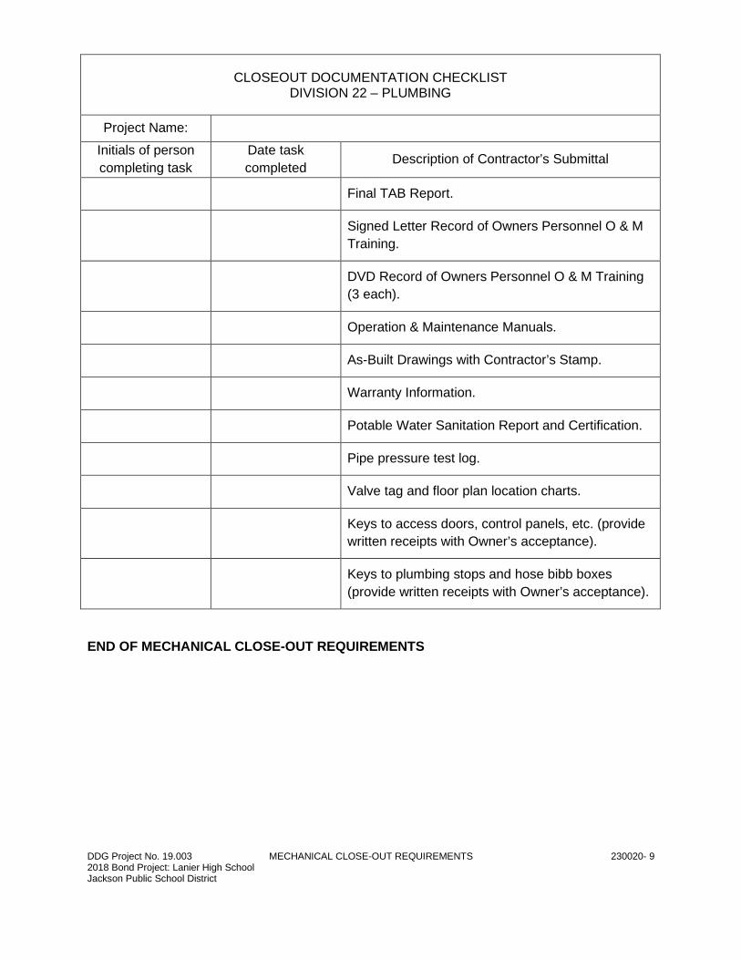
DDG Project No. 19.003 MECHANICAL CLOSE-OUT REQUIREMENTS 230020- 9 2018 Bond Project: Lanier High School Jackson Public School District
CLOSEOUT DOCUMENTATION CHECKLIST DIVISION 22 – PLUMBING
Project Name:
Initials of person
completing task
Date task
completed Description of Contractor’s Submittal
Final TAB Report.
Signed Letter Record of Owners Personnel O & M
Training.
DVD Record of Owners Personnel O & M Training
(3 each).
Operation & Maintenance Manuals.
As-Built Drawings with Contractor’s Stamp.
Warranty Information.
Potable Water Sanitation Report and Certification.
Pipe pressure test log.
Valve tag and floor plan location charts.
Keys to access doors, control panels, etc. (provide
written receipts with Owner’s acceptance).
Keys to plumbing stops and hose bibb boxes
(provide written receipts with Owner’s acceptance).
END OF MECHANICAL CLOSE-OUT REQUIREMENTS
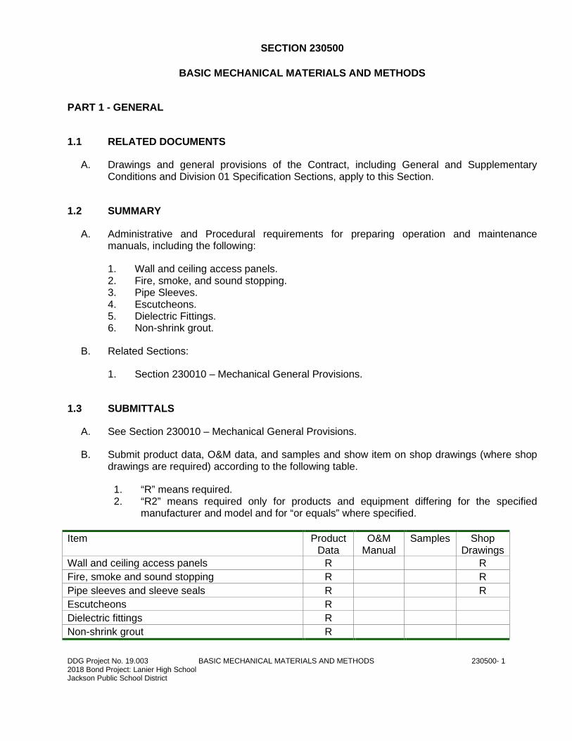
DDG Project No. 19.003 BASIC MECHANICAL MATERIALS AND METHODS 230500- 1 2018 Bond Project: Lanier High School Jackson Public School District
SECTION 230500
BASIC MECHANICAL MATERIALS AND METHODS
PART 1 - GENERAL
1.1 RELATED DOCUMENTS
A. Drawings and general provisions of the Contract, including General and Supplementary Conditions and Division 01 Specification Sections, apply to this Section.
1.2 SUMMARY
A. Administrative and Procedural requirements for preparing operation and maintenance manuals, including the following:
1. Wall and ceiling access panels. 2. Fire, smoke, and sound stopping. 3. Pipe Sleeves. 4. Escutcheons. 5. Dielectric Fittings. 6. Non-shrink grout.
B. Related Sections:
1. Section 230010 – Mechanical General Provisions.
1.3 SUBMITTALS
A. See Section 230010 – Mechanical General Provisions.
B. Submit product data, O&M data, and samples and show item on shop drawings (where shop drawings are required) according to the following table.
1. “R” means required. 2. “R2” means required only for products and equipment differing for the specified
manufacturer and model and for “or equals” where specified.
Item Product Data
O&M Manual
Samples Shop Drawings
Wall and ceiling access panels R R
Fire, smoke and sound stopping R R
Pipe sleeves and sleeve seals R R
Escutcheons R
Dielectric fittings R
Non-shrink grout R
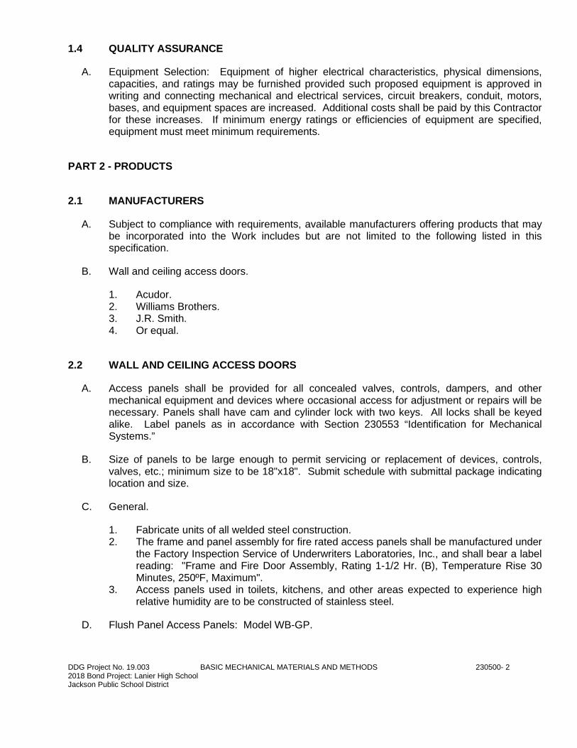
DDG Project No. 19.003 BASIC MECHANICAL MATERIALS AND METHODS 230500- 2 2018 Bond Project: Lanier High School Jackson Public School District
1.4 QUALITY ASSURANCE
A. Equipment Selection: Equipment of higher electrical characteristics, physical dimensions, capacities, and ratings may be furnished provided such proposed equipment is approved in writing and connecting mechanical and electrical services, circuit breakers, conduit, motors, bases, and equipment spaces are increased. Additional costs shall be paid by this Contractor for these increases. If minimum energy ratings or efficiencies of equipment are specified, equipment must meet minimum requirements.
PART 2 - PRODUCTS
2.1 MANUFACTURERS
A. Subject to compliance with requirements, available manufacturers offering products that may be incorporated into the Work includes but are not limited to the following listed in this specification.
B. Wall and ceiling access doors.
1. Acudor. 2. Williams Brothers. 3. J.R. Smith. 4. Or equal.
2.2 WALL AND CEILING ACCESS DOORS
A. Access panels shall be provided for all concealed valves, controls, dampers, and other mechanical equipment and devices where occasional access for adjustment or repairs will be necessary. Panels shall have cam and cylinder lock with two keys. All locks shall be keyed alike. Label panels as in accordance with Section 230553 “Identification for Mechanical Systems.”
B. Size of panels to be large enough to permit servicing or replacement of devices, controls, valves, etc.; minimum size to be 18"x18". Submit schedule with submittal package indicating location and size.
C. General.
1. Fabricate units of all welded steel construction. 2. The frame and panel assembly for fire rated access panels shall be manufactured under
the Factory Inspection Service of Underwriters Laboratories, Inc., and shall bear a label reading: "Frame and Fire Door Assembly, Rating 1-1/2 Hr. (B), Temperature Rise 30 Minutes, 250ºF, Maximum".
3. Access panels used in toilets, kitchens, and other areas expected to experience high relative humidity are to be constructed of stainless steel.
D. Flush Panel Access Panels: Model WB-GP.
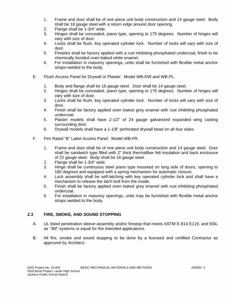
DDG Project No. 19.003 BASIC MECHANICAL MATERIALS AND METHODS 230500- 3 2018 Bond Project: Lanier High School Jackson Public School District
1. Frame and door shall be of one piece unit body construction and 14 gauge steel. Body shall be 18 gauge steel with a return edge around door opening.
2. Flange shall be 1-3/4” wide. 3. Hinges shall be concealed, piano type, opening to 175 degrees. Number of hinges will
vary with size of door. 4. Locks shall be flush, key operated cylinder lock. Number of locks will vary with size of
door. 5. Finishes shall be factory applied with a rust inhibiting phosphated undercoat; finish to be
chemically bonded oven baked white enamel. 6. For installation in masonry openings, units shall be furnished with flexible metal anchor
straps welded to the body.
E. Flush Access Panel for Drywall or Plaster: Model WB-DW and WB-PL.
1. Body and flange shall be 16 gauge steel. Door shall be 14 gauge steel. 2. Hinges shall be concealed, piano type, opening to 175 degrees. Number of hinges will
vary with size of door. 3. Locks shall be flush, key operated cylinder lock. Number of locks will vary with size of
door. 4. Finish shall be factory applied oven baked grey enamel with rust inhibiting phosphated
undercoat. 5. Plaster models shall have 2-1/2” of 24 gauge galvanized expanded wing casting
surrounding door. 6. Drywall models shall have a 1-1/8” perforated drywall bead on all four sides.
F. Fire Rated “B” Label Access Panel: Model WB-FR.
1. Frame and door shall be of one piece unit body construction and 14 gauge steel. Door shall be sandwich type filled with 2" thick thermafiber felt insulation and back enclosure of 22 gauge steel. Body shall be 16 gauge steel.
2. Flange shall be 1-3/4” wide. 3. Hinge shall be continuous steel piano type mounted on long side of doors, opening to
180 degrees and equipped with a spring mechanism for automatic closure. 4. Lock assembly shall be self-latching with key operated cylinder lock and shall have a
mechanism to release the latch bolt from the inside. 5. Finish shall be factory applied oven baked grey enamel with rust inhibiting phosphated
undercoat. 6. For installation in masonry openings, units may be furnished with flexible metal anchor
straps welded to the body.
2.3 FIRE, SMOKE, AND SOUND STOPPING
A. UL listed penetration sleeve assembly and/or firestop that meets ASTM E-814 E119, and E84, as "3M" systems or equal for the intended applications.
B. All fire, smoke and sound stopping to be done by a licensed and certified Contractor as approved by Architect.
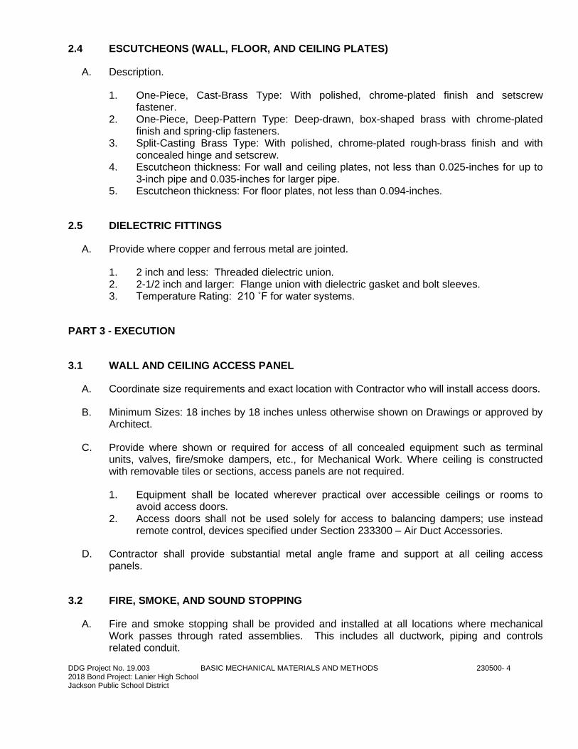
DDG Project No. 19.003 BASIC MECHANICAL MATERIALS AND METHODS 230500- 4 2018 Bond Project: Lanier High School Jackson Public School District
2.4 ESCUTCHEONS (WALL, FLOOR, AND CEILING PLATES)
A. Description.
1. One-Piece, Cast-Brass Type: With polished, chrome-plated finish and setscrew fastener.
2. One-Piece, Deep-Pattern Type: Deep-drawn, box-shaped brass with chrome-plated finish and spring-clip fasteners.
3. Split-Casting Brass Type: With polished, chrome-plated rough-brass finish and with concealed hinge and setscrew.
4. Escutcheon thickness: For wall and ceiling plates, not less than 0.025-inches for up to 3-inch pipe and 0.035-inches for larger pipe.
5. Escutcheon thickness: For floor plates, not less than 0.094-inches.
2.5 DIELECTRIC FITTINGS
A. Provide where copper and ferrous metal are jointed.
1. 2 inch and less: Threaded dielectric union. 2. 2-1/2 inch and larger: Flange union with dielectric gasket and bolt sleeves. 3. Temperature Rating: 210 ˚F for water systems.
PART 3 - EXECUTION
3.1 WALL AND CEILING ACCESS PANEL
A. Coordinate size requirements and exact location with Contractor who will install access doors.
B. Minimum Sizes: 18 inches by 18 inches unless otherwise shown on Drawings or approved by Architect.
C. Provide where shown or required for access of all concealed equipment such as terminal units, valves, fire/smoke dampers, etc., for Mechanical Work. Where ceiling is constructed with removable tiles or sections, access panels are not required.
1. Equipment shall be located wherever practical over accessible ceilings or rooms to avoid access doors.
2. Access doors shall not be used solely for access to balancing dampers; use instead remote control, devices specified under Section 233300 – Air Duct Accessories.
D. Contractor shall provide substantial metal angle frame and support at all ceiling access panels.
3.2 FIRE, SMOKE, AND SOUND STOPPING
A. Fire and smoke stopping shall be provided and installed at all locations where mechanical Work passes through rated assemblies. This includes all ductwork, piping and controls related conduit.
DDG Project No. 19.003 BASIC MECHANICAL MATERIALS AND METHODS 230500- 5 2018 Bond Project: Lanier High School Jackson Public School District
B. Penetrations in “sound-rated” walls shall be similarly acoustically sealed, both sides of wall with caulk or other approved material. New and existing walls extending to the roof/floor structure above are considered sound walls.
3.3 ESCUTCHEONS
A. Install pipe escutcheons for exposed pipe penetrations of concrete and masonry walls, wall board partitions, suspended ceilings, etc.
B. Inside diameter shall fit around insulation or around pipe when not insulated; outside diameter shall cover sleeve.
C. Use plates that fit tight around insulation or pipes when not insulated.
D. Plates shall cover openings around pipes/insulation and cover the entire pipe sleeve projection. Use deep pattern escutcheons where required to completely conceal protruding fittings and sleeves.
3.4 DIELECTRIC FITTINGS
A. Wet Piping Systems: Install dielectric coupling, unions, and nipple fittings to connect piping materials of dissimilar metals.
3.5 GROUTING
A. Install nonmetallic, non-shrink, grout for mechanical equipment base bearing surfaces, pump and other equipment base plates, pipe support base plates, and anchors. Mix grout according to manufacturer's written instructions.
B. Clean surfaces that will come into contact with grout.
C. Provide forms as required for placement of grout.
D. Place grout, completely filling equipment bases and pipe support base plates.
E. Place grout around anchors.
F. Cure placed grout according to manufacturer's written instructions.
3.6 CUTTING AND PATCHING
A. Do not cut into any major structural element without written approval of the Architect.
B. Cut required openings through existing masonry or reinforced concrete with diamond core drills. Use of pneumatic hammer type drills, impact type electric drills, and hand or manual hammer type drills, will be permitted only with approval of the Architect. Locate openings that will least affect structural slabs, columns, ribs or beams. Refer to the Architect for determination of proper design for openings through structural sections and opening layouts
DDG Project No. 19.003 BASIC MECHANICAL MATERIALS AND METHODS 230500- 6 2018 Bond Project: Lanier High School Jackson Public School District
for approval prior to cutting or drilling into structure. After Architect’s approval, carefully cut openings through construction no larger than absolutely necessary for the required installation.
C. Patching:
1. Shall be of quality and appearance matching the existing construction. 2. Contractor shall restore all services and construction that remains in use, to its condition
prior to Work performed as part of this contract.
END OF BASIC MECHANICAL MATERIALS AND METHODS
DDG Project No. 19.003 VALVES 230523- 1 2018 Bond Project: Lanier High School Jackson Public School District
SECTION 230523
VALVES
PART 1 - GENERAL
1.1 RELATED DOCUMENTS
A. Drawings and general provisions of the Contract, including General and Supplementary Conditions and Division 01 Specification Sections, apply to this Section.
1.2 SUMMARY
A. Work Included in This Section: Materials, equipment, fabrication, installation and tests in conformity with applicable codes and authorities having jurisdiction for the following:
1. Service valves in plumbing systems. 2. Balancing valves. 3. Check valves.
B. Related Sections:
1. Section 221116 – Domestic Water Piping.
1.3 QUALITY ASSURANCE
A. Provide valves with manufacturer's name and pressure rating clearly marked on outside of body.
1.4 SUBMITTALS
A. See Section 230010 Mechanical General Provisions.
B. Submit product data, O&M data, and samples and show item on shop and coordination drawings according to the following table.
1. “R” means required. 2. “R2” means required only for products and equipment differing for the specified
manufacturer and model and for “or equals” where specified.
Item Product Data
O&M Manual
Samples Shop Drawing
Valves, all types R R R
DDG Project No. 19.003 VALVES 230523- 2 2018 Bond Project: Lanier High School Jackson Public School District
Valve accessories (handle extensions, operators, etc.)
R
Manual and automatic air vents R R
Pressure/temperature test plug R R
PART 2 - PRODUCTS
2.1 MANUFACTURERS
A. Named manufacturer model numbers used as example of item and establish minimum level of quality and minimum standard options. Equivalent models of listed manufacturers are acceptable.
B. Ball valves.
1. Nibco Inc. 2. Crane Company. 3. De Zurik Corporation. 4. Or equal.
2.2 GENERAL
A. Where possible, provide valves of same manufacturer for all Mechanical Sections per products in this Section.
B. For copper tubing provide solder-joint valves, flare fittings, or IPS-to-copper adaptor, sized for use with tubing and respective valve.
C. For flanged valves, provide streamline companion flanges, ANSI B16.5, 1988 150 class pounds per square inch.
1. 255 pounds per square inch water on gage (WOG) at 150 degree Fahrenheit. 2. 225 pounds per square inch water on gage (WOG) at 250 degree Fahrenheit
unless indicated otherwise.
D. Provide valves rated not less than 125 pounds per square inch steam working pressure, unless indicated otherwise.
E. Provide valve materials suitable for service and temperature of respective systems, especially with respect to discs, plugs, balls, linings, gaskets, and lubricants of globe valves, plug cocks, ball valves, etc.
F. Valves in Insulated Piping: With 2 inch (minimum, greater if insulation thickness is greater than 2 inches) stem extensions and the following features:
1. Ball Valves: With extended operating handle of non-thermal-conductive material and protective sleeve that allows operation of valve without breaking the vapor
DDG Project No. 19.003 VALVES 230523- 3 2018 Bond Project: Lanier High School Jackson Public School District
seal or disturbing insulation and memory stops that are fully adjustable after insulation is applied. Nibco Nib-seal handle extension or equal.
2. Butterfly Valves: With extended neck.
2.3 BALL VALVES
A. 2-1/2 inches and smaller.
1. Two piece body, bronze ASTM B584 C84400. 2. 316 stainless steel stem and ball. 3. PTFE Seat. 4. Full Port 1/2 to 1 inch; Standard Port 1-1/4 and larger. 5. 600 pounds per square inch at 100 degree F, 125 pounds per square inch
saturated steam. 6. Infinite throttling handle with memory stop. 7. Nibco 585-70-66 or equal. Nibco 580-70-66 or equal may be used for 1-1/4 inch
and larger.
PART 3 - EXECUTION
3.1 INSTALLATION
A. Coordinate with work of other trades.
B. Install valves in accordance with manufacturer’s written installation instructions.
C. Provide valves as shown on drawings and provide shutoff valves around all equipment whether shown with valves on drawings or not.
D. Provide all valves (except control valves), strainers, and check valves of same size as the pipes in which they are installed unless otherwise indicated.
E. Pressure rating of valves same as piping in which installed.
F. Install valves with stems upright or horizontal, not inverted.
G. Install valves with cast directional arrows in direction of flow.
H. Support line valves at the valve in addition to regularly spaced pipe supports shown and specified.
I. Provide blow-down ball valves and hose adaptors at strainers, air separators, tanks, pipe traps, equipment drains, etc. of same size as strainer blow-off connection.
J. Provide drain valves at main shut-off valves, low points of piping and apparatus.
K. Provide extended valve stems to clear insulation on insulated valves.
DDG Project No. 19.003 VALVES 230523- 4 2018 Bond Project: Lanier High School Jackson Public School District
L. Locate wheel handles to clear obstructions with hand.
M. Install valves only in accessible locations.
N. Wherever possible, install valves accessible from floor level.
O. Locate equipment shut-off valves to be accessible without climbing over equipment.
P. Provide operating handles for all valves and cocks without integral operators, unless otherwise noted. Provide adequate clearance for easy operation.
Q. Provide ball valves to isolate shock absorbers.
R. Provide open-ended line valves with plugs or blind flanges.
3.2 VALVE APPLICATIONS
A. Valves shall be limited to the applications listed below. Where this section disagrees with drawings, obtain clarification from Architect and provide as directed by the Architect at no additional cost to the Owner.
B. Ball valves:
1. Use in domestic water piping 2-1/2 inches and smaller.
3.3 FIELD QUALITY CONTROL
A. Test operate valves from closed-to-open-to-closed position while valve is under test pressure.
B. Test automatic valves including solenoid valves, expansion valves, water regulating valves, pressure reducing valves, pressure relief valves, safety valves and temperature and pressure relief valves for proper operation at settings indicated.
C. Insure that valves are field checked for packing and lubricant and that disc is for service intended. Replace leaking packing at no additional cost to the Owner. Service valves which do not operate smoothly and properly with suitable lubricant before placing in operation at no additional cost to the Owner.
3.4 INSPECTION & COMPLETION
A. Verify that adequate clearance between valves and adjacent walls or equipment is available to permit maintenance and repairs.
B. Verify valve set for normal operation.
END OF VALVES
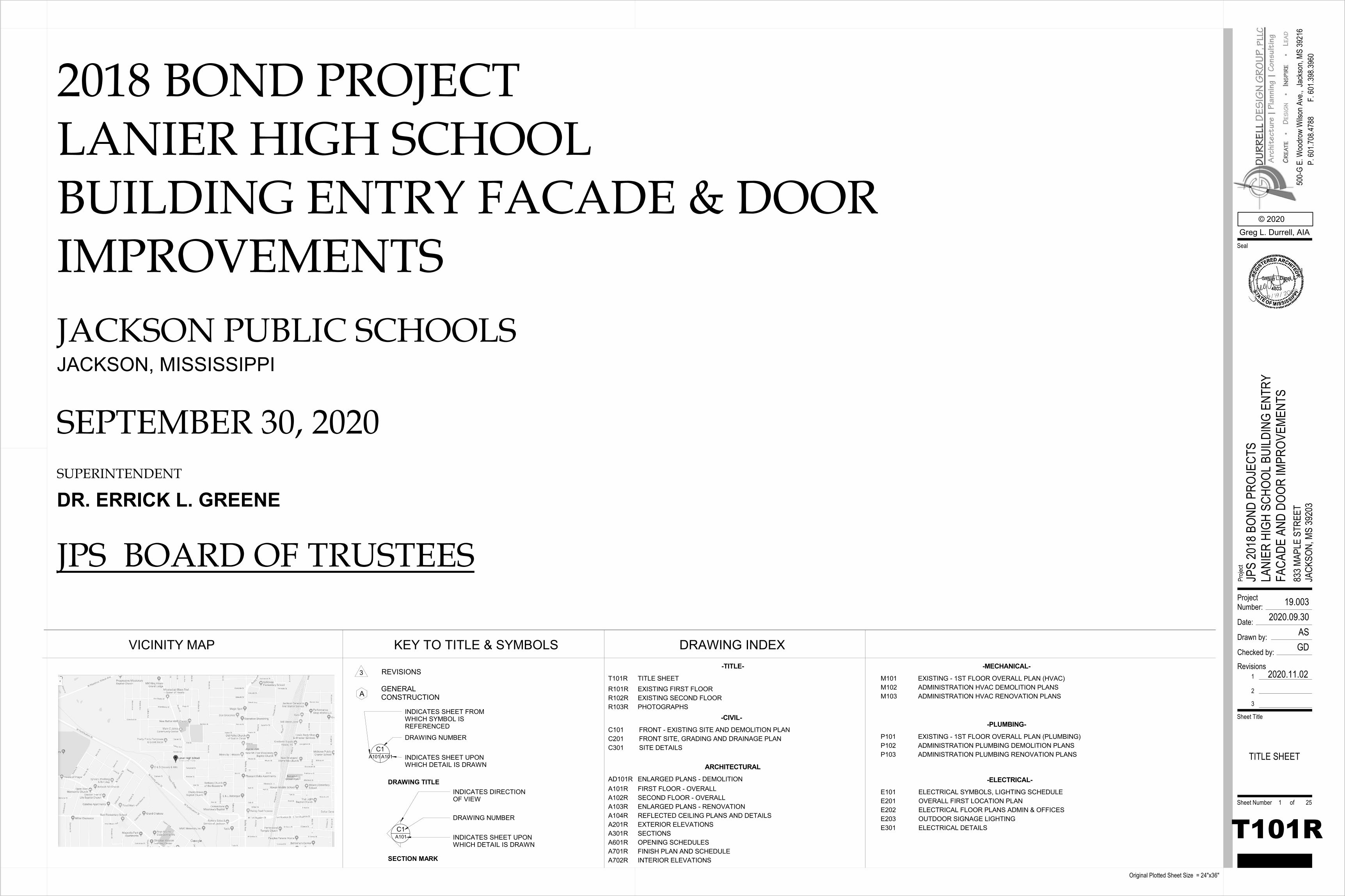
2018 BOND PROJECTLANIER HIGH SCHOOLBUILDING ENTRY FACADE & DOOR IMPROVEMENTS
VICINITY MAP DRAWING INDEXKEY TO TITLE & SYMBOLS
DRAWING TITLE
A
3 REVISIONS
CONSTRUCTIONGENERAL
INDICATES SHEET FROM WHICH SYMBOL IS REFERENCED
DRAWING NUMBER
INDICATES SHEET UPON WHICH DETAIL IS DRAWN
C1A101A101
SECTION MARK
DRAWING NUMBER
INDICATES SHEET UPON WHICH DETAIL IS DRAWN
INDICATES DIRECTION OF VIEW
-TITLE-
T101R TITLE SHEET
JPS BOARD OF TRUSTEES
JACKSON PUBLIC SCHOOLS
DR. ERRICK L. GREENESUPERINTENDENT
SEPTEMBER 30, 2020
JACKSON, MISSISSIPPI
ProjectNumber:
Date:
Drawn by:
Checked by:
Sheet Number of
Sheet Title
Proje
ct
Original Plotted Sheet Size = 24"x36"
© 2020Greg L. Durrell, AIA
500-
G E.
Woo
drow
Wils
on A
ve.,
Seal
Jack
son,
MS 39
216
P. 60
1.708
.4788
F. 60
1.398
.3960
Revisions1
2
3
2020.11.02
19.0032020.09.30
ASGD
T101R
JPS
2018
BON
D PR
OJEC
TSLA
NIER
HIG
H SC
HOOL
BUI
LDIN
G EN
TRY
FACA
DE A
ND D
OOR
IMPR
OVEM
ENTS
833 M
APLE
STR
EET
JACK
SON,
MS
3920
3
TITLE SHEET
1 25
A101R FIRST FLOOR - OVERALLA102R SECOND FLOOR - OVERALLA103R ENLARGED PLANS - RENOVATIONA104R REFLECTED CEILING PLANS AND DETAILSA201R EXTERIOR ELEVATIONSA301R SECTIONSA601R OPENING SCHEDULESA701R FINISH PLAN AND SCHEDULEA702R INTERIOR ELEVATIONS
-ELECTRICAL-E101 ELECTRICAL SYMBOLS, LIGHTING SCHEDULEE201 OVERALL FIRST LOCATION PLANE202 ELECTRICAL FLOOR PLANS ADMIN & OFFICESE203 OUTDOOR SIGNAGE LIGHTINGE301 ELECTRICAL DETAILS
-CIVIL-C101 FRONT - EXISTING SITE AND DEMOLITION PLANC201 FRONT SITE, GRADING AND DRAINAGE PLANC301 SITE DETAILS
-MECHANICAL-
M101 EXISTING - 1ST FLOOR OVERALL PLAN (HVAC)M102 ADMINISTRATION HVAC DEMOLITION PLANSM103 ADMINISTRATION HVAC RENOVATION PLANS
-PLUMBING-
P101 EXISTING - 1ST FLOOR OVERALL PLAN (PLUMBING)P102 ADMINISTRATION PLUMBING DEMOLITION PLANSP103 ADMINISTRATION PLUMBING RENOVATION PLANS
R101R EXISTING FIRST FLOORR102R EXISTING SECOND FLOORR103R PHOTOGRAPHS
ARCHITECTURALAD101R ENLARGED PLANS - DEMOLITION
C1A101
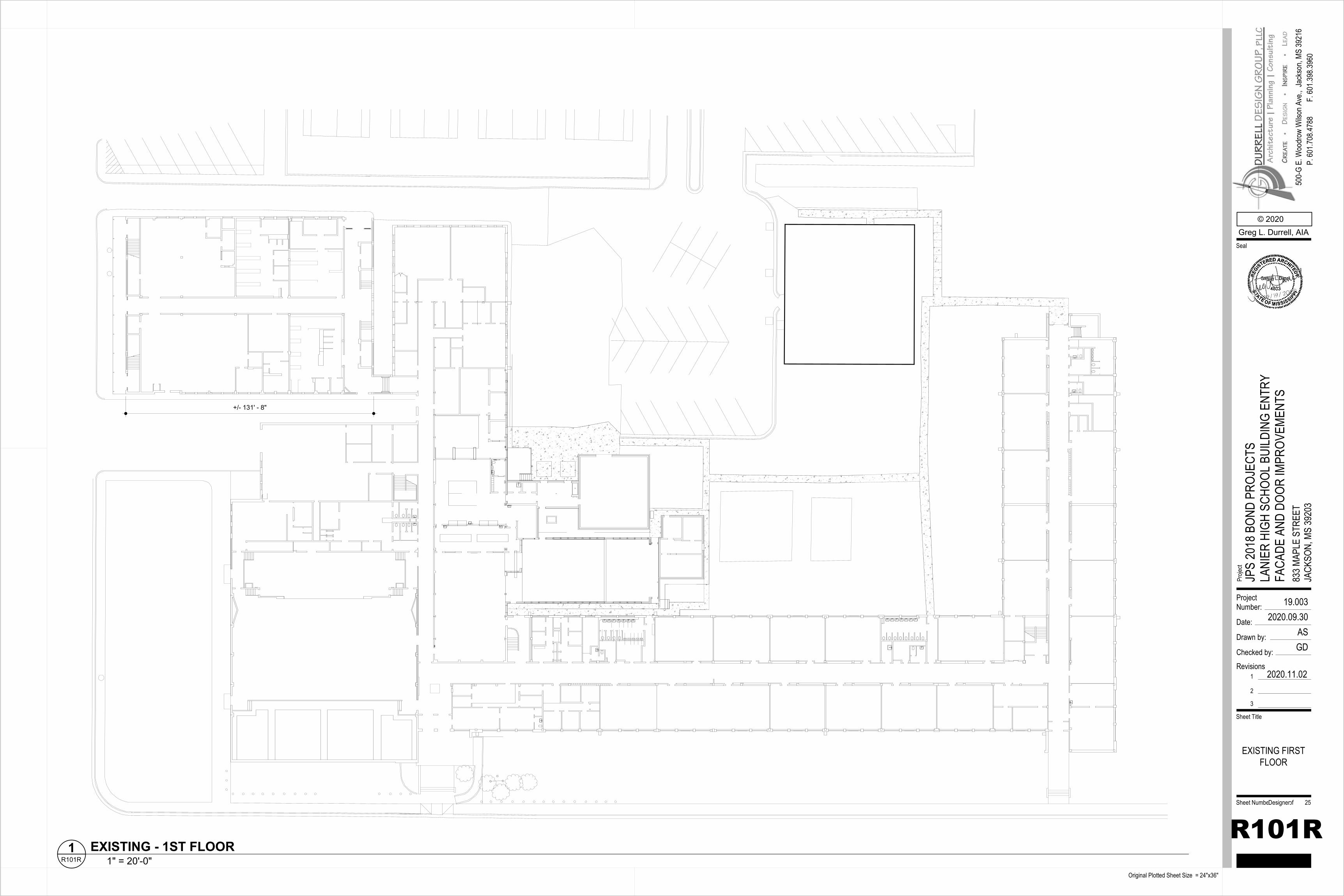
+/- 131' - 8"
ProjectNumber:
Date:
Drawn by:
Checked by:
Sheet Number of
Sheet Title
Proje
ct
Original Plotted Sheet Size = 24"x36"
© 2020Greg L. Durrell, AIA
500-
G E.
Woo
drow
Wils
on A
ve.,
Seal
Jack
son,
MS 39
216
P. 60
1.708
.4788
F. 60
1.398
.3960
Revisions1
2
3
2020.11.02
19.0032020.09.30
ASGD
R101R
JPS
2018
BON
D PR
OJEC
TSLA
NIER
HIG
H SC
HOOL
BUI
LDIN
G EN
TRY
FACA
DE A
ND D
OOR
IMPR
OVEM
ENTS
833 M
APLE
STR
EET
JACK
SON,
MS
3920
3
EXISTING FIRSTFLOOR
Designer 25
1" = 20'-0"R101R1 EXISTING - 1ST FLOOR
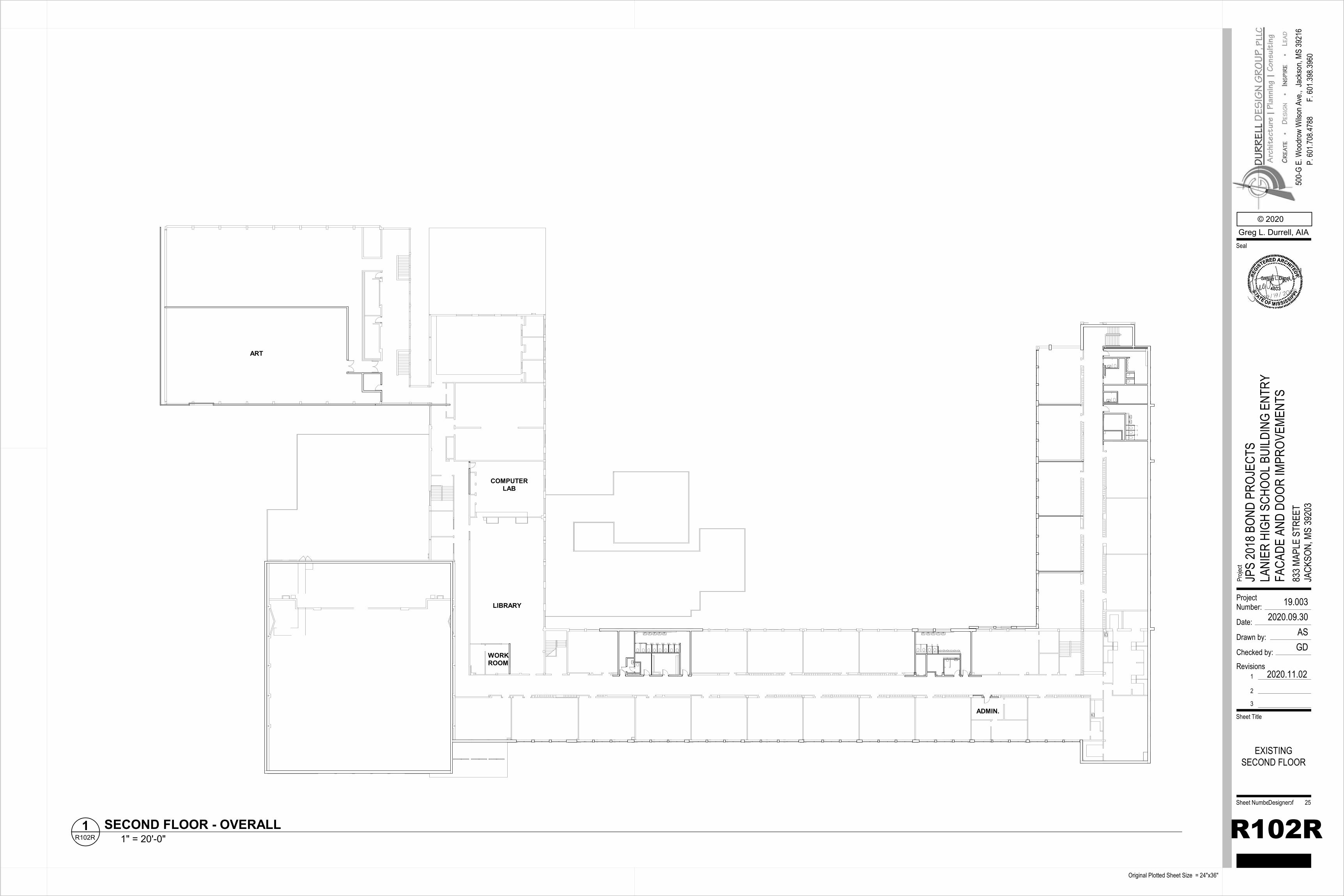
COMPUTERLAB
ART
LIBRARY
WORKROOM
ADMIN.
ProjectNumber:
Date:
Drawn by:
Checked by:
Sheet Number of
Sheet Title
Proje
ct
Original Plotted Sheet Size = 24"x36"
© 2020Greg L. Durrell, AIA
500-
G E.
Woo
drow
Wils
on A
ve.,
Seal
Jack
son,
MS 39
216
P. 60
1.708
.4788
F. 60
1.398
.3960
Revisions1
2
3
2020.11.02
19.0032020.09.30
ASGD
R102R
JPS
2018
BON
D PR
OJEC
TSLA
NIER
HIG
H SC
HOOL
BUI
LDIN
G EN
TRY
FACA
DE A
ND D
OOR
IMPR
OVEM
ENTS
833 M
APLE
STR
EET
JACK
SON,
MS
3920
3
EXISTINGSECOND FLOOR
Designer 25
1" = 20'-0"R102R1 SECOND FLOOR - OVERALL
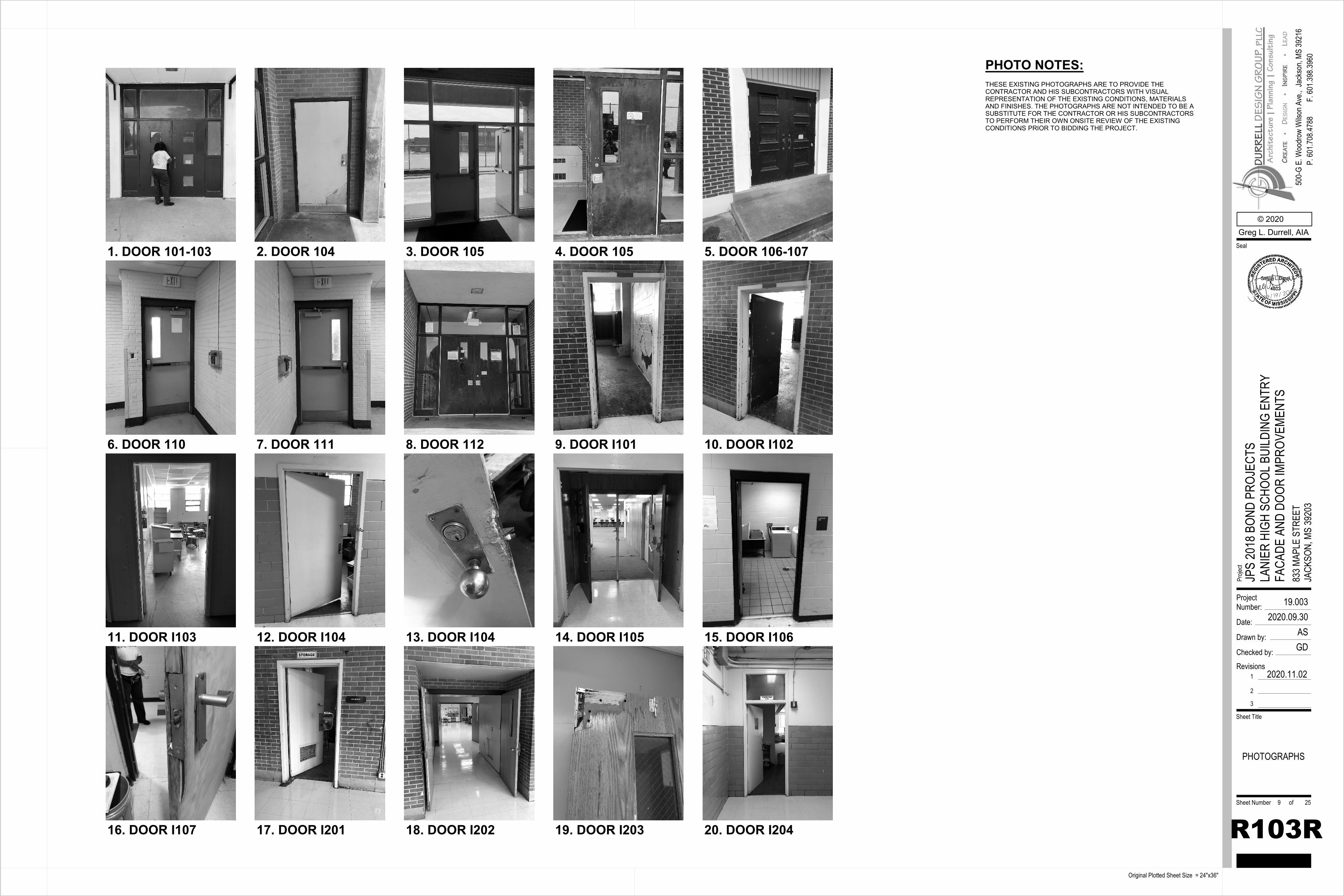
11. DOOR I103 12. DOOR I104 13. DOOR I104 14. DOOR I105
16. DOOR I107 17. DOOR I201 18. DOOR I202 19. DOOR I203 20. DOOR I204
15. DOOR I106
1. DOOR 101-103 2. DOOR 104 3. DOOR 105 4. DOOR 105 5. DOOR 106-107
6. DOOR 110 7. DOOR 111 8. DOOR 112 9. DOOR I101 10. DOOR I102
THESE EXISTING PHOTOGRAPHS ARE TO PROVIDE THE CONTRACTOR AND HIS SUBCONTRACTORS WITH VISUAL REPRESENTATION OF THE EXISTING CONDITIONS, MATERIALS AND FINISHES. THE PHOTOGRAPHS ARE NOT INTENDED TO BE A SUBSTITUTE FOR THE CONTRACTOR OR HIS SUBCONTRACTORS TO PERFORM THEIR OWN ONSITE REVIEW OF THE EXISTING CONDITIONS PRIOR TO BIDDING THE PROJECT.
PHOTO NOTES:
ProjectNumber:
Date:
Drawn by:
Checked by:
Sheet Number of
Sheet Title
Proje
ct
Original Plotted Sheet Size = 24"x36"
© 2020Greg L. Durrell, AIA
500-
G E.
Woo
drow
Wils
on A
ve.,
Seal
Jack
son,
MS 39
216
P. 60
1.708
.4788
F. 60
1.398
.3960
Revisions1
2
3
2020.11.02
19.0032020.09.30
ASGD
R103R
JPS
2018
BON
D PR
OJEC
TSLA
NIER
HIG
H SC
HOOL
BUI
LDIN
G EN
TRY
FACA
DE A
ND D
OOR
IMPR
OVEM
ENTS
833 M
APLE
STR
EET
JACK
SON,
MS
3920
3
PHOTOGRAPHS
9 25
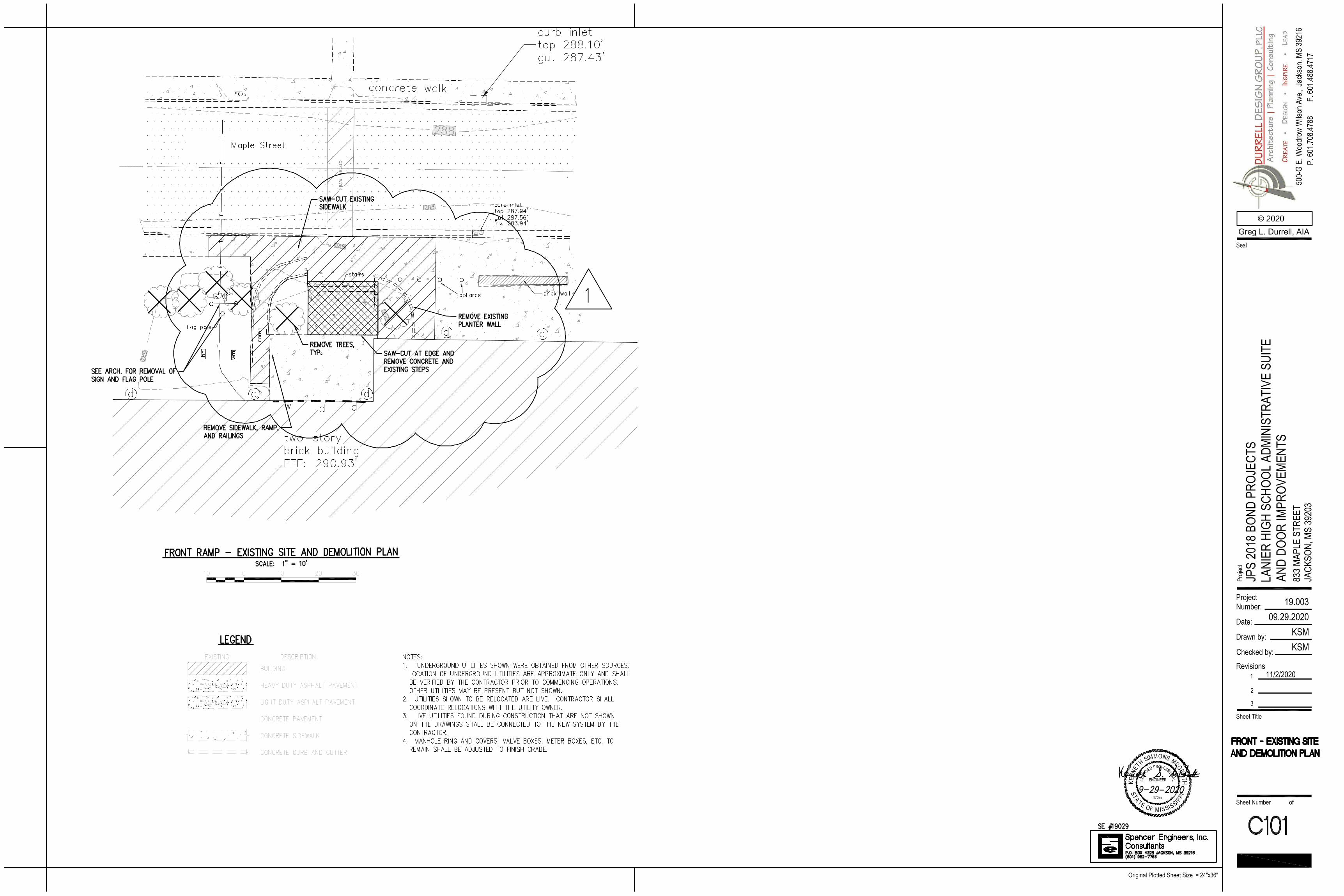
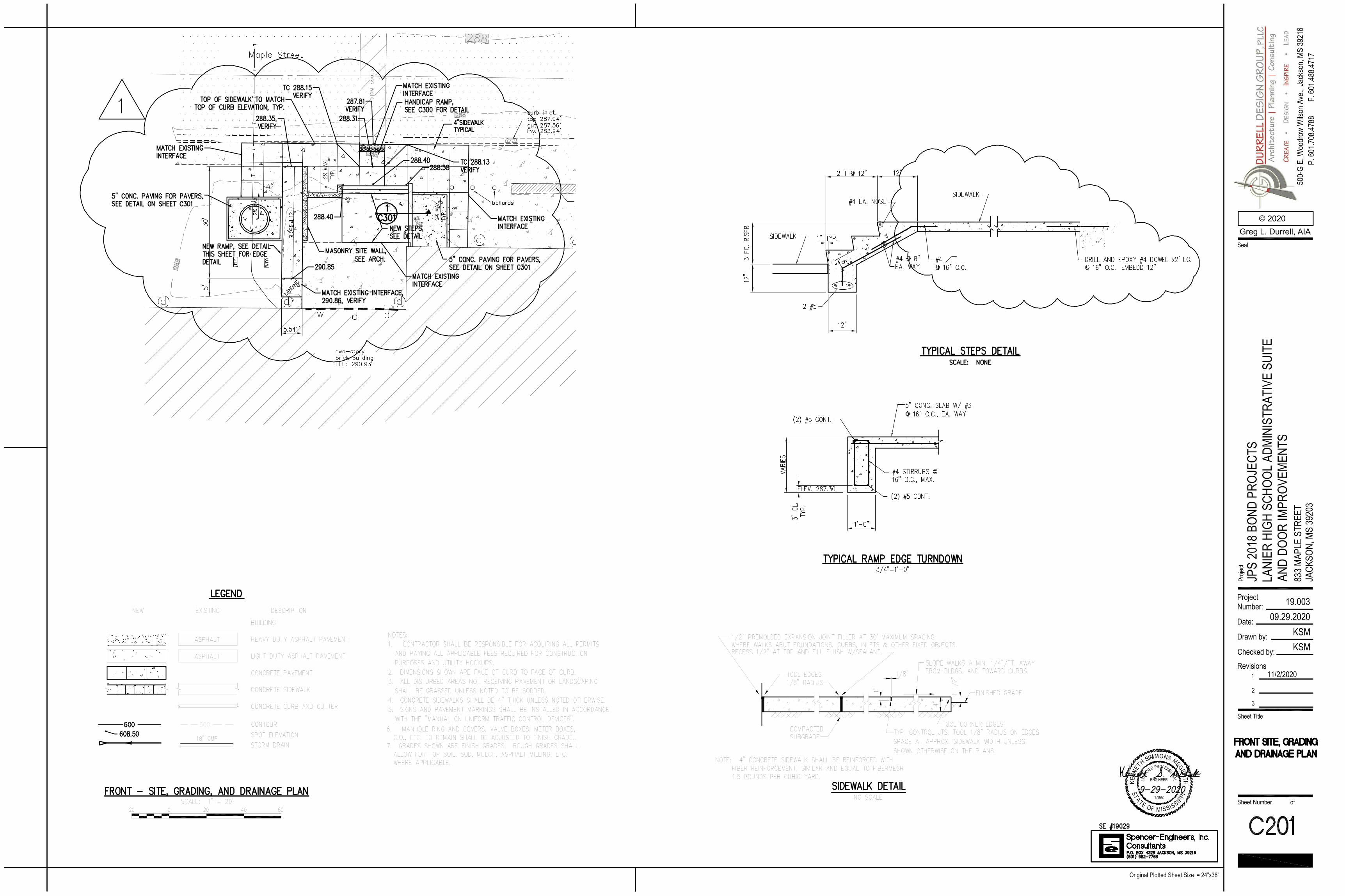
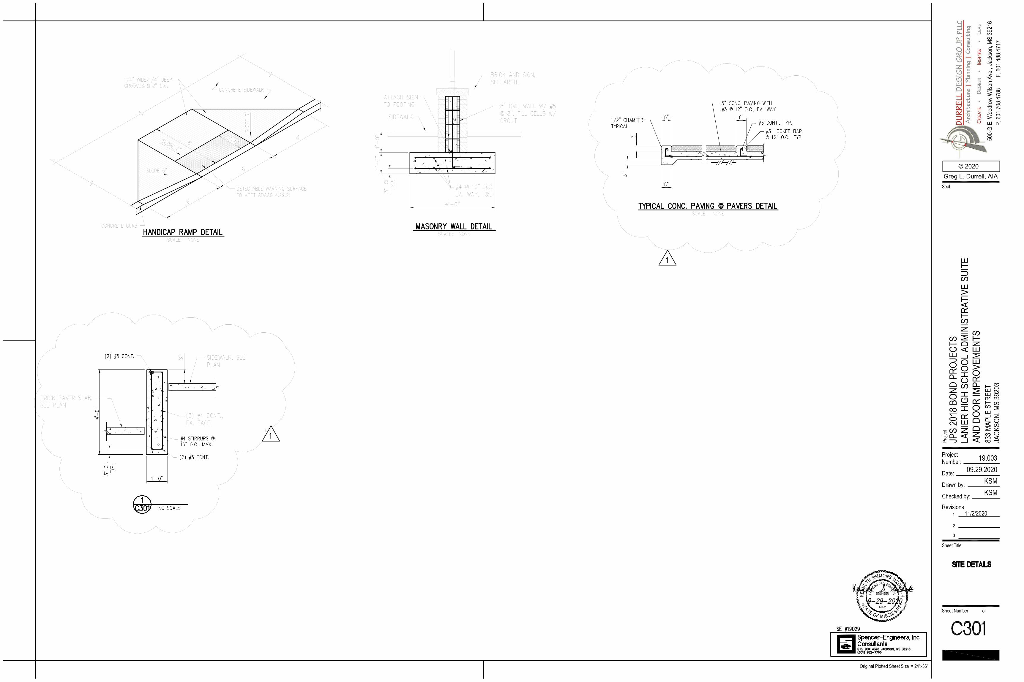
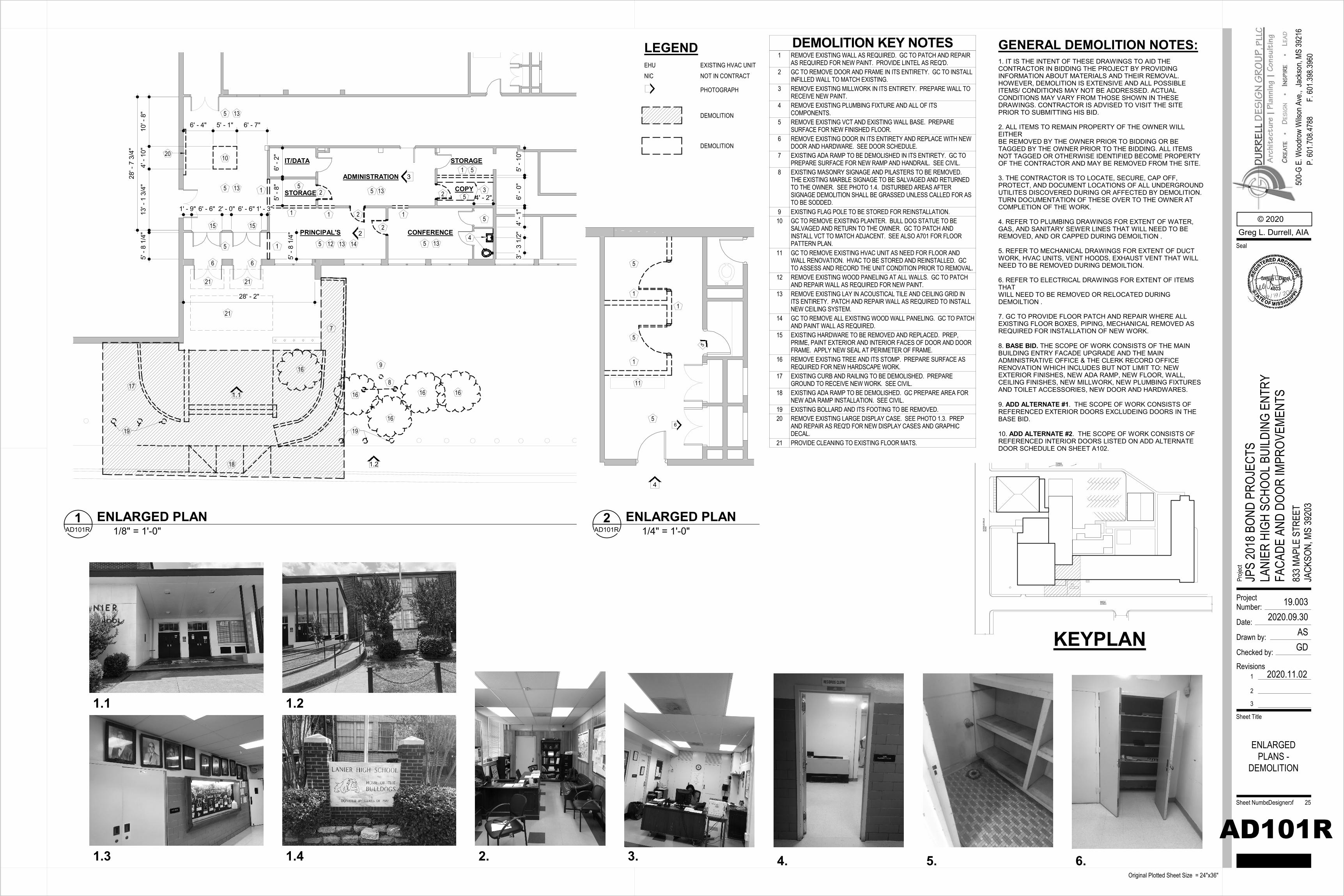
MAPLESTREET
HIT
FIEL
D M
ILLS
RO
AD
TENNISCOURTS
1.1
2
3
IT/DATA
STORAGE COPY
STORAGE
PRINCIPAL'S
ADMINISTRATION
6' -
2"5'
- 8"
5' -
10"
6' -
0"4'
- 1"
3' -
3 1/
2"
4' - 2"1' - 9" 6' - 6" 2' - 0" 6' - 6" 1' - 3"
6' - 4" 5' - 1" 6' - 7"
10' -
8"
4' -
10"
13' -
1 3
/4"
28' - 2"
5' -
8 1/
4"
28' -
7 3
/4"
1
2
1 2
2 3
4
5
5
5
5
5
5
51515
66
1
7
8
9
10
12
13
13 13CONFERENCE
1.2
14
1 1
1616
16
16
16
17
18
5
5
13
13
5
1 2
19
20
5' -
8 1/
4"
21
21 21
19
LEGENDEHU EXISTING HVAC UNITNIC NOT IN CONTRACT
PHOTOGRAPH
DEMOLITION
DEMOLITION
1.3 2. 3. 5. 6.4.1.4
1.1 1.2
1
1
1
5
5
5
11
5
6
4
1. IT IS THE INTENT OF THESE DRAWINGS TO AID THECONTRACTOR IN BIDDING THE PROJECT BY PROVIDINGINFORMATION ABOUT MATERIALS AND THEIR REMOVAL.HOWEVER, DEMOLITION IS EXTENSIVE AND ALL POSSIBLEITEMS/ CONDITIONS MAY NOT BE ADDRESSED. ACTUALCONDITIONS MAY VARY FROM THOSE SHOWN IN THESEDRAWINGS. CONTRACTOR IS ADVISED TO VISIT THE SITEPRIOR TO SUBMITTING HIS BID.
2. ALL ITEMS TO REMAIN PROPERTY OF THE OWNER WILL EITHERBE REMOVED BY THE OWNER PRIOR TO BIDDING OR BETAGGED BY THE OWNER PRIOR TO THE BIDDING. ALL ITEMSNOT TAGGED OR OTHERWISE IDENTIFIED BECOME PROPERTYOF THE CONTRACTOR AND MAY BE REMOVED FROM THE SITE.
3. THE CONTRACTOR IS TO LOCATE, SECURE, CAP OFF,PROTECT, AND DOCUMENT LOCATIONS OF ALL UNDERGROUNDUTILITES DISCOVERED DURING OR AFFECTED BY DEMOLITION.TURN DOCUMENTATION OF THESE OVER TO THE OWNER ATCOMPLETION OF THE WORK.
4. REFER TO PLUMBING DRAWINGS FOR EXTENT OF WATER, GAS, AND SANITARY SEWER LINES THAT WILL NEED TO BE REMOVED, AND OR CAPPED DURING DEMOILTION .
5. REFER TO MECHANICAL DRAWINGS FOR EXTENT OF DUCTWORK, HVAC UNITS, VENT HOODS, EXHAUST VENT THAT WILLNEED TO BE REMOVED DURING DEMOILTION.
6. REFER TO ELECTRICAL DRAWINGS FOR EXTENT OF ITEMS THATWILL NEED TO BE REMOVED OR RELOCATED DURINGDEMOILTION .
7. GC TO PROVIDE FLOOR PATCH AND REPAIR WHERE ALLEXISTING FLOOR BOXES, PIPING, MECHANICAL REMOVED AS REQUIRED FOR INSTALLATION OF NEW WORK.
8. BASE BID. THE SCOPE OF WORK CONSISTS OF THE MAIN BUILDING ENTRY FACADE UPGRADE AND THE MAIN ADMINISTRATIVE OFFICE & THE CLERK RECORD OFFICE RENOVATION WHICH INCLUDES BUT NOT LIMIT TO: NEW EXTERIOR FINISHES, NEW ADA RAMP, NEW FLOOR, WALL, CEILING FINISHES, NEW MILLWORK, NEW PLUMBING FIXTURES AND TOILET ACCESSORIES, NEW DOOR AND HARDWARES.
9. ADD ALTERNATE #1. THE SCOPE OF WORK CONSISTS OF REFERENCED EXTERIOR DOORS EXCLUDEING DOORS IN THE BASE BID.
10. ADD ALTERNATE #2. THE SCOPE OF WORK CONSISTS OF REFERENCED INTERIOR DOORS LISTED ON ADD ALTERNATE DOOR SCHEDULE ON SHEET A102.
GENERAL DEMOLITION NOTES:
KEYPLAN
ProjectNumber:
Date:
Drawn by:
Checked by:
Sheet Number of
Sheet Title
Proje
ct
Original Plotted Sheet Size = 24"x36"
© 2020Greg L. Durrell, AIA
500-
G E.
Woo
drow
Wils
on A
ve.,
Seal
Jack
son,
MS 39
216
P. 60
1.708
.4788
F. 60
1.398
.3960
Revisions1
2
3
2020.11.02
19.0032020.09.30
ASGD
AD101R
JPS
2018
BON
D PR
OJEC
TSLA
NIER
HIG
H SC
HOOL
BUI
LDIN
G EN
TRY
FACA
DE A
ND D
OOR
IMPR
OVEM
ENTS
833 M
APLE
STR
EET
JACK
SON,
MS
3920
3
ENLARGEDPLANS -
DEMOLITION
Designer 25
1/8" = 1'-0"AD101R1 ENLARGED PLAN
DEMOLITION KEY NOTES1 REMOVE EXISTING WALL AS REQUIRED. GC TO PATCH AND REPAIR
AS REQUIRED FOR NEW PAINT. PROVIDE LINTEL AS REQ'D.2 GC TO REMOVE DOOR AND FRAME IN ITS ENTIRETY. GC TO INSTALL
INFILLED WALL TO MATCH EXISTING.3 REMOVE EXISTING MILLWORK IN ITS ENTIRETY. PREPARE WALL TO
RECEIVE NEW PAINT.4 REMOVE EXISTING PLUMBING FIXTURE AND ALL OF ITS
COMPONENTS.5 REMOVE EXISTING VCT AND EXISTING WALL BASE. PREPARE
SURFACE FOR NEW FINISHED FLOOR.6 REMOVE EXISTING DOOR IN ITS ENTIRETY AND REPLACE WITH NEW
DOOR AND HARDWARE. SEE DOOR SCHEDULE.7 EXISTING ADA RAMP TO BE DEMOLISHED IN ITS ENTIRETY. GC TO
PREPARE SURFACE FOR NEW RAMP AND HANDRAIL. SEE CIVIL.8 EXISTING MASONRY SIGNAGE AND PILASTERS TO BE REMOVED.
THE EXISTING MARBLE SIGNAGE TO BE SALVAGED AND RETURNEDTO THE OWNER. SEE PHOTO 1.4. DISTURBED AREAS AFTERSIGNAGE DEMOLITION SHALL BE GRASSED UNLESS CALLED FOR ASTO BE SODDED.
9 EXISTING FLAG POLE TO BE STORED FOR REINSTALLATION.10 GC TO REMOVE EXISTING PLANTER. BULL DOG STATUE TO BE
SALVAGED AND RETURN TO THE OWNER. GC TO PATCH ANDINSTALL VCT TO MATCH ADJACENT. SEE ALSO A701 FOR FLOORPATTERN PLAN.
11 GC TO REMOVE EXISTING HVAC UNIT AS NEED FOR FLOOR ANDWALL RENOVATION. HVAC TO BE STORED AND REINSTALLED. GCTO ASSESS AND RECORD THE UNIT CONDITION PRIOR TO REMOVAL.
12 REMOVE EXISTING WOOD PANELING AT ALL WALLS. GC TO PATCHAND REPAIR WALL AS REQUIRED FOR NEW PAINT.
13 REMOVE EXISTING LAY IN ACOUSTICAL TILE AND CEILING GRID INITS ENTIRETY. PATCH AND REPAIR WALL AS REQUIRED TO INSTALLNEW CEILING SYSTEM.
14 GC TO REMOVE ALL EXISTING WOOD WALL PANELING. GC TO PATCHAND PAINT WALL AS REQUIRED.
15 EXISTING HARDWARE TO BE REMOVED AND REPLACED. PREP,PRIME, PAINT EXTERIOR AND INTERIOR FACES OF DOOR AND DOORFRAME. APPLY NEW SEAL AT PERIMETER OF FRAME.
16 REMOVE EXISTING TREE AND ITS STOMP. PREPARE SURFACE ASREQUIRED FOR NEW HARDSCAPE WORK.
17 EXISTING CURB AND RAILING TO BE DEMOLISHED. PREPAREGROUND TO RECEIVE NEW WORK. SEE CIVIL.
18 EXISTING ADA RAMP TO BE DEMOLISHED. GC PREPARE AREA FORNEW ADA RAMP INSTALLATION. SEE CIVIL.
19 EXISTING BOLLARD AND ITS FOOTING TO BE REMOVED.20 REMOVE EXISTING LARGE DISPLAY CASE. SEE PHOTO 1.3. PREP
AND REPAIR AS REQ'D FOR NEW DISPLAY CASES AND GRAPHICDECAL.
21 PROVIDE CLEANING TO EXISTING FLOOR MATS.
1/4" = 1'-0"AD101R2 ENLARGED PLAN
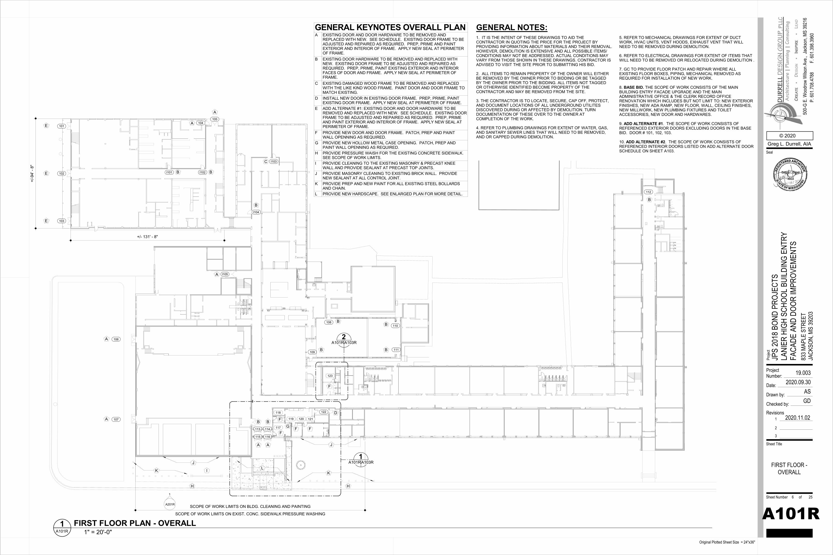
+/-9
4' -
8"
+/- 131' - 8"
I103
I102I101
104105
103
I104
I105
A
A
C
BB
B
E
A
102
101
E
E
106
107
108110
109111
112
113 114
115 116
A
A
A A
B B
F
BB
BB
B
117
F
118 122 D
123
F
119 120 121
G F F
1A101RA103R
2A101RA103R
A201R
1
SCOPE OF WORK LIMITS ON EXIST. CONC. SIDEWALK PRESSURE WASHING
SCOPE OF WORK LIMITS ON BLDG. CLEANING AND PAINTING
H H
I
J
J
K KL
1. IT IS THE INTENT OF THESE DRAWINGS TO AID THE CONTRACTOR IN QUOTING THE PRICE FOR THE PROJECT BY PROVIDING INFORMATION ABOUT MATERIALS AND THEIR REMOVAL. HOWEVER, DEMOLITION IS EXTENSIVE AND ALL POSSIBLE ITEMS/ CONDITIONS MAY NOT BE ADDRESSED. ACTUAL CONDITIONS MAY VARY FROM THOSE SHOWN IN THESE DRAWINGS. CONTRACTOR IS ADVISED TO VISIT THE SITE PRIOR TO SUBMITTING HIS BID.
2. ALL ITEMS TO REMAIN PROPERTY OF THE OWNER WILL EITHER BE REMOVED BY THE OWNER PRIOR TO BIDDING OR BE TAGGED BY THE OWNER PRIOR TO THE BIDDING. ALL ITEMS NOT TAGGED OR OTHERWISE IDENTIFIED BECOME PROPERTY OF THE CONTRACTOR AND MAY BE REMOVED FROM THE SITE.
3. THE CONTRACTOR IS TO LOCATE, SECURE, CAP OFF, PROTECT, AND DOCUMENT LOCATIONS OF ALL UNDERGROUND UTILITES DISCOVERED DURING OR AFFECTED BY DEMOLITION. TURN DOCUMENTATION OF THESE OVER TO THE OWNER AT COMPLETION OF THE WORK.
4. REFER TO PLUMBING DRAWINGS FOR EXTENT OF WATER, GAS, AND SANITARY SEWER LINES THAT WILL NEED TO BE REMOVED, AND OR CAPPED DURING DEMOLITION.
GENERAL NOTES:5. REFER TO MECHANICAL DRAWINGS FOR EXTENT OF DUCT WORK, HVAC UNITS, VENT HOODS, EXHAUST VENT THAT WILL NEED TO BE REMOVED DURING DEMOLITION.
6. REFER TO ELECTRICAL DRAWINGS FOR EXTENT OF ITEMS THATWILL NEED TO BE REMOVED OR RELOCATED DURING DEMOLITION .
7. GC TO PROVIDE FLOOR PATCH AND REPAIR WHERE ALL EXISTING FLOOR BOXES, PIPING, MECHANICAL REMOVED AS REQUIRED FOR INSTALLATION OF NEW WORK.
8. BASE BID. THE SCOPE OF WORK CONSISTS OF THE MAIN BUILDING ENTRY FACADE UPGRADE AND THE MAIN ADMINISTRATIVE OFFICE & THE CLERK RECORD OFFICE RENOVATION WHICH INCLUDES BUT NOT LIMIT TO: NEW EXTERIOR FINISHES, NEW ADA RAMP, NEW FLOOR, WALL, CEILING FINISHES, NEW MILLWORK, NEW PLUMBING FIXTURES AND TOILET ACCESSORIES, NEW DOOR AND HARDWARES.
9. ADD ALTERNATE #1. THE SCOPE OF WORK CONSISTS OF REFERENCED EXTERIOR DOORS EXCLUDING DOORS IN THE BASE BID. DOOR # 101, 102, 103.
10. ADD ALTERNATE #2. THE SCOPE OF WORK CONSISTS OF REFERENCED INTERIOR DOORS LISTED ON ADD ALTERNATE DOOR SCHEDULE ON SHEET A103.
ProjectNumber:
Date:
Drawn by:
Checked by:
Sheet Number of
Sheet Title
Proje
ct
Original Plotted Sheet Size = 24"x36"
© 2020Greg L. Durrell, AIA
500-
G E.
Woo
drow
Wils
on A
ve.,
Seal
Jack
son,
MS 39
216
P. 60
1.708
.4788
F. 60
1.398
.3960
Revisions1
2
3
2020.11.02
19.0032020.09.30
ASGD
A101R
JPS
2018
BON
D PR
OJEC
TSLA
NIER
HIG
H SC
HOOL
BUI
LDIN
G EN
TRY
FACA
DE A
ND D
OOR
IMPR
OVEM
ENTS
833 M
APLE
STR
EET
JACK
SON,
MS
3920
3
FIRST FLOOR -OVERALL
6 25
1" = 20'-0"A101R1 FIRST FLOOR PLAN - OVERALL
GENERAL KEYNOTES OVERALL PLANA EXISTING DOOR AND DOOR HARDWARE TO BE REMOVED AND
REPLACED WITH NEW. SEE SCHEDULE. EXISTING DOOR FRAME TO BEADJUSTED AND REPAIRED AS REQUIRED. PREP, PRIME AND PAINTEXTERIOR AND INTERIOR OF FRAME. APPLY NEW SEAL AT PERIMETEROF FRAME.
B EXISTING DOOR HARDWARE TO BE REMOVED AND REPLACED WITHNEW. EXISTING DOOR FRAME TO BE ADJUSTED AND REPAIRED ASREQUIRED. PREP, PRIME, PAINT EXISTING EXTERIOR AND INTERIORFACES OF DOOR AND FRAME. APPLY NEW SEAL AT PERIMETER OFFRAME.
C EXISTING DAMAGED WOOD FRAME TO BE REMOVED AND REPLACEDWITH THE LIKE KIND WOOD FRAME. PAINT DOOR AND DOOR FRAME TOMATCH EXISTING.
D INSTALL NEW DOOR IN EXISTING DOOR FRAME. PREP, PRIME, PAINTEXISTING DOOR FRAME. APPLY NEW SEAL AT PERIMETER OF FRAME.
E ADD ALTERNATE #1: EXISTING DOOR AND DOOR HARDWARE TO BEREMOVED AND REPLACED WITH NEW. SEE SCHEDULE. EXISTING DOORFRAME TO BE ADJUSTED AND REPAIRED AS REQUIRED. PREP, PRIMEAND PAINT EXTERIOR AND INTERIOR OF FRAME. APPLY NEW SEAL ATPERIMETER OF FRAME.
F PROVIDE NEW DOOR AND DOOR FRAME. PATCH, PREP AND PAINTWALL OPENNING AS REQUIRED.
G PROVIDE NEW HOLLOW METAL CASE OPENING. PATCH, PREP ANDPAINT WALL OPENNING AS REQUIRED.
H PROVIDE PRESSURE WAISH FOR THE EXISTING CONCRETE SIDEWALK.SEE SCOPE OF WORK LIMITS.
I PROVIDE CLEANING TO THE EXISTING MASONRY & PRECAST KNEEWALL AND PROVIDE SEALANT AT PRECAST TOP JOINTS.
J PROVIDE MASONRY CLEANING TO EXISTING BRICK WALL. PROVIDENEW SEALANT AT ALL CONTROL JOINT.
K PROVIDE PREP AND NEW PAINT FOR ALL EXISTING STEEL BOLLARDSAND CHAIN.
L PROVIDE NEW HARDSCAPE. SEE ENLARGED PLAN FOR MORE DETAIL.
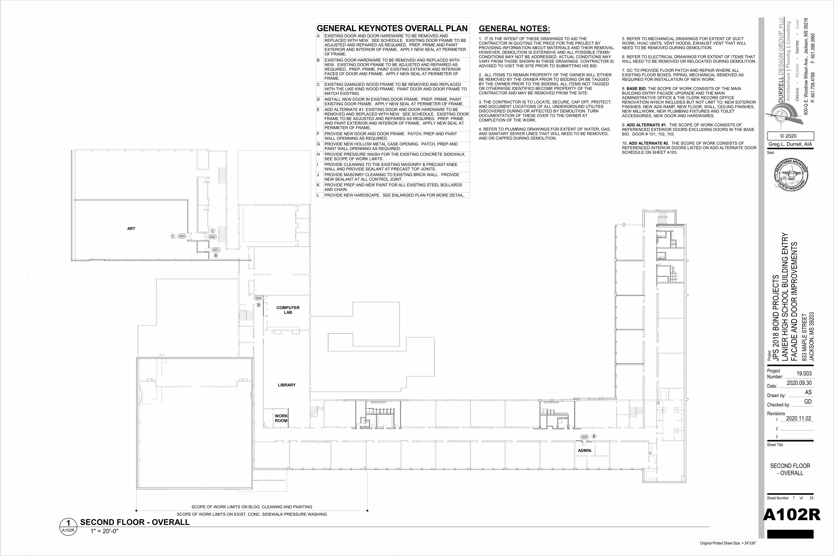
I201
I202I203
COMPUTERLAB
ART
I204
LIBRARY
WORKROOM
I205
ADMIN.
CC
B
B
B
SCOPE OF WORK LIMITS ON EXIST. CONC. SIDEWALK PRESSURE WASHING
SCOPE OF WORK LIMITS ON BLDG. CLEANING AND PAINTING
1. IT IS THE INTENT OF THESE DRAWINGS TO AID THE CONTRACTOR IN QUOTING THE PRICE FOR THE PROJECT BY PROVIDING INFORMATION ABOUT MATERIALS AND THEIR REMOVAL. HOWEVER, DEMOLITION IS EXTENSIVE AND ALL POSSIBLE ITEMS/ CONDITIONS MAY NOT BE ADDRESSED. ACTUAL CONDITIONS MAY VARY FROM THOSE SHOWN IN THESE DRAWINGS. CONTRACTOR IS ADVISED TO VISIT THE SITE PRIOR TO SUBMITTING HIS BID.
2. ALL ITEMS TO REMAIN PROPERTY OF THE OWNER WILL EITHER BE REMOVED BY THE OWNER PRIOR TO BIDDING OR BE TAGGED BY THE OWNER PRIOR TO THE BIDDING. ALL ITEMS NOT TAGGED OR OTHERWISE IDENTIFIED BECOME PROPERTY OF THE CONTRACTOR AND MAY BE REMOVED FROM THE SITE.
3. THE CONTRACTOR IS TO LOCATE, SECURE, CAP OFF, PROTECT, AND DOCUMENT LOCATIONS OF ALL UNDERGROUND UTILITES DISCOVERED DURING OR AFFECTED BY DEMOLITION. TURN DOCUMENTATION OF THESE OVER TO THE OWNER AT COMPLETION OF THE WORK.
4. REFER TO PLUMBING DRAWINGS FOR EXTENT OF WATER, GAS, AND SANITARY SEWER LINES THAT WILL NEED TO BE REMOVED, AND OR CAPPED DURING DEMOLITION.
GENERAL NOTES:5. REFER TO MECHANICAL DRAWINGS FOR EXTENT OF DUCT WORK, HVAC UNITS, VENT HOODS, EXHAUST VENT THAT WILL NEED TO BE REMOVED DURING DEMOLITION.
6. REFER TO ELECTRICAL DRAWINGS FOR EXTENT OF ITEMS THATWILL NEED TO BE REMOVED OR RELOCATED DURING DEMOLITION .
7. GC TO PROVIDE FLOOR PATCH AND REPAIR WHERE ALL EXISTING FLOOR BOXES, PIPING, MECHANICAL REMOVED AS REQUIRED FOR INSTALLATION OF NEW WORK.
8. BASE BID. THE SCOPE OF WORK CONSISTS OF THE MAIN BUILDING ENTRY FACADE UPGRADE AND THE MAIN ADMINISTRATIVE OFFICE & THE CLERK RECORD OFFICE RENOVATION WHICH INCLUDES BUT NOT LIMIT TO: NEW EXTERIOR FINISHES, NEW ADA RAMP, NEW FLOOR, WALL, CEILING FINISHES, NEW MILLWORK, NEW PLUMBING FIXTURES AND TOILET ACCESSORIES, NEW DOOR AND HARDWARES.
9. ADD ALTERNATE #1. THE SCOPE OF WORK CONSISTS OF REFERENCED EXTERIOR DOORS EXCLUDING DOORS IN THE BASE BID. DOOR # 101, 102, 103.
10. ADD ALTERNATE #2. THE SCOPE OF WORK CONSISTS OF REFERENCED INTERIOR DOORS LISTED ON ADD ALTERNATE DOOR SCHEDULE ON SHEET A103.
ProjectNumber:
Date:
Drawn by:
Checked by:
Sheet Number of
Sheet Title
Proje
ct
Original Plotted Sheet Size = 24"x36"
© 2020Greg L. Durrell, AIA
500-
G E.
Woo
drow
Wils
on A
ve.,
Seal
Jack
son,
MS 39
216
P. 60
1.708
.4788
F. 60
1.398
.3960
Revisions1
2
3
2020.11.02
19.0032020.09.30
ASGD
A102R
JPS
2018
BON
D PR
OJEC
TSLA
NIER
HIG
H SC
HOOL
BUI
LDIN
G EN
TRY
FACA
DE A
ND D
OOR
IMPR
OVEM
ENTS
833 M
APLE
STR
EET
JACK
SON,
MS
3920
3
SECOND FLOOR- OVERALL
7 25
1" = 20'-0"A102R1 SECOND FLOOR - OVERALL
GENERAL KEYNOTES OVERALL PLANA EXISTING DOOR AND DOOR HARDWARE TO BE REMOVED AND
REPLACED WITH NEW. SEE SCHEDULE. EXISTING DOOR FRAME TO BEADJUSTED AND REPAIRED AS REQUIRED. PREP, PRIME AND PAINTEXTERIOR AND INTERIOR OF FRAME. APPLY NEW SEAL AT PERIMETEROF FRAME.
B EXISTING DOOR HARDWARE TO BE REMOVED AND REPLACED WITHNEW. EXISTING DOOR FRAME TO BE ADJUSTED AND REPAIRED ASREQUIRED. PREP, PRIME, PAINT EXISTING EXTERIOR AND INTERIORFACES OF DOOR AND FRAME. APPLY NEW SEAL AT PERIMETER OFFRAME.
C EXISTING DAMAGED WOOD FRAME TO BE REMOVED AND REPLACEDWITH THE LIKE KIND WOOD FRAME. PAINT DOOR AND DOOR FRAME TOMATCH EXISTING.
D INSTALL NEW DOOR IN EXISTING DOOR FRAME. PREP, PRIME, PAINTEXISTING DOOR FRAME. APPLY NEW SEAL AT PERIMETER OF FRAME.
E ADD ALTERNATE #1: EXISTING DOOR AND DOOR HARDWARE TO BEREMOVED AND REPLACED WITH NEW. SEE SCHEDULE. EXISTING DOORFRAME TO BE ADJUSTED AND REPAIRED AS REQUIRED. PREP, PRIMEAND PAINT EXTERIOR AND INTERIOR OF FRAME. APPLY NEW SEAL ATPERIMETER OF FRAME.
F PROVIDE NEW DOOR AND DOOR FRAME. PATCH, PREP AND PAINTWALL OPENNING AS REQUIRED.
G PROVIDE NEW HOLLOW METAL CASE OPENING. PATCH, PREP ANDPAINT WALL OPENNING AS REQUIRED.
H PROVIDE PRESSURE WAISH FOR THE EXISTING CONCRETE SIDEWALK.SEE SCOPE OF WORK LIMITS.
I PROVIDE CLEANING TO THE EXISTING MASONRY & PRECAST KNEEWALL AND PROVIDE SEALANT AT PRECAST TOP JOINTS.
J PROVIDE MASONRY CLEANING TO EXISTING BRICK WALL. PROVIDENEW SEALANT AT ALL CONTROL JOINT.
K PROVIDE PREP AND NEW PAINT FOR ALL EXISTING STEEL BOLLARDSAND CHAIN.
L PROVIDE NEW HARDSCAPE. SEE ENLARGED PLAN FOR MORE DETAIL.
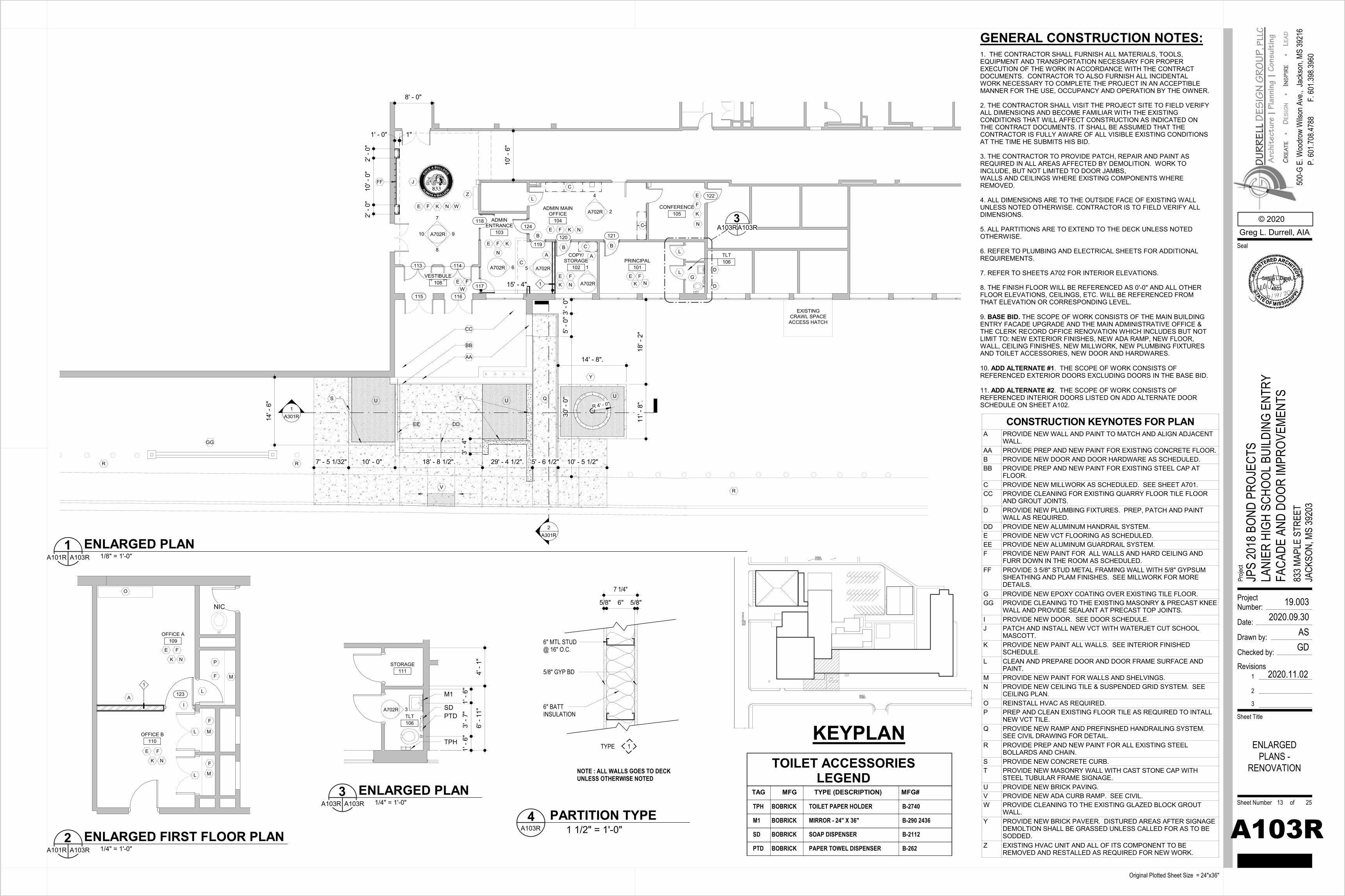
MAPLESTREET
HIT
FIEL
D M
ILLS
RO
AD
TENNISCOURTS
OFFICE A109
OFFICE B110
AI
123
E F
E F
NIC
L
L
L
M
M
O
K
K
N
N
M
F
F
F
P
1
ADMINENTRANCE
103
ADMIN MAINOFFICE
104
COPY/STORAGE
102PRINCIPAL
101
CONFERENCE105
VESTIBULE108
A A
B
B B
C
C
D
D
E
E
E E
E
CF
F
FF
F
G
120 121
119
115 116
114113
15' - 4"
30' -
0"
5' -
0"3'
- 0"
J
3A103RA103R
K
K
K K
TLT106
K
N
N N
NN
A702R
4
2
A702R
1
8' - 0"
Q
122
EXISTING CRAWL SPACEACCESS HATCH
7' - 5 1/32" 10' - 0" 18' - 8 1/2". 29' - 4 1/2". 5' - 6 1/2" 10' - 5 1/2"
14' -
6"
R
R
3' -
4"
S TU U
V
1
CA702R 6 A702R5
A702R
8
910
7
E F
E F K N
117
W
W
118
Z
124
L
L
L
R
AA
BB
CC
DDEE
2' -
0"10
' - 0
"2'
- 0"
1' - 0" 1"
FF
GG
10' -
6"
1A301R
R 4' - 0"
2A301R
Y
11' -
8".
18' -
2"
14' - 8".
U
1. THE CONTRACTOR SHALL FURNISH ALL MATERIALS, TOOLS, EQUIPMENT AND TRANSPORTATION NECESSARY FOR PROPER EXECUTION OF THE WORK IN ACCORDANCE WITH THE CONTRACT DOCUMENTS. CONTRACTOR TO ALSO FURNISH ALL INCIDENTAL WORK NECESSARY TO COMPLETE THE PROJECT IN AN ACCEPTIBLEMANNER FOR THE USE, OCCUPANCY AND OPERATION BY THE OWNER.
2. THE CONTRACTOR SHALL VISIT THE PROJECT SITE TO FIELD VERIFY ALL DIMENSIONS AND BECOME FAMILIAR WITH THE EXISTING CONDITIONS THAT WILL AFFECT CONSTRUCTION AS INDICATED ON THE CONTRACT DOCUMENTS. IT SHALL BE ASSUMED THAT THE CONTRACTOR IS FULLY AWARE OF ALL VISIBLE EXISTING CONDITIONS AT THE TIME HE SUBMITS HIS BID.
3. THE CONTRACTOR TO PROVIDE PATCH, REPAIR AND PAINT AS REQUIRED IN ALL AREAS AFFECTED BY DEMOLITION. WORK TO INCLUDE, BUT NOT LIMITED TO DOOR JAMBS,WALLS AND CEILINGS WHERE EXISTING COMPONENTS WHERE REMOVED.
4. ALL DIMENSIONS ARE TO THE OUTSIDE FACE OF EXISTING WALL UNLESS NOTED OTHERWISE. CONTRACTOR IS TO FIELD VERIFY ALL DIMENSIONS.
5. ALL PARTITIONS ARE TO EXTEND TO THE DECK UNLESS NOTEDOTHERWISE.
6. REFER TO PLUMBING AND ELECTRICAL SHEETS FOR ADDITIONALREQUIREMENTS.
7. REFER TO SHEETS A702 FOR INTERIOR ELEVATIONS.
8. THE FINISH FLOOR WILL BE REFERENCED AS 0'-0" AND ALL OTHER FLOOR ELEVATIONS, CEILINGS, ETC. WILL BE REFERENCED FROM THAT ELEVATION OR CORRESPONDING LEVEL.
9. BASE BID. THE SCOPE OF WORK CONSISTS OF THE MAIN BUILDING ENTRY FACADE UPGRADE AND THE MAIN ADMINISTRATIVE OFFICE & THE CLERK RECORD OFFICE RENOVATION WHICH INCLUDES BUT NOT LIMIT TO: NEW EXTERIOR FINISHES, NEW ADA RAMP, NEW FLOOR, WALL, CEILING FINISHES, NEW MILLWORK, NEW PLUMBING FIXTURES AND TOILET ACCESSORIES, NEW DOOR AND HARDWARES.
10. ADD ALTERNATE #1. THE SCOPE OF WORK CONSISTS OF REFERENCED EXTERIOR DOORS EXCLUDING DOORS IN THE BASE BID.
11. ADD ALTERNATE #2. THE SCOPE OF WORK CONSISTS OF REFERENCED INTERIOR DOORS LISTED ON ADD ALTERNATE DOOR SCHEDULE ON SHEET A102.
GENERAL CONSTRUCTION NOTES:
4' -
1"6'
- 11
"
1' -
6"3'
- 7"
1' -
6"
A702R 3TLT106
SDPTD
TPH
M1
STORAGE111
TOILET ACCESSORIES LEGEND
TPH BOBRICK TOILET PAPER HOLDER B-2740
TAG MFG TYPE (DESCRIPTION) MFG#
M1 BOBRICK MIRROR - 24" X 36" B-290 2436
SD BOBRICK SOAP DISPENSER B-2112
PTD BOBRICK PAPER TOWEL DISPENSER B-262
NOTE : ALL WALLS GOES TO DECK UNLESS OTHERWISE NOTED
5/8" GYP BD
5/8" 6" 5/8"
TYPE 1
6" MTL STUD@ 16" O.C.
6" BATT INSULATION
7 1/4"
KEYPLAN
ProjectNumber:
Date:
Drawn by:
Checked by:
Sheet Number of
Sheet Title
Proje
ct
Original Plotted Sheet Size = 24"x36"
© 2020Greg L. Durrell, AIA
500-
G E.
Woo
drow
Wils
on A
ve.,
Seal
Jack
son,
MS 39
216
P. 60
1.708
.4788
F. 60
1.398
.3960
Revisions1
2
3
2020.11.02
19.0032020.09.30
ASGD
A103R
JPS
2018
BON
D PR
OJEC
TSLA
NIER
HIG
H SC
HOOL
BUI
LDIN
G EN
TRY
FACA
DE A
ND D
OOR
IMPR
OVEM
ENTS
833 M
APLE
STR
EET
JACK
SON,
MS
3920
3
ENLARGEDPLANS -
RENOVATION
13 25
1/4" = 1'-0"A101R A103R2 ENLARGED FIRST FLOOR PLAN
1/8" = 1'-0"A101R A103R1 ENLARGED PLAN
CONSTRUCTION KEYNOTES FOR PLANA PROVIDE NEW WALL AND PAINT TO MATCH AND ALIGN ADJACENT
WALL.AA PROVIDE PREP AND NEW PAINT FOR EXISTING CONCRETE FLOOR.B PROVIDE NEW DOOR AND DOOR HARDWARE AS SCHEDULED.BB PROVIDE PREP AND NEW PAINT FOR EXISTING STEEL CAP AT
FLOOR.C PROVIDE NEW MILLWORK AS SCHEDULED. SEE SHEET A701.CC PROVIDE CLEANING FOR EXISTING QUARRY FLOOR TILE FLOOR
AND GROUT JOINTS.D PROVIDE NEW PLUMBING FIXTURES. PREP, PATCH AND PAINT
WALL AS REQUIRED.DD PROVIDE NEW ALUMINUM HANDRAIL SYSTEM.E PROVIDE NEW VCT FLOORING AS SCHEDULED.EE PROVIDE NEW ALUMINUM GUARDRAIL SYSTEM.F PROVIDE NEW PAINT FOR ALL WALLS AND HARD CEILING AND
FURR DOWN IN THE ROOM AS SCHEDULED.FF PROVIDE 3 5/8" STUD METAL FRAMING WALL WITH 5/8" GYPSUM
SHEATHING AND PLAM FINISHES. SEE MILLWORK FOR MOREDETAILS.
G PROVIDE NEW EPOXY COATING OVER EXISTING TILE FLOOR.GG PROVIDE CLEANING TO THE EXISTING MASONRY & PRECAST KNEE
WALL AND PROVIDE SEALANT AT PRECAST TOP JOINTS.I PROVIDE NEW DOOR. SEE DOOR SCHEDULE.J PATCH AND INSTALL NEW VCT WITH WATERJET CUT SCHOOL
MASCOTT.K PROVIDE NEW PAINT ALL WALLS. SEE INTERIOR FINISHED
SCHEDULE.L CLEAN AND PREPARE DOOR AND DOOR FRAME SURFACE AND
PAINT.M PROVIDE NEW PAINT FOR WALLS AND SHELVINGS.N PROVIDE NEW CEILING TILE & SUSPENDED GRID SYSTEM. SEE
CEILING PLAN.O REINSTALL HVAC AS REQUIRED.P PREP AND CLEAN EXISTING FLOOR TILE AS REQUIRED TO INTALL
NEW VCT TILE.Q PROVIDE NEW RAMP AND PREFINSHED HANDRAILING SYSTEM.
SEE CIVIL DRAWING FOR DETAIL.R PROVIDE PREP AND NEW PAINT FOR ALL EXISTING STEEL
BOLLARDS AND CHAIN.S PROVIDE NEW CONCRETE CURB.T PROVIDE NEW MASONRY WALL WITH CAST STONE CAP WITH
STEEL TUBULAR FRAME SIGNAGE.U PROVIDE NEW BRICK PAVING.V PROVIDE NEW ADA CURB RAMP. SEE CIVIL.W PROVIDE CLEANING TO THE EXISTING GLAZED BLOCK GROUT
WALL.Y PROVIDE NEW BRICK PAVEER. DISTURED AREAS AFTER SIGNAGE
DEMOLTION SHALL BE GRASSED UNLESS CALLED FOR AS TO BESODDED.
Z EXISTING HVAC UNIT AND ALL OF ITS COMPONENT TO BEREMOVED AND RESTALLED AS REQUIRED FOR NEW WORK.
1/4" = 1'-0"A103R A103R3 ENLARGED PLAN
1 1/2" = 1'-0"A103R4 PARTITION TYPE
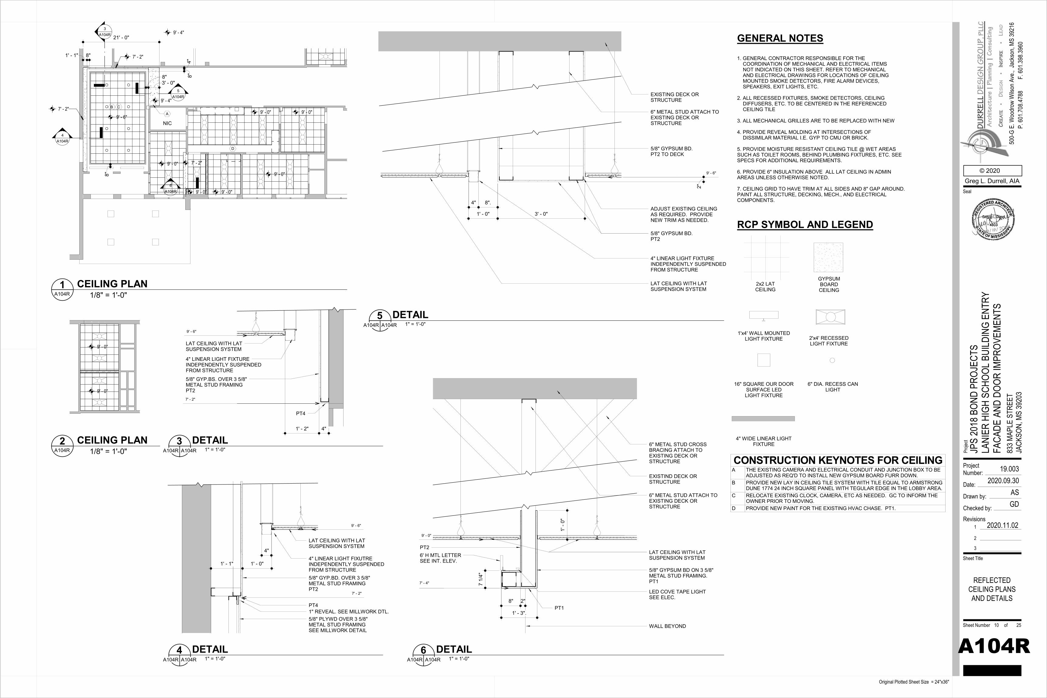
9' - 6"
9' - 4"
9' - 0"
9' - 0"
9' - 0" 9' - 0"
21' - 0"
5A104R
NIC
9' - 0"
9' - 0"6
A104R
7' - 2"
7' - 2"
8"3' - 0"
9' - 4"
7' - 2"
1' - 1" 8"
8"
8"4"
A
3A104R
4A104R
CB
D
9' - 0"
9' - 0"
1. GENERAL CONTRACTOR RESPONSIBLE FOR THE COORDINATION OF MECHANICAL AND ELECTRICAL ITEMS NOT INDICATED ON THIS SHEET. REFER TO MECHANICAL AND ELECTRICAL DRAWINGS FOR LOCATIONS OF CEILING MOUNTED SMOKE DETECTORS, FIRE ALARM DEVICES, SPEAKERS, EXIT LIGHTS, ETC.
2. ALL RECESSED FIXTURES, SMOKE DETECTORS, CEILING DIFFUSERS, ETC. TO BE CENTERED IN THE REFERENCED CEILING TILE
3. ALL MECHANICAL GRILLES ARE TO BE REPLACED WITH NEW
4. PROVIDE REVEAL MOLDING AT INTERSECTIONS OF DISSIMILAR MATERIAL I.E. GYP TO CMU OR BRICK.
5. PROVIDE MOISTURE RESISTANT CEILING TILE @ WET AREAS SUCH AS TOILET ROOMS, BEHIND PLUMBING FIXTURES, ETC. SEE SPECS FOR ADDITIONAL REQUIREMENTS.
6. PROVIDE 6" INSULATION ABOVE ALL LAT CEILING IN ADMIN AREAS UNLESS OTHERWISE NOTED.
7. CEILING GRID TO HAVE TRIM AT ALL SIDES AND 8" GAP AROUND. PAINT ALL STRUCTURE, DECKING, MECH., AND ELECTRICAL COMPONENTS.
GENERAL NOTES
2'x4' RECESSEDLIGHT FIXTURE
RCP SYMBOL AND LEGEND
GYPSUM BOARD CEILING
2x2 LAT CEILING
1'x4' WALL MOUNTEDLIGHT FIXTURE
16" SQUARE OUR DOORSURFACE LEDLIGHT FIXTURE
6" DIA. RECESS CAN LIGHT
4" WIDE LINEAR LIGHTFIXTURE
EXISTING DECK OR STRUCTURE
6" METAL STUD ATTACH TO EXISTING DECK OR STRUCTURE
LAT CEILING WITH LAT SUSPENSION SYSTEM
5/8" GYPSUM BD. PT2
ADJUST EXISTING CEILING AS REQUIRED. PROVIDE NEW TRIM AS NEEDED.
4" LINEAR LIGHT FIXTUREINDEPENDENTLY SUSPENDEDFROM STRUCTURE
5/8" GYPSUM BD. PT2 TO DECK
3' - 0"1' - 0"
8".4"
9' - 6"
2"
7' - 4"
9' - 0"
7 1/
4"
1' -
0"
EXISTIND DECK OR STRUCTURE
6" METAL STUD ATTACH TO EXISTING DECK OR STRUCTURE
LAT CEILING WITH LAT SUSPENSION SYSTEM
5/8" GYPSUM BD ON 3 5/8" METAL STUD FRAMING. PT1
LED COVE TAPE LIGHTSEE ELEC.
6" METAL STUD CROSS BRACING ATTACH TO EXISTING DECK OR STRUCTURE
8" 2"
WALL BEYOND
PT1
PT26' H MTL LETTERSEE INT. ELEV.
1' - 3".
1' - 2" 4"
LAT CEILING WITH LAT SUSPENSION SYSTEM
4" LINEAR LIGHT FIXTUREINDEPENDENTLY SUSPENDEDFROM STRUCTURE
5/8" GYP.BS. OVER 3 5/8"METAL STUD FRAMINGPT2
PT4
9' - 6"
7' - 2"
1' - 0"1' - 1"
4"
LAT CEILING WITH LATSUSPENSION SYSTEM
4" LINEAR LIGHT FIXUTREINDEPENDENTLY SUSPENDEDFROM STRUCTURE
9' - 6"
7' - 2"
5/8" GYP.BD. OVER 3 5/8"METAL STUD FRAMINGPT2
5/8" PLYWD OVER 3 5/8"METAL STUD FRAMINGSEE MILLWORK DETAIL
1" REVEAL. SEE MILLWORK DTL.PT4
ProjectNumber:
Date:
Drawn by:
Checked by:
Sheet Number of
Sheet Title
Proje
ct
Original Plotted Sheet Size = 24"x36"
© 2020Greg L. Durrell, AIA
500-
G E.
Woo
drow
Wils
on A
ve.,
Seal
Jack
son,
MS 39
216
P. 60
1.708
.4788
F. 60
1.398
.3960
Revisions1
2
3
2020.11.02
19.0032020.09.30
ASGD
A104R
JPS
2018
BON
D PR
OJEC
TSLA
NIER
HIG
H SC
HOOL
BUI
LDIN
G EN
TRY
FACA
DE A
ND D
OOR
IMPR
OVEM
ENTS
833 M
APLE
STR
EET
JACK
SON,
MS
3920
3
REFLECTEDCEILING PLANSAND DETAILS
10 25
1/8" = 1'-0"A104R1 CEILING PLAN
1/8" = 1'-0"A104R2 CEILING PLAN
1" = 1'-0"A104R A104R5 DETAIL
1" = 1'-0"A104R A104R6 DETAIL
CONSTRUCTION KEYNOTES FOR CEILINGA THE EXISTING CAMERA AND ELECTRICAL CONDUIT AND JUNCTION BOX TO BE
ADJUSTED AS REQ'D TO INSTALL NEW GYPSUM BOARD FURR DOWN.B PROVIDE NEW LAY IN CEILING TILE SYSTEM WITH TILE EQUAL TO ARMSTRONG
DUNE 1774 24 INCH SQUARE PANEL WITH TEGULAR EDGE IN THE LOBBY AREA.C RELOCATE EXISTING CLOCK, CAMERA, ETC AS NEEDED. GC TO INFORM THE
OWNER PRIOR TO MOVING.D PROVIDE NEW PAINT FOR THE EXISTING HVAC CHASE. PT1.
1" = 1'-0"A104R A104R3 DETAIL
1" = 1'-0"A104R A104R4 DETAIL
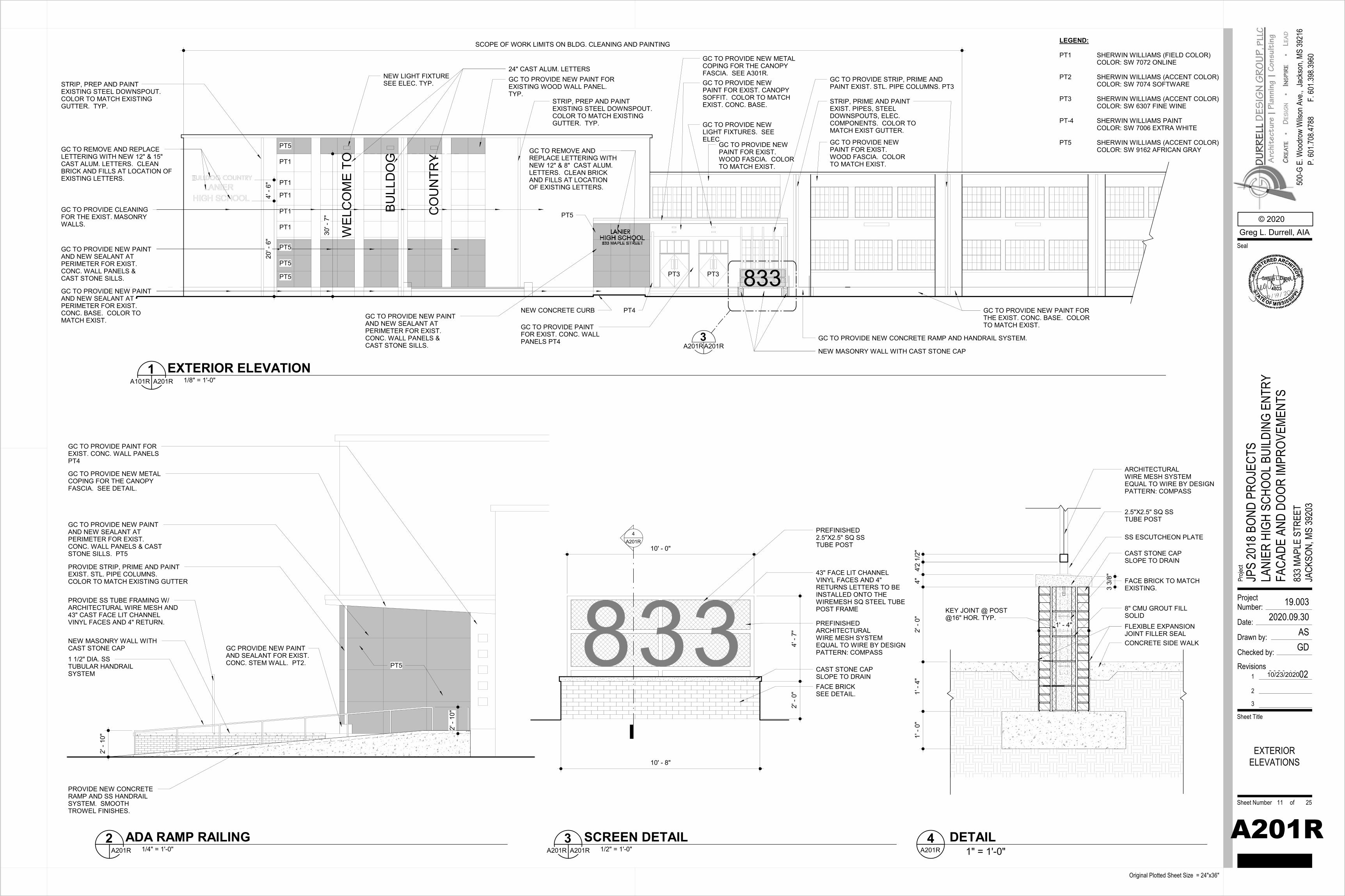
GC TO REMOVE AND REPLACE LETTERING WITH NEW 12" & 15" CAST ALUM. LETTERS. CLEAN BRICK AND FILLS AT LOCATION OF EXISTING LETTERS.
GC TO PROVIDE NEW PAINT AND NEW SEALANT AT PERIMETER FOR EXIST. CONC. WALL PANELS & CAST STONE SILLS.
WEL
CO
ME
TO
BULL
DO
G
CO
UN
TRY
NEW CONCRETE CURB
NEW MASONRY WALL WITH CAST STONE CAP
GC TO PROVIDE NEW METAL COPING FOR THE CANOPY FASCIA. SEE A301R.GC TO PROVIDE NEW PAINT FOR EXIST. CANOPY SOFFIT. COLOR TO MATCHEXIST. CONC. BASE.
GC TO PROVIDE NEW LIGHT FIXTURES. SEE ELEC.
GC TO PROVIDE STRIP, PRIME AND PAINT EXIST. STL. PIPE COLUMNS. PT3
GC TO PROVIDE NEW CONCRETE RAMP AND HANDRAIL SYSTEM.
24" CAST ALUM. LETTERS
GC TO PROVIDE PAINT FOR EXIST. CONC. WALL PANELS PT4 3
A201RA201R
GC TO PROVIDE NEW PAINT FOR EXISTING WOOD WALL PANEL. TYP.
NEW LIGHT FIXTURESEE ELEC. TYP.STRIP, PREP AND PAINT
EXISTING STEEL DOWNSPOUT.COLOR TO MATCH EXISTING GUTTER. TYP.
SCOPE OF WORK LIMITS ON BLDG. CLEANING AND PAINTING
833
STRIP, PRIME AND PAINTEXIST. PIPES, STEEL DOWNSPOUTS, ELEC. COMPONENTS. COLOR TO MATCH EXIST GUTTER.
GC TO REMOVE AND REPLACE LETTERING WITH NEW 12" & 8" CAST ALUM. LETTERS. CLEAN BRICK AND FILLS AT LOCATION OF EXISTING LETTERS.
PT5 GC TO PROVIDE NEW PAINT FOR EXIST. WOOD FASCIA. COLOR TO MATCH EXIST.
GC TO PROVIDE NEW PAINT FOR EXIST. WOOD FASCIA. COLOR TO MATCH EXIST.
GC TO PROVIDE NEW PAINT AND NEW SEALANT AT PERIMETER FOR EXIST. CONC. BASE. COLOR TO MATCH EXIST.
GC TO PROVIDE NEW PAINT FOR THE EXIST. CONC. BASE. COLOR TO MATCH EXIST.
PT5
GC TO PROVIDE NEW PAINT AND NEW SEALANT AT PERIMETER FOR EXIST. CONC. WALL PANELS & CAST STONE SILLS.
PT3 PT3
GC TO PROVIDE CLEANING FOR THE EXIST. MASONRY WALLS.
PT1
STRIP, PREP AND PAINTEXISTING STEEL DOWNSPOUT.COLOR TO MATCH EXISTING GUTTER. TYP.
4' -
6"20
' - 6
"
30' -
7"
PT4
PT5
PT5
PT5
PT1
PT1
PT1
PT1
GC TO PROVIDE NEW METAL COPING FOR THE CANOPY FASCIA. SEE DETAIL.
PROVIDE STRIP, PRIME AND PAINT EXIST. STL. PIPE COLUMNS.COLOR TO MATCH EXISTING GUTTER
PROVIDE SS TUBE FRAMING W/ ARCHITECTURAL WIRE MESH AND 43" CAST FACE LIT CHANNELVINYL FACES AND 4" RETURN.
GC TO PROVIDE NEW PAINT AND NEW SEALANT AT PERIMETER FOR EXIST. CONC. WALL PANELS & CAST STONE SILLS. PT5
NEW MASONRY WALL WITH CAST STONE CAP
PROVIDE NEW CONCRETE RAMP AND SS HANDRAIL SYSTEM. SMOOTH TROWEL FINISHES.
GC TO PROVIDE PAINT FOR EXIST. CONC. WALL PANELSPT4
1 1/2" DIA. SS TUBULAR HANDRAIL SYSTEM
GC PROVIDE NEW PAINTAND SEALANT FOR EXIST.CONC. STEM WALL. PT2. PT5
2' -
10"
2' -
10"
4' -
7"2'
- 0"
10' - 8"
4A201R
43" FACE LIT CHANNEL VINYL FACES AND 4" RETURNS LETTERS TO BE INSTALLED ONTO THE WIREMESH SQ STEEL TUBE POST FRAME
PREFINISHEDARCHITECTURALWIRE MESH SYSTEMEQUAL TO WIRE BY DESIGNPATTERN: COMPASS
10' - 0"
PREFINISHED2.5"X2.5" SQ SSTUBE POST
CAST STONE CAPSLOPE TO DRAINFACE BRICKSEE DETAIL.
4"4"
2' -
0"1'
- 4"
1' -
0"2
1/2" CAST STONE CAP
SLOPE TO DRAIN
FACE BRICK TO MATCHEXISTING.
8" CMU GROUT FILLSOLID
CONCRETE SIDE WALK
FLEXIBLE EXPANSIONJOINT FILLER SEAL
2.5"X2.5" SQ SSTUBE POST
ARCHITECTURALWIRE MESH SYSTEMEQUAL TO WIRE BY DESIGNPATTERN: COMPASS
SS ESCUTCHEON PLATE
KEY JOINT @ POST@16" HOR. TYP.
1' - 4"
3 3/
8"
ProjectNumber:
Date:
Drawn by:
Checked by:
Sheet Number of
Sheet Title
Proje
ct
Original Plotted Sheet Size = 24"x36"
© 2020Greg L. Durrell, AIA
500-
G E.
Woo
drow
Wils
on A
ve.,
Seal
Jack
son,
MS 39
216
P. 60
1.708
.4788
F. 60
1.398
.3960
Revisions1
2
3
2020.11.02
19.0032020.09.30
ASGD
A201R
JPS
2018
BON
D PR
OJEC
TSLA
NIER
HIG
H SC
HOOL
BUI
LDIN
G EN
TRY
FACA
DE A
ND D
OOR
IMPR
OVEM
ENTS
833 M
APLE
STR
EET
JACK
SON,
MS
3920
3
EXTERIORELEVATIONS
11 25
1/8" = 1'-0"A101R A201R1 EXTERIOR ELEVATION
1/4" = 1'-0"A201R2 ADA RAMP RAILING
1/2" = 1'-0"A201R A201R3 SCREEN DETAIL
1" = 1'-0"A201R4 DETAIL
10/23/2020
LEGEND:
PT1 SHERWIN WILLIAMS (FIELD COLOR)COLOR: SW 7072 ONLINE
PT2 SHERWIN WILLIAMS (ACCENT COLOR)COLOR: SW 7074 SOFTWARE
PT3 SHERWIN WILLIAMS (ACCENT COLOR)COLOR: SW 6307 FINE WINE
PT-4 SHERWIN WILLIAMS PAINT COLOR: SW 7006 EXTRA WHITE
PT5 SHERWIN WILLIAMS (ACCENT COLOR)COLOR: SW 9162 AFRICAN GRAY
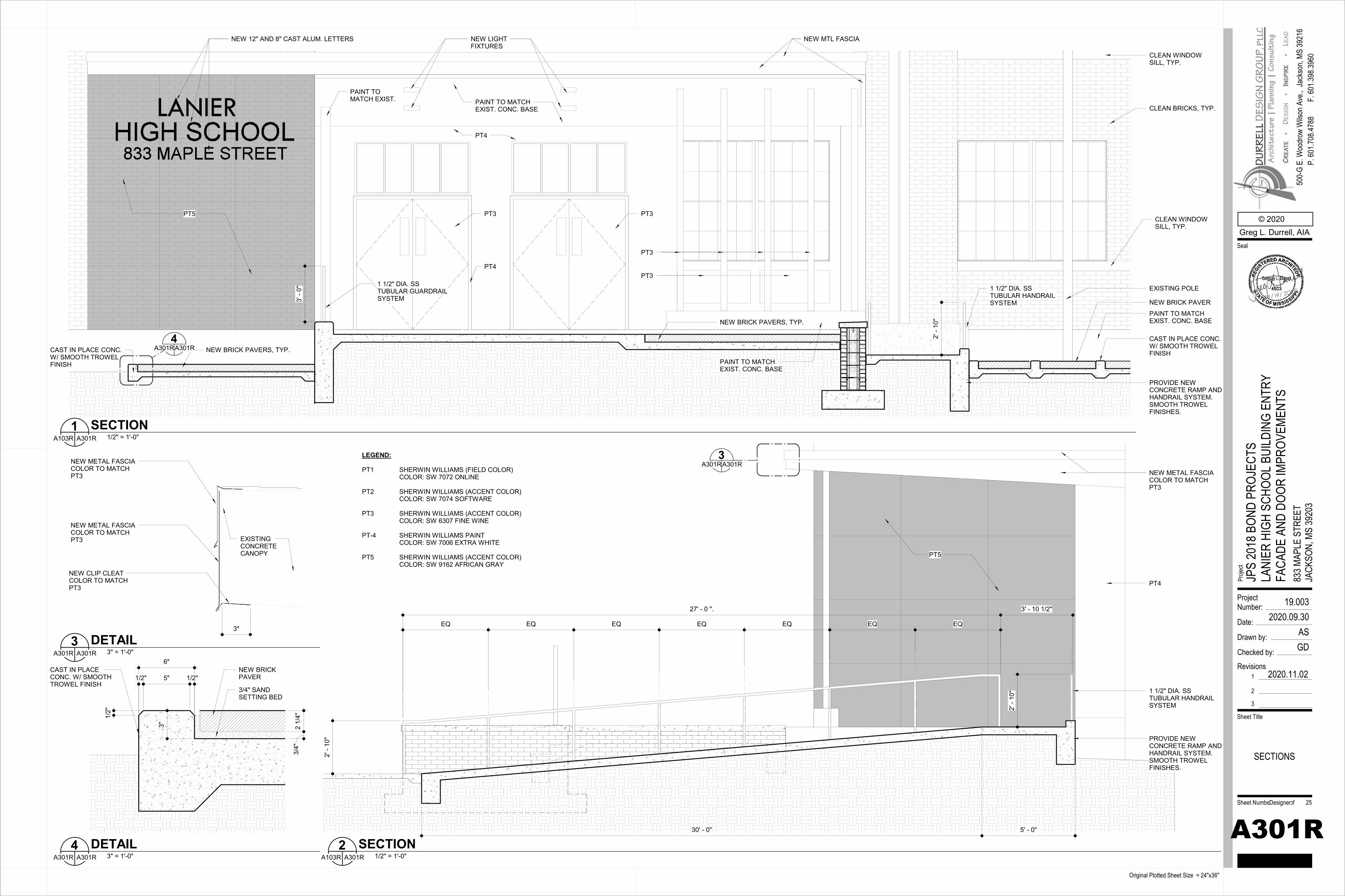
EXISTING POLE
NEW BRICK PAVER
CAST IN PLACE CONC.W/ SMOOTH TROWEL FINISH
PROVIDE NEW CONCRETE RAMP AND HANDRAIL SYSTEM. SMOOTH TROWEL FINISHES.
1 1/2" DIA. SS TUBULAR HANDRAIL SYSTEM
NEW BRICK PAVERS, TYP.
1 1/2" DIA. SS TUBULAR GUARDRAIL SYSTEM
NEW BRICK PAVERS, TYP.CAST IN PLACE CONC.W/ SMOOTH TROWEL FINISH
4A301RA301R
NEW MTL FASCIA
PT5
PAINT TO MATCHEXIST. CONC. BASE
NEW LIGHTFIXTURES
NEW 12" AND 8" CAST ALUM. LETTERS
3' -
0"
PAINT TO MATCH EXIST.
PT3 PT3
CLEAN BRICKS, TYP.
CLEAN WINDOWSILL, TYP.
CLEAN WINDOWSILL, TYP.
PT4
PT4
PT3
PAINT TO MATCHEXIST. CONC. BASE
PT3
PAINT TO MATCHEXIST. CONC. BASE
2' -
10"
27' - 0 ". 3' - 10 1/2"
PROVIDE NEW CONCRETE RAMP AND HANDRAIL SYSTEM. SMOOTH TROWEL FINISHES.
1 1/2" DIA. SS TUBULAR HANDRAIL SYSTEM
3A301RA301R
NEW METAL FASCIACOLOR TO MATCHPT3
30' - 0" 5' - 0"
EQ EQ EQ EQ EQ EQ EQ
PT5
2' -
10"
2' -
10"
PT4
NEW METAL FASCIACOLOR TO MATCHPT3
3"
NEW CLIP CLEATCOLOR TO MATCH PT3
NEW METAL FASCIACOLOR TO MATCHPT3 EXISTING
CONCRETECANOPY
NEW BRICK PAVER
CAST IN PLACE CONC. W/ SMOOTH TROWEL FINISH
6"
1/2"5"1/2"
2 1/
4"3/
4"
3"
3/4" SAND SETTING BED
1/2"
ProjectNumber:
Date:
Drawn by:
Checked by:
Sheet Number of
Sheet Title
Proje
ct
Original Plotted Sheet Size = 24"x36"
© 2020Greg L. Durrell, AIA
500-
G E.
Woo
drow
Wils
on A
ve.,
Seal
Jack
son,
MS 39
216
P. 60
1.708
.4788
F. 60
1.398
.3960
Revisions1
2
3
2020.11.02
19.0032020.09.30
ASGD
A301R
JPS
2018
BON
D PR
OJEC
TSLA
NIER
HIG
H SC
HOOL
BUI
LDIN
G EN
TRY
FACA
DE A
ND D
OOR
IMPR
OVEM
ENTS
833 M
APLE
STR
EET
JACK
SON,
MS
3920
3
SECTIONS
Designer 25
1/2" = 1'-0"A103R A301R1 SECTION
1/2" = 1'-0"A103R A301R2 SECTION
3" = 1'-0"A301R A301R3 DETAIL
3" = 1'-0"A301R A301R4 DETAIL
LEGEND:
PT1 SHERWIN WILLIAMS (FIELD COLOR)COLOR: SW 7072 ONLINE
PT2 SHERWIN WILLIAMS (ACCENT COLOR)COLOR: SW 7074 SOFTWARE
PT3 SHERWIN WILLIAMS (ACCENT COLOR)COLOR: SW 6307 FINE WINE
PT-4 SHERWIN WILLIAMS PAINT COLOR: SW 7006 EXTRA WHITE
PT5 SHERWIN WILLIAMS (ACCENT COLOR)COLOR: SW 9162 AFRICAN GRAY
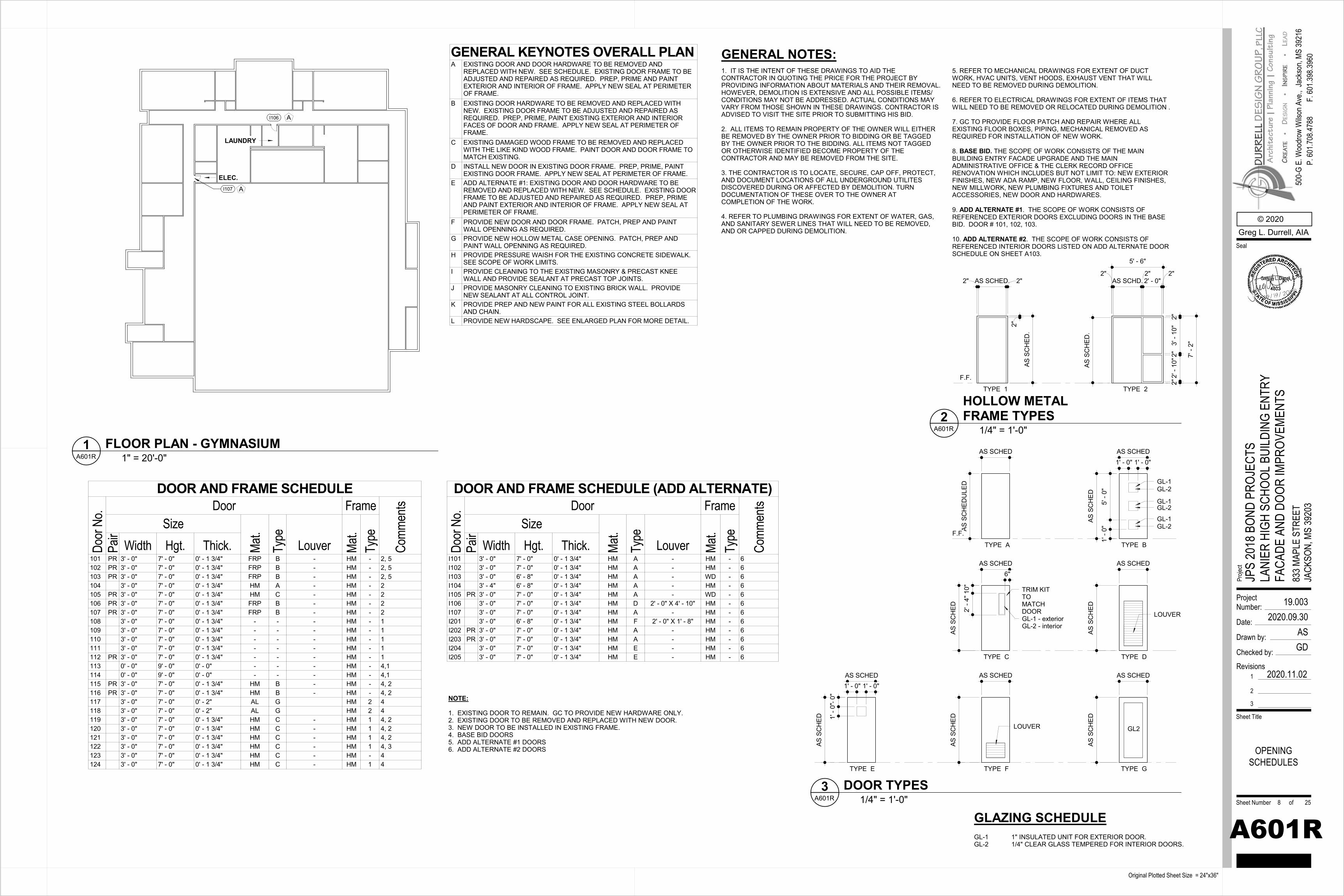
ELEC.
LAUNDRY
I107
I106 A
A
1. IT IS THE INTENT OF THESE DRAWINGS TO AID THE CONTRACTOR IN QUOTING THE PRICE FOR THE PROJECT BY PROVIDING INFORMATION ABOUT MATERIALS AND THEIR REMOVAL. HOWEVER, DEMOLITION IS EXTENSIVE AND ALL POSSIBLE ITEMS/ CONDITIONS MAY NOT BE ADDRESSED. ACTUAL CONDITIONS MAY VARY FROM THOSE SHOWN IN THESE DRAWINGS. CONTRACTOR IS ADVISED TO VISIT THE SITE PRIOR TO SUBMITTING HIS BID.
2. ALL ITEMS TO REMAIN PROPERTY OF THE OWNER WILL EITHER BE REMOVED BY THE OWNER PRIOR TO BIDDING OR BE TAGGED BY THE OWNER PRIOR TO THE BIDDING. ALL ITEMS NOT TAGGED OR OTHERWISE IDENTIFIED BECOME PROPERTY OF THE CONTRACTOR AND MAY BE REMOVED FROM THE SITE.
3. THE CONTRACTOR IS TO LOCATE, SECURE, CAP OFF, PROTECT, AND DOCUMENT LOCATIONS OF ALL UNDERGROUND UTILITES DISCOVERED DURING OR AFFECTED BY DEMOLITION. TURN DOCUMENTATION OF THESE OVER TO THE OWNER AT COMPLETION OF THE WORK.
4. REFER TO PLUMBING DRAWINGS FOR EXTENT OF WATER, GAS, AND SANITARY SEWER LINES THAT WILL NEED TO BE REMOVED, AND OR CAPPED DURING DEMOLITION.
GENERAL NOTES:5. REFER TO MECHANICAL DRAWINGS FOR EXTENT OF DUCT WORK, HVAC UNITS, VENT HOODS, EXHAUST VENT THAT WILL NEED TO BE REMOVED DURING DEMOLITION.
6. REFER TO ELECTRICAL DRAWINGS FOR EXTENT OF ITEMS THATWILL NEED TO BE REMOVED OR RELOCATED DURING DEMOLITION .
7. GC TO PROVIDE FLOOR PATCH AND REPAIR WHERE ALL EXISTING FLOOR BOXES, PIPING, MECHANICAL REMOVED AS REQUIRED FOR INSTALLATION OF NEW WORK.
8. BASE BID. THE SCOPE OF WORK CONSISTS OF THE MAIN BUILDING ENTRY FACADE UPGRADE AND THE MAIN ADMINISTRATIVE OFFICE & THE CLERK RECORD OFFICE RENOVATION WHICH INCLUDES BUT NOT LIMIT TO: NEW EXTERIOR FINISHES, NEW ADA RAMP, NEW FLOOR, WALL, CEILING FINISHES, NEW MILLWORK, NEW PLUMBING FIXTURES AND TOILET ACCESSORIES, NEW DOOR AND HARDWARES.
9. ADD ALTERNATE #1. THE SCOPE OF WORK CONSISTS OF REFERENCED EXTERIOR DOORS EXCLUDING DOORS IN THE BASE BID. DOOR # 101, 102, 103.
10. ADD ALTERNATE #2. THE SCOPE OF WORK CONSISTS OF REFERENCED INTERIOR DOORS LISTED ON ADD ALTERNATE DOOR SCHEDULE ON SHEET A103.
AS S
CH
EDU
LED
AS SCHED
TYPE A
F.F.
TYPE B
AS SCHED
AS S
CH
ED
5' -
0"1'
- 0"
GL-1
1' - 0" 1' - 0"
GL-1
GL-1
TYPE C
AS SCHED
AS S
CH
ED
6"
10"
2' -
4"
GL-1 - exteriorGL-2 - interior
TRIM KIT TO MATCH DOOR
TYPE D
AS SCHED
AS S
CH
ED
LOUVER
TYPE E
AS SCHED
AS S
CH
ED
1' - 0" 1' - 0"
1' -
0"1'
- 0"
TYPE F
AS SCHED
AS S
CH
ED
LOUVER
GL-2
GL-2
GL-2
TYPE G
AS SCHED
AS S
CH
ED
GL2
AS S
CH
ED.
TYPE 1
F.F.
2"
TYPE 2
2"AS SCHD.
2"2' - 0"
2"
2"3'
- 10
"2"
2' -
10"
2"
AS S
CH
ED.
2" AS SCHED. 2"
7' -
2"
5' - 6"
ProjectNumber:
Date:
Drawn by:
Checked by:
Sheet Number of
Sheet Title
Proje
ct
Original Plotted Sheet Size = 24"x36"
© 2020Greg L. Durrell, AIA
500-
G E.
Woo
drow
Wils
on A
ve.,
Seal
Jack
son,
MS 39
216
P. 60
1.708
.4788
F. 60
1.398
.3960
Revisions1
2
3
2020.11.02
19.0032020.09.30
ASGD
A601R
JPS
2018
BON
D PR
OJEC
TSLA
NIER
HIG
H SC
HOOL
BUI
LDIN
G EN
TRY
FACA
DE A
ND D
OOR
IMPR
OVEM
ENTS
833 M
APLE
STR
EET
JACK
SON,
MS
3920
3
OPENINGSCHEDULES
8 25
1" = 20'-0"A601R1 FLOOR PLAN - GYMNASIUM
DOOR AND FRAME SCHEDULE
Door
No. Door Frame
Comm
ents
Size
Mat.
Type Louver Mat.
Type
Pair
Width Hgt. Thick.101 PR 3' - 0" 7' - 0" 0' - 1 3/4" FRP B - HM - 2, 5102 PR 3' - 0" 7' - 0" 0' - 1 3/4" FRP B - HM - 2, 5103 PR 3' - 0" 7' - 0" 0' - 1 3/4" FRP B - HM - 2, 5104 3' - 0" 7' - 0" 0' - 1 3/4" HM A - HM - 2105 PR 3' - 0" 7' - 0" 0' - 1 3/4" HM C - HM - 2106 PR 3' - 0" 7' - 0" 0' - 1 3/4" FRP B - HM - 2107 PR 3' - 0" 7' - 0" 0' - 1 3/4" FRP B - HM - 2108 3' - 0" 7' - 0" 0' - 1 3/4" - - - HM - 1109 3' - 0" 7' - 0" 0' - 1 3/4" - - - HM - 1110 3' - 0" 7' - 0" 0' - 1 3/4" - - - HM - 1111 3' - 0" 7' - 0" 0' - 1 3/4" - - - HM - 1112 PR 3' - 0" 7' - 0" 0' - 1 3/4" - - - HM - 1113 0' - 0" 9' - 0" 0' - 0" - - - HM - 4,1114 0' - 0" 9' - 0" 0' - 0" - - - HM - 4,1115 PR 3' - 0" 7' - 0" 0' - 1 3/4" HM B - HM - 4, 2116 PR 3' - 0" 7' - 0" 0' - 1 3/4" HM B - HM - 4, 2117 3' - 0" 7' - 0" 0' - 2" AL G HM 2 4118 3' - 0" 7' - 0" 0' - 2" AL G HM 2 4119 3' - 0" 7' - 0" 0' - 1 3/4" HM C - HM 1 4, 2120 3' - 0" 7' - 0" 0' - 1 3/4" HM C - HM 1 4, 2121 3' - 0" 7' - 0" 0' - 1 3/4" HM C - HM 1 4, 2122 3' - 0" 7' - 0" 0' - 1 3/4" HM C - HM 1 4, 3123 3' - 0" 7' - 0" 0' - 1 3/4" HM C - HM - 4124 3' - 0" 7' - 0" 0' - 1 3/4" HM C - HM 1 4
1/4" = 1'-0"A601R3 DOOR TYPES
GENERAL KEYNOTES OVERALL PLANA EXISTING DOOR AND DOOR HARDWARE TO BE REMOVED AND
REPLACED WITH NEW. SEE SCHEDULE. EXISTING DOOR FRAME TO BEADJUSTED AND REPAIRED AS REQUIRED. PREP, PRIME AND PAINTEXTERIOR AND INTERIOR OF FRAME. APPLY NEW SEAL AT PERIMETEROF FRAME.
B EXISTING DOOR HARDWARE TO BE REMOVED AND REPLACED WITHNEW. EXISTING DOOR FRAME TO BE ADJUSTED AND REPAIRED ASREQUIRED. PREP, PRIME, PAINT EXISTING EXTERIOR AND INTERIORFACES OF DOOR AND FRAME. APPLY NEW SEAL AT PERIMETER OFFRAME.
C EXISTING DAMAGED WOOD FRAME TO BE REMOVED AND REPLACEDWITH THE LIKE KIND WOOD FRAME. PAINT DOOR AND DOOR FRAME TOMATCH EXISTING.
D INSTALL NEW DOOR IN EXISTING DOOR FRAME. PREP, PRIME, PAINTEXISTING DOOR FRAME. APPLY NEW SEAL AT PERIMETER OF FRAME.
E ADD ALTERNATE #1: EXISTING DOOR AND DOOR HARDWARE TO BEREMOVED AND REPLACED WITH NEW. SEE SCHEDULE. EXISTING DOORFRAME TO BE ADJUSTED AND REPAIRED AS REQUIRED. PREP, PRIMEAND PAINT EXTERIOR AND INTERIOR OF FRAME. APPLY NEW SEAL ATPERIMETER OF FRAME.
F PROVIDE NEW DOOR AND DOOR FRAME. PATCH, PREP AND PAINTWALL OPENNING AS REQUIRED.
G PROVIDE NEW HOLLOW METAL CASE OPENING. PATCH, PREP ANDPAINT WALL OPENNING AS REQUIRED.
H PROVIDE PRESSURE WAISH FOR THE EXISTING CONCRETE SIDEWALK.SEE SCOPE OF WORK LIMITS.
I PROVIDE CLEANING TO THE EXISTING MASONRY & PRECAST KNEEWALL AND PROVIDE SEALANT AT PRECAST TOP JOINTS.
J PROVIDE MASONRY CLEANING TO EXISTING BRICK WALL. PROVIDENEW SEALANT AT ALL CONTROL JOINT.
K PROVIDE PREP AND NEW PAINT FOR ALL EXISTING STEEL BOLLARDSAND CHAIN.
L PROVIDE NEW HARDSCAPE. SEE ENLARGED PLAN FOR MORE DETAIL.
GLAZING SCHEDULEGL-1 1" INSULATED UNIT FOR EXTERIOR DOOR.GL-2 1/4" CLEAR GLASS TEMPERED FOR INTERIOR DOORS.
DOOR AND FRAME SCHEDULE (ADD ALTERNATE)
Door
No. Door Frame
Comm
ents
Size
Mat.
Type Louver Mat.
Type
Pair
Width Hgt. Thick.I101 3' - 0" 7' - 0" 0' - 1 3/4" HM A - HM - 6I102 3' - 0" 7' - 0" 0' - 1 3/4" HM A - HM - 6I103 3' - 0" 6' - 8" 0' - 1 3/4" HM A - WD - 6I104 3' - 4" 6' - 8" 0' - 1 3/4" HM A - HM - 6I105 PR 3' - 0" 7' - 0" 0' - 1 3/4" HM A - WD - 6I106 3' - 0" 7' - 0" 0' - 1 3/4" HM D 2' - 0" X 4' - 10" HM - 6I107 3' - 0" 7' - 0" 0' - 1 3/4" HM A - HM - 6I201 3' - 0" 6' - 8" 0' - 1 3/4" HM F 2' - 0" X 1' - 8" HM - 6I202 PR 3' - 0" 7' - 0" 0' - 1 3/4" HM A - HM - 6I203 PR 3' - 0" 7' - 0" 0' - 1 3/4" HM A - HM - 6I204 3' - 0" 7' - 0" 0' - 1 3/4" HM E - HM - 6I205 3' - 0" 7' - 0" 0' - 1 3/4" HM E - HM - 6
NOTE:
1. EXISTING DOOR TO REMAIN. GC TO PROVIDE NEW HARDWARE ONLY.2. EXISTING DOOR TO BE REMOVED AND REPLACED WITH NEW DOOR.3. NEW DOOR TO BE INSTALLED IN EXISTING FRAME.4. BASE BID DOORS5. ADD ALTERNATE #1 DOORS6. ADD ALTERNATE #2 DOORS
1/4" = 1'-0"A601R2
HOLLOW METALFRAME TYPES
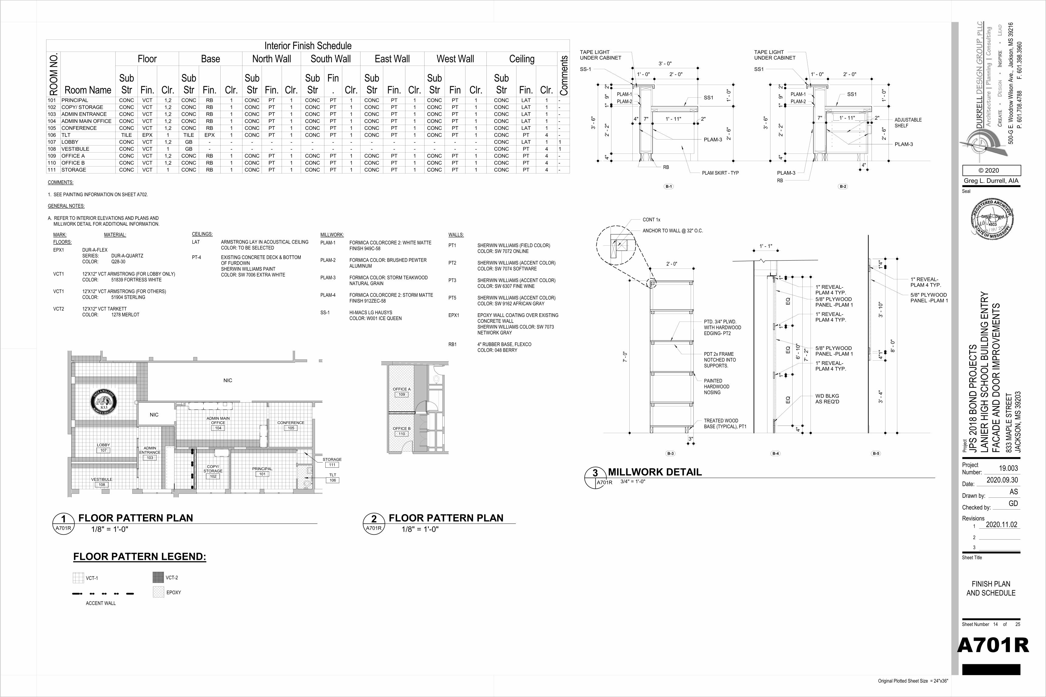
FLOORS:MARK: MATERIAL:
EPX1 DUR-A-FLEXSERIES: DUR-A-QUARTZCOLOR: Q28-30
CEILINGS:
PT-4 EXISTING CONCRETE DECK & BOTTOM OF FURDOWNSHERWIN WILLIAMS PAINT COLOR: SW 7006 EXTRA WHITE
A. REFER TO INTERIOR ELEVATIONS AND PLANS AND MILLWORK DETAIL FOR ADDITIONAL INFORMATION.
GENERAL NOTES:
1. SEE PAINTING INFORMATION ON SHEET A702.
COMMENTS:
WALLS:MILLWORK:PLAM-1 FORMICA COLORCORE 2: WHITE MATTE
FINISH 949C-58
PLAM-2 FORMICA COLOR: BRUSHED PEWTER ALUMINUM
PLAM-3 FORMICA COLOR: STORM TEAKWOODNATURAL GRAIN
PLAM-4 FORMICA COLORCORE 2: STORM MATTE FINISH 912ZEC-58
SS-1 HI-MACS LG HAUSYSCOLOR: W001 ICE QUEEN
LAT ARMSTRONG LAY IN ACOUSTICAL CEILINGCOLOR: TO BE SELECTED PT1 SHERWIN WILLIAMS (FIELD COLOR)
COLOR: SW 7072 ONLINE
PT2 SHERWIN WILLIAMS (ACCENT COLOR)COLOR: SW 7074 SOFTWARE
PT3 SHERWIN WILLIAMS (ACCENT COLOR)COLOR: SW 6307 FINE WINE
PT5 SHERWIN WILLIAMS (ACCENT COLOR)COLOR: SW 9162 AFRICAN GRAY
EPX1 EPOXY WALL COATING OVER EXISTING CONCRETE WALLSHERWIN WILLIAMS COLOR: SW 7073 NETWORK GRAY
RB1 4" RUBBER BASE, FLEXCOCOLOR: 048 BERRY
VCT1 12'X12" VCT ARMSTRONG (FOR LOBBY ONLY)COLOR: 51839 FORTRESS WHITE
VCT1 12'X12" VCT ARMSTRONG (FOR OTHERS)COLOR: 51904 STERLING
VCT2 12'X12" VCT TARKETTCOLOR: 1278 MERLOT
LOBBY107
NIC
NIC
ADMINENTRANCE
103
ADMIN MAINOFFICE
104
COPY/STORAGE
102
PRINCIPAL101
CONFERENCE105
VESTIBULE108
TLT106
STORAGE111
OFFICE A109
OFFICE B110
FLOOR PATTERN LEGEND:
VCT-1
ACCENT WALL
VCT-2
EPOXY
1' -
0"
4" 7" 1' - 11" 2"
2' -
6"
SS-1
PLAM-3
PLAM-3
ADJUSTABLE SHELF
4"RB
3' - 0"
4"2'
- 2"
1"9"
2"
1' - 0" 2' - 0"
PLAM-2 1' -
0"
7" 1' - 11" 2"
2' -
6"
SS1
PLAM-3
RB
4"2'
- 2"
1"9"
2"
1' - 0" 2' - 0"
PLAM-2
PLAM SKIRT - TYP
3' -
6"
3' -
6"
B-1 B-2
PLAM-1 PLAM-1
TAPE LIGHT UNDER CABINET
TAPE LIGHT UNDER CABINET
SS1 SS1
2' - 0"
7' - 0
"
PTD. 3/4" PLWD. WITH HARDWOOD EDGING- PT2
PDT 2x FRAME NOTCHED INTO SUPPORTS.
PAINTED HARDWOOD NOSING
TREATED WOOD BASE (TYPICAL), PT1
ANCHOR TO WALL @ 32" O.C.
CONT 1x
3"
B-3 B-4
5/8" PLYWOOD PANEL -PLAM 1
1" REVEAL-PLAM 4 TYP.
WD BLKGAS REQ'D
B-5
1' - 1"
EQEQ
EQ1"
1"
7' -
2"4"
6' -
10"
5/8" PLYWOOD PANEL -PLAM 1
1" REVEAL-PLAM 4 TYP.
1" REVEAL-PLAM 4 TYP.
1"
8' -
0"
4"1"
3' -
10"
1"4"
3' -
4"
5/8" PLYWOOD PANEL -PLAM 1
1" REVEAL-PLAM 4 TYP.
ProjectNumber:
Date:
Drawn by:
Checked by:
Sheet Number of
Sheet Title
Proje
ct
Original Plotted Sheet Size = 24"x36"
© 2020Greg L. Durrell, AIA
500-
G E.
Woo
drow
Wils
on A
ve.,
Seal
Jack
son,
MS 39
216
P. 60
1.708
.4788
F. 60
1.398
.3960
Revisions1
2
3
2020.11.02
19.0032020.09.30
ASGD
A701R
JPS
2018
BON
D PR
OJEC
TSLA
NIER
HIG
H SC
HOOL
BUI
LDIN
G EN
TRY
FACA
DE A
ND D
OOR
IMPR
OVEM
ENTS
833 M
APLE
STR
EET
JACK
SON,
MS
3920
3
FINISH PLANAND SCHEDULE
14 25
Interior Finish ScheduleRO
OM N
O.
Room Name
Floor Base North Wall South Wall East Wall West Wall Ceiling
Comm
ents
SubStr Fin. Clr.
SubStr Fin. Clr.
SubStr Fin. Clr.
SubStr
Fin. Clr.
SubStr Fin. Clr.
SubStr Fin Clr.
SubStr Fin. Clr.
101 PRINCIPAL CONC VCT 1,2 CONC RB 1 CONC PT 1 CONC PT 1 CONC PT 1 CONC PT 1 CONC LAT 1 -102 COPY/ STORAGE CONC VCT 1,2 CONC RB 1 CONC PT 1 CONC PT 1 CONC PT 1 CONC PT 1 CONC LAT 1 -103 ADMIN ENTRANCE CONC VCT 1,2 CONC RB 1 CONC PT 1 CONC PT 1 CONC PT 1 CONC PT 1 CONC LAT 1 -104 ADMIN MAIN OFFICE CONC VCT 1,2 CONC RB 1 CONC PT 1 CONC PT 1 CONC PT 1 CONC PT 1 CONC LAT 1 -105 CONFERENCE CONC VCT 1,2 CONC RB 1 CONC PT 1 CONC PT 1 CONC PT 1 CONC PT 1 CONC LAT 1 -106 TLT TILE EPX 1 TILE EPX 1 CONC PT 1 CONC PT 1 CONC PT 1 CONC PT 1 CONC PT 4 -107 LOBBY CONC VCT 1,2 GB - - - - - - - - - - - - - - CONC LAT 1 1108 VESTIBULE CONC VCT 1 GB - - - - - - - - - - - - - - CONC PT 4 1109 OFFICE A CONC VCT 1,2 CONC RB 1 CONC PT 1 CONC PT 1 CONC PT 1 CONC PT 1 CONC PT 4 -110 OFFICE B CONC VCT 1,2 CONC RB 1 CONC PT 1 CONC PT 1 CONC PT 1 CONC PT 1 CONC PT 4 -111 STORAGE CONC VCT 1 CONC RB 1 CONC PT 1 CONC PT 1 CONC PT 1 CONC PT 1 CONC PT 4 -
1/8" = 1'-0"A701R1 FLOOR PATTERN PLAN
1/8" = 1'-0"A701R2 FLOOR PATTERN PLAN
3/4" = 1'-0"A701R3 MILLWORK DETAIL
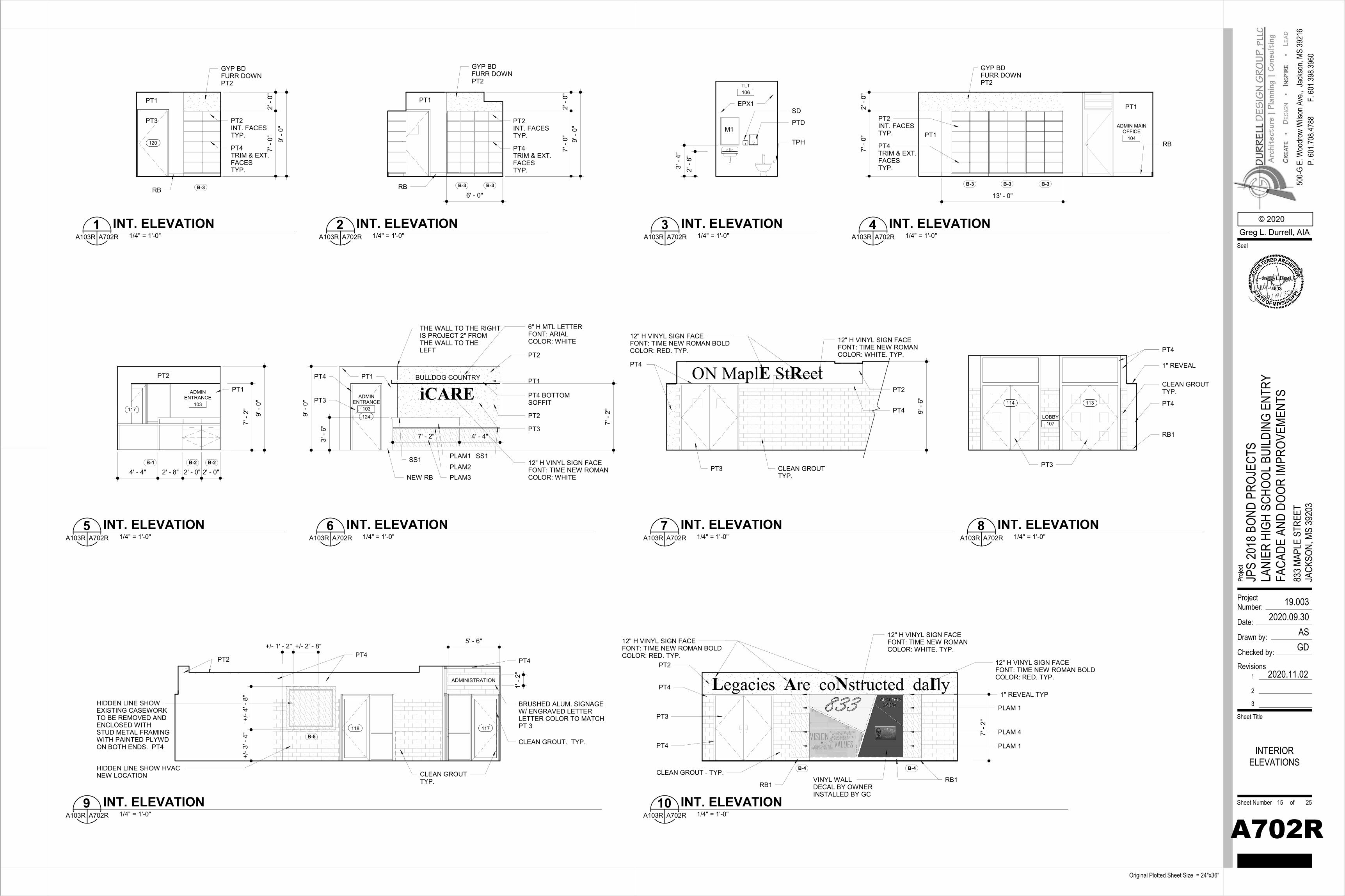
120
B-3
GYP BD FURR DOWNPT2
PT1
9' -
0"2'
- 0"
7' -
0"
PT2INT. FACESTYP.
PT4TRIM & EXT.FACESTYP.
RB
PT3
6' - 0"B-3 B-3
9' -
0"
GYP BD FURR DOWNPT2
PT1
RB
PT2INT. FACESTYP.
PT4TRIM & EXT.FACESTYP.
7' -
0"2'
- 0"
2' -
8"3'
- 4"
M1
SD
PTD
TPH
TLT106
EPX1
ADMIN MAINOFFICE
104
GYP BD FURR DOWNPT2
PT1
RB
13' - 0"
B-3 B-3 B-3
2' -
0"7'
- 0"
PT2INT. FACESTYP.
PT4TRIM & EXT.FACESTYP.
PT1
3' -
6"
PT2
NEW RB
SS1PLAM1PLAM2
ADMINENTRANCE
103
PLAM3
BULLDOG COUNTRY PT1
PT4 BOTTOM SOFFIT
PT1
6" H MTL LETTERFONT: ARIAL COLOR: WHITE
1249' -
0"
7' - 2" 4' - 4"
iCARE
12" H VINYL SIGN FACEFONT: TIME NEW ROMANCOLOR: WHITE
PT2
PT4
PT3
PT3
THE WALL TO THE RIGHTIS PROJECT 2" FROM THE WALL TO THE LEFT
7' -
2"
SS1B-2B-1
4' - 4" 2' - 8" 2' - 0" 2' - 0"
ADMINENTRANCE
103117
9' -
0"
7' -
2"
B-2
PT2
PT1
9' -
6"
CLEAN GROUT TYP.
PT2
PT4
PT4
ON MaplE StReet
12" H VINYL SIGN FACEFONT: TIME NEW ROMAN BOLDCOLOR: RED. TYP.
12" H VINYL SIGN FACEFONT: TIME NEW ROMANCOLOR: WHITE. TYP.
PT3
117118
PT4
CLEAN GROUTTYP.
CLEAN GROUT. TYP.
PT2 PT4
ADMINISTRATION
1' -
2"
BRUSHED ALUM. SIGNAGEW/ ENGRAVED LETTERLETTER COLOR TO MATCHPT 3
HIDDEN LINE SHOW EXISTING CASEWORK TO BE REMOVED AND ENCLOSED WITH STUD METAL FRAMING WITH PAINTED PLYWD ON BOTH ENDS. PT4
+/- 3
' - 4
"+/
- 4' -
8"
+/- 1' - 2" +/- 2' - 8"
B-5
HIDDEN LINE SHOW HVAC NEW LOCATION
5' - 6"
114 113
LOBBY107
PT4
PT4
CLEAN GROUTTYP.
1" REVEAL
PT3
RB1
PT2
1" REVEAL TYPPT4
CLEAN GROUT - TYP.
PT4
PT3
VINYL WALL DECAL BY OWNER INSTALLED BY GC
Legacies Are coNstructed daIly
12" H VINYL SIGN FACEFONT: TIME NEW ROMAN BOLDCOLOR: RED. TYP.
12" H VINYL SIGN FACEFONT: TIME NEW ROMANCOLOR: WHITE. TYP.
PLAM 1
12" H VINYL SIGN FACEFONT: TIME NEW ROMAN BOLDCOLOR: RED. TYP.
RB1RB1
B-4 B-4
PLAM 4
PLAM 1
7' -
2"
ProjectNumber:
Date:
Drawn by:
Checked by:
Sheet Number of
Sheet Title
Proje
ct
Original Plotted Sheet Size = 24"x36"
© 2020Greg L. Durrell, AIA
500-
G E.
Woo
drow
Wils
on A
ve.,
Seal
Jack
son,
MS 39
216
P. 60
1.708
.4788
F. 60
1.398
.3960
Revisions1
2
3
2020.11.02
19.0032020.09.30
ASGD
A702R
JPS
2018
BON
D PR
OJEC
TSLA
NIER
HIG
H SC
HOOL
BUI
LDIN
G EN
TRY
FACA
DE A
ND D
OOR
IMPR
OVEM
ENTS
833 M
APLE
STR
EET
JACK
SON,
MS
3920
3
INTERIORELEVATIONS
15 25
1/4" = 1'-0"A103R A702R1 INT. ELEVATION
1/4" = 1'-0"A103R A702R2 INT. ELEVATION
1/4" = 1'-0"A103R A702R3 INT. ELEVATION
1/4" = 1'-0"A103R A702R4 INT. ELEVATION
1/4" = 1'-0"A103R A702R6 INT. ELEVATION
1/4" = 1'-0"A103R A702R5 INT. ELEVATION
1/4" = 1'-0"A103R A702R7 INT. ELEVATION
1/4" = 1'-0"A103R A702R9 INT. ELEVATION
1/4" = 1'-0"A103R A702R8 INT. ELEVATION
1/4" = 1'-0"A103R A702R10 INT. ELEVATION
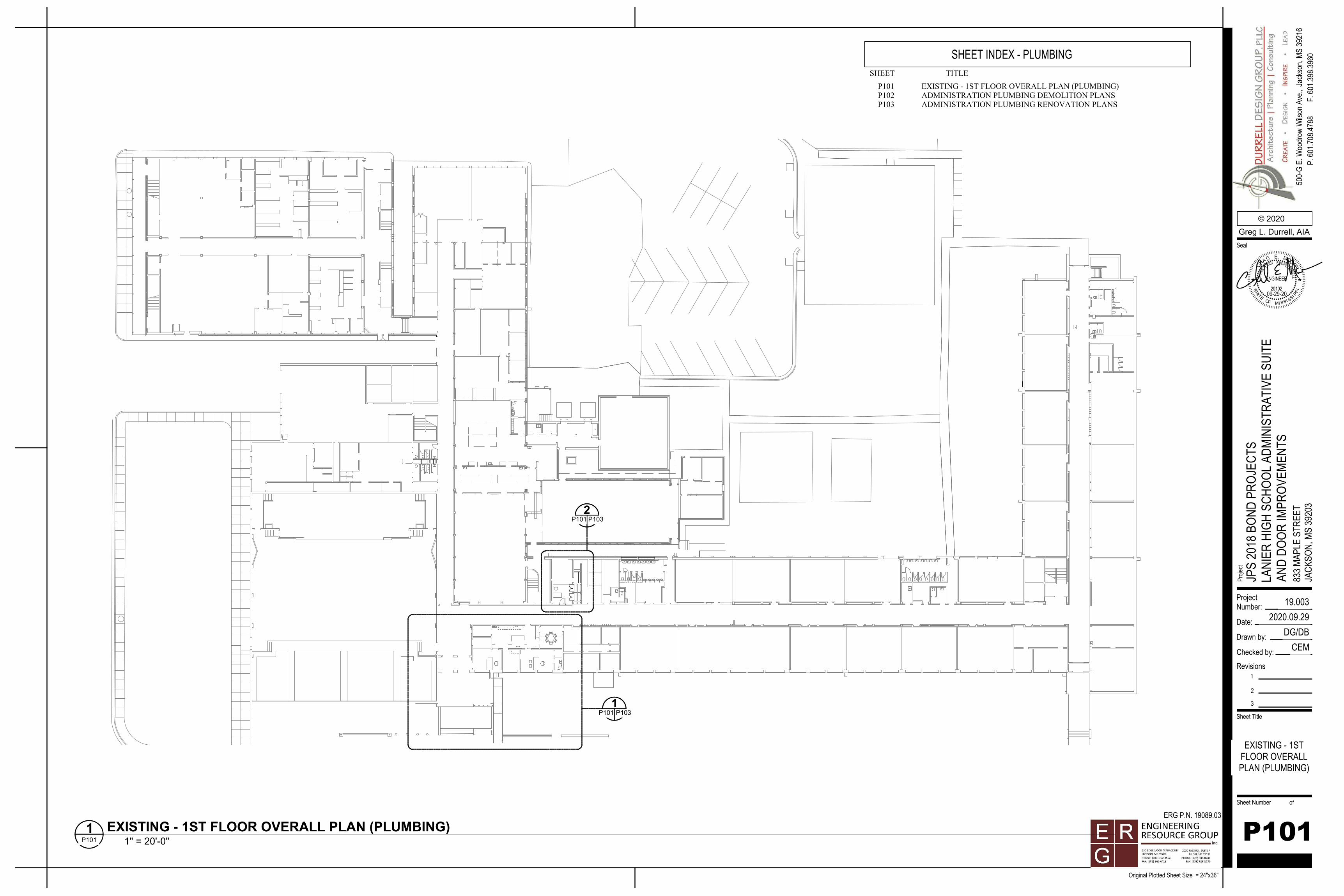
1P101 P103
2P101 P103
SHEET INDEX - PLUMBINGTITLESHEET
P101 EXISTING - 1ST FLOOR OVERALL PLAN (PLUMBING)P102 ADMINISTRATION PLUMBING DEMOLITION PLANSP103 ADMINISTRATION PLUMBING RENOVATION PLANS
ProjectNumber:
Date:
Drawn by:
Checked by:
Sheet Number of
Sheet Title
Proje
ct
Original Plotted Sheet Size = 24"x36"
© 2020
500-
G E.
Woo
drow
Wils
on A
ve.,
Seal
Jack
son,
MS 39
216
P. 60
1.708
.4788
F. 60
1.398
.3960
Revisions1
2
3
19.0032020.09.29
DG/DBCEM
JPS
2018
BON
D PR
OJEC
TSLA
NIER
HIG
H SC
HOOL
ADM
INIS
TRAT
IVE
SUIT
EAN
D DO
OR IM
PROV
EMEN
TS83
3 MAP
LE S
TREE
TJA
CKSO
N, M
S 39
203
ERG P.N. 19089.03
R
P
ETS
AT
SSIMOF I SS
20102
L
I PI
E
D
EGIS
T
A
CHME.
O
ENGINEER
P RRED
SIONA
FES ER
OO
09-29-20
P101
EXISTING - 1STFLOOR OVERALLPLAN (PLUMBING)
1" = 20'-0"P1011 EXISTING - 1ST FLOOR OVERALL PLAN (PLUMBING)
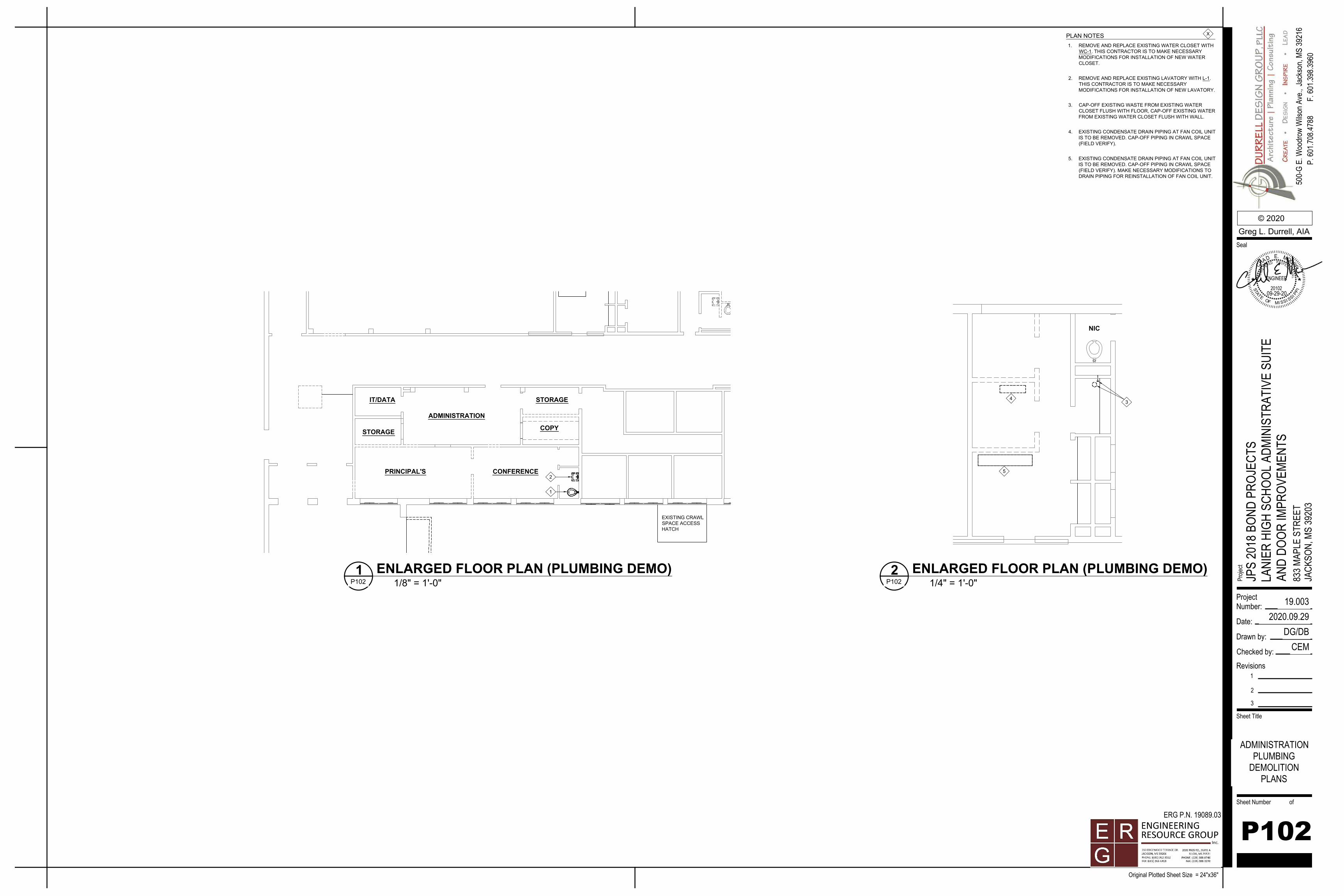
EXISTING CRAWLSPACE ACCESSHATCH
1
2
IT/DATA
STORAGE COPY
STORAGE
PRINCIPAL'S
ADMINISTRATION
CONFERENCE
NIC
34
5
PLAN NOTES 1. REMOVE AND REPLACE EXISTING WATER CLOSET WITH
WC-1. THIS CONTRACTOR IS TO MAKE NECESSARYMODIFICATIONS FOR INSTALLATION OF NEW WATERCLOSET.
2. REMOVE AND REPLACE EXISTING LAVATORY WITH L-1.THIS CONTRACTOR IS TO MAKE NECESSARYMODIFICATIONS FOR INSTALLATION OF NEW LAVATORY.
3. CAP-OFF EXISTING WASTE FROM EXISTING WATERCLOSET FLUSH WITH FLOOR, CAP-OFF EXISTING WATERFROM EXISTING WATER CLOSET FLUSH WITH WALL.
4. EXISTING CONDENSATE DRAIN PIPING AT FAN COIL UNITIS TO BE REMOVED. CAP-OFF PIPING IN CRAWL SPACE(FIELD VERIFY).
5. EXISTING CONDENSATE DRAIN PIPING AT FAN COIL UNITIS TO BE REMOVED. CAP-OFF PIPING IN CRAWL SPACE(FIELD VERIFY). MAKE NECESSARY MODIFICATIONS TODRAIN PIPING FOR REINSTALLATION OF FAN COIL UNIT.
X
ProjectNumber:
Date:
Drawn by:
Checked by:
Sheet Number of
Sheet Title
Proje
ct
Original Plotted Sheet Size = 24"x36"
© 2020
500-
G E.
Woo
drow
Wils
on A
ve.,
Seal
Jack
son,
MS 39
216
P. 60
1.708
.4788
F. 60
1.398
.3960
Revisions1
2
3
19.0032020.09.29
DG/DBCEM
JPS
2018
BON
D PR
OJEC
TSLA
NIER
HIG
H SC
HOOL
ADM
INIS
TRAT
IVE
SUIT
EAN
D DO
OR IM
PROV
EMEN
TS83
3 MAP
LE S
TREE
TJA
CKSO
N, M
S 39
203
ERG P.N. 19089.03
R
P
ET
SAT
SSIMOF I SS
20102
L
I PI
E
D
EGIS
T
A
CHME.
O
ENGINEER
P RRED
SIONA
FES ER
OO
09-29-20
P102
ADMINISTRATIONPLUMBING
DEMOLITIONPLANS
1/8" = 1'-0"P1021 ENLARGED FLOOR PLAN (PLUMBING DEMO)
1/4" = 1'-0"P1022 ENLARGED FLOOR PLAN (PLUMBING DEMO)
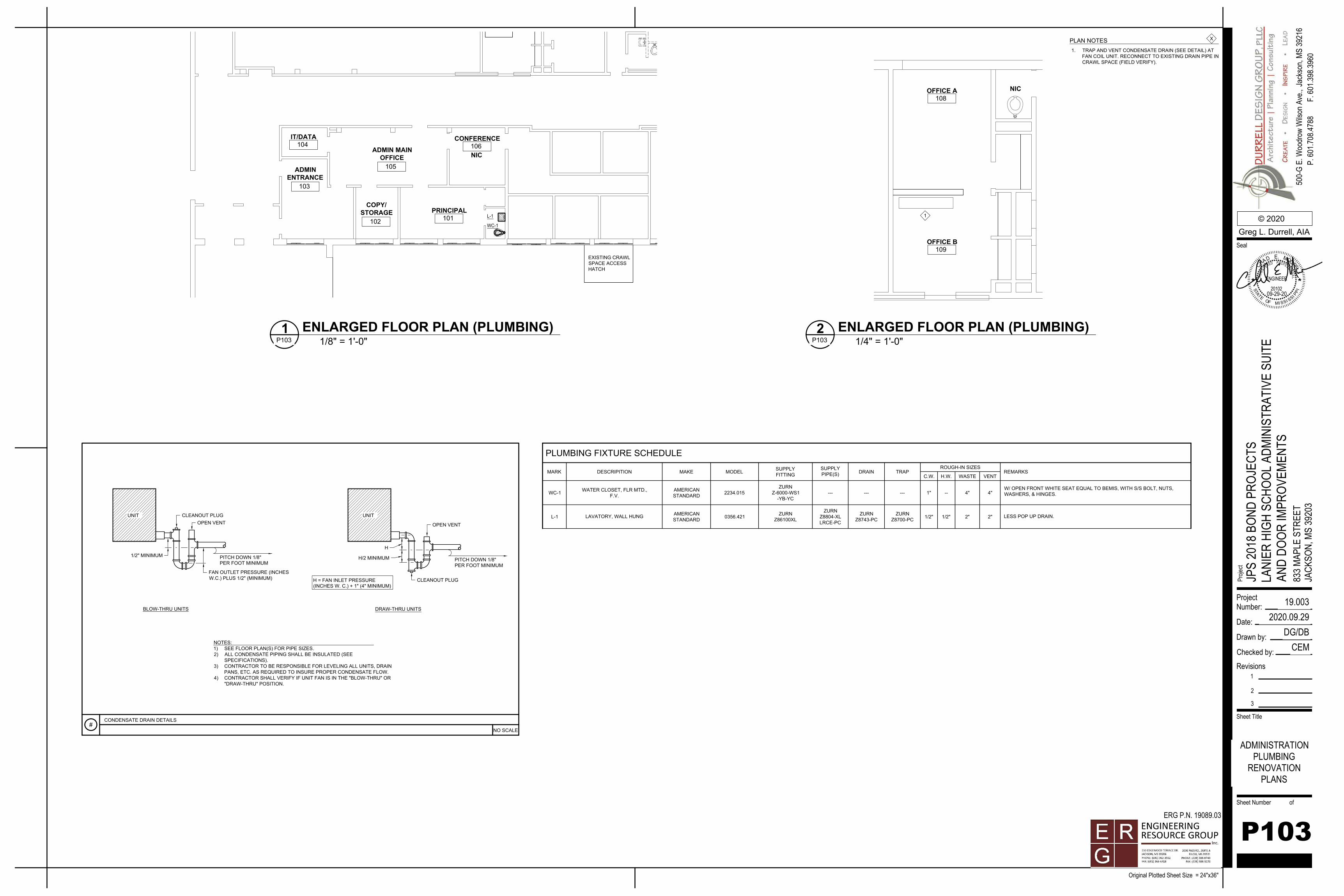
EXISTING CRAWLSPACE ACCESSHATCH
NIC
WC-1
L-1
ADMINENTRANCE
103
IT/DATA104
ADMIN MAINOFFICE
105
CONFERENCE106
PRINCIPAL101
COPY/STORAGE
102
NIC
OFFICE B109
OFFICE A108
1
MARK DESCRIPITION SUPPLYFITTINGMAKE MODEL
SUPPLYPIPE(S) DRAIN TRAP
PLUMBING FIXTURE SCHEDULE
C.W.
ROUGH-IN SIZES
H.W. WASTE VENTREMARKS
L-1 LAVATORY, WALL HUNG AMERICANSTANDARD 0356.421 ZURN
Z86100XL
ZURNZ8804-XLLRCE-PC
ZURNZ8743-PC
ZURNZ8700-PC 1/2" 1/2" 2" 2" LESS POP UP DRAIN.
WC-1 WATER CLOSET, FLR MTD.,F.V. 2234.015
ZURNZ-6000-WS1
-YB-YC--- --- --- 1" -- 4" 4"
W/ OPEN FRONT WHITE SEAT EQUAL TO BEMIS, WITH S/S BOLT, NUTS,WASHERS, & HINGES.
AMERICANSTANDARD
PLAN NOTES 1. TRAP AND VENT CONDENSATE DRAIN (SEE DETAIL) AT
FAN COIL UNIT. RECONNECT TO EXISTING DRAIN PIPE INCRAWL SPACE (FIELD VERIFY).
X
#CONDENSATE DRAIN DETAILS
UNIT
BLOW-THRU UNITS
UNIT
1/2" MINIMUM
CLEANOUT PLUGOPEN VENT
FAN OUTLET PRESSURE (INCHESW.C.) PLUS 1/2" (MINIMUM)
H
H/2 MINIMUM
CLEANOUT PLUG
OPEN VENT
PITCH DOWN 1/8"PER FOOT MINIMUM
PITCH DOWN 1/8"PER FOOT MINIMUM
H = FAN INLET PRESSURE(INCHES W. C.) + 1" (4" MINIMUM)
DRAW-THRU UNITS
NOTES:1) SEE FLOOR PLAN(S) FOR PIPE SIZES.2) ALL CONDENSATE PIPING SHALL BE INSULATED (SEE
SPECIFICATIONS).3) CONTRACTOR TO BE RESPONSIBLE FOR LEVELING ALL UNITS, DRAIN
PANS, ETC. AS REQUIRED TO INSURE PROPER CONDENSATE FLOW.4) CONTRACTOR SHALL VERIFY IF UNIT FAN IS IN THE "BLOW-THRU" OR
"DRAW-THRU" POSITION.
NO SCALE
ProjectNumber:
Date:
Drawn by:
Checked by:
Sheet Number of
Sheet Title
Proje
ct
Original Plotted Sheet Size = 24"x36"
© 2020
500-
G E.
Woo
drow
Wils
on A
ve.,
Seal
Jack
son,
MS 39
216
P. 60
1.708
.4788
F. 60
1.398
.3960
Revisions1
2
3
19.0032020.09.29
DG/DBCEM
JPS
2018
BON
D PR
OJEC
TSLA
NIER
HIG
H SC
HOOL
ADM
INIS
TRAT
IVE
SUIT
EAN
D DO
OR IM
PROV
EMEN
TS83
3 MAP
LE S
TREE
TJA
CKSO
N, M
S 39
203
ERG P.N. 19089.03
R
P
ETS
AT
SSIMOF I SS
20102
L
I PI
E
D
EGIS
T
A
CHME.
O
ENGINEER
P RRED
SIONA
FES ER
OO
09-29-20
P103
ADMINISTRATIONPLUMBING
RENOVATIONPLANS
1/8" = 1'-0"P1031 ENLARGED FLOOR PLAN (PLUMBING)
1/4" = 1'-0"P1032 ENLARGED FLOOR PLAN (PLUMBING)
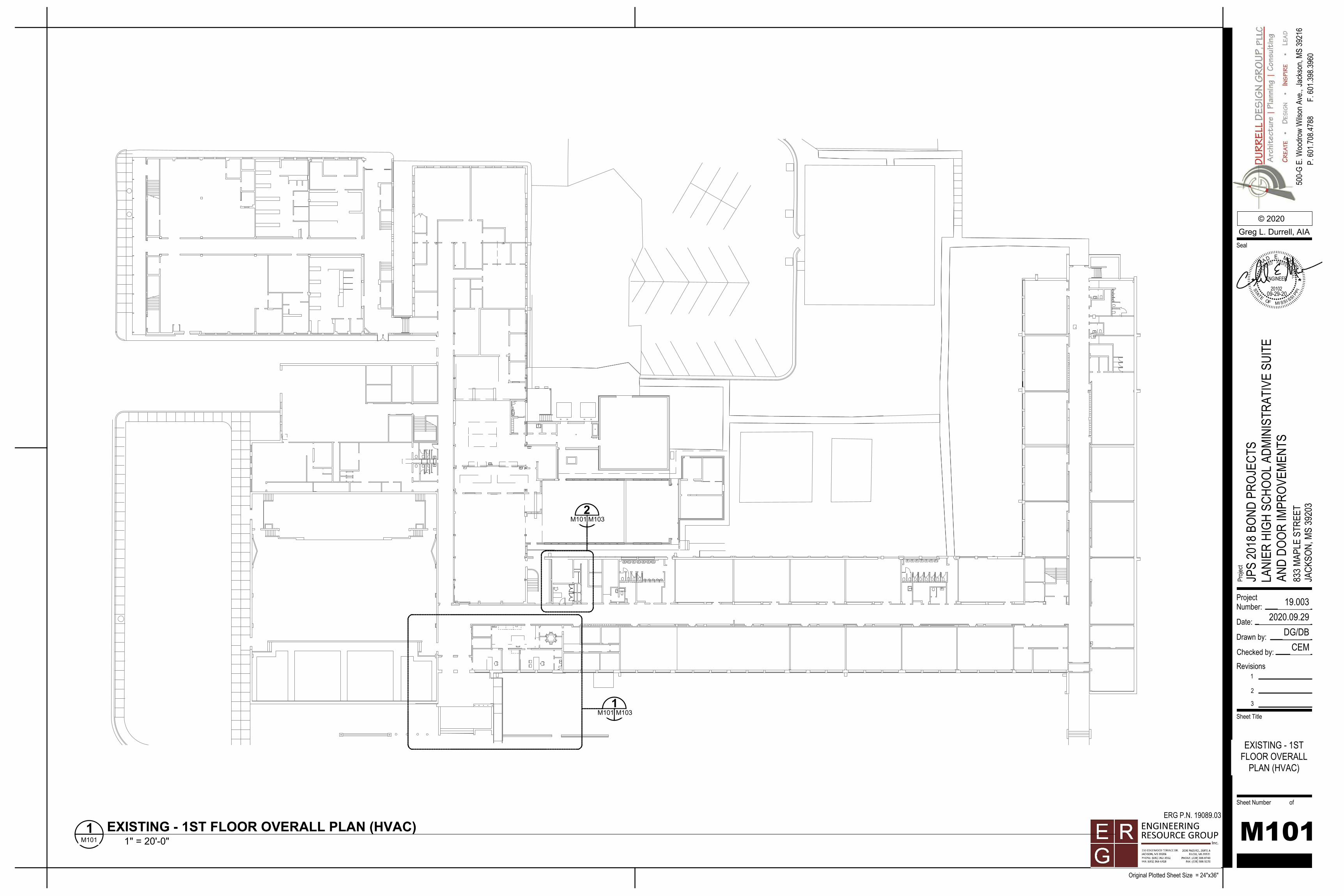
1M101 M103
2M101 M103
ProjectNumber:
Date:
Drawn by:
Checked by:
Sheet Number of
Sheet Title
Proje
ct
Original Plotted Sheet Size = 24"x36"
© 2020
500-
G E.
Woo
drow
Wils
on A
ve.,
Seal
Jack
son,
MS 39
216
P. 60
1.708
.4788
F. 60
1.398
.3960
Revisions1
2
3
19.0032020.09.29
DG/DBCEM
JPS
2018
BON
D PR
OJEC
TSLA
NIER
HIG
H SC
HOOL
ADM
INIS
TRAT
IVE
SUIT
EAN
D DO
OR IM
PROV
EMEN
TS83
3 MAP
LE S
TREE
TJA
CKSO
N, M
S 39
203
ERG P.N. 19089.03
R
P
ETS
AT
SSIMOF I SS
20102
L
I PI
E
D
EGIS
T
A
CHME.
O
ENGINEER
P RRED
SIONA
FES ER
OO
09-29-20
M101
EXISTING - 1STFLOOR OVERALL
PLAN (HVAC)
1" = 20'-0"M1011 EXISTING - 1ST FLOOR OVERALL PLAN (HVAC)
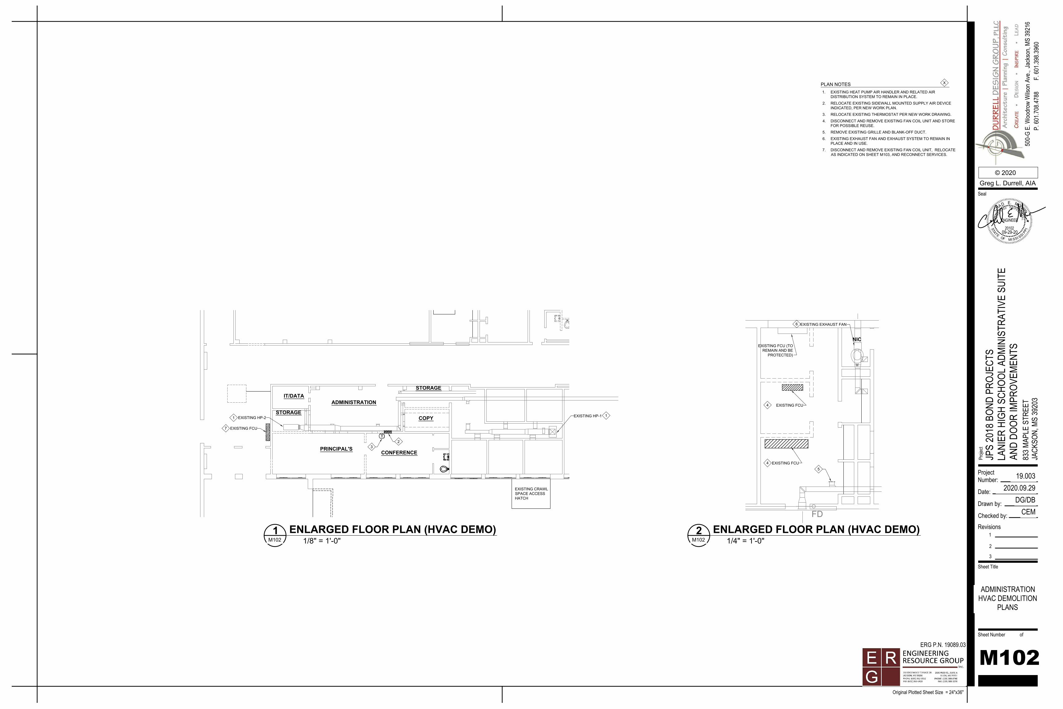
EXISTING CRAWLSPACE ACCESSHATCH
TT
IT/DATA
STORAGECOPY
STORAGE
PRINCIPAL'S
ADMINISTRATION
CONFERENCE
1EXISTING HP-2 EXISTING HP-1
3
1
2
7 EXISTING FCU
NIC
FD
EXISTING FCU (TOREMAIN AND BE
PROTECTED)
EXISTING FCU
EXISTING FCU
EXISTING EXHAUST FAN
4
45
6
PLAN NOTES 1. EXISTING HEAT PUMP AIR HANDLER AND RELATED AIR
DISTRIBUTION SYSTEM TO REMAIN IN PLACE.
2. RELOCATE EXISTING SIDEWALL MOUNTED SUPPLY AIR DEVICEINDICATED, PER NEW WORK PLAN.
3. RELOCATE EXISTING THERMOSTAT PER NEW WORK DRAWING.
4. DISCONNECT AND REMOVE EXISTING FAN COIL UNIT AND STOREFOR POSSIBLE REUSE.
5. REMOVE EXISTING GRILLE AND BLANK-OFF DUCT.
6. EXISTING EXHAUST FAN AND EXHAUST SYSTEM TO REMAIN INPLACE AND IN USE.
7. DISCONNECT AND REMOVE EXISTING FAN COIL UNIT, RELOCATEAS INDICATED ON SHEET M103, AND RECONNECT SERVICES.
X
ProjectNumber:
Date:
Drawn by:
Checked by:
Sheet Number of
Sheet Title
Proje
ct
Original Plotted Sheet Size = 24"x36"
© 2020
500-
G E.
Woo
drow
Wils
on A
ve.,
Seal
Jack
son,
MS 39
216
P. 60
1.708
.4788
F. 60
1.398
.3960
Revisions1
2
3
19.0032020.09.29
DG/DBCEM
JPS
2018
BON
D PR
OJEC
TSLA
NIER
HIG
H SC
HOOL
ADM
INIS
TRAT
IVE
SUIT
EAN
D DO
OR IM
PROV
EMEN
TS83
3 MAP
LE S
TREE
TJA
CKSO
N, M
S 39
203
ERG P.N. 19089.03
R
P
ET
SAT
SSIMOF I SS
20102
L
I PI
E
D
EGIS
T
A
CHME.
O
ENGINEER
P RRED
SIONA
FES ER
OO
09-29-20
M102
ADMINISTRATIONHVAC DEMOLITION
PLANS
1/8" = 1'-0"M1021 ENLARGED FLOOR PLAN (HVAC DEMO)
1/4" = 1'-0"M1022 ENLARGED FLOOR PLAN (HVAC DEMO)
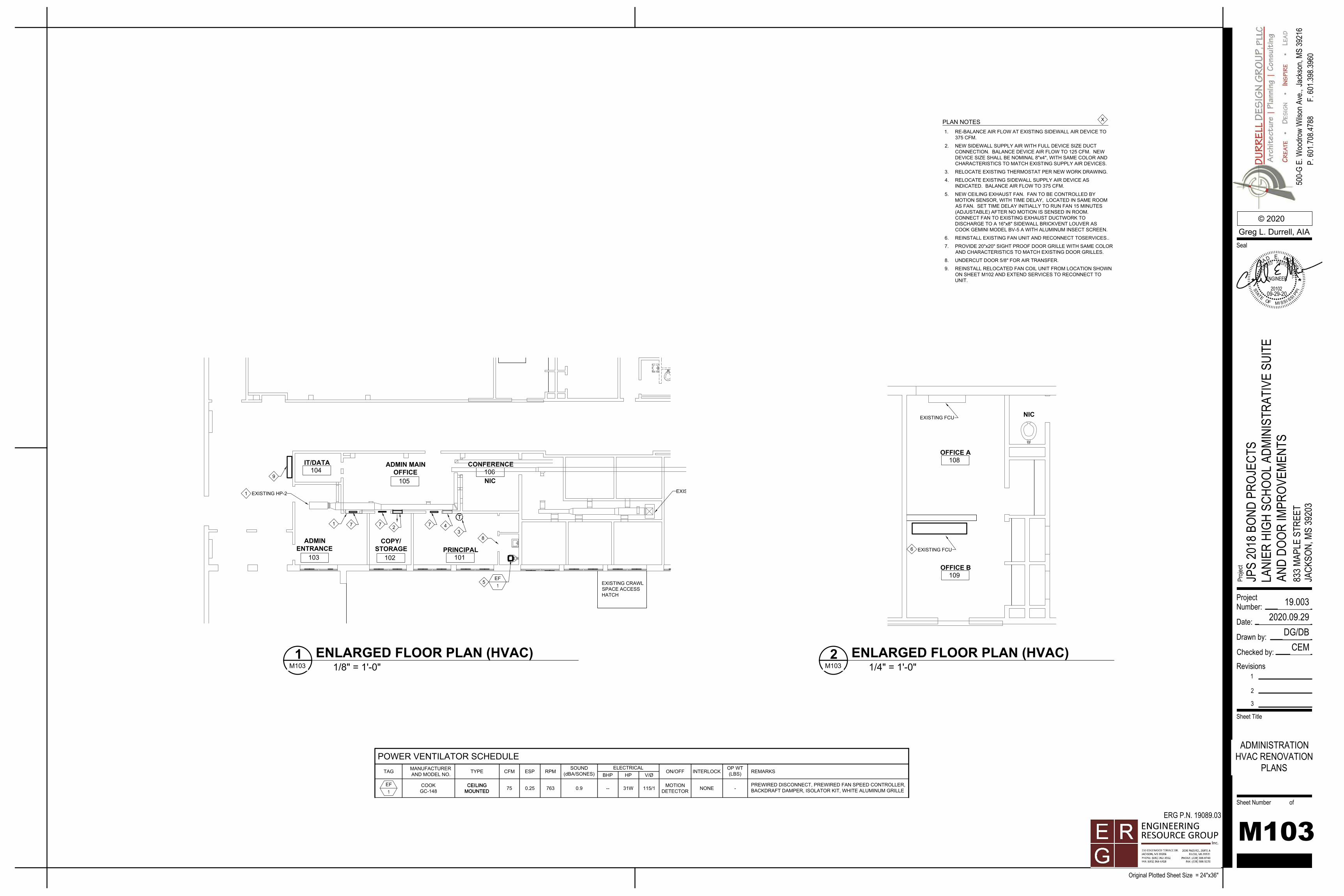
EXISTING CRAWLSPACE ACCESSHATCH
NIC
ADMINENTRANCE
103
IT/DATA104
ADMIN MAINOFFICE
105
CONFERENCE106
PRINCIPAL101
COPY/STORAGE
102
TT
EXISTING HP-2 EXISTING HP-1
13
1
EF1
5
2 4
8
777
9
NIC
OFFICE B109
OFFICE A108
EXISTING FCU
EXISTING FCU6
EF1
MANUFACTURERAND MODEL NO.TAG TYPE CFM ESP
SOUND(dBA/SONES) BHP HP V/Ø
RPMELECTRICAL OP WT
(LBS)ON/OFF INTERLOCK REMARKS
POWER VENTILATOR SCHEDULE
CEILINGMOUNTED -
PREWIRED DISCONNECT, PREWIRED FAN SPEED CONTROLLER,BACKDRAFT DAMPER, ISOLATOR KIT, WHITE ALUMINUM GRILLE
MOTIONDETECTOR NONECOOK
GC-148 75 0.25 -- 31W 115/1763 0.9CEILINGMOUNTED
PLAN NOTES 1. RE-BALANCE AIR FLOW AT EXISTING SIDEWALL AIR DEVICE TO
375 CFM.
2. NEW SIDEWALL SUPPLY AIR WITH FULL DEVICE SIZE DUCTCONNECTION. BALANCE DEVICE AIR FLOW TO 125 CFM. NEWDEVICE SIZE SHALL BE NOMINAL 8"x4", WITH SAME COLOR ANDCHARACTERISTICS TO MATCH EXISTING SUPPLY AIR DEVICES.
3. RELOCATE EXISTING THERMOSTAT PER NEW WORK DRAWING.
4. RELOCATE EXISTING SIDEWALL SUPPLY AIR DEVICE ASINDICATED. BALANCE AIR FLOW TO 375 CFM.
5. NEW CEILING EXHAUST FAN. FAN TO BE CONTROLLED BYMOTION SENSOR, WITH TIME DELAY, LOCATED IN SAME ROOMAS FAN. SET TIME DELAY INITIALLY TO RUN FAN 15 MINUTES(ADJUSTABLE) AFTER NO MOTION IS SENSED IN ROOM.CONNECT FAN TO EXISTING EXHAUST DUCTWORK TODISCHARGE TO A 16"x8" SIDEWALL BRICKVENT LOUVER ASCOOK GEMINI MODEL BV-5 A WITH ALUMINUM INSECT SCREEN.
6. REINSTALL EXISTING FAN UNIT AND RECONNECT TOSERVICES..
7. PROVIDE 20"x20" SIGHT PROOF DOOR GRILLE WITH SAME COLORAND CHARACTERISTICS TO MATCH EXISTING DOOR GRILLES.
8. UNDERCUT DOOR 5/8" FOR AIR TRANSFER.
9. REINSTALL RELOCATED FAN COIL UNIT FROM LOCATION SHOWNON SHEET M102 AND EXTEND SERVICES TO RECONNECT TOUNIT.
X
ProjectNumber:
Date:
Drawn by:
Checked by:
Sheet Number of
Sheet Title
Proje
ct
Original Plotted Sheet Size = 24"x36"
© 2020
500-
G E.
Woo
drow
Wils
on A
ve.,
Seal
Jack
son,
MS 39
216
P. 60
1.708
.4788
F. 60
1.398
.3960
Revisions1
2
3
19.0032020.09.29
DG/DBCEM
JPS
2018
BON
D PR
OJEC
TSLA
NIER
HIG
H SC
HOOL
ADM
INIS
TRAT
IVE
SUIT
EAN
D DO
OR IM
PROV
EMEN
TS83
3 MAP
LE S
TREE
TJA
CKSO
N, M
S 39
203
ERG P.N. 19089.03
R
P
ETS
AT
SSIMOF I SS
20102
L
I PI
E
D
EGIS
T
A
CHME.
O
ENGINEER
P RRED
SIONA
FES ER
OO
09-29-20
M103
ADMINISTRATIONHVAC RENOVATION
PLANS
1/8" = 1'-0"M1031 ENLARGED FLOOR PLAN (HVAC)
1/4" = 1'-0"M1032 ENLARGED FLOOR PLAN (HVAC)