Embed Size (px)
Citation preview

JB1 for VAG EA888 Gen 3 engines
Install Guide
Last Updated: /201
Use subject to terms and conditions posted at http://www.burgertuning.com/terms.htm
THIS PART IS LEGAL FOR USE ONLY IN COMPETITION RACING VEHICLES AS DEFINED UNDER CALIFORNIA LAW, AND IS NOT LEGAL FOR USE IN ANY OTHER MOTOR VEHICLE. California law defines a "racing vehicle" as "a competition vehicle not used on public highways." (Calif. Health & Safety Code 39048) This part may only be used on competition racing vehicles operated exclusively on a closed course in conjunction with a sanctioned racing event. Competition-only motor vehicles may not be driven to a racing event on a public highway and must be transported on a trailer or other carrier. USE OF THIS PART IN ANY OTHER VEHICLE MAY SUBJECT YOU TO FINES AND PENALTIES FOR VIOLATION OF FEDERAL AND/OR STATE LAW, WILL
VOID YOUR WARRANTY FROM BURGER MOTORSPORTS INC, AND CAN VOIDYOUR VEHICLE'S WARRANTY. It is your responsibility to comply with all applicable
federal and state laws relating to use of this part, and Burger Motorsports INC herebydisclaims any liability resulting from the failure to use this part in compliance with all applicable federal and state laws.
1
Step 1: Disconnect battery or let the car go into sleep state
It is advisable to either disconnect the cars battery when doing the install or let the car go to sleep by opening the hood and letting the car stand for 5-10min. Working on the plugs whilst the ECU is still active will trigger faults that will be stored.
Step 2: Remove the engine cover
The engine cover is held in place by three rubber grommets, it is removed by simply lifting it
up. This will expose the 3 sensors that need to be intercepted at the top of the engine bay.
In the engine overview below the sensors are marked A, B and C. There are slight variances between cars relative to the car having the ROW Dual injection motor or the US Single. Pictured is the dual injection motor but the sensors are in the same locations regardless of type. Sensor D is not pictured since its at the bottom of the engine bay and its the final step in the instruction manual.
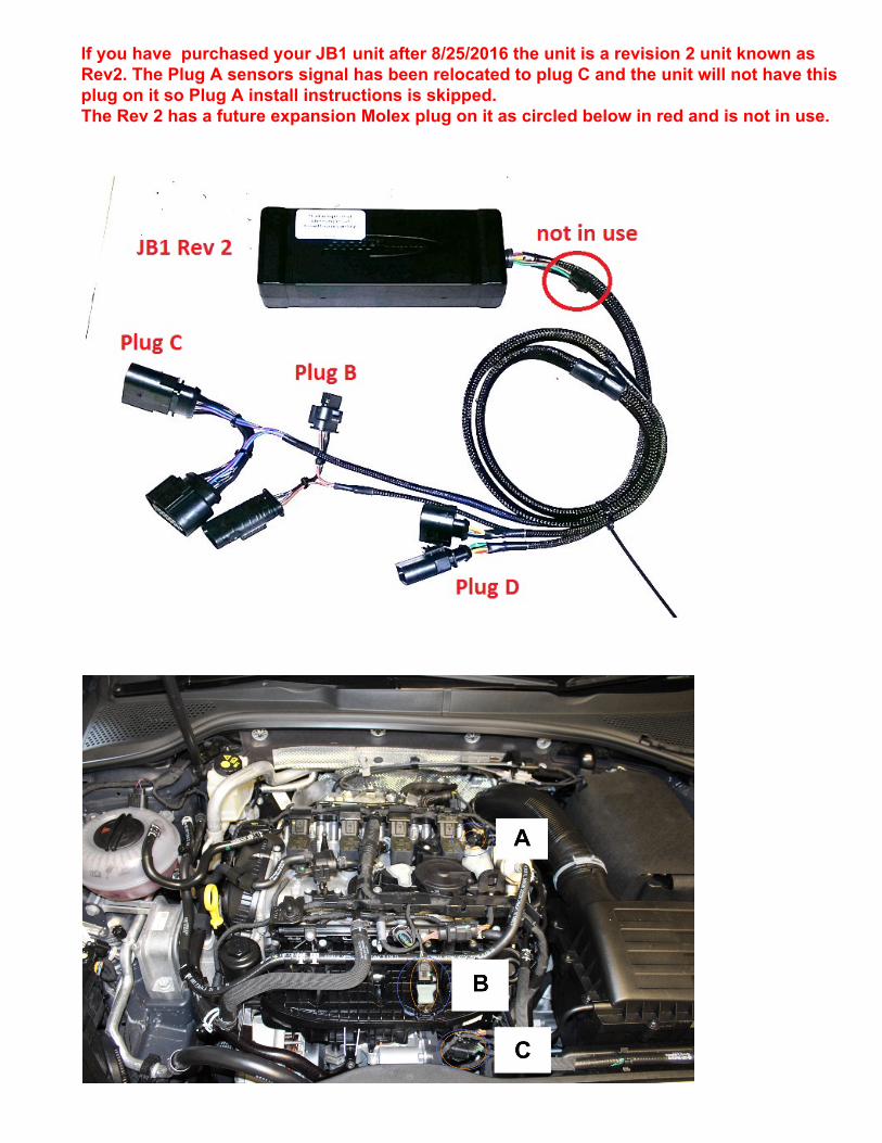
If you have purchased your JB1 unit after 8/25/2016 the unit is a revision 2 unit known as Rev2. The Plug A sensors signal has been relocated to plug C and the unit will not have this plug on it so Plug A install instructions is skipped.The Rev 2 has a future expansion Molex plug on it as circled below in red and is not in use.
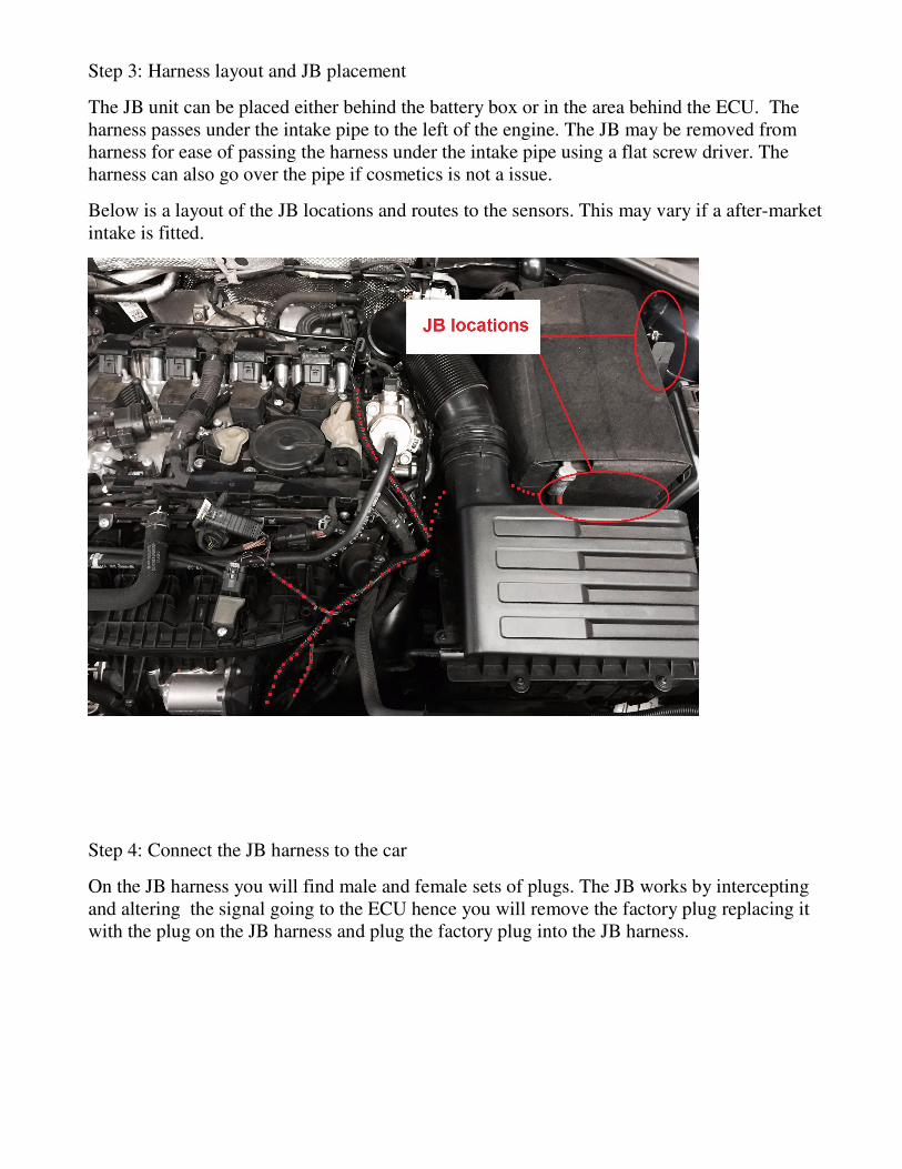
Step 3: Harness layout and JB placement
The JB unit can be placed either behind the battery box or in the area behind the ECU. The harness passes under the intake pipe to the left of the engine. The JB may be removed from harness for ease of passing the harness under the intake pipe using a flat screw driver. The harness can also go over the pipe if cosmetics is not a issue.
Below is a layout of the JB locations and routes to the sensors. This may vary if a after-market intake is fitted.
Step 4: Connect the JB harness to the car
On the JB harness you will find male and female sets of plugs. The JB works by intercepting and altering the signal going to the ECU hence you will remove the factory plug replacing it with the plug on the JB harness and plug the factory plug into the JB harness.
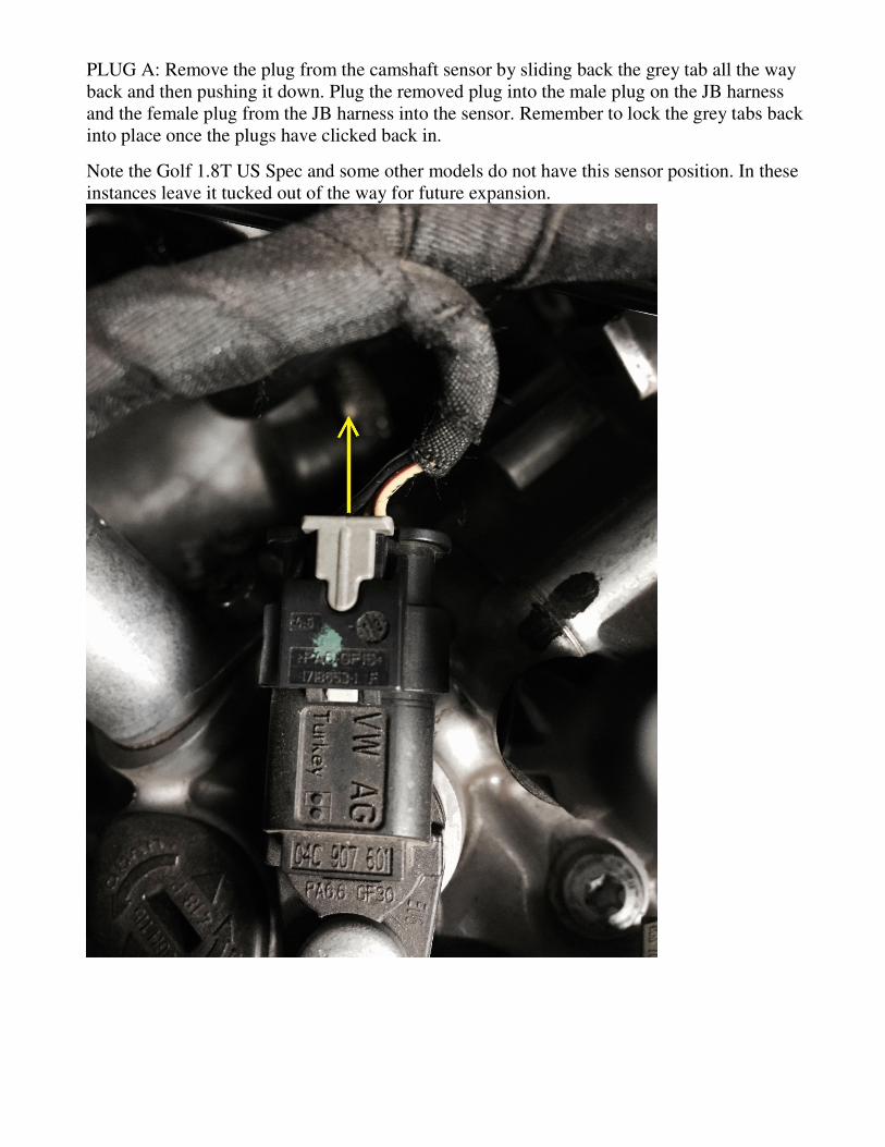
PLUG A: Remove the plug from the camshaft sensor by sliding back the grey tab all the way back and then pushing it down. Plug the removed plug into the male plug on the JB harness and the female plug from the JB harness into the sensor. Remember to lock the grey tabs back into place once the plugs have clicked back in.
Note the Golf 1.8T US Spec and some other models do not have this sensor position. In these instances leave it tucked out of the way for future expansion.
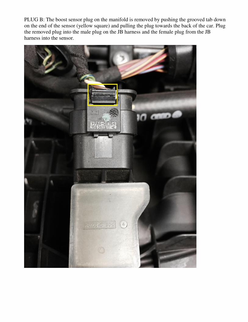
PLUG B: The boost sensor plug on the manifold is removed by pushing the grooved tab down on the end of the sensor (yellow square) and pulling the plug towards the back of the car. Plug the removed plug into the male plug on the JB harness and the female plug from the JB harness into the sensor.
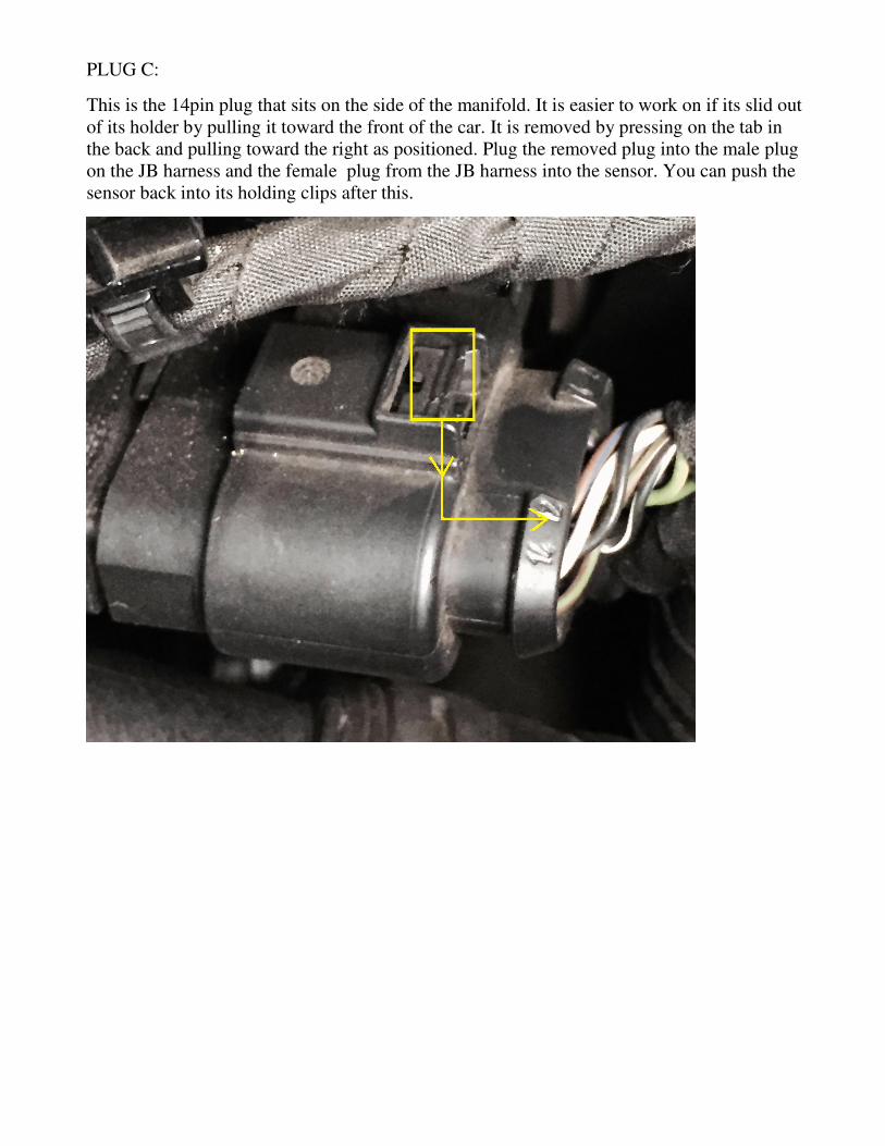
PLUG C:
This is the 14pin plug that sits on the side of the manifold. It is easier to work on if its slid out of its holder by pulling it toward the front of the car. It is removed by pressing on the tab in the back and pulling toward the right as positioned. Plug the removed plug into the male plug on the JB harness and the female plug from the JB harness into the sensor. You can push the sensor back into its holding clips after this.
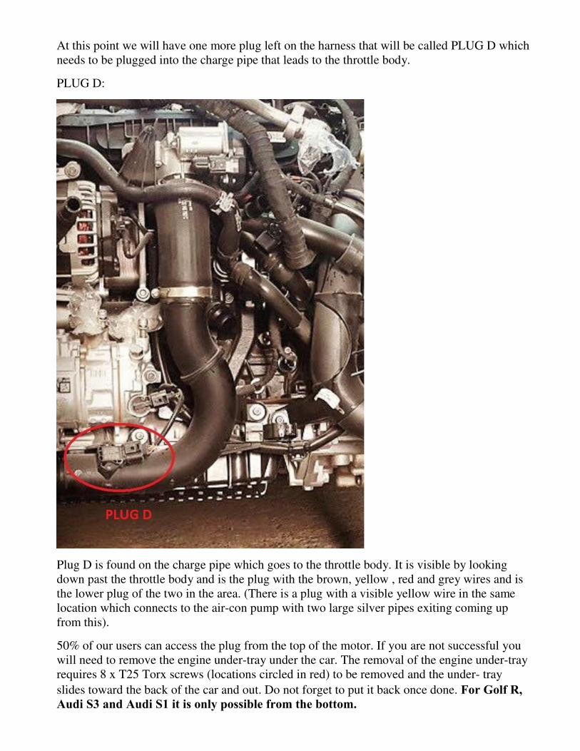
At this point we will have one more plug left on the harness that will be called PLUG D which needs to be plugged into the charge pipe that leads to the throttle body.
PLUG D:
Plug D is found on the charge pipe which goes to the throttle body. It is visible by looking down past the throttle body and is the plug with the brown, yellow , red and grey wires and is the lower plug of the two in the area. (There is a plug with a visible yellow wire in the same location which connects to the air-con pump with two large silver pipes exiting coming up from this).
50% of our users can access the plug from the top of the motor. If you are not successful you will need to remove the engine under-tray under the car. The removal of the engine under-tray requires 8 x T25 Torx screws (locations circled in red) to be removed and the under- tray
slides toward the back of the car and out. Do not forget to put it back once done. 1
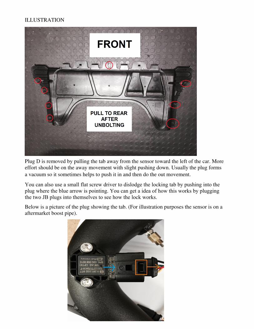
ILLUSTRATION
Plug D is removed by pulling the tab away from the sensor toward the left of the car. More effort should be on the away movement with slight pushing down. Usually the plug forms
a vacuum so it sometimes helps to push it in and then do the out movement.
..
Below is a picture of the plug showing the tab. (For illustration purposes the sensor is on a aftermarket boost pipe).
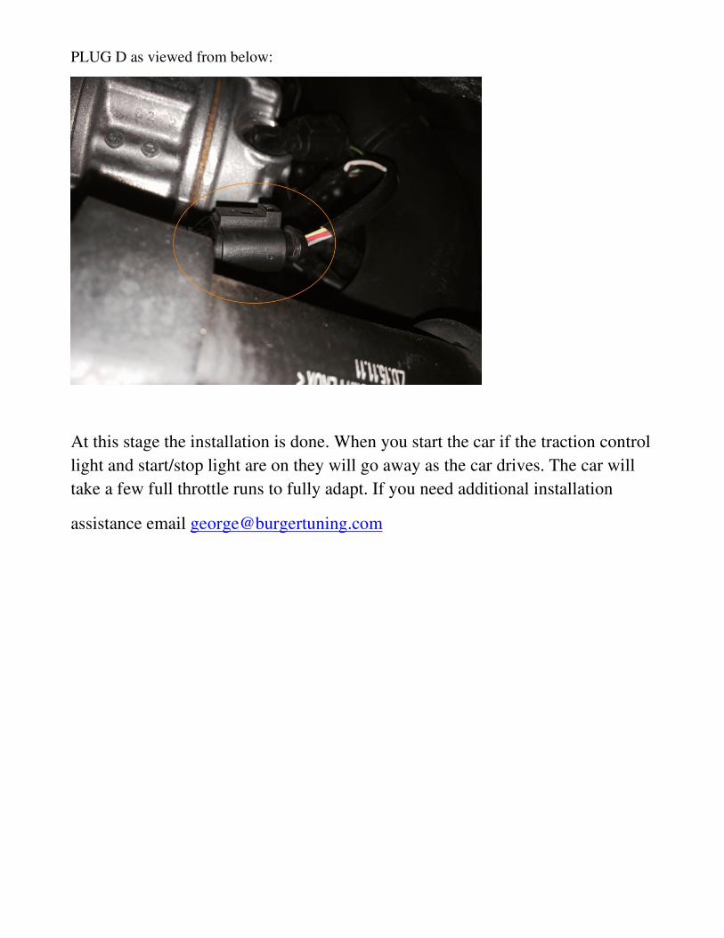
PLUG D as viewed from below:
At this stage the installation is done. When you start the car if the traction control
light and start/stop light are on they will go away as the car drives. The car will
take a few full throttle runs to fully adapt. If you need additional installation
assistance email [email protected]