Embed Size (px)
Citation preview
8/12/2019 Jbl manuel
http://slidepdf.com/reader/full/jbl-manuel 1/20
560GTi/660GTiCOMPETITION SPEAKER SYSTEMS
60TH ANNIVERSARY EDITION
OWNER’S GUIDE
8/12/2019 Jbl manuel
http://slidepdf.com/reader/full/jbl-manuel 2/20
FOR MORE THAN 60 YEARS, JBL ® HAS
DELIVERED PRODUCTS THAT EXEMPLIFY THE TECHNOLOGY
AND EXPERTISE GAINED THROUGH A LEADERSHIP ROLE IN
PROFESSIONAL SOUND REPRODUCTION. THE JBL NAME HAS
BEEN SYNONYMOUS WITH THE PRECISE, NATURALLY
ARTICULATED SOUND FOUND IN MANY OF THE WORLD’S MOST
PRESTIGIOUS LOCATIONS, INCLUDING CLUBS, CINEMAS AND
RECORDING STUDIOS, AND LIVE-MUSIC REINFORCEMENT IN
VENUES RANGING FROM CONCERT HALLS TO OUTDOOR
STADIUMS. JBL LOUDSPEAKERS ARE FOR THOSE WHO WON’T
COMPROMISE – IN THE STUDIO, AT HOME OR ON THE ROAD.
MORE THAN ANY OTHER COMPONENT, SPEAKERS DEFINE
THE SOUND OF AN AUDIO SYSTEM. THEY ARE THE CRITICAL
CHOICE THAT DETERMINES ULTIMATE PERFORMANCE. HOW
DOES A MARKET-LEADING BRAND LIKE JBL BUILD LOUD-
SPEAKERS THAT SATISFY SO MANY PEOPLE? WE USE THE
INDUSTRY’S MOST ADVANCED TESTING METHODS AND
EQUIPMENT, WITH A PANEL OF TRAINED LISTENERS TO
SCIENTIFICALLY QUANTIFY AND QUALIFY THE PERFORMANCE
OF EVERY JBL SPEAKER TO ENSURE THAT IT EXCEEDS EVEN
THE MOST DEMANDING EXPECTATIONS. THE INTRODUCTION
OF THE 560GTi AND 660GTi COMPETITION SPEAKER SYSTEMS
SETS YET A NEW STANDARD IN AUTOMOTIVE SOUND.
8/12/2019 Jbl manuel
http://slidepdf.com/reader/full/jbl-manuel 3/20
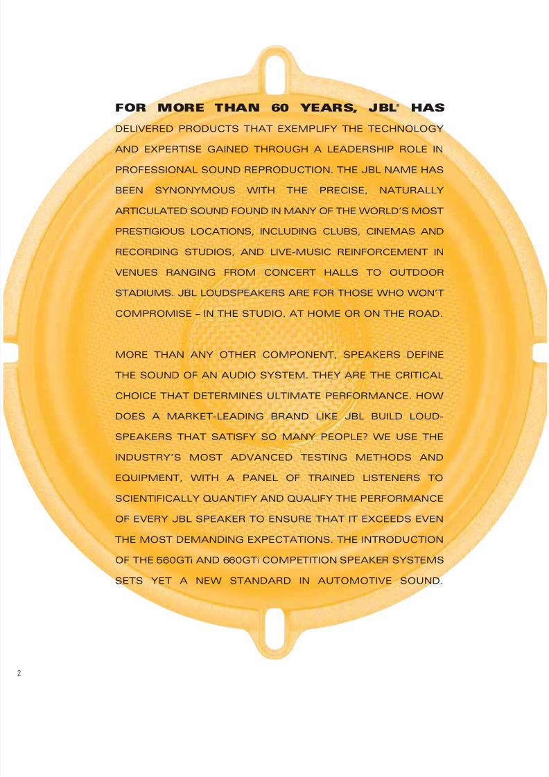
TABLE OF CONTENTS
INTRODUCTION ............................... .................2
SCIENCE OF JBL SPEAKER DESIGN ................4
PRODUCT FEATURES....................................... .6
SYSTEM DESIGN ............................. ...............10
SPECIFICATIONS ............................. ...............11
8/12/2019 Jbl manuel
http://slidepdf.com/reader/full/jbl-manuel 4/20
THERE ARE THREE STAGES IN ENGINEERINGLOUDSPEAKERS AT JBL:Computer-aided design and modeling, prototyping and testing. JBL speakers arethoroughly tested and qualified at each stage to ensure that the finished productperforms flawlessly.
Every speaker design starts with physical dimensions that facilitate installation infactory locations, along with a complete set of performance targets. Performancetargets include maximum SPL, or how loud the speaker must play at its limits.From the maximum SPL target, we determine the amount of power required todrive the speaker to its output limit and set a power-handling target. Sensitivity,another important performance target, indicates how efficiently the speaker con-verts electrical input into acoustic output. A frequency-response target is alsoincluded. This target describes not only the shape of the speaker’s response butalso the maximum allowable magnitude of narrow peaks and dips in its response.Finally, target Thiele/Small parameters are defined to describe the speaker’sbehavior at low-frequency cut-off in its intended application, whether that appli-
cation is a custom-built enclosure or the interior of a car’s door. A careful analysisof all these targets determines the excursion and heat dissipation required for thespeaker to produce the necessary frequency response at maximum SPL and maxi-mum input power. With that information, engineers design the motor, choosingvoice coil and magnet dimensions.
COMPUTER-AIDED DESIGN AND MODELINGDuring this phase of development, the engineers draw intricate diagrams of theproposed speaker’s construction. Once the computerized drawing is complete,it is imported into an analysis program. At JBL, we use extensive Finite ElementAnalysis (FEA) to model the performance of the speaker’s motor and moving parts.FEA divides the device being modeled into thousands of small parts or elements,and predicts performance based on the shape of the design and the materials thatwill be used in construction. The motor is analyzed using magnetic and thermalFEA. This analysis helps to ensure magnetic-field symmetry for low distortion,proper motor force required to drive the speaker’s moving assembly, and the heatdissipation needed for high power handling. The moving assembly – composed ofthe cone, voice coil and former, spider and surround – is analyzed using structuralFEA, which enables the engineers to observe the movement of the assembly toguarantee symmetry for low distortion. This analysis also permits the engineers todetermine the proper elasticity of the spider and surround to provide the appropriaterestoring force and perfect performance at the speaker’s excursion limits.
PROTOTYPINGOnce the computer-modeling phase is complete, technicians hand-build proto-types, machining metal parts and attaching them to prototype frames which arebuilt using a stereo lithography machine. The stereo lithography, or SLA, machine
uses a computer-guided laser to form a speaker basket out of a bath of plasticresin. Once the basket fit and finish are perfected, off-tool parts are built and thenfully working, production-grade samples are assembled.
AT JBL, SPEAKER DESIGN IS ALL SCIENCE.
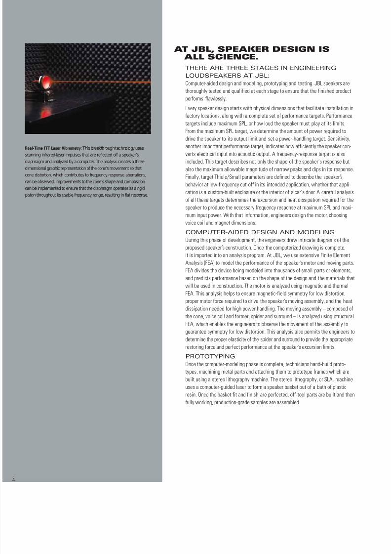
Real-Time FFT Laser Vibrometry: This breakthrough technology usesscanning infrared-laser impulses that are reflected off a speaker’sdiaphragm and analyzed by a computer. The analysis creates a three-dimensional graphic representation of the cone’s movement so thatcone distortion, which contributes to frequency-response aberrations,can be observed. Improvements to the cone’s shape and compositioncan be implemented to ensure that the diaphragm operates as a rigidpiston throughout its usable frequency range, resulting in flat response.
8/12/2019 Jbl manuel
http://slidepdf.com/reader/full/jbl-manuel 5/20
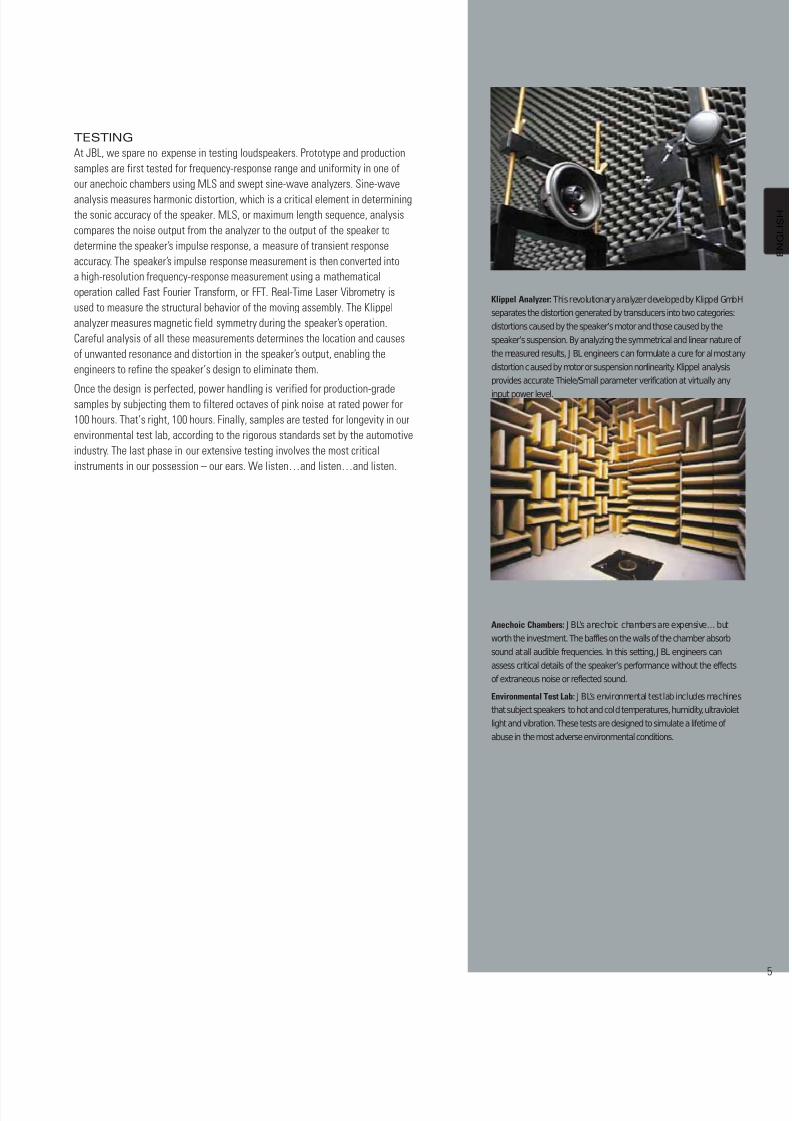
Anechoic Chambers: J BL’s anechoic chambers are expensive… butworth the investment. The baffles on the walls of the chamber absorbsound at all audible frequencies. In this setting, J BL engineers canassess critical details of the speaker’s performance without the effectsof extraneous noise or reflected sound.
Environmental Test Lab: J BL’s environmental test lab includes machinesthat subject speakers to hot and cold temperatures, humidity, ultravioletlight and vibration. These tests are designed to simulate a lifetime of abuse in the most adverse environmental conditions.
TESTINGAt JBL, we spare no expense in testing loudspeakers. Prototype and productionsamples are first tested for frequency-response range and uniformity in one ofour anechoic chambers using MLS and swept sine-wave analyzers. Sine-waveanalysis measures harmonic distortion, which is a critical element in determiningthe sonic accuracy of the speaker. MLS, or maximum length sequence, analysiscompares the noise output from the analyzer to the output of the speaker todetermine the speaker’s impulse response, a measure of transient responseaccuracy. The speaker’s impulse response measurement is then converted intoa high-resolution frequency-response measurement using a mathematicaloperation called Fast Fourier Transform, or FFT. Real-Time Laser Vibrometry isused to measure the structural behavior of the moving assembly. The Klippelanalyzer measures magnetic field symmetry during the speaker’s operation.Careful analysis of all these measurements determines the location and causesof unwanted resonance and distortion in the speaker’s output, enabling theengineers to refine the speaker’s design to eliminate them.
Once the design is perfected, power handling is verified for production-gradesamples by subjecting them to filtered octaves of pink noise at rated power for100 hours. That’s right, 100 hours. Finally, samples are tested for longevity in ourenvironmental test lab, according to the rigorous standards set by the automotiveindustry. The last phase in our extensive testing involves the most criticalinstruments in our possession – our ears. We listen…and listen…and listen.
Klippel Analyzer: This revolutionary analyzer developed by Klippel GmbHseparates the distortion generated by transducers into two categories:distortions caused by the speaker’s motor and those caused by thespeaker’s suspension. By analyzing the symmetrical and linear nature of the measured results, J BL engineers can formulate a cure for almost anydistortion caused by motor or suspension nonlinearity. Klippel analysisprovides accurate Thiele/Small parameter verification at virtually any
input power level.
8/12/2019 Jbl manuel
http://slidepdf.com/reader/full/jbl-manuel 6/20
GTi COMPETITION SPEAKERSYSTEM TECHNOLOGY:
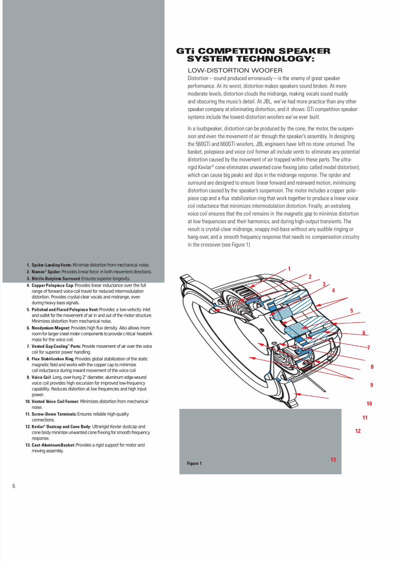
1. Spider-Landing Vents: Minimize distortion from mechanical noise.2. Nomex® Spider: Provides linear force in both movement directions.3. Nitrile-Butylene Surround: Ensures superior longevity.4. Copper Polepiece Cap: Provides linear inductance over the full
range of forward voice-coil travel for reduced intermodulationdistortion. Provides crystal-clear vocals and midrange, evenduring heavy bass signals.
5. Polished and Flared Polepiece Vent: Provides a low-velocity inletand outlet for the movement of air in and out of the motor structure.Minimizes distortion from mechanical noise.
6. Neodymium Magnet: Provides high flux density. Also allows moreroom for larger steel motor components to provide critical heatsinkmass for the voice coil.
7. Vented Gap Cooling™ Ports: Provide movement of air over the voicecoil for superior power handling.
8. Flux Stabilization Ring: Provides global stabilization of the staticmagnetic field and works with the copper cap to minimizecoil inductance during inward movement of the voice coil.
9. Voice Coil: Long, over-hung 2" diameter, aluminum edge-woundvoice coil provides high excursion for improved low-frequencycapability. Reduces distortion at low frequencies and high inputpower.
10. Vented Voice Coil Former: Minimizes distortion from mechanicalnoise.
11. Screw-Down Terminals: Ensures reliable high-qualityconnections.
12. Kevlar® Dustcap and Cone Body: Ultrarigid Kevlar dustcap andcone body minimize unwanted cone flexing for smooth frequencyresponse.
13. Cast-Aluminum Basket: Provides a rigid support for motor andmoving assembly.
LOW-DISTORTION WOOFERDistortion – sound produced erroneously – is the enemy of great speakerperformance. At its worst, distortion makes speakers sound broken. At moremoderate levels, distortion clouds the midrange, making vocals sound muddyand obscuring the music’s detail. At JBL, we’ve had more practice than any otherspeaker company at eliminating distortion, and it shows. GTi competition speakersystems include the lowest-distortion woofers we’ve ever built.
In a loudspeaker, distortion can be produced by the cone, the motor, the suspen-sion and even the movement of air through the speaker’s assembly. In designingthe 560GTi and 660GTi woofers, JBL engineers have left no stone unturned. Thebasket, polepiece and voice coil former all include vents to eliminate any potentialdistortion caused by the movement of air trapped within these parts. The ultra-rigid Kevlar® cone eliminates unwanted cone flexing (also called modal distortion),which can cause big peaks and dips in the midrange response. The spider andsurround are designed to ensure linear forward and rearward motion, minimizingdistortion caused by the speaker’s suspension. The motor includes a copper pole-piece cap and a flux stabilization ring that work together to produce a linear voicecoil inductance that minimizes intermodulation distortion. Finally, an extralongvoice coil ensures that the coil remains in the magnetic gap to minimize distortionat low frequencies and their harmonics, and during high-output transients. Theresult is crystal-clear midrange, snappy mid-bass without any audible ringing orhang-over, and a smooth frequency response that needs no compensation circuitryin the crossover (see Figure 1).
Figure 1
12
34
5
6
7
8
9
10
11
12
13
8/12/2019 Jbl manuel
http://slidepdf.com/reader/full/jbl-manuel 7/20
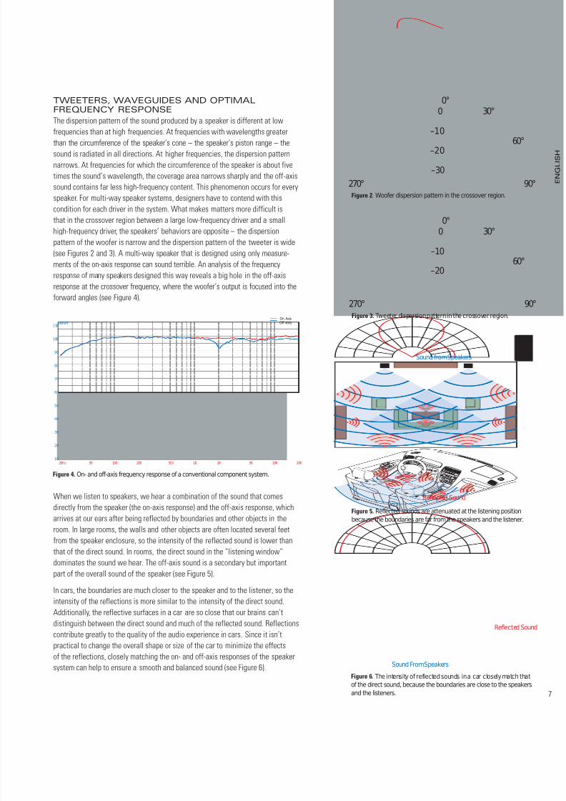
TWEETERS, WAVEGUIDES AND OPTIMALFREQUENCY RESPONSEThe dispersion pattern of the sound produced by a speaker is different at lowfrequencies than at high frequencies. At frequencies with wavelengths greaterthan the circumference of the speaker’s cone – the speaker’s piston range – thesound is radiated in all directions. At higher frequencies, the dispersion patternnarrows. At frequencies for which the circumference of the speaker is about fivetimes the sound’s wavelength, the coverage area narrows sharply and the off-axissound contains far less high-frequency content. This phenomenon occurs for everyspeaker. For multi-way speaker systems, designers have to contend with thiscondition for each driver in the system. What makes matters more difficult isthat in the crossover region between a large low-frequency driver and a smallhigh-frequency driver, the speakers’ behaviors are opposite – the dispersionpattern of the woofer is narrow and the dispersion pattern of the tweeter is wide(see Figures 2 and 3). A multi-way speaker that is designed using only measure-ments of the on-axis response can sound terrible. An analysis of the frequency
response of many speakers designed this way reveals a big hole in the off-axisresponse at the crossover frequency, where the woofer’s output is focused into theforward angles (see Figure 4).
When we listen to speakers, we hear a combination of the sound that comesdirectly from the speaker (the on-axis response) and the off-axis response, whicharrives at our ears after being reflected by boundaries and other objects in theroom. In large rooms, the walls and other objects are often located several feetfrom the speaker enclosure, so the intensity of the reflected sound is lower thanthat of the direct sound. In rooms, the direct sound in the “listening window”dominates the sound we hear. The off-axis sound is a secondary but importantpart of the overall sound of the speaker (see Figure 5).
In cars, the boundaries are much closer to the speaker and to the listener, so theintensity of the reflections is more similar to the intensity of the direct sound.Additionally, the reflective surfaces in a car are so close that our brains can’tdistinguish between the direct sound and much of the reflected sound. Reflectionscontribute greatly to the quality of the audio experience in cars. Since it isn’tpractical to change the overall shape or size of the car to minimize the effectsof the reflections, closely matching the on- and off-axis responses of the speakersystem can help to ensure a smooth and balanced sound (see Figure 6).
90°
60°
30°0°
270°
–20
–10
0
–30
Figure 2. Woofer dispersion pattern in the crossover region.
Figure 4. On- and off-axis frequency response of a conventional component system.
Figure 3. Tweeter dispersion pattern in the crossover region.
90
60°
30°0°
270°
–20
–10
0
Figure 5. Reflected sounds are attenuated at the listening positionbecause the boundaries are far from the speakers and the listener.
S ound f rom S peake rs
Reflec ted S ound
Figure 6. The intensity of reflected sounds in a car closely match thatof the direct sound, because the boundaries are close to the speakersand the listeners.
S ound F rom S peake rs
Reflec ted S oun
On Axis Off Axis
20Hz 50 100 200 500 1K 2K 5K 10K 20K
dBSPL
10
20
30
40
50
60
70
80
90
100
110
8/12/2019 Jbl manuel
http://slidepdf.com/reader/full/jbl-manuel 8/20
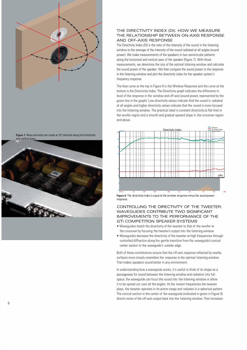
THE DIRECTIVITY INDEX (DI): HOW WE MEASURETHE RELATIONSHIP BETWEEN ON-AXIS RESPONSEAND OFF-AXIS RESPONSEThe Directivity Index (DI) is the ratio of the intensity of the sound in the listeningwindow to the average of the intensity of the sound radiated at all angles (soundpower). We make measurements of the speakers in two semicircular patterns
along the horizontal and vertical axes of the speaker (Figure 7). With thosemeasurements, we determine the size of the optimal listening window and calculatethe sound power of the speaker. We then compare the sound power to the responsein the listening window and plot the directivity index for the speaker system’sfrequency response.
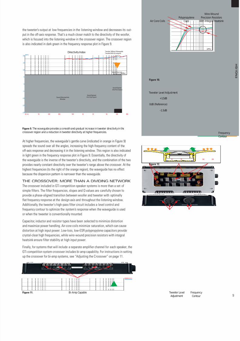
The blue curve at the top in Figure 8 is the Window Response and the curve at thebottom is the Directivity Index. The Directivity graph indicates the difference inlevel of the response in the window and off-axis (sound power, represented by thegreen line in the graph). Low-directivity values indicate that the sound is radiatedat all angles and higher directivity values indicate that the sound is more focusedinto the listening window. The practical ideal is constant directivity (a flat line) inthe woofer region and a smooth and gradual upward slope in the crossover regionand above.
CONTROLLING THE DIRECTIVITY OF THE TWEETER:WAVEGUIDES CONTRIBUTE TWO SIGNIFICANTIMPROVEMENTS TO THE PERFORMANCE OF THEGTi COMPETITION SPEAKER SYSTEMS• Waveguides match the directivity of the tweeter to that of the woofer at
the crossover by focusing the tweeter’s output into the listening window.• Waveguides decrease the directivity of the tweeter at high frequencies through
controlled diffraction along the gentle transition from the waveguide’s conicalcenter section to the waveguide’s outside edge.
Both of these contributions ensure that the off-axis response reflected by nearbysurfaces more closely resembles the response in the optimal listening window.That makes speakers sound better in any environment.
In understanding how a waveguide works, it’s useful to think of its shape as apassageway for sound between the listening window and radiation into fullspace; the waveguide can focus the sound into the listening window or allowit to be spread out over all the angles. At the lowest frequencies the tweeterplays, the tweeter operates in its piston range and radiates in a spherical pattern.The conical section in the center of the waveguide (indicated in green in Figure 9)directs some of the off-axis output back into the listening window. That increases
Figure 7. Measurements are made at 10° intervals along the horizontaland vertical axes.
Figure 8. The directivity index is equal to the window response minus the sound powerresponse.
Window Directivity Index Sound Power
20 Hz 50 100 200 500 1K 2K 5K 10K 20K
dBSPL
-10
0
10
20
90
100
80
70
Directivity Index
8/12/2019 Jbl manuel
http://slidepdf.com/reader/full/jbl-manuel 9/20
Figure 10.
Figure 12.
1K 2K 5K 10K 20K
the tweeter’s output at low frequencies in the listening window and decreases its out-put in the off-axis response. That’s a much closer match to the directivity of the woofer,which is focused into the listening window in the crossover region. The crossover regionis also indicated in dark green in the frequency response plot in Figure 9.
At higher frequencies, the waveguide’s gentle curve (indicated in orange in Figure 9)spreads the sound over all the angles, increasing the high-frequency content of theoff-axis response and decreasing it in the listening window. This region is also indicatedin light green in the frequency response plot in Figure 9. Essentially, the directivity ofthe waveguide is the inverse of the tweeter’s directivity, and the combination of the twoprovides nearly constant directivity over the tweeter’s range above the crossover. At thehighest frequencies (to the right of the orange region), the waveguide has no effectbecause the dispersion pattern is narrower than the waveguide.
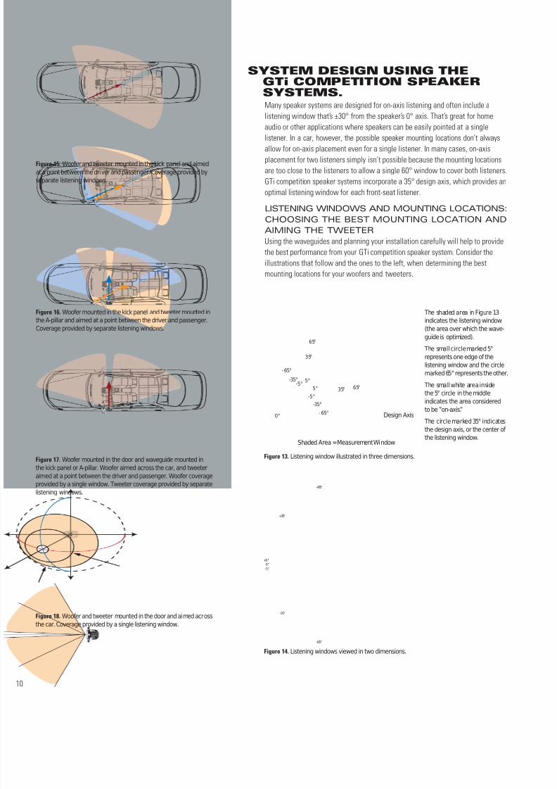
THE CROSSOVER: MORE THAN A DIVIDING NETWORKThe crossover included in GTi competition speaker systems is more than a set ofsimple filters. The filter frequencies, slopes and Q values are carefully chosen toprovide a phase-aligned transition between woofer and tweeter with optimallyflat frequency response at the design axis and throughout the listening window.Additionally, the tweeter’s high-pass filter circuit includes a level control andfrequency contour to optimize the system’s response when the waveguide is usedor when the tweeter is conventionally mounted.
Capacitor, inductor and resistor types have been selected to minimize distortionand maximize power handling. Air-core coils minimize saturation, which can causedistortion at high input power. Low-loss, low-ESR polypropylene capacitors providecrystal-clear high frequencies, while wire-wound precision resistors with integralheatsink ensure filter stability at high input power.
Finally, for systems that will include a separate amplifier channel for each speaker, theGTi competition system crossover includes bi-amp capability. For instructions in settingup the crossover for bi-amp systems, see “Adjusting the Crossover” on page 11.
Figure 9. The waveguide provides a smooth and gradual increase in tweeter directivity in thecrossover region and a reduction in tweeter directivity at higher frequencies.
20 Hz 50 100 200 500 1K 2K 5K 10K 20K
dBS PL
-20
-15
-10
-5
0
5
10
15
20
Direc tivity Index
Sound Di rec ted Into Window
Sound SpreadInto Free S pac e
S ound S preadInto Free S pac eS ound Di rec ted Into
Window
Tweete r Without Waveguide Tweete r With W aveguide
Figure 11. Bi-Amp Capable Tweeter LevelAdjustment
FrequencyContour
Air Core CoilsPolypropylene
Caps
Wire-WoundPrecision Resistors
With Integral Heatsink
FrequenContou
–1.5dB
0dB (Reference)
Tweeter Level Adjustment
+1.5dB
8/12/2019 Jbl manuel
http://slidepdf.com/reader/full/jbl-manuel 10/20
Many speaker systems are designed for on-axis listening and often include alistening window that’s ±30° from the speaker’s 0° axis. That’s great for homeaudio or other applications where speakers can be easily pointed at a single
listener. In a car, however, the possible speaker mounting locations don’t alwaysallow for on-axis placement even for a single listener. In many cases, on-axisplacement for two listeners simply isn’t possible because the mounting locationsare too close to the listeners to allow a single 60° window to cover both listeners.GTi competition speaker systems incorporate a 35° design axis, which provides anoptimal listening window for each front-seat listener.
LISTENING WINDOWS AND MOUNTING LOCATIONS:CHOOSING THE BEST MOUNTING LOCATION ANDAIMING THE TWEETERUsing the waveguides and planning your installation carefully will help to providethe best performance from your GTi competition speaker system. Consider theillustrations that follow and the ones to the left, when determining the best
mounting locations for your woofers and tweeters.
SYSTEM DESIGN USING THEGTi COMPETITION SPEAKERSYSTEMS.
Figure 13. Listening window illustrated in three dimensions.
The shaded area in Figure 13indicates the listening window(the area over which the wave-guide is optimized).
The small circle marked 5°represents one edge of thelistening window and the circlemarked 65°represents the other.
The small white area insidethe 5° circle in the middleindicates the area consideredto be ”on-axis. ”
The circle marked 35° indicatesthe design axis, or the center of the listening window.
65°
65°
- 65°
- 65°
35°
35°
-35°
-35° 5°5°
-5°
-5°
0°
S haded A rea =Measu rement Window
Design Axis
Figure 14. Listening windows viewed in two dimensions.
0°+5°
-5°
+35°
+65°
-65°
-35°
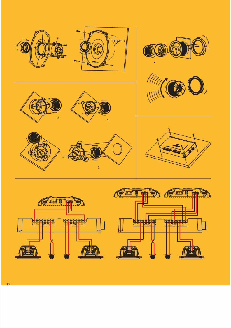
Figure 17. Woofer mounted in the door and waveguide mounted inthe kick panel or A-pillar. Woofer aimed across the car, and tweeteraimed at a point between the driver and passenger. Woofer coverageprovided by a single window. Tweeter coverage provided by separatelistening windows.
Figure 18. Woofer and tweeter mounted in the door and aimed acrossthe car. Coverage provided by a single listening window.
Figure 16. Woofer mounted in the kick panel and tweeter mounted inthe A-pillar and aimed at a point between the driver and passenger.Coverage provided by separate listening windows.
Figure 15. Woofer and tweeter mounted in the kick panel and aimedat a point between the driver and passenger. Coverage provided byseparate listening windows.
8/12/2019 Jbl manuel
http://slidepdf.com/reader/full/jbl-manuel 11/20
Figure 20.
Figure 19.
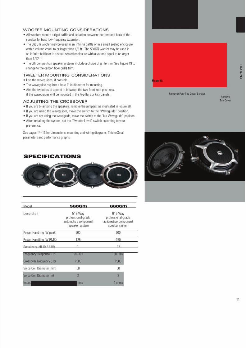
WOOFER MOUNTING CONSIDERATIONS
• All woofers require a rigid baffle and isolation between the front and back of thespeaker for best low-frequency extension.
• The 660GTi woofer may be used in an infinite baffle or in a small sealed enclosurewith a volume equal to or larger than 1/8 ft3. The 560GTi woofer may be used inan infinite baffle or in a small sealed enclosure with a volume equal to or largerthan 1/12 ft3.
• The GTi competition speaker systems include a choice of grille trim. See Figure 19 tochange to the carbon fiber grille trim.
TWEETER MOUNTING CONSIDERATIONS
• Use the waveguides, if possible.• The waveguide requires a hole 4" in diameter for mounting.• Aim the tweeters at a point in between the two front-seat positions,
if the waveguides will be mounted in the A-pillars or kick panels.
ADJUSTING THE CROSSOVER
• If you are bi-amping the speakers, remove the jumpers, as illustrated in Figure 20.• If you are using the waveguides, move the switch to the “Waveguide” position.• If you are not using the waveguide, move the switch to the “No Waveguide” position.
• After installing the system, set the “Tweeter Level” switch according to yourpreference.
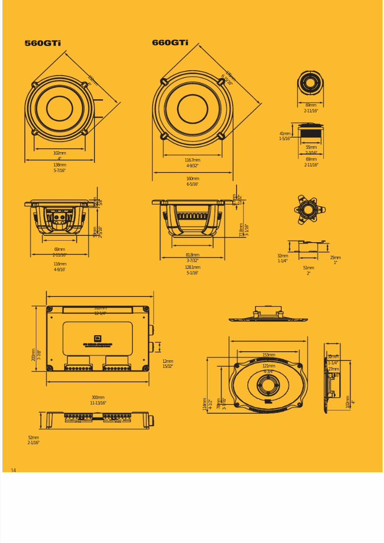
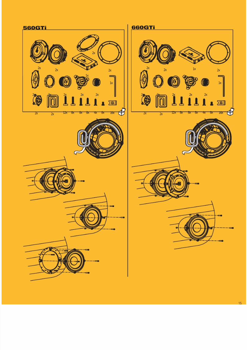
See pages 14–19 for dimensions, mounting and wiring diagrams, Thiele/Smallparameters and performance graphs.
Model 560GTi 660GTi
Description 5" 2-Way 6" 2-Wayprofessional-grade professional-grade
automotive component automotive componentspeaker system speaker system
Power Handling (W peak) 500 600
Power Handling (W RMS) 125 150
Sensitivity (dB @ 2.83V) 91 92
Frequency Response (Hz) 58–30k 50–30k
Crossover Frequency (Hz) 2500 2500
Voice Coil Diameter (mm) 50 50
Voice Coil Diameter (in) 2 2
Impedance 4 ohms 4 ohms
SPECIFICATIONS
RemoveTop Cover
Remover Four Top Cover Screws
Remove Jumpers
8/12/2019 Jbl manuel
http://slidepdf.com/reader/full/jbl-manuel 12/20
8/12/2019 Jbl manuel
http://slidepdf.com/reader/full/jbl-manuel 13/20
8/12/2019 Jbl manuel
http://slidepdf.com/reader/full/jbl-manuel 14/20
69mm2-11/16"
116mm4-9/16"
5 9 m m
2 - 5 / 1 6 "
1 6 m m
5 / 8 "
102mm4"
138mm5-7/16"
1 5 2 m m 6 "
81.8mm3-7/32"
128.1mm5-1/16"
7 7 . 8 m m
3 - 1 / 1 6 "
8 . 7 m m
1 1 / 3 2 "
116.7mm4-9/32"
160mm6-5/16"
1 7 6 m m 6 - 1 5 / 1 6 "
300mm11-13/16"
52mm2-1/16"
12mm15/32"
2 0 0 m m
7 - 7 / 8 "
312mm12-1/4"
55mm2-3/16"69mm
2-11/16"
41mm1-5/16"
69mm2-11/16"
32mm1-1/4"
51mm2"
25mm1"
121mm4-3/4"
153mm6"
1 1 4 m m
4 - 1 / 2 "
7 8 m m
3 - 1 / 1 6 "
32mm1-1/4"27mm1-1/16"
1 0 2 m m
4 "
560GTi 660GTi
8/12/2019 Jbl manuel
http://slidepdf.com/reader/full/jbl-manuel 15/20
560GTi 660GTi
2x 2x
1x
2x
2x 2x 2x 2x 2x
2x 2x 12x 8x 8x 4x 8x8x
1x
16x
2x2x 2x 1x
2x 2x 2x 2x 2x
2x 2x 12x 8x 8x 4x 8x8x
1x
16x
2x
8/12/2019 Jbl manuel
http://slidepdf.com/reader/full/jbl-manuel 16/20
12
3
1
2
4" (102mm)1
2
3
1
2
1
2
1
2
1
2

8/12/2019 Jbl manuel
http://slidepdf.com/reader/full/jbl-manuel 17/20
560GTi
8/12/2019 Jbl manuel
http://slidepdf.com/reader/full/jbl-manuel 18/20
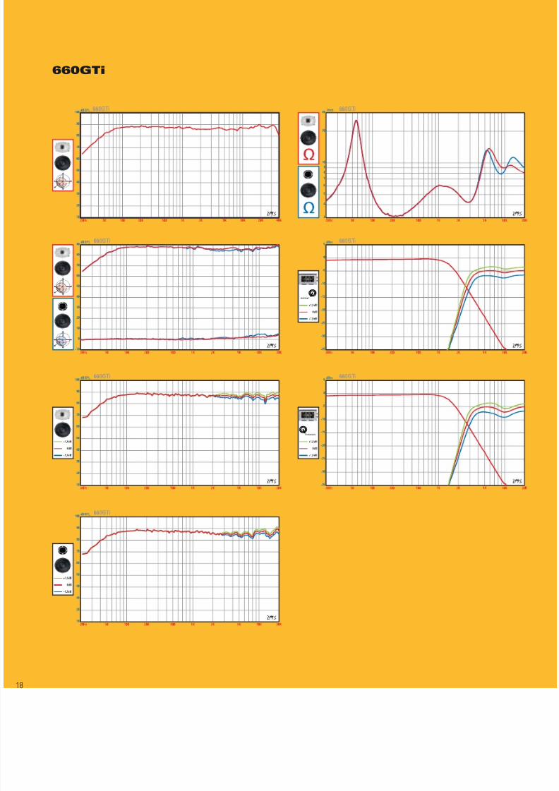
660GTi
8/12/2019 Jbl manuel
http://slidepdf.com/reader/full/jbl-manuel 19/20
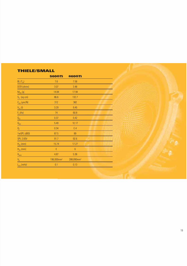
THIELE/SMALL560GTi 660GTi
BL (TM) 7.6 7.56
DCR (ohms) 3.07 3.48
MMS (g) 14.84 17.94SD (sq cm) 86.6 132.7
CMS (µm/N) 312 382
VAS (l) 3.29 9.45
FS (Hz) 74 60.8
QES 0.37 0.42
QMS 5.49 10.17
QT 0.34 0.4
1wSPL (dB0) 87.5 89
SPL 2.83V 91.7 92.6HVC(mm) 15.74 17.27
HAG (mm) 6 6
XMAX 4.87 5.36
VB 196,000mm3 288,890mm3
LEVC(mHz) 0.1 0.13
8/12/2019 Jbl manuel
http://slidepdf.com/reader/full/jbl-manuel 20/20
Harman Consumer Group, Inc.
250 Crossways Park Drive, Woodbury, NY 11797 USA
2, route de Tours, 72500, Château du Loir, France
516.496.3400 (USA only)www.jbl.com
THE OFFICIAL BRANDOF LIVE MUSIC.
©2007 Harman International Industries, Incorporated.All rights reserved.
Part No. 560/660GTiOM Printed 3/07
J BL is a trademark of Harman International Industries, Incorporated, registered in the United States and/or other countries.Vented Gap Cooling is a trademark of Harman International Industries, Incorporated.
Nomex and Kevlar are registered trademarks of E.I. du Pont de Nemours and Company.
Features, specifications and appearance are subject to change without notice.
Designed, edited and digitally produced by Harman Consumer Group Marketing & Design Center, Woodbury, NY, USA.