Embed Size (px)
Citation preview

Operational Decision Making Support -
JCDS- Architecture
Maxime Tardif (Thales), Gino Pelletier (Neosapiens), Guy Gosselin (Thales), Dominic Côté (Thales), Marco Savard (Neosapiens)
Prepared by:
Thales Canada, Land & Joint Systems Division 1405, boul. Du Parc-Technologique, 2nd Floor Québec, QC G1P 4P5
Contract number: W7701-054996/008/QCL Contract Scientific Authority: Micheline Bélanger, 418-844-4000 Ext. 4734Technical Authority: Normand Pageau, 418-844-4000 Ext. 4674
Defence R&D Canada – ValcartierContract Report
DRDC Valcartier CR 2009-118March 2009
The scientific or technical validity of this Contract Report is entirely the responsibility of the contractor and thecontents do not necessarily have the approval or endorsement of Defence R&D Canada.


Operational Decision Making Support - JCDS- Architecture Contract Number: W7701-054996/008/QCL
Prepared by
Thales Canada, Land & Joint Systems Division 1405, boul. Du Parc-Technologique, 2nd Floor
Québec, QC G1P 4P5
For
Recherche et Développement pour la Defense Canada/Defence Reseach and Development Canada (RDDC/DRDV)
2459, boul Pie XI Nord, Val-Bélair, QC G3J 1X5
Authors : Maxime Tardif (Thales) Scientist Authority : Micheline Bélanger (DRDC/RDDC)
Gino Pelletier (Neosapiens) Technical Authority : Normand Pageau (DRDC/RDDC)
Guy Gosselin (Thales)
Dominic Côté (Thales)
Marco Savard (Neosapiens)
© Her Majesty the Queen in Right of Canada, as represented by the Minister of National Defence, 2009
The scientific or technical validity of this Contract Report is entirely the responsibility of the Contractor and the contents do not necessarily have the approval or endorsement of Defence R&D Canada
Operational Decision Making Support - JCDS-COPlanS Architecture
Page 2
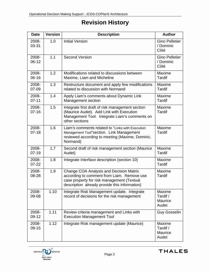
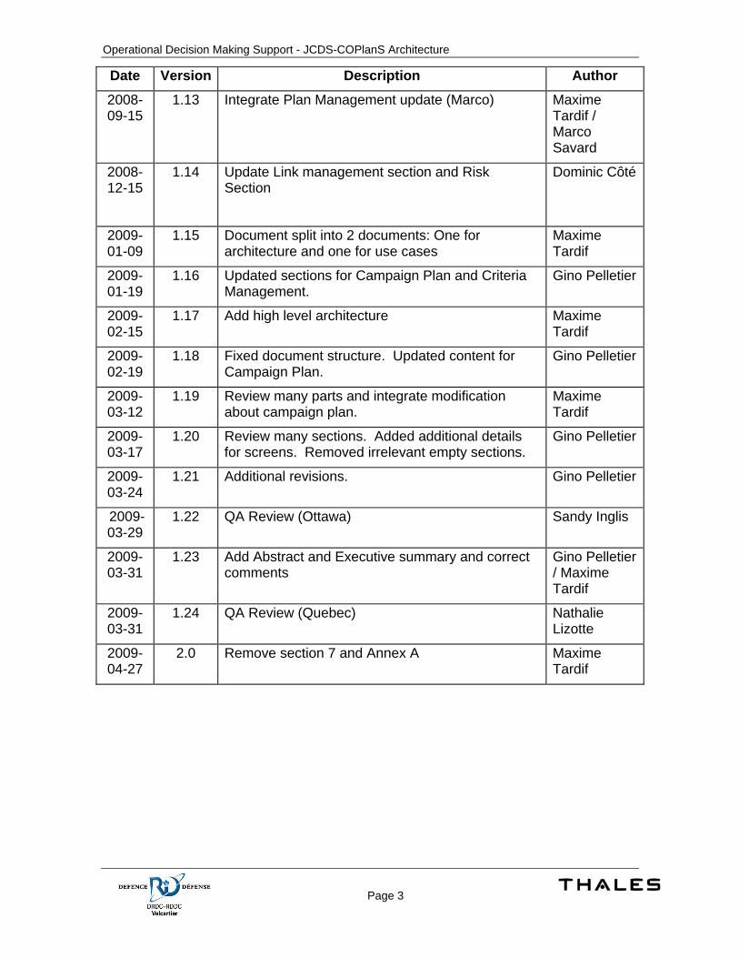
Revision History
Date Version Description Author
2008-03-31
1.0 Initial Version Gino Pelletier / Dominic Côté
2008-06-12
1.1 Second Version Gino Pelletier / Dominic Côté
2008-06-16
1.2 Modifications related to discussions between Maxime, Liam and Micheline
Maxime Tardif
2008-07-09
1.3 Restructure document and apply few modifications related to discussion with Normand
Maxime Tardif
2008-07-11
1.4 Apply Liam’s comments about Dynamic Link Management section
Maxime Tardif
2008-07-16
1.5 Integrate first draft of risk management section (Maurice Audet). Add Link with Execution Management Tool. Integrate Liam’s comments on other sections
Maxime Tardif
2008-07-18
1.6 Liam’s comments related to “Links with Execution Management Tool”section. Link Management reviewed according to meeting (Maxime, Dominic, Normand)
Maxime Tardif
2008-07-19
1.7 Second draft of risk management section (Maurice Audet)
Maxime Tardif
2008-07-22
1.8 Integrate Interface description (section 10) Maxime Tardif
2008-08-28
1.9 Change COA Analysis and Decision Matrix according to comment from Liam. Remove use case property for risk management (Textual description already provide this information)
Maxime Tardif
2008-09-08
1.10 Integrate Risk Management update. Integrate record of decisions for the risk management
Maxime Tardif / Maurice Audet
2008-09-12
1.11 Review criteria management and Links with Execution Management Tool
Guy Gosselin
2008-09-15
1.12 Integrate Risk management update (Maurice) Maxime Tardif / Maurice Audet
Operational Decision Making Support - JCDS-COPlanS Architecture
Page 3
Date Version Description Author
2008-09-15
1.13 Integrate Plan Management update (Marco) Maxime Tardif / Marco Savard
2008-12-15
1.14 Update Link management section and Risk Section
Dominic Côté
2009-01-09
1.15 Document split into 2 documents: One for architecture and one for use cases
Maxime Tardif
2009-01-19
1.16 Updated sections for Campaign Plan and Criteria Management.
Gino Pelletier
2009-02-15
1.17 Add high level architecture Maxime Tardif
2009-02-19
1.18 Fixed document structure. Updated content for Campaign Plan.
Gino Pelletier
2009-03-12
1.19 Review many parts and integrate modification about campaign plan.
Maxime Tardif
2009-03-17
1.20 Review many sections. Added additional details for screens. Removed irrelevant empty sections.
Gino Pelletier
2009-03-24
1.21 Additional revisions. Gino Pelletier
2009-03-29
1.22 QA Review (Ottawa) Sandy Inglis
2009-03-31
1.23 Add Abstract and Executive summary and correct comments
Gino Pelletier / Maxime Tardif
2009-03-31
1.24 QA Review (Quebec) Nathalie Lizotte
2009-04-27
2.0 Remove section 7 and Annex A Maxime Tardif
Operational Decision Making Support - JCDS-COPlanS Architecture
Page 4
ABSTRACT
Defence R&D Canada –Valcartier (DRDC Valcartier) centre initiated a research activity aimed at investigating and developing approaches and concepts to support operational decision-making within the context of the Canadian Forces Operational Planning Process (CFOPP). In an effort to develop a more effective adaptive planning process, this investigation focused on examining new structured approaches to enhance and facilitate courses of action (COA) analysis and selection. In particular, a review of possible approaches for the dynamic link management between CFOPP elements, for the COA evaluation criteria management, in an effects-based environment and for enhanced decision-matrixes, with associated concepts; was completed. A computer-based system called “Collaborative Operations Planning System (COPlanS)” was used as an experimental framework to demonstrate a possible operationalisation of these approaches. COPlanS has been developed at DRDC Valcartier to support the CFOPP. COPlanS is an integrated flexible suite of planning, decision-aid and workflow management tools aimed at supporting a distributed team involved in the planning of military operations.
This document details the design of the mock-ups’ implementation, their interfaces and the changes required in the COPlanS components to support the proposed functionalities.
RÉSUMÉ
Le Centre de Recherche & Développement pour la Défense Canada – Valcartier (CRDD Valcartier) a entrepris une activité de recherche visant le développement d’approches et de concepts pour améliorer l’aide au décideur dans le contexte du Processus de Planification Opérationnelle des Forces canadiennes (PPOFC). Dans le but de déveloper un processus de planification plus efficace et flexible ; cette étude vise à examiner plusieurs nouvelles approches structurées pour faciliter et améliorer l’analyse et la sélection des suites d’action (SAs). En particulier, une revue des approches possibles a été effectuée, sur l’analyse des liens possibles entre les éléments de planification du PPOFC, sur la gestion des critères d’évaluation pour les Sas (qui retirent des effets opérationels) et sur les matrices d’aide à la décision. Le système numérique automatisé appelé “Collaborative Operations Planning System (COPlanS)”, a servi en tant que base expérimentale, afin de démontrer l’opérationnalisation des approches possibles. COPlanS a été mis au point au CRDD Valcartier pour traiter le PPOFC. COPlanS intègre une série flexible de composantes de planification, d’aide à la décision et d’outils de gestion des processus métiers, visant la planification, en collaboration avec des membres d’équipes dispersées d’opérations militaires.
Ce document décrit la conception des prototypes et des interfaces utilisateurs, ainsi que les changements requis dans les différentes composantes de COPlanS pour supporter les fonctionnalités proposées.

Operational Decision Making Support - JCDS-COPlanS Architecture
Page 5
EXECUTIVE SUMMARY
One of the mission critical deficiencies identified by Canada COM (Canada Command) is performing effective adaptive planning. Effective adaptive planning might be seen as the ability to conduct a timely and flexible planning process and to develop options, for employing joint capabilities across the sea, air, land and cyber spectrums. The Canadian Forces Operational Planning Process (CFOPP) is the current structured way used by Canada COM to perform military planning and problem solving. A large portion of this process deals with brainstorming, holistic situation understanding and high level planning.
In order to enhance operational level planning and decision-making, at this level of command, DRDC Valcartier initiated this study, to investigate and develop new approaches and concepts, to support operational decision-making, within the context of the CFOPP. In an effort to develop a more effective adaptive planning process, this investigation focused on examining new structured approaches, to enhance and facilitate courses of action (COA) analysis and selection.
Solutions have been proposed and selected according to previous study (covered by the document ‘Operational Decision Making Support - Operational Concept Description). This document describes the design for Mock-up implementations, for these solutions.
COPlanS is an existing system, providing various components and services. The design for the new features conforms to these existing features and components. In many cases, new features extend existing features. The COPlanS’ class model and the underlying database required changes to support these features. Many classes are new. Some existing classes and components also required changes to support the new features.
COPlanS is an extensible tool and aim at easily integrate new concepts. The main goal for the implementation design of the link management feature is to minimize the requirement for new modifications and new code to support new concepts. Abstract concepts such as analysis element with the use of objects orientated concepts such as inheritance; ensure that new concepts can be added to the OPP analysis process, with a low cost, from a design and development point of view. It also ensures stability and uniformity between implementations for the different concepts.
The graphics features offered many challenges. The goals were to have support for advanced graphics manipulation and to leverage the services provided by COPlanS such as the database layer mechanisms for update notifications. It was also desired to hide the transaction level to the specific features implementation by providing mechanisms to manage objects that required persistence. In order to meet the first goal with the provided timeframe, an external library ‘JHotDraw’ was integrated in COPlanS. A lightweight library has been created on top of this graphics library to meet the second goal and to integrate the graphics features in the COPlanS’ framework.
The JCDS service uses the database layers to connect with the COPlanS’ server. This layer ensures that the data on the client is synchronized with the server regardless of the source of a change in the data. It provides notification mechanisms allowing the service to notify other JCDS components when some pre-defined changes occur. It also offers the transaction mechanisms to apply changes required by EMPA when the service receives requests.
The plan management features required support to copy plans. The design’s goal was to offer a generic copy mechanism to minimize the changes required if new concepts were added to COPlanS. The copy mechanism should also offer the possibility to dynamically customize the copy process. Another goal was to ensure that it would be possible to reuse this functionality to copy other objects. The copy uses metadata specifications to support a generic implementation.

Operational Decision Making Support - JCDS-COPlanS Architecture
Page 6
SOMMAIRE
Une lacune critique de la mission opérationnelle relevée par COM Canada (Commandement Canada) est celle de l’adaptation efficace de planification. L'adaptation efficace de planification pourrait être considérée comme la capacité de mener un rapide et souple processus de planification et d'élaborer des options pour l'emploi conjoint des capacités à travers les spectres maritimes, de l'air, de la terre et les cybers spectres. Le processus de planification opérationnelle des Forces Canadiennes (PPOFC) est la manière structurée utilisé par COM Canada pour effectuer la planification militaire et la résolution de problèmes. Une grande partie de ce processus traite de la recherche d'idées, de la compréhension et de la situation globale de planification de haut niveau.
En vue d'améliorer la planification au niveau opérationnel et la prise de décisions à ce niveau de commandement ; RDDC Valcartier a lancé cette étude, afin d'examiner et de développer de nouvelles approches et de concepts opérationnels pour appuyer la prise de décisions dans le contexte du PPOFC. Dans un effort pour développer une adaptation plus efficace du processus de planification, cette enquête a porté sur l'examen de nouvelles approches structurées pour renforcer et faciliter l’analyse et la sélection des suites d’action (SAs).
Des solutions ont été proposées et sélectionnées en fonction d’une étude précédente (décrite dans le document ‘Operational Decision Making Support - Operational Concept Description’). Ce document décrit la conception pour l’implémentation de ‘mock-up’ pour ces solutions.
COPlanS est un système existant, qui offre différents services et composantes. La conception pour les nouvelles fonctionnalités est conforme à ces services et composantes existantes. Dans plusieurs cas, les nouvelles fonctionnalités sont des extensions de fonctionnalités existantes. Le modèle de classes de COPlanS et la base de données le supportant, requièrent des changements pour supporter ces nouvelles fonctionnalités. Plusieurs classes sont nouvelles. Quelques classes et composantes existantes ont également besoin d’être modifiées pour le support de ces fonctionnalités.
COPlanS est un outil extensible, qui vise une intégration simple de nouveaux concepts. Le principal objectif, pour la conception de l’implémentation de la fonctionnalité de gestion des liens, est de minimiser les besoins de nouvelles modifications et d’ajouter des codes en vue de supporter de nouveaux concepts. Des concepts abstraits, tels que les éléments d’analyse et l’utilisation de notions orientées-objets, comme l’héritage, assurent que de nouveaux concepts puissent être ajoutés aux processus d’analyse de l’OPP et ce, à coût réduit, d’un point de vue de conception et de développement. Ceci offre également une stabilité et une uniformité entre les implémentations, pour les différents concepts.
Les fonctionnalités graphiques offrent plusieurs défis. Les principaux objectifs sont le support pour des manipulations graphiques avancées, ainsi que l’utilisation des services fournis par COPlanS, tels que le mécanisme de notification offert par la couche de données. Il est également souhaité de cacher la gestion des transactions aux différentes implémentations des fonctionnalités, en fournissant les mécanismes requis pour la gestion des objets persistants. Pour attendre le premier objectif dans le délai requis, une librairie graphique externe ‘JHotDraw’ a été ajoutée dans COPlanS. Une librairie additionnelle a été créée en complément à JHotDraw, en vue d’atteindre le second objectif, ainsi que de réaliser l’intégration avec le cadre d’application de COPlanS.
Le service JCDS utilise la couche de données pour se connecter au serveur de COPlanS. Cette couche assure une synchronisation entre les données du client et du serveur et ce, peu importe la source du changement. Elle fournit des mécanismes de notification permettant au service de notifier les autres composantes de JCDS, lorsque des changements prédéfinis surviennent. Elle offre également les mécanismes transactionnels, pour sauvegarder les changements requis par EMPA, lors de réception des requêtes par le service.
Les fonctionnalités de gestion de plan requièrent un support pour la copie de plan. Le but premier est d’offrir un mécanisme de copie générique pour minimiser les changements requis, lors d’ajout de nouveaux concepts. Le mécanisme de copie doit également offrir la possibilité d’intervenir dynamiquement durant le processus de copie pour la couverture de cas particuliers. Un autre objectif est d’assurer qu’il est possible de réutiliser cette fonctionnalité pour la copie d’autres objets. La copie utilise des spécifications de métadonnées pour offrir un support générique.
Operational Decision Making Support - JCDS-COPlanS Architecture
Page 7
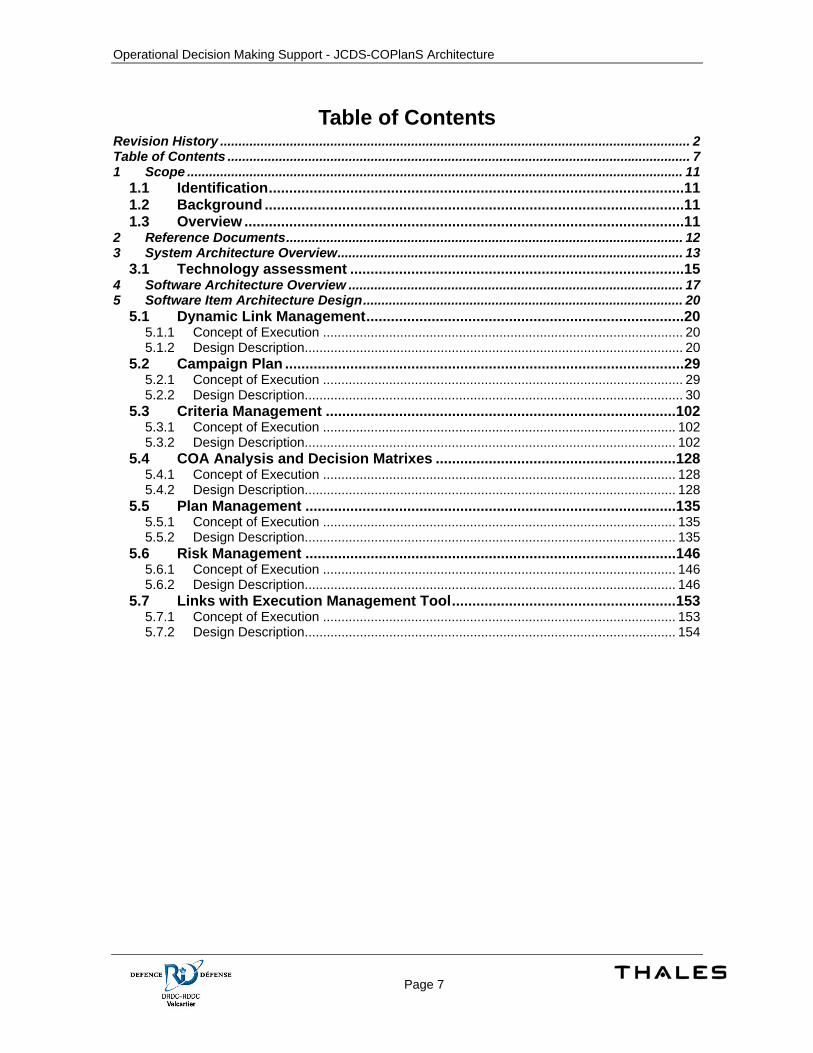
Table of Contents Revision History ................................................................................................................................ 2 Table of Contents .............................................................................................................................. 7 1 Scope ....................................................................................................................................... 11
1.1 Identification......................................................................................................11 1.2 Background .......................................................................................................11 1.3 Overview ............................................................................................................11
2 Reference Documents............................................................................................................ 12 3 System Architecture Overview.............................................................................................. 13
3.1 Technology assessment ..................................................................................15 4 Software Architecture Overview ........................................................................................... 17 5 Software Item Architecture Design....................................................................................... 20
5.1 Dynamic Link Management..............................................................................20 5.1.1 Concept of Execution .................................................................................................. 20 5.1.2 Design Description....................................................................................................... 20
5.2 Campaign Plan ..................................................................................................29 5.2.1 Concept of Execution .................................................................................................. 29 5.2.2 Design Description....................................................................................................... 30
5.3 Criteria Management ......................................................................................102 5.3.1 Concept of Execution ................................................................................................ 102 5.3.2 Design Description..................................................................................................... 102
5.4 COA Analysis and Decision Matrixes ...........................................................128 5.4.1 Concept of Execution ................................................................................................ 128 5.4.2 Design Description..................................................................................................... 128
5.5 Plan Management ...........................................................................................135 5.5.1 Concept of Execution ................................................................................................ 135 5.5.2 Design Description..................................................................................................... 135
5.6 Risk Management ...........................................................................................146 5.6.1 Concept of Execution ................................................................................................ 146 5.6.2 Design Description..................................................................................................... 146
5.7 Links with Execution Management Tool.......................................................153 5.7.1 Concept of Execution ................................................................................................ 153 5.7.2 Design Description..................................................................................................... 154
Operational Decision Making Support - JCDS-COPlanS Architecture
Page 8
Table of Figures Figure 1 – COPlanS System Architecture Overview......................................................................... 14 Figure 2 – Functional Architecture .................................................................................................... 17 Figure 3 – Inter-process Capabilities ................................................................................................ 19 Figure 4 - Problem [Error].................................................................................................................. 21 Figure 5 - Dependencies tab ............................................................................................................. 22 Figure 6 - Link Properties Screen...................................................................................................... 23 Figure 7 - Select an Analysis Element .............................................................................................. 24 Figure 8 - Validate / Invalidate Dialog ............................................................................................... 25 Figure 9 - Link Warning ..................................................................................................................... 25 Figure 10 - Problems Display [Warnings].......................................................................................... 26 Figure 11 - Problems Diaplay [Errors] ............................................................................................... 26 Figure 12 – Links Model Changes..................................................................................................... 27 Figure 13 - Graphics Layers.............................................................................................................. 31 Figure 14 - JHotDraw Figures ........................................................................................................... 33 Figure 15 - The graphics Drawing View ............................................................................................ 35 Figure 16 - Graphics Editor ............................................................................................................... 36 Figure 17 - View and Layer Drawing Classes ................................................................................... 37 Figure 18 - Persistent Figures ........................................................................................................... 38 Figure 19 - Tools ............................................................................................................................... 39 Figure 20 - Interactions with the Framework..................................................................................... 40 Figure 21 - Graphics Event Model..................................................................................................... 41 Figure 22 - Paint Sequence............................................................................................................... 44 Figure 23 – Animations ..................................................................................................................... 46 Figure 24 - Persistent Figures ........................................................................................................... 48 Figure 25 - Persistence Layer Extensions ........................................................................................ 53 Figure 26 - COPlanS Graphics Composites ..................................................................................... 54 Figure 27 - Composition Diagram ..................................................................................................... 60 Figure 28 - Model Diagrams.............................................................................................................. 61 Figure 29 - Default COG Analysis Layer........................................................................................... 61 Figure 30 - Model Link Support ......................................................................................................... 62 Figure 31 - Nodes.............................................................................................................................. 62 Figure 32 - Graphical Objects & Semantic Objects........................................................................... 63 Figure 33 - Layout Management ....................................................................................................... 63 Figure 34 - Remove Element ............................................................................................................ 64 Figure 35 - Remove Link ................................................................................................................... 64 Figure 36 - Center of Gravity Analysis Display ................................................................................. 66 Figure 37 - Hide/Show name............................................................................................................. 67 Figure 38 - Link Properties Screen.................................................................................................... 71 Figure 39 - Analysis Element Properties Screen .............................................................................. 71 Figure 40 - Tool Tip ........................................................................................................................... 72 Figure 41 - Model Changes............................................................................................................... 73 Figure 42 - Composition Diagram ..................................................................................................... 74 Figure 43 - Model Diagrams.............................................................................................................. 75 Figure 44 - Default DP Analysis Layer .............................................................................................. 75 Figure 45 - Model Link Support ......................................................................................................... 76 Figure 46 - Nodes.............................................................................................................................. 76 Figure 47 - Graphical Objects & Semantic Objects........................................................................... 77 Figure 48 - Layout Management ....................................................................................................... 78 Figure 49 - DPs Links Management.................................................................................................. 78 Figure 50 – Decisive Points Analysis Screen.................................................................................... 80 Figure 51 - Analysis Explorer & Tools............................................................................................... 82 Figure 52 – Magnifier Panel .............................................................................................................. 84 Figure 53 - DP Analysis Properties Screen....................................................................................... 85 Figure 54 - Centers of Gravity Screen .............................................................................................. 86 Figure 55 - Phases Screen................................................................................................................ 87
Operational Decision Making Support - JCDS-COPlanS Architecture
Page 9
Figure 56 – Lines of Operation Screen ............................................................................................. 88 Figure 57 – Objectives Screen.......................................................................................................... 88 Figure 58 – Effects Screen................................................................................................................ 89 Figure 59 – Tasks Screen ................................................................................................................. 90 Figure 60 – Decisive Point Cursor..................................................................................................... 91 Figure 61 – Branch Plan.................................................................................................................... 91 Figure 62 – Inserting DP before another DP..................................................................................... 91 Figure 63 – Inserting DP after another DP........................................................................................ 92 Figure 64 – Inserting DP before a Decision Point ............................................................................. 92 Figure 65 – Decision Point Cursor .................................................................................................... 94 Figure 66 – Decisive Point Properties Screen .................................................................................. 98 Figure 67 – Decision Point Properties Screen .................................................................................. 99 Figure 68 – Detailed Tooltip for a Decisive Point .............................................................................. 99 Figure 69 - Tooltip for a Decision Point........................................................................................... 100 Figure 70 - COG Tooltip .................................................................................................................. 100 Figure 71 - Tooltip for the Environmental Lines of Operation Area................................................. 100 Figure 72 - Tasks Area Tooltip ........................................................................................................ 100 Figure 73 - Changes to the Data Model .......................................................................................... 101 Figure 74 - Implementation Model................................................................................................... 103 Figure 75 - Screen Package Overview ........................................................................................... 104 Figure 76 - Operation Category Screen .......................................................................................... 105 Figure 77 - Force Employment Scenario Screen............................................................................ 106 Figure 78 - Operation Category Properties Screen......................................................................... 106 Figure 79 - Criteria Set Properties Screen ...................................................................................... 107 Figure 80 - Select Criterion Dialog .................................................................................................. 107 Figure 81 - Force Employment Scenario Properties Screen .......................................................... 108 Figure 82 - Evaluation Criteria After Action Reviews ...................................................................... 115 Figure 83 - Current Plan Criteria Management Screen .................................................................. 118 Figure 84 - Current Plan Criteria Lookup Dialog............................................................................. 118 Figure 85 - New Selection Screen................................................................................................... 119 Figure 86 - Search Criteria from Doctrine ....................................................................................... 122 Figure 87 - Search Criteria from Similar Operations ....................................................................... 123 Figure 88 - Plan Criteria Screen...................................................................................................... 124 Figure 89 - Rules Validation ............................................................................................................ 125 Figure 90 - COA Viability................................................................................................................. 126 Figure 91 - Plan Criteria [Properties Mode]..................................................................................... 129 Figure 92 - Plan Criteria [Cards Mode] ........................................................................................... 129 Figure 93 - COA Analysis Display................................................................................................... 130 Figure 94 – Decision Matrix (Descriptive) ....................................................................................... 131 Figure 95 - Decision Matrix (Numerical Analysis) ........................................................................... 132 Figure 96 - Decision Matrix (Result)................................................................................................ 133 Figure 97 - COA Analysis Model Changes ..................................................................................... 133 Figure 98 – Plan Copier – Class Diagram....................................................................................... 136 Figure 99 – PlanCopier – Source Code .......................................................................................... 138 Figure 100 – Plan Management Data Type .................................................................................... 138 Figure 101 – Plan Management Classes ........................................................................................ 139 Figure 102 – Date Format – Class Diagram ................................................................................... 139 Figure 103 – First Page of the Plan Creation Wizard...................................................................... 140 Figure 104 – New Page in the Plan Creation Wizard...................................................................... 140 Figure 105 – Automatic Page Filled in the Plan Creation Wizard ................................................... 141 Figure 106 – Time Line Widget ....................................................................................................... 141 Figure 107 – D-Day Format Display................................................................................................ 142 Figure 108 – Relative Time Line Widget ......................................................................................... 142 Figure 109 – Time Line Widget in COA Screens ............................................................................ 143 Figure 110 – Critical Timing Page of the Plan Creation Wizard (greyed out) ................................. 143 Figure 111 – Critical Timing Page of the Plan Creation Wizard...................................................... 144 Figure 112 – Wikipedia Excerpt ...................................................................................................... 145
Operational Decision Making Support - JCDS-COPlanS Architecture
Page 10
Figure 113 - Threats List ................................................................................................................. 147 Figure 114 - Threat Properties Screen [Analysis] ........................................................................... 147 Figure 115 - Threat Properties Screen [Mitigation] ......................................................................... 148 Figure 116 - Risk Editor................................................................................................................... 149 Figure 117 - Risk Matrix .................................................................................................................. 150 Figure 118 – Execution Management – Activity Diagram ............................................................... 154 Figure 119 – JCDS integration – Component Diagram................................................................... 155 Figure 120 – JCDS and COPlanS Web Service integration ........................................................... 158
Table of Tables
Table 1 – COPlanS Client – List of Products .................................................................................... 15 Table 2 – COPlanS Server – List of Products................................................................................... 15 Table 3 - Link properties screen........................................................................................................ 22 Table 4 - Status History..................................................................................................................... 22 Table 5 - Type Enumeration.............................................................................................................. 27 Table 6 – Status Enumeration........................................................................................................... 28 Table 7-Operation Category Properties .......................................................................................... 109 Table 8- Criterion Properties ........................................................................................................... 109 Table 9-Factor Properties................................................................................................................ 111 Table 10-Criteria Set Properties...................................................................................................... 111 Table 11-Criteria Set Criterion Properties ....................................................................................... 113 Table 12-Force Employment Scenario Properties .......................................................................... 113 Table 13 - Evaluation Properties..................................................................................................... 117 Table 14 - Plan Properties............................................................................................................... 120 Table 15 - Operation Properties...................................................................................................... 120 Table 16 - Plan Criterion Properties................................................................................................ 120 Table 17 - Criterion Rule Properties................................................................................................ 125 Table 18 – COAViability Properties................................................................................................. 126 Table 19 - Selection Description ..................................................................................................... 131 Table 20 – Evaluation Properties .................................................................................................... 134 Table 21 – Plan Criterion Properties ............................................................................................... 134 Table 22 – Relative Date Format .................................................................................................... 144 Table 23 - Threat Properties ........................................................................................................... 147 Table 24 - Threat Properties [Mitigation]......................................................................................... 148 Table 25 - Risk Editor Actions ......................................................................................................... 149 Table 26 - Risk Management Data Elements ................................................................................. 150 Table 27 – PlanService Interface .................................................................................................... 155 Table 28 – Notification Interface...................................................................................................... 156 Table 29 – Document Repository Interface..................................................................................... 156
Operational Decision Making Support - JCDS-COPlanS Architecture
Page 11
1 Scope
1.1 Identification This document describes the design of components developed in the scope of the contract of the integration of COPlanS in JCDS. This architecture locates those new components in COPlanS and their usage inside of the Operational Planning Process (OPP).
1.2 Background COPlanS is an evolutionary tool used to produce plans according to the CF-OPP. COPlanS has been developed over many years. COPlanS is composed of many modules used to help planners to perform specific tasks inside the planning process.
JCDS is an initiative having the aim to access disparate information from many systems through a common infrastructure. This ensures the interoperability between systems hosted on this platform. COPlanS is one of these targeted systems. Most COPlanS components already existed before the initiation of JCDS work. The current document is limited to the architecture and design of COPlanS within the scope of the JCDS work.
1.3 Overview This document aims at establishing the basis for adding and enhancing the operational decision making support in COPlanS as defined by RDDC-Valcartier.
The document assumes that the reader has knowledge of COPlanS features and the framework used to build the different components.
This document describes a limited selection of concepts that have been described in the present contract. Some of those concepts have been studied in the 1562C-003.STUDY-DM document and refined in the Operational Concept Description study. This document proposes a partial implementation of them.
The structure and content of this document is based on IEA 12207 documents. It groups elements about SARAD, SAD, SDD and SIDD of this methodology.

Operational Decision Making Support - JCDS-COPlanS Architecture
Page 12
2 Reference Documents COPlanS Environment.vsd
COPlanS SoftwareComponent List.doc
JCDS Investigation of Concepts to Support Operational Decision Making Study, document number 1562C-003.STUDY-DM Rev. 02 dated 05 May 2008.
JCDS Operational Concept Description, document number 1562C.006-OCD Rev. 01 dated 31 March 2009.
JCDS21Worshop-Feb08-Concepts to support Operational DM-v1-with page numbers.ppt
Operational Decision Making Support - JCDS-COPlanS Architecture
Page 13
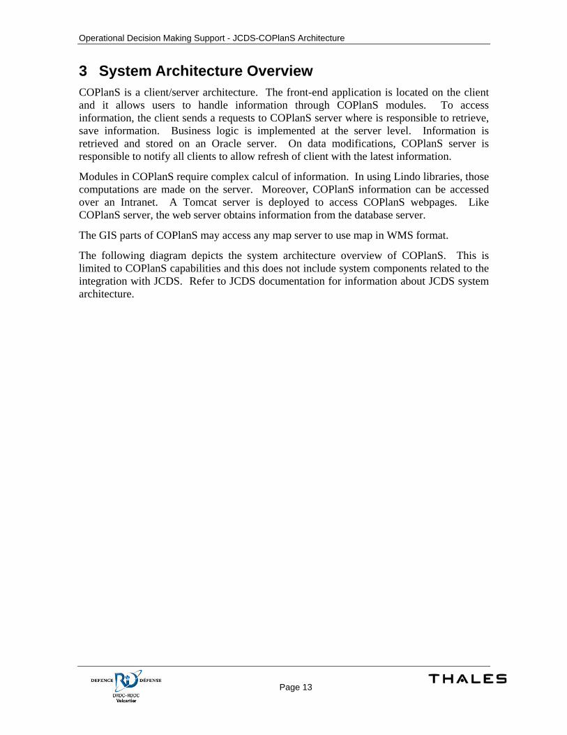
3 System Architecture Overview COPlanS is a client/server architecture. The front-end application is located on the client and it allows users to handle information through COPlanS modules. To access information, the client sends a requests to COPlanS server where is responsible to retrieve, save information. Business logic is implemented at the server level. Information is retrieved and stored on an Oracle server. On data modifications, COPlanS server is responsible to notify all clients to allow refresh of client with the latest information.
Modules in COPlanS require complex calcul of information. In using Lindo libraries, those computations are made on the server. Moreover, COPlanS information can be accessed over an Intranet. A Tomcat server is deployed to access COPlanS webpages. Like COPlanS server, the web server obtains information from the database server.
The GIS parts of COPlanS may access any map server to use map in WMS format.
The following diagram depicts the system architecture overview of COPlanS. This is limited to COPlanS capabilities and this does not include system components related to the integration with JCDS. Refer to JCDS documentation for information about JCDS system architecture.
Operational Decision Making Support - JCDS-COPlanS Architecture
Page 14
1
Figure 1 – COPlanS System Architecture Overview
The following is to be considered:
• The servers identified represent a logical distribution of COPlanS components. The physical implementation may differ. In the other words, servers may be deployed on the same hardware.
• The Oracle Database is installed with the default configurations. If the installation differs, the application can be configured.
1 Extract from COPlanS Environment.vsd used in the context of COPlanS accreditation and environment preparation for the
trial.
Operational Decision Making Support - JCDS-COPlanS Architecture
Page 15
3.1 Technology assessment The following table enumerates technology required to support COPlanS. This list is limited to COPlanS software item. This excludes products required to support components of JCDS.
Table 1 – COPlanS Client – List of Products
Product Description Provider Comment
Coplans Client DRDC JIDE 2.2.4 Advanced graphical
user interface widgets Jide
LuciadMap 5.3.08 GIS Support Luciad The GIS in Coplans will not work at all if the license is not valid.
JViews 5.5 Gantt and Diagramming Support
ILog There is only a message saying that a deployment license is required but the tools will still be available at runtime.
Comparaison Decision Aid Support DRDC Aspose Slides .Net & Java
MS PowerPoint Document Generation
Aspose
JFDraw Java Based Graphics application and library package (Used only in Coplans 1.5)
JFImagine Open Source
Looks 2.1.4 Application Look&Feels
JGoodies
JavaBean Activation Framework (JAF) 1.1.0
Sun Included with J2SE 6
XStream 1.1.2 Xml Serialization tool Codehaus Open Source XPP 3.1.1.3.4 Xml Pull Parser Java Advanced Imaging (JAI) 1.1.3
Image processing toolkit
Sun
Java Mail Api Sun JRE 1.6 (Sun Microsystems Inc.)
Java Runtime Edition Sun
Windows 2000 SP3 Operating System Microsoft Internet Explorer or any WW3 Browser
Office 2003 or later Microsoft Used to view/edit generated document
JHotDraw 7.1 Graphic library JHotDraw.org (SourceForge)
Open Source
Table 2 – COPlanS Server – List of Products
Product Description Provider Comment
Coplans Server DRDC Oracle 9i or 10g DBMS Data Persistence Oracle JRE 1.6 Java Runtime Edition Sun
Microsystems

Operational Decision Making Support - JCDS-COPlanS Architecture
Page 16
Product Description Provider Comment
Lindo 6.1 Sensibility Analysis Lindo Systems Oracle 9i or 10g JDBC Driver Tomcat 5.0 or later Web Access and Services Apache Any WMS compliant map server
Access and Load Geographical Maps
Operational Decision Making Support - JCDS-COPlanS Architecture
Page 17
4 Software Architecture Overview JCDS required modifications to COPlanS by extending existing functionalities and creating new ones. Basically, most new capabilities are not directly related together. In fact, COPlanS provides a set tools used at different stage of the Operational Planning Process (OPP). These new components are added and mixed with existing COPlanS components through the different stages of the OPP spectrum. The architecture below depicts the new capabilities in COPlanS.
Figure 2 – Functional Architecture
At the initiation stage, The Plan Management allows plan creations based on existing plans (OPLAN) or contingency plans (CONPLAN). Through the plan creation wizard, the plan may be created based on these. Also, the wizard allows inheritance by copying or linking to elements of the parent plan. These links are supported through all modules in COPlanS via the Dynamic Link Management capability. On the plan creation, the Plan Service sends a notification to the JCDS Enterprise Service Bus (ESB) to inform a new plan is now available. External software on JCDS like EMPA may obtain information about plans by sending requests to the ESB where the request is routed and processed by the Plan Service in COPlanS. Also, a document workspace is created in JCDS to put documents produced by COPlanS in this repository. The documents are sent to this repository anytime in the process.
During the orientation phase in the OPP, elements influencing the plans are defined. Criteria used for COAs comparison is one of those elements. Despite COPlanS allowing evaluation criteria to be defined anytime in the process, this information is closely related to the orientation of the commander. Past missions may influence actual plans. The criteria used to evaluate can be searched and copied to new plans via the Evaluation Criteria Management capability. Some criteria have close to the same meaning and should

Operational Decision Making Support - JCDS-COPlanS Architecture
Page 18
not be used in tandem in the evaluation of COAs. For example, Simplicity and Complexity evaluate the same thing. To avoid over-evaluations, the Evaluation Criterion Validation allows detection of these cases.
The orientation phase is an activity to brainstorm about the plan before defining possible scenarios (COAs). Possible centres of gravity with their critical capability, requirements and vulnerabilities are identified. To take advantage or secure them, decisive points are defined. The COG Analysis is the tool to brainstorm on these elements in a graphical environment. After, the decisive points are sequenced on lines of operation via the Decisive Point Analysis.
In the orientation stage, COPlanS provides a set of tools to define various kinds of elements having impacts on decisions related to the plan. Those elements may be factors of risk. The Risk Management allows identification and analysis of risks. Also, it allows mitigation of them when COAs and plans are refined through next steps of the OPP.
At the end of the COA development activity, the COAs are developed. The COA Viability allows validation of each COA. Each COA must respect a set of criteria to be considered valid. When they are valid, COA Analysis provides the user the result of each COA according to evaluation criteria. The decision matrix provides the capability to compare COAs based on these criteria.
Once the plan is completed and executed as an order, the information is reviewed for what was good and bad using After Action Review. This improves planning for next operations by consulting action reviews of evaluation criteria before copying them.
Using new capabilities and JCDS services, COPlanS interacts with external processes. Mainly, COPlanS defines elements of a plan. The produced plan becomes an order consumed by other services on the JCDS platform. Mainly, EMPA is the tool consuming the order for the battle management. During the execution of the order, the situation may change and a re-planning may be required. The Plan service is responsible to manage this request.
After the order is executed, a debriefing is done. Strengths and weaknesses are identified and captured with the After Action Review for next planning cycle. Using previous experiences, users may adapt their plan based on similar situations (plans) in the past.
JCDS provides a collaborative directory. All documents produced by COPlanS (Planning) and stored on the JCDS repository are accessible by other tools and processes related to JCDS.
Operational Decision Making Support - JCDS-COPlanS Architecture
Page 19
Orde
r
Figure 3 – Inter-process Capabilities
Operational Decision Making Support - JCDS-COPlanS Architecture
Page 20
5 Software Item Architecture Design
5.1 Dynamic Link Management
5.1.1 Concept of Execution COPlanS contains various information to consider while the planning is performed. These elements may be related to each other. This means: an information element captured in the system may influence another defined in the system. For example, a constraint related to the operation may increase the severity of a risk item. A the operational theatre evolves over time, the information releated elements in COPlanS that describe this situation need to be updated too. Because information can be new, modified or become obsolete, the system shall identify other information related to those changes. In the other words, a decision made about an element of information at a specific moment may require to be revisited when the situation changes.
To know if an element of information may impact others, the system shall allow creation of links related to information. When an information element is modified, all related elements are not necessarily revisited immediately. Thus, it is important the system provides a way to identify what has been reviewed and what has not. COPlanS provides a mechanism to invalidate links of an information element on modification. This allows users to identify possible impacts and validate related linked elements.
Information can be related to another element of the same plan or can inherit from a parent operation. In the case of parent relationship, those elements are created and linked on plan creation (creation wizard) or can be imported later. Relations between elements of a plan are manually defined by users.
The dynamic link management is not related to a specific activity in the planning process. Any element in COPlanS is subject to be linked to other elements anytime during the planning.
5.1.2 Design Description The CFOPP elements require a link enforcement concept to keep integrity between elements. By establishing links, it will be difficult to track the impact a planning element may have on other element. The links types we want to support are:
• Links supporting or refuting the existence of an element
• Links indicating an influence between elements
• Links representing a sequence in time
• Links representing a refinement of an object
5.1.2.1 Link Management Detailed Design
5.1.2.1.1 Interaction
Operational Decision Making Support - JCDS-COPlanS Architecture
Page 21
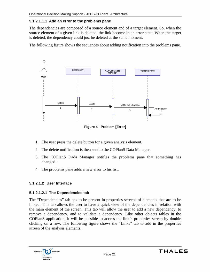
5.1.2.1.1.1 Add an error to the problems pane
The dependencies are composed of a source element and of a target element. So, when the source element of a given link is deleted, the link become in an error state. When the target is deleted, the dependency could just be deleted at the same moment.
The following figure shows the sequences about adding notification into the problems pane.
Figure 4 - Problem [Error]
1. The user press the delete button for a given analysis element.
2. The delete notification is then sent to the COPlanS Data Manager.
3. The COPlanS Dada Manager notifies the problems pane that something has changed.
4. The problems pane adds a new error to his list.
5.1.2.1.2 User Interface
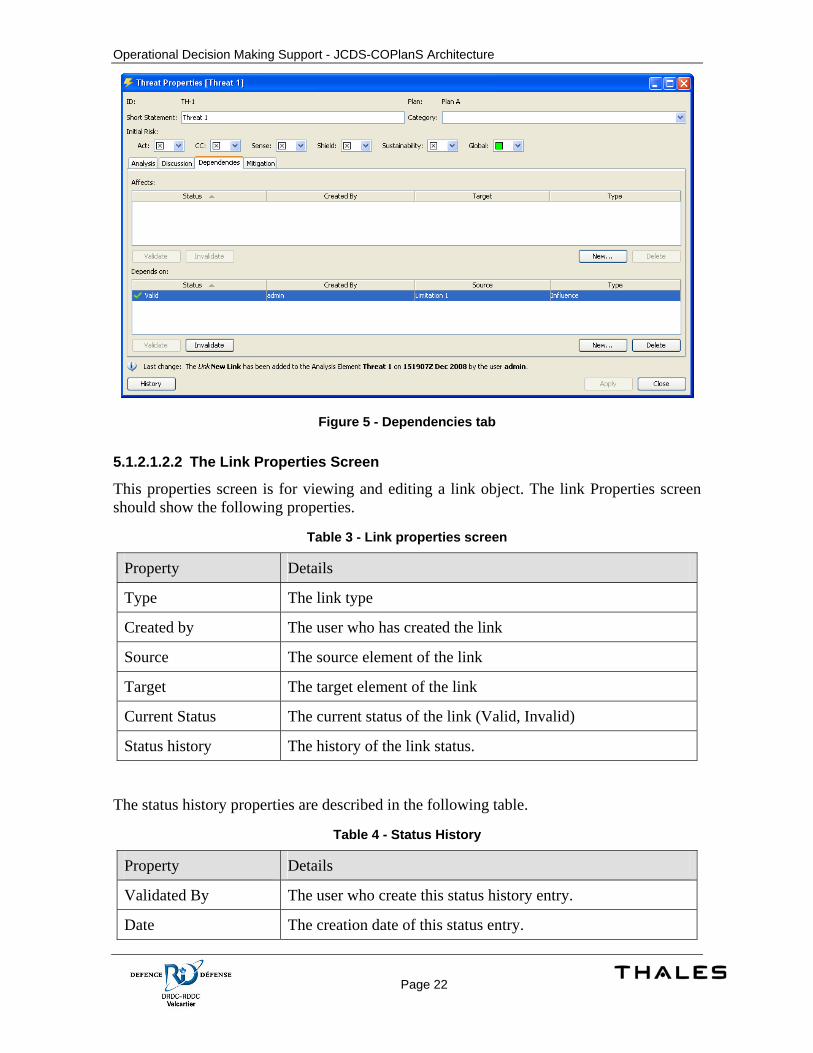
5.1.2.1.2.1 The Dependencies tab
The “Dependencies” tab has to be present in properties screens of elements that are to be linked. This tab allows the user to have a quick view of the dependencies in relation with the main element of the screen. This tab will allow the user to add a new dependency, to remove a dependency, and to validate a dependency. Like other objects tables in the COPlanS application, it will be possible to access the link’s properties screen by double clicking on a row. The following figure shows the “Links” tab to add in the properties screen of the analysis elements.
Operational Decision Making Support - JCDS-COPlanS Architecture
Page 22
Figure 5 - Dependencies tab
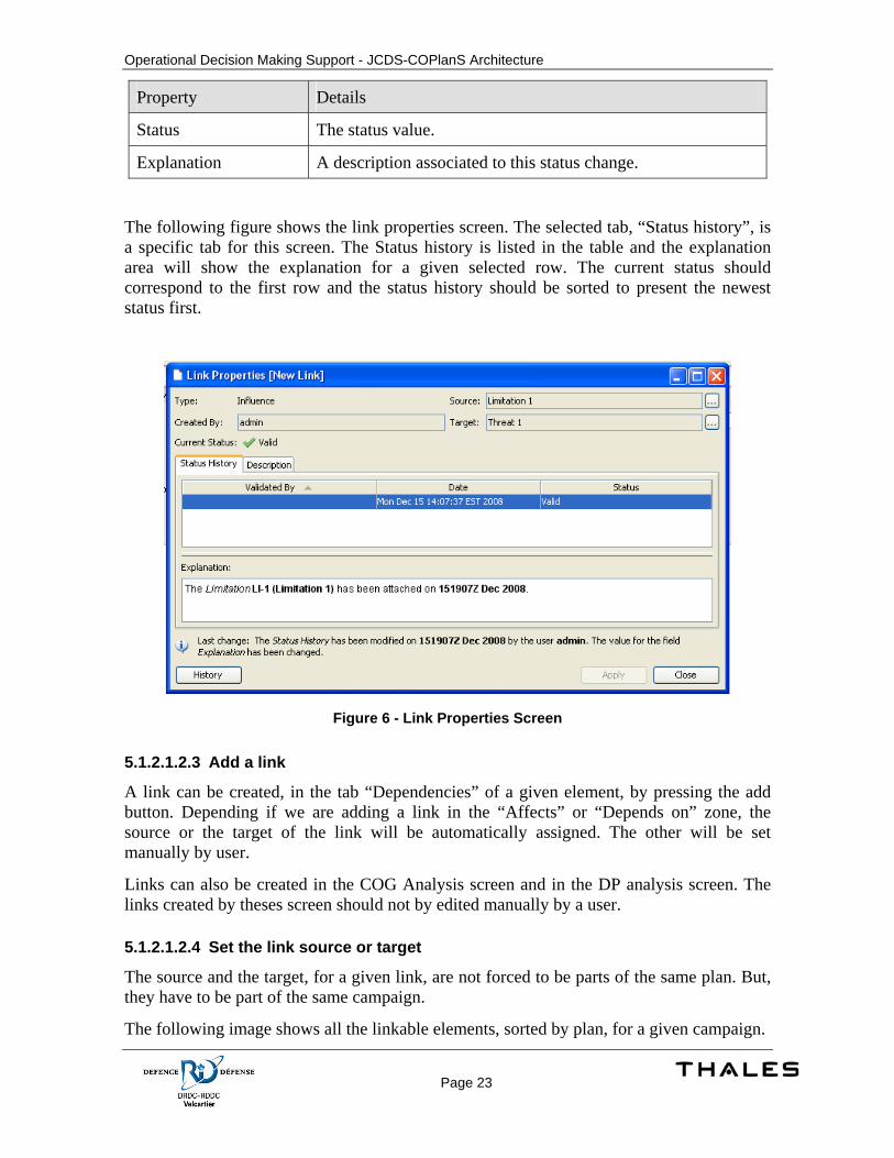
5.1.2.1.2.2 The Link Properties Screen
This properties screen is for viewing and editing a link object. The link Properties screen should show the following properties.
Table 3 - Link properties screen
Property Details
Type The link type
Created by The user who has created the link
Source The source element of the link
Target The target element of the link
Current Status The current status of the link (Valid, Invalid)
Status history The history of the link status.
The status history properties are described in the following table.
Table 4 - Status History
Property Details
Validated By The user who create this status history entry.
Date The creation date of this status entry.
Operational Decision Making Support - JCDS-COPlanS Architecture
Page 23
Property Details
Status The status value.
Explanation A description associated to this status change.
The following figure shows the link properties screen. The selected tab, “Status history”, is a specific tab for this screen. The Status history is listed in the table and the explanation area will show the explanation for a given selected row. The current status should correspond to the first row and the status history should be sorted to present the newest status first.
Figure 6 - Link Properties Screen
5.1.2.1.2.3 Add a link
A link can be created, in the tab “Dependencies” of a given element, by pressing the add button. Depending if we are adding a link in the “Affects” or “Depends on” zone, the source or the target of the link will be automatically assigned. The other will be set manually by user.
Links can also be created in the COG Analysis screen and in the DP analysis screen. The links created by theses screen should not by edited manually by a user.
5.1.2.1.2.4 Set the link source or target
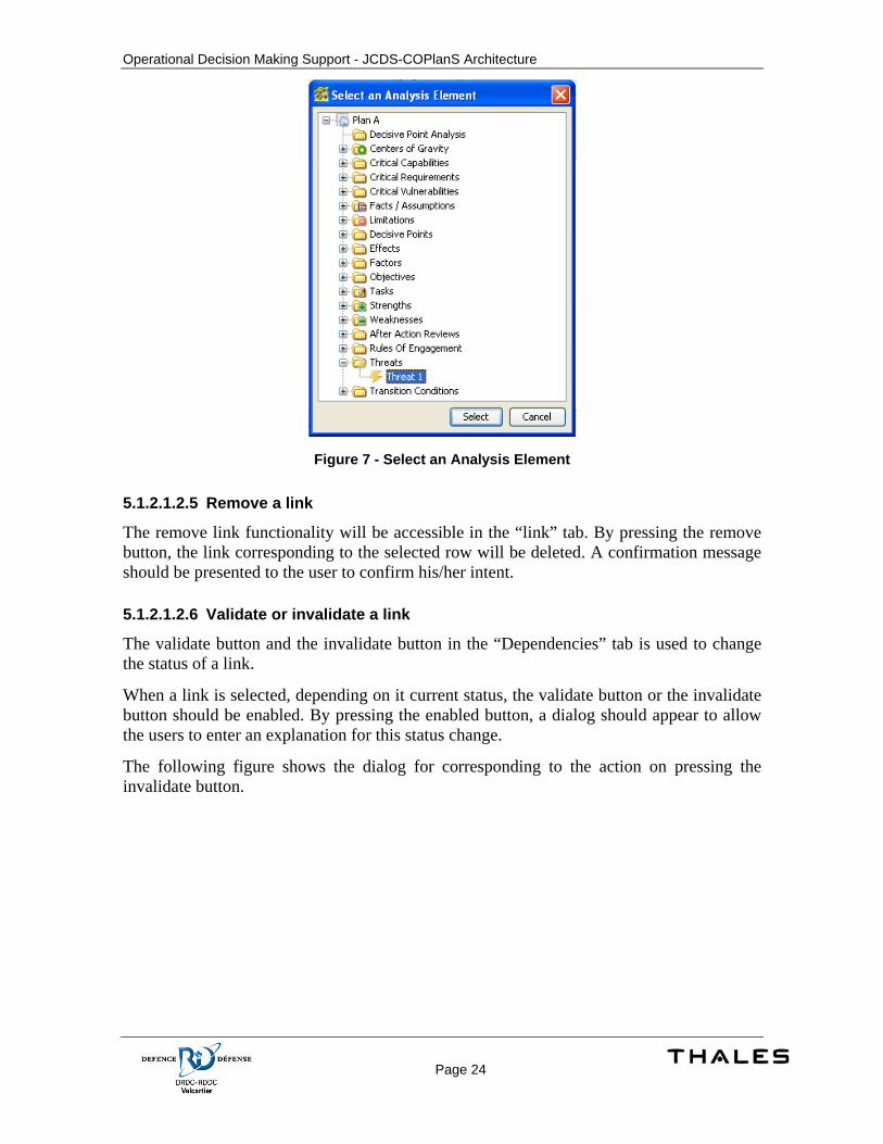
The source and the target, for a given link, are not forced to be parts of the same plan. But, they have to be part of the same campaign.
The following image shows all the linkable elements, sorted by plan, for a given campaign.
Operational Decision Making Support - JCDS-COPlanS Architecture
Page 24
Figure 7 - Select an Analysis Element
5.1.2.1.2.5 Remove a link
The remove link functionality will be accessible in the “link” tab. By pressing the remove button, the link corresponding to the selected row will be deleted. A confirmation message should be presented to the user to confirm his/her intent.
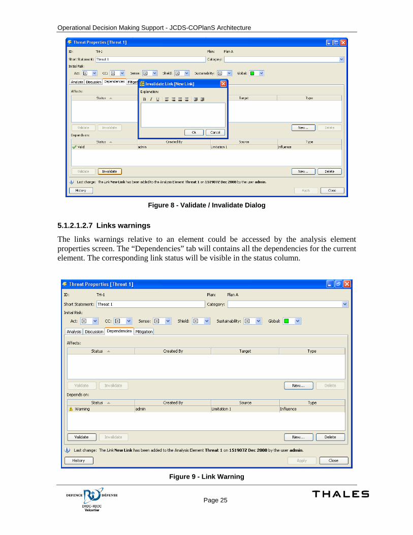
5.1.2.1.2.6 Validate or invalidate a link
The validate button and the invalidate button in the “Dependencies” tab is used to change the status of a link.
When a link is selected, depending on it current status, the validate button or the invalidate button should be enabled. By pressing the enabled button, a dialog should appear to allow the users to enter an explanation for this status change.
The following figure shows the dialog for corresponding to the action on pressing the invalidate button.
Operational Decision Making Support - JCDS-COPlanS Architecture
Page 25
Figure 8 - Validate / Invalidate Dialog
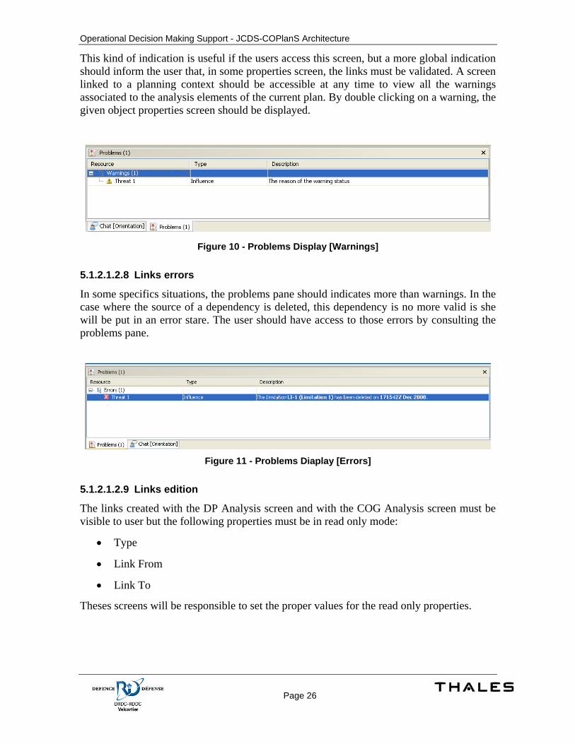
5.1.2.1.2.7 Links warnings
The links warnings relative to an element could be accessed by the analysis element properties screen. The “Dependencies” tab will contains all the dependencies for the current element. The corresponding link status will be visible in the status column.
Figure 9 - Link Warning
Operational Decision Making Support - JCDS-COPlanS Architecture
Page 26
This kind of indication is useful if the users access this screen, but a more global indication should inform the user that, in some properties screen, the links must be validated. A screen linked to a planning context should be accessible at any time to view all the warnings associated to the analysis elements of the current plan. By double clicking on a warning, the given object properties screen should be displayed.
Figure 10 - Problems Display [Warnings]
5.1.2.1.2.8 Links errors
In some specifics situations, the problems pane should indicates more than warnings. In the case where the source of a dependency is deleted, this dependency is no more valid is she will be put in an error stare. The user should have access to those errors by consulting the problems pane.
Figure 11 - Problems Diaplay [Errors]
5.1.2.1.2.9 Links edition
The links created with the DP Analysis screen and with the COG Analysis screen must be visible to user but the following properties must be in read only mode:
• Type
• Link From
• Link To
Theses screens will be responsible to set the proper values for the read only properties.
Operational Decision Making Support - JCDS-COPlanS Architecture
Page 27
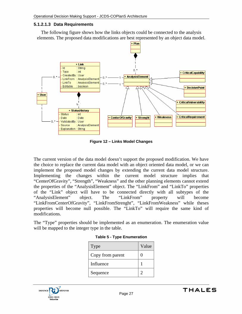
5.1.2.1.3 Data Requirements
The following figure shows how the links objects could be connected to the analysis elements. The proposed data modifications are best represented by an object data model.
Figure 12 – Links Model Changes
The current version of the data model doesn’t support the proposed modification. We have the choice to replace the current data model with an object oriented data model, or we can implement the proposed model changes by extending the current data model structure. Implementing the changes within the current model structure implies that “CenterOfGravity”, “Strength”, “Weakness” and the other planning elements cannot extend the properties of the “AnalysisElement” object. The “LinkFrom” and “LinkTo” properties of the “Link” object will have to be connected directly with all subtypes of the “AnalysisElement” object. The “LinkFrom” property will become “LinkFromCenterOfGravity”, “LinkFromStrenght”, “LinkFromWeakness” while theses properties will become null possible. The “LinkTo” will require the same kind of modifications.
The “Type” properties should be implemented as an enumeration. The enumeration value will be mapped to the integer type in the table.
Table 5 - Type Enumeration
Type Value
Copy from parent 0
Influence 1
Sequence 2
Operational Decision Making Support - JCDS-COPlanS Architecture
Page 28
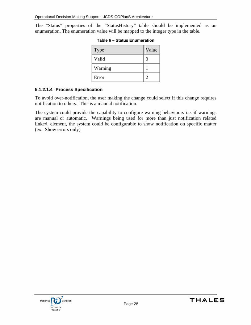
The “Status” properties of the “StatusHistory” table should be implemented as an enumeration. The enumeration value will be mapped to the integer type in the table.
Table 6 – Status Enumeration
Type Value
Valid 0
Warning 1
Error 2
5.1.2.1.4 Process Specification
To avoid over-notification, the user making the change could select if this change requires notification to others. This is a manual notification.
The system could provide the capability to configure warning behaviours i.e. if warnings are manual or automatic. Warnings being used for more than just notification related linked, element, the system could be configurable to show notification on specific matter (ex. Show errors only)
Operational Decision Making Support - JCDS-COPlanS Architecture
Page 29
5.2 Campaign Plan
5.2.1 Concept of Execution The campaign plan is divided into two distinct activities: Centre of Gravity Analysis and Decisive Point Analysis. The first one identifies critical capabilities, requirements and vulnerabilities. This is used to determine a centre of gravity to attack and one to protect. Based on those elements, decisive points are also identified to be achieved allowing to attack and protect centre of gravities and to complete the mission successfully.
During the Decisive Point Analysis, decisive points are sequenced in time. Decisive points are the set of mile stones to achieve to accomplish the mission successfully. The final result of this analysis can be considered as the high level view of the mission.
5.2.1.1 Centre of Gravity Analysis The Centre of Gravity analysis is a part of the Mission Analysis activity in Operational Planning Process. Each mission is initiated with the commander intent. Based on the commander intent, the end-state of the mission is determined with its transition criteria. Those criteria are used as metric to determine is the mission is a success or it fails.
According to those statements and various information about the operational theatre, potential centre of gravities are identified. A set of enemy and friendly centre of gravities are identified
An enemy centre of gravity means what my resources must focus to eliminate or destroy to complete the mission successfully. In the same way, a friendly centre of gravity is what my resources must focus to protect to ensure the mission can be accomplished well.
At the end of the analysis only one friendly and one enemy centre of gravity will be chosen to be the objective where efforts will focus to protect and destroy.
Based on elements on the theatre, critical capabilities of our troups and enemy troups are identified. Those capabilities are possible when critical requirements are met. From those requirements, vulnerabilities can be identified. To secure or take advantage of vulnerabilities decisive points are defined.
The Centre of Gravity Analysis allows identifying and linking of those elements. At the end of the analysis, a set of decisive points are defined.
5.2.1.2 Decisive Points Analysis The Decisive Points Analysis is a task overlapping the Mission Analysis and COA Development in planning process. This analysis use the decisive points produced during the Centre of Gravity Analysis as input information.
Decisive Points Analysis allows sequencing of Decisive Points in a logical way to achieve them to protect and attack both Centers of Gravity. The sequencing is made on many lines of operation. Each line of operation is related to a specific functionality in the organization.
Operational Decision Making Support - JCDS-COPlanS Architecture
Page 30
Examples: Combat, Support, Information management etc. This may also correspond to each Canadian force (Air, Navy, Land and Joint).
Phases can also be defined to synchronize decisive points between lines of operation. Phases indicate to a line of operation to wait completion of decisive points on other lines of operation before performing next decisive points. For each or whole lines of operation, objectives can be defined for each phase. Objectives are metrics used to validate if decisive points are completed
Each line of operation contains the sequence of decisive points to perform. Alternate sequence may be defined if the situation is in a certain state. This alternate path named branch plan is performed according to a specific condition.
The decisive point analysis provides an overview on the mission where each decisive point will be detailed in many tasks during the COA Development activity.
5.2.2 Design Description
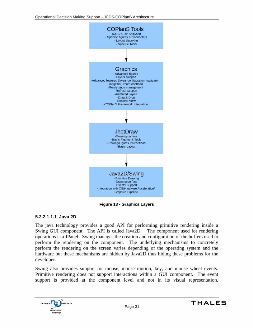
5.2.2.1 Overview Graphical tools such as the Center of gravity analysis and the Decisive Points analysis tools are designed to share a common set of features. An external library ‘JHotDraw’ is used to provide basic diagramming features such as a drawing canvas, figures, connectors and tooling (figure selection, creation …).
To meet the requirements for the COG analysis and DP analysis, new functionalities are required by the graphical layer which are not provided by JHotDraw or simply too specific to the required functionalities. The extended library is called ‘graphics’. Other objectives for this library are:
• Allow reuse of diagramming functionalities.
• Leverage the COPlanS’ framework to automate the interactions with the database layer and the GUI framework features (focus management, shared actions integration such as delete, workspace integration)
The roles of each component are defined in the following sections.
5.2.2.1.1 Graphics Layers
The following figure shows the hierarchy between the different components. It is important to note that these layers don’t hide the underlying layers. For example, the COG analysis tool could use primitive drawing features directly on the Java 2D surface. The hierarchy presented here should be seen as enhancements over the underlying layers with the exception of Java2D on which all graphics operations rely.
Operational Decision Making Support - JCDS-COPlanS Architecture
Page 31
JhotDraw-Drawing canvas
-Basic Figures & Tools-Drawing/Figures Interactions
-Basic Layout
Java2D/Swing- Primitive Drawing-Drawing surface-Events Support
-Integration with OS/Hardware Acceleration/Graphics Pipeline
Graphics-Advanced figures-Layers Support
-Advanced features (layers configuration, navigator, magnifier, zoom controls)
-Persistence management-Refresh support-Animated Layout
-Drag & Drop-Explorer View
-COPlanS Framework Integration
COPlanS Tools (COG & DP Analysis)
- Specific figures & Connectors- Layout algorythn
- Specific Tools
Figure 13 - Graphics Layers
5.2.2.1.1.1 Java 2D
The java technology provides a good API for performing primitive rendering inside a Swing GUI component. The API is called Java2D. The component used for rendering operations is a JPanel. Swing manages the creation and configuration of the buffers used to perform the rendering on the component. The underlying mechanisms to concretely perform the rendering on the screen varies depending of the operating system and the hardware but these mechanisms are hidden by Java2D thus hiding these problems for the developer.
Swing also provides support for mouse, mouse motion, key, and mouse wheel events. Primitive rendering does not support interactions within a GUI component. The event support is provided at the component level and not in its visual representation.
Operational Decision Making Support - JCDS-COPlanS Architecture
Page 32
For example, drawing a rectangle on the graphics object does not allow interaction with the rectangle and performing a color change is not possible without redrawing the rectangle over the previous rectangle. When a primitive object is drawn, it is rendered on the surface but any information regarding the shape, size or color is not preserved. This is equivalent to manually drawing a rectangle on a piece of paper using a pen.
5.2.2.1.1.2 JHotDraw
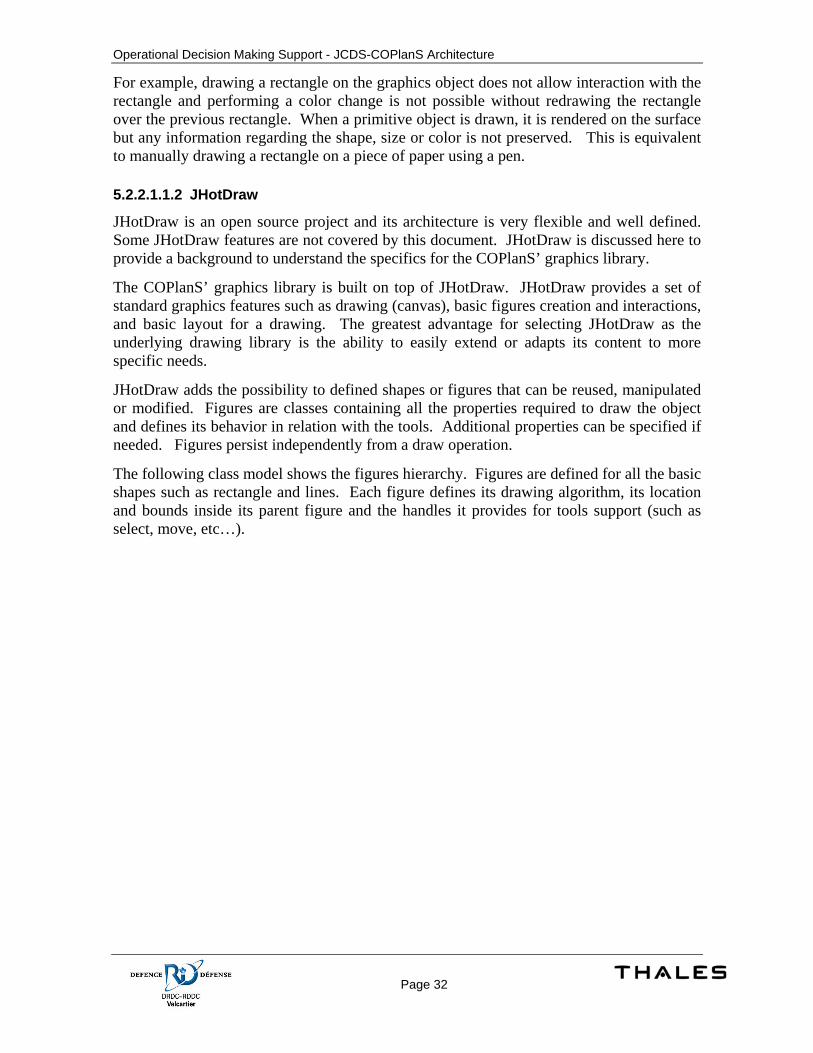
JHotDraw is an open source project and its architecture is very flexible and well defined. Some JHotDraw features are not covered by this document. JHotDraw is discussed here to provide a background to understand the specifics for the COPlanS’ graphics library.
The COPlanS’ graphics library is built on top of JHotDraw. JHotDraw provides a set of standard graphics features such as drawing (canvas), basic figures creation and interactions, and basic layout for a drawing. The greatest advantage for selecting JHotDraw as the underlying drawing library is the ability to easily extend or adapts its content to more specific needs.
JHotDraw adds the possibility to defined shapes or figures that can be reused, manipulated or modified. Figures are classes containing all the properties required to draw the object and defines its behavior in relation with the tools. Additional properties can be specified if needed. Figures persist independently from a draw operation.
The following class model shows the figures hierarchy. Figures are defined for all the basic shapes such as rectangle and lines. Each figure defines its drawing algorithm, its location and bounds inside its parent figure and the handles it provides for tools support (such as select, move, etc…).
Operational Decision Making Support - JCDS-COPlanS Architecture
Page 33
Figure 14 - JHotDraw Figures
The blue classes define the drawings for JHotDraw. JHotDraw defines drawing as figures which can contains and manage other figures. This role is defined as a composite figure. A composite figure offer mechanisms to add or remove figures. The composite figure uses various layout algorithms to position its children figures inside its boundaries. Most composite figure implementations use the coordinates and preferred size provided by the children figures to perform the layout. A composite figure is also responsible for delegating events to its children figures.
Attributed figures are figures extending the abstract class AbstractAtttributedFigure. Attributed figures are figures managing a set of properties defined as attribute. An Attribute is defined by a key (or identifier) and a value. Examples of attributes are fill color, text color or stroke color. Attributes are used to provide generic access to properties regarding of the figure.
It is important to note that the library does not hide java 2D primitive operations. It is possible to draw directly using java2D if needed.
5.2.2.1.1.3 COPlanS’ graphics library & Features
The graphics library and the COG & DP analysis features extend components defined by JHotDraw to provide additional features. New Figures, attributes, a specific drawing object, new tools, drag & drop and layer support are some of the added features.
Operational Decision Making Support - JCDS-COPlanS Architecture
Page 34
In addition, it provides support for an explorer (tree) and a set of standard tools for drawing such as:
• Navigator (Allows change of the drawing’s visible area, zoom in, zoom out and fit drawing size to visible area)
• Layer managements (Add, remove, change order and rename layers)
• Magnifier (Provide a fixed scale view of the drawing at the mouse pointer’s location for easier reading of the drawing on zoom out)
Note that the JHotDraw functionalities are available to specific graphics features such as the Center of Gravity analysis and Decisive Point analysis.
The graphics components are discussed in the following sections.
5.2.2.2 Graphics Package Detailed Design
5.2.2.2.1 Classes
The graphics package defines specialized classes extending the components defined in JHotDraw.
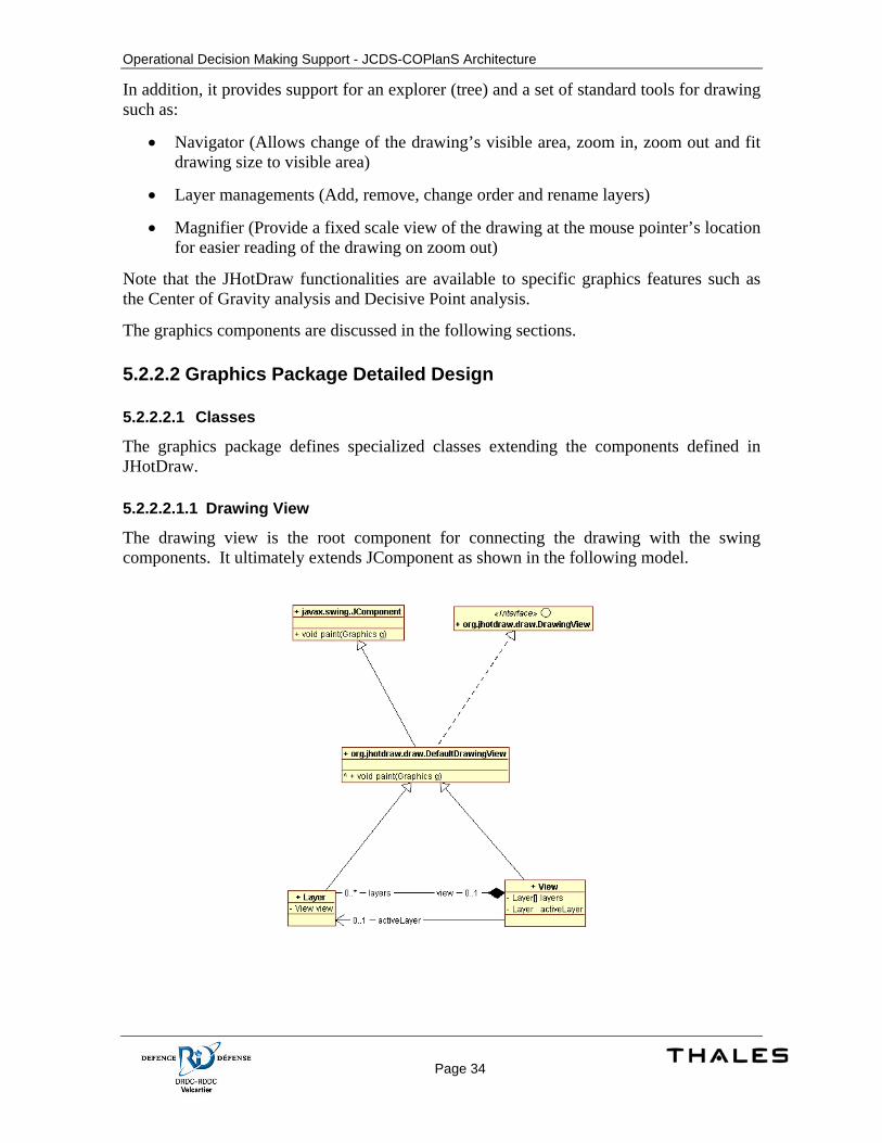
5.2.2.2.1.1 Drawing View
The drawing view is the root component for connecting the drawing with the swing components. It ultimately extends JComponent as shown in the following model.
Operational Decision Making Support - JCDS-COPlanS Architecture
Page 35
Figure 15 - The graphics Drawing View
The drawing view handles the basic paint and print operation for the figures by overriding the paint method defined on the swing components. This method provides a Graphics2D object managed and created by java2D/swing. The painting is performed by using the primitive methods defined on the graphics object. The drawing view separates the paint operation in 5 steps:
• The background
• The constrainers
• The drawing
• The handles
• The tools
The coordinate system used by swing depends of the screen resolution and does not support precision for swing components’ coordinates. In the context of a drawing, precision is important. Precision on coordinates or any other values required for rendering the figure is important to ensure the most exact rendering regardless of the scaling or perspective used. The drawing view hides the swing coordinates system from the other graphics components and uses its own coordinate system. Any properties related to drawing are specified using the new system. This ensures a complete abstraction between the view (swing) coordinates and the drawing coordinates. For example, if a figure location in the drawing is 40.5, 200.3, it will remain the same regardless of the scaling or coordinate system used swing. The drawing view also provides scaling support for zoom in and zoom out features. Since the coordinate are fixed, the development does not need to consider the scale factor when computing the location or size for a figure. The drawing view ensures that the coordinates are always accurate regardless of the scaling factor. Any conversion required is performed by the view. Methods are also available to external components to convert values from a system to another (and vice versa).
The graphics package defines its own drawing view class (named ‘View’) extending the JHotDraw default drawing view. The View class adds layer support. This is done by managing a set of layers which are also drawing views. It provides mechanisms to add, remove, show or hide layers. The view class acts as an adapter between the layers and the JHotDraw API (such as tools). It redirects operations usually performed on the view itself to the active (selected) layer. Paint methods defined on the drawing view class are overridden to ensure that the layers are rendered in the correct order and with respect to the 5 painting steps mentioned previously. Using the same approach, events (such as mouse clicks) are also redirected to the correct layer.
Diagramming for the COG and DP analysis features requires mechanism to automatically layout the diagram when its content changes. The layout algorithm is defined by the layer’s root figure (the drawing instance) but the view ensure that layers are updated when specific events occurs on the view (such as a resize). A method is also available on the view and on the layer to invalidate the layout. The view also ensures synchronization for animated layouts.
Operational Decision Making Support - JCDS-COPlanS Architecture
Page 36
The view determines its size by using the maximum size of its layers. It registers event listeners on the layers to be notified if any layer has been resized. It then invalidates itself to update its own size.
The view is contained in a swing scroll pane. Swing itself manages the scrolling and the coordinates adjustments required when receiving events (such as mouse click events).
The View class adds also tooltips support for figures. Drag gesture visual feedback is also supported by the View. Any figure can be used as the dragging image. It also manages the cursor.
5.2.2.2.1.2 Layer
A layer can be defined as a drawing view. Layers are painted on top of each other in a determined sequence. JHotDraw does not support layers. Layer support is provided by the graphics package.
A Layer is a drawing view, it extends the class DefaultDrawingView. Unlike the View, it is not added in the swing components hierarchy. It is managed by the View. The view ensures that the swing events it receives are redirected to the active layer.
The Layer class adds drag & drop support with other swing components such as JTree.
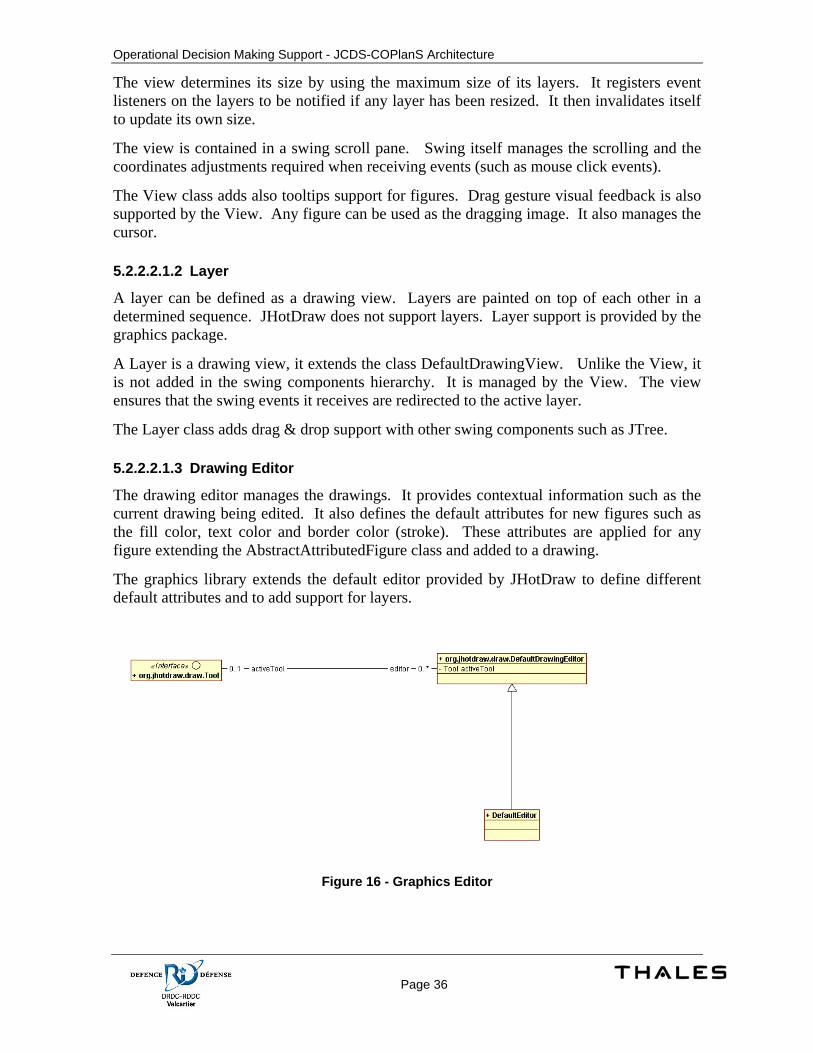
5.2.2.2.1.3 Drawing Editor
The drawing editor manages the drawings. It provides contextual information such as the current drawing being edited. It also defines the default attributes for new figures such as the fill color, text color and border color (stroke). These attributes are applied for any figure extending the AbstractAttributedFigure class and added to a drawing.
The graphics library extends the default editor provided by JHotDraw to define different default attributes and to add support for layers.
Figure 16 - Graphics Editor
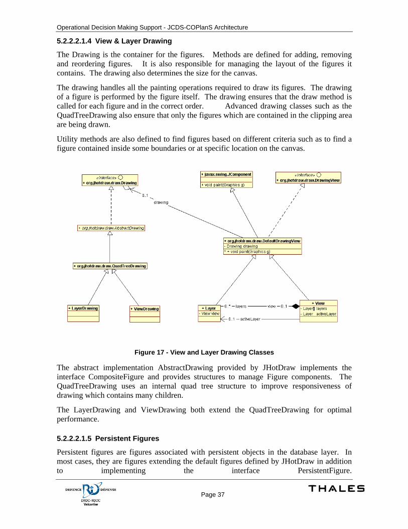
Operational Decision Making Support - JCDS-COPlanS Architecture
Page 37
5.2.2.2.1.4 View & Layer Drawing
The Drawing is the container for the figures. Methods are defined for adding, removing and reordering figures. It is also responsible for managing the layout of the figures it contains. The drawing also determines the size for the canvas.
The drawing handles all the painting operations required to draw its figures. The drawing of a figure is performed by the figure itself. The drawing ensures that the draw method is called for each figure and in the correct order. Advanced drawing classes such as the QuadTreeDrawing also ensure that only the figures which are contained in the clipping area are being drawn.
Utility methods are also defined to find figures based on different criteria such as to find a figure contained inside some boundaries or at specific location on the canvas.
Figure 17 - View and Layer Drawing Classes
The abstract implementation AbstractDrawing provided by JHotDraw implements the interface CompositeFigure and provides structures to manage Figure components. The QuadTreeDrawing uses an internal quad tree structure to improve responsiveness of drawing which contains many children.
The LayerDrawing and ViewDrawing both extend the QuadTreeDrawing for optimal performance.
5.2.2.2.1.5 Persistent Figures
Persistent figures are figures associated with persistent objects in the database layer. In most cases, they are figures extending the default figures defined by JHotDraw in addition to implementing the interface PersistentFigure.
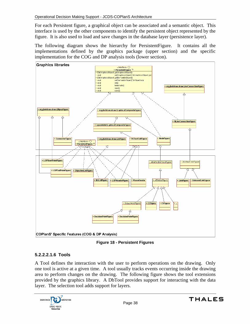
Operational Decision Making Support - JCDS-COPlanS Architecture
Page 38
For each Persistent figure, a graphical object can be associated and a semantic object. This interface is used by the other components to identify the persistent object represented by the figure. It is also used to load and save changes in the database layer (persistence layer).
The following diagram shows the hierarchy for PersistentFigure. It contains all the implementations defined by the graphics package (upper section) and the specific implementation for the COG and DP analysis tools (lower section).
Figure 18 - Persistent Figures
5.2.2.2.1.6 Tools
A Tool defines the interaction with the user to perform operations on the drawing. Only one tool is active at a given time. A tool usually tracks events occurring inside the drawing area to perform changes on the drawing. The following figure shows the tool extensions provided by the graphics library. A DbTool provides support for interacting with the data layer. The selection tool adds support for layers.
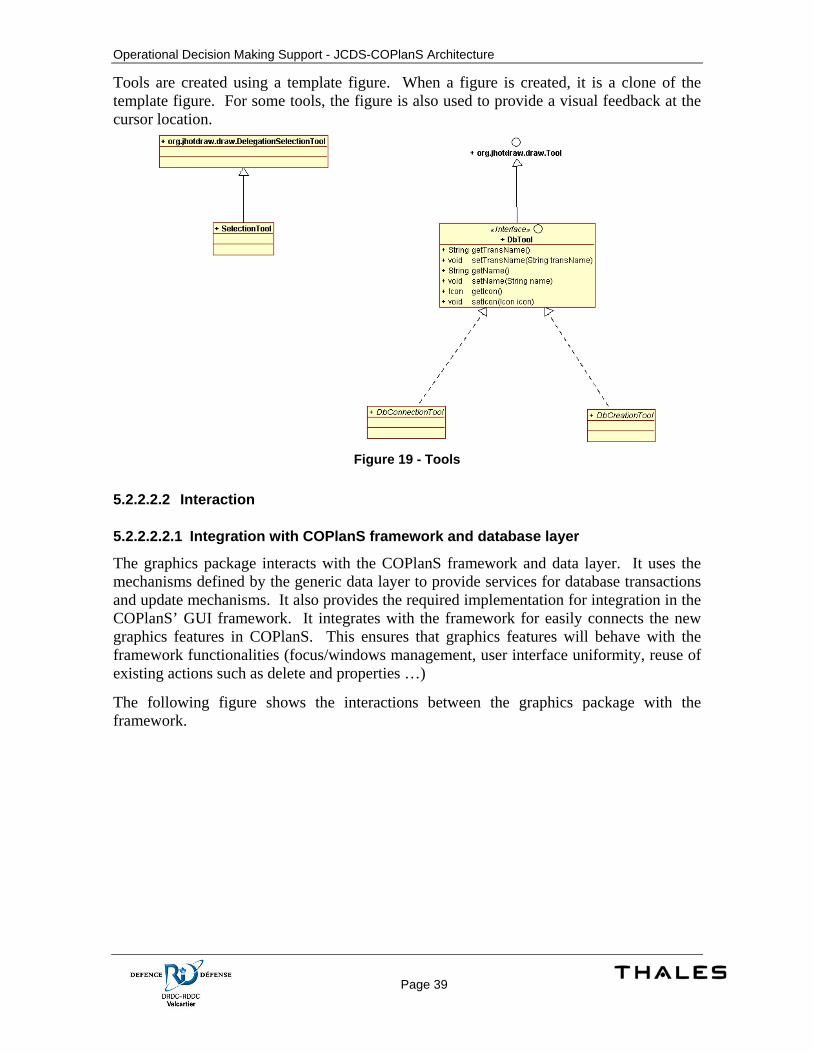
Operational Decision Making Support - JCDS-COPlanS Architecture
Page 39
Tools are created using a template figure. When a figure is created, it is a clone of the template figure. For some tools, the figure is also used to provide a visual feedback at the cursor location.
Figure 19 - Tools
5.2.2.2.2 Interaction
5.2.2.2.2.1 Integration with COPlanS framework and database layer
The graphics package interacts with the COPlanS framework and data layer. It uses the mechanisms defined by the generic data layer to provide services for database transactions and update mechanisms. It also provides the required implementation for integration in the COPlanS’ GUI framework. It integrates with the framework for easily connects the new graphics features in COPlanS. This ensures that graphics features will behave with the framework functionalities (focus/windows management, user interface uniformity, reuse of existing actions such as delete and properties …)
The following figure shows the interactions between the graphics package with the framework.
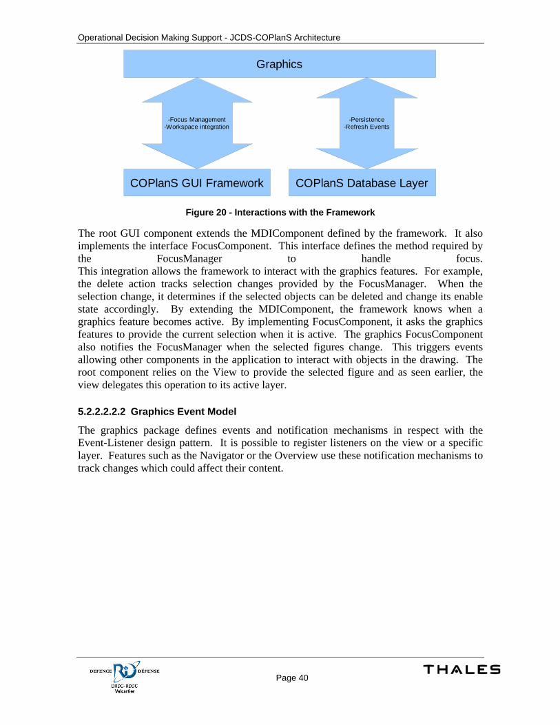
Operational Decision Making Support - JCDS-COPlanS Architecture
Page 40
COPlanS GUI Framework
Graphics
COPlanS Database Layer
-Focus Management-Workspace integration
-Persistence-Refresh Events
Figure 20 - Interactions with the Framework
The root GUI component extends the MDIComponent defined by the framework. It also implements the interface FocusComponent. This interface defines the method required by the FocusManager to handle focus. This integration allows the framework to interact with the graphics features. For example, the delete action tracks selection changes provided by the FocusManager. When the selection change, it determines if the selected objects can be deleted and change its enable state accordingly. By extending the MDIComponent, the framework knows when a graphics feature becomes active. By implementing FocusComponent, it asks the graphics features to provide the current selection when it is active. The graphics FocusComponent also notifies the FocusManager when the selected figures change. This triggers events allowing other components in the application to interact with objects in the drawing. The root component relies on the View to provide the selected figure and as seen earlier, the view delegates this operation to its active layer.
5.2.2.2.2.2 Graphics Event Model
The graphics package defines events and notification mechanisms in respect with the Event-Listener design pattern. It is possible to register listeners on the view or a specific layer. Features such as the Navigator or the Overview use these notification mechanisms to track changes which could affect their content.
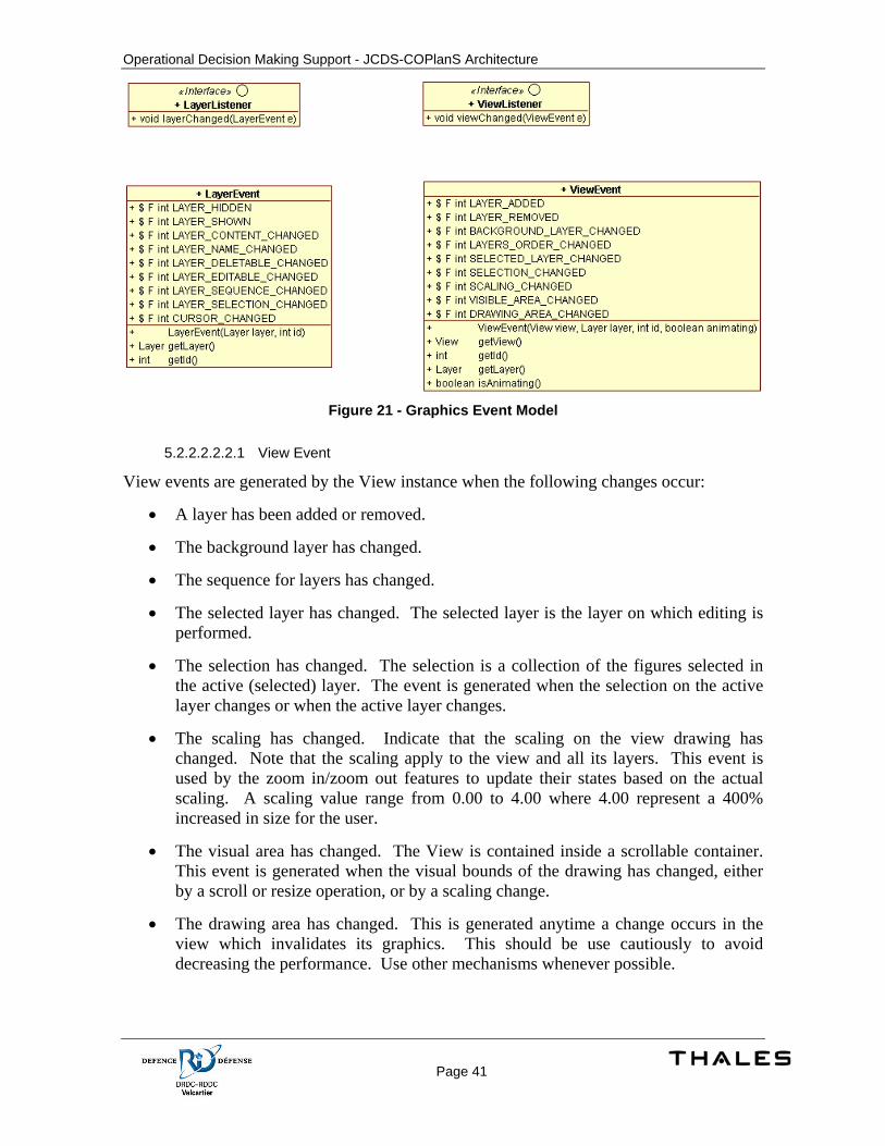
Operational Decision Making Support - JCDS-COPlanS Architecture
Page 41
Figure 21 - Graphics Event Model
5.2.2.2.2.2.1 View Event
View events are generated by the View instance when the following changes occur:
• A layer has been added or removed.
• The background layer has changed.
• The sequence for layers has changed.
• The selected layer has changed. The selected layer is the layer on which editing is performed.
• The selection has changed. The selection is a collection of the figures selected in the active (selected) layer. The event is generated when the selection on the active layer changes or when the active layer changes.
• The scaling has changed. Indicate that the scaling on the view drawing has changed. Note that the scaling apply to the view and all its layers. This event is used by the zoom in/zoom out features to update their states based on the actual scaling. A scaling value range from 0.00 to 4.00 where 4.00 represent a 400% increased in size for the user.
• The visual area has changed. The View is contained inside a scrollable container. This event is generated when the visual bounds of the drawing has changed, either by a scroll or resize operation, or by a scaling change.
• The drawing area has changed. This is generated anytime a change occurs in the view which invalidates its graphics. This should be use cautiously to avoid decreasing the performance. Use other mechanisms whenever possible.
Operational Decision Making Support - JCDS-COPlanS Architecture
Page 42
Components can register/unregister for this type of event by using the addViewEventListener() or removeViewEventListener() on the view object and by implementing the ViewListener interface.
The method isAnimating() can be used to check if an animation is currently active. This can be used to avoid performing x amount of update each time the animation is generating a change on the drawing (where x is the number of frame produced by the animation). When an animation complete, it is guaranteed that a drawing area change event is generated with isAnimating() returning false.
5.2.2.2.2.2.2 Layer Event
Layer events are generated by the Layer instances when the following changes occur:
• The layer has been hidden (layer visible property set to false)
• The layer has been shown (layer visible property set to true)
• The layer’s content has changed (a figure has been added or removed from the layer)
• The layer’s name has changed
• The layer’s deletable state has changed. The deletable state indicates if a layer can be deleted. A default layer for a diagram is usually not deletable to ensure at least one layer is available. Delete action on the layer should be disabled/enabled according to this property.
• The layer’s editable state has changed. When the layer’s editable state is set to false, no editing should be allowed on the layer. This is used by the Tools.
• The layer’s sequence has changed. Layers sequences are guaranteed to start from 0 (deepest layer) and increment by 1 for each subsequent layers. In some cases, such as during a layer load operation, the sequence number may be -1. Another event is generated when the sequence is set to its actual value.
• The selection inside the layer has changed. This is the same as receiving the ViewEvent notification if the active layer is the layer generating the LayerEvent. Tools should track View events instead to ensure they interact with the correct layer.
• The cursor has changed for the layer. This is used by the view to update the Swing/AWT cursor on the swing component based on the cursor of the active layer.
Components can register/unregister for this type of event by using the addLayerEventListener() or removeLayerEventListener() on the layer object and by implementing the LayerListener interface.

Operational Decision Making Support - JCDS-COPlanS Architecture
Page 43
5.2.2.2.2.3 Graphics Rendering
The following sequence diagram shows the sequence of operations for drawing the diagram. It shows the different layers composing the diagramming feature. The example used to trigger the paint is a move operation from the user. The same sequence is valid or very similar for any interaction with the drawing or changes on figures.
In the provided sequence, a user uses the selection tool to move a figure. The drag gesture event is first received by java. Java then determines on which Swing component the event applies and generates a MouseGestureEvent. The drawing editor register for receiving these events and in conjunction with the active Tool, it determines the operation to be performed on the drawing. In our example, the Selection Tool perform a move (translate) on the boundaries for the figure. The drawing view is then notified of the change by its figure. It then computes the invalidated area inside the swing component and notifies Swing that the area has been invalidated. Swing uses mechanisms to ensure that a repaint will eventually be done if an area is invalidated. Paint operations are done in another thread. When the tread managing the paint operations process the paint requests, it determines the clipping area to be painted. Any drawing performed outside the area is ignored for optimum performance.
The swing components marked as dirty are then painted by calling their paint method. The drawing view can use the provided Graphics object to render the drawing. This is done by painting the background then by calling the draw method on the drawing. The drawing object then determines which figures are contained inside the clipping bounds and call the draw() method on each figures.
It is important to understand the sequence of operation for the paint process to avoid conflicts and keep the drawing process as fast as possible. Paint operations may occur multiple times every second but are only performed when required.
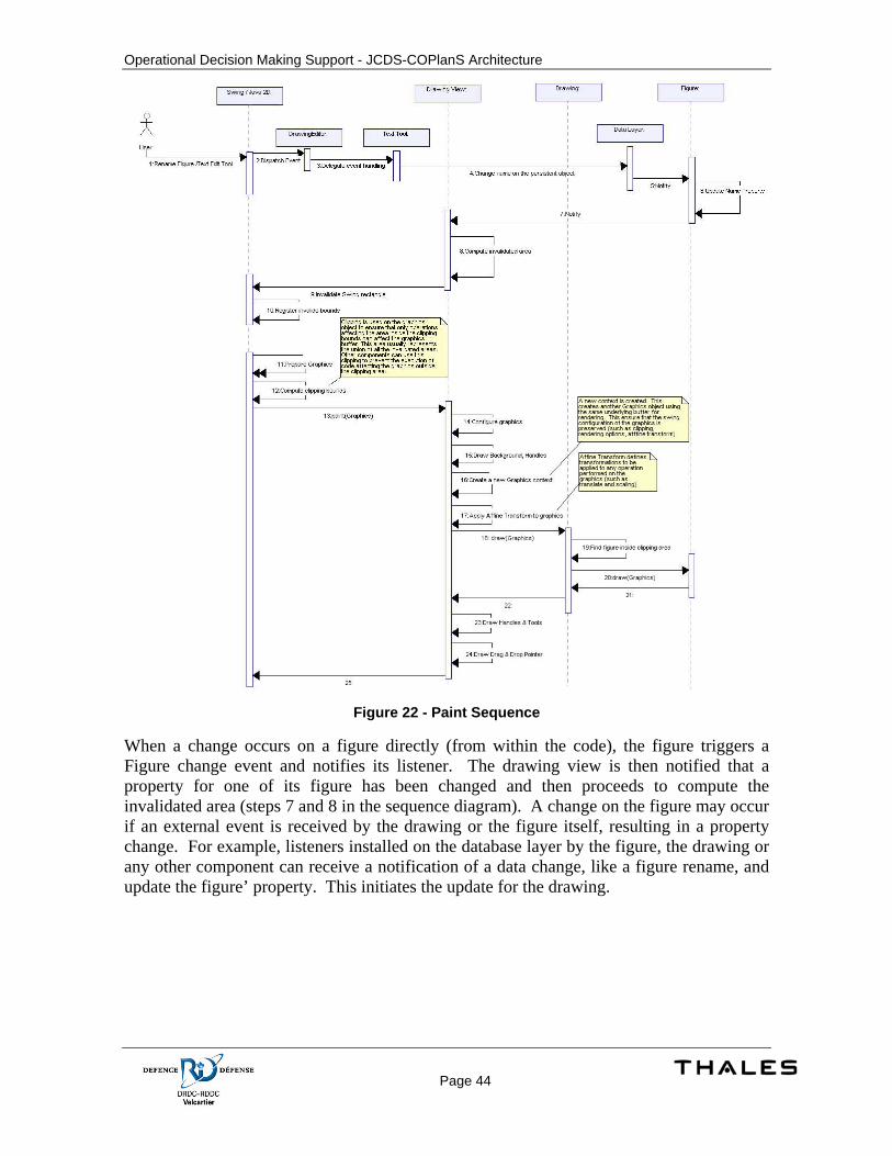
Operational Decision Making Support - JCDS-COPlanS Architecture
Page 44
Figure 22 - Paint Sequence
When a change occurs on a figure directly (from within the code), the figure triggers a Figure change event and notifies its listener. The drawing view is then notified that a property for one of its figure has been changed and then proceeds to compute the invalidated area (steps 7 and 8 in the sequence diagram). A change on the figure may occur if an external event is received by the drawing or the figure itself, resulting in a property change. For example, listeners installed on the database layer by the figure, the drawing or any other component can receive a notification of a data change, like a figure rename, and update the figure’ property. This initiates the update for the drawing.
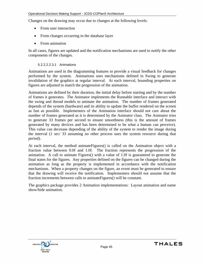
Operational Decision Making Support - JCDS-COPlanS Architecture
Page 45
Changes on the drawing may occur due to changes at the following levels:
• From user interaction
• From changes occurring in the database layer
• From animation
In all cases, figures are updated and the notification mechanisms are used to notify the other components of the changes.
5.2.2.2.2.3.1 Animations
Animations are used in the diagramming features to provide a visual feedback for changes performed by the system. Animations uses mechanisms defined in Swing to generate invalidation of the graphics at regular interval. At each interval, bounding properties on figures are adjusted to match the progression of the animation.
Animations are defined by their duration, the initial delay before starting and by the number of frames it generates. The Animator implements the Runnable interface and interact with the swing and thread models to animate the animation. The number of frames generated depends of the system (hardware) and its ability to update the buffer rendered on the screen as fast as possible. Implementers of the Animation interface should not care about the number of frames generated as it is determined by the Animator class. The Animator tries to generate 33 frames per second to ensure smoothness (this is the amount of frames generated by many devices and has been determined to be what a human can perceive). This value can decrease depending of the ability of the system to render the image during the interval (1 sec/ 33 assuming no other process uses the system resource during that period).
At each interval, the method animateFigures() is called on the Animation object with a fraction value between 0.0f and 1.0f. The fraction represents the progression of the animation. A call to animate Figures() with a value of 1.0f is guaranteed to generate the final states for the figures. Any properties defined on the figures can be changed during the animation as long as the property is implemented in accordance with the notification mechanisms. When a property changes on the figure, an event must be generated to ensure that the drawing will receive the notification. Implementers should not assume that the fraction increments between calls to animateFigures() will be constant.
The graphics package provides 2 Animation implementations: Layout animation and name show/hide animation.
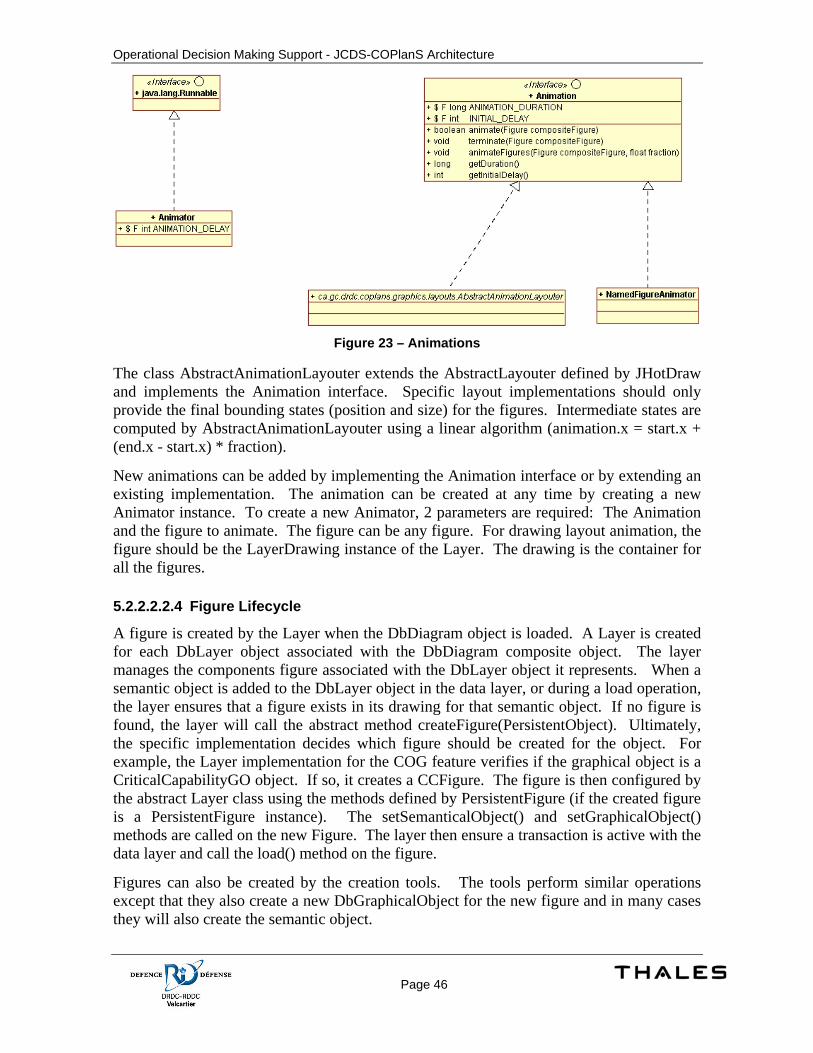
Operational Decision Making Support - JCDS-COPlanS Architecture
Page 46
Figure 23 – Animations
The class AbstractAnimationLayouter extends the AbstractLayouter defined by JHotDraw and implements the Animation interface. Specific layout implementations should only provide the final bounding states (position and size) for the figures. Intermediate states are computed by AbstractAnimationLayouter using a linear algorithm (animation.x = start.x + (end.x - start.x) * fraction).
New animations can be added by implementing the Animation interface or by extending an existing implementation. The animation can be created at any time by creating a new Animator instance. To create a new Animator, 2 parameters are required: The Animation and the figure to animate. The figure can be any figure. For drawing layout animation, the figure should be the LayerDrawing instance of the Layer. The drawing is the container for all the figures.
5.2.2.2.2.4 Figure Lifecycle
A figure is created by the Layer when the DbDiagram object is loaded. A Layer is created for each DbLayer object associated with the DbDiagram composite object. The layer manages the components figure associated with the DbLayer object it represents. When a semantic object is added to the DbLayer object in the data layer, or during a load operation, the layer ensures that a figure exists in its drawing for that semantic object. If no figure is found, the layer will call the abstract method createFigure(PersistentObject). Ultimately, the specific implementation decides which figure should be created for the object. For example, the Layer implementation for the COG feature verifies if the graphical object is a CriticalCapabilityGO object. If so, it creates a CCFigure. The figure is then configured by the abstract Layer class using the methods defined by PersistentFigure (if the created figure is a PersistentFigure instance). The setSemanticalObject() and setGraphicalObject() methods are called on the new Figure. The layer then ensure a transaction is active with the data layer and call the load() method on the figure.
Figures can also be created by the creation tools. The tools perform similar operations except that they also create a new DbGraphicalObject for the new figure and in many cases they will also create the semantic object.
Operational Decision Making Support - JCDS-COPlanS Architecture
Page 47
Drag & drop operations can also create new figure. Since they are often performed by dragging semantic objects, they usually only create DbGraphicalObject and the corresponding new figure.
During its lifetime, the figure’s properties can be changed but its parent drawing can’t change. A figure existence is bound to its association with its parent drawing. Breaking this link is the same as deleting the figure. This follows the Composite-Components design pattern.
A figure is deleted when the DbGraphicalObject it represents is deleted. The layer registers the listeners on the data layer to receive notification for add/delete operation on the diagram. When a DbGraphicalObject is removed, the layer search the figures contained in its drawing for a figure representing the DbGraphicalObject. If a figure is found, the layer call the setSemanticalObject() and setGraphicalObject() with null values to disconnect the figure from the persistent objects and to allow the figure to perform any clean up such as removing specific listeners. The figure is then removed from the drawing object.
A figure can also be deleted by the user by using the Delete action. As seen in a previous section, the Delete action is always aware of the selected figures on the drawing. When a delete is performed, the delete action ensures that a transaction is available on the data layer and then deletes the DbGraphicalObject or the semantic object. Deleting a semantic object systematically delete the associated graphical objects. Deleting a graphical object only removes the graphical object. Both are available and the choice to delete one or the other depends on the desired behaviour. Deleting the persistent object in the data layer eventually trigger, if successful, an event to indicate that the DbGraphicalObject and/or the semantic object have been deleted. The layer receives this event and proceeds as previously specified. Both cases are the same in that the layer performs the clean up operations when the data layer event is received. The first case may occurs when the delete is performed by another user on a different client.
The same also occurs when a DbGraphicalObject or its semantic object is removed as a cascading effect from a delete of their parent object. For the DbGraphicalObject, this would be a delete operation of the DbLayer object (which could also result from a delete on the layer’s parent, the diagram). Also note that removing the layer object will also terminate the drawing figure and the corresponding layer. Deleting the diagram object may result in the feature’s window to close if it can’t handle more than one diagram.
5.2.2.2.2.5 Data Changes
The graphics package uses mechanisms provided by the data layer to ensure its content always reflect the persistent states.
The interface PersistentFigure defines methods to add support for persistence. These methods are used by the graphics’s components to save and load states and properties for figures. They also provide the ability to register a figure to specific events provided by the database layer. When a figure is added on a drawing, the drawing ensures that the init() method is invoked to perform initialization. For registering listeners to the data layer, it is recommended to do so when the setSemanticObject and setGraphicalObject are invoked since these objects are usually not known during the call to init(). When a figure is removed, the terminate method is invoked.
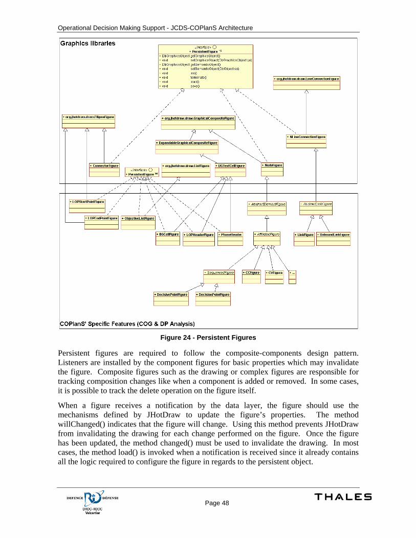
Operational Decision Making Support - JCDS-COPlanS Architecture
Page 48
Figure 24 - Persistent Figures
Persistent figures are required to follow the composite-components design pattern. Listeners are installed by the component figures for basic properties which may invalidate the figure. Composite figures such as the drawing or complex figures are responsible for tracking composition changes like when a component is added or removed. In some cases, it is possible to track the delete operation on the figure itself.
When a figure receives a notification by the data layer, the figure should use the mechanisms defined by JHotDraw to update the figure’s properties. The method willChanged() indicates that the figure will change. Using this method prevents JHotDraw from invalidating the drawing for each change performed on the figure. Once the figure has been updated, the method changed() must be used to invalidate the drawing. In most cases, the method load() is invoked when a notification is received since it already contains all the logic required to configure the figure in regards to the persistent object.
Operational Decision Making Support - JCDS-COPlanS Architecture
Page 49
A specialized figure, the NodeFigure, already provides most of the implementation for a PersistentFigure. This class defines a figure using any figure to determine its bounds. It contains a text zone for containing an ID and another optional text zone for the name. Inheriting figures should only provide the implementation for the load and save methods. Methods are provided for changing the visual aspect such as the stroke and fill colors. The class also provides a method (invalidateDrawingLayout) to trigger the necessary event to invalidate the drawing’s layout.
Other partial implementations are also provided for connection figures, background cell figures and list figures.
5.2.2.2.2.6 View, Editor, Tools & Handles
Tools are used by the users to perform operations on the drawing. There is only one tool active at a given time. The active tool is determined based on the action activated by the user (usually represented by a button on a toolbar). The active tool is provided by the Drawing Editor. When a tool is activated, it is set on the drawing editor managing the active view as being the active tool. It is available from the view but it is important to note that the editor is not exclusive to that view. An editor can manage many views. For example, a single toolbar can be used to interact with more than one view. This is possible because the editing logic is separated from the view itself and because the editor is designed with the capability to switch its context’s view.
The specialized Action class has been added for managing the interaction with a tool. This action configures its visual properties as defined by the tool it manages. When an action is activated (usually by using by pressing the button on the toolbar), the action determines which editor is managing the active view and set the tool on the editor.
The editor then ensures that if a tool was already active, it is deactivated. When a tool is deactivated, it reset all its internal states. This is a reset of the tool. It is important to note that many tools are performed using more than one step (or event). For example, the area selection tool first check for a mouse pressed event on the view. When this event occurs, it stores the mouse pressed location (the x and y coordinates) in its state. Once this initial point is set, it then tracks for mouse drag event to determine the selected area. When it completes, it determines the figures contained inside the rectangle representing the selection area and notify the active layer that these figures are now the new selection. If the tool sequence of events is aborted at any time, it resets its states. This is done by the tool when its deactivate() method is invoked by the editor.
When the active view changes, the editor deactivates the active tool. It removes any listener on the previous active view. Then it installs the listeners for the new active view. Listeners installed are mouse listener, mouse motion listener and key listener. The editor delegates the events it receives from the view to the active tool. The tool then determines if the event is valid and what it should do with it.
Tools often need to compute the event location relative to a figure in order to decide what they should do. For example, a resize operation should only be possible when the mouse press event occurs inside small rectangle areas on each corner of the figure, allowing a move operation to be performed if the mouse press event is occurring outside these areas.
Operational Decision Making Support - JCDS-COPlanS Architecture
Page 50
On another level, a figure is often required to provide a visual feedback on the areas the user can uses to interact. Handles are used to solve both requirements. Handles are created by the figures in order to determine how the tools can interact with them. Handles also provide a visual feedback when a figure is selected. The rendering of the handle is done by the handles themselves but is managed by the drawing. The draw() method on the handles is invoked by the drawing after all other draw operation are completed to ensure the handles are always visible (regardless of what the figure sequence is).
When a tool receives an event, it asks the active view to find the figure at the event coordinate. The tool then asks the figure to provide the handle to use for the location. The tool can also interact without consideration for handles. This is often the case for creation tools for node type figures. In JHotDraw, the handles are used by the SelectionTool to delegate the operation to a specialized tool such as the SelectAreaTool or DragTool (for move and resize operations). Handles give flexibility on for interacting with the drawing in addition to allow reuse of visual representations.
5.2.2.2.3 User Interface’s Components
User components provided with the graphics packages are covered in this section.
5.2.2.2.3.1 Overview
The overview installs a view listener and mouse listeners on the view. It tracks changes on the drawings to provide a different view of the drawings. The drawing is rendered using the same mechanisms used by the view component itself but does not draw the handles. A clipping is applied on the graphics object based on the mouse pointer location, the visible area of the drawing (based on the scrollable visible area) and the scaling used. The image is updated when the mouse cursor is moved or when the content of a layer drawing has changed. This feature does not provide direct interactions with the user.
The Overview configures the Java2D graphics object with a scaling of 1.1 for rendering the drawing, ignoring the scaling specified on the view.
5.2.2.2.3.2 Navigator
The navigator interacts with the View to control the visual area and the zoom factor (scaling). A view listener is registered on the View to track changes on the drawing and on the scaling.
When a scaling tool is activated on the navigator (zoom in, zoom out, manual zoom text field or zoom slider), the navigator invokes the setScalingFactor() method on the View. The view then notify Swings that it needs a repaint() and notify its container (the ScrollPane) that its size has changed. Scaling is handled by using mechanisms in Java2D. These mechanisms allow the use of an AffineTransform to apply changes on any basic operation performed on a Java2D graphics object. An affine transform can specify a scaling. The view changes the scaling by applying an affine transform on the Java 2D graphics object during the rendering operation.
When the visible area selection tool is changed, the navigator asks the view to change its visible area. The view then notifies its container of this change.

Operational Decision Making Support - JCDS-COPlanS Architecture
Page 51
The visible area is ultimately managed by the scrollable panel containing the View. Changing the visible area on the Swings’ scrollable panel component triggers a repaint().
When the scaling factor or visible area changes on the View, the view triggers a ViewEvent to notify its view listeners. The Navigator listens to these events and updates its components accordingly. This is done even if the navigator is the component that initially changed the visible area or the scaling factor. This ensures that it is always synchronized with the View, regardless of what is the source of the change.
5.2.2.2.3.3 Layers management tool
The layers management tool interacts with the View to provide add, remove, show, hide, ordering and rename layer support.
Listeners are installed on the View for tracking changes. When a new layer is added, a new component is added to manage this layer. The component is removed when the View generate an event to notify that a layer has been removed. This component installs its own listeners on the layer it manages.
Actions are added to a toolbar contained in this feature. When the insert layer action is activated, it initiate a transaction with the data layer then asks the DbDiagram object managed by the view to create a new DbLayer object. It also ensures that the sequences for layers is valid and insert the layer at the correct position. Through the data layer notification mechanisms, the view is then notified that a new layer has been added and creates the Layer object for handling the new layer. It also triggers a View Event. This event is received by the layers management tool which creates a component to represent the layer and provides the mechanisms to show/hide, rename and reorder the layer.
The same sequence of execution also applies for a delete operation on a layer.
The GUI component created for managing a layer shows a small preview image of the layer’s drawing. It draws the preview by applying an AffineTransform on the Java2D graphics object. The scaling applied on the affine transform is computed to fit in the preview area. The draw() method is then called on the Layer object. Note that the graphics configuration, such as scaling, is usually performed by the View itself before the rendering of each layer. Since the coordinate system used by the drawing is fixed regardless of any transform, it is easy to reuse the draw mechanisms defined by the drawing component.
When a layer is hidden or shown, the tool changes the property on the layer. This trigger an event on the layer and the view is notified that its content has been invalidated and need a repaint. This also applies when a layer is reordered. Only the event IDs generated by the layer differ.
5.2.2.2.3.4 Explorer
The Explorer extends the Explorer component provided by the COPlanS’s GUI framework. This component automatically installs listeners and tracks changes in the data layer. It also provides automatic creation of nodes using meta information. Specific features should only specify the root object and which associations to expand for each type of object it can contains.
Operational Decision Making Support - JCDS-COPlanS Architecture
Page 52
5.2.2.2.4 Data Requirements
In order to use the graphics package, it is required by the application’s model to implements and extends components defined by the data layer framework.
Model classes are required to extends the class DbObject and specify the Meta information. The DbObject class (along with its package) contains the mechanisms for event notifications and persistence support. Meta information provides generic mechanisms to specify properties and behaviours for model components. This allows the abstraction of the model specific concepts when building generic functionalities. For example, the graphics package tracks the objects added to a COG analysis layer without knowing the concrete class representing the layer object or its components objects. This is possible because the Meta information contains this information. The definition of the schema is known by the generic feature. In the example, the meta information for the class COG Analysis Layer specifies which associations define the components for this class. When the Layer class for the COG analysis feature is loading its content, it checks on the Meta information to determine what it should ask to the data layer to retrieve the layer’s components.
The data layer’s services are used extensively by the graphics package to provide a reusable generic framework for diagramming features. This allows a faster development process, minimizes the required code and provides reusable components. The data layer specific designs are not covered by this document.
The data layer defines a set of interfaces for defining graphics components in the model.
5.2.2.2.4.1 Persistence layer extensions
One of the main goals of the graphics package is the ability to handle persistence without the need for each of the specific features such as the COG analysis to manage this. In order to support this, interfaces have been added to the persistence layer. This allows abstraction of the COPlanS specific model for the graphics package. Specific classes for COPlanS implement these interfaces.
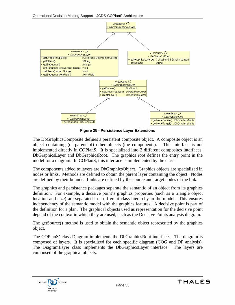
Operational Decision Making Support - JCDS-COPlanS Architecture
Page 53
Figure 25 - Persistence Layer Extensions
The DbGraphicsComposite defines a persistent composite object. A composite object is an object containing (or parent of) other objects (the components). This interface is not implemented directly in COPlanS. It is specialized into 2 different composites interfaces: DbGraphicsLayer and DbGraphicsRoot. The graphics root defines the entry point in the model for a diagram. In COPlanS, this interface is implemented by the class
The components added to layers are DbGraphicsObject. Graphics objects are specialized in nodes or links. Methods are defined to obtain the parent layer containing the object. Nodes are defined by their bounds. Links are defined by the source and target nodes of the link.
The graphics and persistence packages separate the semantic of an object from its graphics definition. For example, a decisive point’s graphics properties (such as a triangle object location and size) are separated in a different class hierarchy in the model. This ensures independency of the semantic model with the graphics features. A decisive point is part of the definition for a plan. The graphical objects used as representation for the decisive point depend of the context in which they are used, such as the Decisive Points analysis diagram.
The getSource() method is used to obtain the semantic object represented by the graphics object.
The COPlanS’ class Diagram implements the DbGraphicsRoot interface. The diagram is composed of layers. It is specialized for each specific diagram (COG and DP analysis). The DiagramLayer class implements the DbGraphicsLayer interface. The layers are composed of the graphical objects.
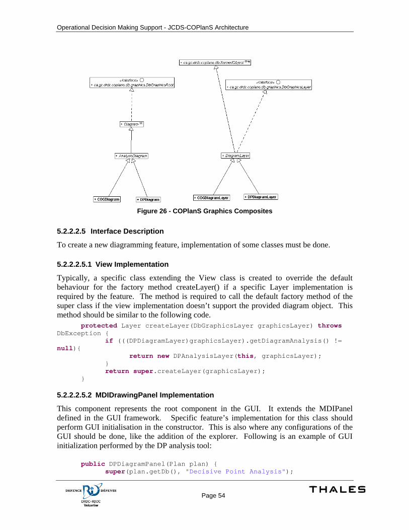
Operational Decision Making Support - JCDS-COPlanS Architecture
Page 54
Figure 26 - COPlanS Graphics Composites
5.2.2.2.5 Interface Description
To create a new diagramming feature, implementation of some classes must be done.
5.2.2.2.5.1 View Implementation
Typically, a specific class extending the View class is created to override the default behaviour for the factory method createLayer() if a specific Layer implementation is required by the feature. The method is required to call the default factory method of the super class if the view implementation doesn’t support the provided diagram object. This method should be similar to the following code. protected Layer createLayer(DbGraphicsLayer graphicsLayer) throws DbException { if (((DPDiagramLayer)graphicsLayer).getDiagramAnalysis() != null){ return new DPAnalysisLayer(this, graphicsLayer); } return super.createLayer(graphicsLayer); }
5.2.2.2.5.2 MDIDrawingPanel Implementation
This component represents the root component in the GUI. It extends the MDIPanel defined in the GUI framework. Specific feature’s implementation for this class should perform GUI initialisation in the constructor. This is also where any configurations of the GUI should be done, like the addition of the explorer. Following is an example of GUI initialization performed by the DP analysis tool:
public DPDiagramPanel(Plan plan) { super(plan.getDb(), "Decisive Point Analysis");
Operational Decision Making Support - JCDS-COPlanS Architecture
Page 55
this.plan = plan; initToolBars(); explorerTools = new FeatureContainer("Analysis Explorer & Tools"); DPToolsFeaturePanel tools = new DPToolsFeaturePanel(this); JSplitPane contentPane = new JSplitPane(JSplitPane.VERTICAL_SPLIT, new DPExplorerFeaturePanel(this), tools); contentPane.setDividerLocation(0.5); contentPane.setResizeWeight(0.5); contentPane.setOneTouchExpandable(false); explorerTools.setContentPane(contentPane); getFeaturesContainer().addFeature(explorerTools, 0); try { explorerTools.setCollapsed(true); } catch (PropertyVetoException e1) { } }
It is also required to override the factory method createView() if a specific View component is required by the feature. protected View createView() { return new DPView(getEditor()); }
In this example, the getEditor() method is used to obtain the default Editor created by the graphics package.
It is also possible to override other factory methods such as createNavigator(), createToolbar(), createMagnifier() or createGraphicsFactory(). In most cases, the default graphics factory defined by the graphics package can be used. This factory is used to configure the Java2D graphics object before performing a rendering of the drawing. The default factory uses a balanced configuration between rendering quality and performance. Drawing features can provide a different configuration such as disabling anti-aliasing if performance becomes an issue.
5.2.2.2.5.3 Layer Implementation
Layout is the most important component because it defines the drawing contents for a specific diagram. It also defines factory methods to create the figures and how drag & drop operation are performed.
During its initialization, a layer should be configured. Methods are available to set properties such as editable and to specify if drag&drop operations are supported by the layer. The following example shows the initialization for the COG Analysis layer implementation: public COGAnalysisLayer(View view, DbGraphicsLayer graphicsLayer) { super(view, graphicsLayer); setEditable(true);
Operational Decision Making Support - JCDS-COPlanS Architecture
Page 56
getDrawing().setLayouter(new COGLayouter(this)); namedFigureAnimator = new NamedFigureAnimator(getDrawing()); setEmptyDrawingMessage("No Analysis Items."); addZones(); setDndEnabled(true); }
In this example, the editable property is set to true to indicate that tools can interact with the drawing managed by this layer. The drawing is also configured with a specific layouter. An animator is defined for supporting animation of the transition when the names of the figures are set to visible or hidden. Drag & Drop operations are also enabled and the background figures are created by the addZones() method. These figures are fixed and not dependant of any persistent states, they are created once and thus added on the drawing when the layer is created. Other initialization such as the creation of figures according to persistent objects are handled later using the load method.
The load method must be overridden to load figures from the data layer. It is strongly recommended to always call super.load() to ensure the super class can load the information it needs. The following shows the operations performed by the load method for the analysis layer of the COG feature. Note that in most cases the load process is handled by the graphics package. A call to loadGraphicsObjects() with the Meta information representing the contents to load from the DbGraphisRoot (the diagram) object will automatically expands associated objects, manage the creation of the corresponding figures and install the listeners required in order to receive a notification when an object is added or removed from this association. The handling of these notifications and the removal of the listeners are also provided by the Layer class. public void load() throws DbException { super.load(); loadGraphicsObjects(COGDiagramLayer.fCenterOfGravityGOs); loadGraphicsObjects(COGDiagramLayer.fCriticalCapabilityGOs); loadGraphicsObjects(COGDiagramLayer.fCriticalRequirementGOs); loadGraphicsObjects(COGDiagramLayer.fCriticalVulnerabilityGOs); loadGraphicsObjects(COGDiagramLayer.fDecisivePointGOs); loadGraphicsObjects(COGDiagramLayer.fLinkGOs); }
The init() and terminate() methods should be overridden to install and remove listeners. Sub classes are required to call super.init() and super.terminate().
For supporting cases not covered by the Layer class, it is possible to load specific contents and use the basicAddFigure methods to populate the drawing. It is possible to mix the automated mechanisms along the customized methods. It is important to keep in mind that figures added directly may not be tracked automatically for changes and thus sub classes using these mechanisms should ensure they also provide this support. The DP analysis layer implementation uses a mix of both approaches. It is also possible to use the basicAddFigure by providing the persistent object. In this case, the Layer class uses the same process as for loadGraphicsObjects to create the corresponding figure and insert the figure in the drawing. In all cases, the initialisation and terminate methods on the PersistentFigure are managed by the Layer class.
Operational Decision Making Support - JCDS-COPlanS Architecture
Page 57
To perform additional operations when a figure is added, it is possible to override the figureLoaded() method. This can also be used to invalidate various states or other figures bounded to specific figures (for example a figure which resize depending of other figures in a specific area).
The factory method createFigure() must be provided. This method must determine and create the correct figure for representing a persistent object. The following code shows how this is implemented for the COG analysis feature: protected Figure createFigure(PersistentObject po) throws DbException { Figure figure = null; if (po instanceof LinkGO) { figure = new LinkFigure(); } else if (po instanceof CriticalVulnerabilityGO) { figure = new CVFigure(); } else if (po instanceof CriticalCapabilityGO) { figure = new CCFigure(); } else if (po instanceof CriticalRequirementGO) { figure = new CRFigure(); } else if (po instanceof COGDecisivePointGO) { figure = new DPFigure(); } else if (po instanceof COGCenterOfGravityGO) { figure = new COGFigure(AffiliatedElementFigure.ElementAffiliation.UNSPECIFIED); } if (figure != null) return figure; return super.createFigure(po); }
This method is called any time a load operation is performed, either from an initial load operation or from a notification received by the data layer.
If the layer supports drag & drop operations, it must override the methods initPersistentObjectDrop(), acceptPersistentObjectDrop() and dropPersistentObject(). public void initPersistentObjectDrop(Object object, Point2D.Double point) { if (object instanceof NamedObject) { try { COGDiagramLayer layer = (COGDiagramLayer) getGraphicsLayer(); Db db = layer.getDb(); db.beginReadTransaction(); dragName = ((NamedObject) object).getName(); db.commitTransaction(); } catch (Exception e) { ExceptionHandler.handleException(e); } } }
In this example, the COG analysis layer check if the object being dragged is a NamedObject (NamedObject is the super class for all persistent classes in the model that support a name property).
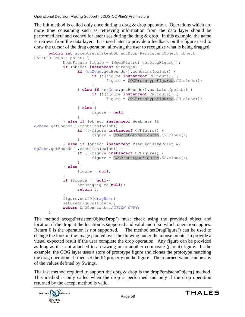
Operational Decision Making Support - JCDS-COPlanS Architecture
Page 58
The init method is called only once during a drag & drop operation. Operations which are more time consuming such as retrieving information from the data layer should be performed here and cached for later uses during the drag & drop. In this example, the name is retrieve from the data layer. It is used later to provide a feedback on the figure used to draw the cursor of the drag operation, allowing the user to recognize what is being dragged. public int acceptPersistentObjectDrop(PersistentObject object, Point2D.Double point) { NodeFigure figure = (NodeFigure) getDragFigure(); if (object instanceof Strength) { if (ccZone.getBounds().contains(point)) { if (!(figure instanceof CCFigure)) { figure = COGPrototypeFigures.CC.clone(); } } else if (crZone.getBounds().contains(point)) { if (!(figure instanceof CRFigure)) { figure = COGPrototypeFigures.CR.clone(); } } else { figure = null; } } else if (object instanceof Weakness && cvZone.getBounds().contains(point)) { if (!(figure instanceof CVFigure)) { figure = COGPrototypeFigures.CV.clone(); } } else if (object instanceof PlanDecisivePoint && dpZone.getBounds().contains(point)) { if (!(figure instanceof DPFigure)) { figure = COGPrototypeFigures.DP.clone(); } } else { figure = null; } if (figure == null){ setDragFigure(null); return 0; } figure.setID(dragName); setDragFigure(figure); return DnDConstants.ACTION_COPY; }
The method acceptPersistentObjectDrop() must check using the provided object and location if the drop at the location is supported and valid and if so which operation applies. Return 0 is the operation is not supported. The method setDragFigure() can be used to change the look of the image painted over the drawing under the mouse pointer to provide a visual expected result if the user complete the drop operation. Any figure can be provided as long as it is not attached to a drawing or to another composite (parent) figure. In the example, the COG layer uses a store of prototype figure and clones the prototype matching the drag operation. It then set the ID property on the figure. The returned value can be any of the values defined by Swings.
The last method required to support the drag & drop is the dropPersistentObject() method. This method is only called when the drop is performed and only if the drop operation returned by the accept method is valid.
Operational Decision Making Support - JCDS-COPlanS Architecture
Page 59
5.2.2.2.5.4 Layout Implementation
Animated or normal layouter can be specified on the layer’s drawing. The layout is invalidated each time a bounding property for a figure contained in the drawing is changed (such as the size and the location). When a layout is invalidated, a call to the layout() method is performed. Note that this may not occurs for each change to a property but it is guaranteed to be called at least once after a change to a property. This means that there can be only one call to layout() following a group of changes. This behaviour is used for performance reason and to avoid unnecessary computing of the layout. The guaranty is only valid if changes on figures are done in respect with JHotDraw mechanism. It is strongly recommended to perform bounding property changes by using the willChange() and changed() methods.
For animated layout, the layout() method can’t be overridden. To compute the layout, sub classes must instead compute the final states of the animation by implementing the method computeEndBounds(). It is also possible to override the initial states. The default implementation uses the current figures’ bounds as the initial state for the animation.
5.2.2.2.5.5 Tools
Tools performing changes on figure that must be persisted are required to implement the following methods and to specify a name for the tool and a transaction name. These names are respectively used by to identify the tool in the toolbar and to identify the change when the changes are committed (used for undo-redo identification).
The createDbObject() method must create a DbGraphicalObject. The created figure is provided and the DbGraphicsLayer that should be used for the composite is also provided. This method must also create a corresponding semantic object if required by the model design. In some cases, the graphical object is created and then linked with an existing semantic object. This method must also bind the created figure with the new DbGraphicalObject and semantic object by using the setSemanticObject() and setGraphicalObject() methods on the figure.
5.2.2.2.5.6 Figures
Figures should be added according to the needs of the diagram. Link figures should extendDbConnectionFigure to ensure support for persistence. NodeFigure should be used for most other figures representing a persistent object.
5.2.2.3 Centre of Gravity Detailed Design The center of gravity analysis display is a tool, located in the orientation stage, to create and visualize links between COGs, CCs, CRs, CVs and DPs. The Orientation stage will contain an action to open the COG analysis display. The tool manages analysis items related to the own and adversary affiliations.
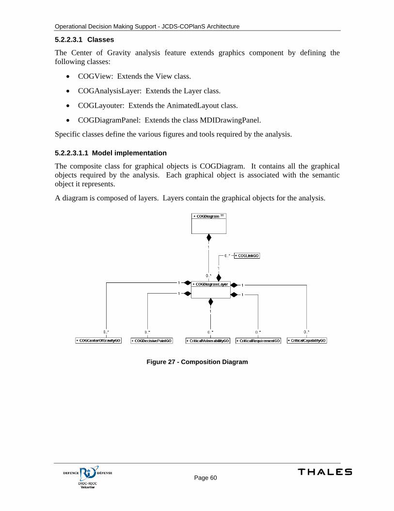
Operational Decision Making Support - JCDS-COPlanS Architecture
Page 60
5.2.2.3.1 Classes
The Center of Gravity analysis feature extends graphics component by defining the following classes:
• COGView: Extends the View class.
• COGAnalysisLayer: Extends the Layer class.
• COGLayouter: Extends the AnimatedLayout class.
• COGDiagramPanel: Extends the class MDIDrawingPanel.
Specific classes define the various figures and tools required by the analysis.
5.2.2.3.1.1 Model implementation
The composite class for graphical objects is COGDiagram. It contains all the graphical objects required by the analysis. Each graphical object is associated with the semantic object it represents.
A diagram is composed of layers. Layers contain the graphical objects for the analysis.
Figure 27 - Composition Diagram
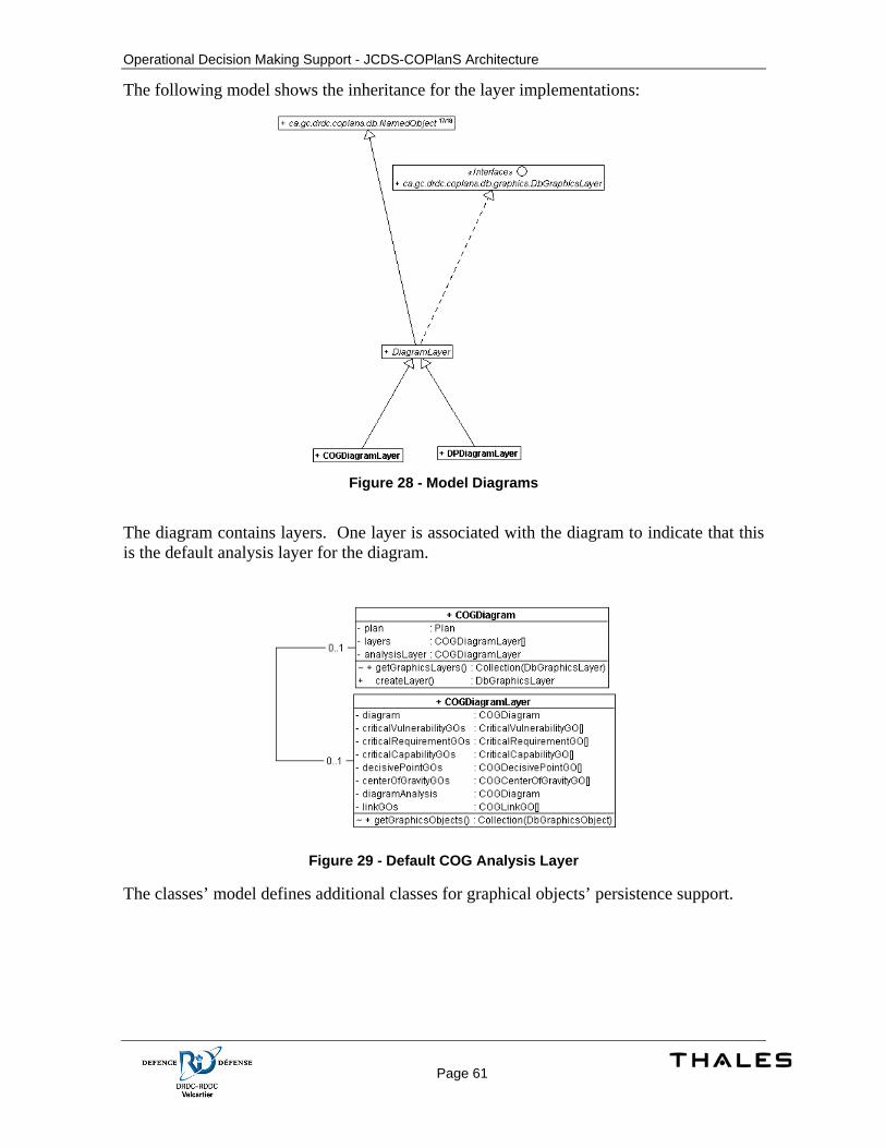
Operational Decision Making Support - JCDS-COPlanS Architecture
Page 61
The following model shows the inheritance for the layer implementations:
Figure 28 - Model Diagrams
The diagram contains layers. One layer is associated with the diagram to indicate that this is the default analysis layer for the diagram.
Figure 29 - Default COG Analysis Layer
The classes’ model defines additional classes for graphical objects’ persistence support.
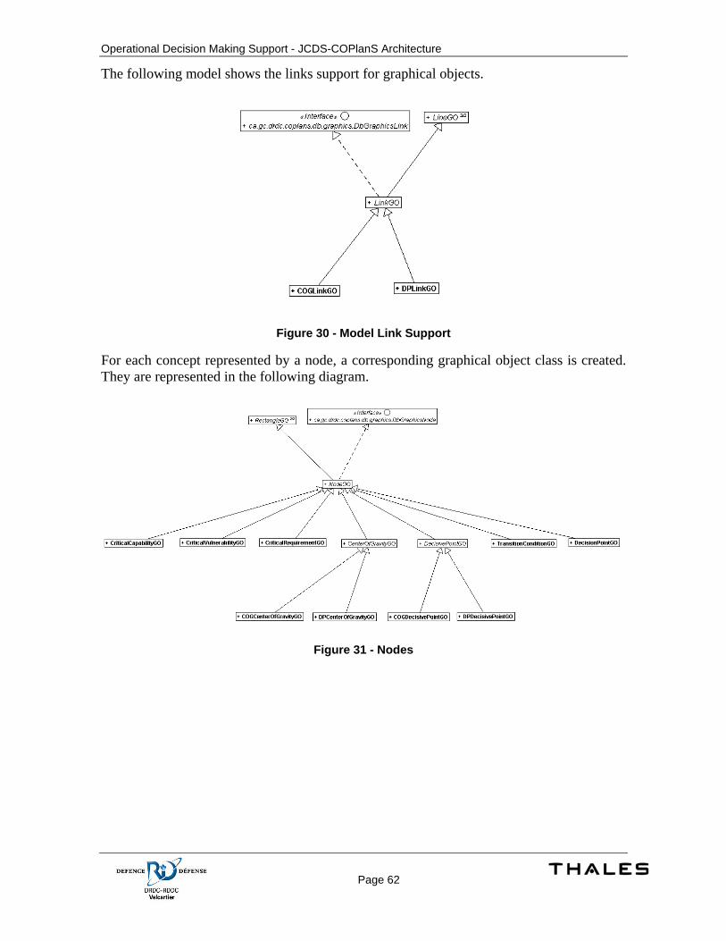
Operational Decision Making Support - JCDS-COPlanS Architecture
Page 62
The following model shows the links support for graphical objects.
Figure 30 - Model Link Support
For each concept represented by a node, a corresponding graphical object class is created. They are represented in the following diagram.
Figure 31 - Nodes
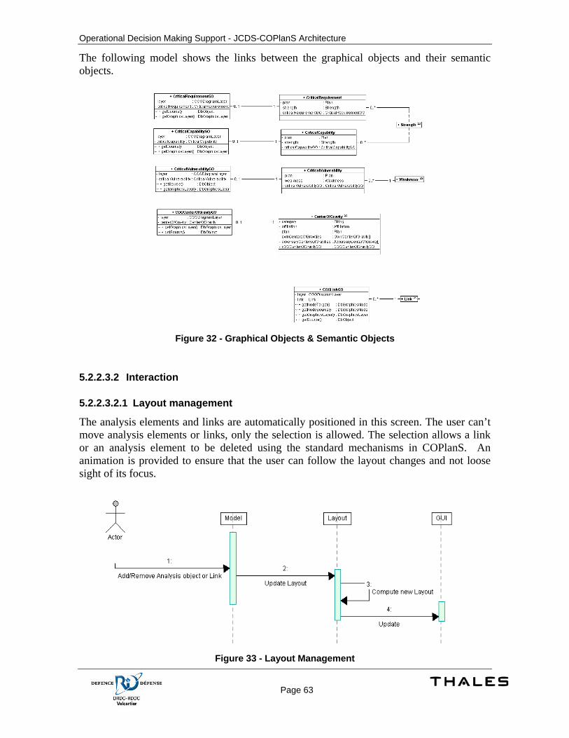
Operational Decision Making Support - JCDS-COPlanS Architecture
Page 63
The following model shows the links between the graphical objects and their semantic objects.
Figure 32 - Graphical Objects & Semantic Objects
5.2.2.3.2 Interaction
5.2.2.3.2.1 Layout management
The analysis elements and links are automatically positioned in this screen. The user can’t move analysis elements or links, only the selection is allowed. The selection allows a link or an analysis element to be deleted using the standard mechanisms in COPlanS. An animation is provided to ensure that the user can follow the layout changes and not loose sight of its focus.
Figure 33 - Layout Management
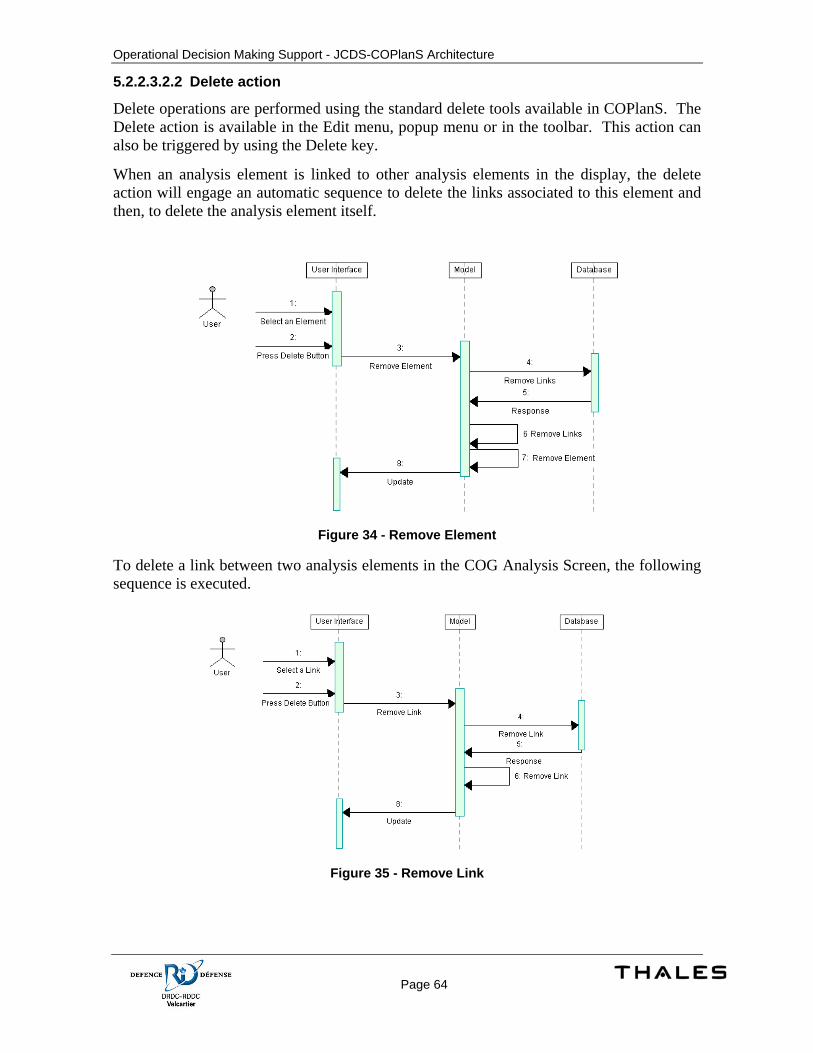
Operational Decision Making Support - JCDS-COPlanS Architecture
Page 64
5.2.2.3.2.2 Delete action
Delete operations are performed using the standard delete tools available in COPlanS. The Delete action is available in the Edit menu, popup menu or in the toolbar. This action can also be triggered by using the Delete key.
When an analysis element is linked to other analysis elements in the display, the delete action will engage an automatic sequence to delete the links associated to this element and then, to delete the analysis element itself.
Figure 34 - Remove Element
To delete a link between two analysis elements in the COG Analysis Screen, the following sequence is executed.
Figure 35 - Remove Link
Operational Decision Making Support - JCDS-COPlanS Architecture
Page 65
5.2.2.3.3 User Interface
5.2.2.3.3.1 Center of Gravity Analysis Screen
This screen’s main goal is to manage and visualize links between elements. This screen will allow the user to create new analysis objects and to link existing analysis objects. The unlink feature for this screen is provided by using the COPlanS delete action. The screen will manage links between specifics objects and ensure that invalid operations are not possible.
Object types managed by the screen are:
• COGs (Center of gravity)
• CCs (Critical Capability)
• CRs (Critical Requirement)
• CVs (Critical Vulnerability)
• DPs (Decisive Point) These objects can be linked to each other. The authorized associations are the following:
• COG to CC
• CC to CR
• CR to CV
• CV to DP
The COG Analysis tool leverage the links management feature by using the generic Link to manage these links.
The Center of Gravity analysis tool is built on the COPlanS framework. Any operations performed on Analysis Elements and Links benefit from the frameworks features (such as undo – redo operations).
For most objects part of the COG analysis (CC, CR and CV), they are used to represent their role related to the COG analysis. But these objects represent Strengths (for CC and CR) and Weaknesses (CV). When manipulating the objects in the diagram, this relation between the analysis element and its semantic object is transparent. When adding items using the tools, a semantic object is also created by the system. On delete operations, the semantic objects are preserved since they can be used for other purposes. When using the tree view for creating objects (from drag & drop), only the COG analysis object is created and it is associated with the dragged semantic object by the tool.
The following figure shows the Center of Gravity Analysis Screen. The screen is divided in 4 distinct sections: the drawing area, the toolbar, the analysis explorer pane and the navigation & magnifier pane.
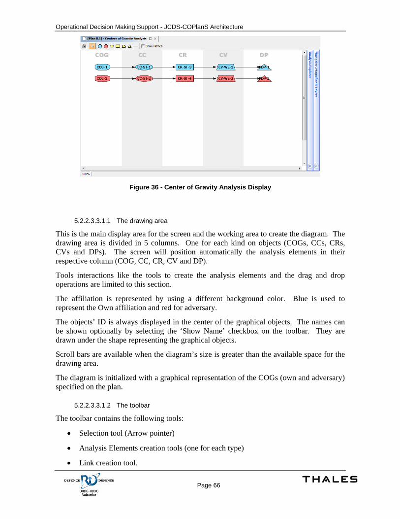
Operational Decision Making Support - JCDS-COPlanS Architecture
Page 66
Figure 36 - Center of Gravity Analysis Display
5.2.2.3.3.1.1 The drawing area
This is the main display area for the screen and the working area to create the diagram. The drawing area is divided in 5 columns. One for each kind on objects (COGs, CCs, CRs, CVs and DPs). The screen will position automatically the analysis elements in their respective column (COG, CC, CR, CV and DP).
Tools interactions like the tools to create the analysis elements and the drag and drop operations are limited to this section.
The affiliation is represented by using a different background color. Blue is used to represent the Own affiliation and red for adversary.
The objects’ ID is always displayed in the center of the graphical objects. The names can be shown optionally by selecting the ‘Show Name’ checkbox on the toolbar. They are drawn under the shape representing the graphical objects.
Scroll bars are available when the diagram’s size is greater than the available space for the drawing area.
The diagram is initialized with a graphical representation of the COGs (own and adversary) specified on the plan.
5.2.2.3.3.1.2 The toolbar
The toolbar contains the following tools:
• Selection tool (Arrow pointer)
• Analysis Elements creation tools (one for each type)
• Link creation tool.
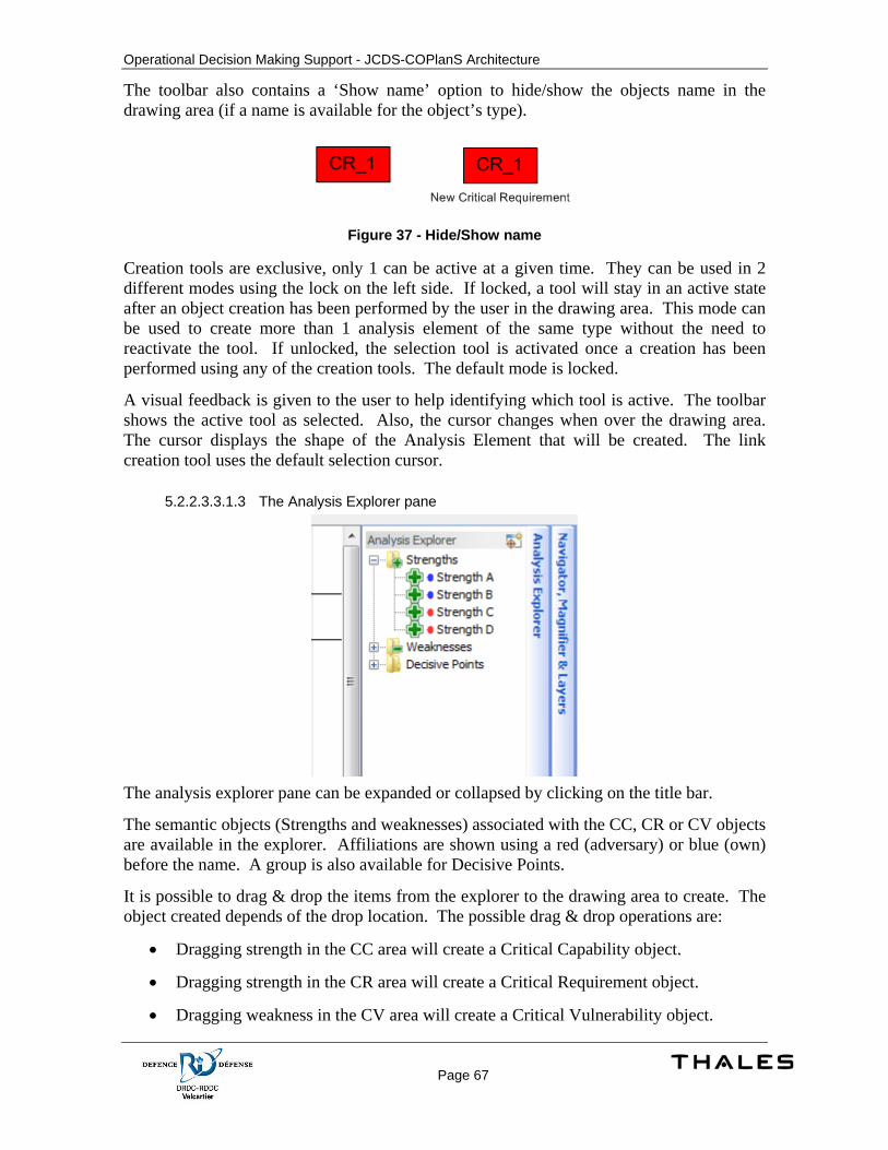
Operational Decision Making Support - JCDS-COPlanS Architecture
Page 67
The toolbar also contains a ‘Show name’ option to hide/show the objects name in the drawing area (if a name is available for the object’s type).
Figure 37 - Hide/Show name
Creation tools are exclusive, only 1 can be active at a given time. They can be used in 2 different modes using the lock on the left side. If locked, a tool will stay in an active state after an object creation has been performed by the user in the drawing area. This mode can be used to create more than 1 analysis element of the same type without the need to reactivate the tool. If unlocked, the selection tool is activated once a creation has been performed using any of the creation tools. The default mode is locked.
A visual feedback is given to the user to help identifying which tool is active. The toolbar shows the active tool as selected. Also, the cursor changes when over the drawing area. The cursor displays the shape of the Analysis Element that will be created. The link creation tool uses the default selection cursor.
5.2.2.3.3.1.3 The Analysis Explorer pane
The analysis explorer pane can be expanded or collapsed by clicking on the title bar.
The semantic objects (Strengths and weaknesses) associated with the CC, CR or CV objects are available in the explorer. Affiliations are shown using a red (adversary) or blue (own) before the name. A group is also available for Decisive Points.
It is possible to drag & drop the items from the explorer to the drawing area to create. The object created depends of the drop location. The possible drag & drop operations are:
• Dragging strength in the CC area will create a Critical Capability object.
• Dragging strength in the CR area will create a Critical Requirement object.
• Dragging weakness in the CV area will create a Critical Vulnerability object.
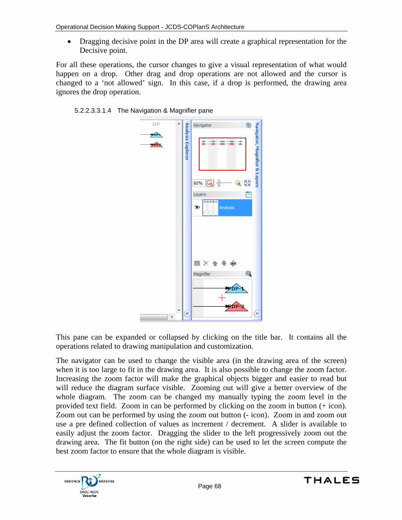
Operational Decision Making Support - JCDS-COPlanS Architecture
Page 68
• Dragging decisive point in the DP area will create a graphical representation for the Decisive point.
For all these operations, the cursor changes to give a visual representation of what would happen on a drop. Other drag and drop operations are not allowed and the cursor is changed to a ‘not allowed’ sign. In this case, if a drop is performed, the drawing area ignores the drop operation.
5.2.2.3.3.1.4 The Navigation & Magnifier pane
This pane can be expanded or collapsed by clicking on the title bar. It contains all the operations related to drawing manipulation and customization.
The navigator can be used to change the visible area (in the drawing area of the screen) when it is too large to fit in the drawing area. It is also possible to change the zoom factor. Increasing the zoom factor will make the graphical objects bigger and easier to read but will reduce the diagram surface visible. Zooming out will give a better overview of the whole diagram. The zoom can be changed my manually typing the zoom level in the provided text field. Zoom in can be performed by clicking on the zoom in button (+ icon). Zoom out can be performed by using the zoom out button (- icon). Zoom in and zoom out use a pre defined collection of values as increment / decrement. A slider is available to easily adjust the zoom factor. Dragging the slider to the left progressively zoom out the drawing area. The fit button (on the right side) can be used to let the screen compute the best zoom factor to ensure that the whole diagram is visible.
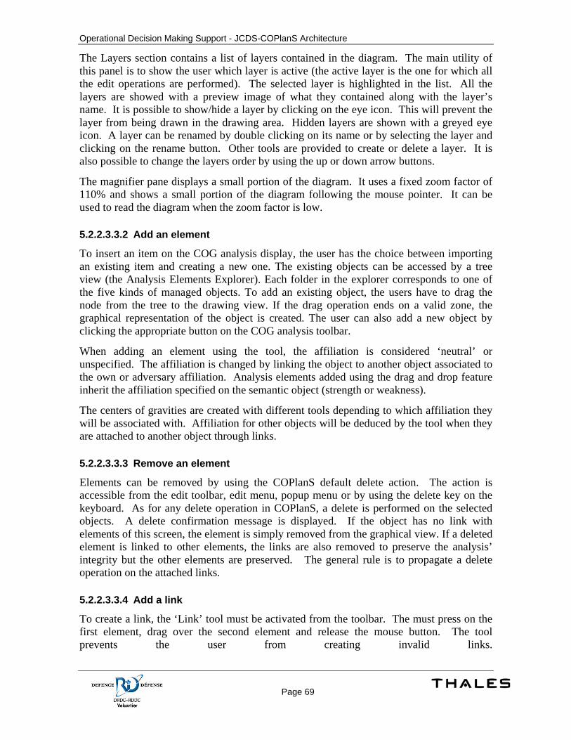
Operational Decision Making Support - JCDS-COPlanS Architecture
Page 69
The Layers section contains a list of layers contained in the diagram. The main utility of this panel is to show the user which layer is active (the active layer is the one for which all the edit operations are performed). The selected layer is highlighted in the list. All the layers are showed with a preview image of what they contained along with the layer’s name. It is possible to show/hide a layer by clicking on the eye icon. This will prevent the layer from being drawn in the drawing area. Hidden layers are shown with a greyed eye icon. A layer can be renamed by double clicking on its name or by selecting the layer and clicking on the rename button. Other tools are provided to create or delete a layer. It is also possible to change the layers order by using the up or down arrow buttons.
The magnifier pane displays a small portion of the diagram. It uses a fixed zoom factor of 110% and shows a small portion of the diagram following the mouse pointer. It can be used to read the diagram when the zoom factor is low.
5.2.2.3.3.2 Add an element
To insert an item on the COG analysis display, the user has the choice between importing an existing item and creating a new one. The existing objects can be accessed by a tree view (the Analysis Elements Explorer). Each folder in the explorer corresponds to one of the five kinds of managed objects. To add an existing object, the users have to drag the node from the tree to the drawing view. If the drag operation ends on a valid zone, the graphical representation of the object is created. The user can also add a new object by clicking the appropriate button on the COG analysis toolbar.
When adding an element using the tool, the affiliation is considered ‘neutral’ or unspecified. The affiliation is changed by linking the object to another object associated to the own or adversary affiliation. Analysis elements added using the drag and drop feature inherit the affiliation specified on the semantic object (strength or weakness).
The centers of gravities are created with different tools depending to which affiliation they will be associated with. Affiliation for other objects will be deduced by the tool when they are attached to another object through links.
5.2.2.3.3.3 Remove an element
Elements can be removed by using the COPlanS default delete action. The action is accessible from the edit toolbar, edit menu, popup menu or by using the delete key on the keyboard. As for any delete operation in COPlanS, a delete is performed on the selected objects. A delete confirmation message is displayed. If the object has no link with elements of this screen, the element is simply removed from the graphical view. If a deleted element is linked to other elements, the links are also removed to preserve the analysis’ integrity but the other elements are preserved. The general rule is to propagate a delete operation on the attached links.
5.2.2.3.3.4 Add a link
To create a link, the ‘Link’ tool must be activated from the toolbar. The must press on the first element, drag over the second element and release the mouse button. The tool prevents the user from creating invalid links.
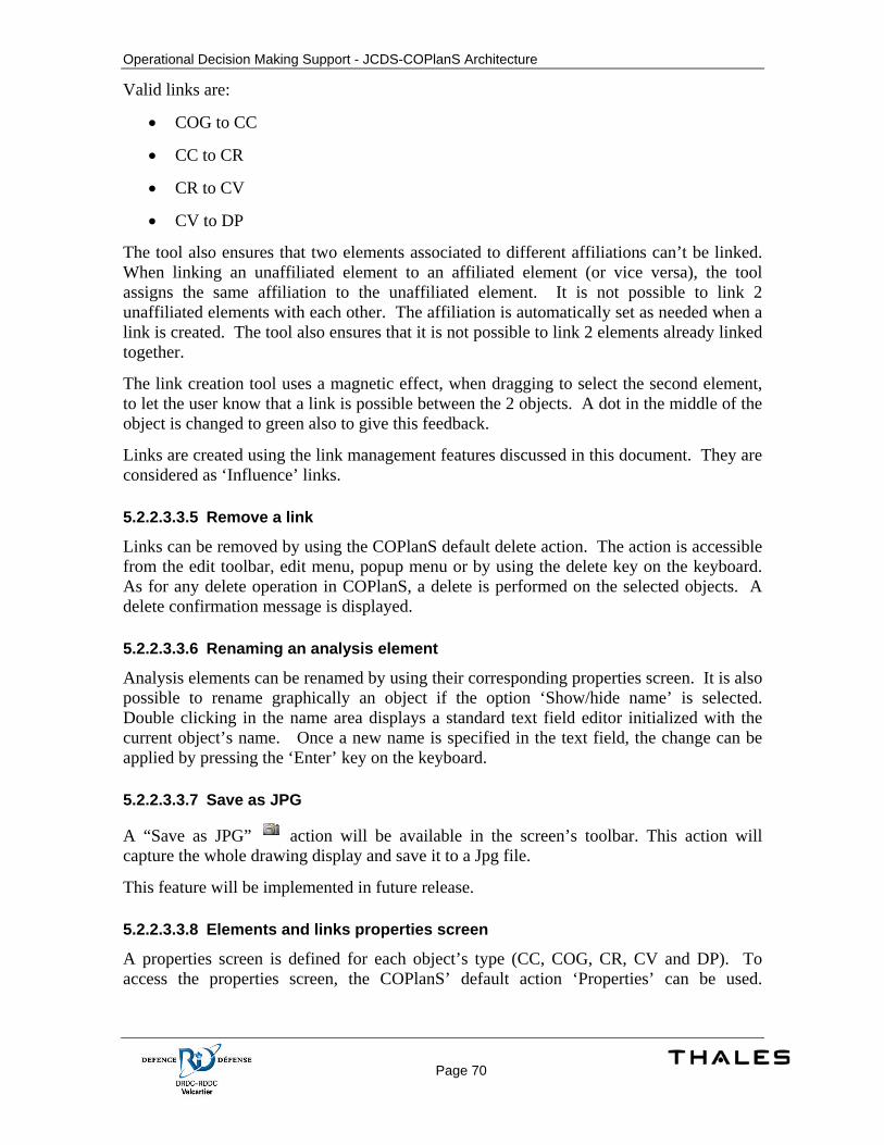
Operational Decision Making Support - JCDS-COPlanS Architecture
Page 70
Valid links are:
• COG to CC
• CC to CR
• CR to CV
• CV to DP
The tool also ensures that two elements associated to different affiliations can’t be linked. When linking an unaffiliated element to an affiliated element (or vice versa), the tool assigns the same affiliation to the unaffiliated element. It is not possible to link 2 unaffiliated elements with each other. The affiliation is automatically set as needed when a link is created. The tool also ensures that it is not possible to link 2 elements already linked together.
The link creation tool uses a magnetic effect, when dragging to select the second element, to let the user know that a link is possible between the 2 objects. A dot in the middle of the object is changed to green also to give this feedback.
Links are created using the link management features discussed in this document. They are considered as ‘Influence’ links.
5.2.2.3.3.5 Remove a link
Links can be removed by using the COPlanS default delete action. The action is accessible from the edit toolbar, edit menu, popup menu or by using the delete key on the keyboard. As for any delete operation in COPlanS, a delete is performed on the selected objects. A delete confirmation message is displayed.
5.2.2.3.3.6 Renaming an analysis element
Analysis elements can be renamed by using their corresponding properties screen. It is also possible to rename graphically an object if the option ‘Show/hide name’ is selected. Double clicking in the name area displays a standard text field editor initialized with the current object’s name. Once a new name is specified in the text field, the change can be applied by pressing the ‘Enter’ key on the keyboard.
5.2.2.3.3.7 Save as JPG
A “Save as JPG” action will be available in the screen’s toolbar. This action will capture the whole drawing display and save it to a Jpg file.
This feature will be implemented in future release.
5.2.2.3.3.8 Elements and links properties screen
A properties screen is defined for each object’s type (CC, COG, CR, CV and DP). To access the properties screen, the COPlanS’ default action ‘Properties’ can be used.
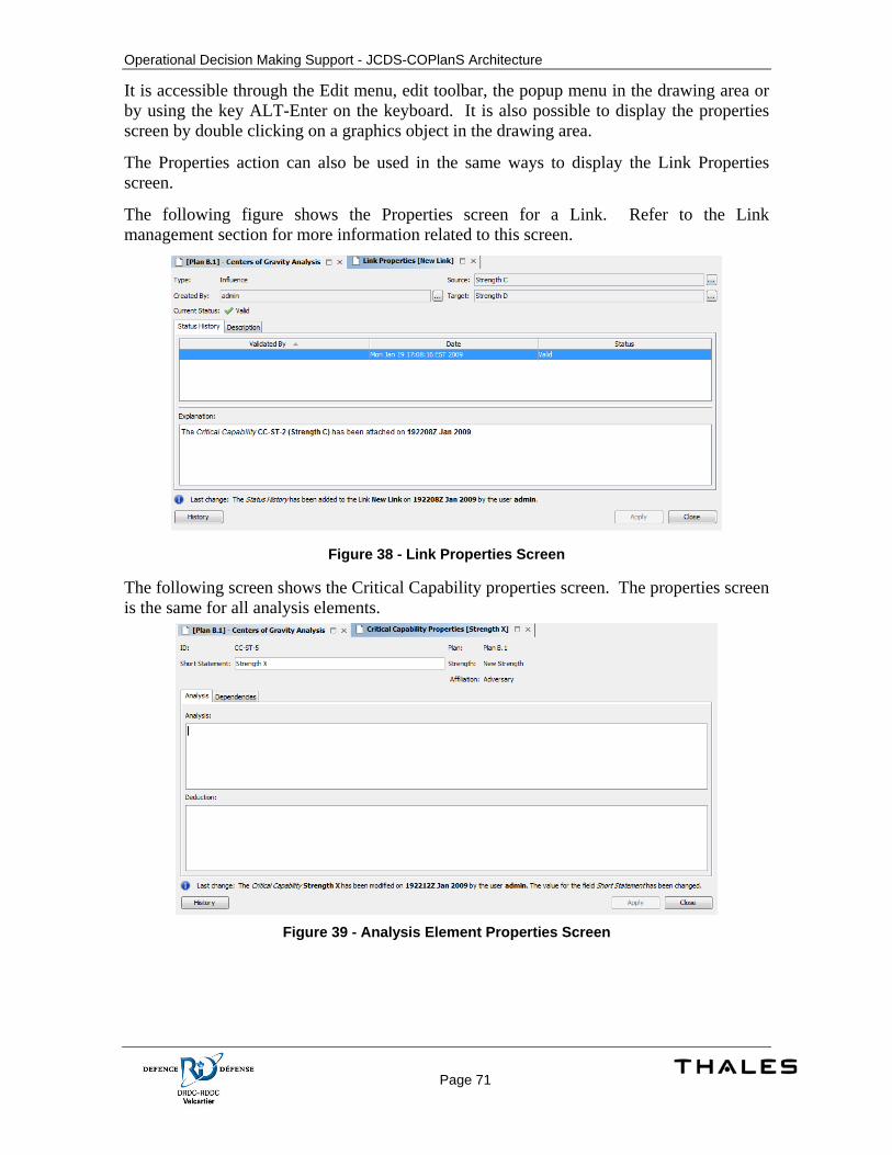
Operational Decision Making Support - JCDS-COPlanS Architecture
Page 71
It is accessible through the Edit menu, edit toolbar, the popup menu in the drawing area or by using the key ALT-Enter on the keyboard. It is also possible to display the properties screen by double clicking on a graphics object in the drawing area.
The Properties action can also be used in the same ways to display the Link Properties screen.
The following figure shows the Properties screen for a Link. Refer to the Link management section for more information related to this screen.
Figure 38 - Link Properties Screen
The following screen shows the Critical Capability properties screen. The properties screen is the same for all analysis elements.
Figure 39 - Analysis Element Properties Screen
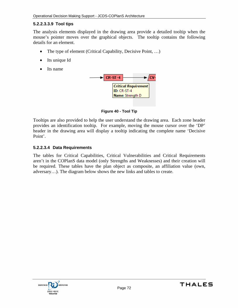
Operational Decision Making Support - JCDS-COPlanS Architecture
Page 72
5.2.2.3.3.9 Tool tips
The analysis elements displayed in the drawing area provide a detailed tooltip when the mouse’s pointer moves over the graphical objects. The tooltip contains the following details for an element.
• The type of element (Critical Capability, Decisive Point, …)
• Its unique Id
• Its name
Figure 40 - Tool Tip
Tooltips are also provided to help the user understand the drawing area. Each zone header provides an identification tooltip. For example, moving the mouse cursor over the ‘DP’ header in the drawing area will display a tooltip indicating the complete name ‘Decisive Point’.
5.2.2.3.4 Data Requirements
The tables for Critical Capabilities, Critical Vulnerabilities and Critical Requirements aren’t in the COPlanS data model (only Strengths and Weaknesses) and their creation will be required. These tables have the plan object as composite, an affiliation value (own, adversary…). The diagram below shows the new links and tables to create.
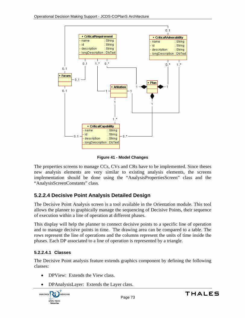
Operational Decision Making Support - JCDS-COPlanS Architecture
Page 73
Figure 41 - Model Changes
The properties screens to manage CCs, CVs and CRs have to be implemented. Since theses new analysis elements are very similar to existing analysis elements, the screens implementation should be done using the “AnalysisPropertiesScreen” class and the “AnalysisScreenConstants” class.
5.2.2.4 Decisive Point Analysis Detailed Design The Decisive Point Analysis screen is a tool available in the Orientation module. This tool allows the planner to graphically manage the sequencing of Decisive Points, their sequence of execution within a line of operation at different phases.
This display will help the planner to connect decisive points to a specific line of operation and to manage decisive points in time. The drawing area can be compared to a table. The rows represent the line of operations and the columns represent the units of time inside the phases. Each DP associated to a line of operation is represented by a triangle.
5.2.2.4.1 Classes
The Decisive Point analysis feature extends graphics component by defining the following classes:
• DPView: Extends the View class.
• DPAnalysisLayer: Extends the Layer class.
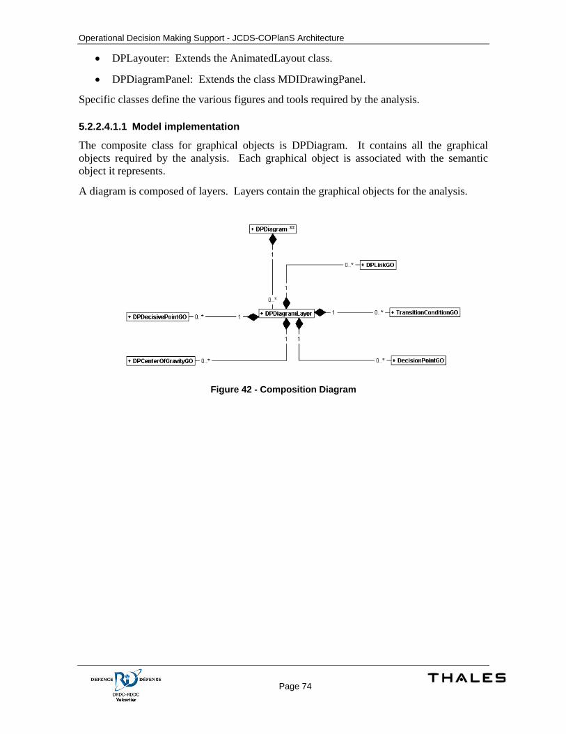
Operational Decision Making Support - JCDS-COPlanS Architecture
Page 74
• DPLayouter: Extends the AnimatedLayout class.
• DPDiagramPanel: Extends the class MDIDrawingPanel.
Specific classes define the various figures and tools required by the analysis.
5.2.2.4.1.1 Model implementation
The composite class for graphical objects is DPDiagram. It contains all the graphical objects required by the analysis. Each graphical object is associated with the semantic object it represents.
A diagram is composed of layers. Layers contain the graphical objects for the analysis.
Figure 42 - Composition Diagram
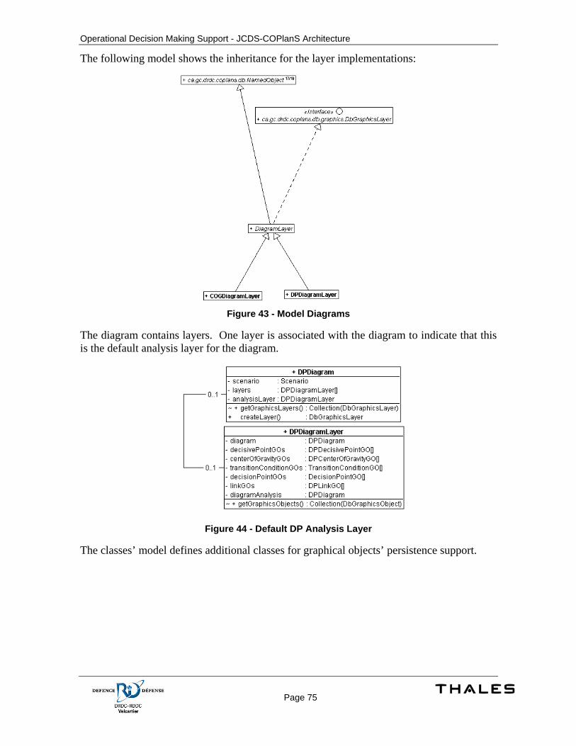
Operational Decision Making Support - JCDS-COPlanS Architecture
Page 75
The following model shows the inheritance for the layer implementations:
Figure 43 - Model Diagrams
The diagram contains layers. One layer is associated with the diagram to indicate that this is the default analysis layer for the diagram.
Figure 44 - Default DP Analysis Layer
The classes’ model defines additional classes for graphical objects’ persistence support.
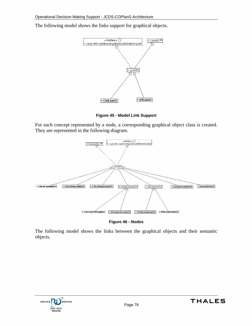
Operational Decision Making Support - JCDS-COPlanS Architecture
Page 76
The following model shows the links support for graphical objects.
Figure 45 - Model Link Support
For each concept represented by a node, a corresponding graphical object class is created. They are represented in the following diagram.
Figure 46 - Nodes
The following model shows the links between the graphical objects and their semantic objects.
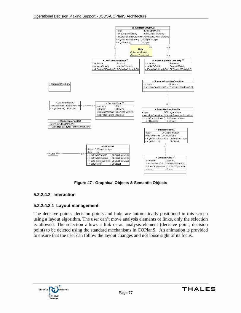
Operational Decision Making Support - JCDS-COPlanS Architecture
Page 77
Figure 47 - Graphical Objects & Semantic Objects
5.2.2.4.2 Interaction
5.2.2.4.2.1 Layout management
The decisive points, decision points and links are automatically positioned in this screen using a layout algorithm. The user can’t move analysis elements or links, only the selection is allowed. The selection allows a link or an analysis element (decisive point, decision point) to be deleted using the standard mechanisms in COPlanS. An animation is provided to ensure that the user can follow the layout changes and not loose sight of its focus.
Operational Decision Making Support - JCDS-COPlanS Architecture
Page 78
Figure 48 - Layout Management
5.2.2.4.2.2 Automatic links managements
When a DP is added or removed from a functional line of operation or when the time of execution associated to a DP has changed, a mechanism responsible for DP sequencing and links integrity over a functional line on operation is triggered. For example, when deleting a DP, the mechanism reconnects the previous DP in the sequence with the one next to the deleted DP, also removing the 2 links that were attached to the deleted DP. A similar operation is performed when inserting a DP between 2 DP already linked.
Figure 49 - DPs Links Management
5.2.2.4.3 User Interface
The Decisive Points Analysis tool allows the user to create different analysis for a plan. Later during the planning process, the analysis is available to create different courses of actions.
5.2.2.4.3.1 Decisive Points Analysis Screen
Object types managed by the screen are:
• Decisive Points Analysis
• COGs (Center of gravity)
• DPs (Decisive Point)

Operational Decision Making Support - JCDS-COPlanS Architecture
Page 79
• Decision Points
• Tasks
• Objectives
• Phases
• Lines of Operation (Functional and Environmental)
These objects can be associated with each other. Some associations are managed graphically; others are managed from properties screens.
Associations managed graphically are:
• DP to DP
• DP to Decision Point (and vice versa)
• DP with Line of Operation (both functional and environmental)
• DP with Phase
• Decision Point with Line of Operation (both functional and environmental)
• Decision Point with Phase
• Task to Decisive Point
• Objective to Decisive Point
The DP Analysis tool leverage the links management feature by using the generic Link to manage links between Decisive Points and Decision Points. These links are categorized as ‘Sequence’ links.
The Decisive Point analysis tool is built on the COPlanS framework. Any operations performed on any objects benefit from the frameworks features (such as undo – redo operations).
The screen focuses on one analysis (depending on the analysis selector on the toolbar). All the operations performed are related to this analysis.
Objects composing an analysis are private to the analysis and are not shared with other analysis. The user can create/edit/remove as many analysis as needed.
The following figure shows the DP Analysis Screen. The screen is divided in 4 distinct sections: The drawing area, the toolbar, the analysis explorer & tools pane and the navigation & magnifier pane.
Operational Decision Making Support - JCDS-COPlanS Architecture
Page 80
Figure 50 – Decisive Points Analysis Screen
5.2.2.4.3.1.1 The drawing area
This is the main display area for the screen and the working area to create the diagram. Objects are positioned automatically on the drawing surface using a layout algorithm. A grid is visible in the background. Rows represent the Functional lines of operation and columns represent the phases. Each rows and columns have a header displaying the object’s ID. The centers of gravity of interest for analysis are displayed on the left and right sides of the area. Own centers of gravity to the left and adversary centers of gravity to the right.
A legend for objective is displayed on the top left corner. For each objective, an icon and a name are drawn.
For each line of operation, a line is painted using the color associated with the line of operation. Decisive points are attached to these lines. At each intersection with the beginning and ending of a phase, an interaction node is drawn (represented by small filled circles). These nodes will be used by the tools (such as the Decisive Point creation tool) to edit the diagram.
Decisive Points and Decision Points object also displays 2 interaction nodes. The first node is located on the left side of the shape. The second node is drawn on the right side of the shape. These nodes are used by the tools to edit the diagram. Specifics regarding these nodes are discussed in the following sections.
The DPs are positioned on their associated functional line of operation and on their respective time value represented by the phase.
Operational Decision Making Support - JCDS-COPlanS Architecture
Page 81
Creation tools interactions like the tools to create a new Decisive Point and the drag and drop operations are limited to the drawing area.
The affiliation is represented by using a different background color for the center of gravities. Blue is used to represents the Own affiliation and red for adversary.
The objects’ ID is always displayed in the center of the graphical objects for decision points and decisive points. The names can be shown optionally by selecting the ‘Show Name’ checkbox on the toolbar. They are drawn under the shape representing the graphical objects.
Scroll bars are available when the diagram’s size is greater than the available space for the drawing area.
The diagram is initialized with a graphical representation of the selected COGs (own and adversary) specified on the analysis. The grid is also initialized depending of the phases and lines of operation specified for the analysis.
5.2.2.4.3.1.1.1 The Decisive Point graphics object
The decisive point shape is a triangle. The ID is displayed in the center. The border color represents the color specified for the objective assigned to the Decisive Point. If no objective is specified, black is used. A color icon is added at the top right of the triangle for each environmental line of operation assigned to the Decisive Point. The icon’s color is the color specified for the environmental line of operation. It is possible to show/hide the tasks attached to the Decisive Point by clicking the arrow button under the triangle. The tasks are displayed in a rectangle under the triangle. If the show name option is selected (from the toolbar), the name is displayed between the triangle and the tasks list.
Colors can be identified easily by referring to the objectives legend at the top left corner of the drawing area or by the icons used for these elements in the explorer.
5.2.2.4.3.1.1.2 The Decision Point graphics object
The decision point shape is a lozenge. No additional information is attached to the graphics object.
5.2.2.4.3.1.2 The toolbar
The toolbar contains the following tools:
• Selection tool (Arrow pointer)
• Analysis Elements creation tools (one for each type)
Operational Decision Making Support - JCDS-COPlanS Architecture
Page 82
• The Decisive Points analysis selector
The Decisive Points analysis selector combo box is used to select on which analysis the screen should work. All the tools in the screen work according to the selected analysis.
The toolbar also contains a ‘Show name’ option to hide/show the objects name in the drawing area (if a name is available for the object’s type).
Creation tools are exclusive, only 1 can be active at a given time. They can be used in 2 different modes using the lock on the left side. If locked, a tool will stay in an active state after an object creation has been performed by the user in the drawing area. This mode can be used to create more than 1 analysis element of the same type without the need to reactivate the tool. If unlocked, the selection tool is activated once a creation has been performed using any of the creation tools. The default mode is locked.
A visual feedback is given to the user to help identifying which tool is active. The toolbar shows the active tool as selected. Also, the cursor changes when over the drawing area. The cursor displays the shape of the Analysis Element that will be created or a representation of the expected result depending of the cursor location on the drawing area.
5.2.2.4.3.1.3 The Analysis Explorer & Tools pane
Figure 51 - Analysis Explorer & Tools
The analysis explorer & tools pane can be expanded or collapsed by clicking on the title bar.

Operational Decision Making Support - JCDS-COPlanS Architecture
Page 83
5.2.2.4.3.1.3.1 The Analysis Explorer
The explorer contains 6 node groups:
• Analysis Decisive Points: Contains the decisive points defined for the analysis which are not represented in the diagram.
• Plan Decisive Points: Contains the decisive points defined on the plan.
• Environmental Lines of Operation: Contains the environmental lines of operation defined for the analysis.
• Objectives: Contains the objectives defined for the analysis.
• Plan Tasks: Contains the tasks defined for the plan.
• Analysis Tasks: Contains the tasks defined for the analysis. Also note that when using a plan task in the context of an analysis, the system creates a task for the analysis. Tasks can be edited for a specific analysis without affecting the whole plan.
It is possible to drag & drop the items from the explorer to the drawing area to create or associate objects. The operation performed depends on the drop location and the dragged item. The possible drag & drop operations are detailed in the following sections.
For all the drag & drop operations, the cursor changes to give a visual representation of what would happen on a drop. The cursor is changed to a ‘not allowed’ sign when a drag and drop operations are not allowed. In this case, if a drop is performed, the drawing area ignores the drop operation.
5.2.2.4.3.1.3.2 The Tools pane
This task pane contains the tools to edit advanced properties and manage the analysis. These tools are covered in following sections of this document.
5.2.2.4.3.1.4 The Navigation & Magnifier pane
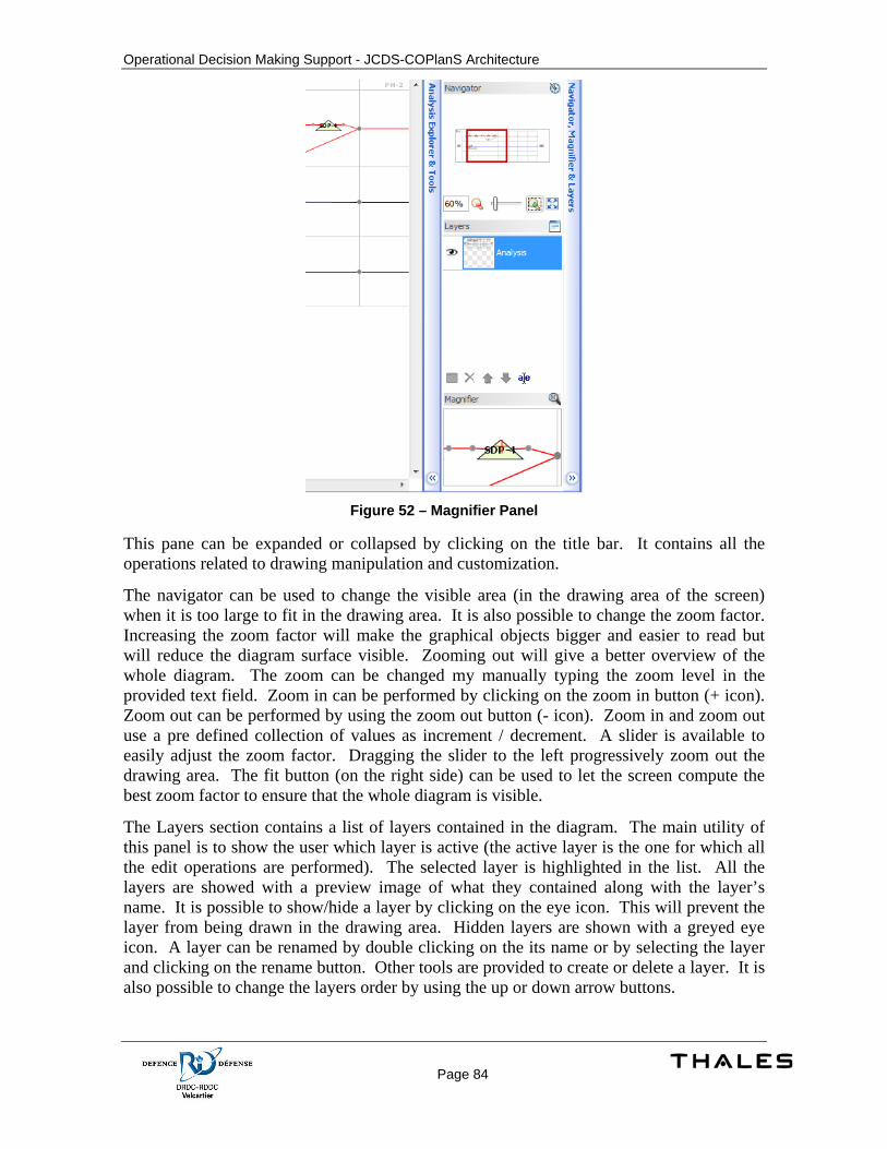
Operational Decision Making Support - JCDS-COPlanS Architecture
Page 84
Figure 52 – Magnifier Panel
This pane can be expanded or collapsed by clicking on the title bar. It contains all the operations related to drawing manipulation and customization.
The navigator can be used to change the visible area (in the drawing area of the screen) when it is too large to fit in the drawing area. It is also possible to change the zoom factor. Increasing the zoom factor will make the graphical objects bigger and easier to read but will reduce the diagram surface visible. Zooming out will give a better overview of the whole diagram. The zoom can be changed my manually typing the zoom level in the provided text field. Zoom in can be performed by clicking on the zoom in button (+ icon). Zoom out can be performed by using the zoom out button (- icon). Zoom in and zoom out use a pre defined collection of values as increment / decrement. A slider is available to easily adjust the zoom factor. Dragging the slider to the left progressively zoom out the drawing area. The fit button (on the right side) can be used to let the screen compute the best zoom factor to ensure that the whole diagram is visible.
The Layers section contains a list of layers contained in the diagram. The main utility of this panel is to show the user which layer is active (the active layer is the one for which all the edit operations are performed). The selected layer is highlighted in the list. All the layers are showed with a preview image of what they contained along with the layer’s name. It is possible to show/hide a layer by clicking on the eye icon. This will prevent the layer from being drawn in the drawing area. Hidden layers are shown with a greyed eye icon. A layer can be renamed by double clicking on the its name or by selecting the layer and clicking on the rename button. Other tools are provided to create or delete a layer. It is also possible to change the layers order by using the up or down arrow buttons.
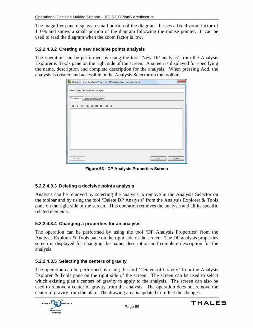
Operational Decision Making Support - JCDS-COPlanS Architecture
Page 85
The magnifier pane displays a small portion of the diagram. It uses a fixed zoom factor of 110% and shows a small portion of the diagram following the mouse pointer. It can be used to read the diagram when the zoom factor is low.
5.2.2.4.3.2 Creating a new decisive points analysis
The operation can be performed by using the tool ‘New DP analysis’ from the Analysis Explorer & Tools pane on the right side of the screen. A screen is displayed for specifying the name, description and complete description for the analysis. When pressing Add, the analysis is created and accessible in the Analysis Selector on the toolbar.
Figure 53 - DP Analysis Properties Screen
5.2.2.4.3.3 Deleting a decisive points analysis
Analysis can be removed by selecting the analysis to remove in the Analysis Selector on the toolbar and by using the tool ‘Delete DP Analysis’ from the Analysis Explorer & Tools pane on the right side of the screen. This operation removes the analysis and all its specific related elements.
5.2.2.4.3.4 Changing a properties for an analysis
The operation can be performed by using the tool ‘DP Analysis Properties’ from the Analysis Explorer & Tools pane on the right side of the screen. The DP analysis properties screen is displayed for changing the name, description and complete description for the analysis.
5.2.2.4.3.5 Selecting the centers of gravity
The operation can be performed by using the tool ‘Centers of Gravity’ from the Analysis Explorer & Tools pane on the right side of the screen. The screen can be used to select which existing plan’s centers of gravity to apply to the analysis. The screen can also be used to remove a center of gravity from the analysis. The operation does not remove the center of gravity from the plan. The drawing area is updated to reflect the changes.
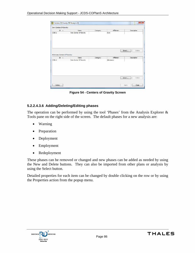
Operational Decision Making Support - JCDS-COPlanS Architecture
Page 86
Figure 54 - Centers of Gravity Screen
5.2.2.4.3.6 Adding/Deleting/Editing phases
The operation can be performed by using the tool ‘Phases’ from the Analysis Explorer & Tools pane on the right side of the screen. The default phases for a new analysis are:
• Warning
• Preparation
• Deployment
• Employment
• Redeployment
These phases can be removed or changed and new phases can be added as needed by using the New and Delete buttons. They can also be imported from other plans or analysis by using the Select button.
Detailed properties for each item can be changed by double clicking on the row or by using the Properties action from the popup menu.
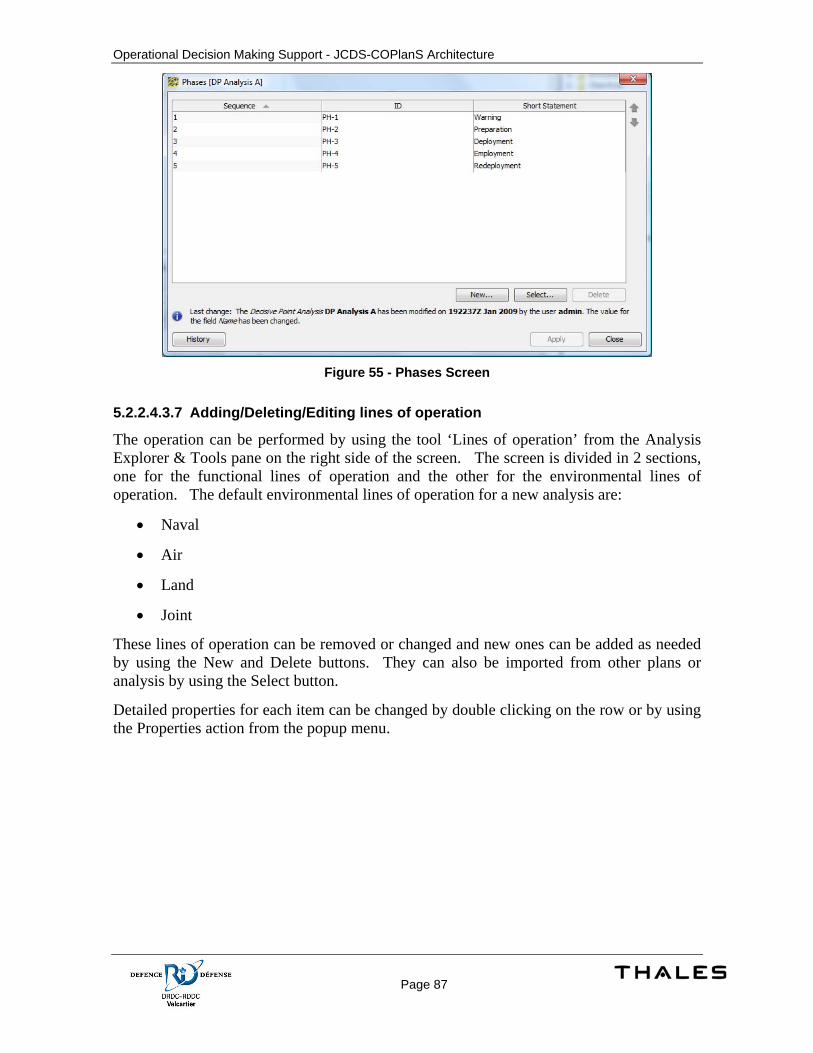
Operational Decision Making Support - JCDS-COPlanS Architecture
Page 87
Figure 55 - Phases Screen
5.2.2.4.3.7 Adding/Deleting/Editing lines of operation
The operation can be performed by using the tool ‘Lines of operation’ from the Analysis Explorer & Tools pane on the right side of the screen. The screen is divided in 2 sections, one for the functional lines of operation and the other for the environmental lines of operation. The default environmental lines of operation for a new analysis are:
• Naval
• Air
• Land
• Joint
These lines of operation can be removed or changed and new ones can be added as needed by using the New and Delete buttons. They can also be imported from other plans or analysis by using the Select button.
Detailed properties for each item can be changed by double clicking on the row or by using the Properties action from the popup menu.
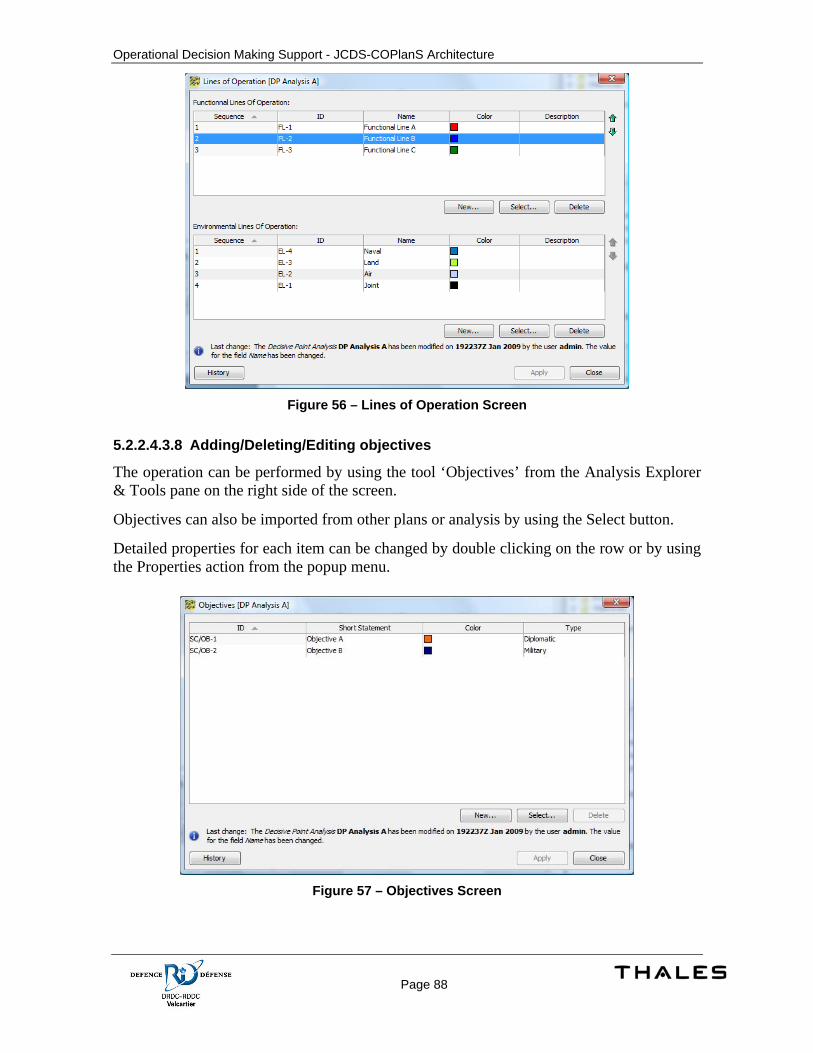
Operational Decision Making Support - JCDS-COPlanS Architecture
Page 88
Figure 56 – Lines of Operation Screen
5.2.2.4.3.8 Adding/Deleting/Editing objectives
The operation can be performed by using the tool ‘Objectives’ from the Analysis Explorer & Tools pane on the right side of the screen.
Objectives can also be imported from other plans or analysis by using the Select button.
Detailed properties for each item can be changed by double clicking on the row or by using the Properties action from the popup menu.
Figure 57 – Objectives Screen
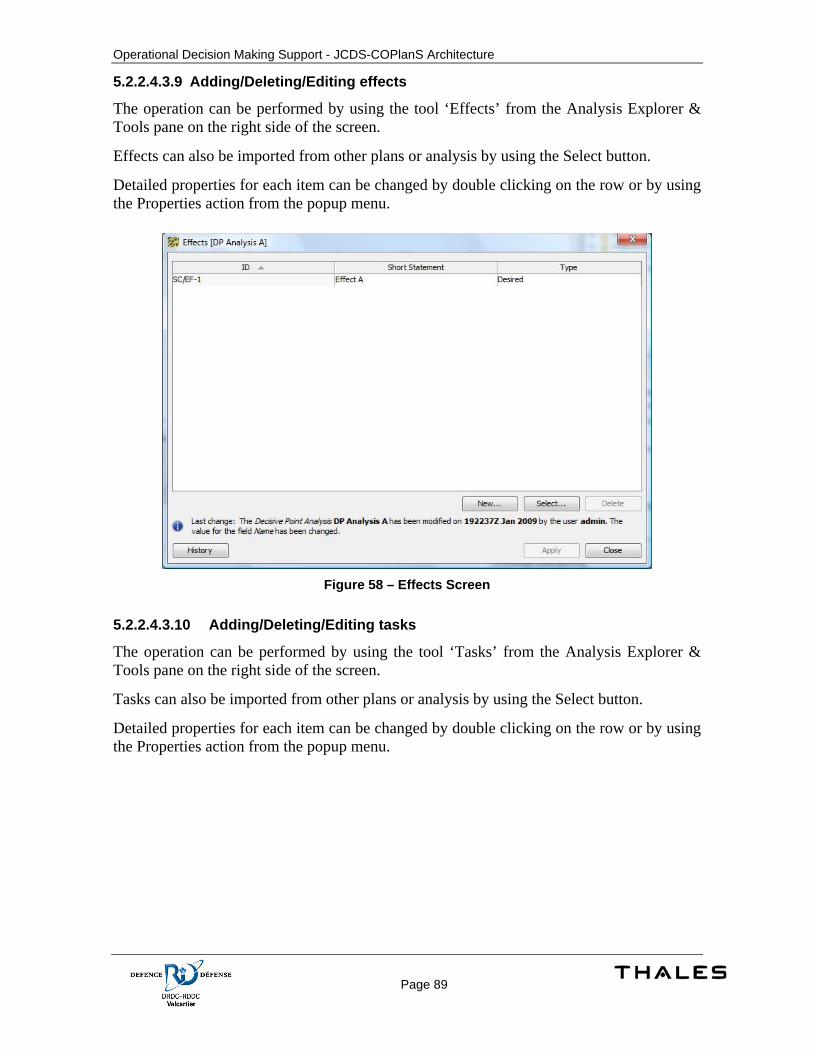
Operational Decision Making Support - JCDS-COPlanS Architecture
Page 89
5.2.2.4.3.9 Adding/Deleting/Editing effects
The operation can be performed by using the tool ‘Effects’ from the Analysis Explorer & Tools pane on the right side of the screen.
Effects can also be imported from other plans or analysis by using the Select button.
Detailed properties for each item can be changed by double clicking on the row or by using the Properties action from the popup menu.
Figure 58 – Effects Screen
5.2.2.4.3.10 Adding/Deleting/Editing tasks
The operation can be performed by using the tool ‘Tasks’ from the Analysis Explorer & Tools pane on the right side of the screen.
Tasks can also be imported from other plans or analysis by using the Select button.
Detailed properties for each item can be changed by double clicking on the row or by using the Properties action from the popup menu.
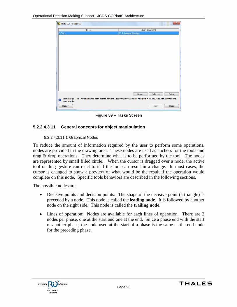
Operational Decision Making Support - JCDS-COPlanS Architecture
Page 90
Figure 59 – Tasks Screen
5.2.2.4.3.11 General concepts for object manipulation
5.2.2.4.3.11.1 Graphical Nodes
To reduce the amount of information required by the user to perform some operations, nodes are provided in the drawing area. These nodes are used as anchors for the tools and drag & drop operations. They determine what is to be performed by the tool. The nodes are represented by small filled circle. When the cursor is dragged over a node, the active tool or drag gesture can react to it if the tool can result in a change. In most cases, the cursor is changed to show a preview of what would be the result if the operation would complete on this node. Specific tools behaviors are described in the following sections.
The possible nodes are:
• Decisive points and decision points: The shape of the decisive point (a triangle) is preceded by a node. This node is called the leading node. It is followed by another node on the right side. This node is called the trailing node.
• Lines of operation: Nodes are available for each lines of operation. There are 2 nodes per phase, one at the start and one at the end. Since a phase end with the start of another phase, the node used at the start of a phase is the same as the end node for the preceding phase.

Operational Decision Making Support - JCDS-COPlanS Architecture
Page 91
5.2.2.4.3.12 Add/Insert a decisive point
The ‘Decisive Point’ creation tool is used to add new Decisive point to the analysis. To create a new DP, the tool must first be selected in the toolbar. The mouse cursor changes when moving over a cell in the grid. The following image shows the default cursor:
Figure 60 – Decisive Point Cursor
The image represents the expected result on tool completion. In this case, it indicates the creation of a new DP. The DP is positioned at the start of the phase. If a DP or a Decision Point is already linked with the start phase node, a branch will be created. Positioning is not important because the layout is computed by the application.
If the mouse cursor is moved over a leading or trailing node of an existing object, the following scenarios are possible:
5.2.2.4.3.12.1 Creating a new branch from a Decision Point/Inserting a new DP after a Decision Point
Figure 61 – Branch Plan
In this case, a new branch is created from the Decision Point. The operation is performed by clicking on the trailing (right) node of a Decision Point. There is no limit for branches.
A new sequence link is added between the Decision Point and the new DP.
Note that if no DP or other Decision Points follow the targeted Decision Point, the default branch is used.
Performing a drag & drop of a Decisive Point from the explorer to the same node produce the same result but no new Decisive Point is created. The existing DP is applied to the analysis.
5.2.2.4.3.12.2 Inserting a new DP before an existing DP
Figure 62 – Inserting DP before another DP
The operation is performed by clicking on the leading (left) node of the existing DP.

Operational Decision Making Support - JCDS-COPlanS Architecture
Page 92
The sequence link previously existing between the 2 previous objects (if any) is re-linked as target to the new DP. A new sequence link is added between the new DP and the following DP. For example, for the situation where DP A and DP B are linked together with link Z and DP C is inserted, link Z target is changed to DP C and a new link Y is added with DP C as source and DP B as target.
Performing a drag & drop of a Decisive Point from the explorer to the same node produce the same result but no new Decisive Point is created. The existing DP is applied to the analysis.
5.2.2.4.3.12.3 Inserting a new DP after an existing DP
Figure 63 – Inserting DP after another DP
The operation is performed by clicking on the trailing (right) node of an existing DP.
The sequence link previously existing between the 2 previous objects (if any) is re-linked as target to the new DP. A new sequence link is added between the new DP and the following DP. For example, for the situation where DP A and DP B are linked together with link Z and DP C is inserted, link Z target is changed to DP C and a new link Y is added with DP C as source and DP B as target. From a link point of view, this is the same as when inserting a new DP before an existing DP.
Performing a drag & drop of a Decisive Point from the explorer to the same node produce the same result but no new Decisive Point is created. The existing DP is applied to the analysis.
5.2.2.4.3.12.4 Inserting a new DP before a Decision Point
Figure 64 – Inserting DP before a Decision Point
The operation is performed by clicking on the leading (left) node of an existing Decision Point.
The sequence link previously existing between the 2 previous objects (if any) is re-linked as target to the new DP. A new sequence link is added between the new DP and the following Decision Point. For example, for the situation where DP A and Decision Point B are linked together with link Z and DP C is inserted, link Z target is changed to DP C and a new link Y is added with DP C as source and Decision Point B as target.

Operational Decision Making Support - JCDS-COPlanS Architecture
Page 93
Performing a drag & drop of a Decisive Point from the explorer to the same node produce the same result but no new Decisive Point is created. The existing DP is applied to the analysis.

Operational Decision Making Support - JCDS-COPlanS Architecture
Page 94
5.2.2.4.3.13 Add/Insert a decision point
The ‘Decision Point’ creation tool is used to add new Decision point to the analysis. To create a new decision point, the tool must first be selected in the toolbar. The mouse cursor changes when moving over a cell in the grid. The following image shows the default cursor:
Figure 65 – Decision Point Cursor
The image represents the expected result on tool completion. In this case, it indicates the creation of a new decision point. The decision point is positioned at the start of the phase. If a decision point or a decisive point is already linked with the start phase node, a branch will be created. Positioning is not important because the layout is computed by the application.
If the mouse cursor is moved over a leading or trailing node of an existing object, the following scenarios are possible:
5.2.2.4.3.13.1 Creating a new branch from a Decision Point/Inserting a new Decision Point after a Decision Point
In this case, a new branch is created from the Decision Point. The operation is performed by clicking on the trailing (right) node of a Decision Point. There is no limit for branches.
A new sequence link is added between the existing Decision Point and the new Decision Point.
Note that if no DP or other Decision Points follow the targeted Decision Point, the default branch is used.
5.2.2.4.3.13.2 Inserting a new Decision Point before an existing Decisive Point
The operation is performed by clicking on the leading (left) node of the existing DP.
The sequence link previously existing between the 2 previous objects (if any) is re-linked as target to the new Decision Point. A new sequence link is added between the new Decision Point and the following DP. For example, for the situation where DP A and DP B are linked together with link Z and Decision Point C is inserted before DP B, link Z target is

Operational Decision Making Support - JCDS-COPlanS Architecture
Page 95
changed to Decision Point C and a new link Y is added with Decision Point C as source and DP B as target.

Operational Decision Making Support - JCDS-COPlanS Architecture
Page 96
5.2.2.4.3.13.3 Inserting a new Decision Point after an existing Decisive Point
The operation is performed by clicking on the trailing (right) node of an existing DP.
The sequence link previously existing between the 2 previous objects (if any) is re-linked as target to the new Decision Point. A new sequence link is added between the new Decision Point and the following DP. For example, for the situation where DP A and DP B are linked together with link Z and Decision Point C is inserted, link Z target is changed to Decision Point C and a new link Y is added with Decision Point C as source and DP B as target. From a link point of view, this is the same as when inserting a new Decision Point before an existing DP.
5.2.2.4.3.13.4 Inserting a new Decision Point before a Decision Point
The operation is performed by clicking on the leading (left) node of an existing Decision Point.
The sequence link previously existing between the 2 previous objects (if any) is re-linked as target to the new Decision Point. A new sequence link is added between the new Decision Point and the following Decision Point. For example, for the situation where DP A and Decision Point B are linked together with link Z and Decision Point C is inserted, link Z target is changed to Decision Point C and a new link Y is added with Decision Point C as source and Decision Point B as target.
5.2.2.4.3.14 Removing a Decisive Point or a Decision Point
Decisive Points and Decision Points can be removed by using the COPlanS default delete action. The action is accessible from the edit toolbar, edit menu, popup menu or by using the delete key on the keyboard. As for any delete operation in COPlanS, a delete is performed on the selected objects. A delete confirmation message is displayed.
When a delete is performed, the sequence links with this element are modified or removed. If for example DP A is link to DP B and DP B is linked to DP C, removing DP B will result in the deletion of the link between DP B and DP C. The target with for the link between DP A and DP B is changed from DP B to DP C to preserve the sequence for the line of operation. When removing a Decision Point, all the branches starting from this Decision Point are reattached to the Phase starting node.
Operational Decision Making Support - JCDS-COPlanS Architecture
Page 97
5.2.2.4.3.15 Removing a Link
Links are automatically managed by the Decisive Point analysis screen and by using integrity mechanisms such as triggers. Thus it is not possible to manually remove sequence links or manually change the source or the target of a link. This ensures that no invalid sequences are present in the analysis.
5.2.2.4.3.16 Objective assignment
A DP can be assigned to an objective by dragging the objective from the explorer to the Decisive Point. If an objective is already associated with the Decisive Point, the operation replaces the associated objective with the new one. A visual color feedback is given on the shape by changing the border color of the triangle.
The assignment can be removed by using the Decisive Point properties screen and by specifying <unspecified> as value for Objective.
5.2.2.4.3.17 Environmental line of operation assignment
A DP can be assigned to a line of operation by dragging the environmental line of operation from the explorer to the Decisive Point. It is possible to assign more than one environmental line of operation with the same Decisive Point. A visual color feedback is given on the shape by adding a color icon on the top right corner of the Decisive Point.
An assignment can be removed by using the Decisive Point properties screen. From the Lines of Operation list panel, select the row representing the environmental line of operation and use the delete action (located at the bottom of the list or from the default COPlanS’ delete action in the Edit menu).
5.2.2.4.3.18 Task assignment
A DP can be assigned to a task by dragging the task from the explorer to the Decisive Point. It is possible to assign more than one task with the same Decisive Point. A visual color feedback is given on the shape by adding the task in the rectangle zone under the triangle. If the zone is not visible, it can be shown by selected the Decisive Point and clicking the down arrow under the triangle. The arrow button is only visible if at least one task is assigned to the Decisive Point.
An assignment can be removed by using the Decisive Point properties screen. From the Tasks panel, select the row representing the task and use the delete action (located at the bottom of the list or from the default COPlanS’ delete action in the Edit menu).
5.2.2.4.3.19 Renaming a Decision Point or a Decisive Point
Decision Points and Decisive Points can be renamed by using their corresponding properties screen. It is also possible to rename graphically an object if the option ‘Show/hide name’ is selected. Double clicking in the name area displays a standard text field editor initialized with the current object’s name. Once a new is specified in the text field, the change can be applied by pressing the ‘Enter’ key on the keyboard.
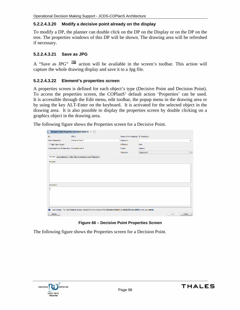
Operational Decision Making Support - JCDS-COPlanS Architecture
Page 98
5.2.2.4.3.20 Modify a decisive point already on the display
To modify a DP, the planner can double click on the DP on the Display or on the DP on the tree. The properties windows of this DP will be shown. The drawing area will be refreshed if necessary.
5.2.2.4.3.21 Save as JPG
A “Save as JPG” action will be available in the screen’s toolbar. This action will capture the whole drawing display and save it to a Jpg file.
5.2.2.4.3.22 Element’s properties screen
A properties screen is defined for each object’s type (Decisive Point and Decision Point). To access the properties screen, the COPlanS’ default action ‘Properties’ can be used. It is accessible through the Edit menu, edit toolbar, the popup menu in the drawing area or by using the key ALT-Enter on the keyboard. It is activated for the selected object in the drawing area. It is also possible to display the properties screen by double clicking on a graphics object in the drawing area.
The following figure shows the Properties screen for a Decisive Point.
Figure 66 – Decisive Point Properties Screen
The following figure shows the Properties screen for a Decision Point.
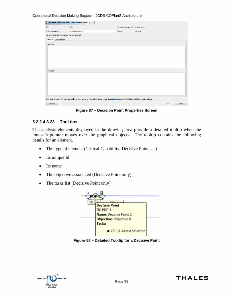
Operational Decision Making Support - JCDS-COPlanS Architecture
Page 99
Figure 67 – Decision Point Properties Screen
5.2.2.4.3.23 Tool tips
The analysis elements displayed in the drawing area provide a detailed tooltip when the mouse’s pointer moves over the graphical objects. The tooltip contains the following details for an element.
• The type of element (Critical Capability, Decisive Point, …)
• Its unique Id
• Its name
• The objective associated (Decisive Point only)
• The tasks list (Decisive Point only)
Figure 68 – Detailed Tooltip for a Decisive Point
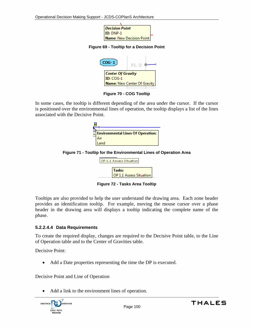
Operational Decision Making Support - JCDS-COPlanS Architecture
Page 100
Figure 69 - Tooltip for a Decision Point
Figure 70 - COG Tooltip
In some cases, the tooltip is different depending of the area under the cursor. If the cursor is positioned over the environmental lines of operation, the tooltip displays a list of the lines associated with the Decisive Point.
Figure 71 - Tooltip for the Environmental Lines of Operation Area
Figure 72 - Tasks Area Tooltip
Tooltips are also provided to help the user understand the drawing area. Each zone header provides an identification tooltip. For example, moving the mouse cursor over a phase header in the drawing area will displays a tooltip indicating the complete name of the phase.
5.2.2.4.4 Data Requirements
To create the required display, changes are required to the Decisive Point table, to the Line of Operation table and to the Center of Gravities table.
Decisive Point:
• Add a Date properties representing the time the DP is executed.
Decisive Point and Line of Operation
• Add a link to the environment lines of operation.
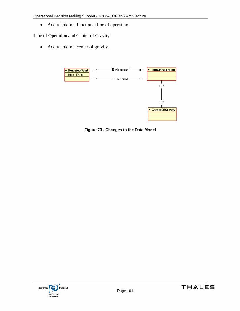
Operational Decision Making Support - JCDS-COPlanS Architecture
Page 101
• Add a link to a functional line of operation.
Line of Operation and Center of Gravity:
• Add a link to a center of gravity.
Figure 73 - Changes to the Data Model

Operational Decision Making Support - JCDS-COPlanS Architecture
Page 102
5.3 Criteria Management
5.3.1 Concept of Execution The criteria management aim at improving the criteria definition and to offer mechanisms for selecting criteria.
During the COA Development activity, the user must select a set of criteria that can be used by the system to compare the developed COAs and propose a ranking to the user. The current implementation provides a screen where the user manually selects the criteria. The proposed implementation allows the user to define sets of criteria targeted at specific operation type (domestic, expedition) and scenarios. These sets of criteria are defined according to the doctrine but can be extended to other scenarios. It also provides a search feature within the Criteria screen. The search feature searches within the existing plans and within the criteria sets specified by the doctrine. The user can then select in the result window the criteria to apply to his plan.
5.3.2 Design Description The proposed criteria management implementation requires changes in the data and class models used in the application. Most of the current model’s support for criteria stays unchanged. Some classes, properties and associations need to be added. This section explains for each class/table the changes required.
5.3.2.1 General Considerations and Limitations Built-in objects are managed by the database layer. The metadata for the class must specify the field used to identify the built-in instances. The database layer uses this metadata specification to determine if an instance is built-in or user defined. Security mechanisms are automatically applied to these instances and no additional code is needed. The screen framework and other GUI components use the same Meta specification to lock operations in the user interface. Similar mechanisms also apply for logging support, SQL requests or object versioning if the metadata are specified.
The framework manages the following properties for the model’s objects if the metadata have been specified.
• GUI representation (names, icons)
• Persistence and transactions
• Basic editors and renderers for basic properties
• Security & Privileges
• Notification mechanisms for object change tracking
• Objects synchronization between clients
• Built-in instances management
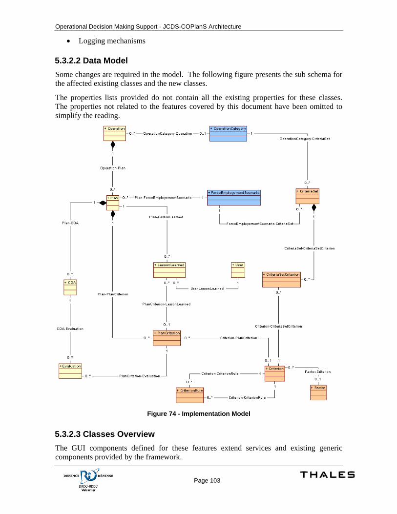
Operational Decision Making Support - JCDS-COPlanS Architecture
Page 103
• Logging mechanisms
5.3.2.2 Data Model Some changes are required in the model. The following figure presents the sub schema for the affected existing classes and the new classes.
The properties lists provided do not contain all the existing properties for these classes. The properties not related to the features covered by this document have been omitted to simplify the reading.
Figure 74 - Implementation Model
5.3.2.3 Classes Overview The GUI components defined for these features extend services and existing generic components provided by the framework.
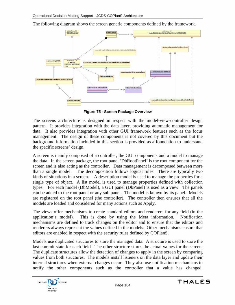
Operational Decision Making Support - JCDS-COPlanS Architecture
Page 104
The following diagram shows the screen generic components defined by the framework.
Figure 75 - Screen Package Overview
The screens architecture is designed in respect with the model-view-controller design pattern. It provides integration with the data layer, providing automatic management for data. It also provides integration with other GUI framework features such as the focus management. The design of these components is not covered by this document but the background information included in this section is provided as a foundation to understand the specific screens’ design.
A screen is mainly composed of a controller, the GUI components and a model to manage the data. In the screen package, the root panel ‘DbRootPanel’ is the root component for the screen and is also acting as the controller. Data management is decomposed between more than a single model. The decomposition follows logical rules. There are typically two kinds of situations in a screen. A description model is used to manage the properties for a single type of object. A list model is used to manage properties defined with collection types. For each model (DbModel), a GUI panel (DbPanel) is used as a view. The panels can be added to the root panel or any sub panel. The model is known by its panel. Models are registered on the root panel (the controller). The controller then ensures that all the models are loaded and considered for many actions such as Apply.
The views offer mechanisms to create standard editors and renderers for any field (in the application’s model). This is done by using the Meta information. Notification mechanisms are defined to track changes on the editor and to ensure that the editors and renderers always represent the values defined in the models. Other mechanisms ensure that editors are enabled in respect with the security rules defined by COPlanS.
Models use duplicated structures to store the managed data. A structure is used to store the last commit state for each field. The other structure stores the actual values for the screen. The duplicate structures allow the detection of changes to apply in the screen by comparing values from both structures. The models install listeners on the data layer and update their internal structures when external changes occur. They also use notification mechanisms to notify the other components such as the controller that a value has changed.
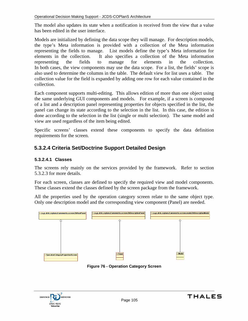
Operational Decision Making Support - JCDS-COPlanS Architecture
Page 105
The model also updates its state when a notification is received from the view that a value has been edited in the user interface.
Models are initialized by defining the data scope they will manage. For description models, the type’s Meta information is provided with a collection of the Meta information representing the fields to manage. List models define the type’s Meta information for elements in the collection. It also specifies a collection of the Meta information representing the fields to manage for elements in the collection. In both cases, the view components may use the data scope. For a list, the fields’ scope is also used to determine the columns in the table. The default view for list uses a table. The collection value for the field is expanded by adding one row for each value contained in the collection.
Each component supports multi-editing. This allows edition of more than one object using the same underlying GUI components and models. For example, if a screen is composed of a list and a description panel representing properties for objects specified in the list, the panel can change its state according to the selection in the list. In this case, the edition is done according to the selection in the list (single or multi selection). The same model and view are used regardless of the item being edited.
Specific screens’ classes extend these components to specify the data definition requirements for the screen.
5.3.2.4 Criteria Set/Doctrine Support Detailed Design
5.3.2.4.1 Classes
The screens rely mainly on the services provided by the framework. Refer to section 5.3.2.3 for more details.
For each screen, classes are defined to specify the required view and model components. These classes extend the classes defined by the screen package from the framework.
All the properties used by the operation category screen relate to the same object type. Only one description model and the corresponding view component (Panel) are needed.
Figure 76 - Operation Category Screen
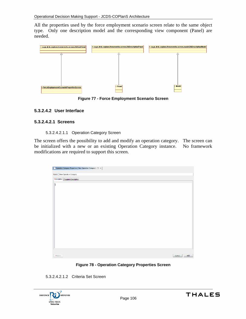
Operational Decision Making Support - JCDS-COPlanS Architecture
Page 106
All the properties used by the force employment scenario screen relate to the same object type. Only one description model and the corresponding view component (Panel) are needed.
Figure 77 - Force Employment Scenario Screen
5.3.2.4.2 User Interface
5.3.2.4.2.1 Screens
5.3.2.4.2.1.1 Operation Category Screen
The screen offers the possibility to add and modify an operation category. The screen can be initialized with a new or an existing Operation Category instance. No framework modifications are required to support this screen.
Figure 78 - Operation Category Properties Screen
5.3.2.4.2.1.2 Criteria Set Screen
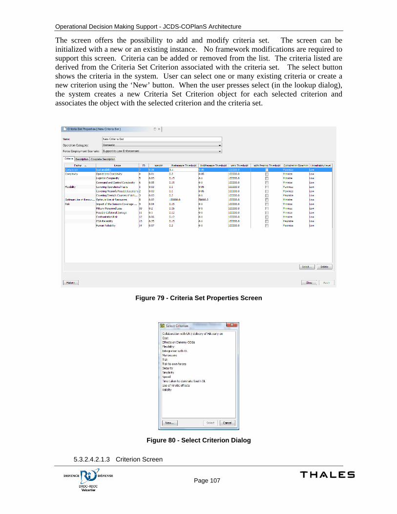
Operational Decision Making Support - JCDS-COPlanS Architecture
Page 107
The screen offers the possibility to add and modify criteria set. The screen can be initialized with a new or an existing instance. No framework modifications are required to support this screen. Criteria can be added or removed from the list. The criteria listed are derived from the Criteria Set Criterion associated with the criteria set. The select button shows the criteria in the system. User can select one or many existing criteria or create a new criterion using the ‘New’ button. When the user presses select (in the lookup dialog), the system creates a new Criteria Set Criterion object for each selected criterion and associates the object with the selected criterion and the criteria set.
Figure 79 - Criteria Set Properties Screen
Figure 80 - Select Criterion Dialog
5.3.2.4.2.1.3 Criterion Screen
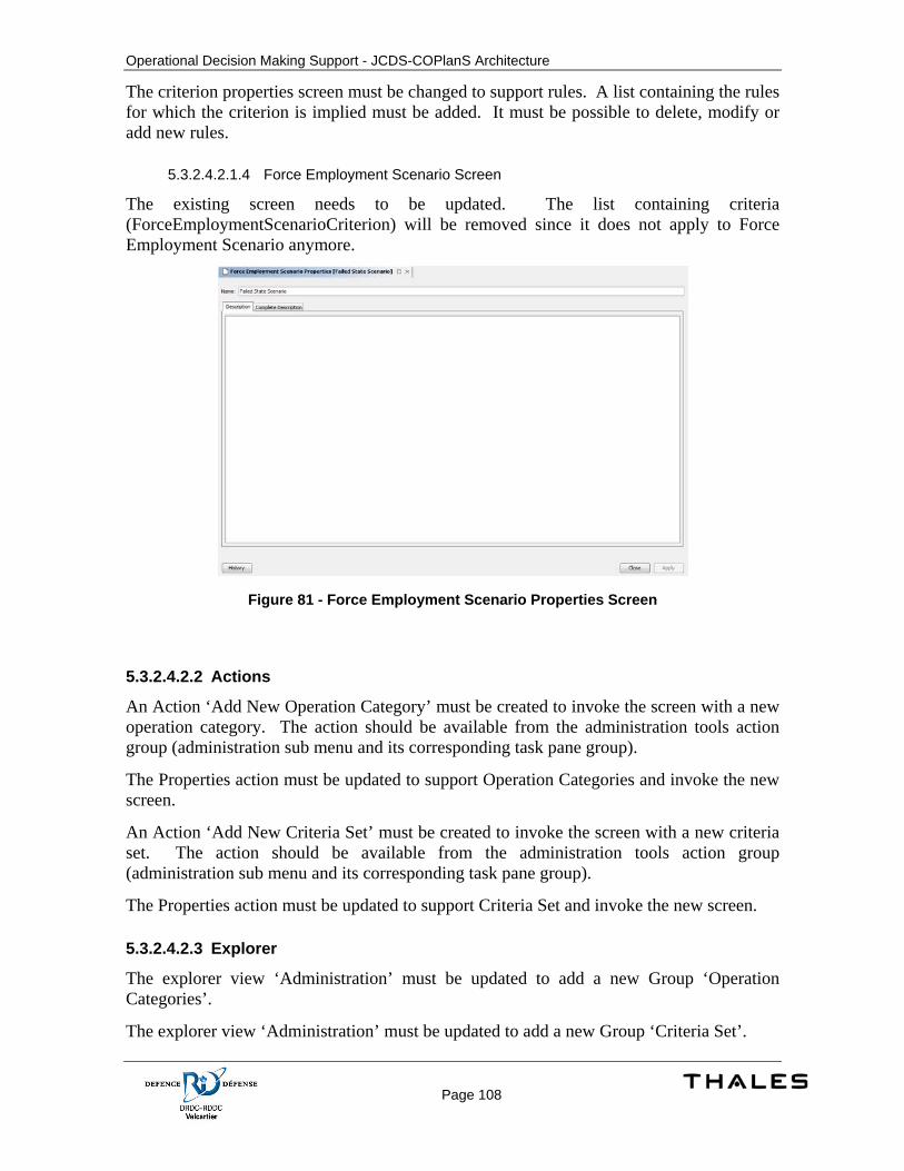
Operational Decision Making Support - JCDS-COPlanS Architecture
Page 108
The criterion properties screen must be changed to support rules. A list containing the rules for which the criterion is implied must be added. It must be possible to delete, modify or add new rules.
5.3.2.4.2.1.4 Force Employment Scenario Screen
The existing screen needs to be updated. The list containing criteria (ForceEmploymentScenarioCriterion) will be removed since it does not apply to Force Employment Scenario anymore.
Figure 81 - Force Employment Scenario Properties Screen
5.3.2.4.2.2 Actions
An Action ‘Add New Operation Category’ must be created to invoke the screen with a new operation category. The action should be available from the administration tools action group (administration sub menu and its corresponding task pane group).
The Properties action must be updated to support Operation Categories and invoke the new screen.
An Action ‘Add New Criteria Set’ must be created to invoke the screen with a new criteria set. The action should be available from the administration tools action group (administration sub menu and its corresponding task pane group).
The Properties action must be updated to support Criteria Set and invoke the new screen.
5.3.2.4.2.3 Explorer
The explorer view ‘Administration’ must be updated to add a new Group ‘Operation Categories’.
The explorer view ‘Administration’ must be updated to add a new Group ‘Criteria Set’.
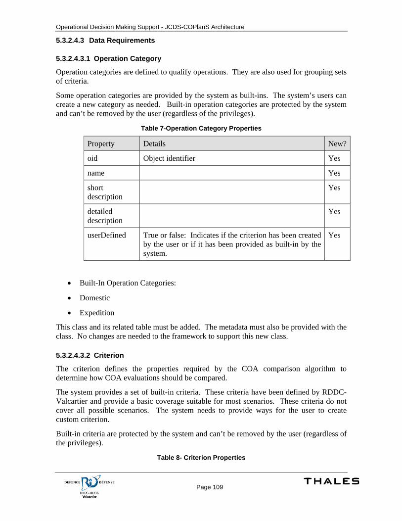
Operational Decision Making Support - JCDS-COPlanS Architecture
Page 109
5.3.2.4.3 Data Requirements
5.3.2.4.3.1 Operation Category
Operation categories are defined to qualify operations. They are also used for grouping sets of criteria.
Some operation categories are provided by the system as built-ins. The system’s users can create a new category as needed. Built-in operation categories are protected by the system and can’t be removed by the user (regardless of the privileges).
Table 7-Operation Category Properties
Property Details New?
oid Object identifier Yes
name Yes
short description
Yes
detailed description
Yes
userDefined True or false: Indicates if the criterion has been created by the user or if it has been provided as built-in by the system.
Yes
• Built-In Operation Categories:
• Domestic
• Expedition
This class and its related table must be added. The metadata must also be provided with the class. No changes are needed to the framework to support this new class.
5.3.2.4.3.2 Criterion
The criterion defines the properties required by the COA comparison algorithm to determine how COA evaluations should be compared.
The system provides a set of built-in criteria. These criteria have been defined by RDDC-Valcartier and provide a basic coverage suitable for most scenarios. These criteria do not cover all possible scenarios. The system needs to provide ways for the user to create custom criterion.
Built-in criteria are protected by the system and can’t be removed by the user (regardless of the privileges).
Table 8- Criterion Properties
Operational Decision Making Support - JCDS-COPlanS Architecture
Page 110
Property Details New?
name No
short description
No
detailed description
No
distributional True or false: Determines if the evaluation should be defined by using a probabilities table.
No
identification No
nature Ordinal or Cardinal. No
userDefined True or false: Indicates if the criterion has been created by the user or if it has been provided as built-in by the system.
No
factor Association with Factor No
Built-In Criteria:
• C1: Covering Operational Tasks
• C2: Covering Mission’s Possible Locations
• C3: Covering Enemy’s COA
• C4: Operations Complexity
• C5: Logistics Complexity
• C6: Command and Control Complexity
• C7: Sustainability
• C8: Cost of Resources
• C9: Impact of the Sensors Coverage Gap
• C10: Military Personnel Loss
• C11: Collateral Damage
• C12: Confrontation Risk
• C13: COA Equipment Reliability
• C14: COA Personnel Effectiveness
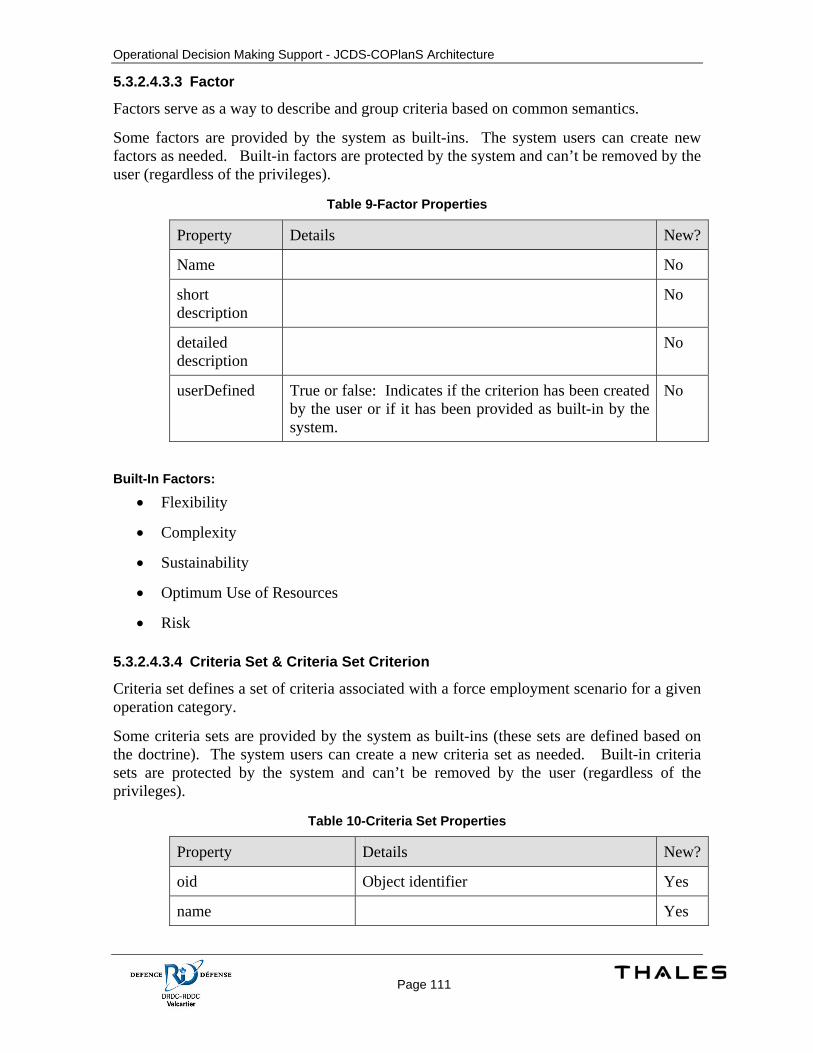
Operational Decision Making Support - JCDS-COPlanS Architecture
Page 111
5.3.2.4.3.3 Factor
Factors serve as a way to describe and group criteria based on common semantics.
Some factors are provided by the system as built-ins. The system users can create new factors as needed. Built-in factors are protected by the system and can’t be removed by the user (regardless of the privileges).
Table 9-Factor Properties
Property Details New?
Name No
short description
No
detailed description
No
userDefined True or false: Indicates if the criterion has been created by the user or if it has been provided as built-in by the system.
No
Built-In Factors:
• Flexibility
• Complexity
• Sustainability
• Optimum Use of Resources
• Risk
5.3.2.4.3.4 Criteria Set & Criteria Set Criterion
Criteria set defines a set of criteria associated with a force employment scenario for a given operation category.
Some criteria sets are provided by the system as built-ins (these sets are defined based on the doctrine). The system users can create a new criteria set as needed. Built-in criteria sets are protected by the system and can’t be removed by the user (regardless of the privileges).
Table 10-Criteria Set Properties
Property Details New?
oid Object identifier Yes
name Yes
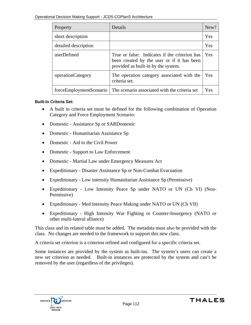
Operational Decision Making Support - JCDS-COPlanS Architecture
Page 112
Property Details New?
short description Yes
detailed description Yes
userDefined True or false: Indicates if the criterion has been created by the user or if it has been provided as built-in by the system.
Yes
operationCategory The operation category associated with the criteria set.
Yes
forceEmploymentScenario The scenario associated with the criteria set Yes Built-In Criteria Set:
• A built in criteria set must be defined for the following combination of Operation Category and Force Employment Scenario:
• Domestic - Assistance Sp or SARDomestic
• Domestic - Humanitarian Assistance Sp
• Domestic - Aid to the Civil Power
• Domestic - Support to Law Enforcement
• Domestic - Martial Law under Emergency Measures Act
• Expeditionary - Disaster Assistance Sp or Non-Combat Evacuation
• Expeditionary - Low intensity Humanitarian Assistance Sp (Permissive)
• Expeditionary - Low Intensity Peace Sp under NATO or UN (Ch VI) (Non-Permissive)
• Expeditionary - Med Intensity Peace Making under NATO or UN (Ch VII)
• Expeditionary - High Intensity War Fighting or Counter-Insurgency (NATO or other multi-lateral alliance)
This class and its related table must be added. The metadata must also be provided with the class. No changes are needed to the framework to support this new class.
A criteria set criterion is a criterion refined and configured for a specific criteria set.
Some instances are provided by the system as built-ins. The system’s users can create a new set criterion as needed. Built-in instances are protected by the system and can’t be removed by the user (regardless of the privileges).

Operational Decision Making Support - JCDS-COPlanS Architecture
Page 113
Table 11-Criteria Set Criterion Properties
Property Details New?
name Yes
short description Yes
detailed description Yes
weight Yes
indifferenceThreshold Yes
preferenceThreshold Yes
vetoThreshold Yes
optimizationDirection Yes
criteriaSet The Criteria Set associated with the criterion
Yes
Built-In Set’s Criterion: Refer to the document ‘JCDS21Worshop-Feb08-Concepts to support Operational DM-v1-with page numbers.ppt’ page 34-35 sections ‘COA Evaluation Criteria for Expeditionary Operations’ and ‘COA Evaluation Criteria for Domestic Operations’ for built-in criteria sets’ compositions.
This class and its related table must be added. The metadata must also be provided with the class. No changes are needed to the framework to support this new class.
5.3.2.4.3.5 Force Employment Scenario & Force Employment Scenario Criterion
Note: Force Employment Scenario is referenced as ‘Operation Type’ in other documentations.
Some force employment scenarios are provided by the system as built-ins. The system’s users can create new scenarios as needed. Built-in scenarios are protected by the system and can’t be removed by the user (regardless of the privileges).
Table 12-Force Employment Scenario Properties
Property Details New?
name No
short description No
detailed description
No

Operational Decision Making Support - JCDS-COPlanS Architecture
Page 114
Property Details New?
userDefined True or false: Indicates if the scenario has been created by the user or if it has been provided as built-in by the system.
No
Built-In Force Employment Scenarios:
• Assistance Sp or SARDomestic
• Humanitarian Assistance Sp
• Aid to the Civil Power
• Support to Law Enforcement
• Martial Law under Emergency Measures Act
• Disaster Assistance Sp or Non-Combat Evacuation
• Low intensity Humanitarian Assistance Sp (Permissive)
• Low Intensity Peace Sp under NATO or UN (Ch VI) (Non-Permissive)
• Med Intensity Peace Making under NATO or UN (Ch VII)
• High Intensity War Fighting or Counter-Insurgency (NATO or other multi-lateral alliance)
A force employment scenario criterion refines the criterion for a given scenario. It defines properties that can be configured for the scenario.
This class will be removed. Predefined groups of criteria will be defined by using Criteria Set and their Criteria Set Criteria.
The database scripts must be updated to remove this class and all related constraints.
The current implementation uses a trigger on plan creation in order to create a PlanCriterion for each ForceEmploymentScenarioCriterion composing the Scenario associated with the plan. This trigger needs to be removed.
5.3.2.4.4 Process Specification
Database initialization’s scripts need to be updated for creating the built-in operation categories.
Database initialization’s scripts will need to be updated with the addition of new built-in criteria.
Database initialization’s scripts will need to be updated with the addition of new built-in factors.
Database initialization’s scripts need to be updated for creating the built-in criteria sets.
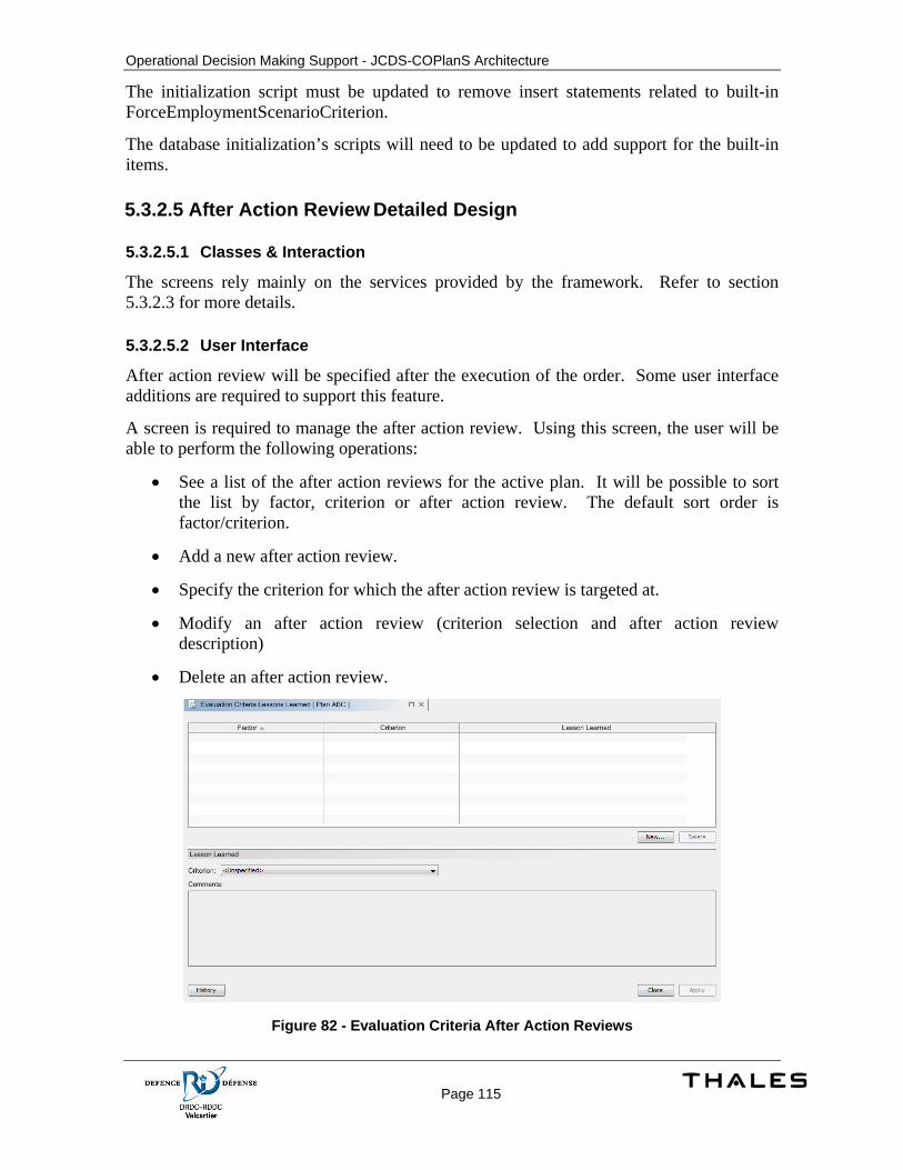
Operational Decision Making Support - JCDS-COPlanS Architecture
Page 115
The initialization script must be updated to remove insert statements related to built-in ForceEmploymentScenarioCriterion.
The database initialization’s scripts will need to be updated to add support for the built-in items.
5.3.2.5 After Action Review Detailed Design
5.3.2.5.1 Classes & Interaction
The screens rely mainly on the services provided by the framework. Refer to section 5.3.2.3 for more details.
5.3.2.5.2 User Interface
After action review will be specified after the execution of the order. Some user interface additions are required to support this feature.
A screen is required to manage the after action review. Using this screen, the user will be able to perform the following operations:
• See a list of the after action reviews for the active plan. It will be possible to sort the list by factor, criterion or after action review. The default sort order is factor/criterion.
• Add a new after action review.
• Specify the criterion for which the after action review is targeted at.
• Modify an after action review (criterion selection and after action review description)
• Delete an after action review.
Figure 82 - Evaluation Criteria After Action Reviews

Operational Decision Making Support - JCDS-COPlanS Architecture
Page 116
Activating the ‘New button’ will create a new instance of AfterActionReview. The new instance will be associated with the active.
The list shows all the after action review associated with the plan (regardless if it is targeted for a specific criterion or not).
The descriptive section at the bottom of the screen contains all the fields for the after action review. This section is updated according to the selection in the list. It contains a field to associate the after action review to a specific criterion. The combo box, for this field, must contain ‘Unspecified’ as possible value (to represent that the after action review is general to the plan). It also contains the list of PlanCriterion associated with the active plan. The text area is used for editing the ‘detailedDescription’ field for the After Action Review.
5.3.2.5.2.1 Actions
A new action is required to access the new screen. The action must be located in the Task Pane group for the Plan Review activity.
Operational Decision Making Support - JCDS-COPlanS Architecture
Page 117
5.3.2.5.2.2 Explorer
A new group ‘After Action Review’ must be added in the explorer model for the Plan Review toolkit. This group is added on the root node. It will contain a node for each after action reviews associated with the plan.
5.3.2.5.2.3 After Action Reviews for a Criterion
It could be interesting to have after action reviews on a criterion for a given criteria set but this feature is not covered by this document.
5.3.2.5.3 Data Requirements
5.3.2.5.3.1 After Action Review
An after action review applies to a specific plan. It can optionally be targeted at a specific plan criterion for the plan.
Table 13 - Evaluation Properties
Property Details New?
detailed description
Yes
planCriterion The plan criterion associated with the after action review
Yes
plan The plan associated with the after action review
Yes
user The user associated with the after action review
Yes
This class and its related table must be added. The metadata must also be provided with the class. No changes are needed to the framework to support this new class.
5.3.2.6 Criteria Selections Detailed Design
5.3.2.6.1 Classes & Interaction
The screens rely mainly on the services provided by the framework. Refer to section 5.3.2.3 for more details.
5.3.2.6.2 User Interface
Criteria selection must be changed to provide operators with an easier way to select them with consideration for previous operations and plans. The criteria selection is currently performed using a basic approach presenting a list of criteria, an action to select a new criterion from a lookup dialog and an action to delete a criterion from the list.
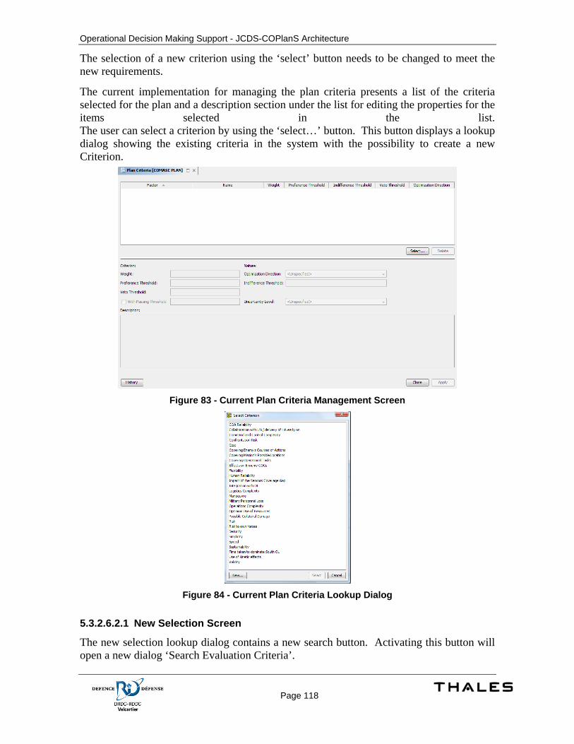
Operational Decision Making Support - JCDS-COPlanS Architecture
Page 118
The selection of a new criterion using the ‘select’ button needs to be changed to meet the new requirements.
The current implementation for managing the plan criteria presents a list of the criteria selected for the plan and a description section under the list for editing the properties for the items selected in the list. The user can select a criterion by using the ‘select…’ button. This button displays a lookup dialog showing the existing criteria in the system with the possibility to create a new Criterion.
Figure 83 - Current Plan Criteria Management Screen
Figure 84 - Current Plan Criteria Lookup Dialog
5.3.2.6.2.1 New Selection Screen
The new selection lookup dialog contains a new search button. Activating this button will open a new dialog ‘Search Evaluation Criteria’.
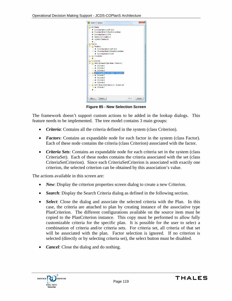
Operational Decision Making Support - JCDS-COPlanS Architecture
Page 119
Figure 85 - New Selection Screen
The framework doesn’t support custom actions to be added in the lookup dialogs. This feature needs to be implemented. The tree model contains 3 main groups:
• Criteria: Contains all the criteria defined in the system (class Criterion).
• Factors: Contains an expandable node for each factor in the system (class Factor). Each of these node contains the criteria (class Criterion) associated with the factor.
• Criteria Sets: Contains an expandable node for each criteria set in the system (class CriteriaSet). Each of these nodes contains the criteria associated with the set (class CriteriaSetCriterion). Since each CriteriaSetCriterion is associated with exactly one criterion, the selected criterion can be obtained by this association’s value.
The actions available in this screen are:
• New: Display the criterion properties screen dialog to create a new Criterion.
• Search: Display the Search Criteria dialog as defined in the following section.
• Select: Close the dialog and associate the selected criteria with the Plan. In this case, the criteria are attached to plan by creating instance of the associative type PlanCriterion. The different configurations available on the source item must be copied to the PlanCriterion instance. This copy must be performed to allow fully customizable criteria for the specific plan. It is possible for the user to select a combination of criteria and/or criteria sets. For criteria set, all criteria of that set will be associated with the plan. Factor selection is ignored. If no criterion is selected (directly or by selecting criteria set), the select button must be disabled.
• Cancel: Close the dialog and do nothing.

Operational Decision Making Support - JCDS-COPlanS Architecture
Page 120
5.3.2.6.3 Data Requirements
5.3.2.6.3.1 Plan
Table 14 - Plan Properties
Property Details New?
forceEmploymentScenario The scenario associated to the plan No
operation The operation associated with the plan
No
5.3.2.6.3.2 Operation
Table 15 - Operation Properties
Property Details New?
operationCategory The Operation category associated with the operation
Yes
The database creation scripts will need to be updated to add the new column and foreign key for the relation defined with Operation Category.
The java class and its metadata specification will need to be updated to support the new association with Operation Category.
5.3.2.6.3.3 Plan Criterion
A plan criterion refines a criterion for a given plan’s context. It defines properties that can be configured for a specific plan.
Table 16 - Plan Criterion Properties
Property Details New?
name No
weight No
indifferenceThreshold No
preferenceThreshold No
vetoThreshold No
optimizationDirection No
plan The plan associated with the plan criterion
No
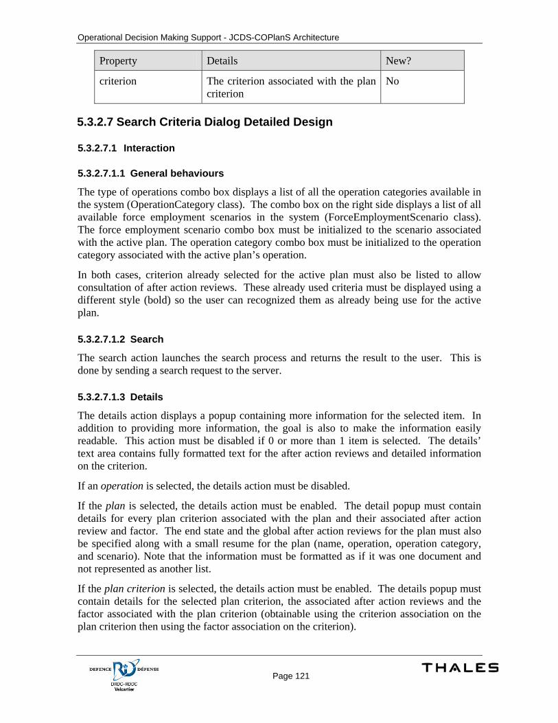
Operational Decision Making Support - JCDS-COPlanS Architecture
Page 121
Property Details New?
criterion The criterion associated with the plan criterion
No
5.3.2.7 Search Criteria Dialog Detailed Design
5.3.2.7.1 Interaction
5.3.2.7.1.1 General behaviours
The type of operations combo box displays a list of all the operation categories available in the system (OperationCategory class). The combo box on the right side displays a list of all available force employment scenarios in the system (ForceEmploymentScenario class). The force employment scenario combo box must be initialized to the scenario associated with the active plan. The operation category combo box must be initialized to the operation category associated with the active plan’s operation.
In both cases, criterion already selected for the active plan must also be listed to allow consultation of after action reviews. These already used criteria must be displayed using a different style (bold) so the user can recognized them as already being use for the active plan.
5.3.2.7.1.2 Search
The search action launches the search process and returns the result to the user. This is done by sending a search request to the server.
5.3.2.7.1.3 Details
The details action displays a popup containing more information for the selected item. In addition to providing more information, the goal is also to make the information easily readable. This action must be disabled if 0 or more than 1 item is selected. The details’ text area contains fully formatted text for the after action reviews and detailed information on the criterion.
If an operation is selected, the details action must be disabled.
If the plan is selected, the details action must be enabled. The detail popup must contain details for every plan criterion associated with the plan and their associated after action review and factor. The end state and the global after action reviews for the plan must also be specified along with a small resume for the plan (name, operation, operation category, and scenario). Note that the information must be formatted as if it was one document and not represented as another list.
If the plan criterion is selected, the details action must be enabled. The details popup must contain details for the selected plan criterion, the associated after action reviews and the factor associated with the plan criterion (obtainable using the criterion association on the plan criterion then using the factor association on the criterion).
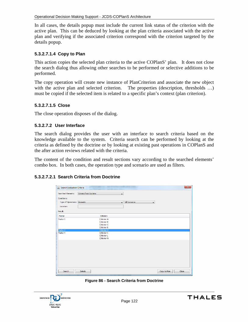
Operational Decision Making Support - JCDS-COPlanS Architecture
Page 122
In all cases, the details popup must include the current link status of the criterion with the active plan. This can be deduced by looking at the plan criteria associated with the active plan and verifying if the associated criterion correspond with the criterion targeted by the details popup.
5.3.2.7.1.4 Copy to Plan
This action copies the selected plan criteria to the active COPlanS’ plan. It does not close the search dialog thus allowing other searches to be performed or selective additions to be performed.
The copy operation will create new instance of PlanCriterion and associate the new object with the active plan and selected criterion. The properties (description, thresholds …) must be copied if the selected item is related to a specific plan’s context (plan criterion).
5.3.2.7.1.5 Close
The close operation disposes of the dialog.
5.3.2.7.2 User Interface
The search dialog provides the user with an interface to search criteria based on the knowledge available to the system. Criteria search can be performed by looking at the criteria as defined by the doctrine or by looking at existing past operations in COPlanS and the after action reviews related with the criteria.
The content of the condition and result sections vary according to the searched elements’ combo box. In both cases, the operation type and scenario are used as filters.
5.3.2.7.2.1 Search Criteria from Doctrine
Figure 86 - Search Criteria from Doctrine
Operational Decision Making Support - JCDS-COPlanS Architecture
Page 123
5.3.2.7.2.2 Filters
Filters can be selected for the operation categories and the force employment scenarios. The system must display pre-defined criteria according to the conditions specified. Pre-defined criteria are defined by Criteria Sets. The search algorithm will look for Criteria for which at least one associated CriteriaSetCriterion is part of a CriteriaSet associated with the selected OperationCategory and/or with the selected ForceEmploymentScenario. Filtering on the OperationCategory is ignored if ‘All Categories’ is selected. Filtering on the ForceEmploymentScenario is ignored if ‘All Force Employment Scenario’ is selected. If both ‘All Categories’ and ‘All Force Employment Scenario’ are selected then both filtering are ignored and the result should be a list of all the criteria in the system.
The location filter does not apply to the doctrine search and its text field must be disabled.
5.3.2.7.2.3 Results
The result displays a table containing a row for each criterion matching both filters. The table contains two columns: the factor associated with the criterion and the criterion name.
The default sort order is the factor.
5.3.2.7.2.4 Search Criteria from Similar Operations
Figure 87 - Search Criteria from Similar Operations
5.3.2.7.2.5 Filters
Filters can be selected for operation categories and the force employment scenarios. When an operation category is selected, the search must be performed on the plans for which the parent operation is associated with selected operation category. When a force employment scenario is selected, the search must be performed on the plans associated with the force
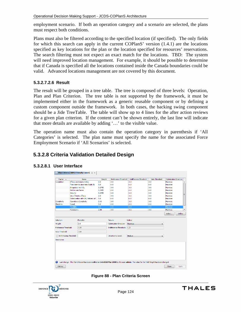
Operational Decision Making Support - JCDS-COPlanS Architecture
Page 124
employment scenario. If both an operation category and a scenario are selected, the plans must respect both conditions.
Plans must also be filtered according to the specified location (if specified). The only fields for which this search can apply in the current COPlanS’ version (1.4.1) are the locations specified as key locations for the plan or the location specified for resources’ reservations. The search filtering must not expect an exact match for the locations. TBD: The system will need improved location management. For example, it should be possible to determine that if Canada is specified all the locations contained inside the Canada boundaries could be valid. Advanced locations management are not covered by this document.
5.3.2.7.2.6 Result
The result will be grouped in a tree table. The tree is composed of three levels: Operation, Plan and Plan Criterion. The tree table is not supported by the framework, it must be implemented either in the framework as a generic reusable component or by defining a custom component outside the framework. In both cases, the backing swing component should be a Jide TreeTable. The table will show up to 4 lines for the after action reviews for a given plan criterion. If the content can’t be shown entirely, the last line will indicate that more details are available by adding ‘…’ to the visible value.
The operation name must also contain the operation category in parenthesis if ‘All Categories’ is selected. The plan name must specify the name for the associated Force Employment Scenario if ‘All Scenarios’ is selected.
5.3.2.8 Criteria Validation Detailed Design
5.3.2.8.1 User Interface
Figure 88 - Plan Criteria Screen
Operational Decision Making Support - JCDS-COPlanS Architecture
Page 125
Validation of criteria is performed by verifying each plan criterion against all the other selected plan criteria. The validation is performed by checking the rules defined by the CriterionRule instances associated with the selected criteria.
When the user selects criteria to add by using the search criteria feature, a message is displayed to indicate a conflict if a rule is violated.
Figure 89 - Rules Validation
5.3.2.8.2 Data Requirements
5.3.2.8.2.1 Criterion Rule
A criterion rule is defined to create relation between 2 criteria. The rule can be inclusive or exclusive. Inclusive rules enforce that 2 criteria must both be used or not used for a given plan. Exclusive rules specify that 2 criteria are not compatible with each other.
Table 17 - Criterion Rule Properties
Property Details New?
name Yes
criterion1 The first criterion implied in the rule Yes
criterion2 The second criterion implied in the rule Yes
ruleType Domain value defining the kind or rule (inclusive, exclusive, …)
Yes
5.3.2.8.3 Process Specification
The database initialization script must be updated with rules creation for built in criteria.
5.3.2.9 COA Viability Detailed Design
5.3.2.9.1 Classes & Interaction
The screens rely mainly on the services provided by the framework. Refer to section 5.3.2.3 for more details.
5.3.2.9.2 User Interface
Operational Decision Making Support - JCDS-COPlanS Architecture
Page 126
Figure 90 - COA Viability
This screen must be created. The framework’s screen components are used to ensure that the history is available (i.e. user x modified the field y on date z). The screen is configured by using the COA specified by the existing COA selector. Note: Only the COAs associated with the affiliation ‘Own’ are available for this screen. The checkboxes are initialized based on the selected COA. If the user uses the button OK, the changes are saved and the dialog closed. If the user uses the ‘Cancel’ button, the dialog is closed and no changes are saved.
5.3.2.9.2.1 Actions
A new action ‘COA Viability’ must be created and added before the ‘End Activity (or assignment)’ action in the COA Development task pane group. The action will display the new screen as a standard screen in the workspace.
5.3.2.9.3 Data Requirements
5.3.2.9.3.1 COA
A new table is required for storing the viabilities for the COAs.
Table 18 – COAViability Properties
Property Details New?
coa The COA to which the viability applies Yes
viable Boolean Yes
acceptedAt DateTime Yes
acceptedBy The user who marked the viability as viable.
Yes

Operational Decision Making Support - JCDS-COPlanS Architecture
Page 127
Property Details New?
internalID Number Yes
The class and the corresponding metadata and table creation script must be updated to add the new fields and class.
The internal ID is used to identify which viability is represented by this instance.
5.3.2.9.4 Process Specification
One entry is created by the triggers (at COA creation) for all pre-defined viability (suitable, feasible, acceptable, exclusive and complete).
Operational Decision Making Support - JCDS-COPlanS Architecture
Page 128
5.4 COA Analysis and Decision Matrixes
5.4.1 Concept of Execution The COA Analysis and Decision Matrix are grids used to compare COAs upon criteria of evaluation. Those grids allow identification of strengths and weaknesses of each COA. The identified weaknesses can help planners to correct their COAs. Mainly, the aim of them is to identify the best scenario (COA) to perform the mission.
COA Analysis is the matrix where a COA is challenged in opposing it to developed adversary COAs. Normally, the most probable and the worst case scenarios are developed as Enemy (or adversary) COAs. For each evaluation criteria, the COA is evaluated in opposing to adversary COAs.
Decision Matrix is the grid where COAs are compared between them to allow the selection of the best COA to perform the mission. Decision Matrix evaluates strength and weaknesses of COAs upon each criterion. The evaluation may also be made in defining a score of each COA upon each criterion. Using evaluations given to each criterion and considering the level of importance of each criterion in the decision, a COA can be identified to become the plan to follow for achieving the mission.
5.4.2 Design Description
5.4.2.1 COA Analysis and Decision Matrixes Screen Detailed Design
5.4.2.1.1 Classes
The screens rely mainly on the services provided by the framework. Refer to section 5.3.2.3 for more details.
The plan criteria screen is a rearrangement from existing components.
A specialized class extending ListTable is required to support the grid defined for the Decision Matrix screen. It is required to support dynamic column creation for each COA and to simulate row headers behaviors (used to display criteria and weight). It is also required to create specialized renderer components for the table in order to display multi-lines html formatted text.
5.4.2.1.2 User Interface
5.4.2.1.2.1 Plan Criteria
Plan Criteria, Fine Tune Tradeoffs, and Fine Tune Criteria Manually screens are used to define criteria and their weight. These screens contain similar information but present different ways to set them. In consolidating all configuration options in one place, the screen could provide different modes for fine tuning.
By consolidating this screen, the developer has to ensure that all components can exchange information.
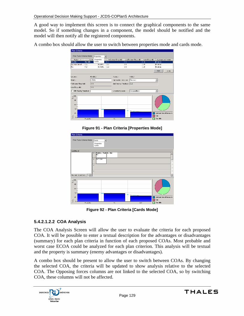
Operational Decision Making Support - JCDS-COPlanS Architecture
Page 129
A good way to implement this screen is to connect the graphical components to the same model. So if something changes in a component, the model should be notified and the model will then notify all the registered components.
A combo box should allow the user to switch between properties mode and cards mode. Plan Criteria
PropertiesFine Tune Criteria Mode
PropertiesCards
Add
Figure 91 - Plan Criteria [Properties Mode] Plan Criteria
CardsFine Tune Criteria Mode
PropertiesCards
Figure 92 - Plan Criteria [Cards Mode]
5.4.2.1.2.2 COA Analysis
The COA Analysis Screen will allow the user to evaluate the criteria for each proposed COA. It will be possible to enter a textual description for the advantages or disadvantages (summary) for each plan criteria in function of each proposed COAs. Most probable and worst case ECOA could be analyzed for each plan criterion. This analysis will be textual and the property is summary (enemy advantages or disadvantages).
A combo box should be present to allow the user to switch between COAs. By changing the selected COA, the criteria will be updated to show analysis relative to the selected COA. The Opposing forces columns are not linked to the selected COA, so by switching COA, these columns will not be affected.
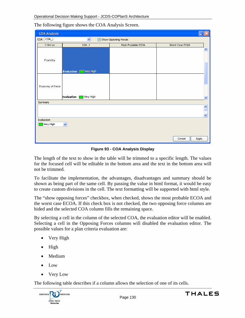
Operational Decision Making Support - JCDS-COPlanS Architecture
Page 130
The following figure shows the COA Analysis Screen.
Figure 93 - COA Analysis Display
The length of the text to show in the table will be trimmed to a specific length. The values for the focused cell will be editable in the bottom area and the text in the bottom area will not be trimmed.
To facilitate the implementation, the advantages, disadvantages and summary should be shown as being part of the same cell. By passing the value in html format, it would be easy to create custom divisions in the cell. The text formatting will be supported with html style.
The “show opposing forces” checkbox, when checked, shows the most probable ECOA and the worst case ECOA. If this check box is not checked, the two opposing force columns are hided and the selected COA column fills the remaining space.
By selecting a cell in the column of the selected COA, the evaluation editor will be enabled. Selecting a cell in the Opposing Forces columns will disabled the evaluation editor. The possible values for a plan criteria evaluation are:
• Very High
• High
• Medium
• Low
• Very Low
The following table describes if a column allows the selection of one of its cells.
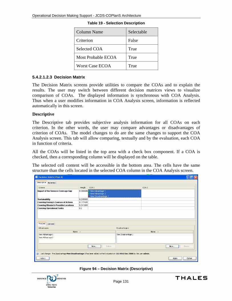
Operational Decision Making Support - JCDS-COPlanS Architecture
Page 131
Table 19 - Selection Description
Column Name Selectable
Criterion False
Selected COA True
Most Probable ECOA True
Worst Case ECOA True
5.4.2.1.2.3 Decision Matrix
The Decision Matrix screens provide utilities to compare the COAs and to explain the results. The user may switch between different decision matrices views to visualize comparison of COAs. The displayed information is synchronous with COA Analysis. Thus when a user modifies information in COA Analysis screen, information is reflected automatically in this screen.
Descriptive
The Descriptive tab provides subjective analysis information for all COAs on each criterion. In the other words, the user may compare advantages or disadvantages of criterion of COAs. The model changes to do are the same changes to support the COA Analysis screen. This tab will allow comparing, textually and by the evaluation, each COA in function of criteria.
All the COAs will be listed in the top area with a check box component. If a COA is checked, then a corresponding column will be displayed on the table.
The selected cell content will be accessible in the bottom area. The cells have the same structure than the cells located in the selected COA column in the COA Analysis screen.
Figure 94 – Decision Matrix (Descriptive)
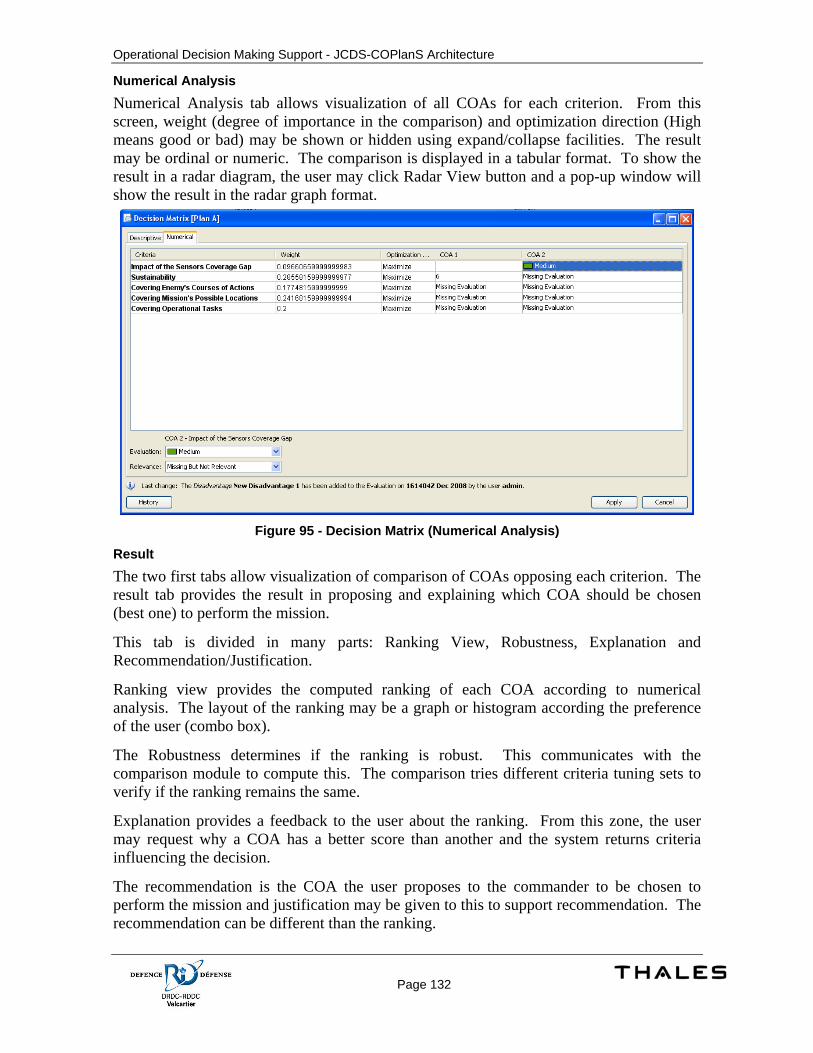
Operational Decision Making Support - JCDS-COPlanS Architecture
Page 132
Numerical Analysis Numerical Analysis tab allows visualization of all COAs for each criterion. From this screen, weight (degree of importance in the comparison) and optimization direction (High means good or bad) may be shown or hidden using expand/collapse facilities. The result may be ordinal or numeric. The comparison is displayed in a tabular format. To show the result in a radar diagram, the user may click Radar View button and a pop-up window will show the result in the radar graph format.
Figure 95 - Decision Matrix (Numerical Analysis)
Result The two first tabs allow visualization of comparison of COAs opposing each criterion. The result tab provides the result in proposing and explaining which COA should be chosen (best one) to perform the mission.
This tab is divided in many parts: Ranking View, Robustness, Explanation and Recommendation/Justification.
Ranking view provides the computed ranking of each COA according to numerical analysis. The layout of the ranking may be a graph or histogram according the preference of the user (combo box).
The Robustness determines if the ranking is robust. This communicates with the comparison module to compute this. The comparison tries different criteria tuning sets to verify if the ranking remains the same.
Explanation provides a feedback to the user about the ranking. From this zone, the user may request why a COA has a better score than another and the system returns criteria influencing the decision.
The recommendation is the COA the user proposes to the commander to be chosen to perform the mission and justification may be given to this to support recommendation. The recommendation can be different than the ranking.
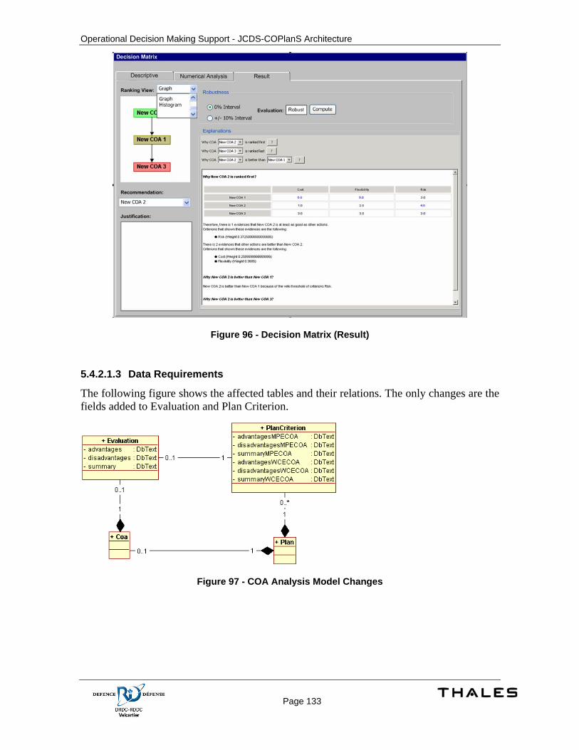
Operational Decision Making Support - JCDS-COPlanS Architecture
Page 133
Figure 96 - Decision Matrix (Result)
5.4.2.1.3 Data Requirements
The following figure shows the affected tables and their relations. The only changes are the fields added to Evaluation and Plan Criterion.
Figure 97 - COA Analysis Model Changes
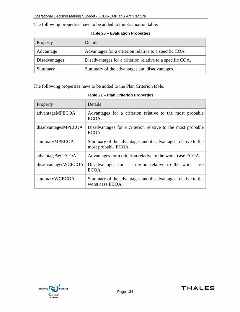
Operational Decision Making Support - JCDS-COPlanS Architecture
Page 134
The following properties have to be added to the Evaluation table.
Table 20 – Evaluation Properties
Property Details
Advantage Advantages for a criterion relative to a specific COA.
Disadvantages Disadvantages for a criterion relative to a specific COA.
Summary Summary of the advantages and disadvantages.
The following properties have to be added to the Plan Criterion table.
Table 21 – Plan Criterion Properties
Property Details
advantageMPECOA Advantages for a criterion relative to the most probable ECOA.
disadvantagesMPECOA Disadvantages for a criterion relative to the most probable ECOA.
summaryMPECOA Summary of the advantages and disadvantages relative to the most probable ECOA.
advantageWCECOA Advantages for a criterion relative to the worst case ECOA.
disadvantagesWCECOA Disadvantages for a criterion relative to the worst case ECOA.
summaryWCECOA Summary of the advantages and disadvantages relative to the worst case ECOA.

Operational Decision Making Support - JCDS-COPlanS Architecture
Page 135
5.5 Plan Management This is the capability to manage Operation Plan (OPLAN) and Contingency Plan (CONPLAN).
5.5.1 Concept of Execution An Operational Plan (OPLAN) is created to address a specific situation considering friendly and adversary forces, terrain and other elements. Those kinds of plans are developed in a stressed environment where time is a major constraint. Decision must be taken quickly and some idea cannot be explored deeply. Operational Plans are used in the operational theatre.
To take best decisions and do best actions when a complex situations occur, time is required. Unfortunately, actions to be taken when events happen require a quick reaction. To mitigate the risk making wrong decisions and to prevent a lack of planning, a Contingency Plan (CONPLAN) allows development of a plan for possible situations. This allows planners to define elements of a plan in an unstressed environment. CONPLANs are generally generic because they cannot predict exactly what will be the situation at a specific time and location. When a situation happens, the CONPLAN is used as the starting point for the OPLAN.
CONPLANs are developed to anticipate generic possible situations. Example: a terrorist attack on the Canadian territory. This kind of CONPLAN does not address a specific location. Thus, elements must be general like defining tasks to join local authorities, secure zone of danger, etc. Some CONPLANs can be more specific to address possible situations having a high level of risk. Example: An evacuation plan of Vancouver in the case of a Tsunami, or a terrorist attack during Olympic Games, etc. In both cases, a CONPLAN is used to create an OPLAN.
When an event happens, the planner (probably Chief-Of-Staff or J5) verifies if a CONPLAN exists for this situation. If yes, an OPLAN is created by copying elements of the corresponding CONPLAN; otherwise an OPLAN is created from scratch. The OPLAN is developed and becomes the order to be executed to address issues related to the actual events.
5.5.2 Design Description
5.5.2.1 Interface Description When the user creates a plan (either a CONPLAN or an OPLAN) from an existing CONPLAN, the elements contained in the CONPLAN are copied into the newly create plan. This is done by using a function called the PlanCopier.
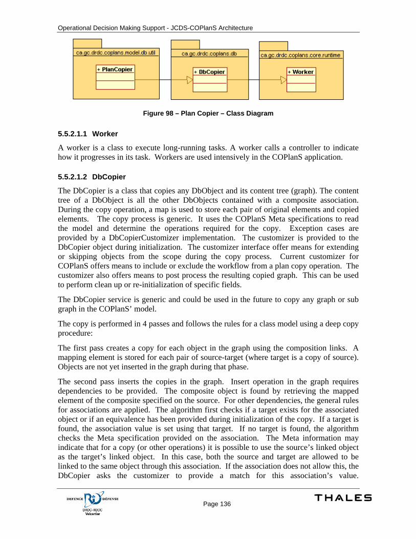
Operational Decision Making Support - JCDS-COPlanS Architecture
Page 136
Figure 98 – Plan Copier – Class Diagram
5.5.2.1.1 Worker
A worker is a class to execute long-running tasks. A worker calls a controller to indicate how it progresses in its task. Workers are used intensively in the COPlanS application.
5.5.2.1.2 DbCopier
The DbCopier is a class that copies any DbObject and its content tree (graph). The content tree of a DbObject is all the other DbObjects contained with a composite association. During the copy operation, a map is used to store each pair of original elements and copied elements. The copy process is generic. It uses the COPlanS Meta specifications to read the model and determine the operations required for the copy. Exception cases are provided by a DbCopierCustomizer implementation. The customizer is provided to the DbCopier object during initialization. The customizer interface offer means for extending or skipping objects from the scope during the copy process. Current customizer for COPlanS offers means to include or exclude the workflow from a plan copy operation. The customizer also offers means to post process the resulting copied graph. This can be used to perform clean up or re-initialization of specific fields.
The DbCopier service is generic and could be used in the future to copy any graph or sub graph in the COPlanS’ model.
The copy is performed in 4 passes and follows the rules for a class model using a deep copy procedure:
The first pass creates a copy for each object in the graph using the composition links. A mapping element is stored for each pair of source-target (where target is a copy of source). Objects are not yet inserted in the graph during that phase.
The second pass inserts the copies in the graph. Insert operation in the graph requires dependencies to be provided. The composite object is found by retrieving the mapped element of the composite specified on the source. For other dependencies, the general rules for associations are applied. The algorithm first checks if a target exists for the associated object or if an equivalence has been provided during initialization of the copy. If a target is found, the association value is set using that target. If no target is found, the algorithm checks the Meta specification provided on the association. The Meta information may indicate that for a copy (or other operations) it is possible to use the source’s linked object as the target’s linked object. In this case, both the source and target are allowed to be linked to the same object through this association. If the association does not allow this, the DbCopier asks the customizer to provide a match for this association’s value.
Operational Decision Making Support - JCDS-COPlanS Architecture
Page 137
If the customizer does not provide a value, the DbCopier checks if it is possible to nullify the association’s value. If not, an exception is thrown since it is not possible to resolve this association.
The third pass copies all non-associative properties on the objects, including blob (binary large object) objects.
The fourth pass copies all other associative properties on the objects following the same rules for associations as specified for the first phase.
5.5.2.1.3 PlanCopier
This class copies plan instances. It uses the service DbCopier and provides a DbCopierCustomizer. PlanCopier includes what it is specific the copy of plans. By default, DbCopier copy the DbObjects associated with a composition link, but does not copy DbObjects associated with a regular association link. In the case of plans, the workflows are optionally ignored (even if there are associated to a plan with a composition link), and the folders, briefs, warning orders and other documents are copied (even if they are associated to a plan with a regular association link). The copy is extended to include additional objects in the copy (outside of the normal composition graph).
The worker thread class is responsible to begin and commit the Db transaction, so the client doesn't have to begin a transaction before calling start (). It also creates the PlanCopier instance and invokes the copyPlan() method.
The following code shows how client code can use the PlanCopier class:
// in this example, copy of the plan will be placed in the same
// campaign as the original plan
CampaignPlan parent = originalPlan.getComposite();
// if originalPlan's name is "Evacuation",
// the newly created plan will be named "Copy of Evacuation"
String newPlanName = "Copy of " + originalPlan.getName();
// create a controller (copy of plans is a
// long-running operation)
Controller controller = new NullController();
// launch the operation on the controller. This will start the worker thread.
controller.start(copier);
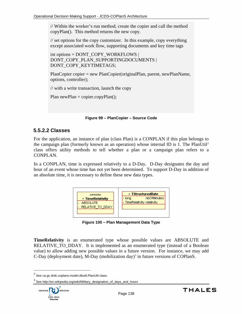
Operational Decision Making Support - JCDS-COPlanS Architecture
Page 138
// Within the worker’s run method, create the copier and call the method copyPlan(). This method returns the new copy.
// set options for the copy customizer. In this example, copy everything except associated work flow, supporting documents and key time tags
int options = DONT_COPY_WORKFLOWS | DONT_COPY_PLAN_SUPPORTINGDOCUMENTS | DONT_COPY_KEYTIMETAGS;
PlanCopier copier = new PlanCopier(originalPlan, parent, newPlanName, options, controller);
// with a write transaction, launch the copy
Plan newPlan = copier.copyPlan();
Figure 99 – PlanCopier – Source Code
5.5.2.2 Classes For the application, an instance of plan (class Plan) is a CONPLAN if this plan belongs to the campaign plan (formerly known as an operation) whose internal ID is 1. The PlanUtil2 class offers utility methods to tell whether a plan or a campaign plan refers to a CONPLAN.
In a CONPLAN, time is expressed relatively to a D-Day. D-Day designates the day and hour of an event whose time has not yet been determined. To support D-Day in addition of an absolute time, it is necessary to define these new data types.
Figure 100 – Plan Management Data Type
TimeRelativity is an enumerated type whose possible values are ABSOLUTE and RELATIVE_TO_DDAY. It is implemented as an enumerated type (instead of a Boolean value) to allow adding new possible values in a future version. For instance, we may add C-Day (deployment date), M-Day (mobilization day)3 in future versions of COPlanS.
2 See ca.gc.drdc.coplans.model.dbutil.PlanUtil class. 3 See http://en.wikipedia.org/wiki/Military_designation_of_days_and_hours
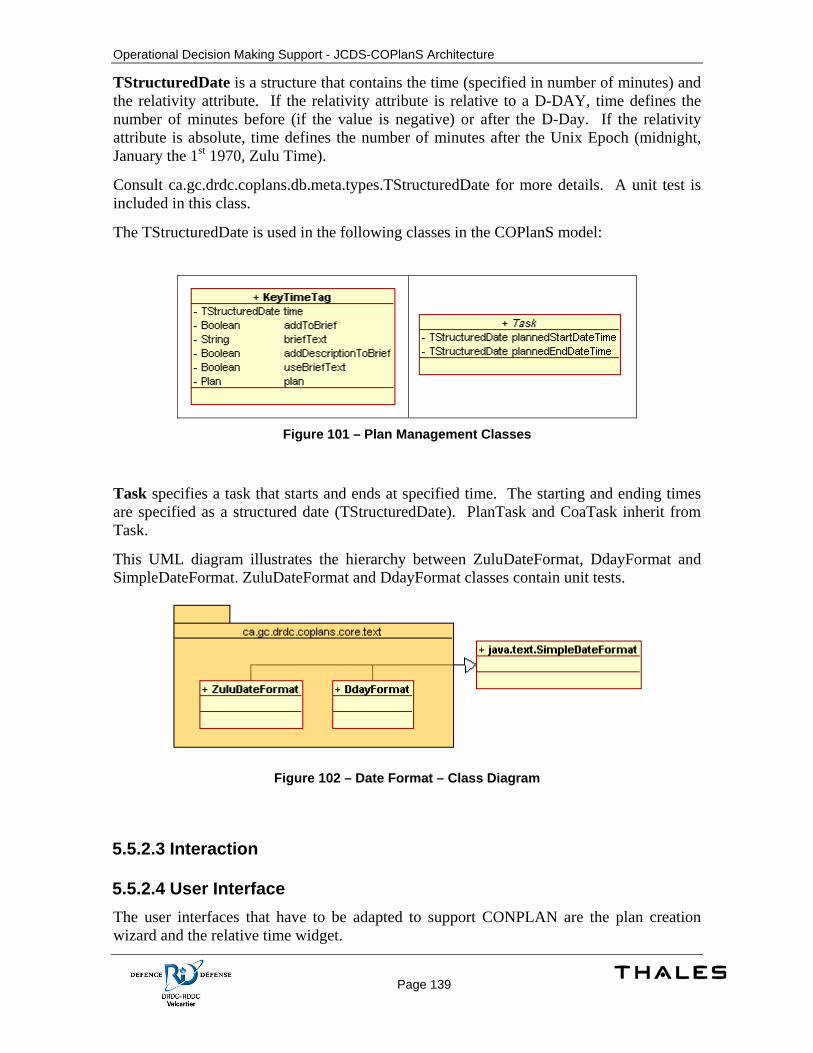
Operational Decision Making Support - JCDS-COPlanS Architecture
Page 139
TStructuredDate is a structure that contains the time (specified in number of minutes) and the relativity attribute. If the relativity attribute is relative to a D-DAY, time defines the number of minutes before (if the value is negative) or after the D-Day. If the relativity attribute is absolute, time defines the number of minutes after the Unix Epoch (midnight, January the 1st 1970, Zulu Time).
Consult ca.gc.drdc.coplans.db.meta.types.TStructuredDate for more details. A unit test is included in this class.
The TStructuredDate is used in the following classes in the COPlanS model:
Figure 101 – Plan Management Classes
Task specifies a task that starts and ends at specified time. The starting and ending times are specified as a structured date (TStructuredDate). PlanTask and CoaTask inherit from Task.
This UML diagram illustrates the hierarchy between ZuluDateFormat, DdayFormat and SimpleDateFormat. ZuluDateFormat and DdayFormat classes contain unit tests.
Figure 102 – Date Format – Class Diagram
5.5.2.3 Interaction
5.5.2.4 User Interface The user interfaces that have to be adapted to support CONPLAN are the plan creation wizard and the relative time widget.
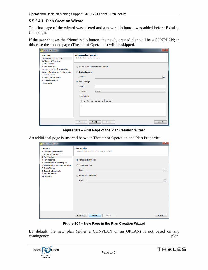
Operational Decision Making Support - JCDS-COPlanS Architecture
Page 140
5.5.2.4.1 Plan Creation Wizard
The first page of the wizard was altered and a new radio button was added before Existing Campaign.
If the user chooses the ‘None’ radio button, the newly created plan will be a CONPLAN; in this case the second page (Theater of Operation) will be skipped.
Figure 103 – First Page of the Plan Creation Wizard
An additional page is inserted between Theater of Operation and Plan Properties.
Figure 104 – New Page in the Plan Creation Wizard
By default, the new plan (either a CONPLAN or an OPLAN) is not based on any contingency plan.
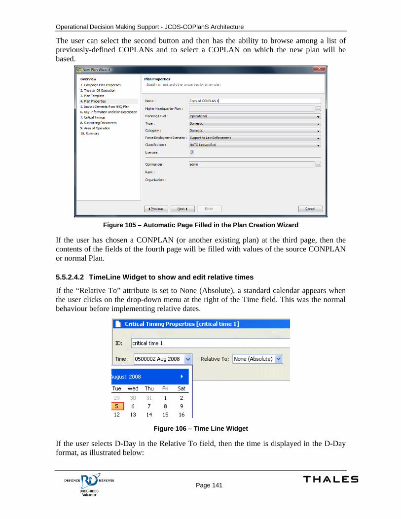
Operational Decision Making Support - JCDS-COPlanS Architecture
Page 141
The user can select the second button and then has the ability to browse among a list of previously-defined COPLANs and to select a COPLAN on which the new plan will be based.
Figure 105 – Automatic Page Filled in the Plan Creation Wizard
If the user has chosen a CONPLAN (or another existing plan) at the third page, then the contents of the fields of the fourth page will be filled with values of the source CONPLAN or normal Plan.
5.5.2.4.2 TimeLine Widget to show and edit relative times
If the “Relative To” attribute is set to None (Absolute), a standard calendar appears when the user clicks on the drop-down menu at the right of the Time field. This was the normal behaviour before implementing relative dates.
Figure 106 – Time Line Widget
If the user selects D-Day in the Relative To field, then the time is displayed in the D-Day format, as illustrated below:
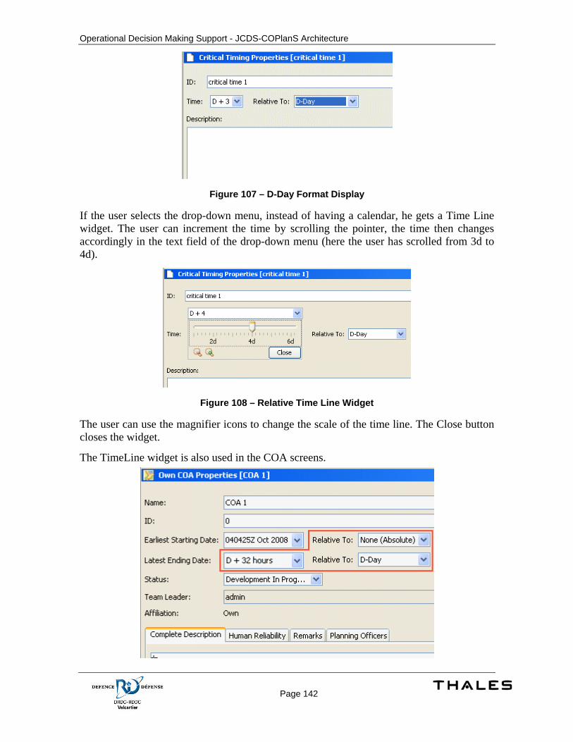
Operational Decision Making Support - JCDS-COPlanS Architecture
Page 142
Figure 107 – D-Day Format Display
If the user selects the drop-down menu, instead of having a calendar, he gets a Time Line widget. The user can increment the time by scrolling the pointer, the time then changes accordingly in the text field of the drop-down menu (here the user has scrolled from 3d to 4d).
Figure 108 – Relative Time Line Widget
The user can use the magnifier icons to change the scale of the time line. The Close button closes the widget.
The TimeLine widget is also used in the COA screens.
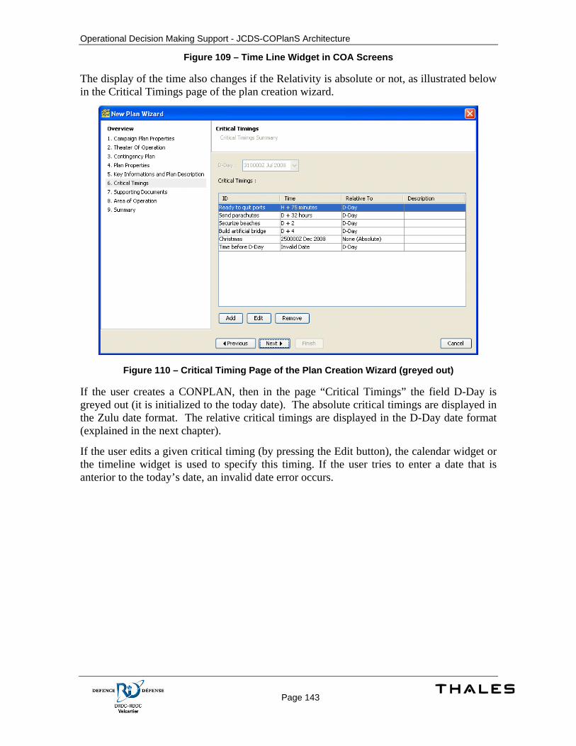
Operational Decision Making Support - JCDS-COPlanS Architecture
Page 143
Figure 109 – Time Line Widget in COA Screens
The display of the time also changes if the Relativity is absolute or not, as illustrated below in the Critical Timings page of the plan creation wizard.
Figure 110 – Critical Timing Page of the Plan Creation Wizard (greyed out)
If the user creates a CONPLAN, then in the page “Critical Timings” the field D-Day is greyed out (it is initialized to the today date). The absolute critical timings are displayed in the Zulu date format. The relative critical timings are displayed in the D-Day date format (explained in the next chapter).
If the user edits a given critical timing (by pressing the Edit button), the calendar widget or the timeline widget is used to specify this timing. If the user tries to enter a date that is anterior to the today’s date, an invalid date error occurs.
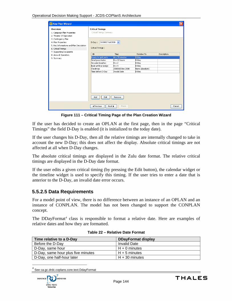
Operational Decision Making Support - JCDS-COPlanS Architecture
Page 144
Figure 111 – Critical Timing Page of the Plan Creation Wizard
If the user has decided to create an OPLAN at the first page, then in the page “Critical Timings” the field D-Day is enabled (it is initialized to the today date).
If the user changes his D-Day, then all the relative timings are internally changed to take in account the new D-Day; this does not affect the display. Absolute critical timings are not affected at all when D-Day changes.
The absolute critical timings are displayed in the Zulu date format. The relative critical timings are displayed in the D-Day date format.
If the user edits a given critical timing (by pressing the Edit button), the calendar widget or the timeline widget is used to specify this timing. If the user tries to enter a date that is anterior to the D-Day, an invalid date error occurs.
5.5.2.5 Data Requirements For a model point of view, there is no difference between an instance of an OPLAN and an instance of CONPLAN. The model has not been changed to support the CONPLAN concept.
The DDayFormat4 class is responsible to format a relative date. Here are examples of relative dates and how they are formatted.
Table 22 – Relative Date Format
Time relative to a D-Day DDayFormat display Before the D-Day Invalid Date D-Day, same hour H + 0 minutes D-Day, same hour plus five minutes H + 5 minutes D-Day, one half-hour later H + 30 minutes
4 See ca.gc.drdc.coplans.core.text.DdayFormat

Operational Decision Making Support - JCDS-COPlanS Architecture
Page 145
Time relative to a D-Day DDayFormat display D-Day, one hour later H + 60 minutes D-Day, less than two hours later H + 119 minutes D-Day, two hours later H + 2 D-Day, same day H + 23 D-Day, the day after D + 24 hours D-Day, two days after D + 2 D-Day, one week later D + 7 D-Day, one month later D + 30
When used in combination with figures, and plus or minus signs, these terms indicate the point of time preceding or following a specific action. Thus, H−3 means 3 hours before H-Hour, and D+3 means 3 days after D-Day. H+75 minutes means H-Hour plus 1 hour and 15 minutes. Source: http://en.wikipedia.org/wiki/D-Day
Figure 112 – Wikipedia Excerpt

Operational Decision Making Support - JCDS-COPlanS Architecture
Page 146
5.6 Risk Management
5.6.1 Concept of Execution The purpose of risk management for CF operations is to effectively identify, analyze, evaluate and control all types of risk. Its key aim is to ensure that significant risks are identified and that appropriate action is taken to minimize these risks, balanced against operational objectives. Risk management functions must be incorporated into the CF OPP in order to support decision makers at all levels.
Risk management is an essential part of the CF OPP that assists decision makers in determining how to reduce or offset risk and to make informed decisions that weigh risks against mission benefits. It is a methodology that assists in the identification of the optimum course of action (COA) and ensures that the implications of residual risks are understood and communicated. Risk management, a commander’s responsibility, must be fully integrated into the planning, preparation, and execution of operations. Risk management consists of risk assessment (threat identification and assessment) and risk mitigation (develop controls, make decisions, implement controls, and supervise and review).
5.6.2 Design Description
5.6.2.1 Threat Detailed Design
5.6.2.1.1 Classes
The risk management screens rely mainly on the services provided by the framework. Refer to section 5.3.2.3 for more details.
Specific renderer and editor components are defined to support the Global Risk and other risk evaluation fields.
A framework component to support hierarchical table is needed and its specific DbModel needs to be implemented. This GUI component extends the hierarchical table defined by JideSoft. The model implementation extends the default model defined by Swings in addition to implement the required methods of DbModel. Refer to section 5.3.2.3 for the class model (blue highlight).
5.6.2.1.2 User Interface
5.6.2.1.2.1 Threats List
The threats list allows the user to see all the threats for the current plan. By using this screen, the user should be able to create a new threat, delete an existing threat or to import a threat form other plans.
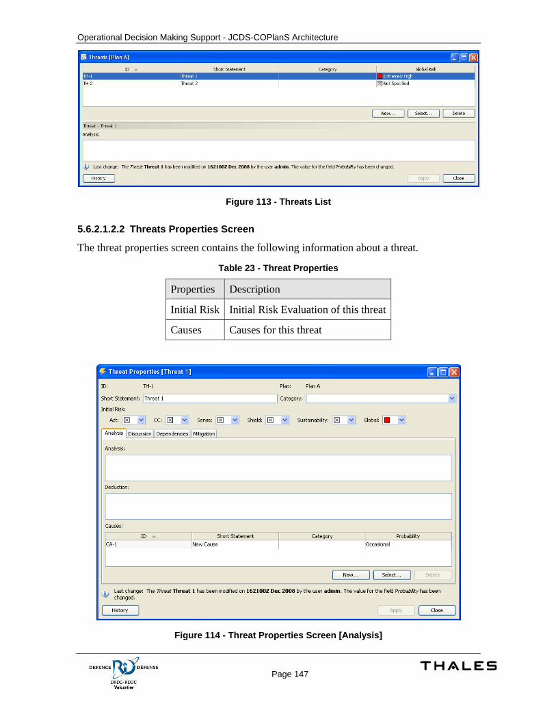
Operational Decision Making Support - JCDS-COPlanS Architecture
Page 147
Figure 113 - Threats List
5.6.2.1.2.2 Threats Properties Screen
The threat properties screen contains the following information about a threat.
Table 23 - Threat Properties
Properties Description
Initial Risk Initial Risk Evaluation of this threat
Causes Causes for this threat
Figure 114 - Threat Properties Screen [Analysis]
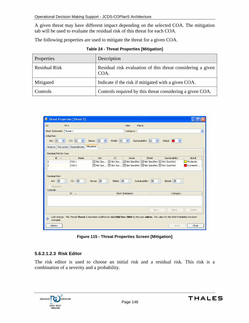
Operational Decision Making Support - JCDS-COPlanS Architecture
Page 148
A given threat may have different impact depending on the selected COA. The mitigation tab will be used to evaluate the residual risk of this threat for each COA.
The following properties are used to mitigate the threat for a given COA.
Table 24 - Threat Properties [Mitigation]
Properties Description
Residual Risk Residual risk evaluation of this threat considering a given COA.
Mitigated Indicate if the risk if mitigated with a given COA.
Controls Controls required by this threat considering a given COA.
Figure 115 - Threat Properties Screen [Mitigation]
5.6.2.1.2.3 Risk Editor
The risk editor is used to choose an initial risk and a residual risk. This risk is a combination of a severity and a probability.
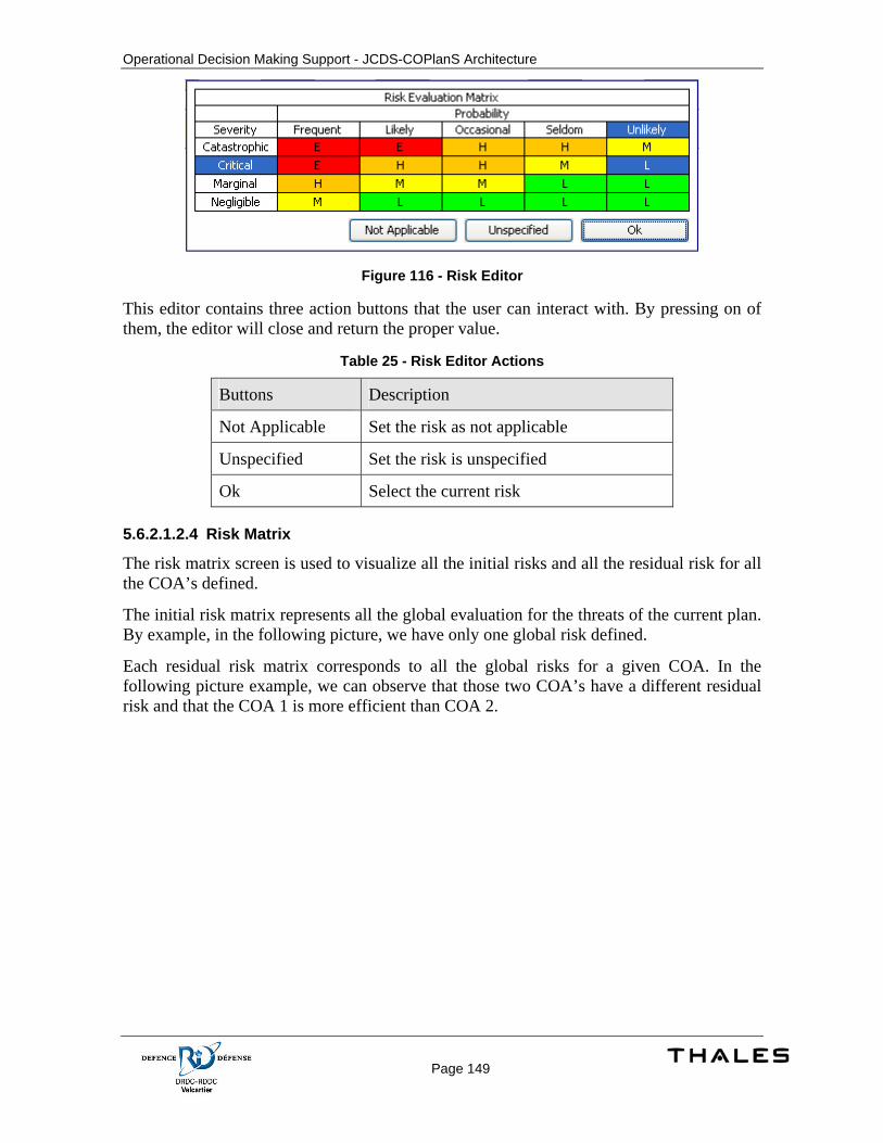
Operational Decision Making Support - JCDS-COPlanS Architecture
Page 149
Figure 116 - Risk Editor
This editor contains three action buttons that the user can interact with. By pressing on of them, the editor will close and return the proper value.
Table 25 - Risk Editor Actions
Buttons Description
Not Applicable Set the risk as not applicable
Unspecified Set the risk is unspecified
Ok Select the current risk
5.6.2.1.2.4 Risk Matrix
The risk matrix screen is used to visualize all the initial risks and all the residual risk for all the COA’s defined.
The initial risk matrix represents all the global evaluation for the threats of the current plan. By example, in the following picture, we have only one global risk defined.
Each residual risk matrix corresponds to all the global risks for a given COA. In the following picture example, we can observe that those two COA’s have a different residual risk and that the COA 1 is more efficient than COA 2.
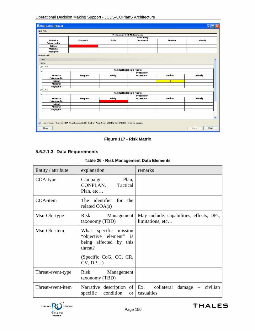
Operational Decision Making Support - JCDS-COPlanS Architecture
Page 150
Figure 117 - Risk Matrix
5.6.2.1.3 Data Requirements
Table 26 - Risk Management Data Elements
Entity / attribute explanation remarks
COA-type Campaign Plan, CONPLAN, Tactical Plan, etc…
COA-item The identifier for the related COA(s)
Msn-Obj-type Risk Management taxonomy (TBD)
May include: capabilities, effects, DPs, limitations, etc…
Msn-Obj-item What specific mission “objective element” is being affected by this threat?
(Specific CoG, CC, CR, CV, DP…)
Threat-event-type Risk Management taxonomy (TBD)
Threat-event-item Narrative description of specific condition or
Ex: collateral damage – civilian casualties
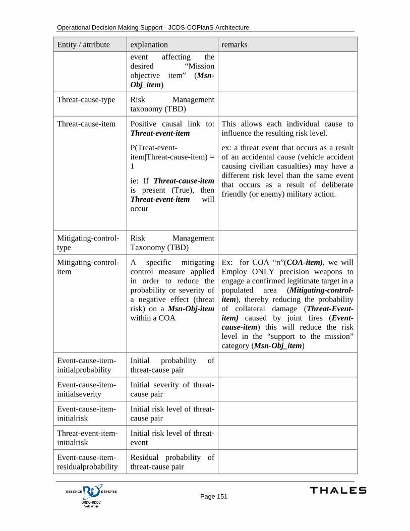
Operational Decision Making Support - JCDS-COPlanS Architecture
Page 151
Entity / attribute explanation remarks event affecting the desired “Mission objective item” (Msn-Obj_item)
Threat-cause-type Risk Management taxonomy (TBD)
Threat-cause-item Positive causal link to: Threat-event-item
P(Treat-event-item|Threat-cause-item) = 1
ie: If Threat-cause-item is present (True), then Threat-event-item will occur
This allows each individual cause to influence the resulting risk level.
ex: a threat event that occurs as a result of an accidental cause (vehicle accident causing civilian casualties) may have a different risk level than the same event that occurs as a result of deliberate friendly (or enemy) military action.
Mitigating-control-type
Risk Management Taxonomy (TBD)
Mitigating-control-item
A specific mitigating control measure applied in order to reduce the probability or severity of a negative effect (threat risk) on a Msn-Obj-item within a COA
Ex: for COA “n”(COA-item), we will Employ ONLY precision weapons to engage a confirmed legitimate target in a populated area (Mitigating-control-item), thereby reducing the probability of collateral damage (Threat-Event-item) caused by joint fires (Event-cause-item) this will reduce the risk level in the “support to the mission” category (Msn-Obj_item)
Event-cause-item-initialprobability
Initial probability of threat-cause pair
Event-cause-item-initialseverity
Initial severity of threat-cause pair
Event-cause-item-initialrisk
Initial risk level of threat-cause pair
Threat-event-item-initialrisk
Initial risk level of threat-event
Event-cause-item-residualprobability
Residual probability of threat-cause pair

Operational Decision Making Support - JCDS-COPlanS Architecture
Page 152
Entity / attribute explanation remarks
Event-cause-item-residualseverity
Residual severity of threat-cause pair
Event-cause-item-residualrisk
Residual risk level of threat-cause pair
Threat-event-item-residualrisk
Residual risk level of threat-event
Operational Decision Making Support - JCDS-COPlanS Architecture
Page 153
5.7 Links with Execution Management Tool EMPA is the system used to monitor and manage orders. Orders are the manifestation of the final approved plans and decisions. Plans are developed with COPlanS and their execution is managed by EMPA. In parallel, JCDS provides an environment to exchange information between these systems. Using the JCDS communication facility, COPlanS’ plans and EMPA’s orders can be synchronized. In the same way, COPlanS produces documents related to developed plans where they can be shared and retrieved from the JCDS document repository.
5.7.1 Concept of Execution COPlanS and EMPA relationship is not limited to a single integration point. Using the JCDS infrastructure, COPlanS and EMPA share various kinds of information. This information is related to plans, documents and maps.
5.7.1.1 Plan synchronization Using COPlanS, the joint operational planning cell develops plans to deal with specific operational situations. When the operational plan is approved by the commander, it is disseminated as an operational order (OpO). The order is executed by the operational forces under command of the Joint Task Force Commander (JTFC) and monitored by the joint operations centre through the EMPA.
As the current situation evolves over time, the conduct of the operation may not conform to the expectations in which it has been initially planned. In monitoring the execution of the operation guided by the operational order, the operations cell will identify and react to discrepancies. Depending on the scope of change between the plan and evolving operational situation, a decision to re-plan the operation may have to be made by the JTFC upon recommendation of the joint operations cell. In this case, the joint planning cell is notified to redo the plan partially or entirely. An issued order will not normally be modified. To amend an order, another order must be issued. The Fragmentary Order (FragO) is used to amend an order. A new Operational Order (OpO) could also be issued to replace an existing order entirely.
The new order/amendment is executed and monitored and may require another re-planning if the situation changes again. This is done until the operation is executed completely.
Operational Decision Making Support - JCDS-COPlanS Architecture
Page 154
sd Execution Management Tool Interaction
EMPACOPlanS
Start P lanning
Develop plan according toOPP
Plan
Execute Order
Operational Order (OpO)
New Situation
Start M ission
Monitor Execution
Initial S ituation
Discrepanciesbetween the orderand the situation
Requ irere-planning
Repl anni ng request
Replanning
Modified Plan
Fragment Order (FragO)
Adapt order executionaccording to the new
situation
Start Replanning
Order Executed
Planning cell
Op Ce ll«flow»
«flow»
«flow»
Approved plan
«flow»
«flow»
Approved Amendment
No
As planned
«flow»
Discrepancies
Yes
«flow»
«flow»
Figure 118 – Execution Management – Activity Diagram
5.7.1.2 Documents sharing COPlanS produces several documents related to planned operations (ex. briefs). The JCDS environment provides the capability to share documents with other applications. In re-using this JCDS document management capability, COPlanS can send its documents on the JCDS repository.
5.7.1.3 Geo-reference reusing COPlans may use any WMS server. JCDS provides a WMS server for all JCDS GIS applications. COPlanS may connect to the same GIS server to handle its information on same maps
5.7.2 Design Description
5.7.2.1 API Detailed Design
5.7.2.1.1 Interface Description
Applications do not communicate together directly. The JCDS infrastructure is based on Service Oriented Architecture (SOA). Information is communicated via requests to an Enterprise Service Bus (ESB).
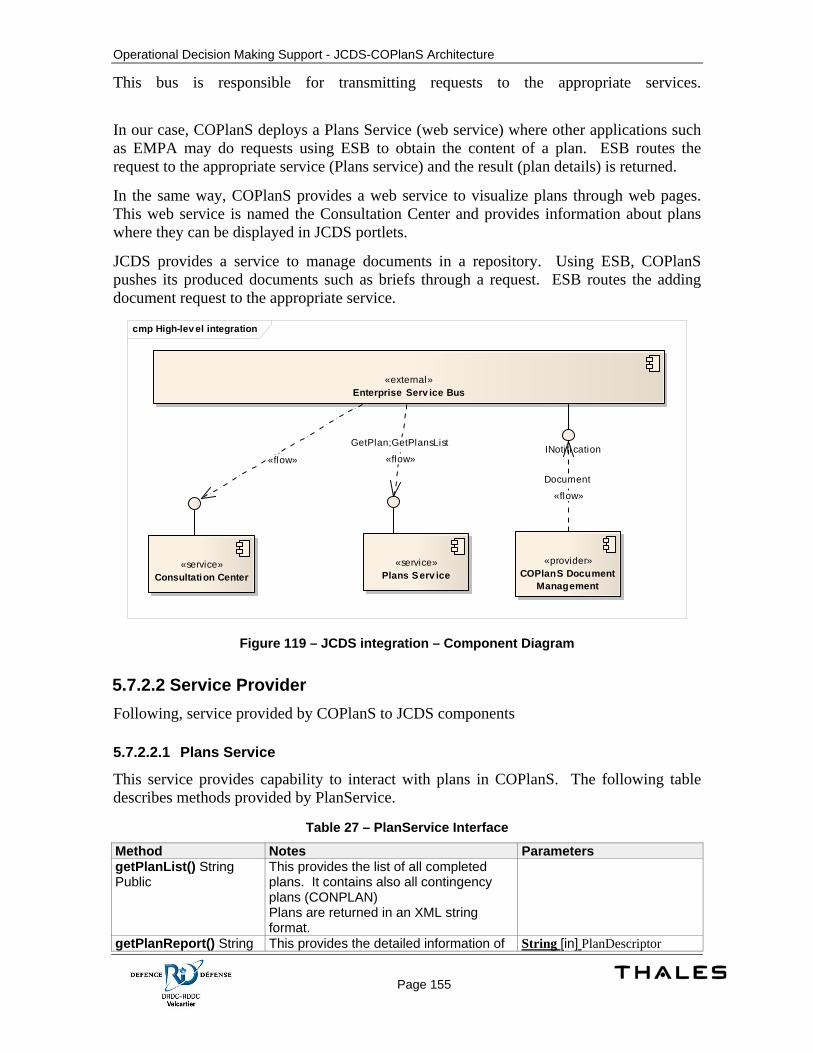
Operational Decision Making Support - JCDS-COPlanS Architecture
Page 155
This bus is responsible for transmitting requests to the appropriate services.
In our case, COPlanS deploys a Plans Service (web service) where other applications such as EMPA may do requests using ESB to obtain the content of a plan. ESB routes the request to the appropriate service (Plans service) and the result (plan details) is returned.
In the same way, COPlanS provides a web service to visualize plans through web pages. This web service is named the Consultation Center and provides information about plans where they can be displayed in JCDS portlets.
JCDS provides a service to manage documents in a repository. Using ESB, COPlanS pushes its produced documents such as briefs through a request. ESB routes the adding document request to the appropriate service.
cmp High-lev el integration
«service»Consultation Center
«service»Plans Serv ice
«provider»COPlanS Document
Management
«external»Enterprise Serv ice Bus
INotifi cation«flow»
GetPlan;GetPlansList
«flow»
Document
«flow»
Figure 119 – JCDS integration – Component Diagram
5.7.2.2 Service Provider Following, service provided by COPlanS to JCDS components
5.7.2.2.1 Plans Service
This service provides capability to interact with plans in COPlanS. The following table describes methods provided by PlanService.
Table 27 – PlanService Interface
Method Notes Parameters getPlanList() String Public
This provides the list of all completed plans. It contains also all contingency plans (CONPLAN) Plans are returned in an XML string format.
getPlanReport() String This provides the detailed information of String [in] PlanDescriptor
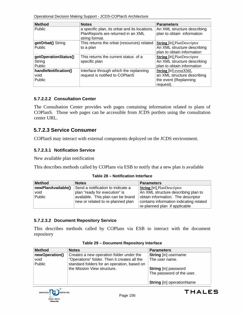
Operational Decision Making Support - JCDS-COPlanS Architecture
Page 156
Method Notes Parameters Public a specific plan, its orbat and its locations.
PlanReports are returned in an XML string format.
An XML structure describing plan to obtain information
getOrbat() String Public
This returns the orbat (resources) related to a plan
String [in] PlanDescriptor An XML structure describing plan to obtain information
getOperationStatus() String Public
This returns the current status of a specific plan
String [in] PlanDescriptor An XML structure describing plan to obtain information
handleNotification() void Public
Interface through which the replanning request is notified to COPlanS
String [in] eventXML an XML structure describing the event (Replanning request).
5.7.2.2.2 Consultation Center
The Consultation Center provides web pages containing information related to plans of COPlanS. Those web pages can be accessible from JCDS portlets using the consultation center URL.
5.7.2.3 Service Consumer COPlanS may interact with external components deployed on the JCDS environment.
5.7.2.3.1 Notification Service
New available plan notification
This describes methods called by COPlans via ESB to notify that a new plan is available
Table 28 – Notification Interface
Method Notes Parameters newPlanAvailable() void Public
Send a notification to indicate a plan “ready for execution” is available. This plan can be brand new or related to re-planned plan
String [in] PlanDescriptor An XML structure describing plan to obtain information. The descriptor contains information indicating related re-planned plan if applicable
5.7.2.3.2 Document Repository Service
This describes methods called by COPlans via ESB to interact with the document repository
Table 29 – Document Repository Interface
Method Notes Parameters newOperation() void Public
Creates a new operation folder under the "Operations" folder. Then it creates all the standard folders for an operation, based on the Mission View structure.
String [in] username The user name. String [in] password The password of the user. String [in] operationName
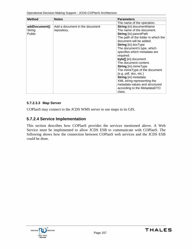
Operational Decision Making Support - JCDS-COPlanS Architecture
Page 157
Method Notes Parameters The name of the operation.
addDocument() String Public
Add a document in the document repository.
String [in] documentName The name of the document. String [in] parentPath The path of the folder in which the document will be added. String [in] docType The document's type, which specifies which metadata are required. byte[] [in] document The document content. String [in] mimeType The mimeType of the document (e.g. pdf, doc, etc.) String [in] metadata XML string representing the metadata values and structured according to the MetadataDTO class.
5.7.2.3.3 Map Server
COPlanS may connect to the JCDS WMS server to use maps in its GIS.
5.7.2.4 Service Implementation This section describes how COPlanS provides the services mentioned above. A Web Service must be implemented to allow JCDS ESB to communicate with COPlanS. The following shows how the connection between COPlanS web services and the JCDS ESB could be done.
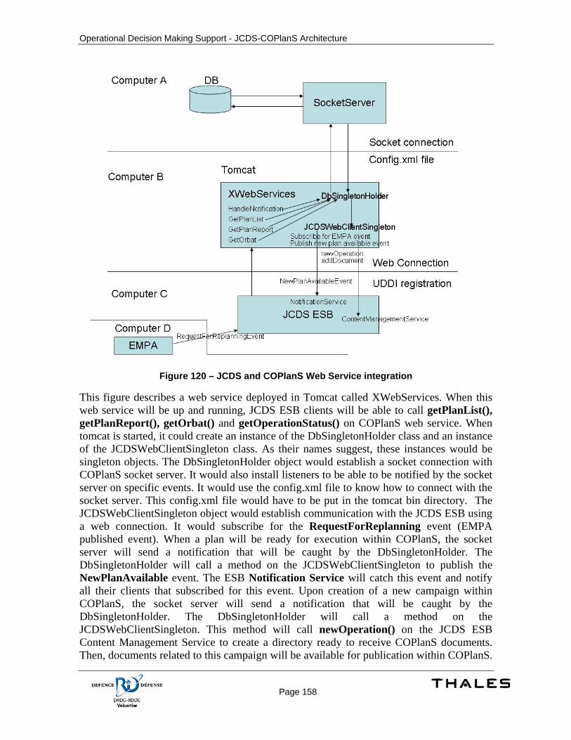
Operational Decision Making Support - JCDS-COPlanS Architecture
Page 158
Figure 120 – JCDS and COPlanS Web Service integration
This figure describes a web service deployed in Tomcat called XWebServices. When this web service will be up and running, JCDS ESB clients will be able to call getPlanList(), getPlanReport(), getOrbat() and getOperationStatus() on COPlanS web service. When tomcat is started, it could create an instance of the DbSingletonHolder class and an instance of the JCDSWebClientSingleton class. As their names suggest, these instances would be singleton objects. The DbSingletonHolder object would establish a socket connection with COPlanS socket server. It would also install listeners to be able to be notified by the socket server on specific events. It would use the config.xml file to know how to connect with the socket server. This config.xml file would have to be put in the tomcat bin directory. The JCDSWebClientSingleton object would establish communication with the JCDS ESB using a web connection. It would subscribe for the RequestForReplanning event (EMPA published event). When a plan will be ready for execution within COPlanS, the socket server will send a notification that will be caught by the DbSingletonHolder. The DbSingletonHolder will call a method on the JCDSWebClientSingleton to publish the NewPlanAvailable event. The ESB Notification Service will catch this event and notify all their clients that subscribed for this event. Upon creation of a new campaign within COPlanS, the socket server will send a notification that will be caught by the DbSingletonHolder. The DbSingletonHolder will call a method on the JCDSWebClientSingleton. This method will call newOperation() on the JCDS ESB Content Management Service to create a directory ready to receive COPlanS documents. Then, documents related to this campaign will be available for publication within COPlanS.

Operational Decision Making Support - JCDS-COPlanS Architecture
Page 159
When a document is approved, it will be available for publication. Upon publication of the document, the socket server will send a notification that will be caught by the DbSingletonHolder. The DbSingletonHolder will call a method on the JCDSWebClientSingleton. This method will call addDocument() on the JCDS ESB Content Management Service to put a copy of this document in the JCDS server disk. The Content Management Service will send a notification to inform all their clients that a new COPlanS document is now available on the JCDS server. Finally when the EMPA system rejects a plan, it will send a RequestForReplanning event on the JCDS Notification Service. Since the JCDSWebClientSingleton object will have subscribed for this event, it will be notified of this event publication. The HandleNotification() service will be called by the JCDS Notification Service. This method will receive the event as argument. Then, a copy of the rejected plan will be created. This copy will not include the rejected plan’s workflow and selected COA. The socket server will receive the creation of the copied plan using a writing transaction on the socket server. A new activity will be added to the list of the assignations of the leader of the copied plan. This activity will be added for the leader of a plan that has no workflow or the leader of a plan that has a workflow which is not started yet.
5.7.2.4.1 Process Specification
When a new operation is created, a corresponding folder structure is created in the document repository. This structure has the plan name as folder root. In the case of two plans created with the same name, their files will be added under the same documents repository structure. If a plan is renamed with an existing plan name, the folder cannot be renamed. The root folder name shall use a unique name (plan identifier).
dcd03e rev.(10-1999)
UNCLASSIFIED SECURITY CLASSIFICATION OF FORM
(Highest Classification of Title, Abstract, Keywords)
DOCUMENT CONTROL DATA
1. ORIGINATOR (name and address) Thales Canada
2. SECURITY CLASSIFICATION (Including special warning terms if applicable) Unclassified
3. TITLE (Its classification should be indicated by the appropriate abbreviation (S, C, R or U) Operational Decision Making Support - JCDS-COPlanS Architecture (U)
4. AUTHORS (Last name, first name, middle initial. If military, show rank, e.g. Doe, Maj. John E.) Maxime Tardif, Gino Pelletier, Guy Gosselin, Dominc Côté, Marco Savard
5. DATE OF PUBLICATION (month and year) March 2009
6a. NO. OF PAGES 159
6b .NO. OF REFERENCES 0
7. DESCRIPTIVE NOTES (the category of the document, e.g. technical report, technical note or memorandum. Give the inclusive dates when a specific reporting period is covered.)
Contract Report
8. SPONSORING ACTIVITY (name and address)
9a. PROJECT OR GRANT NO. (Please specify whether project or grant)
9b. CONTRACT NO. W7701-054996/008/QCL - W7701-8-1681NP
10a. ORIGINATOR’S DOCUMENT NUMBER CR 2009-118
10b. OTHER DOCUMENT NOS
N/A
11. DOCUMENT AVAILABILITY (any limitations on further dissemination of the document, other than those imposed by security classification)
Unlimited distribution Restricted to contractors in approved countries (specify) Restricted to Canadian contractors (with need-to-know) Restricted to Government (with need-to-know) Restricted to Defense departments Others
12. DOCUMENT ANNOUNCEMENT (any limitation to the bibliographic announcement of this document. This will normally correspond to the Document Availability (11). However, where further distribution (beyond the audience specified in 11) is possible, a wider announcement audience may be selected.)
Unlimited
UNCLASSIFIED
SECURITY CLASSIFICATION OF FORM (Highest Classification of Title, Abstract, Keywords)

dcd03e rev.(10-1999)
UNCLASSIFIED SECURITY CLASSIFICATION OF FORM
(Highest Classification of Title, Abstract, Keywords)
13. ABSTRACT (a brief and factual summary of the document. It may also appear elsewhere in the body of the document itself. It is highly desirable that the abstract of classified documents be unclassified. Each paragraph of the abstract shall begin with an indication of the security classification of the information in the paragraph (unless the document itself is unclassified) represented as (S), (C), (R), or (U). It is not necessary to include here abstracts in both official languages unless the text is bilingual).
Defence R&D Canada –Valcartier (DRDC Valcartier) centre initiated a research activity aimed at investigating and developing approaches and concepts to support operational decision-making within the context of the Canadian Forces Operational Planning Process (CFOPP). In an effort to develop a more effective adaptive planning process, this investigation focused on examining new structured approaches to enhance and facilitate courses of action (COA) analysis and selection. In particular, a review of possible approaches for the dynamic link management between CFOPP elements, for the COA evaluation criteria management, in an effects-based environment and for enhanced decision-matrixes, with associated concepts; was completed. A computer-based system called “Collaborative Operations Planning System (COPlanS)” was used as an experimental framework to demonstrate a possible operationalisation of these approaches. COPlanS has been developed at DRDC Valcartier to support the CFOPP. COPlanS is an integrated flexible suite of planning, decision-aid and workflow management tools aimed at supporting a distributed team involved in the planning of military operations. This document details the design of the mock-ups’ implementation, their interfaces and the changes required in the COPlanS components to support the proposed functionalities. Le Centre de Recherche & Développement pour la Défense Canada – Valcartier (CRDD Valcartier) a entrepris une activité de recherche visant le développement d’approches et de concepts pour améliorer l’aide au décideur dans le contexte du Processus de Planification Opérationnelle des Forces canadiennes (PPOFC). Dans le but de déveloper un processus de planification plus efficace et flexible ; cette étude vise à examiner plusieurs nouvelles approches structurées pour faciliter et améliorer l’analyse et la sélection des suites d’action (SAs). En particulier, une revue des approches possibles a été effectuée, sur l’analyse des liens possibles entre les éléments de planification du PPOFC, sur la gestion des critères d’évaluation pour les Sas (qui retirent des effets opérationels) et sur les matrices d’aide à la décision. Le système numérique automatisé appelé “Collaborative Operations Planning System (COPlanS)”, a servi en tant que base expérimentale, afin de démontrer l’opérationnalisation des approches possibles. COPlanS a été mis au point au CRDD Valcartier pour traiter le PPOFC. COPlanS intègre une série flexible de composantes de planification, d’aide à la décision et d’outils de gestion des processus métiers, visant la planification, en collaboration avec des membres d’équipes dispersées d’opérations militaires. Ce document décrit la conception des prototypes et des interfaces utilisateurs, ainsi que les changements requis dans les différentes composantes de COPlanS pour supporter les fonctionnalités proposées.
14. KEYWORDS, DESCRIPTORS or IDENTIFIERS (technically meaningful terms or short phrases that characterize a document and could be helpful in cataloguing the document. They should be selected so that no security classification is required. Identifiers, such as equipment model designation, trade name, military project code name, geographic location may also be included. If possible keywords should be selected from a published thesaurus, e.g. Thesaurus of Engineering and Scientific Terms (TEST) and that thesaurus-identified. If it is not possible to select indexing terms which are Unclassified, the classification of each should be indicated as with the title.)
Architecture COPlanS Decision Support Operational Planning Process JCDS 21
UNCLASSIFIED
SECURITY CLASSIFICATION OF FORM (Highest Classification of Title, Abstract, Keywords)


Canada’s Leader in Defenceand National Security
Science and Technology
Chef de file au Canada en matièrede science et de technologie pourla défense et la sécurité nationale
www.drdc-rddc.gc.ca
Defence R&D Canada R & D pour la défense Canada
![[XLS] · Web viewKayal, Marie NRC2010022288 Mitchell, Candis NRC2010022289 NRC2010022290 NRC2010022291 Grooms, Diana NRC2010022292 Ross, Elisa NRC2010022293 Nallusamy, Sasikumar NRC2010022294](https://img.pdfslide.net/doc/110x75/5b1bfb3c7f8b9a3c258f44e0/xls-web-viewkayal-marie-nrc2010022288-mitchell-candis-nrc2010022289-nrc2010022290.jpg)