Embed Size (px)
DESCRIPTION
Telecomunication System Guide
Citation preview
Chapter 11
Panduan Teknik Edisi Ke-4 2008 Cawangan Kejuruteraan Elektrik Pg 1 of 19
Telecommunication System
1.0 Introduction The extent of work to be executed by JKR begins at the boundary of the project
site i.e. at the first manhole in the client area. From the TM exchange to this first manhole will be under TM scope of work.
In this chapter we shall be concentrating on ‘The design and the installation of the
voice telecommunication services’ for Government buildings. Internet Protocol (IP) based communication system if any shall be covered under the ICT scope of works.
Topic shall be subdivided as follows:
a) Building Requirement b) Design Of Internal Telephone Layout c) Design Of Internal Telephone Cabling d) Subscriber Distribution Frame (SDF) e) Private Automatic Branch Exchange (PABX) f) External Work g) Coordination With TM
There are a few telecommunication utilities in the countries. TM is the largest. Most of the following information are based on their requirement and practice.
2.0 Building Requirement
There are 3 categories classified by TM:
a) Category 1 -More than 5 storey and any building with total floor space exceeding 650m² -TM specified underground cable exceeding 50 pairs
b) Category 2
-Less than 5 storey with total floor space less than 650m² -TM specified underground cable less than 50 pairs
c) Category 3
-Terrace or link houses for residential purpose only, - Bungalow for residential purpose only.
TM require that plans for telephone facilities for all Category 1 buildings must be drawn up by telecommunication engineers or electrical consultant engineers and submitted to TM for approval. Most of the government complexes fall into this category. All or some of the rooms as stated in Table 3 may be required.
Chapter 11
Panduan Teknik Edisi Ke-4 2008 Cawangan Kejuruteraan Elektrik Pg 2 of 19
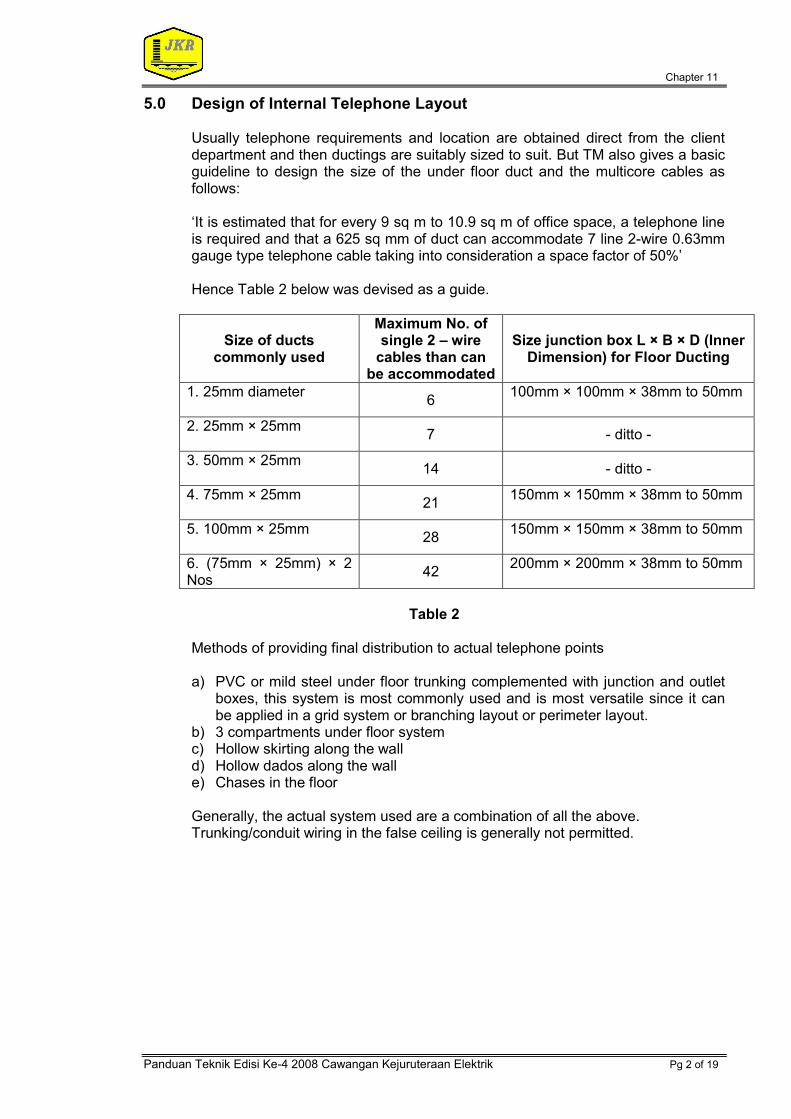
5.0 Design of Internal Telephone Layout Usually telephone requirements and location are obtained direct from the client
department and then ductings are suitably sized to suit. But TM also gives a basic guideline to design the size of the under floor duct and the multicore cables as follows:
‘It is estimated that for every 9 sq m to 10.9 sq m of office space, a telephone line is required and that a 625 sq mm of duct can accommodate 7 line 2-wire 0.63mm gauge type telephone cable taking into consideration a space factor of 50%’
Hence Table 2 below was devised as a guide.
Size of ducts commonly used
Maximum No. of single 2 – wire
cables than can be accommodated
Size junction box L × B × D (Inner Dimension) for Floor Ducting
1. 25mm diameter
6 100mm × 100mm × 38mm to 50mm
2. 25mm × 25mm
7 - ditto -
3. 50mm × 25mm
14 - ditto -
4. 75mm × 25mm
21 150mm × 150mm × 38mm to 50mm
5. 100mm × 25mm
28 150mm × 150mm × 38mm to 50mm
6. (75mm × 25mm) × 2 Nos
42 200mm × 200mm × 38mm to 50mm
Table 2 Methods of providing final distribution to actual telephone points
a) PVC or mild steel under floor trunking complemented with junction and outlet
boxes, this system is most commonly used and is most versatile since it can be applied in a grid system or branching layout or perimeter layout.
b) 3 compartments under floor system c) Hollow skirting along the wall d) Hollow dados along the wall e) Chases in the floor Generally, the actual system used are a combination of all the above. Trunking/conduit wiring in the false ceiling is generally not permitted.

Chapter 11
Panduan Teknik Edisi Ke-4 2008 Cawangan Kejuruteraan Elektrik Pg 3 of 19
6.0 Design of Internal Telephone Cabling
Standard sizes of internal tinned copper conductors, PVC insulated, twin/triple formations and PVC sheathed cables (all coloured grey) are as follows:
1 pr/ 0.63 mm & 10 pr/ 0.5 mm 5 pr/ 0.63 mm 30 pr/ 0.5 mm 10 pr/ 0.63 mm 50 pr/ 0.5 mm 29 pr/ 0.63 mm 100 pr/ 0.5 mm 30 pr/ 0.63 mm 100 pr/ 0.63 mm
For colour codes refer to Appendix 3.
Cabling to DP boxes from SDF are made up of a combination of the above cables. Protective conductors or earth wires shall be run continuously from the top to bottom of the building and connected to SDF. These wires shall be installed nearest to the DP boxes in the riser. It should be noted that all direct lines and other TM facilities at each floor shall be taken from the respective direct line DPs.
7.0 Subscriber Distribution Frame (SDF) The SDF is the final termination point of the TM network and the beginning of the
subscriber network. The SDF consist of: a) Vertical frames or vertical c/w brackets/hooks b) Termination blocks c) Earth bar d) Lightning arrestors TM room (SDF) which will be handed over to TM upon completion of the project normally consists of a minimum three verticals namely:
a) VERTICAL NO. 1 - TM incoming vertical b) VERTICAL NO. 2 - TM outgoing vertical c) VERTICAL NO. 3 - Equipment (PABX) vertical On the distribution side, consumer room (Intermediate Distribution Frame, IDF) can be combined with PABX room and normally consists of a minimum of three vertical namely: a) VERTICAL NO. 1 - From equipment vertical SDF b) VERTICAL NO. 2 - Outgoing to extension DPs c) VERTICAL NO. 3 - Incoming from PABX
For a smaller system where SDF is combined in the same room with IDF equipment vertical can be omitted as shown in Appendix 1
Chapter 11
Panduan Teknik Edisi Ke-4 2008 Cawangan Kejuruteraan Elektrik Pg 4 of 19
8.0 TM Incoming Vertical
TM incoming cables from their exchange shall be terminated at this vertical. Normally a 100 pair vertical is sufficient to cater for the entire telecommunication network of the project. The size of the termination blocks required for the incoming vertical is according to the size of the TM incoming cable which in turn depends on the number of trunk lines to PABX, trunk lines for direct telephones and public phones, data communication (telefax, telex, digital lines, leased lines, etc). Connection between various verticals shall be done via jumpers or jumper cables meant to activate the required lines.
9.0 TM Outgoing Vertical
The TM outgoing vertical shall cater to all direct line DPs. This includes all the trunk lines to the PABX. The size of termination block shall be the total pairs of all the direct lines DPs and the PABX trunk lines. The vertical frame shall be sufficiently sized to house these termination blocks.
10.0 Equipment Vertical
Equipment vertical is required when there is a requirement for PABX. Trunk lines to the PABX can be distributed either from the equipment vertical to distribution vertical or the floor direct lines DP for multi tenants high rise building as shown in Appendix 2 The quantity of the termination blocks shall be the summation of total pairs of trunk line cables designed for maximum capacity of the PABX.
11.0 Distribution Vertical
There are two types of distribution vertical, namely the incoming and outgoing distribution from PABX for extension lines. Connection from PABX shall be terminated to the incoming distribution vertical. The quantity of the termination blocks shall be the summation of extension line cables designed for. The frame shall be large enough to mount these termination blocks.
The tie cables for each floor extension DPs shall be pulled from outgoing distribution vertical. The quantity of the termination blocks shall be the summation of total pairs of extension DPs design for. The frame shall be large enough to mount these termination blocks.
12.0 Earth
TM requires that SDF earth to be less than 5 ohms. However, if the earth of PABX is connected to the SDF earth bar the earth resistance should then be less than 1 ohm.
13.0 Lightning Arrestors
Lightning arrestors shall be installed at the TM incoming vertical for the TM incoming cable and at the Distribution vertical for any other external tie cables (underground or overhead). The size of these lightning arrestors shall be

Chapter 11
Panduan Teknik Edisi Ke-4 2008 Cawangan Kejuruteraan Elektrik Pg 5 of 19
equivalent to the size of the cables. It shall also be of the quick connect gas filled type. Typical descriptions of the SDF may be as follows:
a. Wall mounted SDF c/w 4 no. 200 (4 x 200) pair vertical frames, 550 pairs
quick connect termination block and 3 x 10 pair lightning arrestors. or
b. Wall mounted SDF c/w 6 no. 100 (6 x 100) pair vertical frames, 550 pairs quick connect termination block and 3 x 10 pair lightning arrestors. or
c. Wall mounted SDF c/w 2 no. 100 (2 x 100) pair vertical frames, 550 pairs
quick connect termination block and 3 x 10 pair lightning arrestors. 14.0 Private Automatic Branch Exchange (PABX) 14.1 What Is PABX Equipment?
PABX is a kind of telephony switching equipment. Others of the same category are key phone system, PMBX, Hybrid systems, etc.
14.2 When to Use a PABX?
As a basic but non restrictive guide, a PABX is required when there is a need for more than 40 extensions (this may be the total number of telephone points requested by the client plus 20 % future development)
A key phone system may be more economical for extension less than 40 and with very minimal future expansion. There are also IP base type PABX. The usage and design of such system shall be discussed with ICT design section.
14.3 Sizing of PABX.
a. Sketch all the floor DP boxes schematic diagrams. b. Totaling the sizes of all DP boxes shall give the maximum capacity of your
PABX.
c. The minimum capacity of PABX shall be the present telephone point requirement.
d. Maximum allowable ratio by TM is 1 DEL: 10 extensions. For flexibility the
ratio may range from 1 DEL to 5, 6, 7 or 8 extension. This depends greatly on the traffic flow normally expected by the client.
Note: DEL – Direct Exchange Line or Trunk Lines

Chapter 11
Panduan Teknik Edisi Ke-4 2008 Cawangan Kejuruteraan Elektrik Pg 6 of 19
14.4 Working Example:
Referring to schematic diagram in Appendix 1, we have a 3 storey block with 2 numbers of 30 pair, 1 number of 20 pair and 1 number of 10 pair extensions DPs.
MINIMUM capacity: 22 + 15 + 20 + 5 = 62 + 20% = 62 + 12.4
= 74.4 ext (rounding up) approx. = 75 ext
No. of trunklines (DEL) = 75 / 6
= 12.5 DEL or approx. 13 DEL
MAXIMUM capacity : 30 + 20 + 30 + 10 = 90 ext No. of trunklines = 90 / 6
= 15 DEL
Assuming a heavy traffic flow, the size of the PABX may be as follows, but it is up to the designer to decide on the economical capacity after consultation with the client :- Minimum no. of extension lines - 75 Maximum no. of extension lines - 90 Minimum no. of trunk lines - 13 Maximum no. of trunk lines - 15
14.5 PABX Specification
The following shall be specified as minimum requirements of a PABX: a) Type approved by TM b) Digital c) Stored program control, SPC d) Compatible with ISDN technology (using ISDN interface) e) Port type f) Maintenance free battery (for small system only) g) IDF quick connect termination type h) Earthing shall be less than 1 ohm i) Testing and commissioning j) Training k) Drawing and manuals
14.6 PABX Facilities All PABX have the following type of facilities:
a) minimum or standard facilities b) optional facilities (card have to be specifically purchased and stated in the BQ,
e.g. Direct In Dialing - DID, ISDN, etc) c) programmable facilities (group hunting line, call pick up, follow me, etc)
Chapter 11
Panduan Teknik Edisi Ke-4 2008 Cawangan Kejuruteraan Elektrik Pg 7 of 19
TM however requires that for the following facilities prior application must be submitted for their planning as it involves additional TM telephone lines: a) Tie lines between PABXs b) DID more than 100 extensions (to reduce traffic congestion) c) Data line
15.0 Room Requirement
Only PABX with ultimate capacity of more than 300 extensions require separate rooms by itself, its batteries and its operators. Otherwise separate rooms are not needed, but when space is not a restriction it is preferable to have these rooms separately for smaller systems. The PABX room shall be/have:
a) Free from susceptible vibration, always from direct sunlight and dust. Moisture
must be controlled at 30 – 65% for less than 300 extensions, a normal air conditioned office is sufficient but bigger systems require 24 hrs air conditioning at 15 – 30 degrees Celsius.
b) Floor able to withstand 300 – 1000 kg / sq meter depending on type and
capacity.
c) Flooring of material that is anti static, easy to clean and not susceptible to accumulation of dust, preferably vinyl type.
d) Required 2 no. standard 13A 3 pin socket outlet power point. However, PABX
of capacity exceeding 1000 extensions require higher current rating and three phase supply.
e) Trunking or cable trays must be provided and shall be sufficiently large to
accommodate PABX cables from PABX equipment to SDF room or the riser distribution box and the operators’ room.
f) Separate IDF required for the PABX terminations.
g) CO2 or other suitable type fire fighting preferred. No water sprinkler allowed.
h) Good to equip with wall mounted lockable cabinets to house manuals for the
PABX maintenance and programming. i) PABX shall be placed at least 1 meter from the wall and have a 1 meter
allowance in front for maintenance purposes.
j) For large systems when a separate battery room has to be provided it shall be located adjacent to PABX rooms and ventilated to prevent harmful effects of battery acid and fumes.
k) Smaller batteries of the sealed maintenance free type may be installed in a
separate cubicle in the same PABX room.
l) The separate battery room shall be equipped as follows:
Glazed tiles up to 1.5m around all sides of the wall Exhaust fan Minimum room size 3m x 1.8m Wash basin

Chapter 11
Panduan Teknik Edisi Ke-4 2008 Cawangan Kejuruteraan Elektrik Pg 8 of 19
Exhaust fan
m) When separately provided, the operators room shall be situated not more than 50 meters away from PABX room. It should be sized to comfortably seat the required number of operators. It shall be of half glass partitions furnished with suitable operator tables and chairs and with 1 extension line of category C type.
Table 3 shows the several types of telecommunication room and criteria.
16.0 Acceptance Test and Training TM does not test or commission the PABX. It is the duty of the consultant to check that all facilities as required in the specification are provided and complied to. It is also the duty of the consultant to ensure that appropriate training is conducted by the PABX supplier / contractor for JKR staff and of course the end users. At the end of the training the supplier / contractor shall provide hard copy of programmed extension numbers with circuit and location, programmed telephone facilities demonstrated during the training session.
17.0 External Works
This topic shall be subdivided into two namely: a) Civil Engineering work b) Underground cabling
17.1 Civil Engineering Work
This portion of work involves the construction of manholes, joint boxes, duct laying etc. Generally, the most common manholes/joint boxes constructed for most JKR projects are as follows: a) Telephone pits b) JB30 c) JC9 d) JRC7 e) JC9/C f) R2A
And all or some of them may be requires depending on the extent scope of the project and also on the recommendation and approval of the local TM staff. The detailed plans of all the above may be obtained from the local network offices of TM. TM has standardized the use of 100mm diameter PVC ducts for all the ducting required. Usually, these ducts have to be encased in concrete at road crossings and crossing with other services and when more than 8 ducts are required. TM has also required the use of GI pipes where drains or streams have to be crossed. GI pipes are also required where there is insufficient earth coverage underground. As a rule of thumb 110cm of cover is required above the PVC ducts. The exact maximum distances between joint boxes were not defined by TM but generally it is about 120 meters for plastic fully filled cables. Clearance from other services:
Chapter 11
Panduan Teknik Edisi Ke-4 2008 Cawangan Kejuruteraan Elektrik Pg 9 of 19
Water mains
a) At least (nominal) 150mm running parallel. b) At least 50mm at crossing
Electricity supplies a) High voltage single core cables exceeding 650V at least 460mm with no
exceptions. b) High voltage multicore cables exceeding 650V at least 300mm. c) Low and medium voltage cables not exceeding 650V at least 50mm d) Where the two sets of electrical plants cross each other
17.2 Underground Cabling
For JKR projects we are usually required to use underground cables in PVC ducts. It is recommended by TM that we use Plastic fully filled telephone cables. For this distribution cable, it is important to specify the parameter of capacitance to be 55 nano Farad/km.
18.0 Coordination with TM 18.1 Plan Approval Process
It is an advantage to have a preliminary discussion between consultant and TM before submission of proposed infrastructure plan for telecommunication services. It helps TM to identify the development at an early stage enabling the planning of cable network for the development. The consultant can obtain relevant information on the existing plant so that accurate proposal can be made and method on how to link to this plan can be made. If necessary a site visit is to be arranged so that a better picture can be obtained. Other issues on the provision of SDF room, frame, blocks and the type of material to be used are normally discussed during this preliminary meeting. Once all information have been obtained, the consultant will submit two sets of draft proposal to TM for checking. A copy of the plan is then returned to the consultant for further amendments (if required) before submitting four sets of the final proposal for approval.
18.2 Implementation
It is the responsibility of the developer (in this case JKR) to engage registered contractors with Pusat Khidmat Kontraktor under subhead I-9 and VIII-2a/b to carry out Telecom infrastructure works. Details of the contractor and the work schedule have to submit to TM before the work begins. During the implementation stage, TM supervisors will perform spot checks to ensure that the work is executed as planned. Any change to the plan has to be referred back to TM for further discussion and approval. On the completion of the work, the consultant will have to inform TM for the joint acceptance test.
18.3 Acceptance Testing
Acceptance testing shall be carried out jointly between TM staff, consultant and the contractor on the following works:-

Chapter 11
Panduan Teknik Edisi Ke-4 2008 Cawangan Kejuruteraan Elektrik Pg 10 of 19
18.3.1 External Civil Works a) Rodding of ducts installed by contractor right to the duct seal in the building. b) Checking the manhole dimensions, fittings and finishing. c) Checking the duct seal for water leakage into the building. 18.3.2 Internal trunking
a) Perforated cable tray finishes such as smooth bending, clearance between
trays and ceilings/other services. b) Riser trunking, riser DP boxes, riser rooms plus labeling of the DP boxes. c) Junction boxes and floor trunking, depth of junction boxes, finishing and draw
wires between junction boxes. 18.3.3 Cabling
a) Insulation resistance (IR) test for every cable pair provided between SDF and
the individual riser DP. b) Continuity test for every cable pair from SDF to riser DP. c) Earth resistance measurement of SDF frame shall be less than 1 ohm.
The foregoing notes are only meant as a brief guide to those who are new to a telephone system design. More detailed information and knowledge of the telephone service are definitely required for the complete detail design. However it is hoped that the brief guide and notes may serve as a stepping stone in the initial design.

Chapter 11
Panduan Teknik Edisi Ke-4 2008 Cawangan Kejuruteraan Elektrik Pg 11 of 19
Table 3: Guideline for Telecommunication Requirement and Criteria
NO ROOM TYPE PROPOSED SIZE (mm)
CRITERIA / GUIDE
1.0 Telecom Operator’s Room
PSTN: TM, Time Tel. Maxis, Bina Riang, etc.
1.1 SDF Room (Refer Diagram 1.1)
2000 × 2000 (Up to 50 DEL)
3000 × 3000 (>50 DEL)
for more refer to Table 1.1
Entry ducts from outside the building shall be designed to run parallel with the length of the longer side of the SDF room. Any turning or bending shall be avoided.
SDF room must be flood free either on ground or 1st floor with a 150mm kerb across doorway (basement not allowed).
Must be dust free - avoiding louvered doors and windows. : Normally equipped with Exhaust Fan, A/C if located in the basement / lower ground floor Must be fitted with suitable lighting At least 2 no. of 13A power points. Sprinkler system not allowed.
Must be provided with one lockable cabinet, table and chair for TM staff use.
1.2 MDP Room < 50 DEL MDP room with telephone pit
1.3 Fiber Optic room
Minimum 4000(L) × 4000(W) x 3000(H)
Actual size dependent on
TM local infrastructure
Provided with pit or cable trench Must be flood free either on ground or 1st floor with a 150mm kerb across doorway (basement not allowed).
Must be dust free - avoiding louvered doors and windows. Equipped with Exhaust Fan, 24 hrs A/C
Must be fitted with suitable lighting At least 3 no. of 13A power points. 30A 3 phase DB (TNB main supply) for rectifier Framed Schematic diagram installed on wall

Chapter 11
Panduan Teknik Edisi Ke-4 2008 Cawangan Kejuruteraan Elektrik Pg 12 of 19
NO ROOM TYPE PROPOSED SIZE (mm)
CRITERIA / GUIDE
2 separate earthing both less than 1 ohm Sprinkler system not allowed. Must be provided with one lockable cabinet, table and chair for TM staff use.
2.0 Consumer’s Room Build up area up to 9100 sq.m
2.1 IDF Room (Refer Diagram 2.1)
1500 × 1000 Shall be nearby the SDF Room
2.2 PABX Room (Refer Diagram 2.2)
1500 × 1500 May be combined with IDF Room or located elsewhere on other floor A/C; 3 nos S/S/O
2.3 Telephonist Room
1500 × 2000
Separate room for 1 person only Should not be > 50m away from PABX Room With half glass door or half glass partition Can also be part of admin, office area
2.4 Riser Room
TM’s sizes: <10 storeys : 0.9m x 0.45m, ≥ 10 storeys : 1.2m x 0.45m
JKR practice according to diagram 2.4
The cable risers stretch from the SDF room to the full height of the building and have access to distribution conduits on each floor of the building. For buildings with large floor areas (longer than 90m) in each storey, more than one cable riser at strategic points may be planned on every floor. This riser hole shall be sealed up with fire resistant barriers. It is important that no other services be allowed in this enclosure. Enclosures shall have fire resistant locked doors of min 2.1m height with the words ‘TELECOM RISER’ displayed on it One set of keys of the door shall be kept by owner for safe custody and the other by TM.
2.4.1 IT Riser Room (Refer to Diagram 2.4.1)
2000 × 2000 Best to be A/C or at least naturally ventilated
2.4.2 Telephone Riser / DP Room (Refer to Diagram 2.4.2)
1000 × 900 Should not be the same room as IT, but must be side by side or nearby
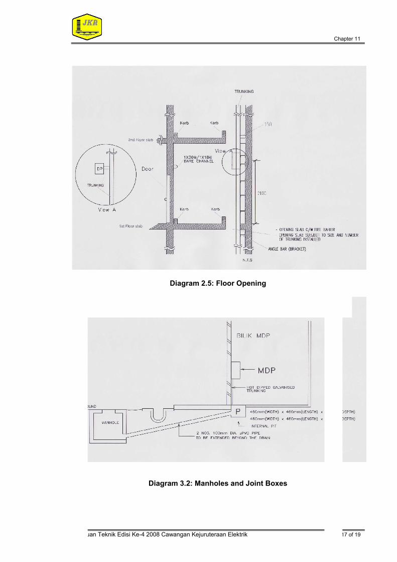
2.5 Floor Opening (Refer to Diagram 2.5)
Subject to size and number of
trunking installed
Will be covered by approved 2 hrs fire barrier, by Elect. Contr. Door to follow UBBL 75mm kerb around the floor opening; 50mm kerb across the door
NO ROOM TYPE PROPOSED SIZE (mm)
CRITERIA / GUIDE

Chapter 11
Panduan Teknik Edisi Ke-4 2008 Cawangan Kejuruteraan Elektrik Pg 13 of 19
NOTE: All sizes given may differ according to the sizes of the project.
3.0 Infrastructure Requirement
3.1
Screeding to cover the Integrated Underfloor Ducting System or Raised Floor System
50
5 – 10
200 - 300
To cover the boxes (a total provision of 55mm) To level the slab (60mm thick or screeding required) Floor slab shall be recessed to allow for raised floor system
3.2 Manholes (external) (Refer to Diagram 3.2)
JC9/C For road, tarmac, hard standings
3.3 Joint Boxes / Telephone Pits (internal) (Refer to Diagram 3.2)
2 sizes: 460(I) × 460(w) × 460(d) or 460(I) × 460(w) × 760(d) Required at all cable access into the building Conduit required from floor junction boxes to wall telephone outlet Several different sizes available Design to follow TM Guidelines of Planning for Bulding
3.4 Trenching Requirement (for SDF Room) (Refer to Diagram 1)
Layout of the trenches may differ according to projects; Elect. Designer will furnish the info.
3.5 Earthing
≤ 1 ohm

Chapter 11
Panduan Teknik Edisi Ke-4 2008 Cawangan Kejuruteraan Elektrik Pg 14 of 19
Diagram 1.1: SDF Room
Size of Cables (Pairs)
For Incoming Cable SDF Room (L × W × H)
(m)
Max. No. of Floor
No. of Entry Duct
Width of Cable Tray
(mm) 50 – 200 2 300 2.4 × 1.8 × 3 6
200 – 400 2 – 4 300 – 350 3 × 2.4 × 3 8 400 – 600 4 350 – 400 3.6 × 3 × 3 10
600 – 1000 6 400 4.8 × 3 × 3 12 > 1000 > 6 > 400 < 6 × 3 × 3 > 12
Table 1.1: Standard room size requirement for SDF rooms.

Chapter 11
Panduan Teknik Edisi Ke-4 2008 Cawangan Kejuruteraan Elektrik Pg 15 of 19
Diagram 2.1: IDF Room
Diagram 2.2: PABX Room

Chapter 11
Panduan Teknik Edisi Ke-4 2008 Cawangan Kejuruteraan Elektrik Pg 16 of 19
Diagram 2.4.1: IT Riser Room
Diagram 2.4.2: Telephone Riser / DP Room
Chapter 11
Panduan Teknik Edisi Ke-4 2008 Cawangan Kejuruteraan Elektrik Pg 17 of 19
Diagram 2.5: Floor Opening
Diagram 3.2: Manholes and Joint Boxes

Chapter 11
Panduan Teknik Edisi Ke-4 2008 Cawangan Kejuruteraan Elektrik Pg 18 of 19
Appendix 1

Chapter 11
Panduan Teknik Edisi Ke-4 2008 Cawangan Kejuruteraan Elektrik Pg 19 of 19
Appendix 3
Pair No. Colour or Conductor Insulation
A leg (1st wire) B leg (2nd wire) 1 2 3 4 5 6 7 8 9 10
White “ “ “ “
Red “ “ “ “
Blue Orange Green First 5 Brown pair unit Grey Blue Orange Second Green 5 pair Brown unit Grey
10 pair unit
1 pair only White Orange 3 wire White Orange
Colour Code for Internal PVC Telephone Cable with Unit Type Configuration.
Unit No. (10 pair unit) Colour of Binder 1 2 3 4 5 6 7 8 9
10
Blue Orange Green Brown Grey
Blue – White Orange – White Green – White Brown – White Grey – White
Colour of Binder Tapes