Embed Size (px)
Citation preview
TB 700-2NAVSEAINST 8020.8BTO 11A-1-47DLAR 8220.1
Joint Technical Bulletin
DEPARTMENTOF DEFENSEAMMUNITIONANDEXPLOSIVESHAZARDCLASSIFICATIONPROCEDURES
HeadquarterDepartment of the Army, the Navy,the Air Force,and the Defense Logistics AgencyWashington, D. C.
5 January 1998Unclassified
TB 700-2/NAVSEAINST 8020.8B/TO 11A-1-47/DLAR 8220.1DEPARTMENT OF DEFENSE AMMUNITION AND EXPLOSIVES HAZARD CLASSIFICATIONPROCEDURES
T h i s r e v i s i o n - -
Adds UN Test Series 1 through 7 protocol wi th f low chart . Selects U.S. testsf rom pro toco l . S ta tes po l i cy to accep t a l te rna te UN tes ts (para 5 -1 ) .
Prov ides more spec i f i c tes t requ i rements and pass / fa i l c r i te r ia o rgan ized byt e s t , w i t h d i a g r a m s ( p a r a s 5 - 2 t h r u 5 - 9 ) .
A d d s f l a s h p o i n t t e s t f o r l i q u i d e x p l o s i v e s ( p a r a 5 - 9 ) .
Rev ises b las t measurements p rocedures and in te rp re ta t ions (para 6 -2 ) .
Revises f ragment hazard assessment procedures (para 6-3).
Incoporates the UN thermal hazards assessment procedures and cr i ter ia (para6 - 4 ) .
Replaces Sample Summary Sheet and NATO Data Card (for ammunition) with sampleDD forms (para 6-5c and f igs 6-7 and 6-8) .
I d e n t i f i e s a l t e r n a t e h a z a r d c l a s s i f i c a t i o n t e s t ( w i t h r e s t r i c t i o n s ) t h a th a v e a p p l i c a t i o n f o r q u a l i f i c a t i o n , i n s e n s i t i v e m u n i t i o n s , a n d s y s t e mv u l n e r a b i l i t y ( p a r a 6 - 6 ) .
Prov ides new Serv ice and DOE addresses fo r in te r im hazard c lass i f i ca t ionr e s p o n s i b i l i t i e s a n d a c t i o n s ( p a r a 7 - 2 ) .
Adds DOT/UN Test Series 3 requirements. S t a t e s p o l i c y t h a t 7 0 - c a r d g a p t e s t( o r A R D E C s o l i d g u n p r o p e l l a n t s h o c k s e n s i t i v i t y t e s t ) a n d c a p t e s t a r er e q u i r e d f o r i n t e r i m H D 1 . 3 c l a s s i f i c a t i o n ( p a r a 7 - 3 a ) .
G i v e s p r o c e d u r e s f o r o b t a i n i n g i n t e r n a t i o n a l s h i p m e n t o f i t e r i m h a z a r dc lass i f ied i tems w i th competen t au thor i t y approva l (para 7 -3d) .
R e v i s e s r e s p o n s i b i l i t i e s a n d p r o c e d u r e s f o r m a n a g i n g t h e J o i n t H a z a r dClass i f i ca t ion Sys tem (JHCS) (para 8 -3 ) .
References the changes in DOT hazard c lassi f icat ion procedures (para 8-4).
Redef ines JHCS data input and format (para 8-5).
HeadquartersDepartment of the Army, the Navy,the Air Force,and the Defense Logistics AgencyWashington, DC5 January 1998
* T B 7 0 0 - 2N A V S E A I N S T 8 0 2 0 . 8 BT O 1 1 A - 1 - 4 7D L A R 8 2 2 0 . 1
Joint Technical Bulletin
DEPARTMENT OF DEFENSE AMMUNITION AND EXPLOSIVES HAZARD CLASSIFICATIONP R O C E D U R E S
By order of the Secretary of the Army: By order of the Secretary of the Navy: By Order of the Secretary of the Army:
DENNIS J. REIMER GEORGE R. STERNER RONALD R. FOGLEMANGeneral, United States Army Vice Admiral, United States Navy General, United States Air ForceChief of Staff Commander, Naval Sea Systems Commander Chief of Staff
Official: Official:
HENRY VICCELLIO, JR.JOEL B. HUDSON General, United States Air ForceAdministrative Assistant to the Commander, AFMC
Secretary of the Army By Order of the Director, Defense LogisticAgency:
RAUL A. MARTINEZDASC Administrator
History. This is a complete revision of TB700-2. NAVSEAINST 8020.8A, TO11A-1-47, and DLAR 8220.1.Summary. This publication sets forth de-tailed procedures for hazard classifying am-munition and explosives in accordance withDepartment of Transportation regulations,North Atlantic Treaty Organization guide-lines, and United Nations recommendations.Applicability. This TB applies to the De-fense Logistics Agency, the Navy, the AirForce, the Active Army, the Army NationalGuard, the U.S. Army Reserve.
Proponent and exception authority. Alexandria, VA 22331-0600, Phone: DSNThe proponent of this TB is the Chairman, 221-8624, Commercial: (703) 325-8624;Department Of Defense Explosives Safety FAX (703) 325-6227.Board, Room MC. Hoffman Building 1,2461 Eisenhower Avenue, Alexandria, VA22331-0600, Phone: DSN 221-8624. Com-
Distribution. To be distributed in accord-
mercial: (703) 325-8624; Fax: (703)ance with initial distribution number (IDN)
325-6227.343699 requirements for TB 700-2.
Suggested Improvements. Users are in-vited to send comments, corrections, and sug-gested improvements directly to theChairman, Department Of Defense Explo-sives Safety Board, Room 856C. HoffmanBuilding 1, 2461 Eisenhower Avenue,
Contents (Listed by paragraph and page number)
Chapter 1Introduction, page 1Purpose • 1-1, page 1NATO Standardization Agreement (STANAG) • 1-2, page 1use of the procedures • 1-3, page 1Application • 1-4, page 1Hazards not determined by these criteria • 1-5, page 1Predominant hazard • 1-6, page 1Samples for laboratory examination • 1-7, page 1Non-Class 1 and non-regulated articles • 1-8, page 1Transportation of unexploded ordnance (UXO) • 1-9, page 1
AMMUNITION, INCENDIARY • 2-4, page 2AMMUNITION, PRACTICE • 2-5, page 2AMMUNITION, PROOF • 2-6, page 2AMMUNITION, SMOKE • 2-7, page 2AMMUNITION, TEAR-PRODUCING, with bunter, expelling
charge or propelling charge • 2-8, page 2AMMUNITION, TOXIC! with bunter, expelling charge or
propelling charge • 2-9, page 2ARTICLE, EXPLOSIVES • 2-10, page 2ARTICLES, EXPLOSIVES, EXTREMELY INSENSITIVE
(ARTICLES, EEI) • 2-11, page 2ARTICLES, PYROPHORIC • 2-12, page 2ARTICLES, PYROTECHNIC, for technical purposes • 2-13,
page 2Chapter 2 BLACK POWDER (GUNPOWDER) • 2-14. page 2Glossary, page 2 BOMBS • 2-15, page 2AMMONIUM-NITRATE-fuel oil mixture (ANFO) • 2-1, page 2 BOOSTERS • 2-16, page 2AMMUNITION • 2-2, page 2 BURNING REACTION • 2-17, page 2AMMUNITION, ILLUMINATING. with or without burster, BURSTERS, EXPLOSIVE • 2-16, page 2
expelling charge or propelling charge • 2-3, page 2 CARTRIDGES, BLANK • 2-19, page 3
This publication supersedes TB 700-2, NAVSEAINST 8020.B, AF TO 11A-1-47, DLAR 8220-1, 5 December 1989.TB 700-2/NAVSEAINST 8020.8B/TO 11A-1-47/DLAR 8220.1 • 5 January 1998 i
Unclassified
Contents-Continued
CARTRIDGES, FLASH • 2-20, page 3CARTRIDGES FOR WEAPONS • 2-21, page 3CARTRIDGES FOR WEAPONS, INERT PROJECTILE • 2-22.
Page 3CARTRIDGES, POWER DEVICE • 2-23, page 3CARTRIDGES. SIGNAL • 2-24, page 3CARTRIDGES, SMALL ARMS • 2-25, page 3CASE-S, CARTRIDGE, EMPTY, WITH PRIMER • 2-26, page 3CASES. COMBUSTIBLE. EMPTY, WITHOUT PRIMER • 2-27,
page 3CHARGES, BURSTING • 2-28, page 3CHARGES, DEMOLITION • 2-29, page 3CHARGES, DEPTH • 2-30, page 3CHARGES. EXPELLING • 2-31, page 3CHARGES, EXPLOSIVE, COMMERCIAL, without detonator
• 2-32, page 3CHARGES. PROPELLING • 2-33, page 3CHARGES, PROPELLING FOR CANNON • 2-34, page 3CHARGES, SHAPED, COMMERCIAL. without detonator • 2-35.
page 3CHARGES. SHAPED, FLEXIBLE. LINEAR • 2-36, page 3CHARGES, SUPPLEMENTARY. EXPLOSIVE • 2-37, page 3COMPATIBILITY • 2-38, page 3COMPONENTS, EXPLOSIVE TRAIN, N.O.S. • 2-39, page 3COMPOSITE PROPELLANT • 2-40, page 3CONTRIVANCES, WATER-ACTIVATED, with burster, expelling
charge or propelling charge • 2-41, page 3CORD, DETONATING, flexible • 2-42, page 3CORD (FUSE) DETONATING, metal clad • 2-43, page 3CORD, IGNITER • 2-44, page 4CUTTER, CABLE, EXPLOSIVE • 2-45, page 4DEBRIS • 2-46, page 4DEFLAGRATION REACTION • 2-47, page 4DETONATION REACTION • 2-48, page 4DETONATOR ASSEMBLIES, NON-ELECTRIC, for blasting
• 2-49, page 4DETONATORS • 2-50, page 4DoD COMPONENT (DODC) • 2-51, page 4DYNAMITE • 2-52, page 4EFFECTIVE EXPLOSIVE WEIGHT (EEW) • 2-53, page 4ENTIRE LOAD AND TOTAL CONTENTS • 2-54, page 4EX NUMBER • 2-55, page 4EXPLODE • 2-56, page 4EXPLOSION REACTION • 2-57, page 4EXPLOSION OF THE TOTAL CONTENTS • 2-58, page 4EXPLOSIVE, BLASTING • 2-59, page 4EXPLOSIVE, BLASTING, TYPE A • 2-60, page 4EXPLOSIVE, BLASTING. TYPE B • 2-61, page 4EXPLOSIVE, BLASTING, TYPE C • 2-62, page 4EXPLOSIVE, BLASTING, TYPE D • 2-63, page 4EXPLOSIVE, BLASTING, TYPE E • 2-64, page 5EXPLOSIVE, DEFLAGRATING • 2-455, page 5EXPLOSIVE, DETONATING • 2-66, page 5EXPLOSIVE, EXTREMELY INSENSITIVE DETONATING
SUBSTANCE (EIDS) • 2-67, page 5EXPLOSIVE PRIMARY • 2-68, page 5EXPLOSIVE, SECONDARY • 2-69, page 5FIREBRAND • 2-70, page 5FIREWORKS • 2-71, page 5FLARES • 2-72, page 5FLASH POWDER • 2-73, page 5FORBIDDEN EXPLOSIVE • 2-74, page 5FRAGMENT • 2-75, page 5FUSE/FUZE • 2-76, page 5FUSE, IGNITER. tubular, metal clad • 2-77, page 5FUSE INSTANTANEOUS, NON-DETONATING
(QUICKMATCH) • 2-78, page 5FUSE, SAFETY • 2-79, page 5
FUZES • 2-80, page 5GRENADES, hand or rifle • 2-81, page 5HAND-HELD SAFE • 2-82, page 5HAZARDOUS FRAGMENT • 2-83, page 5HAZARDOUS FRAGMENT DENSITY • 2-84, page 5HIGH EXPLOSIVE WEIGHT • 2-85, page 5IGNITERS • 2-86, page 5IGNITION, means of • 2-87, page 5INITIATION, means of • 2-88, page 6LIGHTERS, FUSE • 2-89,. page 6MASS EXPLOSION • 2-90, page 6MINES • 2-91, page 6NET EXPLOSIVE WEIGHT (NEW) • 2-92, page 6NET EXPLOSIVE WEIGHT FOR Q-D (NEWQD) • 2-93.
page 6NET PROPELLANT WEIGHT (NPW) • 2-94, page 6NON-REGULATED ARTICLES • 2-95. page 6POWDER CAKE (POWDER PASTE) WETTED • 2-96, page 6POWDER. SMOKELESS • 2-97, page 6PRIMERS, CAP TYPE • 2-98, page 6PRIMERS, TUBULAR • 2-99, page 6PROJECTILES • 2-100, page 6PROPELLANTS • 2-101, page 6PROPULSION • 2-102, page 6QUANTITY DISTANCE (Q-D) • 2-103, page 6RELEASE DEVICES, EXPLOSIVE • 2-104, page 6ROCKET MOTORS • 2-105, page 6ROCKETS • 2-106, page 6SIGNALS • 2-107, page 6SOUNDING DEVICES, EXPLOSIVE • 2-108, page 6STERADIAN • 2-109, page 6SUBSTANCE, EXPLOSIVE • 2-110, page 7SUBSTANCE, PYROTECHNIC • 2-111, page 7SUBSTANCES, EXPLOSIVE, VERY INSENSITIVE
(SUBSTANCES, EVI) N.O.S. • 2-112, page 7TORPEDOES • 2-113, page 7TRACERS FOR AMMUNITION • 2-114, page 7UNEXPLODED ORDNANCE (UXO) • 2-115, page 7WARHEADS • 2-116, page 7WITH MEANS OF INITIATION • 2-117, page 7WITHOUT MEANS OF INlTIATION • 2-118, page 7
Chapter 3Administrative Procedures, page 7Introduction • 3-1, page 7Procedures • 3-2, page 7Notification of classifications • 3-3, page 9
Chapter 4Hazard CIassification, page 11Scope • 4-1, page 11DOT hazard classes • 4-2, page 11Hazard Class 1 assignment procedures • 4-3, page 11Hazard Classes 2 through 9 assignment procedures • 4-4, page 11Non-Class 1 and non-regulated • 4-5, page 11Compatibility group assignment procedure • 4-6, page 11Compatibility groups • 4-7, page 11Assignment of DOT identification number (United Nations
number) • 4-8, page 12Explosive weights for Class 1 items • 4-9, page 12Storage without interim hazard classification • 4-10, page 12
Chapter 5Tests, page 12Hazard classification test protocol • 5-1, page 12UN Test Series 1 (optional) • 5-2, page 13UN Test Series 2 (optional) • 5-3, page 15Test Series 3 (mandatory) • 5-4, page 15UN Test Series 4 (mandatory where appropriate) • 5-5, page 17
ii TB 700-2/NAVSEAINST 8020.8B/TO 11A-1-47/DLAR 8220-1 • 5 January 1998
Contents-Continued
UN Test Series 5 (mandatory for Hazard Division 1.5) • 5-6,page 18
UN Test Series 6 (mandatory for Hazard Divisions 1.1, 1.2, 1.3and 1.4) • 5-7, page 19
UN Test Series 7 (mandatory for Hazard Division 1.6) • 5-8,page 21
Additional test • 5-9, page 24
Chapter 6Instrumentation, Interpretation of results and alternate
tests, page 62Introduction • 6-1, page 62Blast measurement8 • 62, page 62Fragment hazard assessment • 6-3, page 63Thermal effects assessment • 6-4, page 64Interpretation of results • 6-5, page 64Alternate tests • 6-6, page 66
Chapter 7Interim hazard classification, page 81General • 7-1, page 81Authority • 7-2, page 81Limitations • 7-3, page 82Documentation • 7-4, page 82
Chapter 8Joint hazard classification system, page 83Introduction • 8-1, page 83Background • 8-2, page 83Responsibilities and procedures • 8-3, page 83Department of Transportation (DOT) changes • 8-4, page 83Completion of control record for JHCS revision • 8-5, page 84
Table List
Table 3-1: Methods for establishing final hazard classification,page 8
Table 4-1: DOT hazard classes designator, page 11Table 4-2: DOT hazard class 1 divisions, page 11Table 4-3: DOT Hazard class 2 thru 9 division, page 11Table 6-2: Fragment data requirements, page 64Table 6-1: Hemispherical TNT surface burst-peak pressure and
positive impulse, page 68Table 8-1: Joint Hazard Classification System control record,
page 83Table 8-2: JHCS control record data elements, page 85Table 8-3: Department of Transportation (DOT) label codes,
page 88Table 8-4: Hazard symbol codes, page 88Table 8-5: Department of Transportation (DOT) class codes,
page 88Table 8-6: Department of Transportation (DOT) shipping
description codes, page 89
Figure List
Figure. 3-1: Method for establishing final hazard classification.,page 10
Figure 5-1: UN hazard classification procedures for articles andsubstances, page 25
Figure 5-1A: UN hazard classification procedures for articles. andsubstances (cont.), page 26
Figure 5-2: Cap test configuration for solid -UN Test 1(a) (iii),page 27
Figure 5-3: Gap test configuration for liquid substances--UN Test1(a) (iii), page 28
Figure 5-4: Number eight (USA) detonator, page 29
Figure 5-5: Internal ignition test-UN Tests 1(b) (ii) and 2(b) (ii),page 30
Figure 5-6: Slow cookoff bomb test device- Test 1(b) (iii)and 2(b) (iv), page 31
Figure 5-7: Gap test configuration for solid substances-UN Test2(a) (iii), page 32
Figure 5-8: Cap test configuration for liquid substances-UN Test2(a) (iii), page 33
Figure 5-9: Bureau of explosives impact machino-UN Test 3(a)(i), page 34
Figure 5-10: Bureau of explosives impact machine sampleassembly for solid substances--UN Test 3(a) (i), page 35
Figure 5-11: Bureau of explosives impact machine sampleassembly for liquid substances--UN Test 3(a) (i), page 36
Figure 5-12: ABL friction test configuration-UN Test 3(b) (iii),page 37
Figure 5-13: Termal stability test configuration-UN Test 3(c),page 38
Figure 5-14: Small-scale burning test configuration--UN Test 3(d) (i), page 39
Figure 5-15: Termal stability test for article-UN Test 4(a),page 40
Figure 5-16: Steel tube drop test for liquids-UN Test 4(b) (i).page 41
Figure 5-17: Twelve meter drop test configuration -UN Test 4(b)(ii), page 42
Figure 5-18: Cap sensitivity test configuration-UN Tests 5(a) and7(a), page 43
Figure 5-19: Alternate cap sensitivity test configuration-UN TestsS(a) and 7(a), page 44
Figure 5-20: Deflagration to detonation test configuration-UNTest 4(b) (ii), page 45
Figure 5-21: Typical wood fuel arrangement for external fire testfor Hazard Division 1.5-UN Test 5(c), page 46
Figure 5-22: Prince incendiary spark test arrangement-UN Test5(d), page 47
Figure 5-23: Single package test arrangement -UN Test 6(a),page 48
Figure 5-24: Typical stack test arrangement--UN Test 6(b),page 49
Figure 5-25: Typical wood fuel arrangement for external fire(bonfire) test-UN Test 6(c), page 50
Figure 5-26: RIDS gap test configuration-UN Test 7(b), page 51Figure 5-27: Susan impact test arrangement-UN Test 7(c) (i),
page 52Figure 5-28: Susan projectile-UN Test 7(c) (i). page 53Figure 5-29: Friability test configuration-UN Teats 7(c) (ii) and
7(d) (ii), page 54Figure 5-30: Steel plate and recovery box setup for friability test----
UN Tests 7(c) (ii) and 7(d) (ii), page 55Figure 5-31: Closed vessel for friability test-UN Tests 7(c) (ii) and
7(d) (ii), page 56Figure 5-32: Steel pipe used for RIDS bullet impact, RIDS
external fire test and BIDS slow cookoff test-UN Tests 7(d) (i).7(e), and 7(f), page 57
Figure 5-33: RIDS bullet impact test arrangement-UN Test 7(d)(i), page 58
Figure 5-34: RIDS slow cookoff test--UN Test 7(f) and 1.6 articleslow cookoff test -UN Test 7(h), page 59
Figure 5-35: 1.6 multiple bullet impact test arrangement-UN Test7(i),page 60
Figure 5-36: Tag closed vessel, page 61Figure 61: Idea overpressure vs. time history, page 69Figure 62: Hemispherical TNT surface burst-peak pressure and
positive impulse, page 70Figure 6-3: Velocity/density arena configuration-method 1.
page 71Figure. 6-4: Fragmentation characterization arena-method 1,
page 72
TB 700-2/NAVSEAINST 8020.8B/TO 11A-1-47/DLAR 8220.1 • 5 January 1998 iii

Contents-Continued
Figure 6-5: Fragment collection coordinate system--method 1,page 73
Figure 6-6: Fragment recovery areas for tests 6(b) and 6(c)-method 2, page 74
Figure 6-1: Sample substance data base recording form, page 75Figure 6-7A: Sample substance data base recording form (coat.).
page 76Figure 6-8: Sample ammunition data base recording form, page 77Figure 6-8A: Sample ammunition data base recording form (cont.),
page 78Figure 6-9: Solid rocket motor card gap test protocol, page 79Figure 6-10: Super large-scale gap test configuration, page 80
iv TB 700-2/NAVSEAINST 8020.8B/TO 11A-1-47/DLAR 8220.1 • 5 January 1998
Chapter 1Introduction
1-1. PurposeThis publication sets forth procedures for determining the reactionof ammunition and explosives (as defined in DoD 6055.9-Standard(STD) (see App A, Ref 1) to specified initiating influences fromtests. Based on reactions obtained, it further provides for assignmentof appropriate hazard classifications for transportation and storageas specified in Chapter 4. It seeks to assure that under identicalconditions, all DOD Components (DODCs) will use identical hazardclassifications for ammunition and explosives items.
1-2. NATO Standardization Agreement (STANAG)In the interest of safety and uniformity of hazard classification ofammunition and explosives, NATO STANAG No. 4123 (see AppA, Ref 2) has been developed. The title of this STANAG is“Methods to Determine and Classify the Hazards of Ammunitionand Explosives.” The United States has ratified this STANAG andis implementing it in this document. Those portions of this docu-ment which are indicated as being required by the STANAG mustbe followed until changed or deleted by formal notification actionby the United States to NATO authorities.
1-3. Use of the proceduresa. Procedures herein will be included in any test plan that is
developed by the responsible DODC for a specific new item to betested. They are to be considered as a minimum with regard to thetype and number of tests. Additional tests, both in number and type,may be conducted as desired by the responsible DODC or as re-quired to achieve mutual agreement among DODCs.
b. In order to best utilize limited resources and avoid test redun-dancy, hazard classification test plans should be tailored, to themaximum extent possible within the guidelines contained in thispublication, so that tests for hazard classification, qualification, in-sensitive munitions, and system vulnerability can be organized intoone coordinated test program with the minimum number of requiredassets and tests.
1-4. ApplicationThis publication applies to ammunition and explosives in the condi-tion and form that they are stored and offered for transportation.Usually, this means the packaged item. It will apply for the determi-nation of hazard classifications that arise either from a modificationto existing ammunition or its packaging or from the introduction ofnew ammunition or packaging. It is not intended that this publica-tion will necessarily apply retroactively. However, the responsibleDOW will indicate upon request whether or not the classificationof a particular item has been determined according to this publica-tion. Where it has not and there are doubts as to the validity of theclassification, the responsible DODC will verify its original classifi-cation by means prescribed in this publication. Hazard classifica-tions of record for which documentation of test results is notavailable, and when there is no reason to doubt the validity of theclassification, may be submitted for approval according to paragraph3-2.
1-5. Hazards not determined by there criteriaDuring the development of these procedures, all types of hazardswere considered; however, tests are not included to specificallydetermine the following:
a. Hazards-(1) During various stages of manufacture and assembly.(2) From flight range of guided missiles or rockets.
(3) Associated with launching of a vehicle or tactical missile.(4) Or associated with any other operations that are not transpor-
tation and storage.b. Susceptibility to accidental initiation by-(1) Electrostatic and electromagnetic influence.(2) Rough handling and vibration.(3) Effects of exposure to hot and cold environments.
(4) Mechanical defects.(5) Solar radiation.(6) Temperature shock.(7) Abnormal functioning.(8) Or combat exposure.
1-6. Predominant hazardln the event the ammunition item to be classified contains a hazard-ous material such as: fuel, oxidizer or compressed gas which pres-ents a greater hazard in transportation than the Class 1 material, thenthe protocol for the predominant hazard should be used rather thanthat for Class 1 materials. For instance, if a rocket contains gallonsof flammable liquid and a small igniter, then the proper hazardclassification may be Class 3, rather than Class 1. See Note inparagraph 3-1a.
1-7. Sampler for laboratory examinationTransportation of explosives samples authorized in accordance withparagraph 173.56(d), of 49 CFR (see App A, Ref 3) which have notbeen subjected to tests required for interim hazard classification(para 7-3) are limited to 2.3 kg (5.0 lb) per shipment. The samplesare shipped as Hazard Division 1.1 with an appropriate compatibil-ity group specified.
1-8. Non-Class 1 and non-regulated articlesa. Class 1 comprises explosive articles, except devices considered
to be “hand-held safe” (see chap 2) which contain explosive sub-stances in such quantity or of such a character that their inadvertentor accidental ignition or initiation during transport shall not causeany effect external to the device either by projection, fire, smoke,heat or loud noise (taken from para 1.11. Chapter 1, of App A, Ref4). Hand-held safe articles are identified as non-Class 1.
b. Non-Class 1 articles that do not contain any other classes ofdangerous goods (Classes 2 through 9) as defined in 49 CFR Part173, Subpart D (see App A, Ref 3) are identified as non-regulated.Non-Class 1 articles that do contain other classes of dangerousgoods may be identified as non-regulated based on further evalua-tion (see App A, Ref 3).
1-9. Transportation of unexploded ordnance (UXO)a. Ammunition and explosives are often discovered on current
DOD installations. formerly used defense sites (FUDS) and otherareas affected by DoD activities. DoD UXO found in such circum-stances may be unknown or in a state of deterioration that identifi-cation by markings, nomenclature or other characteristics may beimpossible. Even when identification is made, the original hazardclassification no longer applies. There is a critical need in manycases to transport UXO over public transportation routes. Wherepossible, transport UXO by military vehicle using militarypersonnel.
b. The following procedure is required:(1) UXO must be examined by personnel qualified for Explosive
Ordnance Disposal (EOD) before transporting it from the installa-tion or FUDS. The EOD unit will attempt to identify the ordnanceand affirm in writing that the material is safe for transport.
(2) All unidentified UXO shall be handled, transported and storedas Hazard Division 1.1 and appropriate compatibility group. UXOwill be stored as unserviceable ammunition (DOD 6055.9- STD (seeApp A. Ref 1)).
(3) The cognizant DODC, with local EOD assistance, will deter-mine the appropriate packaging, blocking and bracing, marking andlabeling, and any special handling requirements for transportingUXO over public transportation routes. These procedures will in-clude the amount of material to be shipped Per vehicle and theassigned compatibility group. Documentation to this effect will ac-company each shipment. DD Form 836 is also to accompany eachshipment.
(4) When EOD personnel are not available throughout a clean-upoperation, the delegation of authority by the DODC, or the assignedEOD unit, shall be documented.
TB 700-2/NAVSEAlNST 8020.8B/TO 11A-1-47/DLAR 8220.1 • 5 January 1998 1
(5) If the UXO must be transported by contract vehicle, in addi-tion to the procedures above, the EOD personnel must affirm inwriting that the UXO is not a forbidden explosive under paragraph173.54 of 49 CFR (see App, Ref 3) A, based on standardized EoDevaluation procedures.
(6) Transportation of UXO described in paragraph 1-9 will beaccompanied by EPA Form 8700-22 (8700-22A when necessary)prepared in accordance with 40 CFR paragraph 262.20 (App A, Ref5). Also, see 49 CFR, paragraph 172.205 (App A, Ref 3).
mission of EOD units, nor to the handling of nuclear, biological or(7) These requiremen ts do not pertain to the emergency response
toxic chemical agents. These must be considered on a case-by-basis.
Chapter 2Glossary
2-1. AMMONIUM-NlTRATE-fuel oil mixture (ANFO)A blasting explosive containing no essential ingredients other thanprilled ammonium nitrate and fuel oil.
2-2. AMMUNITIONGeneric term related mainly to articles of military application con-sisting of all kinds of bombs. grenades, rockets, mines. projectilesand other similar devices or contrivances.
2-3. AMMUNITION, ILLUMINATING, with or withoutburster, expelling charge or propelling chargeAmmunition designed to produce a single source of intense light forlighting up an area. The term includes illuminating cartridges, gre-nades and projectiles; and illuminating and target identificationbombs. The term excludes the following articles which are listedseparately: CARTRIDGES; SIGNAL; SIGNAL DEVICES; HANDSIGNALS; DISTRESS FLARES; AERIAL AND FLARES;SURFACE.
2-4. AMMUNITION, INCENDIARYAmmunition containing incendiary substance which may be a solid,liquid or gel including white phosphorus. Except when the composi-tion is an explosive per se, it also contains one or more of thefollowing: a propelling charge with primer and igniter charge; a fuzewith burster or expelling charge. The term includes--
a. AMMUNITION, INCENDIARY, liquid or gel, with burster,expelling charge or propelling charge.
b. AMMUNITION, INCENDIARY, with or without burster, ex-pelling charge or propelling charge.
c. AMMUNITION, INCENDIARY, WHITE PHOSPHORUS,with burster, expelling charge or propelling charge.
2-5. AMMUNITION, PRACTICEAmmunition without a main bursting charge, containing a burster orexpelling charge. Normally it also contains a fuze and a propellingcharge. The term excludes the following article which is listedseparately: GRENADES, PRACTICE.
2-6. AMMUNITION, PROOFAmmunition containing pyrotechnic substances, used to test theperfomance or strength of new ammunition, weapon component orassemblies.
2-7. AMMUNITION, SMOKEAmmunition containing smoke-producing substance such as chloro-sulphonic acid mixture (CSAM), titanium tetrachloride (FM), whitephosphorus or smoke-producing pyrotechnic composition based onhexachloroethane (HC) or red phosphorus. Except when the sub-stance is an explosive per se, the ammunition also contains one ormore of the following: a propelling charge with primer and ignitercharge, or a fuze with burster or expelling charge. The termincludes-
a. AMMUNlTION, SMOKE, with or without burster, expellingcharge or propelling charge.
b. AMMUNITION, SMOKE, WHITE PHOSPHORUS, withburster, expelling charge or propelling charge.
2-8. AMMUNITION, TEAR-PRODUCING, with burster,expelling charge or propelling chargeAmmunition containing tear-producing substance. It also containsone or more of the following: a pyrotechnic substance; a propeIlingcharge with primer and igniter charge; a fuze with burster or expel-ling charge.
2-9. AMMUNITION, TOXIC with burster, expelling chargeor propelling chargeAmmunition containing toxic agent. It also contains one or more ofthe following: a pyrotechnic substance; a propelling charge withprimer and igniter charge; a fuze with burster or expelling charge.
2-10. ARTICLE, EXPLOSIVEAn article containing one or more explosive substances.
2-11. ARTICLES, EXPLOSIVE, EXTREMELY INSENSlTlVE(ARTICLES, EEI)Articles that contain only extremely insensitive detonating sub-stances and which demonstrate a negligible probability of accidentalinitiation or propagation (under normal conditions of transport) andwhich have passed Test Series 7.
2-12. ARTICLES, PYROPHORICArticles which contain a pyrophoric substance (capable of spontane-ous ignition when exposed to air) and an explosive substance orcomponent. The term excludes articles containing white phosphorus.
2-13. ARTICLES, PYROTECHNIC, for technical purposesArticles which contain pyrotechnic substances and are used fortechnical purposes such as heat generation, gas generation, theatricaleffects, UC. The team excludes the following articles which arelisted separately: all ammunition; CARTRIDGES, SIGNAL, CUT-TERS, CABLE, EXPLOSIVE, FIREWORKS. FLARES. AERIAL,FLARES, SURFACE, RELEASE DEVICES, EXPLOSIVE, RIV-ETS EXPLOSIVE, SIGNAL DEVICES, HAND, SIGNALS, DIS-TRESS, SIGNALS, RAILWAY TRACK, EXPLOSIVE SIGNALS,SMOKE.
2-14. BLACK POWDER (GUNPOWDER)Substance consisting of an intimate mixture of charcoal or othercarbon and either potassium nitrate or sodium nitrate, with or with-out sulphur. It may be meal, granular, compressed or pelletized.
2-15. BOMBSExplosive articles which are dropped from aircraft. They may con-tain a flammable liquid with bursting charge, a photo-flash composi-tion or a bunting charge. The term excludes torpedoes (aerial) andincludes BOMBS, PHOTO-FLASH; BOMBS with bursting charge;BOMBS WlTH FLAMMABLE LIQUID, with bursting charge.
2-16. BOOSTERSArticles consisting of a charge of detonating explosive withoutmeans of initiation. They are used to increase the initiating power ofdetonators or detonating cord.
2-17. BURNING REACTIONThe energetic material ignites and bums, non-propulsively. The casemay rupture nonviolently, allowing mild release of combustiongases. Debris stays mainly within the area of the fire. The debris isnot expected to cause fatal wounds to personnel or be a hazardousfragment beyond 15 m (49 ft).
2-18. BURSTERS, EXPLOSIVEArticles consisting of a small charge of explosive used to openprojectiles, or other ammunition in order to disperse their contents.
2 TB 700-2/NAVSEAINST 8020.8B/TO 11A-1-47/DLAR 8220.1 • 5 January 1998
2-19. CARTRIDGES, BLANKArticles which consist of a cartridge case with a center or rim fireprimer and a confined charge of smokeless or black powder, but noprojectile. Used for training, saluting or in starter pistols, etc.
2-20. CARTRIDGES, FLASHArticles consisting of a casing, a primer and flash powder, allassembled in one piece ready for firing.
2-21. CARTRIDGES FOR WEAPONSa. Fixed (assembled) or semi-fixed (partially assembled) ammu-
nition designed to be fired from weapons. Each cartridge includesall the components necessary to function the weapon once. Thename and description should be used for military small arms car-tridges that cannot be described as “cartridges, small arms.” Sepa-rate loading ammunition is included under this name and descriptionwhen the propelling charge and projectiles are packed together (seealso CARTRIDGES, BLANK).
b. Incendiary, smoke, toxic and tear-producing cartridges are de-scribed in this glossary under AMMUNITION, INCENDIARY, etc.
2-22. CARTRIDGES FOR WEAPONS, INERT PROJECTILEAmmunition consisting of a projectile without bursting charge butwith a propelling charge. The presence of a tracer can be disre-garded for classification purposes provided that the predominanthazard is that of the propelling charge.
2-23. CARTRIDGES, POWER DEVICEArticles designed to accomplish mechanical actions. They consist ofa casing with a charge of deflagrating explosive and a means ofignition. The gaseous products of the deflagration produce inflation,linear or rotary motion or activate diaphragms, valves or switches orproject fastening devices or extinguishing agents.
2-24. CARTRIDGES, SIGNALArticles designed to fire colored flares or other signals from signalpistols, etc.
2-26. CARTRIDGES, SMALL ARMSAmmunition consisting of a cartridge case fitted with a center orrim fire primer and containing both a propelling charge and solidprojectile(s). They are designed to be filled in weapons of caliber notlarger than 19.1 mm (0.750 in). Shotgun cartridges of any caliberare included in this description. The term excludes: CARTRIDGES,SMALL ARMS, BLANK; and some military small arms cartridgestermed CARTRIDGES FOR WEAPONS, INERT PROJECTILE.Note: CARTRlDGES, SMALL ARMS which satisfy the provisionsof 49 CFR 173.56(h) (see App A, Ref 3) may be assigned HazardClassification 1.4S by the DODC Hazard Classifier. See NOTE toparagraph 3-2B(4).
2-26. CASES, CARTRIDGE, EMPTY, WlTH PRIMERArticles consisting of a cartridge case made from metal, plastics orother non-flammable material, in which the only explosive compo-nent is the primer.
2-27. CASES, COMBUSTIBLE, EMPTY, WITHOUT PRIMERArticles consisting of cartridge cases made partly or entirely fromnitrocellulose.
2-28. CHARGES, BURSTlNGArticles consisting of a charge of detonating explosive such asRDX. Comp B. hexolite, octolite or plastic-bonded explosive de-signed to produce effect by blast or fragmentation.
2-29. CHARGES, DEMOLITIONArticles containing a charge of a detonating explosive in a casing offiberboard, plastics, metal or other material. The term excludes thefollowing articles which are listed separately: bombs, mines, etc.
2-30. CHARGES, DEPTHArticles consisting of a charge of detonating explosive contained ina drum or projectile. They are designed to detonate under water.
2-31. CHARGES, EXPELLINGA charge of deflagrating explosive designed to eject the payloadfrom the parent articles without damage.
2-32. CHARGES, EXPLOSlVE, COMMERCIAL, withoutdetonatorArticles consisting of a charge of detonating explosive withoutmeans of initiation, used for explosive welding, jointing, formingand other metallurgical processes.
2-33. CHARGES, PROPELLINGArticles consisting of a propellant charge in any physical form, withor without a casing, for use in cannon or as a component of rocketmotors.
2-34. CHARGES, PROPELLING FOR CANNONArticles consisting of a propellant charge in any physical form, withor without casing. for use in a cannon.
2-35. CHARGES, SHAPED, COMMERCIAL, withoutdetonatorArticles consisting of a casing containing a charge of detonatingexplosive with a cavity lined with rigid material, without means ofinitiation. They are designed to produce a powerful, penetrating jeteffect.
2-36. CHARGES, SHAPED, FLEXIBLE, LINEARArticles consisting of a V-shaped core of a detonating explosiveclad by a flexible metal sheath.
2-37. CHARGES, SUPPLEMENTARY, EXPLOSIVEArticles consisting of a small removable booster in the cavity of aprojectile between the fuze and the bursting charge.
2-38. COMPATlBlLlTYAmmunition or explosives are considered compatible if they may bestored or transported together without significantly increasing eitherthe probability of an accident or, for a given quantity, the magnitudeof the effects of such an accident.
2-39. COMPONENTS, EXPLOSIVE TRAIN, N.O.S.Articles containing an explosive designed to transmit the detonationor deflagration within an explosive train.
2-40. COMPOSlTE PROPELLANTA composite propellant, also known as a “fuel-oxidizer type propel-lant,” consists of a finely ground oxidizer (such as an inorganicperchlorate or nitrate) in a matrix of plastic, resinous, or elastomericmaterial that serves as a fuel. Often other additives are included toassist in grain fabrication or curing, or as burning rate modifiers.
2-41. CONTRIVANCES, WATER-ACTIVATED, with burster,expelling charge or propelling chargeArticles whose functioning depends upon physico-chemical reactionof their contents with water.
2-42. CORD, DETONATING, flexibleArticles consisting of a core of detonating explosive enclosed inspun fabric, with plastics or other coveting unless the spun fabric issift-proof; that is, the spun fabric does not allow the explosive to siftout of the sheath.
2-43. CORD (FUSE) DETONATING, metal cladArticle consisting of a core of detonating explosive clad by a softmetal tube with or without protective covering. When the corecontains a sufficiently small quantity of explosive, the words‘MILD EFFECT” are added.
TB 700-2/NAVSEAINST 8020.8B/TO 11A-1-47/DLAR 8220.1 • 5 January 1998 3
2-44. CORD, IGNITERAn article consisting of textile yarns covered with black powder oranother fast-burning pyrotechnic composition and a flexible protec-tive covering; or it consists of a core of black powder surrounded bya flexible woven fabric. It burns progressively along its length withan extemal flame and is used to transmit ignition from a device to acharge or primer.
2-45. CUTTER, CABLE, EXPLOSIVEArticles consisting of a knife-edged device which is driven by asmall charge of deflagrating explosive into an anvil.
2-46. DEBRISAny portion of the natural ground or of a structure (rocks, structuralmaterials. fittings, equipment, barricade materials, etc.) which ispropelled from the site of an explosion.
2-47. DEFLAGRATION REACTIONa. A chemical reaction proceeding at subsonic velocity along the
surface of and/or through an explosive, producing hot gases at highpressures.
b. Ignition and burning of the confined energetic materials leadsto nonviolent pressure release as a result of a low strength case ofventing through case closures (leading post, fuze wells, etc.). Thecase might rupture but does not fragment; closure covers might beexpelled, and unburned or burning energetic material might bethrown about and spread the fire. Propulsion might launch an un-secured test item, causing au additional hazard. No blast or signifi-cant fragmentation damage to the surroundings; only heat andsmoke damage from the burning energetic material.
2-48. DETONATION REACTIONThe most violent type of explosive event. A supersonic decomposi-tion reaction (detonation) propagates through the energetic materialto produce an intense shock in the surrounding medium (e.g.. air orwater) and very rapid plastic deformation of metallic cases followedby extensive fragmentation. All energetic material will be con-sumed. The effects will include large ground craters for items on orclose to the ground, holing/plastic flow damage/fragmentation ofadjacent metal plates, and blast overpressure damage to nearbystructures.
2-49. DETONATOR ASSEMBLIES, NON-ELECTRIC, forblasting.Non-electric detonators assembled with and activated by such meansas safety fuxe. shock tube, flash tube or detonating cord. They maybe of instantaneous design or incorporate delay elements. Detonat-ing relays, incorporating detonating cord are included. Other &to-nating relays are included in ‘Detonators, non-electric.”
2-50. DETONATORSArticles consisting of a small metal or plastic tube containing explo-sives such as lead azide, PETN or combinations of explosives. Theyare designed to start a detonating train. They may be constructed todetonate instantaneously, or may contain a delay element. The termincludes: DETONATORS for AMMUNITION and DETONATORSfor BLASTING, both ELECTRIC and NON-ELECTRIC. Detonat-ing relays without flexible detonating cords are included.
2-51. DOD COMPONENT (DODC)A DOD department or agency.
2-52. DYNAMITEA detonating explosive containing a liquid explosive ingredient(generally nitroglycerin, similar organic nitrate esters, or both) thatis uniformly mixed with an absorbent material, such as wood pulp,and usually contains materials such as nitrocellulose, sodium andammonium nitrates.
2-53. EFFECTIVE EXPLOSIVE WEIGHT (EEW)See paragraph 6-2f.
2-54. ENTIRE LOAD AND TOTAL CONTENTSThe phrases “‘entire load” and “‘total contents” mean such a substan-tial proportion that the practical hazard should be assessed by as-suming simultaneous explosion of the whole of the explosivecontent of the load or package.
2-55. EX NUMBERA number, preceded by the prefix EX-, which is assigned by theAssociate Administrator for Hazardous Materials Safety to identifyan explosive which has been approved. See 49 CPR 173.56 (App A,Ref 3).
2-55. EXPLODEThe verb used to indicate those explosive effects capable of en-dangering life and property through blast, beat and projection ofmissiles. It encompasses both deflagration and detonation.
2-57. EXPLOSION REACTIONIgnition and rapid burning of the confined energetic material buildsup high local pressures leading to violent pressure rupturing of theconfining structure. Metal cases are fragmented (brittle fracture) intolarge pieced that are often thrown long distances. Unreacted and/orburning energetic material is also thrown about. Fire and smokehazards will exist. Air shocks are produced that can cause damageto nearby structures. The blast and high velocity fragments cancause minor ground craters and damage (breakup, tearing, gouging)to adjacent metal plates. Blast pressures are lower than for a detona-tion reaction.
2-58. EXPLOSION OF THE TOTAL CONTENTSThe phrase “explosion of the total contents” is used in testing asingle article or package or small stack of articles or packages. Seedefinition of ENTIRE LOAD AND TOTAL CONTENTS.
2-59. EXPLOSIVE, BLASTINGDetonating explosive substances used in mining, construction andsimilar tasks. Blasting explosives are assigned to one of five types.In addition to the ingredients listed. blasting explosives may alsocontain inert components such as kieselguhr, and minor ingredientssuch as coloring agents and stabilizers.
2-60. EXPLOSIVE, BLASTING, TYPE ASubstance consisting of liquid organic nitrates such as nitroglycerinor a mixture of such ingredients with one or more of the following:nitrocellulose; ammonium nitrate or other inorganic nitrates; aro-matic nitro-derivated, or combustible materials, such as wood-mealand aluminum powder. Such explosives must be in powdery, gelati-nous or elastic form. The term includes dynamite, gelatine, blastingand gelatine dynamites.
2-61. EXPLOSIVE, BLASTING, TYPE BSubstances consisting of-
a. A mixture of ammonium nitrate or other inorganic nitrateswith an explosive such as trinitrotuluene, with or without othersubstances such as wood-meal and aluminum powder, or
b. A mixture of ammonium nitrate or other inorganic nitrateswith other combustible substances which are not explosive ingredi-ents. Such explosives must not contain nitroglycerin, similar liquidorganic nitrates or chlorates.
2-62. EXPLOSIVE, BLASTING, TYPE CSubstances consisting of a mixture of either potassium or sodiumchlorate or potassium, sodium or ammonium perchlorate with or-ganic nitro-derivates or combustible materials such as wood-meal oraluminum powder or a hydrocarbon. Such explosives must not con-tain nitroglycerin or similar liquid organic nitrates.
2-63. EXPLOSIVE, BLASTING, TYPE DSubstances consisting of a mixture of organic nitrated compounds
4 TB 700-2/NAVSEAlNST 8020.8B/TO 11A-1-47/DLAR 8220.1 • 5 January 1998
and combustible materials such as hydrocarbons and aluminiumpowder. Such explosives must not contain nitroglycerin, similarliquid organic nitrates, chlorates or ammonium nitrate. The termgenerally includes plastic explosives.
2-64. EXPLOSIVE, BLASTING, TYPE ESubstances consisting of water as an essential ingredient and highproportions of ammonium nitrate or other oxidizers, some or all ofwhich are in solution. The other constituents may include nitro-derivates such as trinitrotoluene, hydrocarbons or aluminium pow-der. The term includes: explosives, emulsion; explosives, slurry andexplosives, watergel.
2-65. EXPLOSIVE, DEFLAGRATlNGA substance, e.g., propellant, which reacts by deflagration ratherthan detonation when ignited and used in its normal manner.
2-66. EXPLOSIVE, DETONATINGA substance which reacts by detonation rather than deflagrationwhen initiated and used in its normal manner.
2-67. EXPLOSIVE, EXTREMELY INSENSlTlVEDETONATING SUBSTANCE (EIDS)A substance which, although capable of sustaining a detonation, hasdemonstrated through tests that it is so insensitive that there is verylittle probability of accidental initiation.
2-68. EXPLOSIVE, PRIMARYExplosive substance manufactured with a view to producing a prac-tical effect by explosion which is very sensitive to heat, impact orfriction and which, even in very small quantities either detonates orbums very rapidly. It is able to transmit detonation (in the case ofinitiating explosive) or deflagration to secondary explosives close toit. Examples of primary explosives arc mercury fulminate, leadazide and lead styphnate.
2-69. EXPLOSIVE, SECONDARYExplosive substance which is relatively insensitive (when comparedto primary explosives) which is usually initiated by primary explo-sives with or without the aid of boosters or supplementary charges.Such an explosive may react as a deflagrating or as a detonatingexplosive.
2-70. FIREBRANDA projected burning or hot fragment (or debris) whose containedheat may be transferred to a receptor.
2-71. FIREWORKSPyrotechnic articles designed for entertainment.
2-72. FLARESArticles containing pyrotechnic substances which are designed foruse to illuminate, identify, signal or warn. The term includes:FLARES, AERIAL; FLARES, SURFACE.
2-73. FLASH POWDERPyrotechnic substance which, when ignited, produces an intenselight.
2-74. FORBIDDEN EXPLOSlVEExplosives unsuitable for transportation in accordance with 49 CFR(App A, Ref 3) ‘Transportation” because they arc not properlyclassified by procedures in this manual (reference 173.56, 49 CFR(App A, Ref 3)) or present unacceptable hazards as specified inparagraph 173.21. Many forbidden explosives are listed in the thirdcolumn of Table 172.101 of 49 CFR (App A, Ref 3).
2-75. FRAGMENTAny complete ammunition item, subassembly, pieces thereof, or itspackaging material which is propelled from the site of an explosion.
2-76. FUSE/FUZEAlthough these two words have a common origin (French fusee,fusil) and are sometimes considered to be different spellings, it isuseful to maintain the convention that fuse refers to a cord-likeigniting device whereas fuze refers to a device used in ammunitionwhich incorporates mechanicaI, electrical, chemical or hydrostaticcomponents to initiate a train by deflagration or detonations.
2-77. FUSE, IGNlTER, tubular, metal cladArticles consisting of a metal tube with a core of deflagratingexplosive.
2-78. FUSE INSTANTANEOUS, NON-DETONATING(QUICKMATCH)Article consisting of cotton yarns impregnated with fine black pow-der (quickmatch). It burns with an external flame and is used inignition trains for fireworks, etc.
2-79. FUSE, SAFETYArticle consisting of a core of fine grained black powder surroundedby a flexible woven fabric with one or more protective outer cover-ings. When ignited, it burns at a predetermined rate without anyexternal explosive effect.
2-80. FUZESArticles designed to start a detonation or a deflagration in ammuni-tion. They incorporate mechanical, electrical, chemical or hydros-tatic components and generally protective features. The termincludes: FUZES, DETONATING; FUZES, DETONATING withprotective features; FUZES, IGNITING.
2-81. GRENADES, hand or rifleArticles which arc designed to be thrown by hand or to be projectedby a rifle.
a. The term includes:(1) GRENADES, hand or rifle, with bursting charge.(2) GRENADES, PRACTICE, hand or rifle.b. The term excludes: grenades, smoke which are listed under
AMMUNITION, SMOKE.
2-82. HAND-HELD SAFEA non-Class 1 article (see para1-8) which contains explosive sub-stances in such quantity or of such a character that their inadvertentor accidental ignition or initiation during transport shall not causeany effect external to the device either by projection, fire, smoke,heat or loud noise (taken from paragraph 1.11 of Chapter 1 of theUN Recommendations on the Transport of Dangerous Goods (ST/SG/AC.10/1 Rev. 7 (App A, Ref 4)).
2-83. HAZARDOUS FRAGMENTA fragment having an impact energy of 58 ft-lb or greater.
2-84. HAZARDOUS FRAGMENT DENSlTYThe number of haxardous fragments per 600 ft2.
2-85. HlGH EXPLOSIVE WEIGHTsee paragraph 4-9a.
2-85. IGNlTERSArticles containing one or mom explosive substances used to startdeflagration in an explosive train. They may be actuated chemically,electrically or mechanically. ‘Ibis term excludes the following arti-cles which arc listed separately: CORD, IGNITER; FUSE, IG-NITER; FUSE, INSTANTANEOUS, NON-DETONATING;FUZES, IGNITING; LIGHTERS, FUSE; PRIMERS, CAP TYPE;PRIMERS, TUBULAR.
2-87. IGNlTlON, means ofA general term used in connection with the method employed toignite a deflagration train of explosive of pyrotechnic substances
TB 700-2/NAVSEAINST 8020.8B/TO 11A-1-47/DLAR 8220.1 • 5 January 1998 5
(for example: a primer for a propellingrocket motor; an igniting fuze).
2-88. INITIATION, means of
charge; an igniter for a
a. A device intended to cause the of of an explosive (forexample: detonator; detonator for ammunition; detonating fuze).
b. The term ‘With its own means of initiation” means that thecontrivance has its normaI initiating device assembled to it and thisdevice is considered to present a significant risk during storage andtransport but not one great enough to be unacceptable. The termdoes not apply, however, to a contrivance packed together with itsmeans of initiation provided the device is packaged so as to elimi-nate the risk of causing detonation of the contrivance in the event ofaccidental functioning of the initiating device. The means of initiat-ing can even be assembled to the contrivance provided there amprotective features such that the device is very unlikely to causedetonation of the contrivance in conditions which are associatedwith transport.
2-98. PRIMERS, CAP TYPEArticles consisting of a metal or plastic cap containing a smallamount of primary explosive mixture that is readily ignited byimpact. They serve as igniting elements in small arms cartridges,and in percussion primers for propelling charges.
2-99. PRIMERS, TUBULARArticles consisting of a primer for ignition and au auxiliary chargeof deflagrating explosive such as black powder used to ignite thepropelling charge in a cartridge case for cannon, etc.
2-100. PROJECTILES
c. For the purposes of classification any means of initiation with-out two effective protective features should be regarded as Compati-bility Group B; an article with it own means of initiation, withouttwo effective features, would be Compatibility Group P. On theother hand a means of initiation which itself possesses two effectiveprotective features would be Compatibility Group D; and an articlewith a means of initiation which possesses two effective protectivefeatures would be Compatibility Group D or E. Means of initiationadjudged as having two effective protective features must be approved by the responsible DODC. A common and effective way ofachieving the necessary degree of protection is to use a means ofinitiation which incorporates two or more independent safetyfeatures.
Articles such as a shell or bullet which are projected from a cannonor other artillery gun, rifle or other small arm. They may be inert,with or without tracer, or may contain a burster or expelling chargeor a bursting charge. The term includes: PROJECTILES, inert, withtracer; PROJECTILES, with burster or expelling charge; PROJEC-TILES, with bursting charge.
2-101. PROPELLANTSDeflagrating explosive used for propulsion.
2-102. PROPULSIONA reaction whereby adequate force is produced to impart flight tothe test item.
2-89. LIGHTERS, FUSEArticles of various design actuated by friction, percussion or elec-tricity and used to ignite safety fuse.
2-103. QUANTITY DISTANCE (Q-D)The quantity of explosive material and dice separation relation-ships that provide defined types of protection. These relationshipsare based on levels of risk considered acceptable for the stipulatedexposures and are tabulated in the appropriate Q-D tables. See DOD6055.9-STD (App A, Ref 1).
2-90. MASS EXPLOSIONExplosion which affects almost the entire load virtuallyinstantaneously.
2-104. RELEASE DEVICES, EXPLOSIVEArticles consisting of a small charge of explosive with means ofinitiation. They sever rods or links to release equipment quickly.
2-105. ROCKET MOTORS
2-91. MINESArticles consisting normally of metal or composition receptacles anda bursting charge. They are designed to be operated by the passageof ships, vehicles or personnel. The term includes "Bangaloretorpedoes:
Articles consisting of a solid liquid or hypergolic fuel contained ina cylinder fitted with one or more nozzles. They are designed topropel a rocket or a guided missile. The term includes: ROCKETMOTORS; ROCKET MOTORS WITH HYPERGOLIC LIQUIDS,with or without expelling charge; ROCKET MOTORS, LIQUIDFUELLED.
2-92. NET EXPLOSIVE WEIGHT (NEW) Note. This definition also applies to rocket motor shapes other than cylindri-
See paragraph 4-9c. cal, and to rocket motor sections that do not contain the nozzle(s).
2-93. NET EXPLOSIVE WEIGHT FOR Q-D (NEWQD)See paragraphs 4-9d and 6-2f(8).
2-106. ROCKETS
2-94. NET PROPELLANT WEIGHT (NPW)See paragraph 4-9b.
Articles consisting of a rocket motor and a payload which may bean explosive warhead or other device. The term includes: guidedmissiles and ROCKETS, LINE-THROWING; ROCKETS LIQUlDFUELLED, with bursting charge; ROCKETS, with bursting charge;ROCKETS, with expelling charge; ROCKETS, with inert head.
2-95. NON-REGULATED ARTICLESSee paragraph 1-8.
2-107. SIGNALS
2-96. POWDER CAKE (POWDER PASTE) WETTEDsubstance consisting of nitrocellulose impregnated with not morethan 60% of nitroclycerin or other liquid organic nitrates of a mix-ture of these.
Articles containing pyrotechnic substances designed to produce sig-nals by means of sound, flame or smoke or any combination there-of. The term includes: SIGNAL DEVlCES, HAND; SIGNALS,DISTRESS, SHIP; SIGNALS, RAILWAY TRACK, EXPLOSIVE;SIGNALS, SMOKE.
2-97. POWDER, SMOKELESSSubstance based on nitrocellulose used as propellant. The tam In-cludes propellants with a single base (nitrocellulose (NC) alone)).those with a double base (such as NC and nitroglycerin (NG)) andthose with a triple base (such as NC/NG/nitroguanidine). Cast, pres-sed or bag charges of smokeless powder are listed under
2-108. SOUNDING DEVICES, EXPLOSIVEArticles consisting of a charge of detonating explosive. They amdropped from ships and function when they reach a predetermineddepth or the sea-bed
2-109. STERADIANA unit of measure of solid angIes that is expressed as the solid angle
-CHARGES, PROPELLING” or “CHARGES, PROPELLING FORCANNON.”
6 TB 700-2/NAVSEAINST 8020.8B/TO 11A-1-47/DLAR 8220.1 • 5 January 1998
2-117. WITH MEANS OF INITIATION
subtended at the center of the sphere by a portion of the surfacewhose area is equal to the square of the radius of the sphere.
2-110. SUBSTANCE, EXPLOSIVEA solid or liquid substance (or a mixture of substances) which is initself capable by chemical reaction of producing gas at such atemperature and pressure and at such a speed as to cause damage tothe surrounding. Pyrotechnic substances are included even whenthey do not evolve gas.
2-111. SUBSTANCE, PYROTECHNICA substance or a mixture of substances designed to produce aneffect by heat, light, sound, gas or smoke or a combination of theseas the result of non-detonative self-sustaining exothermic chemicalreactions.
2-112. SUBSTANCES, EXPLOSIVE, VERY INSENSITIVE(SUBSTANCES, EVI) N.O.S.Substancea which present a mass explosion hazard but which are soinsensitive that there is very little probability of initiation, or oftransition from burning to detonation (under normal conditions oftransport) and which have passed Test Series 5.
2-113. TORPEDOESArticles containing an explosive or non-explosive propulsion systemand designed to be propelled through water. They may contain aninert head or a warhead. The term includes: TORPEDOES, LIQUIDFUELLED. with inert head; TORPEDOES, LIQUID FUELLED,with or without bursting charge; TORPEDOES. with burstingcharge.
2-114. TRACERS FOR AMMUNITIONSealed articles containing pyrotechnic substances designed to revealthe trajectory of a projectile.
2-115. UNEXPLODED ORDNANCE (UXO)Explosive ordnance which has been primed, fuzed, armed, or other-wise prepared for action, and which has been fired, dropped,launched, projected, or placed in such a manner as to constitute ahazard, to operations, installations, personnel or material, andremains unexploded by malfunction, design, or for any other cause.
2-116. WARHEADSArticles consisting of detonating explosives. They are designed tobe fitted to a rocket, guided missile or torpedo. They may contain aburster or expelling charge or bursting charge. The term includesWARHEADS, ROCKET, with burster or expelling charge; WAR-HEADS, ROCKET with bursting charge; WARHEADS, TORPE-DO, with bursting charge.
The term “with (its own) means of initiation” means that an ammu-nition item or explosive article has its normal initiating device, suchas a detonator or detonating fuze, assembled to it or packed with it,and this device is considered to present a significant risk duringstorage and transport, but not one great enough to be unacceptable.
2-118. WITHOUT MEANS OF INITIATIONThe term ‘Without (its own) means of initiation*’ means that anammunition item or explosive article does not have its normal initi-ating device assembled to it or packed with it. The term also appliesto ammunition or an article packed with its initiating device, pro-vided the device is packed so as to eliminate the risk of causingdetonation of the ammunition or article in the event of accidentalfunctioning of the initiating device. In addition, the term applies toan ammunition item or explosive article assembled with its initiatingdevice provided there are protective features such that the initiatingdevice is very unlikely to cause detonation of the ammunition orarticle under conditions that are associated with storage and trans-port. For hazard classification purposes, a means of initiation that
possesses two independent effective protective features is not con-sidered to present a significant risk of causing the detonation of anammunition item or explosive article under conditions associatedwith storage and transport.
Chapter 3Administrative Procedures
3-1. lntroductiona. A final hazard classification forwarded through DoD channels
for assignment of an EX number by the DOT is the ultimate ap-proval for both domestic and international transportation and storagewithin a DODC. This chapter establishes procedures and responsi-bilities for processing information in support of Hazard Classifica-tion. NOTE: DOT EX-numbers are not required for non-Class 1items. Therefore, if an ammunition item is established to be non-Class 1 based on predominant hazard (See para 1-6) then the Tri-Service coordinated DOD hazard classification procedure of thischapter are followed except that the hazard classification is notsubmitted to DOT. The hazard classification for non-Class 1 itemsmust be assigned according to the properties of the predominanthazard in accordance with 49 CFR 173 (see App A, Ref 3).
b. As a minimum, all DoD ammunition and explosives (exceptfor limited quantity laboratory samples specified in paragraph 1-7)destined for storage on a DOD installation or for transportation inthe public domain must be assigned either a DOD storage hazardclassification (for storage only; see para 4-10) or an interim hazardclassification (for storage and transportation, see Chapter 7). Theuse of interim hazard classifications for overseas shipments is lim-ited to military carriers. Otherwise, interim hazard classifications areto be used only for domestic transportation. When ammunition andexplosives (without final DoD hazard classifications) require inter-national shipment by commercial carrier, the criteria for obtainingan interim hazard classification must satisfied, the need for theinternational shipment must be justified, and a DOT Classificationof Explosives with EX number assignment is required. The requestfor a DOT Classification of Explosives with EX number assignmentis processed by the DODC, through the DDESB and Military Traf-fic Management Command (MTMC), to DOT.
c. The Department of Energy (DOE) is authorized by DOT in 49CFR paragraph 173.56(b)(3) (see App A, Ref 3) to examine, clas-sify and approve explosives in accordance with these hazard classi-fication procedures. Interim hazard classification procedures forDOE are included in Chapter 7, as applicable. Final hazard classifi-cations are submitted to DOT in accordance with applicable DOEorders and manuals.
3-2. Proceduresa. Prior to release of an ammunition item or assembly for opera-
tional service, the sponsoring organization must obtain a final haz-ard classification according to the procedures in Chapters 3 through6. The organization sponsoring development of, or first adopting foruse, an ammunition item or assembly is responsible for developingdata to assign an appropriate hazard classification and for forward-ing that data to the appropriate DODC Hazard Classifier listed inparagraph 3-3a.
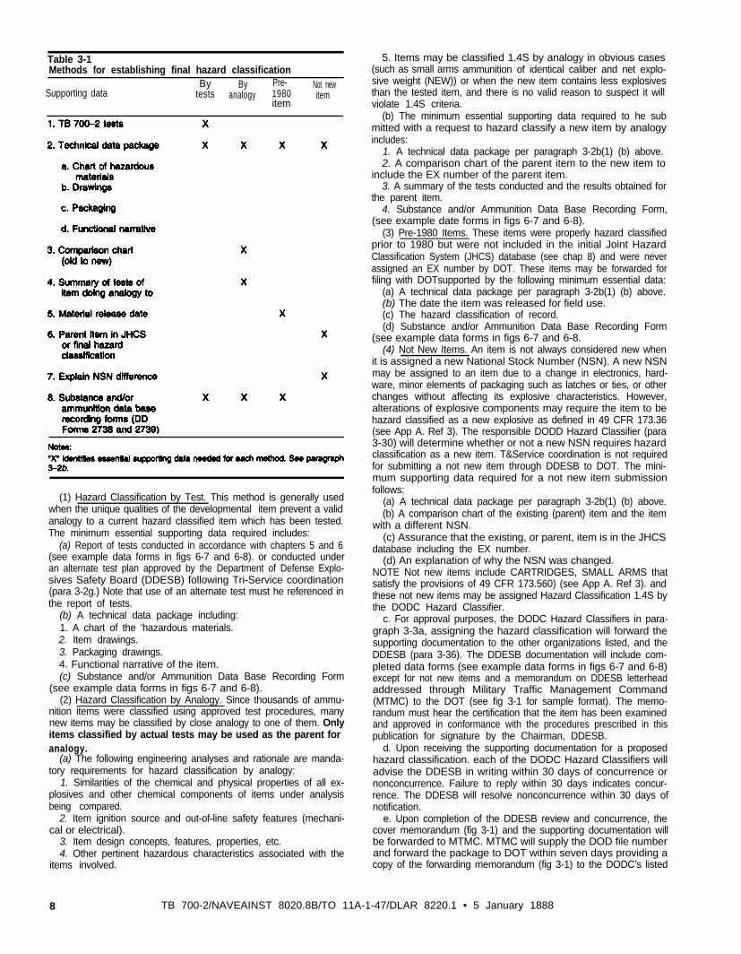
b. Them are four methods to support the final hazard classifica-tion for an item: Hazard classification by test; Hazard classificationby analogy; Pre-1980 items; and Not new items. The correct methoddepends upon the specific history and characteristics of the item tobe hazard classified. The forwarding correspondence should specifythe method selected for obtaining hazard classification. The essentialinformation required to support a hazard classification under eachmethod is provided in the following paragraphs. A condensed infor-mation chart in Table 3-1 identifies the essential supporting data foreach method.
TB 700-2/NAVSEAINST 8020.8B/TO 11A-1-47/DLAR 8220.1 • 5 January 1998 7
TB 700-2
Table 3-1Methods for establishing final hazard classification
By By Pre- Not newSupporting data tests analogy 1980 item
item
(1) Hazard Classification by Test. This method is generally usedwhen the unique qualities of the developmental item prevent a validanalogy to a current hazard classified item which has been tested.The minimum essential supporting data required includes:
(a) Report of tests conducted in accordance with chapters 5 and 6(see example data forms in figs 6-7 and 6-8). or conducted underan alternate test plan approved by the Department of Defense Explo-sives Safety Board (DDESB) following Tri-Service coordination(para 3-2g.) Note that use of an alternate test must he referenced inthe report of tests.
(b) A technical data package including:1. A chart of the ‘hazardous materials.2. Item drawings.3. Packaging drawings.4. Functional narrative of the item.(c) Substance and/or Ammunition Data Base Recording Form
(see example data forms in figs 6-7 and 6-8).(2) Hazard Classification by Analogy. Since thousands of ammu-
nition items were classified using approved test procedures, manynew items may be classified by close analogy to one of them. Onlyitems classified by actual tests may be used as the parent for analogy.
(a) The following engineering analyses and rationale are manda-tory requirements for hazard classification by analogy:
1. Similarities of the chemical and physical properties of all ex-plosives and other chemical components of items under analysisbeing compared.
2. Item ignition source and out-of-line safety features (mechani-cal or electrical).
3. Item design concepts, features, properties, etc.4. Other pertinent hazardous characteristics associated with the
items involved.
5. Items may be classified 1.4S by analogy in obvious cases(such as small arms ammunition of identical caliber and net explo-sive weight (NEW)) or when the new item contains less explosivesthan the tested item, and there is no valid reason to suspect it willviolate 1.4S criteria.
(b) The minimum essential supporting data required to he submitted with a request to hazard classify a new item by analogyincludes:
1. A technical data package per paragraph 3-2b(1) (b) above.2. A comparison chart of the parent item to the new item to
include the EX number of the parent item.3. A summary of the tests conducted and the results obtained for
the parent item.4. Substance and/or Ammunition Data Base Recording Form,
(see example date forms in figs 6-7 and 6-8).(3) Pre-1980 Items. These items were properly hazard classified
prior to 1980 but were not included in the initial Joint HazardClassification System (JHCS) database (see chap 8) and were neverassigned an EX number by DOT. These items may be forwarded forfiling with DOTsupported by the following minimum essential data:
(a) A technical data package per paragraph 3-2b(1) (b) above.(b) The date the item was released for field use.(c) The hazard classification of record.(d) Substance and/or Ammunition Data Base Recording Form
(see example data forms in figs 6-7 and 6-8.(4) Not New Items. An item is not always considered new when
it is assigned a new National Stock Number (NSN). A new NSNmay be assigned to an item due to a change in electronics, hard-ware, minor elements of packaging such as latches or ties, or otherchanges without affecting its explosive characteristics. However,alterations of explosive components may require the item to behazard classified as a new explosive as defined in 49 CFR 173.36(see App A. Ref 3). The responsible DODD Hazard Classifier (para3-30) will determine whether or not a new NSN requires hazardclassification as a new item. T&Service coordination is not requiredfor submitting a not new item through DDESB to DOT. The mini-mum supporting data required for a not new item submissionfollows:
(a) A technical data package per paragraph 3-2b(1) (b) above.(b) A comparison chart of the existing (parent) item and the item
with a different NSN.(c) Assurance that the existing, or parent, item is in the JHCS
database including the EX number.(d) An explanation of why the NSN was changed.
NOTE Not new items include CARTRIDGES, SMALL ARMS thatsatisfy the provisions of 49 CFR 173.560) (see App A. Ref 3). andthese not new items may be assigned Hazard Classification 1.4S bythe DODC Hazard Classifier.
c. For approval purposes, the DODC Hazard Classifiers in para-graph 3-3a, assigning the hazard classification will forward thesupporting documentation to the other organizations listed, and theDDESB (para 3-36). The DDESB documentation will include com-pleted data forms (see example data forms in figs 6-7 and 6-8)except for not new items and a memorandum on DDESB letterheadaddressed through Military Traffic Management Command(MTMC) to the DOT (see fig 3-1 for sample format). The memo-randum must hear the certification that the item has been examinedand approved in conformance with the procedures prescribed in thispublication for signature by the Chairman, DDESB.
d. Upon receiving the supporting documentation for a proposedhazard classification. each of the DODC Hazard Classifiers willadvise the DDESB in writing within 30 days of concurrence ornonconcurrence. Failure to reply within 30 days indicates concur-rence. The DDESB will resolve nonconcurrence within 30 days ofnotification.
e. Upon completion of the DDESB review and concurrence, thecover memorandum (fig 3-1) and the supporting documentation willbe forwarded to MTMC. MTMC will supply the DOD file numberand forward the package to DOT within seven days providing acopy of the forwarding memorandum (fig 3-1) to the DODC’s listed
8 TB 700-2/NAVEAINST 8020.8B/TO 11A-1-47/DLAR 8220.1 • 5 January 1888
in paragraph 3-3b. MTMC will assure that the responsible DODCand the DDESB are apprised of the EX number assigned by DOT.
f. The responsible DODC should invite other compments to ob-serve significant hazard classification tests.
g. When test requirements of this document cannot be met for aspecific item, the responsible DODC Hazard Classifier (para 3-30)will forward a proposed alternate test plan to the DDESB for reviewand approval, and to the other DODC Hazard Classifiers for coor-dination using the same procedures used for proposed hazard classi-fications (para 3-26). Alternate test plans may not be used withoutDDESB approval to avoid delays and potential retesting efforts.
3-3. Notification of classificationsa. The DODC offices of primary responsibiity for hazard classi-
fication are listed below.
D i r e c t o rU.S. Army Technical Center for Explosives SafetyATTN: SIOAC-ESTSavanna, IL 61074-9639
commanderNaval Ordnance CenterATTN: N71Farragut Hall. Building D-32323 Strauss AvenueIndian Head, MD 20640-5555
Air Force safety centerATTN: SEWV9700 Avenue GKirkland AFB, NM 87117-5670
b. The DODC responsible for determining the hazard classifica-tions will furnish notifications of classifications assigned and supporting documentation to the following:
(1) For concurrence:
DirectorU.S. Army Technical Center for Explosives SafetyATTN: SIOAC-ESTSavanna, IL 61074-9639
CommanderIndian Head DivisionNaval Surface Warfare CenterATTN: Code 04101 Strauss AvenueIndian Head, MD 20640-5035
Air Force Safety CenterATTN: SEWV9700 Avenue GKirtland AFB, NM 87117-5670
(2) For concurrence and transmittal through MTMC to DOT:
ChairmanDepartment of Defense Explosives Safety BoardHoffman Building I, Room 856C2461 Eisenhower AvenueAlexandria, VA 22331-0600
c. Figure 3-1 will be used as the format for DDESB signature.The DDESB letterhead stationary is used for this purpose and filledout by the DODC. Request the format be as exact as practicable.
d. For information. following assignment of the EX number,MTMC will furnish notification of final hazard classification (supporting documentation need not be furnished).
CommandantU.S. Coast GuardATTN: Hazardous Cargo Division2100 Second Street, S.W.Washington, DC 20593-0001
DirectorDefense Logistics AgencyATTN: AQCOICameron StationAlexandria, VA 22304-6190
TB 700-2/NAVSEAINST 8020.8B/TO 11A-1-47/DLAR 8220.1 • 5 January 1998 9
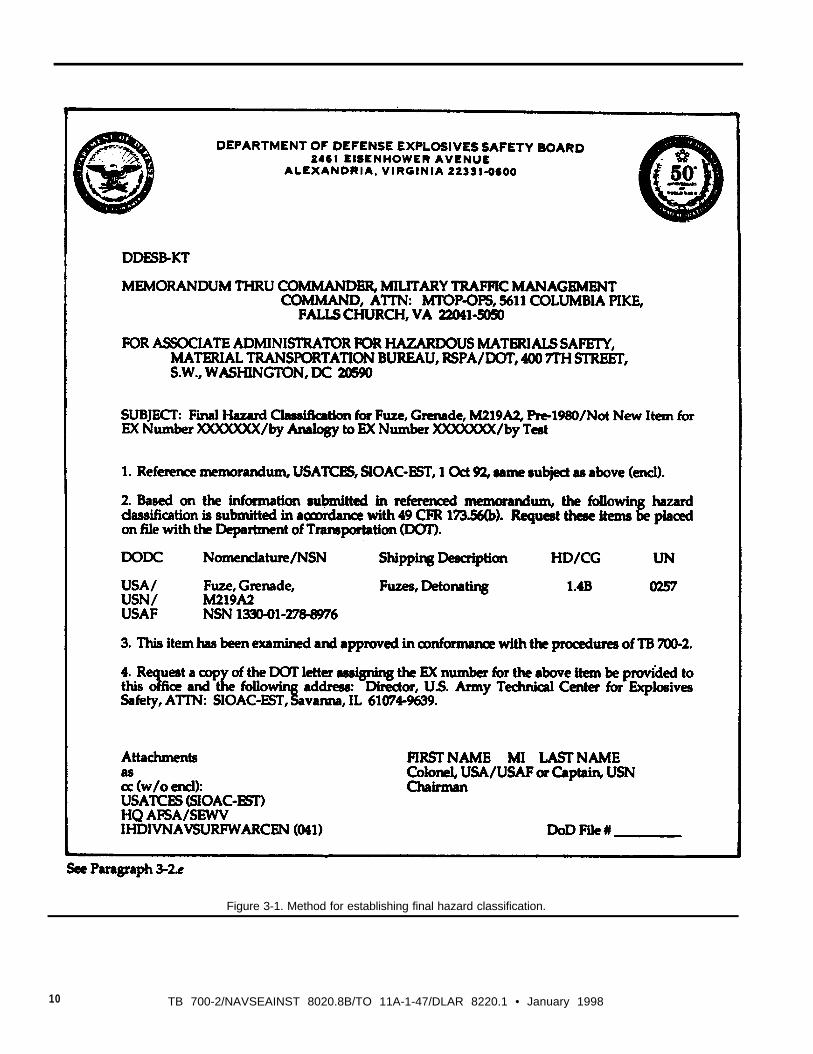
Figure 3-1. Method for establishing final hazard classification.
10 TB 700-2/NAVSEAINST 8020.8B/TO 11A-1-47/DLAR 8220.1 • January 1998
Chapter 4Hazard Classification
4-1. Scopea. The purpose of this chapter is to assure that DODCs employ
standard procedurea for the assignment of the hazard classificationsto ammunition and explosives based on the predominant hazard.Resultant assessments provide a means of readily identifying thehazard characteristics of ammunition (containing Class 1 material)and explosives through assignment of hazard categories establishedfor storage and transport as explained in paragraphs 4-2 through4-7.
b. The Department of Energy (DOE) is authorized by DOT 49CFR paragraph 173.56(b)(3) (App A, Ref 3) to examine, classifyand approve explosives in accordance with these hazard classifica-tion procedures as described in applicable DOE orders and manuals.
c. If an ammunition item is established to be non-Class 1 basedon predominant hazard (see para 1-6), then the tri-service coordi-nated DOD and DOE hazard classification must be assigned accord-ing to the properties of the predominant hazard in accordance with49 CFR 173 (App A, Ref 3). See NOTE in paragraph 3-10.
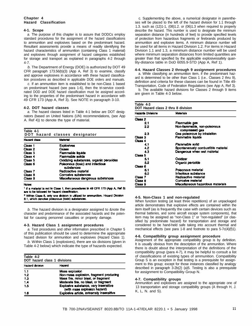
c. Supplementing the above, a numerical designator in parenthe-ses will be placed to the left of the hazard division for 1.1 through1.3. such as (12)1-1, (08)1.2. or (06)1.3 when required to properlydescribe the hazard. This number is used to designate the minimumseparation distance (in hundreds of feet) to provide specified levelsof protection from hazardous fragments or firebrands produced byammunition and explosive items. A minimum distance number willbe used for all items in Hazard Division 1.2. For items in HazardDivision 1.1 and 1.3, a minimum distance number will be usedwhere minimum separation distances from limited quantities aregreater than that specified by the applicable explosivessafety quan-tity-distance table in DoD 6055.9-STD (App A, Ref 1).
4-4. Hazard Classes 2 through 9 assignment proceduresa. While classifying an ammunition item, if the predominant haz-
ard is determined to be other than Class 1 (i.e.. Classes 2 thru 9),definition and criteria for these classes can be found in Title 49-Transportation, Code of Federation Regulations (see App A, Ref 3).
b. The available hazard divisions for Classes 2 through 9 itemsare given in Table 4-3 below.
Table 4-34-2. DOT hazard classes DOT Hazard class 2 thru 8 division
a. The hazard classes listed in Table 4-1 below are DOT desig-nators (based on United Nations (UN) recommendations, (see AppA. Ref 4)) to denote the type of material.
Table 4-1D O T h a z a r d c l a s s e s d e s i g n a t o r
b. The hazard division is a designator assigned to ¬e thecharacter and predominance of the associated hazards and the poten-tial for causing personnel casualties or property damage.
4-3. Hazard Class 1 assignment proceduresa. Test procedures and other information prescribed in Chapter 5
of this publication should be used to determine the appropriatehazard division for ammunition and explosives (Hazard Class 1).
b. Within Class 1 (explosives), there are six divisions (given inTable 4-2 below) which indicate the type of hazards expected.
4-5. Non-Class 1 and non-regulatedWhen function testing (at least three repetitions) of an unpackagedarticle demonstrates that explosive effects are contained within theitem itself (as is frequently the case with certain devices such asthermal batteries, and some aircraft escape system components), thatitem may be assigned as “non-Class 1” or "non-regulated” (or clas-sified by predominate hazard) for transportation and storage andconsidered to be hand-held safe taking into account thermal andmechanical effects (see para 1-8 and footnote to para 5-7c(4)(f)1).
Table 4-2DOT hazard class 1 divisions
4-6. Compatlbility group assignment procedureAssignment of the appropriate compatibility group is by definition.It is usually obvious from the description of the ammunition. Wherethere is doubt about the interpretation of the definitions of thecompatibility group (para 4-7), it may be helpful to consult a listof classifications of existing types of ammunition. CompatibilityGroup S is an exception in that testing is a prerequisite for assign-ment to this group; except for those instances classified by analogydescribed in paragraph 3-2b(2) (a)5. Testing is also a prerequisitefor assignment to Compatibility Group N.
4-7. Compatibility groupsAmmunition and explosives are assigned to the appropriate one of13 transportation and storage compatibility groups (A through H, J.K, L, N. and S).
TB 700-2/NAVSEAINST 8020.8B/TO 11A-1-47/lDLAR 8220.1 • 5 January 1998 11
a. Group A-initiating explosives. Packaged initiating explosivesthat have the necessary sensitivity to heat, friction, or percussion tomake them suitable for use as initiating elements in an explosivetrain. Examples are lead axide, lead styphnate, mercury fulminate,tetracene, and PETN.
b. Group B--detonators and similar initiating devices. Items con-taining initiating explosives that are designed to initiate or continuethe functioning of an explosive train. Examples are detonators, blas-ting caps, small arms primers, and fuzes without two or more safetyfeatures.
c. Group C-packaged propellants, propelling charges, and de-vices containing propellant with or without their means of ignition.Items that upon initiation will deflagrate or explode. Examples aresingle-, double-, triple-base, and composite propellants, rocketmotors (solid propellant), and ammunition with inert projectiles.
d. Group D-black powder, secondary high explosives (HE), andammunition containing secondary HE without its own means ofinitiation and without propelling charge. or ammunition containing aprimary explosive and two or mote effective features. Ammunitionand explosives that can be expected to explode or detonate whenany given item or component thereof is initiated. Examples am: bulkTNT, Composition B, black powder. wet RDX, bombs, projectiles,cluster bomb units (CBUs), depth charges, torpedo warheads, andfuzes with two or more safety featured.
e. Group E-ammunition containing HE without its own meansof initiation and with propelling charge (other than liquid). Ammu-nition or devices containing HE and containing propelling charges.Examples are artillery ammunition, rockets, or guided missiles.
f. Group F-ammunition containing HE with its own means ofinitiation and with a propelling charge (other than liquid) or withoutpropelling charge. HE ammunition or devices (fuxed) with or with-out propelling charges. Examples are grenades. sounding devices,and similar items having an in-line explosive train in the initiator.
g. Group G-pyrotechnic substances, fireworks, illuminating, in-cendiary, smoke including HC, or tear-producing munitions otherthan those munitions that are water activated or which contain whitephosphorus (WP) or flammable liquid or gel. Ammunition that,upon functioning, results in an incendiary, illumination, lachryma-tion. smoke, or sound effect. Examples are flares, signals. incendi-ary or illuminating ammunition, and other smoke- or tear-producingdevices and pyrotechnic substances.
h. Group H-ammunition containing both explosives and whitephosphorus. Ammunition in this group contains white phosphorusfillers that are spontaneously flammable when exposed to the atmos-phere. Examples are ammunition containing WP and PWP.
i. Group J-ammunition containing both explosives and flamma-ble liquids or gels. Ammunition in this group contains flammableliquids or gels other than those that are spontaneously flammablewhen exposed to water or the atmosphere. Examples are liquid- orgel-filled incendiary ammunition, fuel-air explosive (FAE) devices,flammable liquid-fueled missiles, and torpedoes.
j. Group K-ammunition containing both explosives and toxicchemical agents. Ammunition in this group contains chemicals spe-cifically designated for incapacitating effects more severe thanlachrymation. Examples are artillery or mortar ammunition, fuzed orunfuzed, grenades, and rockets or bombs filled with a lethal orincapacitating chemical agent
k. Group L.-ammunition and explosives not included in othercompatibility groups. Ammunition or explosives having characteris-tics that do not permit storage with other types of ammunition orkinds of explosives or dissimilar ammunition of this group. Exam-ples are water-activated substances, phosphides, and pyrophoric sub-stances and devices containing these substances; hypergolics andhypergolic prepackaged liquid-fueled rocket engines; TPA (thi-ckened TEA) and damaged or suspect ammunition of any group.*
l. Group N-ammunition containing only extremely insensitivedetonating substance (EJDS). Examples are bombs and warheads. Ifdissimilar Group N munitions are mixed together and have not been
tested to assure non-propagation, then the mixed munitions are con-sidered to be Hazard Division 1.2, compatibility Group D for pur-poses of transportation and storage.
m. Group S-ammunition presenting no significant hazard. Seeparagraphs 3-2b(4), 5-7c(4)(e) and (f), and 6-5b(7). Ammunitionthat is packaged or designed so that any hazardous effects arisingfrom accidental functioning are confined within the package. That isunless the package has been degraded by fire. in which case all blastor projection effects are limited to the extent that they do notSignificantly hinder firefighting or other emergency response effortsin the immediate vicinity (i.e., S meters) of the package. Examplesare thermal batteries, explosive switches or valves, and other ammu-nition items packaged to meet the criteria of Group S items.
*Ammunition/explosives presenting same or similar hazards withinthis group may be stored together. However, items with dissimilarhazards within this group must be kept separate and apart from allother items.
4-8. Assignment of DOT Identification number (UnitedNations number)A four-digit Arabic number for transport identification of an item isto be assigned. These numbers are listed in 49 CFR 100 TO 177paragraph 172, (see App A, Ref 3) which is for sale by the Superin-tendent of Documents, U.S. Government Printing Office, Mail StopSSOP, Washington, DC 20402-9328. These numbers are also givenin the UN publication entitled “Recommendations on the Transportof Dangerous Goods,” (see App A, Ref 4). which is available fromthe United Nations Sales Section, New York, NY 10017.
4-9. Explosive weights for Class 1 Itemsa. High Explosive Weight (HEW). The total weight of all Hazard
Division 1.1 material contained in an item.b. Net Propellant Weight (NPW). The total weight of Hazard
Division 1.3 material contained in an item.c. Net Explosive Weight (NEW). NEW = HEW + NPW, The
total weight of all Class 1 material in an item, stack of items, ship,vehicle, aircraft, cubicle or building. For instance, the NEW of anentire ship’s cargo is required on the manifest for shipment underthe International Maritime Dangerous Goods Code (IMDG).
d. Net Explosive Weight for Q-D (NEWQD). NEWQD = NEWunless testing has been conducted (see paras 6-1a and 62). Basedon testing, the NEWQD may include a contribution (less than orequal to 100%) from Hazard Division 1.3 material when the HazardDivision 1.1 material has been functioned. The test protocol and thedetermination of NEWQD requires approval by the DDESB. TheNEWQD may not be acceptable for transportation over the high-ways or aboard ships. The value of applying NEWQD occurs instorage configurations and when items are deployed.NOTE: Quantity distance (Q-D) is defined in Chapter 2.
4-10. Storage without lnterim hazard classificationsOccasions may arise, particularly in manufacturing and laboratoryenvironments, that dictate storage of explosive samples or itemswithout interim hazard classifications. In such circumstances, thecognizant DODC Hazard Classifier will establish procedures forassigning hazard classification and compatibility group for storage.This material will not be transported from the installation or devel-opment location until the necessary interim hazard classificationsare received. See paragraph 1-7 for an exception for transportingsmall explosive samples.
Chapter 5Tests
5-1. Hazard classification test protocola. Introduction. This chapter prescribes the tests that are required
by 49 CFR (App A, Ref 3) for transport purposes and by STANAG4123, (App A, Ref 2) and DoD 6055-9-STD (App A. Ref 1) for the
12 TB 700-20/NAVSEAINST 8020.8B/TO 11A-1-47/DLAR 8220.1 • 6 January 1998
establishment of storage hazard classifications. The test require-ments described conform to the tests recommended by the UnitedNations (UN) Committee of Experts on the Transport of DangerousGoods which are documented in Recommendations on the Transportof Dangerous Goods, Tests and Criteria (see App A, Ref 6). Thetests are divided into seven series which are described below:
(1) UN Series 1-Detonability tests for new substances.(2) UN Series 2-Insensitivity tests for new substances.(3) UN Series 3-Hazard tests for handling and transporting new
substances.(4) UN Series 4-Hazard tests for handling and transporting new
articles, packaged articles and packaged substances.(5) UN Series S-Hazard Division 1.5 tests (very insensitive
explosive substance (with a mass explosion hazard)).(6) UN Series 6-Hazard Classification tests (Hazard Divisions
1.1. 1.2, 1.3, and 1.4).(7) UN Series 7-Hazard Division 1.6 tests (extremely insensi-
tive explosive articles which contain extremely insensitive detonat-ing substances (EIDS)).
b. Test protocol. The general scheme for hazard classifying ex-plosive substances and articles is given in Figure 5-1. United Statestest options are selected from the UN recommendations for the DoDand DOT test protocol. All hazard classification tests referenced inthis document are referred to by the UN designation (numberingsystem), such as Test l(a) (iii). Use of optional tests in the UNprotocol is acceptable. Note that a “negative (-)” response to a testindicates a “pass” response whereas a “positive (+)” response indi-cates a "fail" response.
(1) Optional substance tests. UN Series 1 and Series 2 tests listedbelow are not required for DOD substances manufactured with theview to producing a practical explosive or pyrotechnic effect (seeBox 2 in fig 5-1).
(a) Test 1(a) (iii)-Gap Test for Solids and Liquids (para 5-2a).(b) Test 1(b) (ii)-Internal Ignition Test (para 5-26).(c) Test 1(b) (iii)-Slow Cookoff Bomb (SCB) Test (para 5-2c).(d) Test 2(a) (iii)-Gap Test for Solids and Liquids (para 5-3a).(e) Test 2(b) (ii)-Internal Ignition Test (para 5-36).(f) Test 2(b) (iv)-Slow Cookoff Bomb (SCB) (para 5-3c).(2) Mandatory substance tests. The acceptance procedure for any
substance designed to have an explosive effect begins with theapplication of UN Test Series 3. Note that Test Series 1 and 2 arenot required for substances designed to have an explosive effect. Asubstance is forbidden for transport if a positive (+) response isobtained with any of the following tests:
(a) Test 3(a) (Q-Bureau of Explosives Impact Machine Test(para 54).
(b) Test 3(b) (iii )--ABL Friction Test (para 5-4b).(c) Test 3(c)-Thermal Stability Test at 75°C (para 5-4c).(d) Test 3(d) (i)-Small-Scale Burning Test (para 5-4d).(3) Explosive article, packaged or unpackaged, or a packaged
explosive substance tests.(a) Substances that fail Test 3(c) (thermal stability) are forbidden.
For this reason, it is recommended that test 3 (c)-be the first testconducted. Substances that fail Test 3(a) (i) (impact), Test 3(b) (iii)(friction), and/or Test 3(d) (i) (small-scale burn) may be encapsu-lated and/or packaged (Box 13, fig 5-1) and subjected to Test 4(b)(ii) (12 meter drop test) for possible acceptance into Class 1.
(b) New articles must be subjected to Test Series 4. when appro-priate, for possible acceptance into Class 1. Items are forbidden fortransport if the appropriate Series 4 tests (listed below) are notconducted, or if a positive (+) test response is obtained.Note. It is appropriate (mandarory) to conduct 4(a) on an article or packagedarticle when a substance used in the article has not passed Test 3(c). It isappropriate (mandatory) to conduct Test 4(b)(i) (for liquids) or 4(b)(ii) (forsolids) on articles. packaged articles, or packaged substances when sub-stances in the items have not passed Tests 3(a)(i). 3(b)(iii). and 3(d)(i). orequivalent tests.
1. Test 4(a)-Thermal Stability Test for Articles and PackagedArticles (para 5-5a)does not apply to packaged substances. Ther-mal stability testing of an article or packaged article is appropriate if
the new article contains a substance that has not been subject to Test3(c). or if the chemical compatibility of explosive substances andthe materials with which they are in contact has not beenestablished.
2. Test 4(b)(i)-Steel Tube Drop Test for Liquids (para 5-5b).3. Test 4(b) (ii)-Twelve Meter Drop Test for Articles and Solid
Substances (para 5-5c).(4) Hazard Division 1.5 explosives tests. A substance may not be
classified as a Hazard Division 1.5 explosive if a positive (+) re-sponse is obtained with any of the tests in Series 3 (listed above) orwith any of the following tests in Series 5:
(a) Test 5(a)-Cap Sensitivity Test (para 5-6a).(b) Test 5(b) (ii)-DDT Test (para 5-6b).(c) Test 5(c )--External Fire Test for Hazard Division 1.5 (para
5-6c).(d) Test 5(d)-Princess Incendiary Spark Test (para 5-6d).(5) Hazard Divisions 1.1, 1.2, 1.3, and 1.4 tests. Explosive arti-
cles, ‘packaged or unpackaged or packaged explosive substances areclassified among Hazard Divisions 1.1, 1.2, 1.3 and 1.4 according totheir responses in Test Series 6 as described in paragraph 5-7. Thetests in Series 6 are:
(a) Test 6(a)-Single Package Test (para 5-7a).(b) Test 6(b)--Stack Test (para 5-7b).(c) Test 6(c )-External Fire (Bonfire) Test (para 5-7c).(d) Approved alternate test procedures for Hazard Division 1.2
and for classifying solid rocket motors are provided in paragraphs6-6band 6-6c, respectively. Also, guidance on airblast data collec-tion, airblast hazard evaluation and interpretation, fragment collec-tion, fragment hazard evaluation and interpretation, and thermaleffects data collection, evaluation and interpretation is given inChapter 6.
(e) For purposes of hazard classification for DOD storage of liq-uid explosives, an additional test is required; The Flash Point Test(para 5-9). Liquid explosives with a flash point below 95°C (posi-tive (+) response)) are forbidden for storage.
(6) Hazard Division 1.6 tests.(a) A substance intended for use as an explosive load of a Haz-
ard Division 1.6 article may not have a positive (+) response withany of the substance tests in Test Series 3 (listed above) or TestSeries 7 and is classified as an extremely insensitive detonatingsubstance (EIDS). The UN, DOT, and the DOD consider bulk EIDSas a Hazard Division 1.5 substance.Note. If the EIDS is stored or transported separately as Hazard Division 1.5.then the EIDS must be pass Test Series 5. See comments below for storageof packaged EIDS "articles.” The Series 7 substance tests are listed below(note that the Friability Test is an approved alternate test for both the SusanImpact Test and the EIDS Bullet Impact Test):
1. Test 7(a)-EIDS Cap Test (para 5-80).2. Test 7(b)-EIDS Gap Test (para 5-8b).3. Test 7(c) (i)-Susan Impact Test (para 5-8c); or,4. Test 7(c) (ii)-Friability Test (para 5-8d).5. Test 7(d) (i)-EIDS Bullet Impact Test (para 5-8e)) or,6. Test 7(d) (ii)-Friability Test (para 5-8d).7. Test 7(e)-EIDS External Fire Test (para 5-8f).8. Test 7(f)-EIDS Slow Cookoff Test (para 5-8g).(b) An article intended to be a Hazard Division 1.6 article must
contain only EIDS and may not have a positive (t) response withany of the Test Series 7 article tests. Note that packaged bulkElDS that satisfies these same criteria may be classified as aHazard Division 1.6 article for storage. The Series 7 article testsare listed below.
1. Test 7(g)-1.6 Article External Fire Test (para 5-8h).2. Test 7(h)-1.6 Article Slow Cookoff Test (para 5-8i).3. Test 7(j)-1.6 Article Bullet Impact Test (para 5-8j).4. Test 7(k)-1.6 Article Propagation Test (para 5-8R).(7) Lethal and incapacitating chemical munitions. These items
will be tested under criteria unique to chemical weapons.
5-2. UN Test Series 1 (optional)These tests are conducted to answer the question “Is it an explosive
TB 700-2/NAVSEAINST 8020.8B/TO 11A-1-47/DLAR 8220.1 • 5 January 1998 13
substance?” The test series includes shock and combustion or ther-mal tests. Note that the Internal Ignition Test-l(b) (ii) (para 5-2.b)and the Slow Cookoff Bomb (SCB) Test-l(b) (iii) (para 5-2c) arealternate tests.Note. Test Series 1 results cannot be used to remove a “substance manufac-tured with the view to producing a practical explosive or pyrotechnic ef-fect" from Class 1 5-1)
a. Gap test for solids and liquids--(UN Test l(a) (iii)).(1) lntroduction. test is designed to determine whether a
liquid or solid substance will maintain a stable detonation and. if itdoes. measure its shock sensitivity. The sample is loaded in a steeltube of specific dimensions and is subjected to the shock wavegenerated by the detonation of a pentolite booster.
(2) Apparatus and materials.(a) Solids. The apparatus for the Gap Test for solids is shown in
Figure 5-2. The test sample is contained in a seamless carbon steelcylinder. Spacers are used to separate a mild steel witness platefrom the sample tubing at the upper end. The bottom of the cylinderis closed with two layers of polyethylene sheets held in place withgum rubber bands and polyvinylchloride electrical insulating tape.There is no other gap between the pentolite booster and the testsample. A continuous velocity of detonation probe (see App A, Ref7) made of thin aluminum tube with an axial resistance wire havinga resistance of 3.0 ohms/cm (7.6 ohms/in) is mounted on the wall ofthe sample tubing. The outer tubing of the probe is crimped againstthe inner wire at the lower end forming a resistor. As a detonationwave moves up the tubing, the outer wall crushed against innerwire, shortening the effective length and changing the resistance ofthe wire. If a constant current (usually 0.06 amperes) is made toflow between the outer and inner conductors, the voltage betweenthem is proportional to the effective length and can be recorded as afunction of time using an oscilloscope. The slope of the oscilloscopetrace is thus proportional to the velocity of the shock wave.
(b) Liquids: The apparatus for the Gap Test for liquids is thesame as that for solids except that a better method of sealing thebottom of the tube must be used. The recommended method is tofuse a 0.05 to 0.08 mm (0.002 to 0.003 inch) thick sheet (thickersheets may adversely affect results) of fluorocarbon or other com-patible plastic to the tube. Any suitable technique may be used,however, each tube should be checked for leaks before use. Theexperimental setup is shown in Figure 5-3. For liquids which maybe sensitive to adiabatic compression of bubbles, the tests should beconducted with air bubbles being injected near the bottom of thesample at the time of test. Air is supplied at a pressure of 30 to 100kPa (4.4 to 14.5 psi) to obtain 8 flow rate of 1.2 liters/minute (7.1 x10⁴ cubic feet/second). The bubbles may be created by a smallplastic frit or by holes punched in a loop of vinyl plastic tubing. Thetubing supplying the frit or forming the loop should be about 2.0mm (0.08 in) OD such as for medical catheterization. Holes may bemade by perforating the tubing forming the loop with a 1.3 mm(0.051 in) diameter needle and allowing the elastic nature of thetubing to contract the hole. The number of holes and amount ofbubbling should be consistent for all tests of a sample or for asufficient number of tests to establish repeatability. The submergedend to the bubbler shall be plugged with a suitable cement. The airsupply tubing may be introduced from the top of the sample tube orthrough a hole through the side near the bottom and sealed with asuitable cement. Where it is suspected the sample may react withthe metal of the teat gap tube, the interior of the tube should becoated with suitable material such as fluorocarbon resin spray.
(3) Procedure. The sample is loaded to the top of the steel tube.For liquid samples. adequate ullage should be allowed. Solid sam-ples are loaded to the density attained by tapping the cylinder untilfurther settling becomes imperceptible. The sample is tested at am-bient conditions (25 +/- 2°C) and is subjected to the shock wavegenerated by the detonation of a 165 g (2550 grain) pentolite (50/50PETN/TNT) pellet. The pentolite pellet is in intimate contact withthe bottom of the test sample and initiated with a standard No. 8detonator shown in Figure 5-4. The detonator is held in place by a
cork detonator holder. Three tests should be performed on eachsample.
(4) Criteria and method of assessing results.(a) The criteria for propagation are:1. A stable propagation velocity greater than the velocity of
sound in the substance.2. A hole is punched through the witness plate.3. The sample tube is fragmented along its entire length.(b) The overall test results are considered positive (+) if any two
of the three criteria listed above are met.6. Internal ignition test (UN Teat 1(b)(ii)).(1) Introduction. The Internal Ignition Test is designed to deter-
mine the response of substances to rapidly rising temperatures andpressures.
(2) Apparatus and material.(a) The experimental arrangement is shown in Figure 5-5. The
sample of the substance to be tested is contained in a steel pipewhich is capped on both ends. An igniter consisting of black powder(100% passed through a No. 20 sieve, 0.84 mm (0.033 in) and100% retained by a No. 50 sieve, 0.297 mm (0.0117 in)) is locatedat the center of the sample vessel.
(b) The igniter assembly consists of a cylindrical container madewith 0.54 mm (0.021 in) thick cellulose acetate held together by twolayers of nylon filament reinforced cellulose acetate tape. The ig-niter capsule contains a small loop formed from a 25.4 mm (1 0. in)length of nickel-chromium alloy wire 0.3 mm (0.012 in) in diameterand hating a resistance of 0.35 ohms. This loop is attached to twoinsulated tinned copper leading wires. The tinned copper wires are0.66 mm (0.024 in) in diameter with a 1.3 mm (0.051 in) outsidediameter (including insulation). These wires are installed throughsmall holes in the pipe which are sealed with epoxy resin.
(3) Procedure. The sample is loaded into the pipe to a height of230 mm (9 in). A 20 g (310 grain) igniter is inserted into the centerof the pipe, the leads are pulled taut and then sealed with epoxyresin. The remainder of the sample is then loaded and the top capscrewed on. The igniter is fired by applying a 20 V, 15 amperecurrent. Three tests ate petformed on each substance.
(4) Criteria and method of assessing results. The criteria for thelnternal Ignition Test are:
(a) Positive (+) result if either the pipe or one of the end caps isfragmented into at least two distinct pieces separated from the pipe.
(6) Negative (-) result if the reaction is no more violent than thepipe is either just split (laid open, not fragmented) or the end capsare only distorted.
c. Slow cookoff bomb (SCB) test (UN Teat 1(b) (iii)).(1) Introduction. The Slow Cookoff Bomb (SCB) Test simulates
transport and storage situations which could expose substances’ toslow external heating.
(2) Apparatus and material. The experimental arrangement isshown in Figure 5-6. The sample of substance to be tested iscontained in a steel vessel. Two-400-watt electric heaters are fas-tened to the steel vessel. The vessel has a steel cover with two feed-through fittings for the thermocouple leads and for a pressure take-off. The mounting frame consists of two steel witness plates withfour bolts that clamp the SCB vessel between them. The vessel isinstrumented with one or two plate-type thermocouples; one is spotwelded to the center of the vessel wall. and another, if needed, isplaced in the center of the substance that is tested. The plate-typethermocouples consist of a 0.3 mm (0.01 in) thick nichrome ribbonapproximately 10 mm (0.4 in) square, with the thermocouple wiresfanned out and individually spot welded to the nichrome. Plate-typerather than bead-type thermocouples are used in the SCB sinceplate-type thermocouples give faster response and more representa-tive measurement of the temperature of the interfaces.
(3) Procedure. Test substance in the form of a solid, liquid, slurryor powder to loaded of the steel vessel of the SCB unit.Sufficient ullage should be allowed so that the vessel will not beliquid full at 400%. The SCB unit is assembled and placed in a safetesting bay; it is heated by connecting the two 400 watt heaters to120 VAC or 120 VDC. Strip-chart recorders can be used to recordthe temperature of the SCB unit and the time to cookoff. The
14 TB 700-2/NAVSEAINST 8020.8B/TO 11A-1-47/DlAR 8220.1 • 5 January 1998
heating rate is maintained at 3°C/Min. The test is started at 25° +/-3°C and continued until a reaction occurs or a temperature of 400°Cis reached.
(4) Criteria and method of assessing results. Time and tempera-ture of a substance reaction (cookoff) are taken from the chartrecords (for information purposes only), and an assessment of theseverity of the reaction is made from the number and condition ofthe vessel fragments and the condition of the witness plate, Levelsof reaction to be identified are:
(a) The result of the test is considered negative (-) if the SCB isin one piece (not ruptured or fragmented) and the witness plates arenot deformed or pun-
(6) The result of the test is considered positive (+) if any of thefollowing occurs:
1. SCB apparatus is ruptured.2. SCB apparatus is fragmented.3. Witness plate is deformed.4. Witness plate is punctured.
5-3. UN Test Series 2 (optional)These tests are conducted to answer the question "Is the substancetoo insensitive for acceptance into Class 1?" The test series includesshock and combustion or thermal tests used in Test Series 1 withless stringent pass/fail criteria. Note that the Internal Ignition Test-2(b) (ii) (para 5-36) and the Slow Cookoff Bomb (SCB) Test-2(b)(iv) (para 5-3c) are alternate tests.Note. Test Series 2 results cannot be used to remove a “substance manufac-tured with the view to producing a practical explosive or pyrotechnic effect”from Class 1 (see fig 5-1).
a. Gap test for solids and liquids (UN Test 2(a) (iii)).(1) Introduction. The test is designed to measure the shock sensi-
tivity and detonation propagation of a solid or liquid substance tod&ermine whether the substance may be too insensitive for accept-ance into Class 1. The sample is loaded in a steel tube of specificdimensions and is subjected to the shock wave generated by thedetonation of a pentolite booster with a 5.08 cm (2.0 in - 200 cards)cast PMMA (polymethyl methacrylate) gap (plexiglass or equiva-lent) between the booster and the test sample.
(2) Apparatus and materials. The apparatus for solid substances isshown in Figure 5-7 and for liquid substances in Figure 5-8. Thistest is identical to the test of paragraph 5-2a except for the additionof a 5.08 cm (2.0 in) diameter by 5.08 cm (2.0 in) thick plexiglassbuffer between the 165 g (2550 gram) pentolite donor and substancesample. For more details refer to paragraph 5-2a(2).
(3) Procedure. The procedure is the same as that described forparagraph 5-2a(3).
(4) Criteria and method of assessing results.(a) The criteria for propagation are as follows:1. A stable propagation velocity greater than the velocity of
sound in the substance;2. A hole is punched through the witness plate;3. The sample tube is fragmented along its entire length.(b) The overall test results are considered positive (+) if any two
of the three criteria are met.b. Internal ignition test (UN Test 2(b) (ii)).(1) Introduction. The Internal Ignition Test for Test Series 2 uses
the same apparatus as Test l(b) (ii) with the exception that a 10 g(154 gram) instead of a 20 g (310 grain) fffg black powder igniter isUsed.
(2) Apparatus and materials. The test configuration (fig 5-5 andpara 5-2b(2) with an igniter capsule of 3.2 cm (1.25 in) long isused.
(3) Procedure. The procedure of paragraph 5-2b(3) is used.(4) Criteria and method of assessing results. The criteria for the
Internal Ignition Test are:(a) Positive (+) result if either the pipe or one of the end caps is
fragmented into at least two distinct pieces separated from the pipe.(b) Negative (-) result if the pipe is either split (laid open) or the
end caps are distorted.c. Slow cookoff bomb (SCB) (UN Teat 2(b) (iv)).
(1) Introduction. The Slow Cookoff Bomb (SCB) Test experi-mental arrangement is shown in Figure 5-6.
(2) Apparatus and materials. The test is conducted with the appa-ratus described in paragraph 5-2c(2).
(3) Procedure. The test is conducted in accordance with the pro-cedures described in paragraph 5-2c(3).
(4) Criteria and method-of assessing results. Time and tempera-ture of a substance reaction (cookoff) are taken from the chartrecords and an assessment of the severity of the reaction is madefrom the number and condition of the vessel fragments and thecondition of the witness plates. Levels of reaction to be identifiedare:
(a) The result of the test is considered negative (-) if the SCBapparatus is in one piece. The apparatus may be ruptured but thewitness plates cannot he deformed or punctured.
(b) Tbe result of the test is considered positive (+) if any of thefollowing occurs:
1. SCB apparatus is fragmented.2. Witness plate is deformed.3. Witness plate is punctured.
5-4. Teat Series 3 (mandatory)These tests are conducted to answer the question "Is the substancetoo hazardous for transport (in the form tested)?” The test seriesincludes substance sensitivity tests for mechanical stimuli (impactand friction) and for heat and flame.
a Bureau of Explosives impact machine (UN Test 3(a) (i)).(1) Introduction. This test is designed to measure the sensitivity
of the substance to mechanical stimuli involving normal impact todetermine if the substance is too hazardous to &sport. It is’ appli-cable to solid and liquid substances by using two different sampleassemblies.
(2) Apparatus and materials. A drawing of the apparatus for theimpact test is shown in Figure 5-9. The apparatus is designed sothat a weight is free to fall between two parallel cylindrical guiderods from variable heights. The weight strikes a plunger-and-plugassembly which is in contact with the substance sample. The sub-stance sample is placed on a die-and-anvil assembly confined in acylindrical casing whose inside diameter is just sufftcient to permitfree movement of the plunger and plug. The plunger, plug, die,casing and anvil are hardened tool steel of hardness 50-55 on theRockwell C scale and the mating surfaces and the surfaces in con-tact with the sample have a finish of 0.8 microns (32 micro-inches).The sample holder diameter is 5.1 mm (0.20 inches).
(a) Solid substances. The sample assembly for a solid substanceis shown in Fiqure 5-10.
(b) Liquid substances. The sample assembly for liquid substancesis shown in Figure 5-11.
(3) Procedure.(a) Solids. Ten milligrams of the solid substance is loaded onto
the die The anvil and die are placed in the sample housing and thecasing screwed down over them. The plug and plunger are theninserted on top of the sample. The drop weight is raised to thedesired height and released. Ten measurements are performed at thespecified drop height for each test sample. Either RDX or HMX isused as the reference explosive for evaluating the test results foreach test series. Report the RDX or HMX calibration results alongwith the sample test results.
(b) Liquids. The rebound sleeve, the intermediate pin, and thestriker are assembled in the striker housing. A copper cup is placedin a cup positioning block (not shown in fig 5-11) and one drop ofthe liquid substance is placed in the cup. The housing and itscomponents are placed over the top of the cup positioning block.The end of the striker slips partway into the cup, but is prevented bythe cup positioning block from actually touching the liquid in thecup. When the striker housing is lifted from the positioning block,the cup is held on the end of the striker by friction. The strikerhousing is then screwed down into the anvil housing and the dimen-sions of the tools are such that the bottom of the copper cup justtouches the anvil when the striker housing is screwed in hand-tight.The whole unit is then placed in the same drop weight mechanism
TB 700-2/NAVSEAINST 8020.8B/TO 11A-1-47/DLAR 8220.1 • 5 January 1998 15

which is used with the Bureau of Explosives’ solid impact tester.For liquids. only one drop height is used. This is 25.40 cm (10inches). The teat is also conducted with the liquid absorbed in apiece of filter paper placed in the copper cup. Ten measurements areperfomed for each sample.
(4) Criteria and method of assessing results.(a) Solids. The criteria used in the interpretation of this test for
solids is that a measurement is considered positive if either anaudible report or flame is observed. A sample is considered impactsensitive at a specific drop height if a flame or report is observed inat least 50% of the test trials. A sample which shows impact sensi-tiveness at a drop height of 10.16 cm (4.0 inches) or less (a positive(+) response) is considered too sensitive for transport.
(b) Liquids. The criterion used in the interpretation of this test forliquids is that a measurement is considered positive if either anaudible report or smoke is observed in one of 10 test trials. Anyliquid explosive which fails this test at a drop height of 25.4 cm(10.0 inches) or less (a positive (+) response) is considered toosensitive for transport.
b. ABL friction test (UN Test 3(b) (iii)).(1) Introduction. This test determines the sensitivity of substances
to friction. The test substance is subjected to vertical compressionforce under a non-rotating wheel, while the substance is moved in ahorizontal direction on a sliding anvil. It is intended for both liquidand solid substances.
(2) Apparatus and materials. Figure 5-12 illustrates the appara-tus. The wheel and anvil are constructed of steel with a finish of1.52 micron (60 micro-inches). Force is applied hydraulicallythrough the non-rotating wheel to the sample which rests on theanvil. A pendulum impacting on the edge of the anvil propels theanvil at a known velocity, perpendicular to the compressive forcethat is applied to the sample. Normally, the anvil slides 2.54 cm (1.0in). The compressive force is measured by a gauge. The initialvelocity is determined by calibration.
(3) Procedure. A sample of test substance at 25°C. and in a thinuniform layer (equivalent to one particle thickness for solids basedon largest particle size in distribution) is placed on the anvil, underthe wheel, 0.64 cm (0.25 in) wide, and extending 2.54 cm (1.0 in)along the sliding contact surface. The wheel is lowered onto thesubstance and force is applied to the wheel. An initial force of 4450N (1,000 lb) is typical. In practice the force is changed in incre-ments where the lower value is 75% of the higher value. Maximumvalues of 8000 N (1,800 lb) and minimum of 44 N (10 lb) are used.A velocity of 0.9 m/sec (3 ft/sec) is a typical choice, althoughincreasing or decreasing velocity in increments of 0.3 m/sec (1 ft/sec) or more may be found useful in additional comparisons. Thevelocity is changed simply by altering the pendulum angle fromvertical from which the pendulum is released. (Thirty degree ap-proximates to 0.9 m/sec (3 ft/sec) slide velocity.)) A new sample isused on each trial, with cleaning of the anvil done between trials.An iterative procedure is used to determine the highest compressiveforce at which no positive (+) results are obtained in 20 trials. Thisvalue is considered the Threshold of Initiation (TIL). Dry pen-tacrythrite lentranitrate (PETN) is used as a reference explosive forevaluating the test results. Report the PETN results along with thesample results.
(4) Criteria and method of assessing results.(a) A trial is considered positive (+) if any one of the following
results is obtained:1. Visible sparks.2. Visible flame.3. Audible explosion.4. Loud crackling noise.5. Detection of reaction products by a gas analyzer.(b) Discoloration of the sample holder, crepitation (i.e., subdued
cracking due to crumbling of the sample), or slight odor in theabsence of indicators given by paragraph 5-4b(4) (a) above, are notconsidered positive (+) results.
(c) A substance with friction sensitivity equal to or greater thandry PETN. i.e., lower compressive force, is considered a positive (+)
result and is too sensitive for transport. PETN has a TIL of 184 N(41.4 lb) at 0.9 m/sec (3 ft/sec).
c. Thermal stability test at 75°C (UN Test 3 (c)).(1) Introduction. This test is designed to measure the stability of
the substance when subjected to elevated thermal conditions to de-termine if the substance is too hazardous to transport in the state inwhich it was tested.
(2) Apparatus and materials.(a) Apparatus. An oven is required for this test. If an electric
oven is used, the heating elements shall be isolated from the testvolume. The oven should be equipped with dual controls or a hightemperature cutoff feature to preclude thermal runaway if the pri-mary control fails. The control system should maintain the oventemperature at 75 +/- 2°C. The oven should be vented to allowvapors to escape. If it becomes necessary to run the second part ofthe test, additional apparatus as shown in Figure 5-13 is required.The additional apparatus is two flat bottomed glass tubes quippedwith pressure resisting stoppers. three thermocouples and a recorder.
(b) Materials. For-the second part of the test, an inert materialwith physical and thermal properties similar to those of the testsubstance will be used for the reference material.
(3) Procedure. The test is divided into two parts. The first part isused to determine if a sample shows obvious thermal instability byvisual evidence of ignition, explosion, significant color change indi-cating some reaction or weight loss. The second part is used only inthose cases where the first part does not provide a definite conclu-sion regarding the stability. In the second part, the thermocouple andrecorder apparatus described is used to measure any self-heating ofthe sample.
(a) Thermal stability. A substance sample of up to 50 g (770grains) is transferred to the tared beaker, covered and weighed. Thebeaker with cover is placed in the oven and heated at 75°C for 48hours. Unless an ignition or explosion occurs in the sample andterminates the test, the beaker is removed after the heating period,cooled and weighed. The volatility (weight loss as a percentage ofthe sample weight) is calculated. Any loss greater than expectedfrom loss of moisture shall be regarded as possible evidence ofinstability requiring testing for severity of instability (para5-4c(3)(b)). In dealing with an unknown substance, several screen-ing tests with a sample size much less than SO g (770 grains) areperformed to understand the behavior of the substance,
(b) Severity of instability. A 100 g (or 1.00cm3) (1.540 grain (6.1in3)) sample is dated in one tube and the same quantity of refer-ence substance is placed in the other. Thermocouples T1 and T2 areinserted into the tubes at half-height of the materials. If the ther-mocouples are not inert with respect to both the substance beingtested and the reference substance, they must be enclosed in sheathswhich are inert. Thermocouple T3 and the covered tubes are placedin the oven as shown in Figure 5-13. The temperature difference (ifany) between test sample and reference is measured for 48 hoursafter the sample and reference substance reach 75°C. Unless anignition or explosion occurs, the sample tube is removed, cooled inthe desiccator and weighed. Evidence of decomposition of the sam-ple is noted.
(4) Criteria and method of assessing results.(a) Thermal instability A test result is considered failing (posi-
tive (+)) if ignition or explosion occurs and passing (negative (-)) ifno decomposition has occurred. Any decomposition other than ml-nor surface discoloration from oxidation requires the second part ofthe test to be conducted.
(b) Severity of instability. The sample is considered thermallyunstable (positive (+) response - failing) if a temperature difference(i.e., self-heating) of +3°C of the sample (for a minimum time of tenseconds) is recorded. If no ignition or explosion of self heating of3°C or greater is recorded in the test, but self-heating of less than3°C T is noted, additional tests and/or evaluation may be required todetermine thermal stability.
d. Small-scale burning test (UN Test 3(d) (i)).(1) Introduction. A Small-Scale Burning Test is used to deter-
mine if small quantities of substances transition from deflagration todetonation when unconfined.
16 TB 700-2/NAVSEAINST 8020.8B/TO 11A-1-47/DLAR 8220.1 • 5 January 1998
(2) Apparatus and materials. Figure 5-14 shows the kerosene-soaked sawdust bed and plastic beaker to hold the substance. Igni-tion of the sawdust bed is accomplished with an appropriate electricigniter.
(3) Procedure. One hundred and twenty-five grams (1930 grams)of the substance under test (liquid or solid) is placed in a 200cm3(12.2 in3) plastic beaker which is compatible with the test sub-stance. The contained sample is placed on the bed of kerosene-soaked sawdust and the sawdust is ignited with the appropriateelectric igniter. Three samples should be tested.
(4) Criteria and method of assessing results. A test result is con-sidered positive (+) if explosion or detonation occurs. The substanceis judged to be too hazardous for transport (in the form in which itis tested) if any results are positive (+).
5-5. UN Test Series 4 (mandatory whom appropriate)These tests am conducted to answer the question “Is this article,packaged article or packaged substance too hazardous for trans-ports?" The test series includes thermal stability and drop tests forproducts. The tests are carried out on the packaged substance, pack-aged article(s), and, if intended to be transported unpackaged, on thearticle itself. See note for paragraph 5-1b(3)(b) for guidance onwhen Test Series 4 is mandatory.
a. Thermal stability test for articles and packaged articles (UNTest 4(a)).
(1) Introduction. This test is designed to evaluate the thermalstability of articles and packaged articles when subjected to elevatedthermal conditions to determine whether the unit being tested is toohazardous for transport. Several criteria are used to evaluate theresults of the test. This test does not apply to packaged substances.The minimum size acceptable for this test is the smallest packagedunit.
(2) Apparatus and materials. This test requires an oven equippedwith ventilation. explosion-proof electrical features and thermostaticcontrol to maintain the temperature at 75 +/- 0.5°C. Figure 5-15presents a suggested test configuration. It is desirable that the ovenshould have dual thermostats or similar protection against exces-sively high temperatures in the event of a thermostat malfunction.The oven must also be fitted with a temperature recorder to assessany exothermic temperature increase.
(3) Procedure. Depending on the unit being tested, a ther-mocouple is placed either on the outside casing of the unpackagedarticle-or on the outside casing of an article which is located nearthe center of its package. The thermocouple is attached to a temper-ature recorder. The unit to be tested (together with the ther-mocouple) is placed in the oven, heated to 75°C and maintained atthat temperature for 48 hours. The unit is then removed from theoven, cooled and inspected. In dealing with an unknown article.proper precautions should be taken in carrying out the test. Temper-atures are recorded and the visual examinations noted.
(4) Criteria and method of assessing results.(a) A test result is considered positive (+) if any of the following
occurs:1. It explodes.2. It ignites.3. It generates colored fumes or odor.4. It experiences a temperature rise exceeding 3°C.5. The outside casing of the article or the outside packaging is
damaged.(b) An article or packaged article(s) which gives a positive (+)
test result is judged to be too hazardous for transport,b. Steel tube drop test for liquids (UN Test 4(b) (i)).(1) Introduction. This test determines the sensitivity to drop of a
liquid substance. The test liquid substance is subjected to an impactupon a steel plate while encapsulated in a steel tube. The objectiveis to determine the maximum drop height at which there is nodetonation.
(2) Apparatus and materials. The steel tube, shown in Figure5-16, is filled with the liquid substance to be tested. The upper end
of the tube is closed with a cast iron threaded pipe cap scaled withTeflon (PTFB) tape. A maximum of twenty units will be tested.
(3) Procedure. The liquid substance should be agitated for 10seconds prior to the drop test. No more than one hour should elapsebetween the agitation and the test. The liquid substance is droppedin a vertical orientation onto the steel plate. The drop height shouldbe varied by steps of 0.25 m (9.8 in) up to a maximum height of 5m (197 in). The drop height is increased until the liquid substancedetonates or the maximum height is teached. The following infor-mation is recorded:
(a) Name of liquid sample.(b) Density of liquid sample.(c) Temperature of liquid sample.(d) Maximum drop height (m) tested at which there was no
detonation.(4) Criteria and method of assessing results.(a) The phenomena observed should be categorized as follows:1. Detontation with fragmentation;2. A reaction causing the tube to burst;3. No reaction with little damage to the tube,4. Bursting of the tube.(b) A test result is considered positive (+) and the liquid sub-
stance is considered unsuitable for transport in any form of packag-ing if a detonation occurs below 5 m (197 in) drop height.
(c) A test result is considered negative (-) and the liquid sub-stance is suitable for transport in metal (or other material) containersif there is no reaction at the maximum drop height of 5 m (197 in).
(d) Transport of the liquid substance in metal packaging shouldbe prohibited if then is a local reaction at 5 m (197 in) withoutdetonation, unless suitability for transport can be demonstrated tothe satisfaction of the DOD Hazard Classifiers and the DOT.
c. Twelve meter drop test for articles and solid substances (UNTest 4(b) (ii)).
(1) Introduction. This test determines whether a test unit (pack-aged substance or article) can withstand a free-fall impact withoutproducing any fire or explosion hazard. It is not intended as a test toevaluate whether the package will withstand the impact.
(2) Apparatus and materials.(a) Impact surface. The impact surface is a solid base, with a
hard reasonably smooth surface. An example of such a surface isshown in Figure 5-17. The length and width of the surface shouldnot be less than one and one-half times the dimension of the unitbeing tested.(b) Other apparatus. Photographs or other visual recording de-
should be used to verify impact attitude and results. Whereimpact attitude may be considered to be a significant factor, the testagency may use guidance devices to obtain the desired impactattitude. Such a device should not significantly restrain drop veloci-ty, nor impede rebound after impact. In certain cases, some of theexplosive articles in a package of articles under test may be replacedwith inert articles. These inert articles should be of the same massand volume as the explosive articles they replace.
(3) Procedure. The test unit is dropped from a height of 12meters (40 ft) as measured from the lowest point of the test unit tothe impact surface. A safe waiting period following impact pre-scribed by the test agency should be observed, even if no visibleinitiation or ignition occurs at impact. The test unit should then befurther examined to determine if any ignition or initiation occurred.Data should include package description and observations indicatedbelow. Recorded results should include photographs and recordedvisual and audible evidence of initiation of ignition, time of occur-rence (if any), and indication of severity of the results in terms suchas mass detonation or deflagration. Attitude of test unit at impactshould be recorded. Rupture of the package may be noted but doesnot affect the conclusion. Three drop teats arc made on the packagdsubstance or article. However, each test unit is dropped only once.
(4) Criteria and method of assessing results. A test is consideredpositive (+) if a fire or explosion resulted from impact. Rupture ofthe package is not considered a positive result.
TB 700-2/NAVSEAINST 8020-8B/TO 11A-1-47/DLAR 8220.1 • 5 January 1998 17
5-6. UN Test Series 5 (mandatory Hazard Division 1.5)These tests are conducted to answer the question “Is it a veryinsensitive explosive substance (with a mass explosion hazard); thatis, does the behavior of the substance correspond closely to thecriteria for Hazard Division 1.5?" The test series includes shock,thermal. fire and flame tests for substances. To be classified asHazard Division 1.5 a substance must pass all Test Series 5 tests(5(a) Cap Sensitivity Test, 5(b) (ii) DDT Test, 5(c) External FireTest for Hazard Division 1.5 and 5(d) Princess Incendiary SparkTest).
a. Cap sensitivity test (UN Test 5(a)).(1) Introduction. The test is designed to determine the sensitivity
of a substance to the shock from a standard detonator or blastingcap. The test yields quantitative and unambiguous results and can beused as one of the criteria in Test Series 5 to classify a veryinsensitive explosive substance in Hazard Division 1.5.
(2) Apparatus and materials. The experimental set up for the CapSensitivity Test consists of a cardboard tube filled with the sub-stance. The substance is initiated with a standard detonator (fig 5-4)inserted coaxially in the top of the explosive in the tube to a depthequal to its length. Below the tube is the witness, which consists ofeither a steel witness plate (illustrated in fig 5-18) or, alternatively,a lead cylinder (illustrated in fig 5-19). The above apparatus isplaced onto a square shaped steel plate.
(3) Procedure. The substance under teat is fillled into the tube inthree equal increments. For free-flowing granular substances thetube is dropped from a height of 50 mm (2 in) after filling eachincrement. Gel-type substances are carefully hand-packed to elimi-nate voids. In all cases the final density of the explosive in the tubemust be equal to or less than its shipping density. For special high-density cartridged explosives, the original cartridge is used insteadof the hand-filled tube. Where such original cartridges ate incon-veniently large for testing, a portion of the cartridge not less than160 mm (6.3 in) long may be cut off and used for testing. In suchcases the detonator is inserted into the end in which the substancehas not been disturbed by the action of cutting the cartridge. Thoseexplosives whose cap sensitivity could be temperature dependentmust be stored for at least 30 hours at a temperature of 28 - 30°Cprior to testing. Explosives containing prilled ammonium nitrate,which have to be shipped in regions of high ambient temperaturesmust be temperature cycled as follows: 25°C - 40°C - 25°C-40°C- 25°C prior to testing. The tube is placed onto the witnessand steel base plate and the standard detonator inserted coaxiallyinto the top of the explosive. The detonator is then fired from a safeposition and the witness examined. The test is conducted three timeson each sample or until detonation occurs, whichever occurs first.
(4) Criteria and method of assessing results. The substance isdeemed to be “cap sensitive”(a positive (+) response) if in at leastone trial-
(a) The lead cylinder is compressed from its initial length by anamount of 3.18 mm (1/8 in) or greater, or
(b) The witness plate shows a total penetration (dents, cracks orlappings in the witness plate do not show “cap sensitivity”).
b. DDT test (UN Test 5(b) (ii)).(1) Introduction. The Deflagration-to-Detonation Transition
(DDT) Test is conducted to determine if the substance will easilytransition from deflagration to detonation when confined. The test issimilar to the Internal Ignition Tests (Test 1(b) (ii) and Test 2(b)(ii)) except that a 5 g (77 grain) igniter is used and a witness plate isused to record the occurrence of detonation.
(2) Apparatus and materials. The experimental arrangement isshown in Figure 5-20. The sample substance to be tested is con-tained in a steel pipe capped at one end with a forged steel pipe cap,and at the other with a "3000 lb" (13,000 N) mild steel witness platewhich is welded to the pipe. An igniter consisting of black powder(100% passed through No. 20 sieve, 0.84 mm (0.033 in), and 100%retained by No. 50 sieve, 0.297 mm (0.0177 in)) is located at thecenter of the sample vessel. The igniter assembly consists Of acylindrical container which is made from 0.54 mm (0.021 in) thick
cellulose acetate and is held together by two layers of nylon fila-ment reinforced cellulose acetate tape. The igniter capsule contains asmall loop formed from a 25.4 mm (1 .0 in) length of nickel-chro-mium alloy resistance wire, 0-30 mm (0.012 in) in diameter havinga resistance of 0.343 ohms. This loop is attached to two insulatedtinned copper leading wires 0.66 mm (0.026 in) in diameter. Theoverall wire diameter including insulation is 1.27 mm (0.5 in).These lead wires are fed through small holes in the wall of the pipeand are sealed with epoxy resin.
(3) Procedures. After the sample, at 25°C is loaded into the pipeto a height mm (9 in), the igniter (with its leads insertedthrough small holes in the pipe wall) is inserted into the center ofthe pipe and the leads pulled taut and sealed with epoxy resin. Theremainder of the sample is then Loaded, and the top cap screwed on.For gelatinous samples, the substance is packed as nearly as possi-ble to its normal shipping density. For granular samples, the sub-stance is loaded to the density obtained by repeated tapping of thepipe against a hard surface. The igniter is fired by a current of 15amperes obtained from a 20-volt transformer. Three test shall beperformed on each sample. Three samples shall be tested.
(4) Criteria and method of assessing results. The criteria used inthe interpretation of this teat is that for a positive (+) result a holeshould be blown through the witness plate.
c. External fire test for Hazard Division 1.5 (UN Teat 5(c)).(1) Introduction. This test is conducted to determine whether a
substance can be classified as a Division 1.5 substance by subjectingit to an external fire test in its p&aging.
(2) Apparatus and materials. Firewood or liquid fuel and a suita-ble support (such as a metal grid) to hold the package are requited.
(3) Procedure.(a) The test shall apply to a package (or packages) of explosive
substance in the condition and form in which it is offered fortransport. The total volume of the package (or packages) to be testedshall not be less than 0.15 m3(5.3 ft3), but the mass need not exceed200 kg (440 lb) of explosive substance. The package (or packages)must be placed on an incombustible support (such as a metal grid)and exposed to an external fire large enough to engulf the bottom ofthe package. The flames must reach at least halfway up all sides ofthe package (or packages). If necessary, the packages may be encir-cled with a steel strip to support them during the test. The rate ofheating must be credible in relation to what might occur in anaccident during transportation, but it is not necessary to reproduceprecisely all the conditions of a realistic fire. Suitable methodsinclude a bonfire using brushwood, a crib fire using a lattice ofwooden laths, a liquid fuel fire, a propane burner and a brazier. Anacceptable method to produce a wood fire which has a balanced air/fuel ratio, thereby avoiding too much smoke which would obscurethe events, and which bums with sufficient intensity and duration tobring many kinds of packaged explosives to reaction in 10 to 30minutes is illustrated in Figure 5-21 and described below:
1. Pile air dried wood in the form of a lattice beneath the supportgrid.
2. Surround the package (or packages) with wood. Figure 5-21shows a lattace arrangement. Other configurations are acceptable.
3. Saturate the wood with a suitable liquid fuel.4. Ignite the pile simultaneously on two sides.(b) A receptacle filled with liquid fuel or a combination of wood
and liquid fuel may be used as alternatives to the stack of woodbeneath and around the support grid. The surface area of the fuelreceptable should be greater than that of the stack of wood on thesupport grid. The distance between the grid platform and the recep-tacle should be approximately 0.5 m (1.5 ft). Before using thismethod, consideration should be given to whether any quenchingaction or adverse interaction between explosives and fuel can occursuch as might bring the results into question.
(4) Criteria and method of assessing results. A material whichexplodes (positive (+) result) in this test may not be classed asHazard Division 1.5. An explosion is indicated by observations ofevents such as a loud noise and/or projections of fragments from thefire area.
d. Princess incendiary spark test (UN Test 5(d)).
18 TB 700-2/NAVSEAINST 8020-8B/TO 11A-1-47/DLAR 8220.1 • 5 January 1998

(1) Introduction. This test is used to determine the ease of igni-tion of an explosive substance by incendiary sparks produced by alength of safety fuse. If a substance ignites id the t&t it must beassumed that it is not a very insensitive explosive substance.
(2) Apparatus and materials. The apparatus consists of a borosili-cate test tube suitably clamped in a vertical position open endupwards. The fuse is a gunpowder tilled time delay fuse-burningvelocity 10 +/- 1 mm/sec (0.4. +/- 0.04 in/sec). (See fig 5-22.)
3.Procedure. The substance is normally tested in powder form. lfnecessary, it may be crushed and passed through an 850 pm (0.0335in) sieve. propellants are either ground and passed through a 1 mm(0.04 in) perforated plate sieve or discs 4 mm (0.16 in) diameter by2 mm (0.08 in) thick are cut from the solid. Three grams (46 grains)of the substance under test are weighed into the test tube which isthen gently tapped to flatten the surface of its contents. The fusewith one square cut end is placed with that end resting centrally onthe surface of the sample. The other end is lit by suitable means.The event is observed visually and the response is recorded.
(4) Criteria and method of assessing results. A negative (-) resultoccurs if the substance fails to ignite on five consecutive trials withdifferent samples for each trial.-A positive (+) result occurs if thesubstance either ignites and burns (mildly or vigorously) or explodesat any time.
5-7. UN Test Series 6 (mandatory for Hazard Divisions1.1, 1.2, 1.3 and 1.4)These tests are conducted to answer the question ‘Which HazardDivision (1.1, 1.2, 1.3 and 1.4) corresponds most closely to thebehavior of the product?” The test series includes internal ignitionor Initiation. propagation of burning or explosion, and fire tests ofproducts. The geometrical arrangement of the products should berealistic in regard to the packing method and the conditions oftransport and storage should be such as to produce the most disad-vantageous teat results. Note that airblast data collection, evaluationand interpretation; fragment collection, fragment hazard evaluationand interpretation; and thermal effects data collection, evaluationand interpretation guidelines are provided in Chapter 6. Note thattesting can be curtailed if the product is expected to be HazardDivision 1.1 and the fragment hazard range does not exceed thedefault value (para 6-5a(3)(a)).
a. Single p&age test (UN Test 6(a)).(1) Introduction. This test is conducted three times with single
packages for the purpose of determining:(a) Whether initiation or ignition in the package causes burning
or explosion and whether burning or explosion is propagated withinthe package, and
(b) In what way the surroundings could be endangered by theseeffects.Note. If reaction effects are expected to propagate outside the Packaging,then the Single Package Tests (Test 6(a)) are not required. In this case.proceed directly to the Stack Tests (Test 6(b)).
(2) Apparatus and materials. A detonator or an igniter sufficientto ensure ignition of the substance or article to be tested is required,together with suitable confining materials. Figure 5-23 illustratesthe use of a steel plate beneath the package which can be used towitness the event. Blast measuring equipment may be used. Noother specific apparatus or materials are needed.
(3) Procedure.(a) For packaged substances:1. If the substance is intended to function by detonation, it is
tested with a standard detonator (see fig 5-4).2. If the substance is intended to function by deflagration, it is
tested first with a standard detonator (see fig 5-4). If it doesn’tdetonate, then the subsequent two tests are conducted with an ignitersufficient (but not more than 30 g (460 grains) of fffg black powderor the same type and weight of igniter material designed to ignitethe substance in the propulsion charges to achieve the deflagrationfunction, whichever is the more energetic one) to ensure ignition ofthe substance within the package.
3. Substances not intended for use as explosives, hut provision-aIly accepted into Class 1, are tested first with a standard detonatoras in 1. above (three tests) and, if no explosion occurs, with anigniter as in 2. above (three tests).
(b) For packaged articles:+1. Articles provided with their own means of initiation or igni-
tion: The functioning of an article near the center of the package isstimulated by the article’s own means of initiation or ignition.Where this is impractical, the article’s own means of initiation orignition is replaced by another form of device which provides simi-lar input stimulus.
2. Articles not provided with their own means of initiation orignition:
An article near the center of the package is caused to func-tion in the designed mode, or
An article near the center of the package is replaced byanother article which can be caused to function with the same effect.Note. *Subject to the Proviso that in the case of articles containing a verysmall quantity of substances(s) Compatibility Group A only, a sufficientnumber of these or equivalent items are initiated simultaneously to cause notless than 0.2 g (3 grains) of primary explosive to explode.
(c) The package is placed on a steel witness plate on the ground.The preferred method of confinement consists of containers, similarin shape and size to the test package, completely filled with earth orsand and placed as closely as possible around the test package to aminimum thickness of confinement in every direction of 0.5 m (1.5ft) for a package not exceeding 0.15 m3(5.3 ft3) or 1 m (3 ft) for apackage greater than 0.15 m3(5.3 ft3). Alternative methods of con-finement are to use boxes or bags filled with earth or sand placedaround and on top of the package or to use loose sand.
(d) Observations are made on the following: Evidence of thermaleffects, detonation, deflagration or explosion of the total contents ofthe package.
(4) Criteria and method of assessing results.(a) Explosion of the total contents indicates a candidate for Haz-
ard Division 1.1. Evidence of such an indication includes:1. A crater at the test site.2. Damage to the witness plate beneath the package.3. Measurement of a blast.4. Disruption and scattering of most of the confining material.(b) If the product is accepted as Hazard Division 1.1 and the
fragment hazard range does not exceed the default value of 381 m(1250 ft) (para 6-5a(3)(a)), for example, fragments from Test 6(a)do not travel beyond 381 m, or they are asessed to be non-hazard-ous, further testing is not necessary. otherwise proceed to Test 6(b).
(c) If reaction effects are contained within the packaging then theStack Tests (Test 6(b)) are not required. ln this case, proceed to theExternal Fire (Bonfire) Test 6(c).
b. Stack test (UN Test 6 (b)).(1) Introduction.(a) This test is conducted three times with stacks of packages of
an explosive product or stacks of non-packaged articles (if that ishow they are transported/stored) for the purpose of determining:
1. Whether burning or explosion in the stack is propagated fromone package to another or from one non-packaged article to another;and
2. In what way the surroundings could be endangered by thisevent,
(b) A variant of the stack test may be substituted for one of thethree tests to characterize the fragment hazard for Hazard Division1.1 ammunition. Method 1 (para 6-3d(1)) is the preferred replace-ment test series. Note that Method 1 consists of two tests with thestack raised off the ground, which employs ricochet barricades andthe use of steel witness panels (fragment velocity/density) and col-lection bundles (fragment collection).
(2) Apparatus and materials. A detonator or an igniter just suffi-cient to ensure ignition of the substance or article to be tested isrequired, together with two or more samples of the product andsuitable confining materials. A sheet, such as 3 mm (1/8 in) mild
TB 700-2/NAVSEAINST 8020.8B/TO 11A-1-47/DLAR 8220.1 • 5 January 1998 19
steel, is required as a witness plate beneath the stack. Blast measur-ing and video equipment may be used. No other specific apparatusor materials are needed.
(3) Procedure.(a) The test is applied to a stack of packages of an explosive
product or a stack of non-packaged articles in the condition andform in which they are offered for transport, Sufficient packages orarticles to give a total volume of 0.15 m3(5.3 ft3) ate stacked on asteel witness plate on the ground. If the volume of an individualpackage (or non-packaged article) exceeds 0.15 m3(5.3 ft3) then thetest is performed with at least one package or article (acceptor)placed in the position most likely to result in communication be-tween the individual products (see para 5-7). If this position is notknown, several acceptors are used. The preferred method of confine-ment consists of containers, similar in shape and size to the teatpackages completely filled with earth or sand and placed as closelyas possible around the test package to create a minimum thicknessof confinement in every direction of 1 m (3 ft). Alternative methodsof confinement are to use boxes or bags filled with earth or sandplaced around and on top of the stack or to use loose sand. If loosesand is used for confinement, the stack should be covered or pro-tected to ensure that no sand falls into the interstices between adja-cent packages or non-packaged articles. Articles carried withoutpackaging are confined in a manner analogous to that used forpackaged articles. Figure 5-24 presents a typical test arrangement.
(b) The decision to use either an initiating stimulus or an ignitingstimulus is based on the following considerations:
1. For packaged substances:If the substance is intended to function by detonation, it is
tested with a detonator (see fig 54).If the substance is intended to function by deflagration and
the Test 6(a) series have not been conducted with the packagedsubstance, it is tested first with a standard detonator (see fig 5-4). Ifit doesn’t detonate. then the subsequent two tests are conducted withan igniter as described below. If the substance is intended to func-tion by deflagration and the Test 6(a) series have been conductedwith the packaged substance, it is tested with an igniter just suffi-cient (but no more than 30 grams (460 grams) of fffg black poweror of the same type and weight of igniter material designed to ignitethe substance in the propulsion charges to achieve the deflagrationfunction, (whichever is the more energetic one) to ensure ignition ofthe substance within one individual package.
Substances not intended for use as explosives, but provision-ally accepted into Class 1, are tested first with a detonator as above(three tests) and, if no explosion occurs, with an igniter as above(three tests).
2. For packaged articles and non-packaged articles:*Articles provided with their own means of initiation or igni-
tion: The functioning of an article near the center of the packagenear the center of the stack is stimulated by the article’s own meansof initiation or ignition. Where this is impracticable, the article’sown means of initiation or ignition is replaced by another form ofstimulus having the required effect.
Articles not provided with their own means of initiation orignition:
An article near the center of the package near the center ofthe stack is caused to function in the designed mode, or
An article near the center of the package near the center ofthe stack is replaced by another article which can be caused tofunction with the same effect.
The point of ignition or initiation is situated in a package nearthe center of the stack. Articles carried without packaging are testedin a manner analogous to that used for packaged articles
Observations are made on the following: Evidence of thermaleffects, detonation and deflagration or explosion of the total con-tents of the packages.Note. *Subject to the proviso that in the case of articles containing a verysmall quantity of substance(s) of Compatibility Group A only, a sufficientnumber of these or equivalent items are initiated simultaneously to cause notless than 0.2 g (3 grains) of primary explosive to explode.
(4) Criteria and method of assessing results. If in Test 6(b) explo-sion of virtually the entire contents occurs practically instantaneous-ly. then the product is assigned to Hazard Division 1.1. Evidence ofsuch an occurrence include:
(a) A crater at the test site appreciably larger than that given by asingle package;
(b) Damage to the witness plate beneath the stack which is ap-preciably greater than that from a single package;
(c) Measurement of blast which significantly exceeds that from asingle package;
(d) Violent disruption and scattering of most of the confiningmaterial. If the product is accepted as Hazard Division 1.1 and thefragment hazard range does not exceed the default value of 381 m(1250 ft) (para 6-5a(3)(a)), further testing is not required, otherwiseproceed to Test 6(c).Note. If two a less acceptor packages detonate in a confined stack test withfour acceptor packages, then the packaged article can be hazard classified asHazard Division 1.2; otherwise, it is hazard classified as Hazard Division1.1.
c. External fire (bonfire) test (UN Test 6(c)).(1) Introduction. This is a test on a stack of packages of an
explosive product or a stack of articles (as configured for transportand storage) for the purpose of determining:
(a) How the packages or non-packaged articles in the stack be-have when involved in an external fire; and
(b) Whether and in what way the surroundings are endangered byblast waves, thermal effects and/or fragment projection.
(2) Apparatus and materials. Firewood or liquid fuel is requiredand a suitable support (such as a metal grid) to hold the producttogether with three or more samples of the product and suitablemeans of ignition (for example sufficient liquid fuel to ensure igni-tion of a wood fire, 2 kg (4.5 lb) waste propellant, an electric igniterand a few grams of black powder). Three sheets, such as aluminum200 x 200 x 0.2 cm (80 x 80 x 5/64 in), are required as witnessscreens together with suitable supports to hold them vertically. Reg-ular video cameras are required to record events. Blast gauges,radiometers and associated recording equipment are also required.
(3) Procedure.(a) The test is applied to a stack of packages of an explosive
product or a stack of articles in the condition-and form in-whichthey are offered for transport. Where explosive articles are to becarried without packaging, the teat is applied to the non-packagedarticles. See paragraph 6-6 for alternate test procedures.
(b) Sufficient packages or articles to give a total volume, aspacked, of not less than 0.15 m3(5.3ft3) or a minimum of threepackages, whichever is the greater, are stacked together on a gridand exposed to external heating of sufficient intensity and durationas to bring the explosive substance contained in the packages orarticles to reaction.
(c) The rate of heating should be credible in relation to whatmight occur in an accident during transportation. but it is not neces-sary to reproduce precisely all the conditions of a realistic fire.Suitable methods include a bonfire using brushwood, a wood fireusing a lattice of wooden laths, a liquid fuel fire, a propane burnerand a brazier.
(d) A proven method to produce a wood fire which has a bal-anced air/fuel ratio, thereby avoiding too much smoke which wouldobscure the events, and which bums with sufficient intensity andduration to bring many kinds of packaged explosives to reaction in10 to 30 minutes is as follows: Air-dried pieces of wood (not morethan 25-50 mm (1 in to 2 in) thick) ate piled to form a latticebeneath the grid and around the stack of packages over a width of atleast 50 cm (20 in) in every direction. The lateral distance betweenthe laths should be about 10 cm (4 in). The whole should bedrenched with suitable liquid fuel and the pile should be ignited ontwo sides simultaneously. Figure 5-25 shows the lattace arrange-ment. Other configurations are acceptable. It is recommended thatenough fuel should be used to keep the fire burning for at least 30minutes or for the time considered necessary.
(e) Test 6(c) is normally performed once; but, if the wood or
20 TB 700-2/NAVSEAlNST 8020.8B/TO 11A-1-47/DLAR 8220.1 • 5 January 1998
other fuel used for the fire is all consumed leaving a significantquantity of unconsumed explosive substance in the remains or in thevicinity of the hearth, then this test should be performed again usingmore fuel or a different method to increase the intensity and/orduration of the fire.
(f) The stack shall be supported with steel straps to retain thisconfiguration during the test. It is usually necessary to place thestack of packages on a metal grid or scaffolding tubes between 0.5m (1.5 ft) and 1 m (3 ft) above the ground to ensure adequateheating from below. Fuel is placed beneath the grid so that the fireengulfs the packages. Precautions against side winds must be ob-served to avoid dissipation of the heat. The test should not beperformed under conditions when the wind speed exceeds 6 m/s (13mph).
(g) A receptacle tilled with a suitable liquid fuel or a combina-tion of both wood and liquid fuel may be used as alternatives to thestack of wood beneath and around the grid. When liquid fuel isused, the surface area of the receptacle should be greater than thatof the stack of wood on the grid. The distance between the gridplatform and the receptacle is approximately 0.5 m (1.5 ft). Beforeusing this method, consideration should be given to whether anyquenching action or adverse interaction between explosives and fuelcan occur such as might bring the results into question.
(h) A vertical witness screen, comprising an aluminum sheet 200x 200 x 0.2 cm (80 x 80 x 5/64 in) or equivalent attached to suitableposts in the ground, is erected in each of three quadrants at adistance of 4m (13 ft) from the edge of the stack. The center of thescreens should be raised to be level with the center of the packagesif their center is above 1 m (3 ft). The downwind quadrant is notused for screens because prolonged exposure to flames may changethe resistance of the aluminum sheets to projections.
(i) Observations are made on the following:1. Evidence of detonation, deflagration or explosion of the total
contents of the packages or non-packaged articles;2. Potentially hazardous projections;3. Thermal effects (for example, a fireball).(4) Criteria and method of assessing results. The methodology
used to determine the assignment of a Hazard Division based uponthe results of Test Series 6 is illustrated in Figure 5-1 (Boxes-26,28, 30, 32, 35 and 36). The following sections describe the assign-ment process.
(a) The article is classified as Hazard Division 1.1 if explosion ofthe total contents appears to occur instantaneously.
(b) The articles are classified as Hazard Division 1.2 if an explo-sion reaction (see Glossary) results in one or more of the followingevents:Note. lf two or less acceptor Packages detonate in a confined stack test withfour acceptor Packages or more, then the Packaged article can be hazardclassified as Hazard Division 1.2; otherwise. it is hazard classified as HazardDivision 1.1.
1. Debris from the event perforates any of the three aluminumwitness plates;
2. More than 10 metallic projections, each with mass exceeding25 g (385 grains). are thrown more than 50 m (165 ft) from theedge of the stack;
3. Any metallic projection with mass exceeding 150 g (2300grains) is thrown more than 15 m (50 ft) from the edge of the stack;
(c) The product, as packaged, is assigned to Hazard Division 1.3if none of the events occurs which would require the product to beassigned to Hazard Divisions 1.1 or 1.2, but any one of the follow-ing events does occur:
1. A fireball which extends beyond any of the three witnessscreens;
2. A jet of flame which extends mote than 3 m (10 ft) from theflames of the tire;
3. The irradiance of the burning product exceeds that of the fireby more than 4 kw/m2(9.55 x 102g-cal/cm2-sec) at a distance of 15m (50 ft) from the edge of the stack. The irradiance is measured
over 5 seconds, during the period of maximum output. For sub-stances, the value is corrected to correspond to a mass of 100 kg(220 lb) net explosive contents;
4. Fiery projections emanating from the product are thrown morethan 15 m (50 ft) from the edge of the stack;
(d) The product, as packaged. is assigned to Hazard Division 1.4and to a compatibility group other than Compatibility Group S ifnone of the events occurs which would require the product to beassigned to Hazard Divisions 1.1, 1.2 or 1.3, but any one of thefollowing does occur:
1. Any indentation of any one of the three witness screens;2. A projection, thermal effect or blast effect which would sig-
nificantly hinder fire-fighting or other emergency response efforts inthe immediate vicinity (i.e., 5 m (15 ft)) of the package;
(e) The product, as packaged, is assigned to Hazard Division 1.4and to Compatibility Group S if none of the events occurs whichwould require the product to be assigned to Hazard Divisions 1.1,1.2 or 1.3, or to Hazard Division 1.4 and a compatibility group otherthan Compatibility Group S, but a projection, thermal effect or blasteffect occurs which would not significantly hinder fire-fighting orother emergency response efforts in the immediate vicinity (i.e., 5 m(15 ft)) of the package.
(f) If there are no explosive hazards at all, the product is consid-ered for exclusion from Class 1. (Shown in Boxes 35 and 36 infigure 5-1.); however, evaluations of predominant hazard still ap-plies (para 1-6).
1. If the product is an article manufactured with a view to pro-ducing a practical explosive or pyrotechnic effect, then:
If there is some effect (projection, fire, smoke, heat or loudnoise) external to the device itself,* the device is not excluded fromClass 1 and the product, as packaged, is assigned to Division 1.4and to Compatibility Group S;
If there is no effect (projection, fire. smoke, heat or loudnoise) external to the device itself,* the unpackaged device is ex-cluded from Class 1 (see para 1-8).Note. *Paragraph 1.11 of Chapter 1 of the UN Recommendations on theTransport of Dangerous Goods (App A. Ref 4) refers explicitly to the device.rather than the package, so it is usually necessary to make this assessment onthe basis of a variant of Test 6(a) performed without packaging or contine-ment. Sometimes the stated effects are observed in Test 6(c) in which casethe product is classified 1.4S without further tests.
2. If the product is not manufactured with a view to producing apractical explosive or pyrotechnic effect, it is excluded from Class1. (Taken from para 1.11(c) of ST/SG/AC. 10/1 (App A, Ref 4).
(g) See Chapter 6 for guidance on fragment collections, evalua-tions, and interpretations of airblast. thermal and fragment data.
5-8. UN Test Series 7 (mandatory for Hazard Division 1.6)These tests are conducted to answer the question “Is the product anextremely insensitive explosive article; that is, does the behavior ofthe substance correspond closely to the criteria for Hazard Division1.6?" There is only one compatibility group applicable for thishazard division, Compatibility Group N, which signifies that theproduct only contains extremely insensitive detonating substances(EIDS). The test series contains seven substance tests and fourarticle tests. To be classified as EIDS. a substance must pass (nega-tive (-) response)) all substance tests in Test Series 3 (3(a) (I)--Bureau of Explosives Impact Machine, 3(b)(iii)-ABL FrictionTest, 3(c)--Thermal Stability Test at 75° C, and 3(d)(i)Small-Scale Burning Test and Test Series 7 (7(a)- BDS Cap Test, 7(b)-BIDS Gap Test. 7(c) (i) Susan Test, 7(d) (i)- EIDS Bullet ImpactTest, 7(e)-EIDS External Fire Test, and 7(f)- EIDS SlowCookoff. Note that the Friability Test (7(c) (ii) and 7(d) (ii)) is analternate test for the Susan Test and the EIDS Bullet Impact Test.To be classified as Hazard Division 1.6, an article must contain onlyEIDS and pass all Test Series 7 article tests (7(g)--1.6 ArticleExternal Fire Test, 7(h) - 1.6 Article Slow Cookoff Test, 7(j)-1.6Article Bullet Impact Test, and 7(k)-1.6 Article propagation Test.
a. EIDS cap test (UN Test 7(a)).(1) Introduction. This test is designed to determine the sensitivity
TB 700-2/NAVSEAINST 8020.8B/TO 11A-1-47/DLAR 8220.1 • 5 January 1998 21
of an EIDS candidate to the shock from a detonator or blasting cap.The test yields quantitative and unambiguous results.
(2) Apparatus and materials. The experimental set-up for this testis the same as for Test 5(a) (see figs 5-18 and 5-19).
(3) Procedure. The experimental procedure is the same as forTest 5(a) (see para 5-6a(3)).
(4) Criteria and method of assessing results. An explosive sub-stance which detonates is too sensitive to be classified as an EIDSand the result is noted as positive (+).
b. EIDS gap test (UN Test 7(b)).(1) Introduction. This test is used to measure the sensitivity of an
EIDS candidate to a specified shock level, i.e., specified donorcharge and gap.
(2) Apparatus and materials. The test consists of a 1.077 kg(2.376 lb) explosive charge (donor), a plexiglass barrier (gap). acontainer holding the potential EIDS (acceptor) and a steel witnessplate (target). Figure 5-26 illustrates the test arrangement.
(3) Procedure.(a) The standard detonator, donor, gap and acceptor charge ate
coaxially aligned above the center of the witness plate. A 1.6 mm(1/16 in) air gap is maintained between the free end of the acceptorcharge and the witness plate with suitable spacers which do notoverlap the acceptor charge. Care should be taken to assure goodcontact between the detonator and donor. donor and gap, and gapand acceptor charge. The test sample and a booster are to be at atemperature of 25°C +/-5°C at the time of the test.
(b) To assist in collecting the remains of the witness plate thewhole assembly may be mounted over a container of water with atleast a 100 mm (4 in) air gap between the surface of the water andthe bottom surface of the witness plate which should be supportedalong two edges only.
(c) Alternative collection methods may be used, but it is impor-tant to allow sufficient free space below the witness plate so as notto impede date puncture. The test is repeated three times.
(4) Criteria and method of assessing results. A clean holepunched through the plate indicates that a detonation was initiated inthe sample. A substance which detonates in any trial is not an EIDSand the result is noted as positive (+).
c. Susan impact test (UN Test 7(c) (i)).(1) Introduction. The Susan Impact Test is designed to assess the
degree of explosive reaction under conditions of high velocity im-p&. The test is conducted by loading the explosives into standard-ized projectiles and firing the projectiles against a target at specifiedvelocity.
(2) Apparatus and materials.(a) The Susan test configuration is shown in Figure 5-27. The
substance samples am contained in the projectile shown in Figure5-28. The. projectile contains a solid substance sample which isfabricated by normal techniques. The projectile has an assembledweight of 5.4 kg (12 lb), and contains approximately 0.45 kg (1 lb)of explosive.
(b) The projectiles are fires from a smoothbore gun at a smooth-surfaced target plate. Projectile impact velocity is obtained by adjus-ting the propellant charges in the gun. The flight path is about 1.2 m(4 ft) above ground level.
(c) The test site is equipped with calibrated blast gauges andrecording equipment. The airblast recording system should have asystem frequency response of at least 20 KHz. Measurements aremade of impact velocities and air shock blast overpressure. Airblastis measured at a distance of 3.05 m (10 ft) from the impact point(gauges 1, 2 and 3 in fig 5-27). The gauges are positioned to takefree-field overpressure measurements.
(3) Procedure.(a) The propellant charge in the gun should be adjusted to pro-
duce a projectile velocity of 333 m/sec (1093 ft/sec) within a rangeof (+10%, -0%). The projectile is fired and the impact velocity andairblast produced as a result of its reaction on impact are recorded.If a velocity of 333 m/sec (1093 ft/sec) (+10%, -0%) is not ob-tained, the amount of propellant is adjusted and the test repeated.
(b) Once an impact velocity of 333 m/sec (1093 ft/sec) is ob-tained, the test is repeated until accurate pressure-time records areobtained from at least five separate shots. On each of these accurateshots. the impact velocity must be 333 m/sec (1093 ft/sec) (+10%,-0%).
(4) Criteria and method of assessing results. The maximumairblast overpressure that is determined from each airblast is re-corded. A minimum of 10 records is necessary for a valid average.The average of the maximum pressures obtained is recorded. If theaverage pressure obtained by such a procedure is greater than orequal to 27 kPa (3.9 psi) (i.e., the blast overpressure that a like massof cast TNT would produce at a velocity of 333 m/sec (1093 ft/sec)). then the substance is not an EIDS explosive and the result isnoted as positive (+).
d. Friability test (UN Tests 7(c) (ii) and 7(d) (ii)).(1) Introduction. The Friability Test is used to establish the tend-
ency of a compact EIDS candidate to deteriorate dangerously underthe effect of an impact.
(2) Apparatus and materials.(a) The following is required to conduct the Friability test:1. A device which can fire a cylindrical test sample at a velocity
of 150 m/sec (492 ft/sec);2. A steel impact plate (target);3. A fragment recovery box;4. A cylindrical test sample (illustrated in fig 5-29);5. A closed vessel.(b) Diagrams of the test setup are provided in Figures 5-29
through 5-31.(3) Procedure. A bare sample (about 9g (140 grains)) of compact
substance is projected at 150 m/sec (492 ft/sec) against the steelplate. The substance fragments produced by impacting the steelplate are collected (minimum 8.9 g (137 grains)). These collectedfragments are loaded into a closed vessel at 20°C and ignited with acapsule containing 0.5 g (7.7 grains) of fffg black powder (averagediameter 0.75 mm (0.03 in)). The pressure as a function of timeproduced by the burning substance is recorded using an appropriatepressure recording device. The data are analyzed to produce a plotof pressure derivative dp/dt as a function of pressure p (dp/dt =f(p)). Three tests are conducted.
(4) Criteria and method of assessing results. The substance is notan EIDS if the average maximum dn/dt is 15 MPa/ms (150 bars/ms)(positive (+) result) greater.
e. EIDS bullet impact test (UN Test 7 (d) (i)).(1) Introduction. The Bullet Impact Test is used to evaluate the
response of a possible EIDS explosive substance to the kineticenergy transfer associated with impact and penetration of a givenenergy source (a 12.7 mm (0.5 in) projectile traveling at a specifiedvelocity)).
(2) Apparatus and materials.(a) Substance test samples fabricated by normal techniques are
employed. The samples should have a length of 200 mm (7 7/8 in)and should be configured to fit snugly inside the &vice shown inFigure 5-32. The pipe is closed with steel or cast iron end caps,torqued to 204 Nm (150 ft-lb).
(b) The bullet is a standard 12.7 mm (0.50 in) armor-piercingbullet with a projectile mass of 46 g (710 grains), and is fired at theservice velocity of about 820 +/- 60 m/sec (2700 +/- 200 ft/sec)from a 12.7 mm (0.5 in) gun. Figure 5-33 presents a typical testarrangement for the test.
(3) Procedure.(a) A minimum of six test articles (explosive substance in capped
steel pipe) should be fabricated for the tests.(b) Each test article is positioned on a suitable pedestal at a
convenient distance from the muzzle of the gun. Each test article issecured in a holding device upon its pedestal. This device should becapable of restraining the item against dislodgment by the bullet.
(c) A test consists of the firing of one projectile into each testitem. There should be at least three tests with the test article ori-ented such that its long axis is perpendicular to the line of flight(i.e., impact through the side of the pipe). There should also be atleast three tests with the test article oriented such that its long axis
22 TS 700-2/NAVSEAINST 8020.8B/TO 11A-1-47/DLAR 8220.1 • 5 January 1998
is parallel to the line of flight (i.e., the impact will be through theend cap).
(d) Remains of the test container arc collected. Complete frag-mentation of the container is indicative of explosion or detonation.
(4) Criteria and method of assessing results. A substance whichexplodes or detonates in any trial is not an BIDS explosive and theresult is noted as positive (+).
f. EIDS external fire test (UN Test 7 (e)).(1) Introduction. The External Fire Test is used to determine the
reaction of an EIDS candidate explosive to external fire when it isconfined.
(2) Apparatus and materials. Substance test samples fabricated bynormal techniques are employed. The samples should have a lengthof 200 mm (7 7/8 in) and should be configured to fit snugly insidethe device shown in Figure 5-32. The pipe is closed with steel orcast iron end caps, torqued to 204 Nm (159 H-lb). The test arrangement is identical to that of Test 6(c) (see para 5-7c(2) and fig5-25).
(3) Procedure.(a) The experimental procedure is the same as for Test 6(c) (see
para 5-7c(3)) except as noted in paragraph 5-8f(3)(b) below.(b) For substances, this test requires a minimum of five confined
samples stacked horizontally and banded together. The test is con-ducted either on fifteen samples in one fire or on five samples ineach of three fires. Color photographs arc taken to document thecondition of the samples after each test. Cratering and the size andlocation of confining pipe fragments arc documented as an indica-tion of the degree of reaction.
(4) Criteria and method of assessing results. An explosive sub-stance which detonates or reacts violently with a fragment of massexceeding 1 g (15 grams) and range more than 15 m (50 ft) is notan BIDS explosive substance and the result is noted as positive (+).
g. EIDS -slow cookoff test (UN Test 7(f)).(1) Introduction. This is a test on a possible BIDS explosive
substance. It is used to determine reaction to a gradually increasingthermal environment and the temperature at which such reactionoccurs.
(2) Apparatus and materials.(a) Substance test samples fabricated by normal techniques arc
employed. The samples should have a length of 200 mm (7 7/8 in)and should be configured to fit snugly inside the device shown inFigure 5-32. The pipe is closed with steel or cast iron end caps,torqued to 204 Nm (150 ft-lb).
(b) The sample assembly is placed in an oven which provides acontrolled thermal environment over a 40°C to 365°C temperaturerange and can increase the temperature of the surrounding ovenatmosphere at the linear rate of 3.3°C per hour throughout thetemperature operating range and ensure, by circulation or othermeans, a uniform thermal environment to the item under test. Ameans of relief should be provided for increased air pressure that isgenerated in the oven due to heating. A typical test arrangement isgiven in Figure 5-34.
(c) Temperature recording devices arc used to monitor tempera-ture at intervals of every 10 minutes (or less); continuous monitor-ing is preferred. Instrumentation with an accuracy of +/- 2% overthe test temperature range is used to measure the temperature of:
1. The air within the oven; and2. The exterior surface of the steel pipe.(3) Procedure.(a) The test item is subjected to a gradually increasing air tem-
perature at a linear rate of 3.3°C per hour until reaction occurs.Temperatures and elapsed test time arc measured and recorded.
(b) Color photographs arc taken to document the condition of theunit and the test equipment before and after the test. Cratering andthe size and location of any fragments arc also documented asindications of the degree of reaction.
(c) Three tests arc conducted for each candidate substance.(4) Criteria and method of assessing results. After the completion
of each test, the pipe or any fragments of pipe are recovered in thetest area and examined for evidence of violent explosive reaction.
Such evidence may include data on the number and size of recov-ered fragments of explosive or pipe, as well as the distances towhich they were thrown. A substance which detonates or reactsviolently (fragmentation of one or two end caps and fragmentationof the tube into more than three pieces) is not considered an BIDSand the result is noted as positive (+).
h. The 1.6 article external fire test (UN Test 7(g)).(1) Introduction. The external fire test is used to determine the
reaction of a possible Hazard Division 1.6 article to external fire aspresented for transport.
(2) Apparatus and matetials. The experimental set-up for this testis the same as for Test 6(c) (see para 5-7c(2) and fig 5-25)).
(3) Procedure. The experimental procedure for this test is thesame as for Test 6(c) (see para 5-7c(3)).
(4) Criteria and method of assessing results. For assessing resultsuse the criteria as for Test 6(c). paragraphs 5-7c(4)(b) - 5-7c(4)(d).If none of the events which would require the article to be confinedto Hazard Divisions 1.1, 1.2 or 1.3 occur. then the article can beconsidered as a Division 1.6 article, and the result is noted asnegative (-). See Chapter 6 for collection, evaluations and interpreta-tions of airblast, thermal and fragment data.
i. 1.6 article slow cookoff test (UN Test 7(h)).(1) Introduction. The 1.6 Article Slow Cookoff is a test on a
possible Hazard Division 1.6 article. It is used to determine reactionto a gradually increasing thermal environment and the temperatureat which such reaction occurs.
(2) Apparatus and materials.(a) The test equipment consists of an oven which provides a
controlled thermal environment over a 40°C to 365°C temperaturerange and can increase the temperature of the surrounding ovenatmosphere at the linear rate of 3.3°C per hour throughout thetemperature operating range, minimize hot spots, and ensure (bycirculation or other means) a uniform thermal environment to theitem under test. Secondary reactions (such as those caused by ex-udate and explosive gases contacting the heating devices) invalidatethe test, but these can be avoided by providing a sealed innercontainer to surround articles shipped bare. A means of relief shouldbe provided for the increased air pressure that is generated by thetest due to heating. A typical test arrangement is shown schemati--cally in Figure 5-34.
(b) Temperature recording devices (permanent record types) arcused to monitor temperature continuously or at least every 10 min-utes. Instrumentation with an accuracy of +/-2% over the test tem-perature range is used to measure the temperature at:
1. The atmosphere air gap adjacent to the unit under test; and2. The exterior surface of the unit.(3) Procedure.(a) The test item is subjected to a gradually increasing air tem-
perature at a linear rate of 3.3°C per hour until reaction occurs.Temperatures and elapsed test time arc measured and recorded.
(b) Color still photographs arc taken to document the conditionof the unit and the test equipment before and after the test. Crateringand fragment size arc documented as an indication of the degree ofreaction.
(c) The test is conducted on two separate articles as presented fortransport.
(4) Criteria and method of assessing results. If there is a reactionmore seven than burning, the result is noted as positive (+) and theitem is not classified as Hazard Division 1.6. The energetic materialmay ignite and burn and the case may melt or weaken sufficiently toallow mild release of the combustion gases. Burning should be suchthat case debris and package elements stay in the area of test exceptfor case closures which may be dislodged by the internal pressureand thrown not more than 15 meters (50 ft).
j. 1.6 article bullet impact test (UN Test 7(j)).(1) Introduction. The Bullet Impact Test is used to evaluate the
response of a possible Hazard Division 1.6 article to the kineticenergy transfer associated with the impact and penetration by agiven energy source.
(2) Apparatus and materials. A 12.7 mm (0.5 in) gun is used tofire service 12.7 mm (0.5 in) armor-piercing (AP) ammunition with
TB 700-2/NAVSEAINST 8020.8B/TO 11A-1-47/DLAR 8220.1 • 5 January 1998 23
a projectile mass of 46 g (710 grains) and with standard propellantload. The gun should be fired by remote control and be protectedfrom fragment damage by firing through a hole in a heavy steelplate. The firing gun muzzle should be at a range of 3-20 m (10-65ft) from the test item depending upon the explosive weight of theitem. The test item should be secured in a holding device capable ofrestraining the item against dislodgment by projectiles. The test isrecorded visually with video or cine equipment. Figure 5-35 pres-ents a typical test arrangement.
(3) Procedure. The test consists of subjecting an all-up (com-plete) EIDS loaded item to a three-rouud burst fired at 856 +/- 9 m/sec (2800 +/- 30 ft/sec) velocity with an equivalent 600 +/- 50rounds/min rate of fire and impacting within a circular target area of50 nun (2 in) diameter. The rounds are aimed so as not to passthrough the same hole. The test is repeated in three different orienta-tions. In the appropriate orientation(s) the striking point on the testitem for the multiple impact is selected so that the Impacting roundspenetrate the most sensitive material(s), that is not separated fromthe main explosive charge by barriers or other safety devices. Thedegree of reaction is determined by post-test inspection of test filmand hardware.
(4) Criteria and method of assessing results. For an item to heconsidered as a Hazard Division 1.6 article, there should have beenno detonation (or explosion) resulting from any of the tests. Reac-tions of the article identified as no reaction. burning, or deflagrationarc considered as negative (-) test results.
k. 1.6 article propagation test (UN Test 7(k)).(1) Introduction. The Propagation Test is used to determine if a
possible Hazard Division 1.6 article will detonate a similar itemadjacent to it, in the condition as presented for transport and orstorage.
(2) Apparatus and materials. Two or more of the articles to hetested are r&red. one of which should be provided with theirnormal means of initiation. Where the article is not fitted with itsown means of initiation or its own means of initiation cannot befunctioned practicably then a stimulus of similar power should beprovided. Video or cine equipment should be used to record the testvisually. No other specific apparatus or materials are needed al-though blast measuring equipment may also be used.
(3) Procedure.(a) The test is applied to an array of articles in the condition and
form in which they are offered for transport and or storage. Whereexplosive articles are to be carried without packaging, the tests areapplied to the non-packaged articles. The test is performed with atleast one acceptor placed in the position most likely to result incommunication between the articles. If this position is not knownseveral acceptors are used.
(b) If the article is provided with its own means of initiation thenthe donor article should he functioned by its own initiation system.Where this is impracticable the article’s own means of initiation isreplaced by another form of stimulus having the required effect. Ifthe article is not provided with its own means of initiation then itshould be caused to function in its designed mode.
(c) The test is to be conducted at least three times, unless adetonation of an acceptor occurs earlier. The first test is conductedwithout confinement and the next two tests are conducted with
confinement as with Test 6(b). See paragraph 5-7b(3) and Figure5-24 for additional discussions on procedures and for a typical testarrangement, respectively. The unconfined test permits the collec-tion of airblast/fragment data without the attenuating effects of con-finement, whereas the confined test subjects the acceptors to a moresevere environment. Record the size and location of any fragmentsproduced by each test.
(4) Criteria and method of assessing results. Fragment data (sizeand number of acceptor article fragments) and crater dimensions(and/or witness plate damage) arc used to determine whether or notany acceptor detonated. Blast data and the video or cine records ofeach test may be used to supplement this decision. For an item to beconsidered as a Hazard Division 1.6 article, it should have demon-strated no propagation (detonation of an acceptor) as a result of thistest. Acceptor article responses identified as no reaction. burning ordeflagration are considered as negative (-) results. See Chapter 6 forguidance on fragment collection, evaluation and interpretations ofairblast, thermal and fragment data.
5-9. Additional testFlash point (ASTM D56-87).
a. Introduction. A summary of the ASTM test used to determinethe flash point of liquid substances is provided in this section. Theflash point measures the tendency of the substance to form a flam-mable mixture with air under controlled laboratory conditions. Thistest should be run remotely for materials suspected to be explosive.Variations on this test n&hod should be examined to determinevapor flammability characteristic of the sample material and theexplosive hazard including testing in an open cup (see App A. Ref9).
b. Apparatus and materials. A Tag Closed Tester, (App A, Ref 9)illustrated in Figure 5-36. is used to conduct the test. The liquidsubstance to he tested is contained in a 50 +/- 0.5 ml (3 +/- 0.03 in3)container. The standard brass cup may be replaced with a compati-ble test container.
c. Procedure. Condition the substance sample at 27 +/- 5°C or11°C below the predicted flash point, whichever is lower. Heat thesubstance using the sample heater either at 1°C/min for substanceshaving a flash point below 60°C or 3°C/min for substances having aflash point above 60°C. When the sample is 5°C below the expectedflash point, introduce the test flame into the apparatus vapor spacefor one second in a smooth motion. Repeat introduction of the testflame after each 1°C rise in sample temperature until there is adistinct flash in the vapor space or an explosion occurs. Do notconfuse the true flash with the bluish halo which sometimes sur-rounds the test flame during applications immediately preceding thetrue flash.
d. Criteria and method of assessing results. The temperature (lessthan or equal to 95°C) at which there is a true flash in the testapparatus vapor space will be recorded as the flash point for thesubstance. A flash point less than or equal to 95° C is considered apositive (+) response (failure)
24 TB 700-2/NAVSEAINST 8020.8B/TO 11A-1-47/DLAR 8220.1 • 5 January 1998
See Paragraph 5-1b.
Figure 5-1. UN hazard classification procedures for articles substance
TB 700-2/NAVSEAINST 8020.8B/TO 11A-1-47/DLAR 8220.1 • 5 January 1998 25
Figure 5-1
Figure 5-1. UN hazard classification procedures for articles, and substance (cont.)
26 TB 700-2/NAVSEAINST 8020-8B/TO 11A-1-47/DLAR 8220.1 • 5 January 1998
Figure 5-4
Figure 5-2. Gap test configuration for solid - UN Test 1(a) (iii)
TB 700-2/NAVSEAINST 8020.8B/TO 11A-1-47/DLAR 8220.1 • 5 January 1998 27
Figure 5-4
Figure 5-3. Gap test configuration for liquid substances--UN Test 1(a) (iii)
28 TB 700-2/NAVSEAINST 8020.8B/TO 11A-1-47/DLAR 8220.1 • 5 January 1908
Figure 5-4. Number eight (USA) detonator
TB 700-2/NAVSEAINST 8020.8B/TO 11A-1-47/DLAR 8220.1 • 5 January 199829
F i g u r e 5 - 5 . I n t e r n a l I g n i t i o n t e s t - - - U N T e s t 1 ( b ) ( i i ) a n d 2 ( b ) ( i i )
30 TB 700-2/NAVSEAINST 8020.8B/TO 11A-1-47/DLAR 8220.1 • 5 January 1998
Figure 5-6. Slow cookoff bomb test device--UN Tests 1(b) (iii) and 2(b) (iv)
TB 700-2/NAVSEAINST 8020.8B/TO 11A-1-47/DLAR 8220.1 • 5 January 1998 31
Figure 5-4
Figure 5-7. Gap test configuration for solid substance -- UN Test 2(a) (iii)
32 TB 700-2/NAVSEAINST 8020.8B/TO 11A-1-47/DLAR 8220.1 • 5 January 1998

Figure 5-4
Figure 5-8. Cap test configuration for liquid substance--UN Test 2(a) (iii)
TB 700-2/NAVSEAINST 80208B/TO 11A-1-47/DLAR 8220.1 • 5 January 1998 33
Figure 5-9
Figure 5-10&5-11
34 TB 700-2/NAVSEAINST 8020.8B/TO 11A-1-47/DLAR 8220.1 • 5 January 1998

Figure 5-10. Bureau of explosives impact machine sample assembly for solid substances--UN Test 3(a) (i)
TB 700-2/NAVSEAINST 8020.8B/TO 11A-1-47/DLAR 8220.1 • 5 January 1998 35
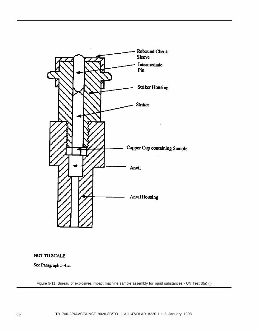
Figure 5-11. Bureau of explosives impact machine sample assembly for liquid substances - UN Test 3(a) (i)
36 TB 700-2/NAVSEAINST 8020-8B/TO 11A-1-47/DLAR 8220.1 • 5 January 1998
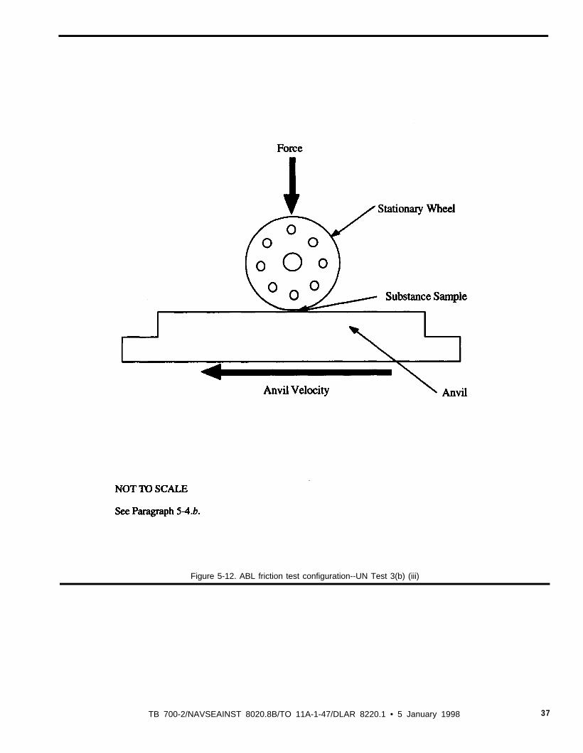
Figure 5-12. ABL friction test configuration--UN Test 3(b) (iii)
TB 700-2/NAVSEAINST 8020.8B/TO 11A-1-47/DLAR 8220.1 • 5 January 1998 37

Figure 5-13. Termal stability test configuration--UN Test 3(c)
38 TB 700-2/NAVSEAINST 8020-8B/TO 11A-1-47/DLAR 8220.1 • 5 January 1995
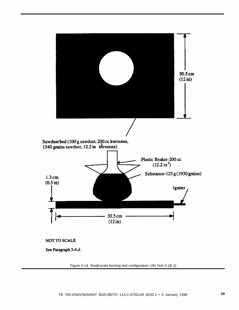
Figure 5-14. Small-scale burning test configuration--UN Test 3 (d) (i)
TB 700-2/NAVSEAINST 8020.8B/TO 11A-1-47/DLAR 8220.1 • 5 January 1998 39
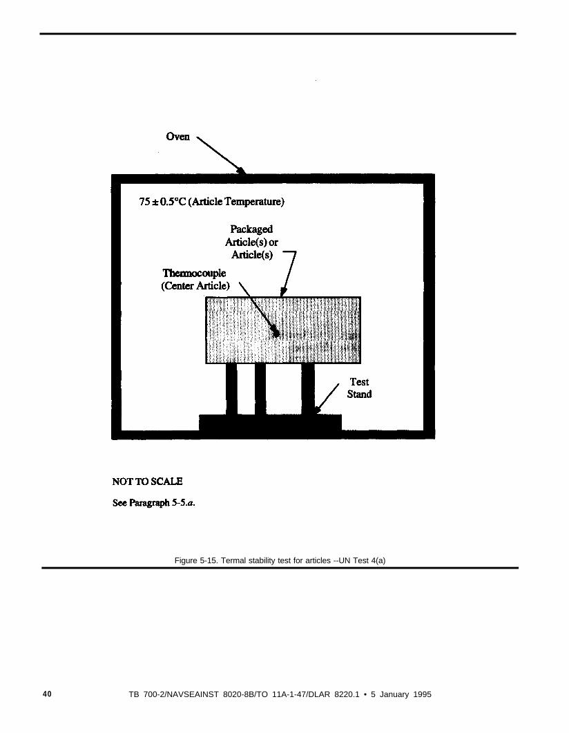
Figure 5-15. Termal stability test for articles --UN Test 4(a)
40 TB 700-2/NAVSEAINST 8020-8B/TO 11A-1-47/DLAR 8220.1 • 5 January 1995
Figure 5-16. Steel tube drop test for liquids--UN Test 4(b) (i)
TB 700-2/NAVSEAINST 8020.8B/TO 11A-1-47/DLAR 8220.1 • 5 January 1998 41
Figure 5-17. Twelve meter drop test configuration--UN Test 4(b) (ii)
42 TB 700-2/NAVSEAINST 8020.8B/TO 11A-1-47/DLAR 8220.1 • 5 January 1998
Figure 5-4
Figure 5-18. Cap sensitivity test configuration--UN Tests 5(a) and 7(a)
TB 700-2/NAVSEAINST 8020.8b/TO 11A-1-47/DLAR 8220.1 • 5 January 1998 43
Figure 5-4
Figure 5-19. Alternate cap sensitivity test configuration--UN Tests 5(a) and 7(a)
44 TB 700-2/NAVSEAINST 8020.8B/TO 11A-1-47/DLAR 8220.1 • 5 January 1998
NOT TO SCALE
8ASME B16.11-1991, “‘Forged Fittings, Socket-Welding and Threaded,” American Society ofMechanical Engineers, New York, NY (latest version).
See Paragraph 5-6.b.
Figure 5-20. Daflagration to detonation teat configuration—UN Test 4(b) (II)
TB 700-2/NAVSEAINST 8020.8B/TO 11A-1-47/DLAR 8220.1 • 5 January 1998 45

NOT TO SCALE
See Paragraph 5-6. c.
Figure 5-21. Typical wood fuel arrangement for external fire test for Harzard Division 1.5—UN Test 5(c)
46 TB 700-2/NAVSEAINST 8020.8BTO 11A-1-471DLAR 8220.1 • 5 January 1998
NOT TO SCALE
See Paragraph 5-6. d.
Figure 5-22. Prince incendiary spark test arrangement—UN Test S(d)
TB 700-2/NAVSEAINST 8020.8B/TO 11A-147/DLAR 8220.1 • 5 January 1998 47
NOT TO SCALE
See Paragraph 5-7.a.
Figure 5-23. Single package test arrangement-UN Test 6(a)
48 TB 700-2/NAVSEAINST 8020.8B/TO 11A-147/DLAR 8220.1 l 5 January 1998
Figure 5-24. Typical stacks test arrangement-UN Test 6(b)
C R O S S - S E C T I O N A L V I E W
NOT TO SCALE
See Paragraph 5-7.b.
TB 700-2/NAVSEAINST 8020.8B/TO 11A-147/DLAR 8220.1 • 5 January. 1998 49
See Paragraph 5-7.c.
Figure 5-25. Typical wood fuel arrangement for external (bonfire) test-UN Test b(c)
50 TB 700-2/NAVSEAINST 8020.8B/TO 11A-1-47/DLAR 8220.1 • 5 January 1998
See Paragraph 5-8 .b.
Figure 5-26. gap test configuration UN Test 7(b)
TB 700-2/NAVSEAINST 8020.8B/TO 11 A-147/DLAR 8220.1 • 5 January 1998 51
TARGET PLATE (6.4 cm (0.25 in)
See Paragraph 5-8.c.
Figure 5-27. Susan imports test arrangement-UN Tom 7(c) (l)
52 TB 700-2/NAVSEAINST 8020.8BTO 11 A-147/DLAR 8220.1 • 5 January 1998
NOT TO SCALE
See Paragraph 5-8.c.
Figure 5-28. Susan projectile-UN Test 7(c) (l)
TB 700-2/NAVSEAINST 8020.8B/TO 11A-1-47-DLAR 8220.1 • 5 January 1998 53
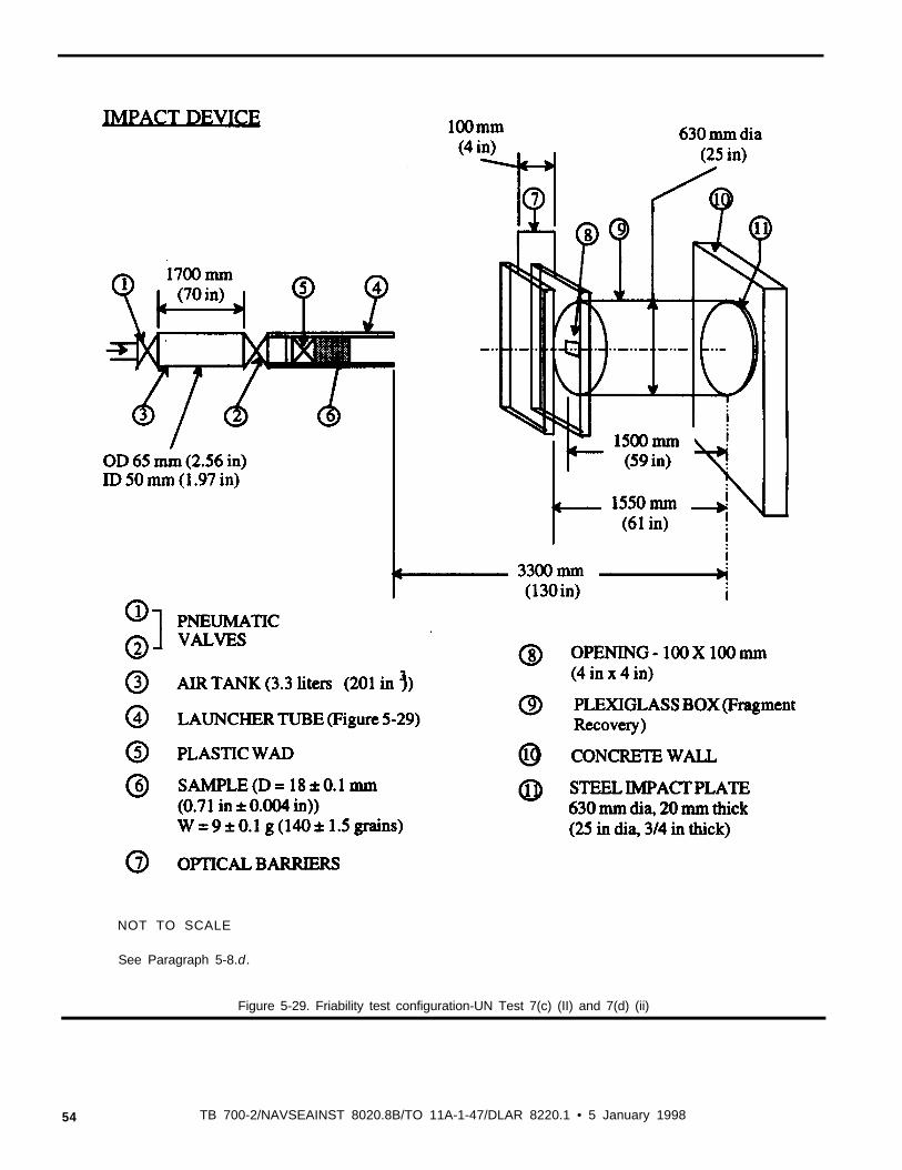
NOT TO SCALE
See Paragraph 5-8.d.
Figure 5-29. Friability test configuration-UN Test 7(c) (II) and 7(d) (ii)
54 TB 700-2/NAVSEAINST 8020.8B/TO 11A-1-47/DLAR 8220.1 • 5 January 1998
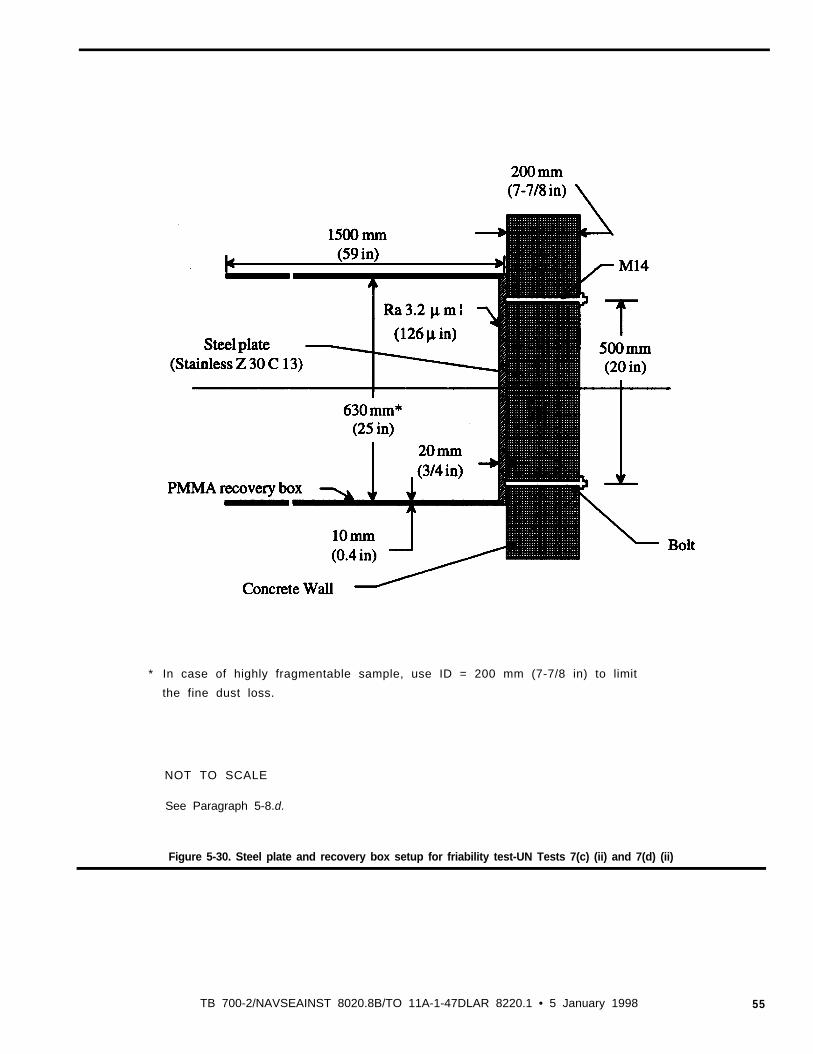
* In case of highly fragmentable sample, use ID = 200 mm (7-7/8 in) to limit
the fine dust loss.
NOT TO SCALE
See Paragraph 5-8.d.
Figure 5-30. Steel plate and recovery box setup for friability test-UN Tests 7(c) (ii) and 7(d) (ii)
TB 700-2/NAVSEAINST 8020.8B/TO 11A-1-47DLAR 8220.1 • 5 January 1998 55
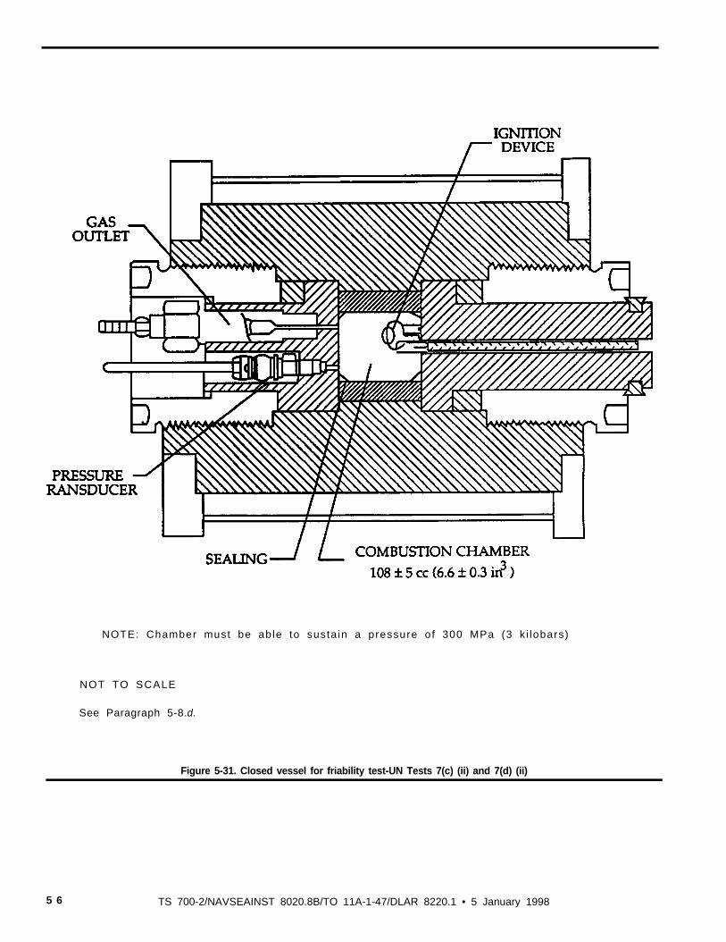
NOTE: Chamber must be able to susta in a pressure of 300 MPa (3 k i lobars)
NOT TO SCALE
See Paragraph 5-8.d.
Figure 5-31. Closed vessel for friability test-UN Tests 7(c) (ii) and 7(d) (ii)
5 6 TS 700-2/NAVSEAINST 8020.8B/TO 11A-1-47/DLAR 8220.1 • 5 January 1998
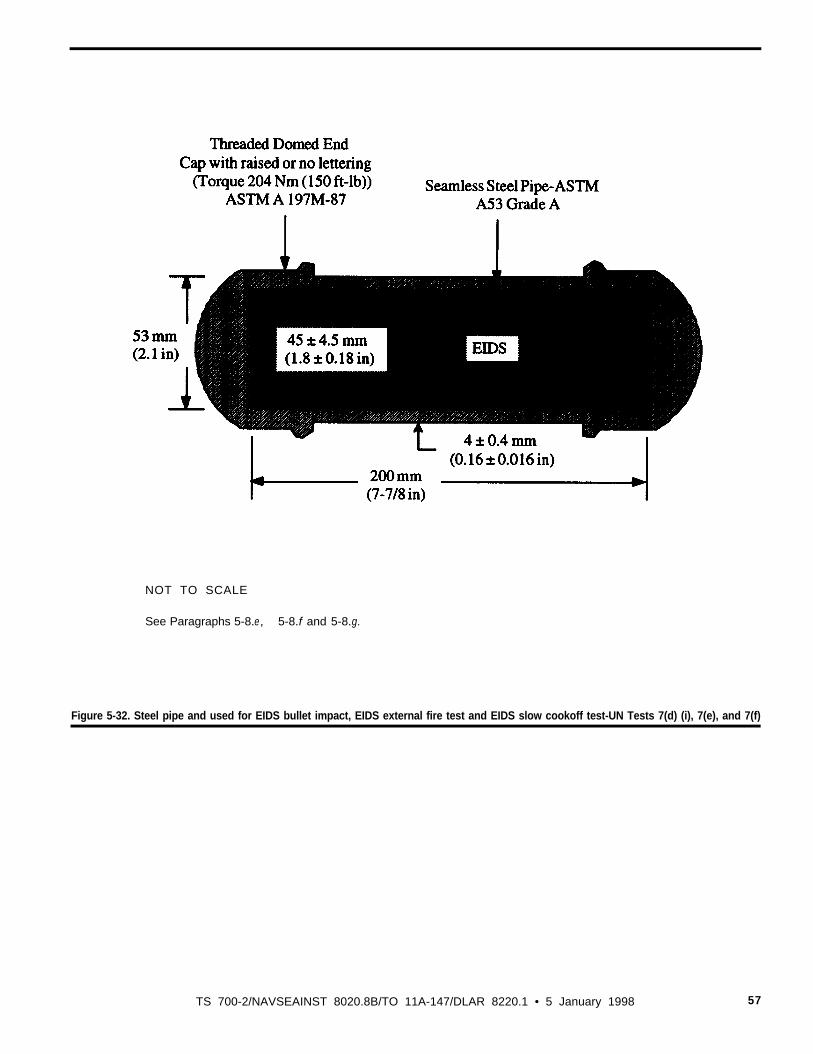
NOT TO SCALE
See Paragraphs 5-8.e, 5-8.f and 5-8.g.
Figure 5-32. Steel pipe and used for EIDS bullet impact, EIDS external fire test and EIDS slow cookoff test-UN Tests 7(d) (i), 7(e), and 7(f)
TS 700-2/NAVSEAINST 8020.8B/TO 11A-147/DLAR 8220.1 • 5 January 1998 57
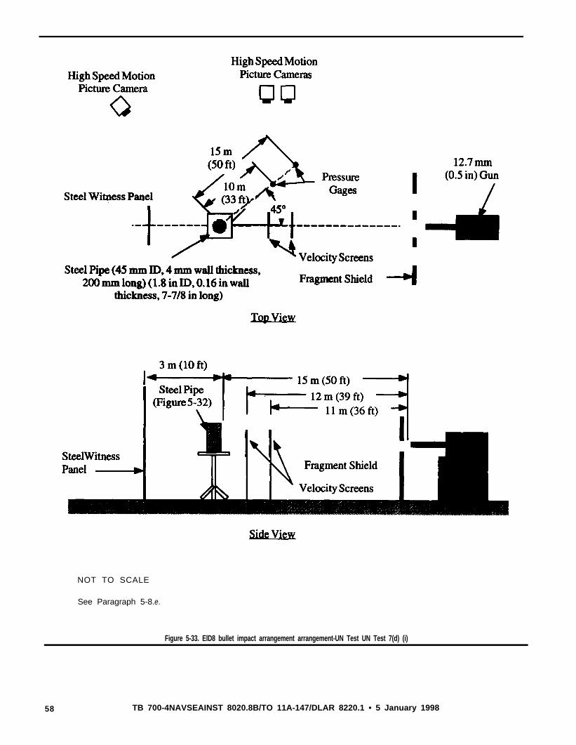
NOT TO SCALE
See Paragraph 5-8.e.
Figure 5-33. ElD8 bullet impact arrangement arrangement-UN Test UN Test 7(d) (i)
58 TB 700-4NAVSEAINST 8020.8B/TO 11A-147/DLAR 8220.1 • 5 January 1998
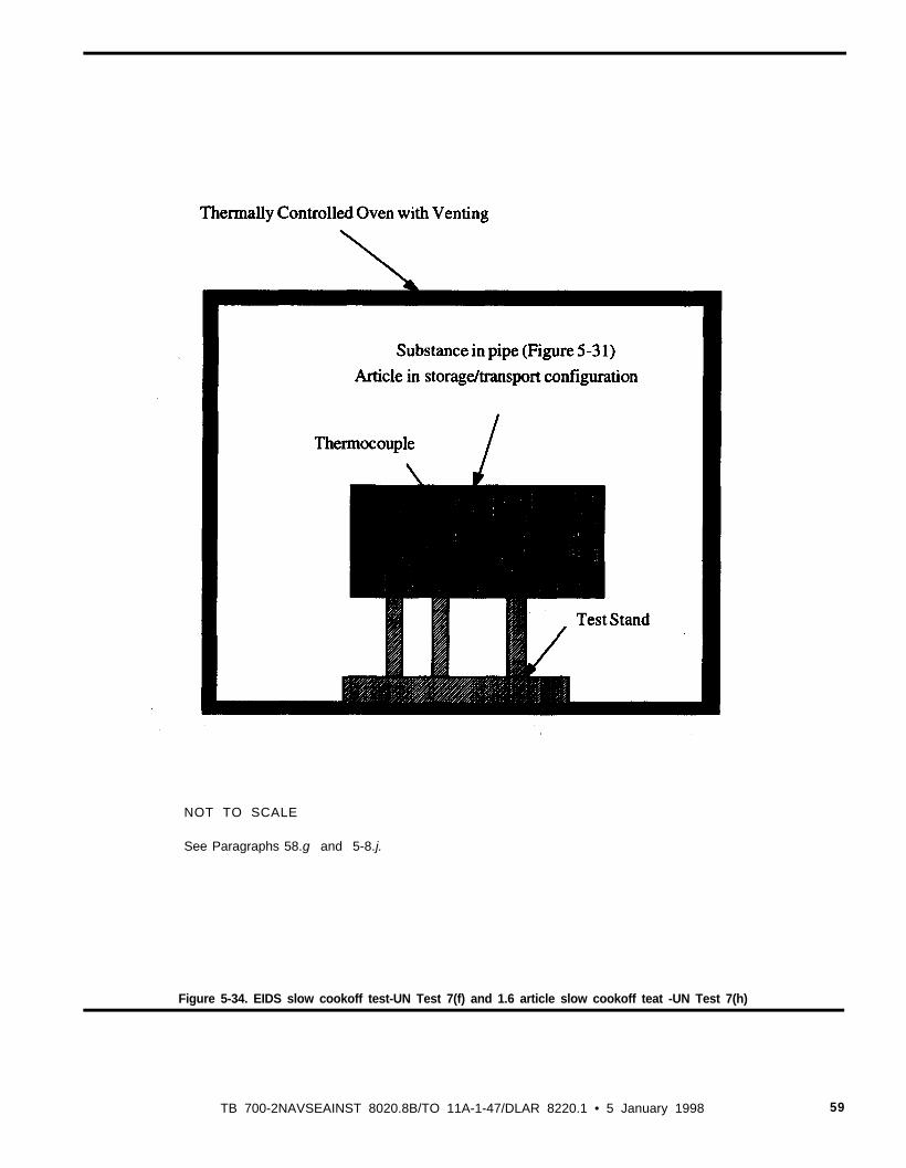
NOT TO SCALE
See Paragraphs 58.g and 5-8.j.
Figure 5-34. EIDS slow cookoff test-UN Test 7(f) and 1.6 article slow cookoff teat -UN Test 7(h)
TB 700-2NAVSEAINST 8020.8B/TO 11A-1-47/DLAR 8220.1 • 5 January 1998 59
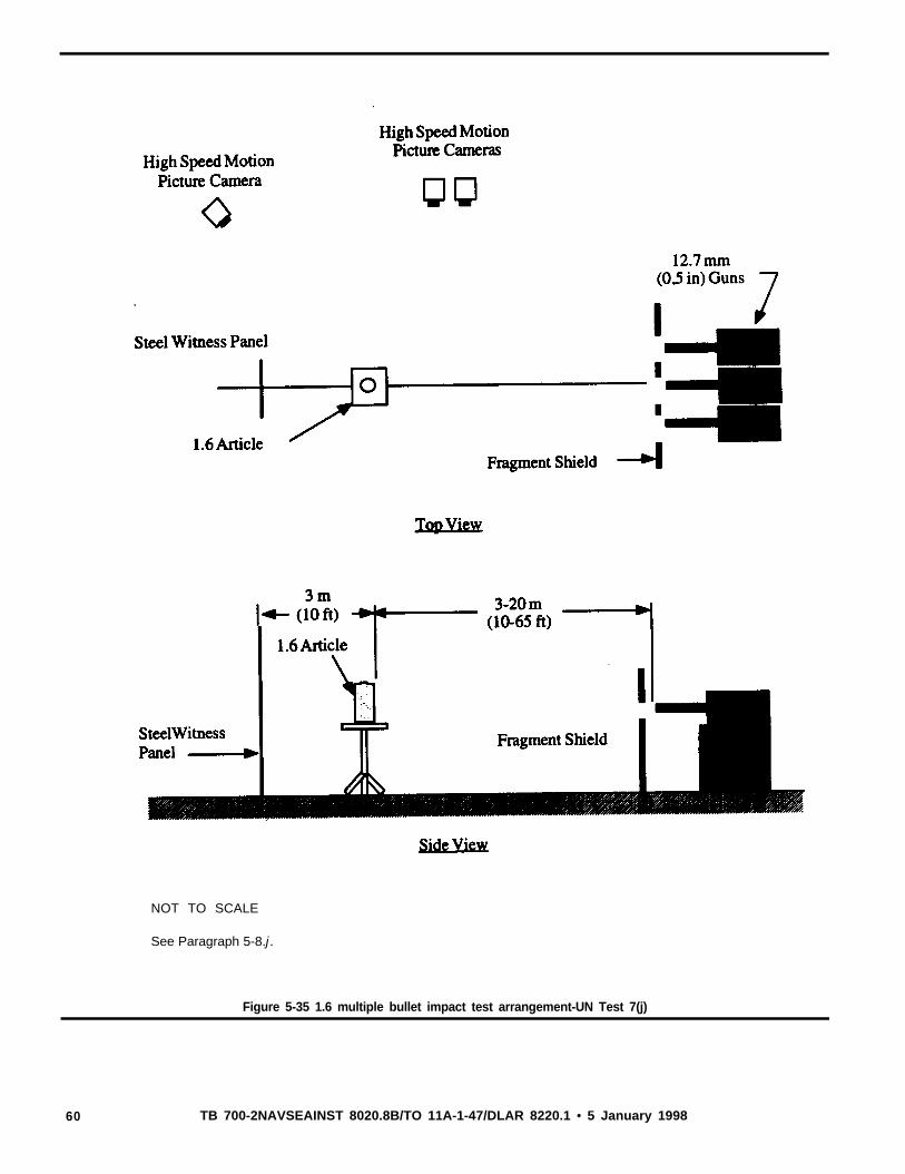
NOT TO SCALE
See Paragraph 5-8.j .
Figure 5-35 1.6 multiple bullet impact test arrangement-UN Test 7(j)
60 TB 700-2NAVSEAINST 8020.8B/TO 11A-1-47/DLAR 8220.1 • 5 January 1998
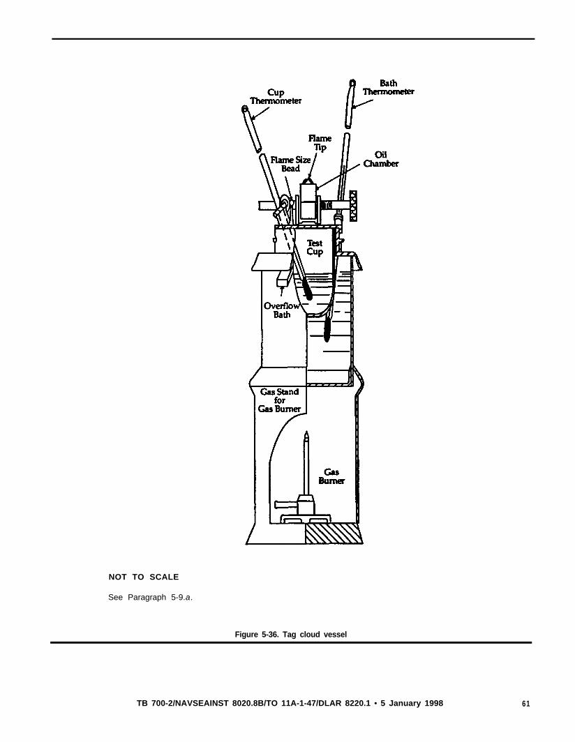
NOT TO SCALE
See Paragraph 5-9.a.
Figure 5-36. Tag cloud vessel
TB 700-2/NAVSEAINST 8020.8B/TO 11A-1-47/DLAR 8220.1 • 5 January 1998 61
C h a p t e r 6Instrumentation, interpretation of results anda l te rna te t es ts
6-1. IntroductionThis chapter specifies minimum requirements for instruments andequipment for measurement of airblast pressure, fragment dispersal,thermal flux. and firebrands associated with tests prescribed in chapter 5, and interpretation of the results in order to assign the properhazard division. Minimum requirements for data analysis and report-ing are also specified. In addition, acceptable alternate test proce-dures are presented.
a. Blast pressure measurements are to be used for the determina-tion of a net explosive weight for quantity distance (NEWQD) (seeparas 4-9d and 6-2) of configurations of reactive materials in am-munition as they are packaged and stored. or of ammunition constit-uents whose contribution to the total energy release in a single eventis not known. For example, Hazard Division 1.3 material in assem-bled ammunition may contribute to the overall explosive yield.
b. Observations of fragment dispersal, areal density (see para6-3b). and individual weights are necessary for the determination ofminimum separation distances consistent with established criteria forfragment hazards to personnel.
c. Measurements of the thermal radiation field (thermal flux) andobservations of firebrands are used to determine the maximum sepa-ration distance for Hazard Divisions 1.3 and 1.4 materials consistentwith established criteria for thermal hazards for personnel and fuepropagation by firebrands.
d. Alternate test procedures that are acceptable to the DOD Haz-ard Classifiers are presented at the end of this chapter. These alter-nate tests for purposes of hazard classification are taken frommodified Tri-Service test protocols for qualification and weaponssystems safety.
6-2. Blast measurementsc. Blast parameters.(1) Blast output is to be evaluated with reference to the classical
explosive blast ‘waveform illustrated in Figure 6-1. Parameters de-fining the waveform and indicated in the figure include-
(a) Peak or maximum over-pressure that occurs at the instant ofpulse arrival in the classical waveform.
(b) Positive phase duration, or the interval between shock arrivaland the time, at which the overpressure returns to zero.
(c) Positive phase impulse defined as the integral of the overpres-sure from the time of shock arrival to the end of the positive phase.
(2) The pressure and impulse are used to compute values ofNEWOD to represent the amount of material under consideration.
b. Data acquisition system. A system for measuring and record-ing blast over-pressure as a function of time consists of a transducer.signal conditioning equipment appropriate to the transducer type,and recording and reproduction &vices. The transducer may be anyone of a variety of electromechanical or electronic types having afrequency response adequate to resolve the blast pressure pulse. Forpurposes of NEWQD determination, for items whose net explosiveweights are below 1000 kg, the basic data acquisition system shouldhave a system frequency response of at least 0.01 Hz-20 kHz (seeApp A, Ref 10).
c. Transducer deployment and calibration. For any test that isexpected to produce an overpressure pulse, pressure transducers willbe positioned so as to detect the free-field overpressure at distanceswhere it is expected to attain the levels 70, 35, 7, and 3.5 kPa (10.5, 1, 0.5 psi) based on a pre-test estimate of the yield. Two lines oftransducers will be employed. These will be positioned at least 90°apart. If the test item has a line of symmetry, one line of transducersshould be placed along this line.
(1) The gauges will be mounted flush with the ground surface or,alternatively, in above-ground fixtures designed to minimize ob-struction of the flow, with the sensing face of each gauge parallel tothe direction of flow.
(2) The gauges will have been calibrated prior to the tests, and
the testing activity is responsible for continually maintaining up-to-date dynamic calibration data for gauges, utilizing laboratory proce-dures appropriate to the transducer type.
(3) An electronic calibration pulse of amplitude simulating thatof the anticipated peak pressure will be recorded immediately beforeeach test.
d. Data analysis. Pressure-time records will be analyzed to deter-mine peak pressures and positive phase impulses.
(1) The barometric pressure, ambient air temperature, and windvelocity and direction at the time of the test will be recorded andreported. These values will be used to convert the measured dis-tances, times, pressures, and impulses to Standard or Sea LevelConditions (atmospheric pressure of 101.36 kPa (14.7 psi), atmos-pheric temperature of 288.16° K (15°C).
(2) The following equations will be used to make the conversion:(a) PSL = PTS x FP(b) RSL = PTS x FR
(c) TSL = TTS x FT(d) TSL = ITS x FI
where P is pressure, R is distance, T is time, I is impulse; thesubscript SL and TS refer to sea level or standard conditions and tomeasurements made at the test site, respectively.
(3) The four factors Fp, FR, FT, and FIare defined as follows:(a) FP = (PSI/PTS)(f) FR = (PTS/PSL)
1/3
(c) FT = (PTS/PSL)1/3 x (TSL/TTS)1/2
(d) FI = (PSL/PTS)- x (TSL/TTS)1/2
where P is barometric pressure and T is absolute atmospheric tem-perature. As defined above PSLis 101.36 kPa (14.7 psi) and TSLis288.16° K (15°C).
(4) Two sets of blast measurements should be reported-thosetaken at the test site and the test site measurements converted tostandard conditions.
e. Data interpretation. Any observed anomalies in the recordeddata that cannot be attributed simply to instrument malfunction willbe noted. In the event that a systematic, substantial difference of thewaveform from the classical shape in Figure 6-1 is observed, suchas the absence of an initial peak, the peak pressure calculations forNEWQD described below may be. dispensed with in favor of apresentation of the records themselves together with an analysis. Ifno anomalies are observed, the pressure-distance and impulse-dis-tance data which have been converted to standard conditions will beanalyzed to determine NEWQD (this procedure is described below).These values of NEWQD will be reported. Reports of tests ofcomplete rounds of ammunition which result in the assignment toHazard Division 1.1 will include data on equivalence of includedHazard Division 1.3 components such as propelling charges.
f. Effective explosive weight (EEW). The EEW of a particularexplosive, device, event, stack, etc., is the weight of TNT (hemi-spherical TNT surface burst, Fig 6-2) required to produce a selectedshockwave parameter of equal magnitude to that produced by a unitweight of the material under test. A given material will have severalEEW’s depending on the shockwave parameter selected.
(1) Expressed as a ratio of the weight of the material under testto that of TNT in Figure 6-2, the EEW of an explosive morepowerful than TNT is greater than unity; the EEW of one lesspowerful is less than unity. Under this definition, the values of EEWdetermined respectively on the basis of the pressure and the impulsemeasured at a given location may differ, and both will be functionsof distance, geometry, or donor configuration.
(2) Hence, the general concept of EEW has significance only ifthe observed waveform is generally similar to the classical formshown in Figure 6-1 and if the geometry of the test material issimilar to that of the TNT standard in Figure 6-2. For strictlyhazard classification purposes, the EEW of a material is the weightof a bare TNT hemisphere on flat ground (App A, Ref 11) thatproduces the same free-field overpressure or impulse at a givendistance from the test article.
(3) Peak overpressure and scaled positive phase impulse (impulse(I) divided by the cube root of charge weight (W)) for a bare TNThemisphere are given in Figure 6-2 as a function of the scaled
62 TB 700-2/NAVSEAINST 8020.8B/TO 11A-1-47/DLAR 8220.1 • 5 January 1998
range-the actual distance (R) from the charge center, divided bythe cube root of charge weight (W). Table 6-1 presents the equa-tions which were used to generate these curves. NOTE: These equa-tions are simplifications of those appearing in the Kingery andBulmash reference (App A, Ref 11). They are accurate to within0.2% of the full Kingery equations.
(4) EEW based on peak pressure is defined as follows:EEW (pressure) = (Rarticle/Rstandard)
3 p = constant
that is. for each pressure level of interest, the EEW (pressure) is thecube of the ratio of the distances (article and standard) at which thatpressure occurs.
(5) EEW based on impulse is defined as follows: Since bothimpulse and distance are scaled according to the cube root of theexplosive weight, finding the point on the standard impulse-distancecurve corresponding to a measured value from the test data meansfinding the intersection of a line of slope one (on a log-log plot)passing through the test data and intersecting the standard curve.Either the cube of the ratio of the impulse for the intersection pointwith that for the standard curve or the cube of the ratio of theground ranges provides the EEW (impulse) at that point.
EEw (impulse) = (Iarticle/Istandard) or (Rarticle/stadard)3
Note. Ratios taken along a line with slope of one on a log-log plot.
(6) As described above, both EEW’s are functions of scaledrange. The EEw’s should be reported in both graphical and tabularform as a function of the scaled range. In addition, an average EEWbased on each parameter should also be reported.
(7) The (EEW)MAX is the higher of the EEW’s determined forpeak overpressure and positive phase impulse, each averaged overthe range 70-3.5 kPa (10-0.5 psi) for the geometry of the donormunition.
(8) The NEWQD is the (EEW)MAX (see para 6-2f(7) above) forthe ammunition (including Hazard Division 1.1 and Hazard Division1.3 contributions) minus the (EEW)MAX for only the Hazard Divi-sion 1.1 component of the ammunition, and then added to the HEW(see para 4-90) for the ammunition.
(9) Sometimes, based on physical evidence, it is possible to reachthe conclusion that division 1.3 material did not contribute to thedetonation reaction of division 1.1 material in an ammunition item.For example, a high explosive warhead detonation might project therocket motor a short distance away where the propellant grain sub-sequently burns out. If the rocket motor case is substantially intact,showing no evidence of an internal detonation-type reaction, theNEWQD may be set equal to the high explosive weight (HEW) ofthe warhead. Similarly, recovery of all or a substantial portion of anunreacted rocket motor grain or propelling charge may establishnon-contribution. For this reason, it may be prudent to conducttesting of an all-up-round or cartridge before testing the high explo-sive component alone.
6-3. Fragment hazard assessmenta. Introduction. The evaluation of fragment hazard effects is con-
ducted as an adjunct to the Single Package (6(a)), Stack Test (6(b))and/or the External Fire Test (6(c)). Two methods can be used:
(1) Near field fragment sampling using collection media and ve-locity measurement or
(2) Fragment collection from the ground plane. The selection ofthe appropriate method depends on the article being evaluated (Hax-ard Division 1.1 or 1.2) and the resources and expertise of thetesting activity.Note. Note that the “Method 1” approach described in UK previous edition ofthis publication (dated Dec ‘89), and the analytical procedures based on thatmethod, remains valid and may be used for hazardous fragment distancedeterminations in lieu of the Method 1 described below.
b. Hazardous fragment. Under currently applicable explosivessafety standards, a fragment hazardous to personnel in the open isdefined as one whose kinetic energy at impact exceeds 79 J (58 ft-
lb). An areal density of such fragments not exceeding one per 55.7m2 (600 ft2) is considered acceptable.
c. Firebrands. The probability of a hit is dependent on fragmentdensity in the same way as other fragments. However, injury ordamage may result from the thermal and chemical energy content ofthe firebrand as well.
d. Fragment field sampling. Fragment field sampling will be ac-complished using one of two methods. based on the results of singlepackage testing.
(1) Method 1 for fragment field sampling-Single package testindicates there is a risk of mass detonation (Hazard Division 1.1classification expected).
(a) This method is generally used for Hazard Division 1.1. arti-cles and requires the characterization of the fragment distribution(mass, number. shape and velocity) resulting from the initiation of asingle package of articles. Custom designed and constructed frag-mentation arenas are used to measure these parameters. Typicalconstruction utilizes steel plates and high speed motion picturecameras to measure fragment velocity and fiberboard collection ma-terial to capture fragments. Velocity measurement and fragmentcollection are accomplished as a function of ejection zone measuredaround the vertical axis of the package. The mass, presented areaand velocity data for all fragments weighing more than 20 g (310grains) are used as input to a simulation model FRAGHAZ (App A.Ref 12) which computes the Q-D requirements using a Monte Carlosimulation routine.
(b) It has been demonstrated that packages of Hazard Division1.1 articles may form high density, enhanced velocity (as comparedto single units) concentrations of fragments when detonated. Thesefragment concentrations result from the collision and interaction offragments from adjacent articles in the package. They will producethe highest safety concern and must be characterized. It is recom-mended that a 360° steel plate arena similar to the one illustrated inFigure 6-3 be used to determine the position of interaction areas forthe package being evaluated. The center of the package should bepositioned at the geometric center of the arena. The height of thepackage should also be centered on the steel plates. The distancefrom the steel plates to the package is determined by-
Rp= 2*EEW1/3
andwhere Rp= distance between the package and steel plates (m)
EEW = effective explosive weight (kg)
The outside surface of the witness plates should be marked in tendegree azimuthal zones using-
= 2 1c Rp/36where 8 = width of ten degree zone (m)
A single article within the package should be initiated. Determina-tion of the unit which will produce the most hazardous fragmenta-tion effects may require several tests for a package which containsmore than one non-symmetrical detonation source. The velocity ofthe fragments should be measured using high-speed motion picturecameras positioned to observe the outside surface of the witnessplates. The average velocity of each fragment striking the witnesspanel is determined by dividing the distance to the plate by the timeof flight of the fragment.
(c) The design of the Fragment Collection arena is based uponthe position of the fragment interaction areas measured by the Den-sity/Velocity arena. The azimuthal zone containing the most dense,highest velocity fragments should be characterized using bundles offiberboard panels. Each panel is 12.7 mm (0.5 in) thick, 1.2 m (4 ft)wide by 2.4 m (8 ft) tall. Nintey six panels are banded together toform a bundle. The collection bundles are positioned at a distancewhich will prevent severe blast damage using-
Rc = 4*EEW1/3
where Rc = distance to the recovery bundles (m)
TB 700-2/NAVSEAINST 8020.8B/TO 11A-147/DLAR 8220.1 • 5 January 1998 63
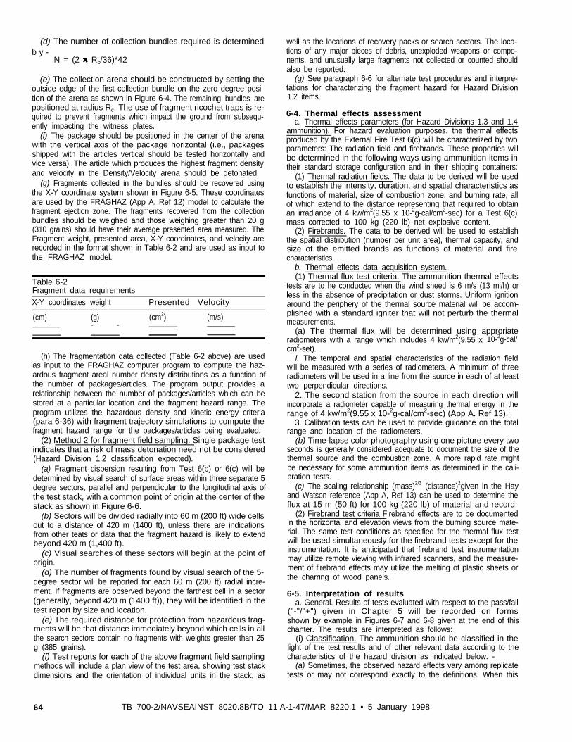
(d) The number of collection bundles required is determinedb y -
N = (2 IC Rc/36)*42
(e) The collection arena should be constructed by setting theoutside edge of the first collection bundle on the zero degree posi-tion of the arena as shown in Figure 6-4. The remaining bundles arepositioned at radius Rc. The use of fragment ricochet traps is re-quired to prevent fragments which impact the ground from subsequ-ently impacting the witness plates.
(f) The package should be positioned in the center of the arenawith the vertical axis of the package horizontal (i.e., packagesshipped with the articles vertical should be tested horizontally andvice versa). The article which produces the highest fragment densityand velocity in the Density/Velocity arena should be detonated.
(g) Fragments collected in the bundles should be recovered usingthe X-Y coordinate system shown in Figure 6-5. These coordinatesare used by the FRAGHAZ (App A. Ref 12) model to calculate thefragment ejection zone. The fragments recovered from the collectionbundles should be weighed and those weighing greater than 20 g(310 grains) should have their average presented area measured. TheFragment weight, presented area, X-Y coordinates, and velocity arerecorded in the format shown in Table 6-2 and are used as input tothe FRAGHAZ model.
Table 6-2Fragment data requirementsX-Y coordinates weight Presented Velocity
(cm) (g) (cm2) (m/s)- -
(h) The fragmentation data collected (Table 6-2 above) are usedas input to the FRAGHAZ computer program to compute the haz-ardous fragment areal number density distributions as a function ofthe number of packages/articles. The program output provides arelationship between the number of packages/articles which can bestored at a particular location and the fragment hazard range. Theprogram utilizes the hazardous density and kinetic energy criteria(para 6-36) with fragment trajectory simulations to compute thefragment hazard range for the packages/articles being evaluated.
(2) Method 2 for fragment field sampling. Single package testindicates that a risk of mass detonation need not be considered(Hazard Division 1.2 classification expected).
(a) Fragment dispersion resulting from Test 6(b) or 6(c) will bedetermined by visual search of surface areas within three separate 5degree sectors, parallel and perpendicular to the longitudinal axis ofthe test stack, with a common point of origin at the center of thestack as shown in Figure 6-6.
(b) Sectors will be divided radially into 60 m (200 ft) wide cellsout to a distance of 420 m (1400 ft), unless there are indicationsfrom other teats or data that the fragment hazard is likely to extendbeyond 420 m (1,400 ft).
(c) Visual searches of these sectors will begin at the point oforigin.
(d) The number of fragments found by visual search of the 5-degree sector will be reported for each 60 m (200 ft) radial incre-ment. If fragments are observed beyond the farthest cell in a sector(generally, beyond 420 m (1400 ft)), they will be identified in thetest report by size and location.
(e) The required distance for protection from hazardous frag-ments will be that distance immediately beyond which cells in allthe search sectors contain no fragments with weights greater than 25g (385 grains).
(f) Test reports for each of the above fragment field samplingmethods will include a plan view of the test area, showing test stackdimensions and the orientation of individual units in the stack, as
well as the locations of recovery packs or search sectors. The loca-tions of any major pieces of debris, unexploded weapons or compo-nents, and unusually large fragments not collected or counted shouldalso be reported.
(g) See paragraph 6-6 for alternate test procedures and interpre-tations for characterizing the fragment hazard for Hazard Division1.2 items.
6-4. Thermal effects assessmenta. Thermal effects parameters (for Hazard Divisions 1.3 and 1.4
ammunition). For hazard evaluation purposes, the thermal effectsproduced by the External Fire Test 6(c) will be characterized by twoparameters: The radiation field and firebrands. These properties willbe determined in the following ways using ammunition items intheir standard storage configuration and in their shipping containers:
(1) Thermal radiation fields. The data to be derived will be usedto establish the intensity, duration, and spatial characteristics asfunctions of material, size of combustion zone, and burning rate, allof which extend to the distance representing that required to obtainan irradiance of 4 kw/m2(9.55 x 10-2g-cal/cm2-sec) for a Test 6(c)mass corrected to 100 kg (220 lb) net explosive content.
(2) Firebrands. The data to be derived will be used to establishthe spatial distribution (number per unit area), thermal capacity, andsize of the emitted brands as functions of material and firecharacteristics.
b. Thermal effects data acquisition system.(1) Thermal flux test criteria. The ammunition thermal effects
tests are to he conducted when the wind sneed is 6 m/s (13 mi/h) orless in the absence of precipitation or dust storms. Uniform ignitionaround the periphery of the thermal source material will be accom-plished with a standard igniter that will not perturb the thermalmeasurements.
(a) The thermal flux will be determined using approriateradiometers with a range which includes 4 kw/m2(9.55 x 10-2g-cal/cm2-set).
l. The temporal and spatial characteristics of the radiation fieldwill be measured with a series of radiometers. A minimum of threeradiometers will be used in a line from the source in each of at leasttwo perpendicular directions.
2. The second station from the source in each direction willincorporate a radiometer capable of measuring thermal energy in therange of 4 kw/m2(9.55 x 10-2g-cal/cm2-sec) (App A. Ref 13).
3. Calibration tests can be used to provide guidance on the totalrange and location of the radiometers.
(b) Time-lapse color photography using one picture every twoseconds is generally considered adequate to document the size of thethermal source and the combustion zone. A more rapid rate mightbe necessary for some ammunition items as determined in the cali-bration tests.
(c) The scaling relationship (mass)2/3 (distance)2given in the Hayand Watson reference (App A, Ref 13) can be used to determine theflux at 15 m (50 ft) for 100 kg (220 lb) of material and record.
(2) Firebrand test criteria Firebrand effects are to be documentedin the horizontal and elevation views from the burning source mate-rial. The same test conditions as specified for the thermal flux testwill be used simultaneously for the firebrand tests except for theinstrumentation. It is anticipated that firebrand test instrumentationmay utilize remote viewing with infrared scanners, and the measure-ment of firebrand effects may utilize the melting of plastic sheets orthe charring of wood panels.
6-5. Interpretation of resultsa. General. Results of tests evaluated with respect to the pass/fall
("-"/"+") given in Chapter 5 will be recorded on formsshown by example in Figures 6-7 and 6-8 given at the end of thischanter. The results are interpreted as follows:
(i) Classification. The ammunition should be classified in thelight of the test results and of other relevant data according to thecharacteristics of the hazard division as indicated below. -
(a) Sometimes, the observed hazard effects vary among replicatetests or may not correspond exactly to the definitions. When this
64 TB 700-2/NAVSEAINST 8020.8B/TO 11 A-1-47/MAR 8220.1 • 5 January 1998
OCCUIS, the DGDC should use its judgment or arrange for furthertesting.
(b) It is prudent to err on the side of caution, particularly in thecrucial decision as to whether or not a product is susceptible to massdetonation.
(c) Based on results obtained from the tests given in Chapter 5,the appropriate hazard division compatibility group can be assigned.Additionally, the appropriate UN Serial Number is determined byreferring to appropriate lists of UN Numbers (see para 4-8).
(2) Airblast effects. For articles that mass detonate (Hazard Divi-sion 1.1). the NEWQD (para 6-2(f)(8)) up to 100% of the actualweight of the active ingredients will be used. For protective con-struction design purposes, the explosive equivalence without limita-tion will be used. Note that the terms “detonation,” “explosion,” and“deflagration” which are used as reaction descriptors for test re-sponses that may be associated with airblast effects am defined inChapter 2.(3) Minimum hazardous fragment distance. Note that the mini-mum hazardous fragment distance (for one item) for Hazard Divi-sions 1.1. 1.2. and 1.3. as determined by testing, is specified in 100-ft units in parentheses preceding the hazard division designation; forexample, Hazard Division (12) 1.2 indicates that the minimum frag-ment distance is 1200 ft for this item. Also. specification of theminimum fragment distance is required for all Hazard Division 1.2items.
(a) For articles that mass detonate (Hazard Division 1.1), theminimum distance for personnel in the open (inhabited building) forfragment protection will be 381 m (1250 ft) unless another distanceis determined by teats. For operations in which variable numbers ofunits* are handle, a graduated distance is permitted when thearticle has been adequately evaluated to determine if the distance forthe minimum hazardous fragment density requirement as given inparagraph 6-36 and in DoD 6055.9-STD (App A, Ref 1) is lessthan 381m (1250 ft) for the number of units per operation. (See thereport on FRAGHAZ (App A, Ref 12) in the Method 1 discussiongiven in paragraph 63d(1)(a)). The results of the fragment analysiswill be noted in the test documentation.Note. *A unit is to be one article for unpackaged items such as bombs or oneouter package of articles for items such as fuzes. If an operation involvespalletized articles, then the unit shall be considered to be a pallet load.
(b) For articles that do not mass detonate but present a fragmenthazard (Hazard Division 1.2). the inhabited building distance isequated to the minimum hazardous fragment distance as determinedby Method 2 (para 6-3d(2)) or by alternate test methods given inparagraph 6-6b.
(4) Thermal effects. For items that present a mass or moderatefire hazard (Hazani Division 1.3 and 1.4, respectively), fivebrandthrow distances and thermal flux measurements are used to charac-terize the hazards and determine the hazard division.
(a) The firebrand throw distance for Hazard Division 1.4 may notexceed 15 m (50 ft); otherwise, the item is classified as HazardDivision 1.3.
(b) The irradiance for a burning Hazard Division 1.4 item maynot exceed that of the fire by more than 4 kw/m2(9.55 x 10-2g-cal/cm2-sec) at a distance of 15 m (50 ft) from the edge of the Test 6(c)stack for a mass corrected to 100 kg (220 lb) net explosive content(see para 5-7c(4)(c) 3) otherwise, the item is Hazard Division 1.3.
b. Summary of test criteria and method of assessing results. Therequirements summarized and referenced below are minimum forassignment of articles and materials into the appropriate hazarddivision. Teat Series 3 teats are used to determine if a substance isforbidden for transport. Test Series 4 tests are used to determine ifitems with substances that failed Test Series 3 tests or new articlesam forbidden for transport (see note for para 5-1b(3)(b)). TestSeries 6 tests are used to determine whether the item is classifiedHazard Division 1.1. 1.2. 1.3 or 1.4; Test Series 5 for HazardDivision 1.5; and Test Series 7 for Hazard Division 1.6. See para-graph entitled “Criteria and Method of Assessing Results" associatedwith each test in Chapter 5 for more details.
(1) Forbidden for transport.
(a) A substance is forbidden for transport if:1. The solid or liquid substance is considered impact sensitive
(see para 5-4u(4)) at a drop height of 10.16 cm (4.0 in) for solidsand 25.4 cm (10.0 in) for liquids in the Bureau of Explosives ImpactMachine Test 3(a)(i) (10 trials); and/or
2. The solid or liquid substance is considered friction sensitive ifany of the following results are obtained from the ABL FrictionTest 3(b) (iii)-visible sparks/flame, audible explosion, loud crack-ling noise, or detection of reaction products by a gas analyzer for afriction sensitiveness equal to or greater than dry PETN (see para5-4b4)); and/or
3. The solid or liquid substance is considered thermally unstablein the Thermal Stability Test at 75°C (Test 3(c)); that is, the sub-stance ignite-s or explodes, or the substance experiences self-heatingof 3°C or greater; andlor
4. The solid or liquid substance explodes or detonates in theSmall-Scale Burning Teat 3(d) (i).
(b) An article, packaged article, or a packaged substance is for-bidden for transport if:
l. The Thermal Stability Test for Articles and Packaged Articles(Test 4(a)) (does not apply to packaged substances) results in anexplosioh ignition, generation of colored fumes or odors, tempera-ture rise exceeding 3°C experienced, or the outside casing of thepackage or the outside packaging is damaged; and/or
2. The Steel Tube Drop Teat for Liquids (Test 4(b) (i)) results ina detonation for a drop of less than 5 m (197 in). If a local reactionoccurs for a drop less than 5 m (197 in) then transport in metalpackaging is prohibited unless suitability for transport can bedemonstrated.
3. The Twelve Meter Drop Test for Articles and Solid Sub-stances (Test 4(b) (ii)) (three drops with separate units) results in afire or explosion (rupture of the package is acceptable). (NOTE: Asubstance that fails Tests 3(a) (i), 3(b) (iii), or 3(d) (i) may be re-packaged to pass Teat 4(b) (ii) to allow transport; however, sub-stances that fail Test 3(c) are forbidden for transport regardless ofpackaging.)
(2) Hazard Division 1.1.(a) Explosion of total contents (see para 5-7a(4)) in the Single
Package Test 6(a) indicates a candidate for Hazard Division 1.1.(b) If the product is accepted as Hazard Division 1.1 and the
minimum hazardous fragment hazard distance does not exceed thedefault value of 381m (1250 ft) given in paragraph 6-5a(3)(a)above, then testing beyond the Single Package Test 6(a) or the StackTest 6(b) is not necessary.
(c) If the explosion of total contents (see para 5-7b(4)) appears tooccur almost instantaneously in either the Stack Test 6(b) or theExternal Fire (Bonfire) Test 6(c), then the item is assigned HazardDivision 1.1.
(3) Hazard Division 1.2. The item is assigned Hazard Division1.2 if an explosion reaction (see Glossary) results in one or more ofthe following events:
(a) Explosion of total contents (see para 5-7b(4)) does not occurin either the Stack Test 6(b) or the External Fire (Bonfire) Test 6(c);and/or (NOTE: If two or less acceptor packages detonate in a con-fined stack test with four acceptor packages or more, then thepackaged article can be hazard classified as Hazard Division 1.2;otherwise, it is hazard classified as Hazard Division 1.1.)
(b) Debris from the event perforates any of the three aluminumwitness plates in Teat 6(c); and/or
(c) More than 10 metallic projections, each with mass exceeding25 g (385 grains), are thrown more than 50 m (165 ft) from theedge of the Test 6(c) stack; and/or
(d) Any metallic projection with mass exceeding 150 g (2300grains) is thrown more than 15 m (50 ft) from the edge of the Test6(c) stack.
(4) Unit risk Hazard Division 1.2. For storage application a spe-cial category of Hazard Division 1.2. unit risk. has been designated(DoD 6055.9-STD. Chap 9, para C.2.a) (App A. Ref 1). The-mini-mum hazardous fragment distance for this category is determinedusing the areal number density criteria given in paragraph 6-36.
TB 700-2/4NAVSEAINST 8020.8B/TO 11A-1-47/DLAR 8220.1 • 5 January 1998 65
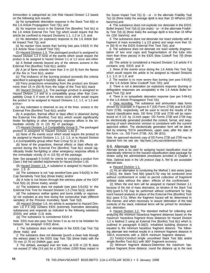
Ammunition is categorized as Unit Risk Hazard Division 1.2 basedon the following test results:
(a) No sympathetic detonation response in the Stack Test 6(b) orthe 1.6 Article Propagation Test 7(k); and
(b) No response occurs in the External Fire (Bonefire) Test 6(c) orthe 1.6 Article External Fire Test 7(g) which would require that thearticle be confined to Hazard Divisions 1.1, 1.2 or 1.3; and
(c) No detonation (or explosion) response in the 1.6 Article Bul-let Impact Test 7(j); and
(d) No reaction more severe than burning (see para 5-8i(4) in the1.6 Article Slow Cookoff Test 7(h).
(5) Hazard Division 1.3. The packaged product is assigned toHazard Division 1.3 if none of the events which would require theproduct to be assigned to hazard Division 1.1 or 1.2 occur and either
(a) A fireball extends beyond any of the witness screens in theExternal Fire (Bonfire) Test 6(c); and/or
(b) A jet of flame extends more than 3 m (10 ft) from the flamesof the fire in Test 6(c); and/or
(c) The imdiancc of the burning product exceeds the criteriaspecified in paragraph 6-5a(4)(b) above; and/or
(d) Fiery projections emanating from the product are thrownmore than 15 m (50 ft) from the edge of the Test 6(c) stack
(6) Hazard Division 1.4. The package product is assigned toHazard Division 1.4 and to a compatibility group other than Com-patibility Croup S if none of the events occur which would requirethe product to be assigned to Hazard Divisions 1.1, 1.2, or 1.3 andeither-
(a) Any indentation is observed on any of the three. screens in theExternal Fire (Bonfire) Teat 6(c); and/or
(b) A projection, thermal effect or blast effect is observed duringthe External Fire (Bonfire) Test 6(c) which would significantlyhinder fire-fighting or other emergency response efforts in the im-mediate vicinity (5 m (15 ft)) of package.
(7) Hazard Division 1.4 Compatibility Group S. The packagedproduct is assigned to Hazard Division 1.4s if-
(u) None of the events occur which would require the product tobe assigned to Hazard Divisions 1.1, 1.2, 1.3, or to Hazard Division1.4 (compatibility group other than Croup S) or 1.6N.
(b) None of the projections, thermal effects or blast effects ob-served during the External Fire (Bonfire) Teat 6(c) would sig-nificantly hinder fire-fighting or other emergency response efforts inthe immediate vicinity (5 m (15 ft)) of the package.Note. See paragraph 5-7c(4)(f) for criteria for excluding a product fromClass 1 that has satisfied requirements for Hazard Division 1.4S.
(8) Hazard Division 1.5. A substance is assigned to Hazard Divi-sion 1.5 if-
(a) The substance is not “cap sensitive”(see para 5-6a(4)) in theCap Sensitivity Test 5(a) (three trials); and/or
(b) A hole is not blown through the witness plate of the DDTTest 5(b) (ii) (three trials); and/or
(c) The substance does not explode (see para 5-6c(4)) in theExternal Fire Test for Hazard Division 1.5 (Test 5(c)); and/or
(d) The substance neither ignites and burns (mildly or vigorous-ly) nor explodes at any time during five consecutive trials (differentsamples) of the Princess Incendiary Spark Teat S(d).
(9) Hazard Division 1.6. An article is assigned to Hazard Divi-sion 1.6 if it only contains EIDS (extremely insensitive detonatingsubstances) and responds as indicated to the following substance(EIDS) and article (1.6) tests.
(a) The substance is considered EIDS if-Note. EIDS must also pass Test Series 3 so as not to be forbidden fortransport. See paragraph 6-5b(l) above.
1. The substance does not detonate in the EIDS Cap Test 7(a)(three trials); and
2. The substance does not detonate (punch a clean hole throughthe witness plate) in the EIDS Gap Test 7(b) (three trials) with the70 mm (2.76 in) EMMA gap; and
3. The airblast, averaged over ten trials, at 3.05 m (10 ft) doesnot exceed 27 kBa (3.9 psi) for a 333 m/lsec (1093 ft/sec impact in
the Susan Impact Teat 7(c) (i) - or - in the alternate Friability Teat7(c) (ii) (three trials) the average dp/dt is less than 15 MPa/ms (150bars/ms);and
4. The substance does not explode nor detonate in the EIDSBullet Impact Test 7(d) (i) (six trials) - or - in the alternate Friabil-ity Test 7(d) (ii) (three trials) the average dp/dt is less than 15 MPa/ms (150 bars/ms); and
5. The substance does not detonate nor react violently with afragment of mass exceeding 1 g (15 grains) and range more than 15m (50 ft) in the EIDS External Fire Test 7(e); and
6. The substsnce does not detonate nor react violently (fragmen-tation of two end caps and fragmentation of the tube intomom than three pieces) in the EIDS Slow Cookoff Test 7(f) (threetrials); and
(b) The article is considered a Hazard Division 1.6 article if itcontains only EIDS and if-
1. None of the events occur during the 1.6 Article Fire Test 7(g)which would require the article to he assigned to Hazard Divisions1.1. 1.2. or 1.3; and
2. The reaction is no more severe than burning (see para 5-8 i(4))in the 1.6 Article Slow Cookoff Test 7(h); and
3. There is not a detonation (or explosion) response (burning ordeflagration responses are acceptable) in the 1.6 Article Bullet Im-pact Test 7(j); and
4. There is no sympathetic detonation response (see pan 5-8k4))In the 1.6 Article Propagation Test 7(k).
c. Data recording, The substance and ammunition data formsshown by example in Figures 6-7 (DD Form 2738) and 6-8 (DDForm 2739). respectively, will be used to record the results of thehazard classification tests. DD firms 2738 and 2739 will be repro-duced on 8 1/2- by 11-inch paper. DD Forms 2738 and 2739 maybe electronically generated provided the content, format, and sequ-encing of each electronic version is consistent with the currentapproved edition. The electtonically generation form will be identi-fied by entering “EG”in parentheses, upper case, after the date ofthe form, i.e., DD Form 2738, JUL 96 (EG).Note. An approved electronic copy of DD Forms 2738 sad 2739 may beobtained from the web site: http://web.1.whs,osd.mil/diorhome.htm.
6-6. Alternate testAlternate tests to be used for assigning hazard classification must bespecitically referred in the hazard classification data package forreview using the administrative procedures provided in Chapter 3.Note. Optional tests in the UN protocol (App A, Ref 6) are acceptablealternate teats.
a. Hazard Division 1.1.(1) As an alternative to conducting the Method 1 test series (para
6-3d(1)), the Stack Test 6(b) (para-5-7b) may be conducted oncewithout confinement in order to permit collection of fragment/airblast data without the atten- effects of the confinement.
(2) When the end item will be assigned to Hazard Division 1.1because of the risk of mass detonation, an iteration of the Stack Test6(b) (pant 5-76) may be performed without confinement for frag-ment hazard analysis in place of the External Fire (Bonfire) Test6(c) (para 5-7c). When the fragment hazard will be determined inthis manner, and when necessary to assure detonation of the totalcontents of the stack, individual items will be primed for simultane-ous detonation.
b. Hazard Division 1.2. The standard method for collecting andanalyzing the minimum hazardous fragment distances based on themaximum hazardous fragment throw distances for Hazard Division1.2 is Method 2 using an External Fire (Bonfire) Test 6(c) which isoutlined in paragraph 6-3d(2). Inhabited building distance isequated to the minimum hazadous fragment distsnce. The follow-ing alternate test method results in a minimum fragment distance in100-A increments with a 200-ft minimum fragment distance.
(1) Test(s)-Conduct single unconfined Stack Test 6(b) and/orsingle Bonfire Test 6(c) with 360° fragment recovery.
(2) Minimum fragment distance-Determine the maximum has-ardous fragment throw distance, round the distance up to the next
66 TB 700-2/NAVSEAINST B020.8B/TO 11A-1-47/DLAR 8220.1 • 5 January 1998
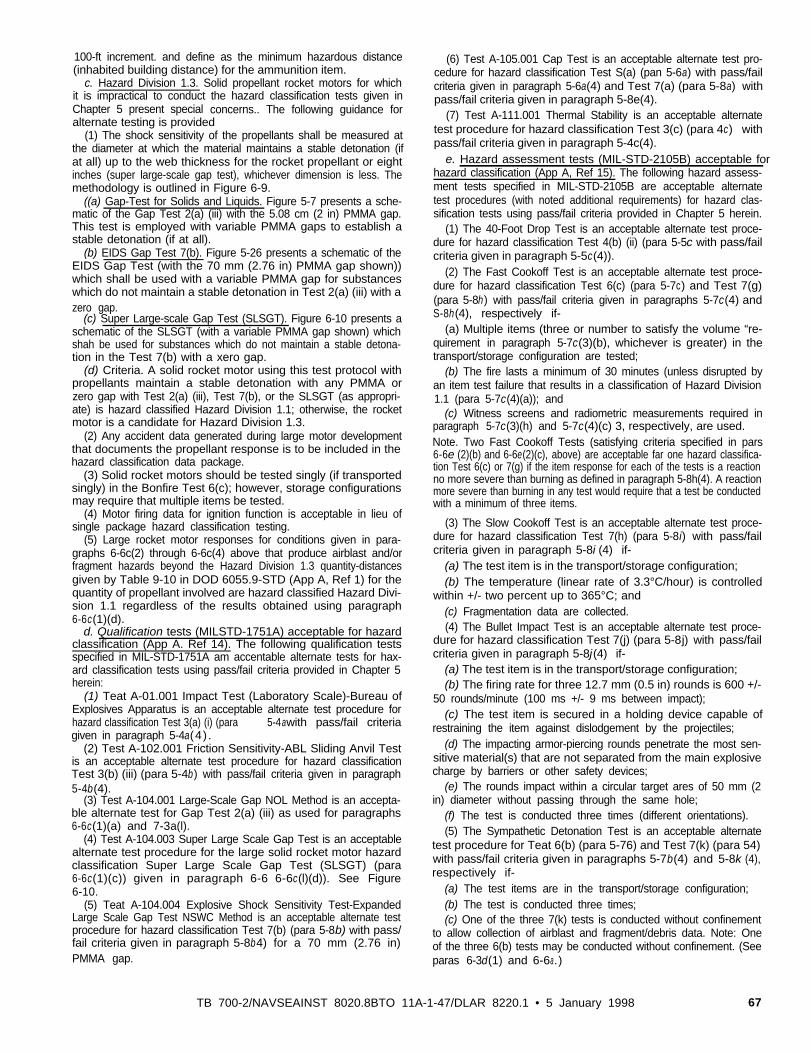
100-ft increment. and define as the minimum hazardous distance(inhabited building distance) for the ammunition item.
c. Hazard Division 1.3. Solid propellant rocket motors for whichit is impractical to conduct the hazard classification tests given inChapter 5 present special concerns.. The following guidance foralternate testing is provided
(1) The shock sensitivity of the propellants shall be measured atthe diameter at which the material maintains a stable detonation (ifat all) up to the web thickness for the rocket propellant or eightinches (super large-scale gap test), whichever dimension is less. Themethodology is outlined in Figure 6-9.
((a) Gap-Test for Solids and Liquids. Figure 5-7 presents a sche-matic of the Gap Test 2(a) (iii) with the 5.08 cm (2 in) PMMA gap.This test is employed with variable PMMA gaps to establish astable detonation (if at all).
(b) EIDS Gap Test 7(b). Figure 5-26 presents a schematic of theEIDS Gap Test (with the 70 mm (2.76 in) PMMA gap shown))which shall be used with a variable PMMA gap for substanceswhich do not maintain a stable detonation in Test 2(a) (iii) with azero gap.
(c) Super Large-scale Gap Test (SLSGT). Figure 6-10 presents aschematic of the SLSGT (with a variable PMMA gap shown) whichshah be used for substances which do not maintain a stable detona-tion in the Test 7(b) with a xero gap.
(d) Criteria. A solid rocket motor using this test protocol withpropellants maintain a stable detonation with any PMMA orzero gap with Test 2(a) (iii), Test 7(b), or the SLSGT (as appropri-ate) is hazard classified Hazard Division 1.1; otherwise, the rocketmotor is a candidate for Hazard Division 1.3.
(2) Any accident data generated during large motor developmentthat documents the propellant response is to be included in thehazard classification data package.
(3) Solid rocket motors should be tested singly (if transportedsingly) in the Bonfire Test 6(c); however, storage configurationsmay require that multiple items be tested.
(4) Motor firing data for ignition function is acceptable in lieu ofsingle package hazard classification testing.
(5) Large rocket motor responses for conditions given in para-graphs 6-6c(2) through 6-6c(4) above that produce airblast and/orfragment hazards beyond the Hazard Division 1.3 quantity-distancesgiven by Table 9-10 in DOD 6055.9-STD (App A, Ref 1) for thequantity of propellant involved are hazard classified Hazard Divi-sion 1.1 regardless of the results obtained using paragraph6-6c(1)(d).
d. Qualification tests (MILSTD-1751A) acceptable for hazardclassification (App A. Ref 14). The following qualification testsspecified in MIL-STD-1751A am accentable alternate tests for hax-ard classification tests using pass/fail criteria provided in Chapter 5herein:
(1) Teat A-01.001 Impact Test (Laboratory Scale)-Bureau ofExplosives Apparatus is an acceptable alternate test procedure forhazard classification Test 3(a) (i) (para 5-4awith pass/fail criteriagiven in paragraph 5-4a(4) .
(2) Test A-102.001 Friction Sensitivity-ABL Sliding Anvil Testis an acceptable alternate test procedure for hazard classificationTest 3(b) (iii) (para 5-4b) with pass/fail criteria given in paragraph5-4b(4).
(3) Test A-104.001 Large-Scale Gap NOL Method is an accepta-ble alternate test for Gap Test 2(a) (iii) as used for paragraphs6-6c(1)(a) and 7-3a(l).
(4) Test A-104.003 Super Large Scale Gap Test is an acceptablealternate test procedure for the large solid rocket motor hazardclassification Super Large Scale Gap Test (SLSGT) (para6-6c(1)(c)) given in paragraph 6-6 6-6c(l)(d)). See Figure6-10.
(5) Teat A-104.004 Explosive Shock Sensitivity Test-ExpandedLarge Scale Gap Test NSWC Method is an acceptable alternate testprocedure for hazard classification Test 7(b) (para 5-8b) with pass/fail criteria given in paragraph 5-8b4) for a 70 mm (2.76 in)PMMA gap.
(6) Test A-105.001 Cap Test is an acceptable alternate test pro-cedure for hazard classification Test S(a) (pan 5-6a) with pass/failcriteria given in paragraph 5-6a(4) and Test 7(a) (para 5-8a) withpass/fail criteria given in paragraph 5-8e(4).
(7) Test A-111.001 Thermal Stability is an acceptable alternatetest procedure for hazard classification Test 3(c) (para 4c) withpass/fail criteria given in paragraph 5-4c(4).
e. Hazard assessment tests (MIL-STD-2105B) acceptable forhazard classification (App A, Ref 15). The following hazard assess-ment tests specified in MIL-STD-2105B are acceptable alternatetest procedures (with noted additional requirements) for hazard clas-sification tests using pass/fail criteria provided in Chapter 5 herein.
(1) The 40-Foot Drop Test is an acceptable alternate test proce-dure for hazard classification Test 4(b) (ii) (para 5-5c with pass/failcriteria given in paragraph 5-5c(4)).
(2) The Fast Cookoff Test is an acceptable alternate test proce-dure for hazard classification Test 6(c) (para 5-7c) and Test 7(g)(para 5-8h) with pass/fail criteria given in paragraphs 5-7c(4) andS-8h(4), respectively if-
(a) Multiple items (three or number to satisfy the volume “re-quirement in paragraph 5-7c(3)(b), whichever is greater) in thetransport/storage configuration are tested;
(b) The fire lasts a minimum of 30 minutes (unless disrupted byan item test failure that results in a classification of Hazard Division1.1 (para 5-7c(4)(a)); and
(c) Witness screens and radiometric measurements required inparagraph 5-7c(3)(h) and 5-7c(4)(c) 3, respectively, are used.Note. Two Fast Cookoff Tests (satisfying criteria specified in pars6-6e (2)(b) and 6-6e(2)(c), above) are acceptable far one hazard classifica-tion Test 6(c) or 7(g) if the item response for each of the tests is a reactionno more severe than burning as defined in paragraph 5-8h(4). A reactionmore severe than burning in any test would require that a test be conductedwith a minimum of three items.
(3) The Slow Cookoff Test is an acceptable alternate test proce-dure for hazard classification Test 7(h) (para 5-8i) with pass/failcriteria given in paragraph 5-8i (4) if-
(a) The test item is in the transport/storage configuration;(b) The temperature (linear rate of 3.3°C/hour) is controlled
within +/- two percent up to 365°C; and(c) Fragmentation data are collected.(4) The Bullet Impact Test is an acceptable alternate test proce-
dure for hazard classification Test 7(j) (para 5-8j) with pass/failcriteria given in paragraph 5-8j(4) if-
(a) The test item is in the transport/storage configuration;(b) The firing rate for three 12.7 mm (0.5 in) rounds is 600 +/-
50 rounds/minute (100 ms +/- 9 ms between impact);(c) The test item is secured in a holding device capable of
restraining the item against dislodgement by the projectiles;(d) The impacting armor-piercing rounds penetrate the most sen-
sitive material(s) that are not separated from the main explosivecharge by barriers or other safety devices;
(e) The rounds impact within a circular target ares of 50 mm (2in) diameter without passing through the same hole;
(f) The test is conducted three times (different orientations).(5) The Sympathetic Detonation Test is an acceptable alternate
test procedure for Teat 6(b) (para 5-76) and Test 7(k) (para 54)with pass/fail criteria given in paragraphs 5-7b(4) and 5-8k (4),respectively if-
(a) The test items are in the transport/storage configuration;(b) The test is conducted three times;(c) One of the three 7(k) tests is conducted without confinement
to allow collection of airblast and fragment/debris data. Note: Oneof the three 6(b) tests may be conducted without confinement. (Seeparas 6-3d(1) and 6-6a.)
TB 700-2/NAVSEAINST 8020.8BTO 11A-1-47/DLAR 8220.1 • 5 January 1998 67
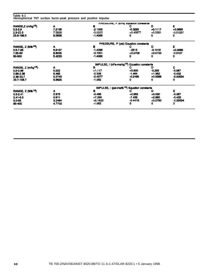
Table 6-1Hemispherical TNT surface burst--peak pressure and positive impulse
68 TB 700-2/NAVSEAINST 8020.8B/TO 11 A-1-47/DLAR 8220.1 • 5 January 1998
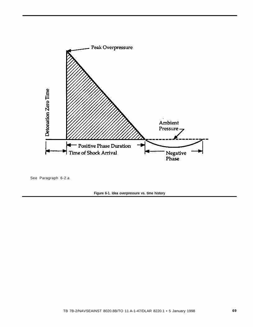
See Paragraph 6-2.a.
Figure 6-1. ldea overpressure vs. time history
TB 7B-2/NAVSEAINST 8020.8B/TO 11 A-1-47/DLAR 8220.1 • 5 January 1998 69
Figure 6-2. Hemispherical
See Paragraph 6-2.f(3).
70 TB 700-2NAVSEAINST 8020.8B/TO 11A-1-47/DLAR 8220.1 • S January 1998
Figure 6-3. Velocity
NOT TO SCALE
Notes: See Figure 6-4 for ricochet fence dimensions.See Paragraph 6-3.db)(b).
TB 7004NAVSEAINST 8020.8B/TO 11A-1-47/DLAR 8220.1 • 5 January 1998 71
Figure 6-4. Fragmentation
See Paragraph 6-3.d(l)(e).
72 TS 700-2/NAVSEAINST 8020.8B/TO 11A-1-47/DLAR 8220.1 January 1998
See Paragraph 6-3.d (1)(g).
Figure 6-5. Fragment collection coordinate system-method 1
TB 700-2/NAVSEAINST 8020.8B/TO 11A-1-47/DLAR 8220.1 • 5 January 1998 73
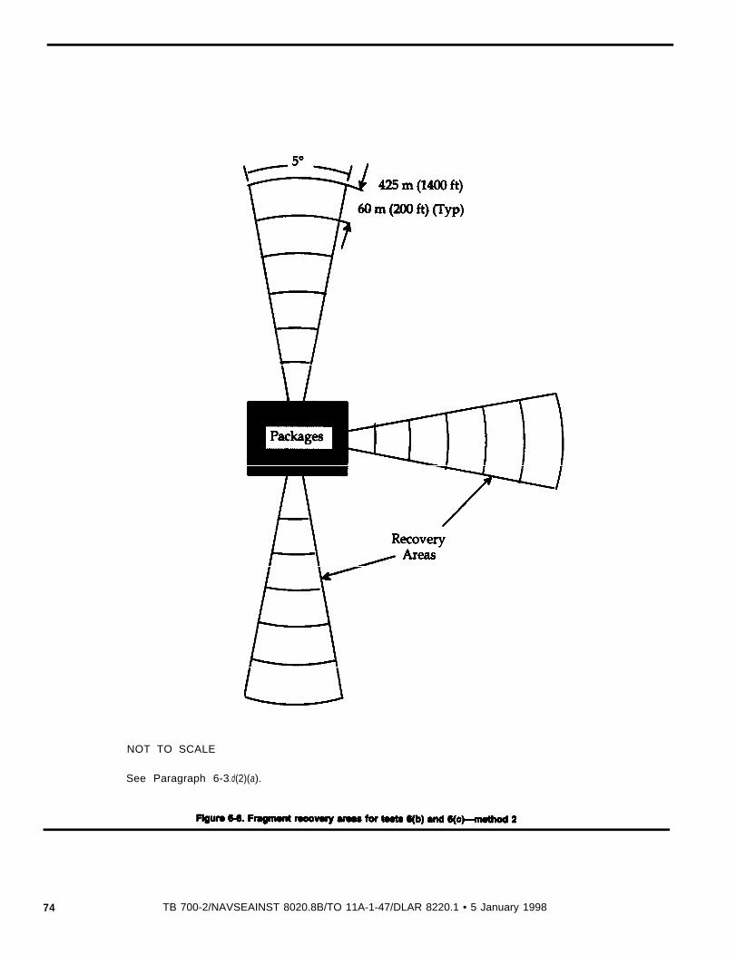
Figure 6-6. Fragment
NOT TO SCALE
See Paragraph 6-3.d(2)(a).
74 TB 700-2/NAVSEAINST 8020.8B/TO 11A-1-47/DLAR 8220.1 • 5 January 1998

Figure 6-7. Sample
TB 700-2NAVSEAINST 8020.8B/TO 11 A-1-47/DLAR 8220.1 • 5 January 1998 75
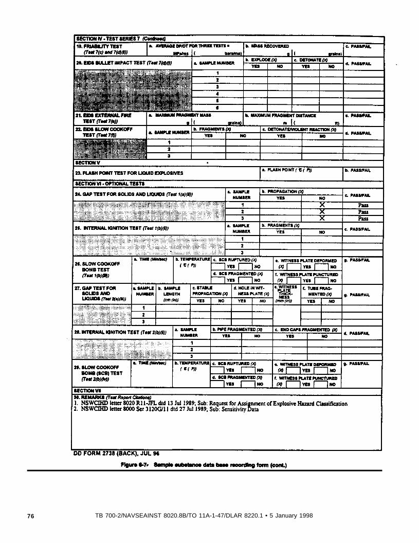
Figure 6-7. Sample
76 TB 700-2/NAVSEAINST 8020.8B/TO 11A-1-47/DLAR 8220.1 • 5 January 1998
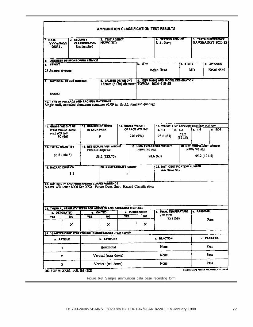
Figure 6-8. Sample ammunition data base recording form
TB 700-2/NAVSEAINST 8020.8B/TO 11A-1-47/DLAR 8220.1 • 5 January 1998 77
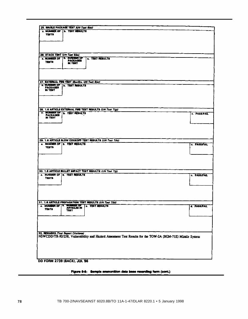
Figure 6-8. Sample
78 TB 700-2/NAVSEAINST 6020.8B/TO 11A-1-47/DLAR 8220.1 • 5 January 1998
Figure 6-9. Solid
NOTE: Need only test up to card gap dimension that just exceeds the web thickness of thepropellant in the rocket motor.
See Paragraph 6-6c( l ) .
79TB 700-2/NAVSEAINST 8020.8B/TO 11A-1-47/DLAR 8220.1 • 5 January 1 1998
Figure 6-10. Super
NOT TO SCALE
See Paragraph 6-6.c(1)(c).
80 TB 700-2/NAVSEAINST 8020.8B/TO 11A-1-47/DLAR 8220.1 • 5 January 1998
Chapter 7
Interim hazard classification
7-1. GeneralInterim hazard classifications are assigned for a variety of reasons.For example, during the course of programs for the acquisition ofnew explosives and ammunition items, explosive substances anddevices must be transported from places where they arc manufac-tured or assembled to testing facilities. Typically, these shipmentsare made at times during the development cycle when hardwareconfigurations are subject to frequent significant changes. See para-graph 1-7 for shipment of laboratory samples.
a. Quantities of test items sufficient to support STANAG 4123(App A, Ref 2) and DOD storage hazard classification tests arcnormally not available. Furthermore, extensive testing may not beeconomically justifiable to support one or a few shipments of suchdevelopmental configurations.
b. Consequently, it is frequently necessary to hazard classify ex-plosive items on an interim basis with less information than isusually available regarding production items that ate ready for re-lease into the military inventory. This chapter includes guidancepertaining to responsibilities and procedures for the determination.documentation, and administrative control of interim hazardclassifications.
7-2. Authoritya. The organization sponsoring development of, or first adopting
for use, an explosive substance or assembly is responsible for pro-viding the requisite data to the cognizant interim hazard classifica-tion authority for each new interim hazard classification or renewalrequired.
b. DoD or U.S. Department of Energy (DOE) Interim HazardClassification of an ammunition and explosive must be approved(by signature) by one of the following persons:
(1) U.S. Army.
Chief, Explosives Safety Test ManagementU.S. Army Technical Center for Explosives SafetyATTN: SIOAC-ESTSavanna, IL 61074-9639
(2) U.S. Navy.
Director, Weapons and Explosives Safety DivisionATTN: N71Naval Ordnance Center23 Strauss AvenueIndian Head, MD 20640-5555
(3) U.S. Air Force.
Air Force Safety CenterATTN: SEWV9700 Avenue G
(d) Chief, Safety office.
Kirtland AFB, NM 87117-5670
(4) U.S. Department of Energy.
Chief, safety officeU.S. Army Aviation and Missile CommandATTN: AMSAM-SFRedstone Arsenal, AL 35898-5130
(a) Doctor, Occupational Safety and Health Division.(e) Chief, Safety Office.
Director, Occupational Safety and Health DivisionU.S. Department of EnergyAlbuquerque Operations OfficeAlbuquerque, NM 97115-5400
Chief, safety OfficeU.S. Army Space and Strategic Defense CommandATTN: CSSD-TC-WSP.O. Box 1500
(b) Program Manager, Hazardous Materials Transportation. Huntsville, AL 35807-3801
Program Manager, Hazardous Materials TransportationU.S. Department of EnergyOakland operations OfficeOakland, CA 94612-5208
c. For DoD, the names of the persons holding the above listedpositions or their alternate will be provided, through the DDESBand the Military Traffic Management Command (MTMC). to theAssociate Administrator for Hazardous Materials Safety, MaterialsTransportation Bureau, RSPA/DGT, 400 7th Street, S.W., Washing-ton, DC 20590. MTMC will furnish notification that DoD hasplaced the names on file at DoT.
d. For DOE, the names of the persons holding the above listedpositions or their alternate will be provided through the Transporta-tion Management Division (TMD) EM-261. to the Associate Ad-ministrator for Hazardous Material Safety, Materials TransportationBureau, RSPA/DOT, 400 7th Street SW.. Washington, DC 20590,on a current basis. TMD will furnish notification that DGE hasplaced the names on file at DOT.
e. The chiefs of the U.S. Army, U.S. Navy and U.S. Air Forceoffices identified in Appendix A, Reference 3 may, with DDESBconcurrence,. authorize additional persons to grant (by signature)interim hazard classification approvals, subject to all the conditionsand procedures of this chapter. At the time of publication theseauthorized persons arc:
(1) U.S. Army.(a) Chief, System Safety Office.
Chief, System Safety OfficeU.S. Army Armament Research, Development, and Engineering
CenterATTN: AMSTA-AR-QASPicatinny Arsenal, NJ 07806-5000
(b) Chief. Safety Office.
Chief, safety OfficeU.S. Amy Edgewood Research, Development, and Engineering Cen-
terATTN: SCBRD-GDR-SAberdeen Proving Ground, MD 21010-5423
(c) Chief, Infrastructure Management Division.
Chief, Infrastructure Management DivisionU.S. Army Research Laboratory CommandATTN: AMSRL-CS-AL-RK2800 Powder Mill RoadAdelphi, MD 20783-1145
TB 700-2/NAVSEAINST 8020.8B/TO 11A-1-47/DLAR 8220.1 • 5 January 1998 81

(2) U.S Navy.(a) Indian Head Division.
Indian Head DivisionNaval Surface Warfate CenterATTN: Code 041B101 Strauss Ave.Indian Head. MD 20640-5035
(6) Program Management Office.
Program Management OfficeStrategic Systems Programs DetachmentP.O. Box 157Magna UT 84044-0157
(3) US. Air Force.(a) HQ Ogden Air Logistics Center.
HQ Ogden Air Logistics CenterATTN: LIWOS (Chief, Explosives Safety Team)6043 Elm Lane (Bldg 1246Hill AFB, UT 84056-5819
(6) Chief, Systems Safety.
Chief, systems safetyAir Force Development Test CenterATTN: AFDTC/SESEglin AFB, FL 43542-6817
f. The names of persons to whom approval authority is delegatedwill be provided to the Associate Administrator for HazardousMaterials Regulation (DDT) and to the Department of Defense Ex-plosives Safety Board (DDESB-KT), on a current basis. Acknowl-edgement from MTMC that DOD has placed the names on file withDOT is required.
g. The approval authority for DDE interim hazard classificationsmay not be delegated. Interim hazard classifications must be signedby one of the persons designated in paragraph 7-2b (4) or theiralternates.
7-3. Limitationsa. Interim hazard classifications assigned to substances must he
supported by results from Series 3 tests (para 5-4). In order toobtain an interim Hazard Division 1.3 classification then the follow-ing two tests also need to be conducted.Note. Use format given by example in Figure 6-7 to report results.
(1) Teat 2(a) (iii)--Use Gap Test for Solids and Liquids (para5-3a) with a 14 cm (5.5 in) tube (and sample) length and a 9.5 mm(3/8 in) thick witness plate. The substance is interim hazard classi-fired as Hazard Division 1.1 if a positive (+) response is obtainedwith a PMMA gap greater than or equal to 17.78 mm (0.7000 in -70cards); otherwise, the substance may be interim hazard classified asHazard Division 1.3. The U.S. Army Armament Research, Development and Engineering Center (ARDEC) Solid Propellant Shock Ini-tiation Sensitivity Test (App A. Ref 16) is an acceptable alternatetest for solid gun propellants. A solid gun propellant is interimclassified as Hazard Division 1.1 if the reaction front propagatessteadily with gap greater than or equal to 7.6 mm (0.3 in)with the ARDEC test; if the reaction front velocity is decaying, thenthe solid gun propellant may be interim classified as Hazard Divi-sion 1.3.
(2) Test 5(a)-Cap Sensitivity Teat (para 5-6a). The substance isinterim hazard classified as Hazard Division 1.1 if a positive (+)
response is obtained with a standard detonator otherwise, the sub-stance may be interim hazard classified as Hazard Division 1.3.
b. Interim hazard classificatton (which must include an apptopri-ate compatibility group) may be issued for a period up to one year.Extension beyond one year will require a request from the origina-tor, with justification, for renewal by the issuing organization. In-terim hazard classifications need not be submitted to DOT for filing.
c. Any Change in packaging or explosive components in an itemwill require reexamination of the item by the cognizant interimhazard classification authority listed in this chapter in order to ascer-tain the need for revision of the interim hazard classitication.
d. Interim hazard classifications are not recognized for interna-tional shipments by commercial carrier. When international shipmeat by commercial carrier is necessary for ammunition andexplosives without final DOD hazard classifications, a DOT Classifi-cation of Explosives with EK number assignment is required. (Seepara 3-1b). Interim hazard classifications and justifications for inter-national shipment, required in conjunction with a request for a DOTClassification of Explosives with EK number assignment may beissued for a period of up to two years.
e. Any incident involving loss of contents of the package must bereported to the Associate Administrator for Hazardous MaterialsRegulations, DOT; the Chairman DDESB, or the DDE, Director.TMD; and the authority granting the interim as listed in 7-26.
f. The interim hazard classification procedures apply only to DoDagencies and DoD contractors, or to DOE and DDE contractors,raspectively.
7-4. Documentationa The following data, as applicable, will be provided as a part of
the interim hazard classification request:(1) Item nomenclature.(2) Part numbers.(a) Prime Contractor.(b) vendor.(3) National stock number.*(4) System the item is associated with.(5) Next higher assembly item is used with.(6) Size of unpackaged item.(7) Weight of unpackaged item.(8) Explosive compositions.(9) Net explosive weight.(10) Physical description of item.(11) Functional description of item.(12) Packaging data.(13) Description of fuze safety features.
Note. * Unique contractor part numbers or product codes are allowed forinterim hazard classifications.
b. A central file will he maintained by each organization towhich interim hazard classification authority is delegated. The docu-mentation of each hazard classificaton will be kept in a mannerpermitting rapid retrieval for as long as shipments or storage of theconfiguration may be necessary. A copy of the hazard classifrCrrtonwill be expeditiously furnished, upon receipt of a proper request, toany required to store or transport an item that has beenassigned an interim hazard classification.
c. A copy of each DoD intaim hazard classification must beprovided to the Chairman DDESB. A copy of each DDE interimhazard classification must ‘be provided to the Director, TMD and tothe chairman DDE Explosive Safety Committee.
d. A copy of the applicable DoD or DDE interim hazard classifl-cation approval must be carried aboard each vehicle used to trans-port ammunition and explosives covered by this chapter.
e. Par DDE, shipments. by cargo aircraft may only be transportedby an air carrier authorized by an exemption to carry explosives.The air carrier, exemption held by the carrier, and type of explosiveto be carried, must be identified to and approved in writing by theOffice of Hazardous Materials Exemptions and Approvals prior to
82 TB 700-2/NAVSEAINST B020.8B/TO 11A-1-47/DLAR 8220.1 • 5 January 1998

Table 8-1
each shipment, or be authorized by provision of an authorized DOTexemption.
Chapter 8
forwarded to the Director, U.S. Army Technical Center for Explo-sives Safety, ATTN: SIOAC-EST, Savanna, IL 61074-9639. Areview of the information will be performed to determine accepta-bility of the entry and for compliance with the procedures in thispublication.
Joint hazard classification system
g-l. IntroductionThis chapter provides information and procedures concerning hazardclassification data in the Joint Hazard Classification System (JHCS).hereinafter referred to as the JHCS.
c. The Director, U.S. Army Technical Center for ExplosivesSafety, will be responsible for distribution of the JHCS printouts toDODCs, world-wide distribution of the quarterly printed JHCS mi-crofiche, inputting data into the JHCS, and maintaining the JHCS toinclude the on-line service.
8-2. Background Joint Hazard Classification System control recorda. The JHCS is a data base containing hazard classification and
safety data for explosive items, ammunition and ammunition relateditems (i.e., items containing some Class 1 material) of the DODCs.The information contained in the JHCS is necessary for safe storageand transportation. The JHCS was established to promote consis-tency among DoD hazard classification actions, to eliminate dupli-cation and conflict among component hazard classificationassignments, and to provide a single source document of authorita-tive and controlled hazard classification data for the entire DoD.
b. The JHCS contains the following data elements for DoD ex-plosive items, ammunition and ammunition-related items:
(1) DODC code - this code indicates which component is theproponent of an item’s hazard classification.
(2) Tri-Service coordination code - this code indicates whetheror not Tri-Service coordination has been completed.
(3) Item nomenclature.(4) Department of Defense identification code (DODIC), Locally
Assigned Ammunition Reporting Code (LARC), or Navy Ammuni-tion Logistic Code (NALC).
(5) National Stock Number (NSN).(6) DOD hazard division transportation and storage Compatibility
Group (CG).(7) United Nations (UN) Serial Number.(8) Department of Transportation (DOT) hazard class (pre-
1991).(9) DOT marking (with supplementary expansion ) (pre-1991).(10) DOT label (pre-1991).(11) Hazard symbol.(12) High explosive weight (HEW) (in units of pounds and
kilograms).(13) Net propellant weight (NPW) (in units of pounds and
kilograms).
d. The JHCS will be distributed on microfiche on a quarterlybasis. The fiche is available for unlimited distribution. Anyone de-siring a copy of the microfiche and/or placement on automaticdistribution for the fiche should send a request to: Director, U.S.Army Technical Center for Explosives Safety, ATTN:SIOAC-ESM, Savanna, IL 610749639 (DSN 585-8710 or Com-mercial (815) 273-8710).
(14) Net explosive weight (NEW) - the total of all Class 1materials used for transportation purposes (in units of pounds andkilograms).
(15) Net explosive weight for Q-D (NEWQD) - that combina-tion of explosive weight and propellant weight used to determine theexplosive weight used for quantitydistance purposes (in units ofpounds and kilograms).
e. The JHCS is available through an on-line format. Contact thesame address and telephone numbers in the previous paragraph torequest access (password and login/ID)) and procedures. Contactmay be also made by electronic mail at [email protected] JHCS may also be accessed on the Hazard Classification HomePage at http://192.108.244.100/es/estic.html
(16) Part number and/or drawing number.c. The above data will be sorted in the following sequences for
output purposes:(1) NSN.(2) Federal Stock Class (FSC)/ DODI/National Item Identifica-
tion Number (NIIN).
8-4. Department of Transportation (DOT) changer
(3) Part number (drawing number)/NSN.(4) Alphabetical listing by Item Nomenclature.
a. In 1991 the DOT adopted into federal law a different systemfor hazard classification of dangerous goods. The new system isessentially that which is used by United Nations for the transporta-tion of dangerous goods. The total phase-in period for the newsystem is ten years. The 49 CFR (App A. Ref 3) has more detailedinformation regarding the different phase-in periods for specificsituations and should be consulted as the authoritative source. TheJHCS will continue to have the old DOT information for the entirephase-in period of ten years.
8-3. Responsibilities and proceduresa. A JHCS control record will be generated for any addition,
deletion or change to the JHCS. A sample of the data base record isprovided in Table 8-1. Each DODC is responsible for completingthe record with the appropriate data elements for the desired addi-tions, deletions and changes to the JHCS.
b. All completed control records for revising the JHCS will be
b. For new items added to the JHCS after April 1991, there willbe no DOT (old system) information added.
c. For those items added after April 1991, the DOT hazard classfor Class 1 items will be the DoD Hazard Division CompatibilityGroup. Any parenthetical values appearing in the DoD hazard classwill not be included in the DOT hazard class. For those items wherethe DoD Hazard Division Compatibility Group is other than Class 1
TB 7004NAVSEAINST 6020.8B/TO 11 A-1-47-/DLAR 8220.1 • 5 January 1998 83
(i.e., Class 2-9), the DOT class will consist only of the DOD HazardDivision. No Compatibility Group for Class 2-9 will be included inthe DOT hazard class, whereas, it will be for DOD.
d. For thoes items entered in the JHCS after April 1991, the DOTlabel for Class 1 items will be the word ‘Explosive” followed by theDOT hazard class (i.e., 1.2C). For Class 2-9 consult 49 CFR (AppA, Ref 3).
e. For those items entend after April 1991. the DOT containermarking for Class 1 items will consist of the Propar Shipping Name(as defined by the UN Serial Number), the UN Serial Number, andthe NSN or part number. The NSN or part number may be usedonly if it is directly traceable to a DOT assigned registration number(i.e., "EX" number). All of these data elements are in the JHCS.
8-5. Completion of control record far JHCS revisiona. Each element allows sufficient space for hazard classification
data. There are a total of 20 available data entries for each itementered into the JHCS.
b. Each data element and the available codes that are incorpo-rated on the record are provided in Table 8-2.
84 TB 7004NAVSEAINST 8020.8B/TO 11A-1-47/DLAR 8220.1 • 5 January 1998
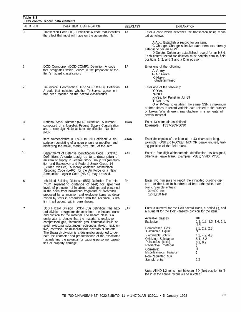
Table 8-2JHCS control record data elements
FIELD PO3 DATA lTEM IDENTIFICATION SlZE/CLASS EXPLANATlON
0 Transaction Code (TC), Definition: A code that identifies 1A Enter a code which describes the transaction being repor-the effect that input will have on the automated file. ted as follows:
1
2
3
4
5
6
7
DOD Component(DOD-COMP). Definition A code 1Athat designates which Service is the proponent of theItem’s hazard classification.
Tri-Service Coordination TRl-SVC-COORD) Definition 1A Enter one of the following:A code that indicates whether Tri-Service agreement Y-Yeshas been reached on the hazard classification. N-NO
X-Yes, by Panel in Jul 89T-Not new
National Stock Number (NSN) Definition: A number 16ANcomposed of a four-digit Federal Supply Classificationand a nine-digit National Item Identification Number(NUN)
item Nomenclature (ITEM-NOMEN) Definition: A de-scription consisting of a noun phrase or modifier andidentifying the make, model, size. etc., of the Item.
43AN
Departmemt of Defense Identification Code ((DODIC) 4ANDefinition: A code assigned to a description of an item of supply in Federal Stock Group 13 (Ammunl-tion and Explosive) and Federal Stock Group 14(Guided Missiles). A locally Assigned AmmunitionRepotting Code (LARC) for the Air Force or a NavyAmmunition Logistic Code (NALC) may be used.
Inhabited Building Distance (IBD) Definition The mini- 2Nmum separating distance of feet) for specifiedlevels of protectton of inhabited buildings and personnelin the open from hazardous fragments or firebrandsproduced by ammunition and explosive items as deter-mined by tests in accordance with the Technical Bullet-tin. It will appear within parentheses.
DoD Hazard Division (DOD-HCD) Definition: The haz- 3ANard division designator denotes both the hazard classand division for the material. The hazard class is adesignator to denote that the material is explosive,compressed gas, flammable gas, flammable liquid orsolid, oxidizing substances, poisonous (toxic), radioac-tive, corrosive, or miscellaneous hazardous matertal.The (hazard) division is a designator assigned to de-note the character and predominance of the assoctatedhazards and the potential for causing personnel casual-ties or property damage.
A-Add. Establish a record for an item.C-Change. Change selective data elements already
establiahd for an NSN.D-Delete. Delete an established record for an NSN.
Each control record for deletion must contain data In fieldpositions 1, 2, and 3 and a D in position.
Enter one of the following:A-ArmyF-Air ForceK-NavyI-Undetermined
O or P-Yea, to establish the same NSN a maximumof three times to record variable data related to the numberof boxes War different manufacture In shipments ofcertain material.
Enter 13 numerals as defined:Example: 1337-269-5030
Enter description of the item up to 43 characters long.Example: IGNITER ROCKET MOTOR Leave unused, trail-ing position of the field blank.
Enter a four digit alphanumeric identification, as assigned,otherwise, leave blank. Examples: VB35; VY80; VY80.
Enter two numerals to report the inhabited building dis-term for the Item In hundreds of feet: otherwise, leaveblank. Sample entries:
04=400 feet12=1,200 feet
Enter a numeral for the Do0 hazard class, a period (.), anda numeral for the DoD (hazard) division for the item.
Available classes:Explosive:
Compressed Gas:Flammable Liquid:Flammable Solids:Oxidizing Substance:Poisonous (toxic)Radiactive material:Corrosive:Miscelleaneous Hazards:Non-Regulated N.RSample entry:
HD1.1, 1.2, 1.3, 1.4, 1.5,1.62.1, 2.2, 2.334.1, 4.2, 4.35.1, 5.26.1, 6.2789
1.2
Note. All HD 1.2 items must have an IBD (field position 6) fil-led in or the control record will be rejected.
TB 700-2/NAVSEAINST 8020.8.8B/TO 11 A-1-47/DLAR 8220.1 • 5 January 1998 85
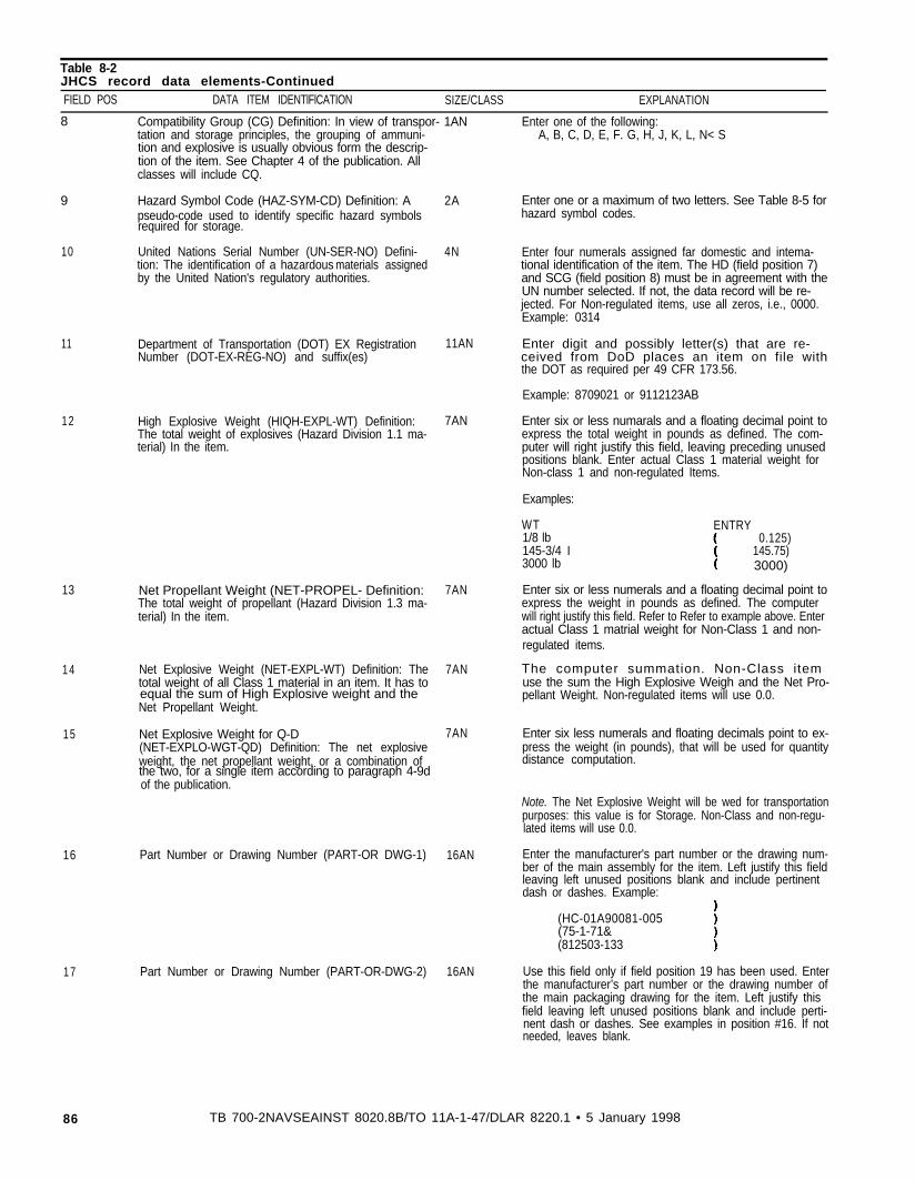
Table 8-2JHCS record data elements-ContinuedFIELD POS DATA ITEM IDENTlFlCATION SIZE/CLASS EXPLANATION
8 Compatibility Group (CG) Definition: In view of transpor- 1AN Enter one of the following:tation and storage principles, the grouping of ammuni-tion and explosive is usually obvious form the descrip-tion of the item. See Chapter 4 of the publication. Allclasses will include CQ.
9 Hazard Symbol Code (HAZ-SYM-CD) Definition: Apseudo-code used to identify specific hazard symbolsrequired for storage.
10 United Nations Serial Number (UN-SER-NO) Defini-tion: The identification of a hazardous materials assignedby the United Nation's regulatory authorities.
11
12
13
14
15
16
17
Department of Transportation (DOT) EX RegistrationNumber (DOT-EX-REG-NO) and suffix(es)
High Explosive Weight (HIQH-EXPL-WT) Definition: 7ANThe total weight of explosives (Hazard Division 1.1 ma-terial) In the item.
Net Propellant Weight (NET-PROPEL- Definition: 7ANThe total weight of propellant (Hazard Division 1.3 ma-terial) In the item.
Net Explosive Weight (NET-EXPL-WT) Definition: The 7ANtotal weight of all Class 1 material in an item. It has toequal the sum of High Explosive weight and theNet Propellant Weight.
Net Explosive Weight for Q-D 7AN(NET-EXPLO-WGT-QD) Definition: The net explosiveweight, the net propellant weight, or a combination ofthe two, for a single item according to paragraph 4-9dof the publication.
Part Number or Drawing Number (PART-OR DWG-1) 16AN
Part Number or Drawing Number (PART-OR-DWG-2) 16AN
A, B, C, D, E, F. G, H, J, K, L, N< S
2A Enter one or a maximum of two letters. See Table 8-5 forhazard symbol codes.
4N Enter four numerals assigned far domestic and intema-tional identification of the item. The HD (field position 7)and SCG (field position 8) must be in agreement with theUN number selected. If not, the data record will be re-jected. For Non-regulated items, use all zeros, i.e., 0000.Example: 0314
11AN Enter digit and possibly letter(s) that are re-ceived from DoD places an item on file withthe DOT as required per 49 CFR 173.56.
Example: 8709021 or 9112123AB
Enter six or less numarals and a floating decimal point toexpress the total weight in pounds as defined. The com-puter will right justify this field, leaving preceding unusedpositions blank. Enter actual Class 1 material weight forNon-class 1 and non-regulated Items.
Examples:
WT ENTRY1/8 lb 0.125)145-3/4 I 145.75)3000 lb 3000)
Enter six or less numerals and a floating decimal point toexpress the weight in pounds as defined. The computerwill right justify this field. Refer to Refer to example above. Enteractual Class 1 matrial weight for Non-Class 1 and non-regulated items.
The computer summation. Non-Class itemuse the sum the High Explosive Weigh and the Net Pro-pellant Weight. Non-regulated items will use 0.0.
Enter six less numerals and floating decimals point to ex-press the weight (in pounds), that will be used for quantitydistance computation.
Note. The Net Explosive Weight will be wed for transportationpurposes: this value is for Storage. Non-Class and non-regu-lated items will use 0.0.
Enter the manufacturer's part number or the drawing num-ber of the main assembly for the item. Left justify this fieldleaving left unused positions blank and include pertinentdash or dashes. Example:
(HC-01A90081-005(75-1-71&(812503-133
Use this field only if field position 19 has been used. Enterthe manufacturer’s part number or the drawing number ofthe main packaging drawing for the item. Left justify thisfield leaving left unused positions blank and include perti-nent dash or dashes. See examples in position #16. If notneeded, leaves blank.
86 TB 700-2NAVSEAINST 8020.8B/TO 11A-1-47/DLAR 8220.1 • 5 January 1998
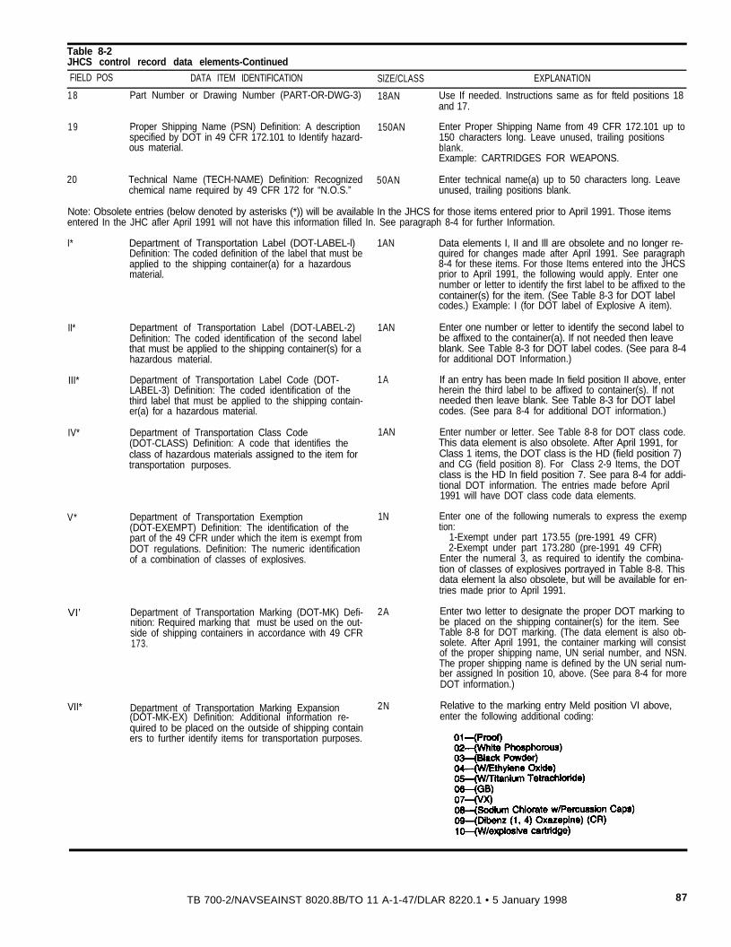
Table 8-2JHCS control record data elements-Continued
FIELD POS DATA ITEM IDENTIFICATION SlZE/CLASS EXPLANATION
18 Part Number or Drawing Number (PART-OR-DWG-3) 18AN Use If needed. Instructions same as for fteld positions 18and 17.
19 Proper Shipping Name (PSN) Definition: A description 150AN Enter Proper Shipping Name from 49 CFR 172.101 up tospecified by DOT in 49 CFR 172.101 to Identify hazard- 150 characters long. Leave unused, trailing positionsous material. blank.
Example: CARTRIDGES FOR WEAPONS.
20 Technical Name (TECH-NAME) Definition: Recognized 50AN Enter technical name(a) up to 50 characters long. Leavechemical name required by 49 CFR 172 for “N.O.S.” unused, trailing positions blank.
Note: Obsolete entries (below denoted by asterisks (*)) will be available In the JHCS for those items entered prior to April 1991. Those itemsentered In the JHC afler April 1991 will not have this information filled In. See paragraph 8-4 for further Information.
I* Department of Transportation Label (DOT-LABEL-l)Definition: The coded definition of the label that must beapplied to the shipping container(a) for a hazardousmaterial.
II*
III*
IV*
V*
VI’
VII*
Department of Transportation Label (DOT-LABEL-2)Definition: The coded identification of the second labelthat must be applied to the shipping container(s) for ahazardous material.
Department of Transportation Label Code (DOT-LABEL-3) Definition: The coded identification of thethird label that must be applied to the shipping contain-er(a) for a hazardous material.
Department of Transportation Class Code(DOT-CLASS) Definition: A code that identifies theclass of hazardous materials assigned to the item fortransportation purposes.
Department of Transportation Exemption(DOT-EXEMPT) Definition: The identification of thepart of the 49 CFR under which the item is exempt fromDOT regulations. Definition: The numeric identificationof a combination of classes of explosives.
Department of Transportation Marking (DOT-MK) Defi-nition: Required marking that must be used on the out-side of shipping containers in accordance with 49 CFR173.
Department of Transportation Marking Expansion(DOT-MK-EX) Definition: Additional information re-quired to be placed on the outside of shipping containers to further identify items for transportation purposes.
1AN
1AN
1A
1AN
1N
2A
2N
Data elements I, II and Ill are obsolete and no longer re-quired for changes made after April 1991. See paragraph8-4 for these items. For those Items entered into the JHCSprior to April 1991, the following would apply. Enter onenumber or letter to identify the first label to be affixed to thecontainer(s) for the item. (See Table 8-3 for DOT labelcodes.) Example: I (for DOT label of Explosive A item).
Enter one number or letter to identify the second label tobe affixed to the container(a). If not needed then leaveblank. See Table 8-3 for DOT label codes. (See para 8-4for additional DOT Information.)
If an entry has been made In field position II above, enterherein the third label to be affixed to container(s). lf notneeded then leave blank. See Table 8-3 for DOT labelcodes. (See para 8-4 for additional DOT information.)
Enter number or letter. See Table 8-8 for DOT class code.This data element is also obsolete. After April 1991, forClass 1 items, the DOT class is the HD (field position 7)and CG (field position 8). For Class 2-9 Items, the DOTclass is the HD In field position 7. See para 8-4 for addi-tional DOT information. The entries made before April1991 will have DOT class code data elements.
Enter one of the following numerals to express the exemption:
1-Exempt under part 173.55 (pre-1991 49 CFR)2-Exempt under part 173.280 (pre-1991 49 CFR)
Enter the numeral 3, as required to identify the combina-tion of classes of explosives portrayed in Table 8-8. Thisdata element la also obsolete, but will be available for en-tries made prior to April 1991.
Enter two letter to designate the proper DOT marking tobe placed on the shipping container(s) for the item. SeeTable 8-8 for DOT marking. (The data element is also ob-solete. After April 1991, the container marking will consistof the proper shipping name, UN serial number, and NSN.The proper shipping name is defined by the UN serial num-ber assigned In position 10, above. (See para 8-4 for moreDOT information.)
Relative to the marking entry Meld position VI above,enter the following additional coding:
TB 700-2/NAVSEAINST 8020.8B/TO 11 A-1-47/DLAR 8220.1 • 5 January 1998 87
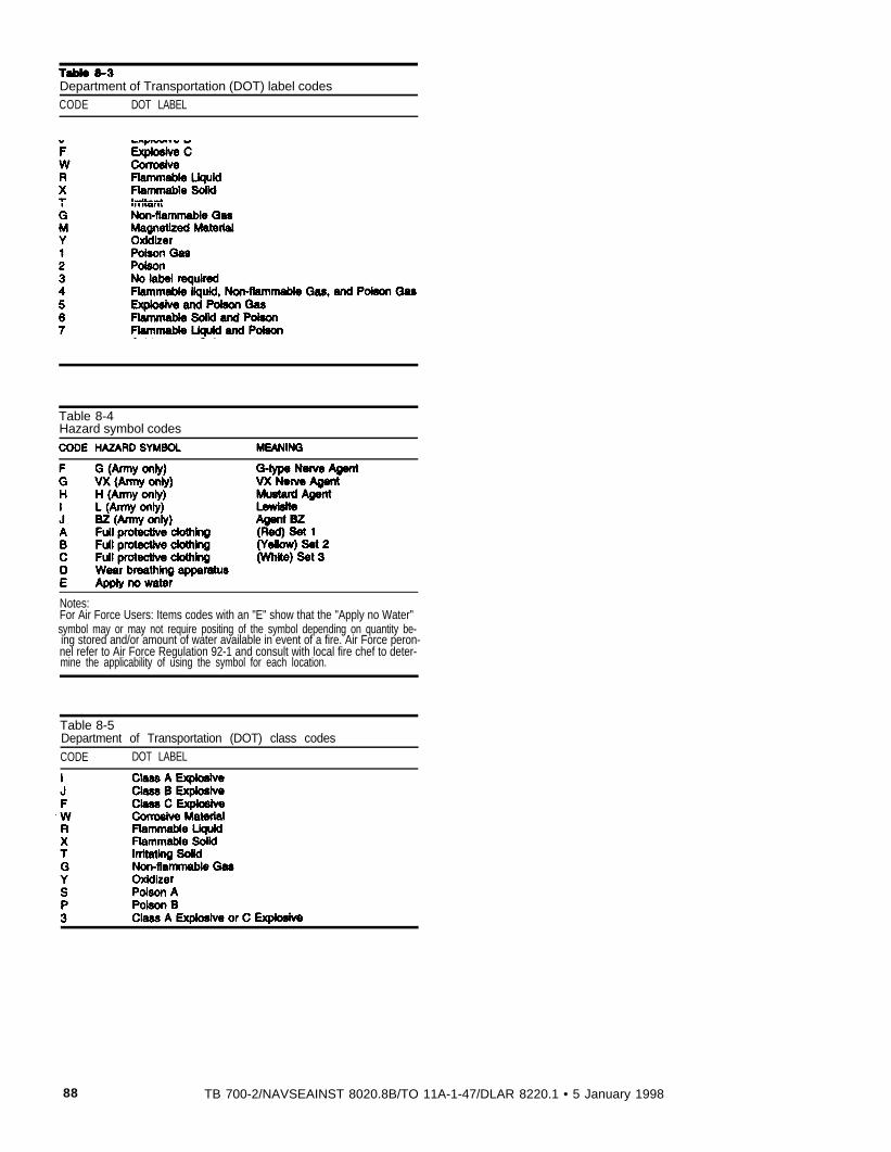
Table 8-3
Department of Transportation (DOT) label codesCODE DOT LABEL
Notes:For Air Force Users: Items codes with an "E" show that the "Apply no Water"symbol may or may not require positing of the symbol depending on quantity be-ing stored and/or amount of water available in event of a fire. Air Force peron-nel refer to Air Force Regulation 92-1 and consult with local fire chef to deter-mine the applicability of using the symbol for each location.
Table 8-4Hazard symbol codes
Table 8-5Department of Transportation (DOT) class codes
CODE DOT LABEL
88 TB 700-2/NAVSEAINST 8020.8B/TO 11A-1-47/DLAR 8220.1 • 5 January 1998
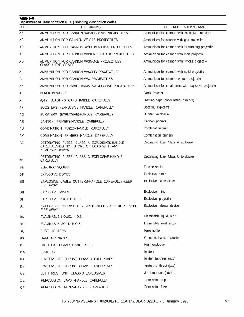
Table 8-6
Department of Transportation (DOT) shipping description codesCODE DOT MARKING DOT PROPER SHIPPING NAME
AB AMMUNITION FOR CANNON W/EXPLOSIVE PROJECTILES Ammunition for cannon with explosive projectile
AC
AD
AF
A G
AH
Al
AK
AL
AN
AP
A Q
AR
AU
AV
AZ
BB
BE
BF
BG
BH
BI
BJ
BN
CF
BO
BQ
BS
BT
BW
BX
BY
CB
CE
AMMUNITION FOR CANNON W/ GAS PROJECTILES
AMMUNITION FOR CANNON W/lLLUMlNATlNG PROJECTILES
AMMUNITION FOR CANNON W/INERT LOADED PROJECTILES
AMMUNITION FOR CANNON W/SMOKE PROJECTILES,CLASS A EXPLOSIVES
AMMUNITION FOR CANNON W/SOLID PROJECTILES
AMMUNITION FOR CANNON W/O PROJECTILES
AMMUNITION FOR SMALL ARMS W/EXPLOSIVE PROJECTILES
BLACK POWDER
(QTY) BLASTING CAPS-HANDLE CAREFULLY
BOOSTERS (EXPLOSIVE)-HANDLE CAREFULLY
BURSTERS (EXPLOSIVE)-HANDLE CAREFULLY
CANNON PRIMERS-HANDLE CAREFULLY
COMBINATION FUZES-HANDLE CAREFULLY
COMBINATION PRIMERS--HANDLE CAREFULLY
DETONATING FUZES, CLASS A EXPLOSIVES-HANDLECAREFULLY-DO NOT STORE OR LOAD WITH ANYHIGH EXPLOSIVES
DETONATING FUZES. CLASS C EXPLOSIVE-HANDLECAREFULLY
ELECTRIC SQUIBS
EXPLOSIVE BOMBS
EXPLOSIVE CABLE CUTTERS-HANDLE CAREFULLY-KEEPFIRE AWAY
EXPLOSIVE MINES
EXPLOSIVE PROJECTILES
EXPLOSIVE RELEASE DEVICES-HANDLE CAREFULLY- KEEPFIRE AWAY
FLAMMABLE LIQUID, N.O.S.
FLAMMABLE SOLID N.O.S.
FUSE LIGHTERS
HAND GRENADES
HIGH EXPLOSIVES-DANGEROUS
IGNlTERS
IGNITERS, JET THRUST, CLASS A EXPLOSIVES
IGNITERS, JET THRUST, CLASS B EXPLOSIVES
JET THRUST UNIT, CLASS A EXPLOSIVES
PERCUSSION CAPS -HANDLE CAREFULLY
PERCUSSION FUZES-HANDLE CAREFULLY
Ammunition for cannon with gas projectile
Ammunition for cannon with illuminating projectile
Ammunition for cannon with inert projectile
Ammunition for cannon with smoke projectile
Ammunition for cannon with solid projectile
Ammunition for cannon without projectile
Ammunition for small arms with explosive projectile
Black Powder
Blasting caps (show actual number)
Booster, explosive
Burster, explosive
Cannon primers
Combination fuze
Combination primers
Detonating fuze, Class A explosive
Detonating fuze, Class C Explosive
Electric squib
Explosive bomb
Explosive cable cutter
Explosive mine
Explosive projectile
Explosive release device
Flammable liquid, n.o.s.
Flammable solid, n.o.s.
Fuse lighter
Grenade, hand, explosive
High explosive
Igniters
Igniter, Jet-thrust (jato)
Igniter, jet-thrust (jato)
Jet thrust unit (jato)
Percussion cap
Percussion fuze
TB 7004NAVSEAINST 8020.8B/TO 11A-147/DLAR 8220.1 • 5 January 1998 89
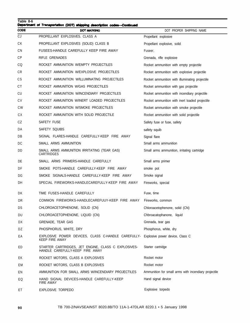
Table 8-6
DOT PROPER SHIPPING NAME
CJ
CK
CN
CP
CQ
CR
CS
CT
CU
CV
CW
CX
CZ
DA
DB
DC
DD
PROPELLANT EXPLOSIVES. CLASS A
PROPELLANT EXPLOSIVES (SOLID) CLASS B
FUSEES-HANDLE CAREFULLY KEEP FIRE AWAY
RIFLE GRENADES
ROCKET AMMUNITION W/EMPTY PROJECTILES
ROCKET AMMUNlTlON W/EXPLOSIVE PROJECTlLES
ROCKET AMMUNITION W/lLLUMlNATlNG PROJECTlLES
ROCKET AMMUNlTlON W/GAS PROJECTILES
ROCKET AMMUNITION W/lNCENDlARY PROJECTILES
ROCKET AMMUNlTlON W/INERT LOADED PROJECTILES
ROCKET AMMUNITION W/SMOKE PROJECTlLES
ROCKET AMMUNITION WITH SOLID PROJECTILE
SAFETY FUSE
SAFETY SQUIBS
SIGNAL FLARES-HANDLE CAREFULLY-KEEP FIRE AWAY
SMALL ARMS AMMUNlTlON
SMALL ARMS AMMUNlTlON IRRITATING (TEAR GAS)CARTRIDGES
DE SMALL ARMS PRIMERS-HANDLE CAREFULLY
DF SMOKE POTS-HANDLE CAREFULLY-KEEP FIRE AWAY
DG SMOKE SIGNALS-HANDLE CAREFULLY-KEEP FIRE AWAY
DH SPECIAL FIREWORKS-HANDLECAREFULLY-KEEP FIRE AWAY
DK
DR
DS
DU
DX
DZ
EA
TlME FUSES-HANDLE CAREFULLY
COMMON FIREWORKS-HANDLECAREFUUY-KEEP FIRE AWAY
CHLOROACETOPHENONE, SOLID (CN)
CHLOROACETOPHENONE, LIQUID (CN)
GRENADE, TEAR GAS
ED
EK
EM
EN
EQ
ET
90
PHOSPHORUS, WHITE, DRY
EXPLOSIVE POWER DEVICES, CLASS C-HANDLE CAREFULLY-KEEP FIRE AWAY
STARTER CARTRIDGES, JET ENGINE, CLASS C EXPLOSIVES-HANDLE CAREFULLY-KEEP FIRE AWAY
ROCKET MOTORS, CLASS A EXPLOSIVES
ROCKET MOTORS, CLASS B EXPLOSIVES
AMMUNITION FOR SMALL ARMS W/INCENDIARY PROJECTILES
HAND SIGNAL DEVICES-HANDLE CAREFULLY-KEEPFIRE AWAY
EXPLOSIVE TORPEDO
TB 700-2/NAVSEAINST 8020.8B/TO 11A-1-47DLAR 8220.1 • 5 January 1998
Propellant explosive
Propellant explosive, solid
Fuseer,
Grenada, rifle explosive
Rocket ammunition with empty projectile
Rocket ammunition with explosive projectile
Rocket ammunition with illuminating projectile
Rocket ammunition with gas projectile
Rocket ammunition with incendiary projectile
Rocket ammunition with inert loaded projectile
Rocket ammunition with smoke projectile
Rocket ammunition with solid projectile
Safety fuse or fuse, safety
safety squib
Signal flare
Small arms ammunition
Small arms ammunition, irritating cartridge
Small arms primer
smoke pot
Smoke signal
Fireworks, special
Fuse, time
Fireworks, common
Chloroacetophenone, solid (CN)
Chbroacatophanone, liquid
Grenada, tear gas
Phosphorus, white, dry
Explosive power device, Class C
Starter cartridge
Rocket motor
Rocket motor
Ammunition for small arms with incendiary projectile
Hand signal device
Explosive torpedo
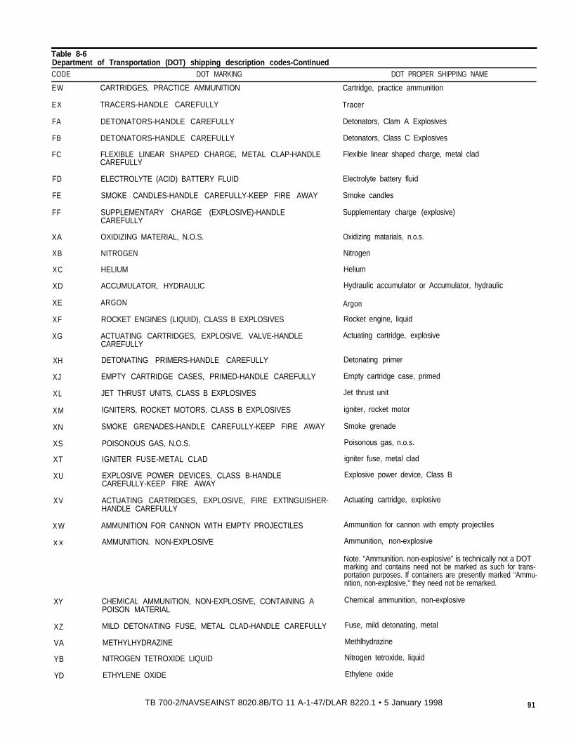
Table 8-6Department of Transportation (DOT) shipping description codes-ContinuedCODE DOT MARKING DOT PROPER SHIPPING NAME
EW
EX
FA
FB
FC
CARTRIDGES, PRACTICE AMMUNITION
TRACERS-HANDLE CAREFULLY
DETONATORS-HANDLE CAREFULLY
DETONATORS-HANDLE CAREFULLY
FLEXIBLE LINEAR SHAPED CHARGE, METAL CLAP-HANDLECAREFULLY
FD
FE
FF
ELECTROLYTE (ACID) BATTERY FLUID
SMOKE CANDLES-HANDLE CAREFULLY-KEEP FIRE AWAY
SUPPLEMENTARY CHARGE (EXPLOSIVE)-HANDLECAREFULLY
XA
XB
XC
XD
XE
XF
XG
OXIDIZING MATERIAL, N.O.S.
NITROGEN
HELIUM
ACCUMULATOR, HYDRAULIC
ARGON
ROCKET ENGINES (LIQUID), CLASS B EXPLOSIVES
ACTUATING CARTRIDGES, EXPLOSIVE, VALVE-HANDLECAREFULLY
XH
XJ
XL
XM
XN
XS
XT
XU
DETONATING PRIMERS-HANDLE CAREFULLY
EMPTY CARTRIDGE CASES, PRIMED-HANDLE CAREFULLY
JET THRUST UNITS, CLASS B EXPLOSIVES
IGNITERS, ROCKET MOTORS, CLASS B EXPLOSIVES
SMOKE GRENADES-HANDLE CAREFULLY-KEEP FIRE AWAY
POISONOUS GAS, N.O.S.
IGNlTER FUSE-METAL CLAD
EXPLOSIVE POWER DEVICES, CLASS B-HANDLECAREFULLY-KEEP FIRE AWAY
XV ACTUATING CARTRIDGES, EXPLOSIVE, FIRE EXTlNGUISHER-HANDLE CAREFULLY
X W
x x
AMMUNITION FOR CANNON WITH EMPTY PROJECTILES
AMMUNITION. NON-EXPLOSIVE
XY CHEMICAL AMMUNITION, NON-EXPLOSIVE, CONTAINING APOISON MATERIAL
XZ MILD DETONATING FUSE, METAL CLAD-HANDLE CAREFULLY
VA METHYLHYDRAZINE
YB NITROGEN TETROXIDE LIQUID
YD ETHYLENE OXIDE
Cartridge, practice ammunition
Tracer
Detonators, Clam A Explosives
Detonators, Class C Explosives
Flexible linear shaped charge, metal clad
Electrolyte battery fluid
Smoke candles
Supplementary charge (explosive)
Oxidizing matarials, n.o.s.
Nitrogen
Helium
Hydraulic accumulator or Accumulator, hydraulic
Argon
Rocket engine, liquid
Actuating cartridge, explosive
Detonating primer
Empty cartridge case, primed
Jet thrust unit
igniter, rocket motor
Smoke grenade
Poisonous gas, n.o.s.
igniter fuse, metal clad
Explosive power device, Class B
Actuating cartridge, explosive
Ammunition for cannon with empty projectiles
Ammunition, non-explosive
Note. “Ammunition. non-explosive” is technically not a DOTmarking and contains need not be marked as such for trans-portation purposes. If containers are presently marked “Ammu-nition, non-explosive,” they need not be remarked.
Chemical ammunition, non-explosive
Fuse, mild detonating, metal
Methlhydrazine
Nitrogen tetroxide, liquid
Ethylene oxide
TB 700-2/NAVSEAINST 8020.8B/TO 11 A-1-47/DLAR 8220.1 • 5 January 1998 91
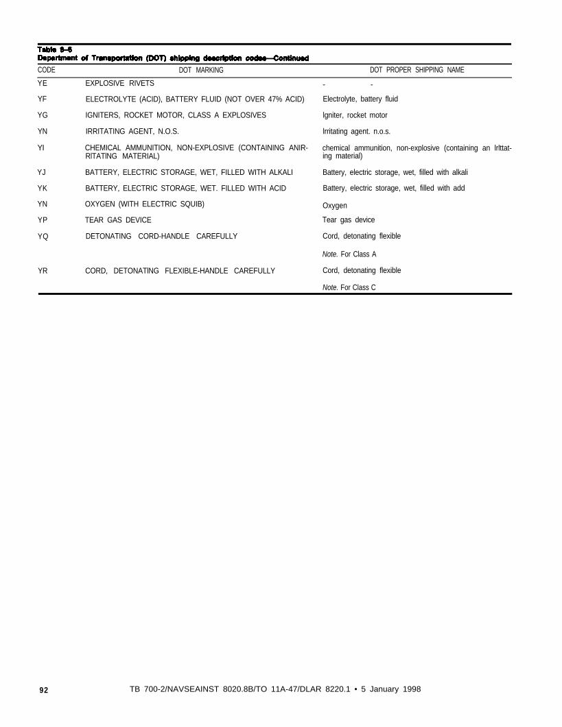
Table 8-6
CODE
YE EXPLOSIVE RIVETS
DOT MARKING DOT PROPER SHIPPING NAME
YF
YG
YN
YI
ELECTROLYTE (ACID), BATTERY FLUID (NOT OVER 47% ACID)
IGNITERS, ROCKET MOTOR, CLASS A EXPLOSIVES
IRRITATING AGENT, N.O.S.
CHEMICAL AMMUNITION, NON-EXPLOSIVE (CONTAINING ANIR-RlTATlNG MATERIAL)
- -
Electrolyte, battery fluid
lgniter, rocket motor
lrritating agent. n.o.s.
chemical ammunition, non-explosive (containing an lrlttat-ing material)
YJ
YK
YN
YP
YQ
YR
BATTERY, ELECTRIC STORAGE, WET, FILLED WITH ALKALI
BATTERY, ELECTRIC STORAGE, WET. FILLED WITH ACID
OXYGEN (WITH ELECTRIC SQUIB)
TEAR GAS DEVICE
DETONATING CORD-HANDLE CAREFULLY
CORD, DETONATlNG FLEXIBLE-HANDLE CAREFULLY
Battery, electric storage, wet, filled with alkali
Battery, electric storage, wet, filled with add
Oxygen
Tear gas device
Cord, detonating flexible
Note. For Class A
Cord, detonating flexible
Note. For Class C
92 TB 700-2/NAVSEAINST 8020.8B/TO 11A-47/DLAR 8220.1 • 5 January 1998
APPENDIX A
REFERENCES - related publications
1. Department of Defense Ammunition and Explosives Safety Standards. DoD6055.9-STD, (latest revision). Defense Printing Service Detachment Office, 700Robbins Avenue, Philadelphia, PA 19111. Phone: 215-697-2667; FAX 215-697-1462.
2. NATO Standardization Agreement (STANAG) 4123,Methods to Determine andClassify be Hazards of Military and Ammunition and Explosives, (latest revision). DefensePrinting Service Detachment Office, 700 Robbins Avenue, Philadelphia, PA 19111.Phone: 215-697-2667; FAX: 215-697-1462.
3. Code of Federal Regulations, Transportation, Title 49, Parts 100 to 177, (latestrevision. Superintendent of Documents, Government Printing .Office, Washington, DC20402; Phone: 202-512-1800.
4. Recommendations on the Transport of Dangerous Goods, ST/SG/AC, 10/1/latestreversion. United Nations Publication, New York, New York 10017; Phone: (212)963-8302.
5. Code of Federal Regulations, Protection of Environment, Title 40, Parts 260 to 299(latest revision). Superintendent of Documents, Government Printing Office,Washington, DC 20402; Phone: 202-512-1800.
6. Recommendations on the Transport of Dangerous Goods, Tests and Criteria.ST/SG/AC.10/11/latest revision. United Nations Publication, New York, New York10017; Phone: 212-963-8302.
7. Ribovich, J., Watson, R. W. and Gibson, F. C., Instrumented Card Gap Test,AIAA Journal, Vol 6, No. 7, pp. 1260-1263, 1968. Linda Hall Library, 5109Cherry Street, Kansas City, MO 64110-2498; Phone: 800-662-1545; FAX 816-926-8785.
8. ASME B16.11-1991, “Forged Fittings, Socket-Welding and Threaded,” AmericanSociety of Mechanical Engineers, New York, NY (latest revision); Phone: 212-705-7800.
9. ASTM D56-87, “Standard Test Method for Flash Point by Tag Closed Tester,”American Society for Testing and Materials, Philadelphia, PA (latest revision) Phone:215-299-5400.
10. Giglio-Tos, L. and Linnebrink, T., “Air Blast Pressure Measurement Systems andTechniques,” Minutes. 15th DDESB Seminar, 1359-1402, September 1973 (AD755-660). Defense Technical Information Center, Fort Belvoir, VA; Phone: 800-225-3842.
11. Kingery, C. N. and Bulmash, G., “Airblast Parameters from TNT Spherical Air
TB 700-2/NAVSEAINST 8020.8B/TO 11A-1-47/DLAR 8220.1 • 5 January 1998

Burst and Hemispherical Surface Burst,” ARBRL-TR-02555, April 1984 (ADB082713). Defense Technical Information Center, Fort Belvoir, VA; Phone: 800-225-3842.
12. McCleskey, F., “Quantity-Distance Fragment Hazard Computer Program(FRAGHAZ),” NSWC TR 87-59, February 1988. Naval Surface Warfare Center,Dahlgren Division, 17320 Dahlgren Road, Technical Library, Dahlgren, VA 22448-5000; Phone: 540-653-8351; FAX 540-653-7165.
13. Hay, J. C. and Watson, R. W., “Scaling Studies of Thermal Radiation Flux fromBurning Propellants,” Minutes, 25th DDEDB Seminar, Volume IV, pp. 233-668,August 1992. (AD A26116) Defense Technical Information Center, Fort Belvoir, VA;Phone: 800-225-3842.
14. MIL-STD-1751, Military Standard, Safety and Performance Tests for theQualification of Explosives (High Explosives, Propellants, and Pyrotechnics) (latestrevision). Defense Printing Service Detachment Office, 700 Robbins Avenue,Philadelphia, PA 19 111; Phone: 2 15-697-2667.
15. MIL-STD-2105, Military Standard, Hazard Assessment Tests for Non-NuclearMunitions (latest revision). Defense Printing Service Detachment Office, 700 RobbinsAvenue, Philadelphia, PA 19111; Phone: 215-697-2667.
16. Lu, Pai, “ARDEC Solid Gun Propellant Shock Initiation Sensitivity Test,”Minutes 26th DDESB Seminar, August 1994. CD-ROM, Defense TechnicalInformation Center, Fort Belvoir, VA; Phone: 800-225-3842.
TB 700-2/NAVSAINST 8020.8B/TO 11 A-1-47/DLAR 8220.1 • 5 January 1998
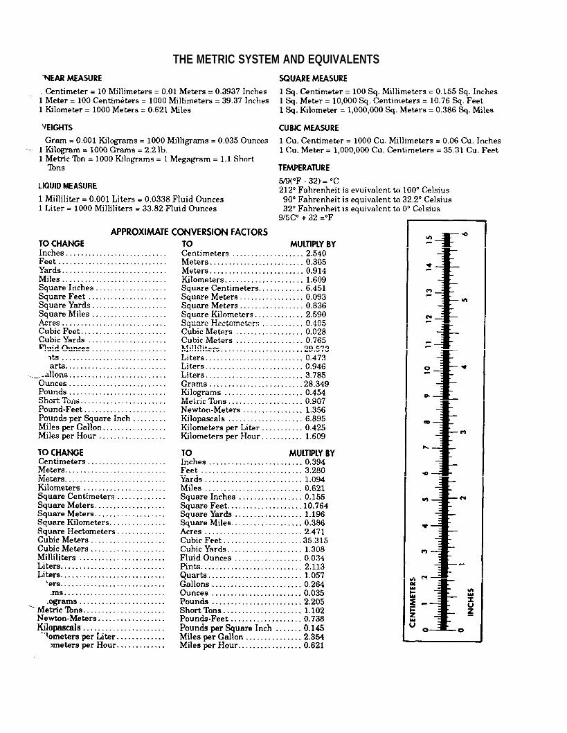
THE METRIC SYSTEM AND EQUIVALENTS

Unclassified PIN: 015286-000