Embed Size (px)
Citation preview
61 JTCG/ME-74-10
IJT CC"T/ME#
Joint Technical Coordinating Group
for
* Munitions Effectiveness
FLARE EFFECTIVENESS FACTORS:
"A GUIDE TO IMPROVED UTILIZATION
FOR
VISUAL TARGET ACQUISITION
TARGET ACQUISITION WORKING GROUP REPORT
0 4OO(O(VI144Best Available Copy
61 JTCG/ME-74-10
Joint Technical Coordinating Groupfor
Munitions Effectiveness
FO 8635-75-C-0004
FLARE EFFECTIVENESS FACTORS:A GUIDE TO IMPROVED
UTILIZATION FOR VISUALTARGET ACQUISITION
TARGET ACQUISITION WORKING GROUP REPORT
0
0 i ,Fo.... OC, 1Nov 7-350 November 1973
61 JTCG/ME-74-10
Reproduction for nonmilitary use of the information or Date shown on the title page (lower right comer) is forillustrations contained in this publication is not permitted identification only. This is not a distribution date.without specific approval of the issuing service. Processing time sometimes causes distribution to only
appear to have been delayed.
INSERT LATEST CHANGED PAGES. DESTROYSUPERSEDED PAGES.
I 'ST OF EFFECTIVE PAGES NOTE: On a changed page, the portion of the text affectedby the latest change is indicated by a vertical line, or other
Dates of issue for original and changed pages are: change symbol, in the outer margin of the page.
Original ... 0... November 1973
TOTAL NUMBER OF PAGES IN THIS PUBLICATION IS 90 CONSISTING OF THE FOLLOWING:
Page *ChangeNo. No.
Title ............... 0A ................ 0i- iv .... ............. 01-84 ............. 0
0
* Zero in this colunn indicates an original page.
A
61 JTCG/ME-74-10
S
PREFACE
This technical report documents an "in-house" survey conducted from September 1972 toMarch 1973 by the Aerospace Medical Research Laboratory. The work is part of a jointServices program on air-to-ground target acquisition. The research was undertaken in responseto a request from the Target Acquisition Working Group (TAWG) established by the JointTactical Coordinating Group for Munitions Effectiveness under the Joint Munitions Effec-tiveness Manual/Air-to-Surface. The request was for the publication of information which willbecome part of the Joint Munitions Effectiveness Manual and which pertains to the effectiveplanning and execution of flare missions for unaided air-to-ground visual target acquisition.
Current TAWG tasks include the definition of problem areas in airborne forward air controlleroperations, the description and effectiveness estimation of target markers, research on targetacquisition by flarelight, summary and synthesis of existing target acquisition field test data,and the description and evaluation of mathematical models of the visual target acquisitionprocess.
* The scope of the study was broadly defined by the TAWG steering committee composed ofRonald Erickson, Chairman (Naval Weapons Center), Major Robert Hilgendorf, Co-chairman(Wright-Patterson Air Force Base), Dr. Howland Bailey, Mathematical Model SubgroupChairman (Rand Corp.), Ronald Bruns (Naval Missile Center), V. Darryl Thornton (ElginAFB), Lt Col C. E. Waggoner (Brooks AFB), and Paul Amundson (Naval Weapons Center).The work was conducted by the TAWG Flare Research Subgroup. Dr. Shelton Macleod(Aerospace Medical Research Laboratory) was the principle investigator. The study wastechnically reviewed by other members of this Subgroup.
The aid of the following individuals in the preparation of this report is especially acknowledged:Mr. Carl W. Lohkamp, Research and Development Department, Naval Ammunition Depot,Crane, Indiana, reviewed the manuscript, provided most of the ideas for the introductorySummary of Applied Principles, and rewrote the section on Candle Composition; Mr. RobertB. Davis, Pyrotechnics Division, Picatinny Arsenal, Dover, New Jersey, reviewed the manu-script and provided a useful critique on the inadequacies of current pyrotechnic illuminationstandards.
S
• ', l i i i l | Pi
61 JTCG/ME-74-10
TABLE OF CONTENTSPage
Section,
INTRODUCTION 1Background 1Summary of Applied Principles for Effective Flare Utilization 1Military Applications of Illuminating Flares 4Target Acquisition Responses 4Description of Flare Dispensing Systems 5Summary of Factors Controlling Flare Effectiveness 8
II RESEARCH APPROACHES 10Flare Tunnel 10Tower Facility 10Field Test 10
Pyrotechnic Evaluation Range (PER) 10Observer Opinion Test 13Observer Performance Test 13
Terrain-Model Studies 13Math-Model Studies 15
III FLARE EFFECTIVENESS FACTORS 17Candle Composition 17
Particle Size 19Amount of Magnesium 19Altitude Effect 19Flare Diameter 22Flare Binder 22Flare Smoke 22
Flare Deployment Factors 22Ground Illumination Requirements 23Flare Altitude 25Burn-Rate 30Rate of Descent 30Flare Orientation 30Multiple Flare Systems 31Flare Shielding 33
Wind Drift 36Atmospheric Effects 39Target/Background Factors 43Observer Factors 43
IV CONCLUSIONS 47
AppendixesA Aircraft Flare Descriptions 53B Flare Questionnaire 80
References 48 0
.1i
61 JTCG/ME-74-10
LIST OF ILLUSTRATIONS
Figure Page1 MK-45 Aircraft Parachute Flare 6
2 MK-45 Illumination and Final Collapse Stages 7
3 Flare Tunnel 11
4 Flare Tower Facility 12
5 Pyrotechnic Evaluation Range 14
6 Terrain Model showing Observer and SimulatedFlare-Drop Device 16
7 Wavelength Spectrum of a Typical Magnesium Flare 18
8 Effects of Magnesium Particle Size on Flare BurningRate and Candlepower 20
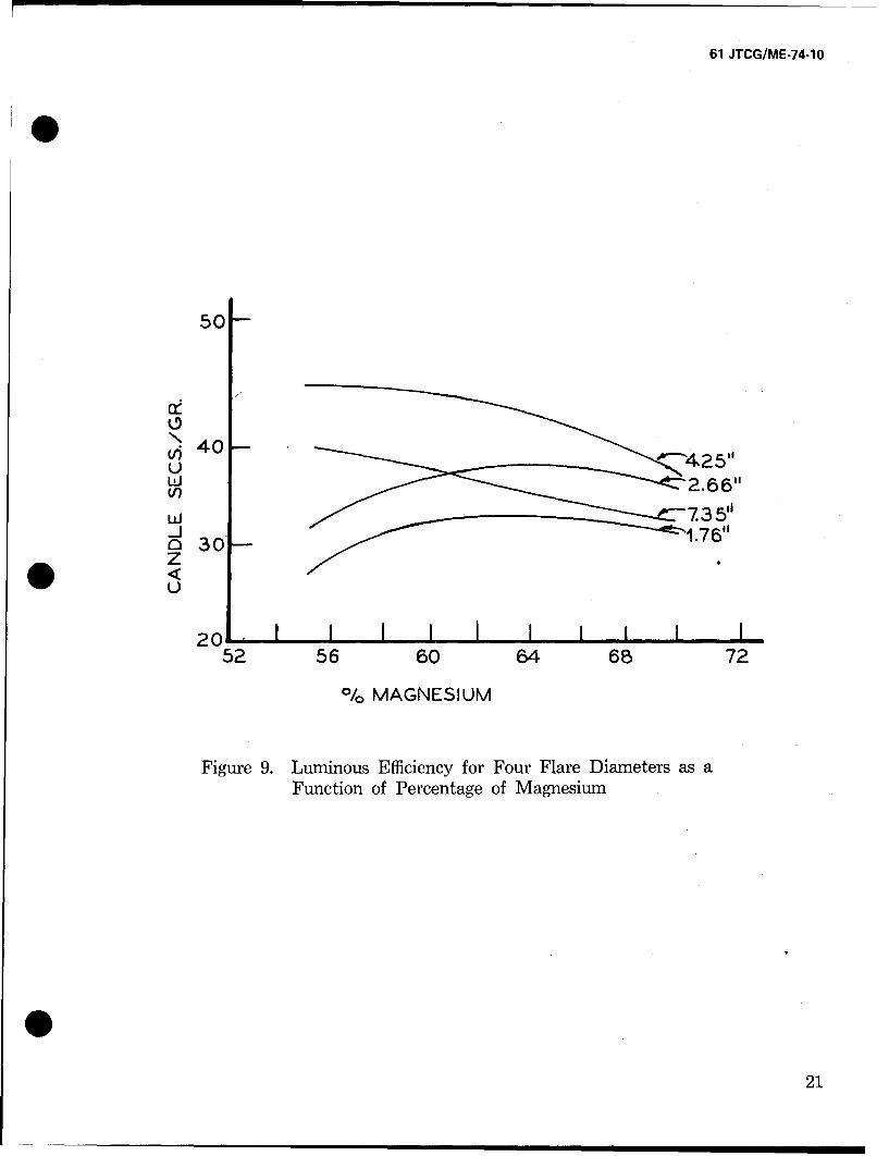
9 Luminous Efficiency for Four Flare Diameters as aFunction of Percentage of Magnesium 1 21
10 Ground Area Illuminated to 0.2 Footcandles by Flaresat various Heights and Intensities 27
11 Ground Area Illuminated to 0.2 Footcandles atOptimum Heights of Flares with Different Intensities 28
* 12 Radial Measures of Ground Illumination from thePyrotechnic Evaluation Range for the M335A1 atVarious Elevations 29
13 Machine Plotted Output for a Ground IlluminationContour of 0.5 Footcandles 34
14 A Shielded Flare at the Beginning and End of theBurn Period 35
15 Visibility Plot for Shielded and Unshielded Flaresat Different Flare-Observer-Target Angles 37
16 Luminous Intensity versus Degrees from PatternCenter for a 60-degree 45-inch Shield 38
17 Tolerable Wind Drift for Target Acquisition(See text for explanation) 40
18 Paths of Atmospheric Degradation for TargetVisibility under Flarelight 41
19 Effect of Atmosphere on Contrast under FlareIllumination 42
20 Illumination Required for Recognition as aFunction of Target Illumination Angle 46
iii-
61 JTCG/ME-74-10
Figure Page
A-1 XM170 Aircraft Parachute Flare 54
A-2 XM-715 Mechanical Time Fuze 55
A-3 XM-127 Aircraft Flare Dispenser 56
A-4 XM-15 Aircraft Dispenser and Flare 57
A-5 XM170 Aircraft Parachute Flare DeploymentSequence 58
A-6 M8A1 Aircraft Parachute Flare 61
A-7 M8A1 Aircraft Parachute Flare DeploymentSequence 62
A-8 LUU-2/B Aircraft Parachute Flare 64
A-9 LUU-2/B Flare Operation Sequence 66
A-10 MK-45 Aircraft Parachute Flare 67
A-11 MK-45 Flare, Aircraft, Parachute Launch andInitial Separation Stages 69
A-12 MK-45 Secondary Separation and IgnitionStages 70
A-13 MK-45 Illumination and Final Collapse Stages 71 0A-14 Aircraft Parachute VJare, MK24, Cross-Section 72
A-15 Attack Flare 75
A-16 Attack Flare Deployment Sequence 76
A-17 Briteye Flare Assy B-2 78
A-18 Briteye Flare Assembly B-2 79
0iv
61 JTCG/ME-74-1O
SECTION IINTRODUCTION
BACKGROUND
This document is responsive to a request from the Target Acquisition Working Group (TAWG)of the Joint Tactical Coordinating Group for Munitions Effectiveness for the publication ofinformation which will become part of the Joint Munitions Effectiveness Manual and whichpertains to the effective planning and execution of flare missions for unaided air-to-groundvisual target acquisition. The following ground rules have been adopted in interpretingTAWG's request and organizing the contents of this report. The data provided are intendedfor that community of interest within the Armed Forces which is concerned with research,engineering, planning or operational activities involving the design or deployment of illumi-nating flares for air-to-ground visual target acquisition.
Ideally this report should be a manual which provides the user with complete information forresearching, operating and evaluating current and future illuminating flare systems. However,such a compendium is now virtually impossible to produce, given the existing gaps andlimitations of data on flare effectiveness. Sufficient data that are valid, quantitative and appli-cable to all user needs simply do not exist. Nevertheless, within the past 10 years ground hasbeen broken and a considerable amount of relevant pyrotechnic and visual research has beengenerated by all three Services. This paper extracts, organizes and evaluates the data of thosestudies that appear to have immediate or potential user application. Accordingly, a research-centered document has been prepared providing the user with information, guidance\ andrecommendations that are primarily concept oriented rather than hardware oriented. Hope-fully, the reader will be able to select, interpret and apply those sections of the report that arerelevant to his particular problems.
Certain advantages may be derived from this approach: (a) It systematizes and integratesa wide variety of research efforts, thus increases the degree of impact on current user needs;(b) Rather than limiting the approach to the specific equipments or systems of a particularorganization, it permits a broader degree of generality applicable to the needs of many groupswithin all services; (c) It can result in stronger and more relevant interdependency betweenresearcher and user so that technological needs are better selected, stated and prioritized.
SUMMARY OF APPLIED PRINCIPLES FOR EFFECTIVE FLARE UTILIZATION
Although this report is primarily research oriented, stressing gaps in knowledge and the needfor empirically derived information, it would be a mistake to deny the reader those benefitsderived from practical experience which govern effective deployment of illuminating flaresystems. Such experience has led to certain "rules-of-thumb" which tend to pay off under arelatively wide range of conditions. Some of these working principles will be included hereinfor the benefit of those readers who participate directly in the planning or operation of flaremissions. These points are by no means exhaustive and are given in no particular order. Theyrepresent the kind of advice that a seasoned user would give the planner who is learning todeploy a flare system. Despite the likelihood that this advice will be generally beneficial, the
! ! .1
61 JTCG/ME-74-10
phrase "other things being equal" should be applied to all helpful hints of this type. Subse-quent sections of this document will be more concerned with these "other things."
Types of Flare Missions
As pointed out by Davis and Tyroler (1972), there are three general categories of missionsinto which the use of illuminating flares fall, and most applications are one or a combination ofthese categories:
1. Fixed Position. Here a predesignated target is at a known location and must be illuminatedas a basis for subsequent military action (e.g., strike or damage assessment).
2. Specific area. In this situation a specified area must be illuminated to such a level that, if aknown target is present, the observer has a high probability of recognizing it. This tactic iscommonly deployed in securing an area against infiltration by enemy troops.
3. Search. In this case one is concerned about finding known targets or targets of opportunityin a relatively large suspect area, e.g., searching for tanks or trucks along a road.
Flare deployment tactics will obviously differ for each of these situations. For effective targetacquisition, the number of flares, as well as the amount of illumination required per flarewill generally increase progressively (possibly by a factor of two) as one proceeds from theFixed Position to the Specific Area to the Search Situation. 0Multiple Flares
The need for multiple flare deployment (including the selection of number of componentunits and temporal spacing between them) depends largely upon mission requirements. Forthe Specific Area and Search Situations, multiple deployment patterns will usually be neces-sary. Suggested formulae for effective launch cycles under these conditions are given in reportsby Blunt and Schmeling (1968 pgs 57-63) and by Starrett (1964). Fixed-Position missions areunlikely to require launching more than two flares the same pass.
Atmospheric Effects
Because cloud formations greatly reduce the probability of target acquisition by scatteringand attenuating flare light, every attempt should be made to launch flares over openings incloud cover or beneath cloud layers.
Even a moderately restrictive meterological condition (i.e., a slight ground haze) which re-duces the meterological range by one-half is also likely to reduce the probability of detect-ing a target by the same amount.
Glare-Angle
The geometry of deployment should be such as to maintain a glare-angle (i.e., 'the angle *formed at the observers eye from respective lines of regard to the flare and the target) larger
2
61 JTCG/ME-74-10
than 7'. For smaller glare angles excessive veiling illumuination from the flare will obscure thevisual image of the target. In any case the observer should refrain from looking at the flare, sincethis can significantly impair his night vision for several minutes. During this time his ability toacquire targets will be reduced.
Flare Ignition Altitude
This should generally be kept as low as possible without sacrificing other requirements to(1) prevent glare, (2) maintain a sufficient bum-period to search for the target, and (3) avoidground-burning. Flares ignited at low altitudes provide iess opportunity for wind-drift andenemy-alert before the target is adequately illuminated. Moreover, a relatively low illuminatingsource, increases the probability of effectively silhouetting the target.
Relative position of Observer, Target and Flare.
If mission requirements emphasize the need for visual target acquisition, it is generally best todrop the flare on the far side of the target from the observer (i.e., back-lighting the target).Under these conditions it is most advantageous to not have the observer, target and flare inthe same vertical plane. A minimum lateral observer-offset of 15 degrees is recommended.
If, on the other hand, a higher priority is placed on the safety of the observational aircraft, theflare should be dropped between it and the target, thus providing an illuminating shield against
* hostile detection.
Illuminating Target Background.
Placement of flares should be such as to take full advantage of cues to target detection, i.e.,features of the environment (rivers, roads) which are invariably associated with certain typesof targets (boats, bridges, vehicles). If, on the other hand, features of the environment consti-tute clutter (i.e., irrelevant objects such as trees or cattle likely to be confused with targets),the level of flare illumination must be increased to minimize observer-error.
Slant Range Visibility
The probability of recognition approaches an unacceptable level at observer-to-target distances(slant ranges) where the visual angle subtended by the target is less than one minute of arc.A rapid estimation of this limiting distance is given by the formula D = 3500L where D is theobserver-to-target distance and L is the largest dimension of the target projected to the eye.At most practical slant ranges it will be virtually impossible for the aircraft observer to identifydiscrete personnel. Direct sighting of this small a target (which is able to effectively use groundcover) is generally not feasible.
Aircraft Speed
0 There is generally an inverse relationship (beyond some low limiting speed) between aircraft
3
61 JTCG/ME-74-10
velocity and probability of target acquisition. Hence observer aircraft speed should be main-
tained as slow as possible (within equipment or mission constraints).
Utilization of Wind
Flare light acquisition will generally be unfeasible during periods of exceptionally strong orgusty winds which blow the flarelight off the target. Nevertheless for moderate winds (up toabout 20 knots), where altitude profiles of wind velocity are available, flares may be advanta-geously dropped with wind-drift taken into account so as to drift over the target at the timeof most effective illumination or, possibly, to provide effective light while drifting over an ex-tended area.
Wind-Screen Condition
A surprising amount of degradation in the observer's ability to sight targets may be directlyattributable to the condition of the wind screen through which he is looking. Accumulated ef-fects of scratches, dirt and grease on this viewing media can reduce light transmission by asmuch as 50 percent. The transmissivity of the window material is also important and requireschecking.
MILITARY APPLICATIONS OF ILLUMINATING FLARES
The deployment of visual illuminating flares is part of a broad class of operations known asMilitary Pyrotechnics. This has been defined by Hart (1955) as a "category of ammunitionemployed primarily for the production of light, heat, smoke and sound for such typical nonde-structive purposes as battlefield illumination, signalling, marking, tracking, tracing, spotting,ignition, simulation and aerial night photography... produced as a result of chemical reactionscaused by the application of proper stimuli to chemical elements or compounds alone or inintimate mixtures. Military pyrotechnics are major aids and accessories in tactical operationsfor communications, warning, reconnaissance and the effective application of destructive fire-power, in strategic operations for intelligence, in supporting activities such as rescue operationsand troop training, in research and development of rocket powders and propellants, and in ex-ploration of the upper atmosphere."
Within the broader range of pyrotechnics this paper is concerned with the illumination flare, aground illumination system designed to be air-launched at night and to provide sufficient lightover designated areas for specific kinds of military operations to occur. Included here are suchdiverse activities as navigation, rendezvous, reconnaissance, target marking, ground support,search and rescue, disruption of enemy gunners, terminal guidance, and strike illumination.Note that for special applications flares may be designed to emit invisible irradiation. Here theflare emission enhances the use of infrared night vision aids for target acquisition by providingthe required type of background illumination.
TARGET ACQUISITION RESPONSES
Of prime concern in this report is the use of flares for air-to-ground unaided visual target acqui-sition from observational aircraft. A point worth stressing here is that the required kinds and *4
61 JTCG/ME-74-10
O levels of target acquisition responses can vary widely depending on the type of military appli-cation which the flare-light illumination supports. Thus illuminating a prelocated target placesa different visual requirement on the human observer (elicitation of a single preset confirmingreaction) than does the illumination of an area under surveillance (which requires search andthe possibility of alternative responses). Still another alternative would be the illumination ofsuspect areas for targets of opportunity, where an observer searches with even less knowledgeof what he is looking for. Differing military requirements can also dictate different levels ofresponse specificity. These have been categorized as: (1) Detection-merely locating an un-specified object, (2) Orientation--being able to discern the long and short dimensions of asuspect target, (3) Recognition- sufficient labeling of a target to establish the general class ofobjects to which it belongs (e.g., tank), (4) Identification-more precise categorization of atarget (e.g., an M-15).
In addition to the responses associated with labeling the target, target acquisition may alsoinvolve responses for gauging the relative or absolute location or distance of the target withrespect to the observer or other points of reference.
Mission requirements for visual target acquisition will also dictate the speeds with which ob-servers must respond and the relative cost of different types of response errors, i.e., errors oflocation, misidentifications or omissions.
) ,
For visual flares (as is the case for all other visual acquisition systems), the effectiveness of thetotal system, as well as its various components, is based largely on the extent to which systemoutputs in the form of target acquisition responses satisfy the information acquisition require-ments for which the system has been designed. In this case the responding unit is the eye andbrain of a human observer.
DESCRIPTION OF FLARE DISPENSING SYSTEMS
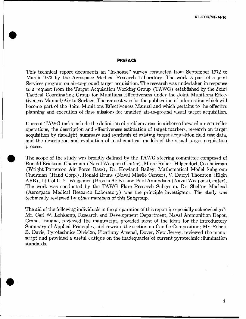
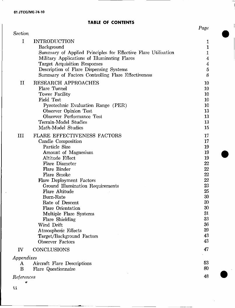
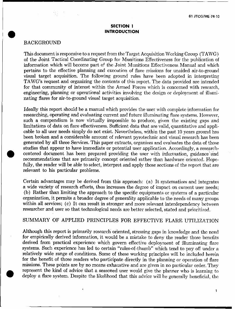
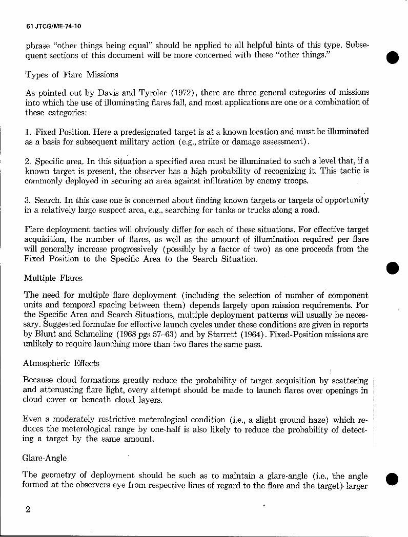
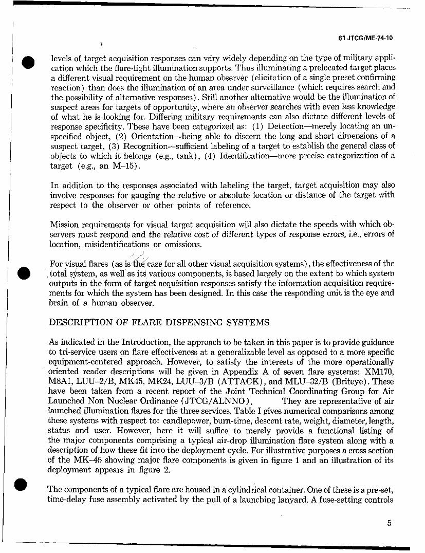
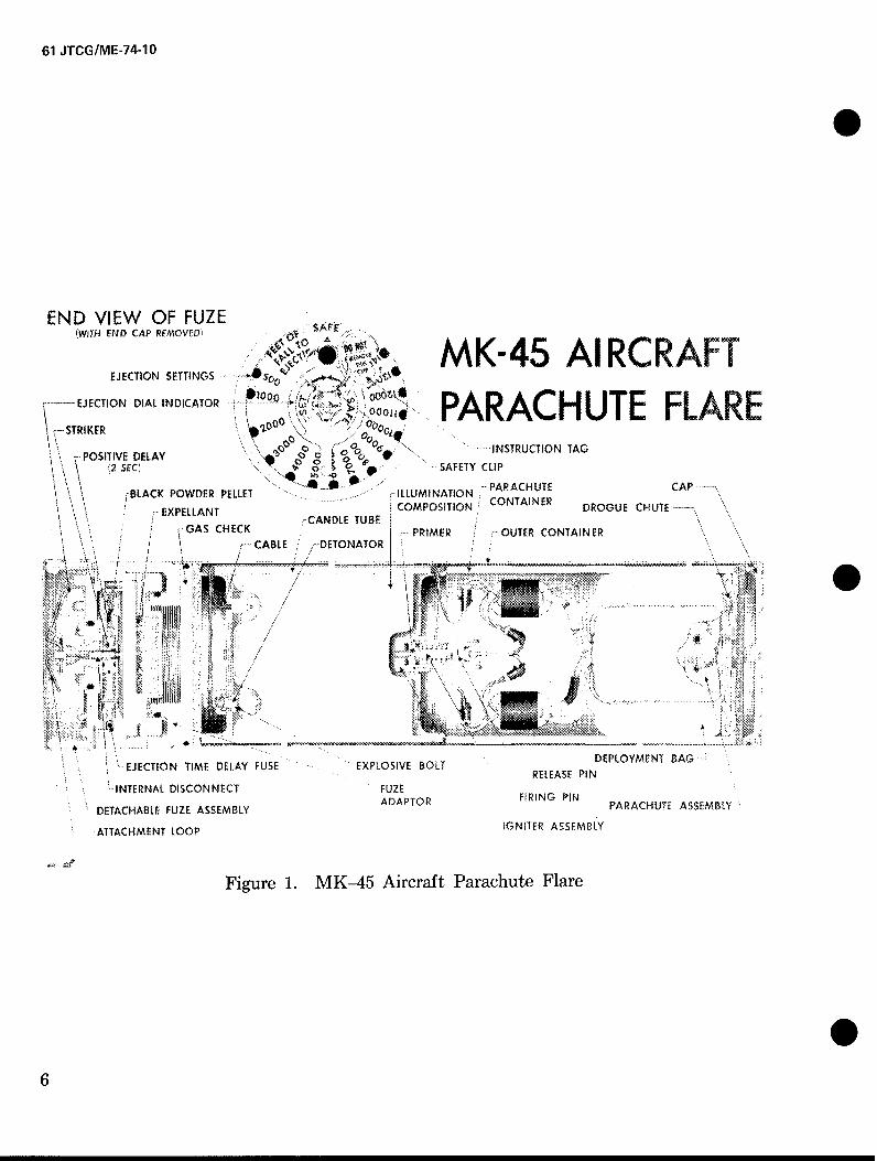
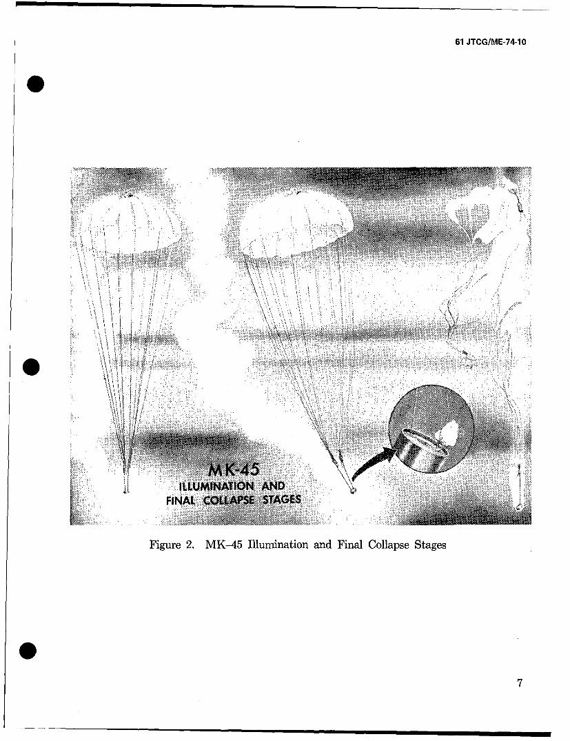
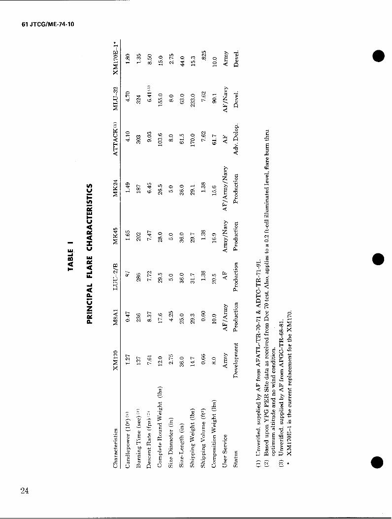
As indicated in the Introduction, the approach to be taken in this paper is to provide guidanceto tri-service users on flare effectiveness at a generalizable level as opposed to a more specificequipment-centered approach. However, to satisfy the interests of the more operationallyoriented reader descriptions will be given in Appendix A of seven flare systems: XM170,M8A1, LUU-2/B, MK45, MK24, LUU-3/B (ATTACK), and MLU-32/B (Briteye). Thesehave been taken from a recent report of the Joint Technical Coordinating Group for AirLaunched Non Nuclear Ordinance (JTCG/ALNNO). They are representative of airlaunched illumination flares for the three services. Table I gives numerical comparisons amongthese systems with respect to: candlepower, burn-time, descent rate, weight, diameter, length,status and user. However, here it will suffice to merely provide a functional listing ofthe major components comprising a typical air-drop illumination flare system along with adescription of how these fit into the deployment cycle. For illustrative purposes a cross sectionof the MK--45 showing major flare components is given in figure 1 and an illustration of itsdeployment appears in figure 2.
The components of a typical flare are housed in a cylindrical container. One of these is a pre-set,time-delay fuse assembly activated by the pull of a launching lanyard. A fuse-setting controls
5
61 JTCG/ME-74-10
END VIEW OF FUZE(WITH END CAP REMOVED) SAM FE
-45 Al RCRAFTEJECTION SETTINGS
S......EJECTION DIAL INDICATOR PA�STRIKER
"'A'00 ,1AC UT F AR
~POSITIVE DELAY T >RA GC U E FS,,, ...... ... . \\ •• e• Lo-ooo u•% .\ " ... INSTRUCTION TAG
ý2 SEý 101SAFETY CLIP
,BLACK POWDER PELLET ILLUMINATION -PARACHUTE CAP,
,EXPELLANT .-CANDLE TUBE COMPOSITION.' CONTAINER DROGUE CHUTE
\" CABLEC ,-DETONATOR PRIMER '--OUTER CONTAINER• ' ',. ! • ---CABLE r//,DETONATOR {' •
' ';\/ ; -4j
EJECTION TIME DELAY FUSE EXPLOSIVE BOLT DEPLOYMENT BAG
RELEASE PIN
INTERNAL DISCONNECT FUZEi ADAPTOR FIRING PiN
DETACHABLE FUZE ASSEMBLY PARACHUTE ASSEMBLY.ATTACHMENT LOOP IGNITER ASSEMBLY
Figure 1. MK-45 Aircraft Parachute Flare
6
61 JTCG/ME-74-10
S,• .•!. .......
""Ron ..
Fiur 2. MK4 luiainad ia olpeSae
:i7 /' :• i ::•!>• ll !• i::% ::: , •. .. •
Figure 2, MK--45 Illumination and Final Collapse Stages
O7
61 JTCG/ME-74-10
footage of fall between launch and the ejection of the candle and parachute assembly (alsohoused in the container). The pull of the open chute activates an igniter assembly whichinitiates the burning of a candle (typically 22 inches long by 4.5 inches in diameter). Thechute slows and stabilizes the candle's descent thus providing more effective ground illumina-tion. At the end of its burn-time, the candle activates an explosive bolt (which releases theshroud lines and causes the parachute to collapse and plummet to the ground.
SUMMARY OF FACTORS CONTROLLING FLARE EFFECTIVENESS
Critical factors which determine the usefulness of flare light for target acquisition will besummarized prior to being discussed in greater detail in the main body of the report.
First, there are the following factors associated with the flare itself: Launch Altitude and FuseSetting. These jointly determine the ignition altitude of the flare; Candle Size and Composition.This determines the spectral distribution, candlepower and burn-time of the flare; ParachuteSuspension System. This determines the descent rate of the burning flare.
Within recent years some flares have also been designed with a surrounding conical shielddesigned to release smoke upward while it facilitates target acquisition by reducing glare andconcentrating the circle of light on the ground.
Flares may also be deployed in multiple launch systems to provide either simultaneous or suc-cessive, exposures from an aggregate of candles. This not only affords a fail-safe techniqueagainst possible duds, but also serves as a pre-planned means of increasing the area, amountand the duration of ground illumination. Controlling factors in multiple launch systems includethe number of candles as well as the spatial/temporal drop-intervals between them.
Another parameter affecting light dispersion is the orientation of the falling flare which canbe suspended to burn in a downward, horizontal or upward position (the latter option is cur-rently not in accepted use).
Two other environmental factors prevail, being external to the design and deployment of theflare but capable of significantly altering its effectiveness. These are: (a) Wind velocity whichif high or gusty, will cause undesirable shifts in ground illumination patterns, but if moderate,may even enhance target acquisition; and (b) Atmospheric effects which, under cloudy con-ditions, reduce the apparent target-to-background contrast through attenuation and scatteringof the flare light.
Many relevant factors are inherently associated with the target (including its shadow) andtarget background. The following parameters should be mentioned: (a) Brightness-contrast,referring to the ratio of the luminous reflectivity of a target to the reflectivity of its immediatesurrounds; (b) Color-contrast, dependent upon spectral reflectivities of both the target andits surrounds; (c) Target size, limiting the distance at which it can be visually resolved;(d) Target shape, an important but largely undetermined factor in target recognition; (e) Tar-get motion, again an undetermined factor which may under specified conditions enhance target
8
61 JTCG/ME-74-10
acquisition. In addition to affecting contrast, the (f) Target surrounds may degrade targetacquisition if it contains clutter which is confused with the target, or it may enhance targetacquisition if it provides cues to target recognition.
Of critical importance to visual flare effectiveness are those factors pertaining to the observerhimself. He provides the informational output of the system, but imposes additional con-straints on its design in terms of his unique perceptual characteristics and the way he is posi-tioned and interfaced with the illumination system. The following topics in visual perception ofinterest in this connection are: (a) spatial/temporal visual acuity (b) color vision, (c) lightand dark adaptation, and (d) space/time/motion perception. Detailed discussion of thesesubjects is beyond the scope of this paper. A suggested source for the interested reader isVision and Visual Perception by Graham et al. (1965).
Nevertheless, so that the reader may better appreciate some of the human factors problemswhich affect flare-light target acquisition, a description of typical conditions which affectthe observer's performance in this situation will be given.
The observer will probably be adapted to a relatively low level of illumination extendingdownward to 0.01FC.He will be moving at a speed of from 100 to 500 knots at distances from afew hundred feet to several miles from relatively small tactical targets. He is likely to be invoice communication with a Forward Air Controller who has deployed the flare from anotheraircraft and is directing him toward the target. In addition to inadequate illumination, thefollowing factors will probably degrade his acquisition performance under flare light condi-tions: (.a) stress induced by mission hazards, (b) temporal or spatial disorientation, (c) glareeffects, (d) flickering ground shadows, (e) lack of depth cues, and (f) inadequate time tosearch and identify the target.
9
61 JTCG/ME-74-10
SECTION II
RESEARCH APPROACHES
Before engaging in a more detailed analysis of flare effectiveness factors it will first be neces-sary to describe the different kinds of research facilities where these factors are being evaluated.These facilities are staffed by scientists who are expert in such diverse areas as chemistry,physics, systems analysis, computer technology and behavioral sciences. The major kinds offacilities and their associated research techniques are categorized below. References describingeach approach in more detail are also cited.
FLARE TUNNEL
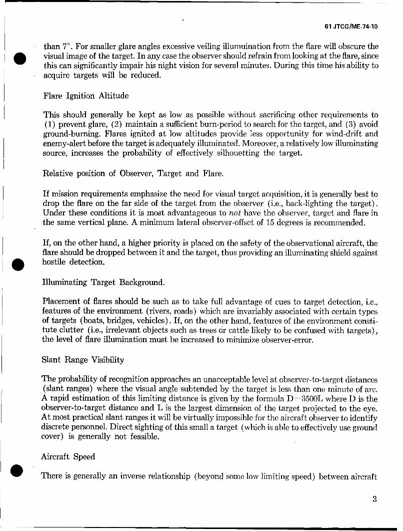
Here the flare is mounted and burned either face-up or face-down in a manner to facilitatesmoke removal. Recording photocells are used to measure the candle-power and burn time ofalternative candle compositions, sizes, or configurations. An application of this technique isdescribed by Feagans (1967). An illustration of a flare tunnel appears in figure 3.
TOWER FACILITY
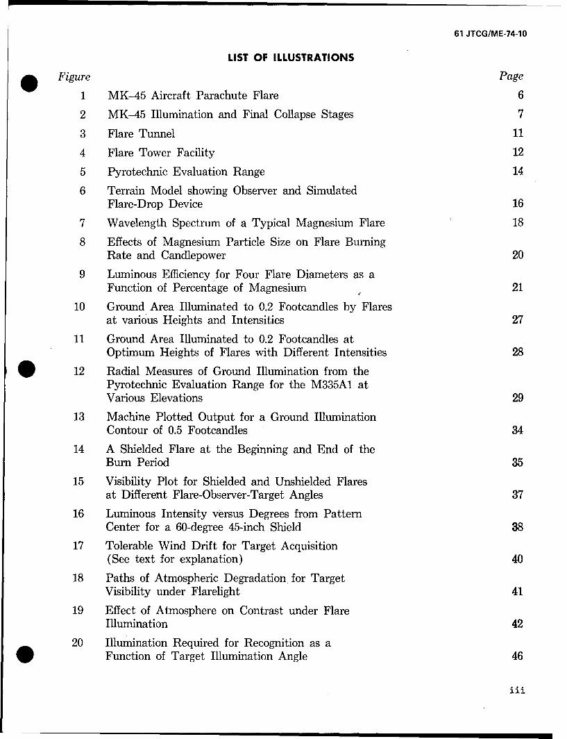
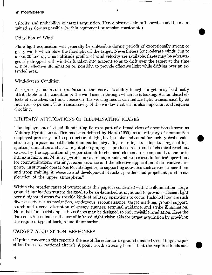
Here static tests are performed on the flare while it burns in a fixed and suspended face-downposition. Again, photocells are used to measure candle-power. In addition to the kinds of testsperformed in the flare tunnel, ground illumination can be directly measured here at variousmultiaspect angles. This method has been described by Stoval (1966) and is illustrated infigure 4.
FIELD TEST
In this type of test flares are deployed over test ranges under simulated and relatively con-trolled operational conditions; i.e., using appropriate launch and/or observational aircraft,tactical maneuvers, drop altitudes, deployment of targets, etc. Within the general categoryof field tests the following alternative techniques are being used.
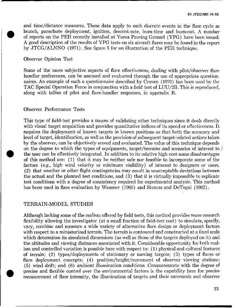
Pyrotechnic Evaluation Range (PER)
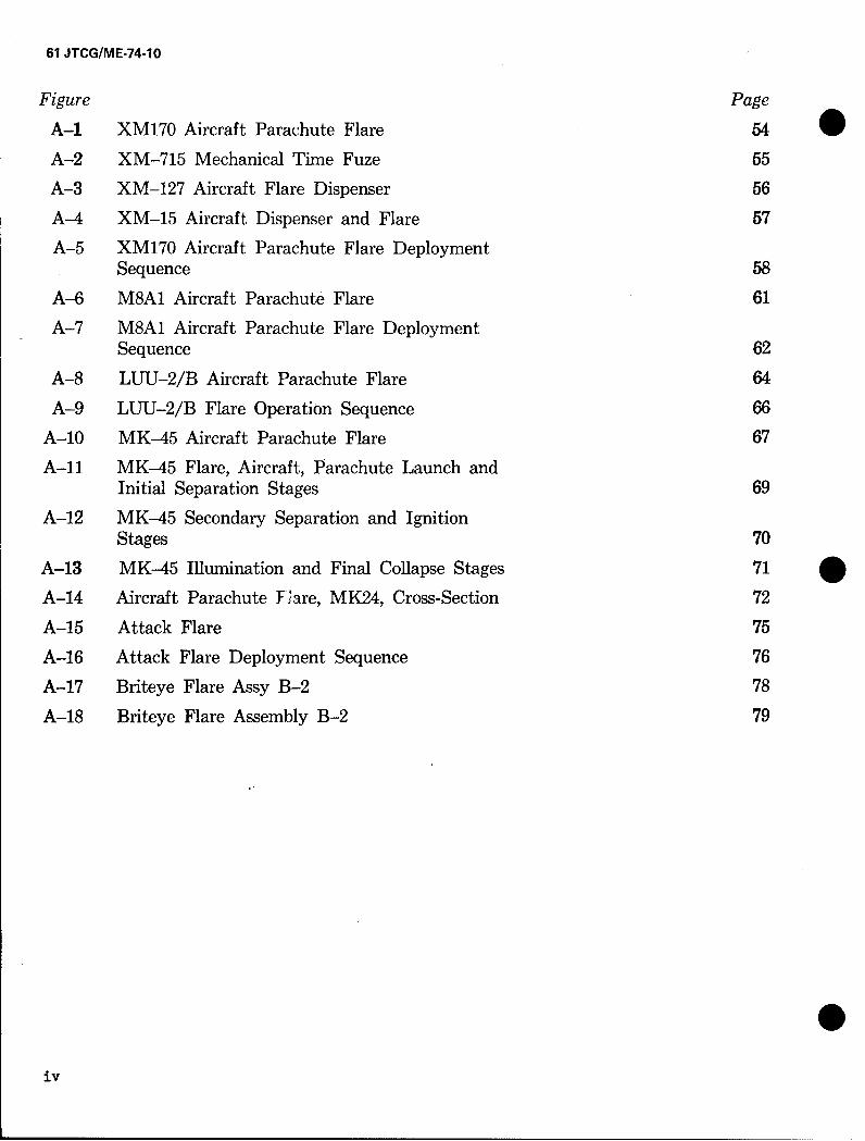
This technique described by Brooks (1970) utilizes a spaced matrix of photo sensors placedon the ground at fixed separations. The sensitivity of each sensor is adjusted so that it canbe triggered by a required amount of illumination (usually some fraction of a footcandle).The pattern of response for the entire sensor matrix (covering a ground area of 8100 ft sq)can be observed and recorded by means of a remote real-time electro-optical display. Determi-nation of flare candle-power can also be made by conventional detectors, analogue or by a so-called peripheral technique utilizing the "on" cells at the periphery of the illuminated area[JTCG/ALNO (1971)]. The PER technique has permitted a reliable real-time, photometricintercomparison of ground illumination patterns registered by operational or developmentalflares as a function of such factors as altitude, wind-drift, burn-time, or rate of descent.Useful supplementary data are also recorded from observer stations in the form of judgments
10
61 JTCG/ME-74-1O
ww
* IAJ
wLL CY
zz
C131
61 JTCG/ME-74-10
0
PHOTOCELL
126 FT PCTOWER -
/as 900
PC*C* PC PCFLARE
50 ET
PHOTOCELL
0 INSTRUMENTATION
PC TRUCK
Figure 4. Flare Tower Facility
112
61 JTCG/ME-74-10
and time/distance measures. These data apply to such discrete events in the flare cycle aslaunch, parachute deployment, ignition, descent-rate, burn-time and burn-out. A numberof reports on the PER recently installed at Yuma Proving Ground (YPG) have been issued.A good description of the results of YPG tests on six aircraft flares may be found in the reportby JTCG/ALNNO (1971). See figure 5 for an illustration of the PER technique.
Observer Opinion Test
Some of the more subjective aspects of flare effectiveness, dealing with pilot/observer flarehandler preferences, can be assessed and evaluated through the use of appropriate question-naires. An example of such a questionnaire described by Craven (1970) has been used by theTAC Special Operation Force in conjunction with a field test of LUU/2B. This is reproduced,along with tallies of pilot and flare-handler responses, in appendix B.
Observer Performance Tests
This type of field-test provides a means of validating other techniques since it deals directlywith visual target acquisition and provides quantitative indices of its speed or effectiveness. Itrequires the deployment of known targets in known positions so that both the accuracy andlevel of target, identification, as well as the precision of subsequent target-related actions takenby the observer, can be objectively scored and evaluated. The value of this technique dependson the degree to which the types of equipments, target/terrains and scenarios of interest to/the user can be effectively integrated. In addition to its relative high cost some disadvantagesof this method are: (1) that it may be neither safe nor feasible to incorporate some of thefactors (e.g., high wind velocity or minimum visibility) of interest to designers or users,(2) that weather or other flight contingencies may result in unacceptable deviations betweenthe actual and the planned test conditions, and (3) that it is virtually impossible to replicatetest conditions with a degree of consistency required for experimental analysis. This methodhas been used in flare evaluation by Weasner (1965) and Strauss and DeTogni (1962).
TERRAIN-MODEL STUDIES
Although lacking some of the realism offered by field tests, this method provides more researchflexibility allowing the investigator (at a small fraction of field-test cost) to simulate, specify,vary, combine and measure a wide variety of alternative flare design or deployment factorswith respect to a miniaturized terrain. The terrain is contoured and constructed at a fixed scalewhich determines its simulated dimensions (as well as those of the targets deployed on it) andthe altitudes and viewing distances associated with it. Considerable opportunity for both real-ism and controlled variation is possible here with respect to: (1) physical and cultural featuresof terrain; (2) types/deployments of stationary or moving targets; (3) types of flares orflare deployment concepts; (4) position/height/movement of observer viewing stations;(5) wind drift; and (6) ambient illumination conditions. Commensurate with the degree ofprecise and flexible control over the environmental factors is the capability here for precisemeasurement of flare intensity, the illumination of targets and their surrounds and observer
13
61 JTCG/ME-74-1O
C04-RO SPLAGYG
PANEL
Figure 5. Pyrotechnic Evaluation Range
14
61 JTCG/ME-74-10
response. However, a strong possibility exists with this method for over-simplification and* artificiality in incorporating real-world factors. Moreover, there are current state-of-the-art
limitations in adequately simulating and measuring certain variables, such as smoke, at-mospheric aerosols, or observer stress.
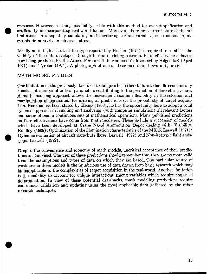
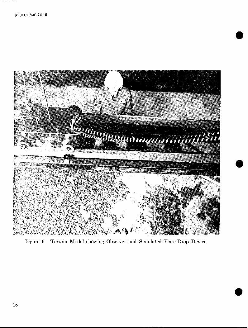
Ideally an in-flight check of the type reported by Hucker (1972) is required to establish thevalidity of the data developed through terrain modeling research. Flare effectiveness data isnow being produced for the Armed Forces with terrain models described by Hilgendorf (April1971) and Tyroler (1971). A photograph of one of these models is shown in figure 6.
MATH-MODEL STUDIES
One limitation of the previously described techniques lie in their failure to handle economicallya sufficient number of critical parameters contributing to the prediction of flare effectiveness.A math modeling approach allows the researcher maximum flexibility in the selection andmanipulation of parameters for arriving at predictions on the probability of target acquisi-
tion. Here, as has been stated by Kemp (1968), he has the opportunity here to adopt a totalsystems approach in handling and analyzing (with computer simulation) all relevant factorsand assumptions in continuous sets of mathematical operations. Many published predictionson flare effectiveness have come from math modelers. These include a succession of modelswhich have been developed at Crane Naval Ammunition Depot dealing with: Visibility,Bradley (1969); Optimization of the illumination characteristics of the MK45, Laswell (1971);
* Dynamic evaluation of aircraft parachute flares, Laswell (1972) and Non-isotropic light emis-W ions, Laswell (1972).
Despite the convenience and economy of math models, uncritical acceptance of their predic-tions is ill-advised. The user of those predictions should remember that they are no more validthan the assumptions and types of data on which they are based. One particular source ofweakness in these models is the injudicious use of data drawn from basic research which maybpU' iapplicable to the complexities of target acquisition in the real-world. Another limitationis the inability to account for unique Interactions among variables which require empiricaldtermnation. In view of theso potential drawbacks, math modeling predictions require
continuous validation •nd updating using the most applicable data gathered by the otherresearch techniques.
015
61 ITCG/ME-74-10
400
~77
I,,4,
Figure 6. Terrain Model showing Observer and Simulated Flare-Drop Device
16
61 JTCG/ME-74-10
SECTION III
* FLARE EFFECTIVENESS FACTORS
Having provided a background for the types of research methodology on which flare effective-ness is based, relevant data from recent studies will now be reviewed. Results and recom-mendations will be discussed within the context of factors associated with: (a) Candle Com-position; (b) Flare Deployment; (c) Wind drift; (d) Atmosphere; (e) Target/Backgroundcharacteristics; and (f) Observer Position.
CANDLE COMPOSITION
The source of the flare system is the burning candle which, depending on its composition,emits wavelengths of varying intensities from both the visible and invisible regions of the spec-trum. Pyrotechnic light sources can be represented in terms of selective radiation by thermallyexcited molecules superimposed on the radiation of solids and liquids in flame. By appropri-ately selecting the materials used in compounding the flare candle, it is possible to controlthe spectral regions at which this emission occurs, thus producing red, yellow, green, blue orwhite radiation. Ellern (1968) gives typical formulations for each color of flame. For illumi-nation flares, however, an effective spectral distribution is one approximating sunlight. Thisis presently best obtained from a composition expressed in percentages of magnesium (inpowdered form), sodium nitrate and a binder. A flame of high luminosity is provided byselective" radiation from the sodium which broadens into a continuum over the visible range
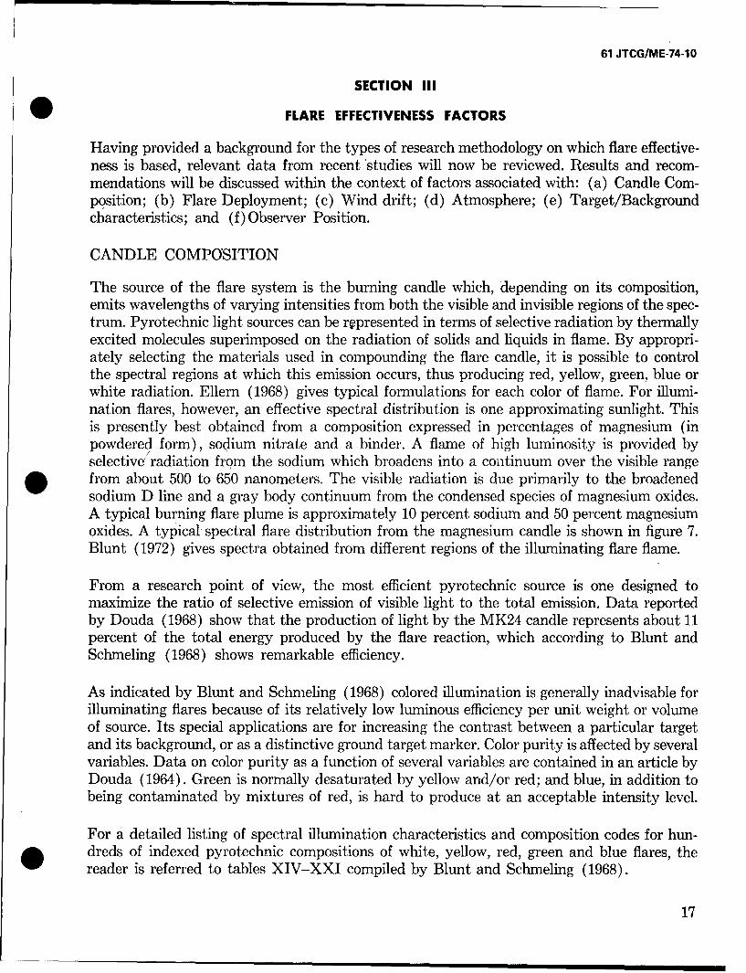
* from about 500 to 650 nanometers. The visible radiation is due primarily to the broadenedsodium D line and a gray body continuum from the condensed species of magnesium oxides.A typical burning flare plume is approximately 10 percent sodium and 50 percent magnesiumoxides. A typical spectral flare distribution from the magnesium candle is shown in figure 7.Blunt (1972) gives spectra obtained from different regions of the illuminating flare flame.
From a research point of view, the most efficient pyrotechnic source is one designed tomaximize the ratio of selective emission of visible light to the total emission. Data reportedby Douda (1968) show that the production of light by the MK24 candle represents about 11percent of the total energy produced by the flare reaction, which according to Blunt andSchmeling (1968) shows remarkable efficiency.
As indicated by Blunt and Schmeling (1968) colored illumination is generally inadvisable forilluminating flares because of its relatively low luminous efficiency per unit weight or volumeof source. Its special applications are for increasing the contrast between a particular targetand its background, or as a distinctive ground target marker. Color purity is affected by severalvariables. Data on color purity as a function of several variables are contained in an article byDouda (1964). Green is normally desaturated by yellow and/or red; and blue, in addition tobeing contaminated by mixtures of red, is hard to produce at an acceptable intensity level.
For a detailed listing of spectral illumination characteristics and composition codes for hun-dreds of indexed pyrotechnic compositions of white, yellow, red, green and blue flares, thereader is referred to tables XIV-XXI compiled by Blunt and Schmeling (1968).
17
61 JTCG/ME-74-10
0
8-Ui
j70I-
0L25O-wJ 40 -
u 2C -
10-
0 400 500 600 700 BOOWAVELENGTH (NANOMETERS)
Figure 7. Wavelength Spectrum of a Typical Magnesium Flare
018
61 JTCG/ME-74-10
Within recent years a considerable amount of applied pyrotechnic research has been reportedwhich deals with the physical/chemical reactions in the plume of the burning flare. Suchstudies attempt to demonstrate and explain causal relationships between the variables asso-ciated with these reactions and the luminous efficiency of the flare candle.
Some of these studies reported by Hamrick et al. (1968) have been based on math-modelingand empirical approaches utilizing photographic, spectroscopic, x-ray and radiometric analysis.The technology required here includes such specialized areas as fluid mechanics, thermody-namics, combustion, and spectroscopy. Much of this research has relevance to the improveddesign of flare compositions. In this connection, a summary of findings and recommendationsassociated with the following variables will be presented: (1) Particle Size, (2) Amount ofMagnesium, (3) Altitude Effect, (4) Flare Diameter, (5) Flare Binder, and (6) Flare Smoke.
In the report by Hamrick et al. (1968), evaluations of these kinds of factors are made withrespect to an ideal flare which converts all of its heat of reaction into visible light emissions."Thus all factors that influence a given flare's performance and cause its amount of emittedlight to be less than that of the ideal flare contribute to the inefficiency of the flare burningprocess."
Particle Size
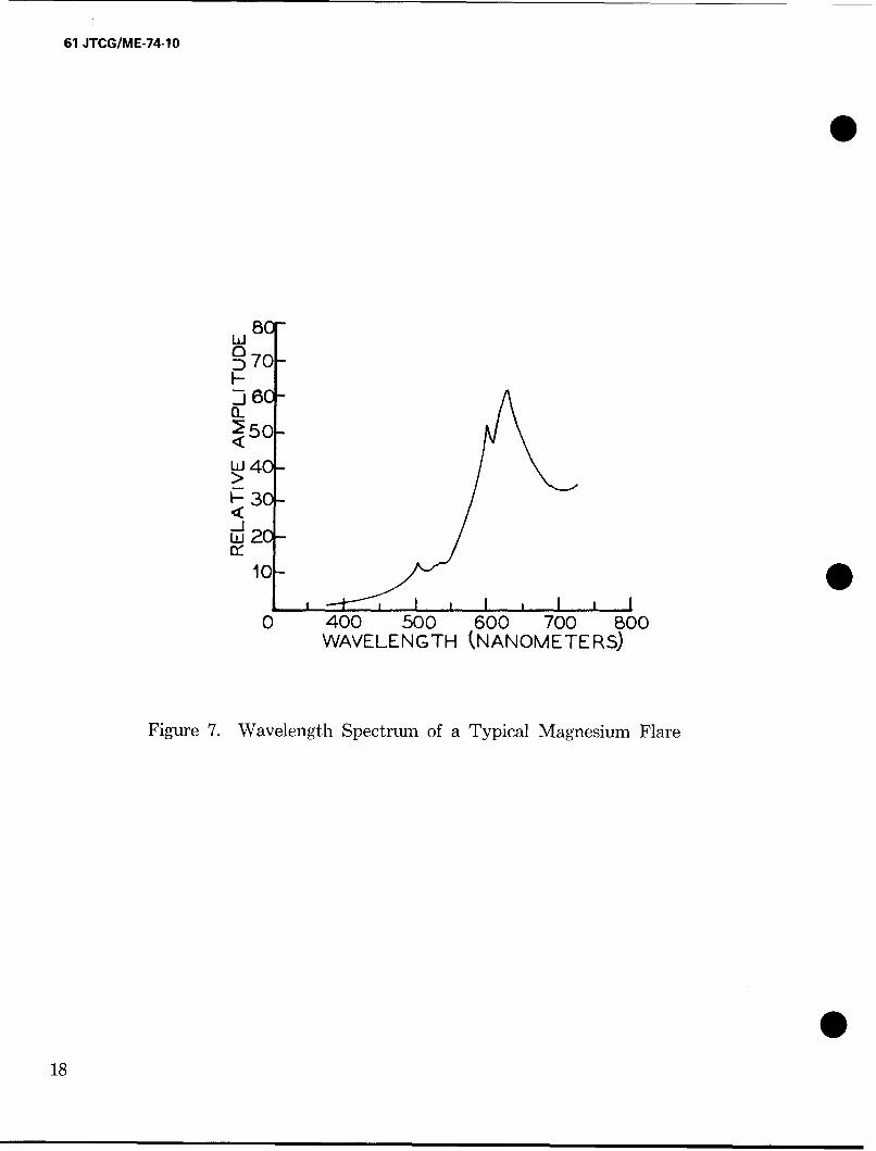
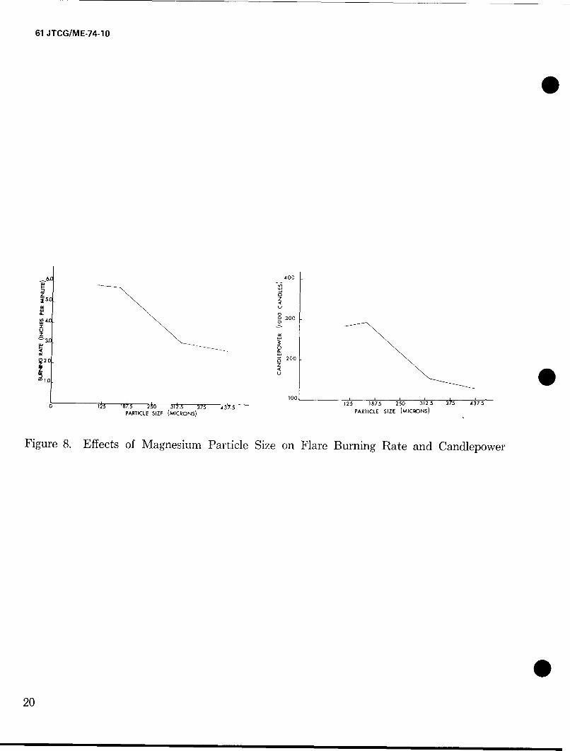
The Army Materiel Command (1967) shows, for an illuminating composition, an inverse rela-tionship for both burning rate and candlepower as a function of a particle size. Figure 8 takenfrom the AMC pamphlet shows these relationships.
Amount of Magnesium
Hamrick et al. (1968) report a drop in luminous efficiency for small (1.76 and 2.66 inchesdiameter) flares when the percentage magnesium is reduced below 62 percent. However, forlarger flares (4.25 and 7.35 inches in diameter) there is an increase in luminous efficiency fora simular reduction in magnesium content. Of the four flares tested, the greatest overall lumi-nous efficiency was shown for the one having a diameter of 4.25 inches. These data are showngraphically in figure 9. The efficiency is not only a function of the magnesium-to-sodiumnitrate ratio but also a function of the binder type. The optimum magnesium-to-sodium nitrateratio at one flare diameter may not be optimum at another diameter.
In another study by Hamrick et al. (1968), which used a scanning radiometer to analyzesmall flares of 1-inch diameter, luminous efficiency was shown to increase from 29,300 to57,400 candle-seconds per gram as the percentage 'of magnesium increased from 45 to 68.Under these conditions burn-times were shown to decrease while plume areas increased. Note,however, that this particular effect may not be extrapolated to other diameters.
Altitude Effect
Douda in NAD Crane RDTR 205 (1972) and RDTR 206 (1972) demonstrates in detail theeffect of altitude (pressure) on the intensity and spectral distribution of flare emission. With
19
61 JTCG/ME-74-10
400
Z0 z
1. C
100
0 3t 7 Y7. ,25 187.5 250 3125 375 4375
PARTICLE SIZE (MICRONS) PARTICLE SIZE (MICRONS)
Figure 8. Effects of Magnesium Particle Size on Flare Burning Rate and Candlepower
020
61 JTCG/ME-74-1O
50
u4 0 -UU)
0 30......zU
2052 56 6o0 64 6B72
0/0 MAGNESIUM
Figure 9. Luminous Efficiency for Four Flare Diameters as aFunction of Percentage of Magnesium
21
61 JTCG/ME-74-10
increasing altitude, the illuminating flare intensity is greatly reduced by the reduction in itsspectral continuum and in the broading of the sodium D lines.
Flare Diameter
Douda, (1968) has shown that the efficiency of a 30-percent magnesium pressed flare increaseswith up to 4.25 inches in flare diameter. Beyond this size, luminous efficiency rapidly decreases.In the case of cast flares, where plume size rather than flare diameter appears to be the criticalfactor, luminous efficiency levels off above a larger, 15-inch diameter. Binder levels necessaryin making these large diameter cast flares introduce another variable into this diameter experi-ment making diameter efficiency statements very difficult. The Army Materiel Command(1967) discuss relationships of flare diameter and flare efficiency for colored flares.
Flare Binder
The flare binder used to consolidate the other flare ingredients is described by Hamrick (1968)as a low viscosity liquid which polymerizes upon the addition of chemicals that cross-link thebinder molecules. A cast flare requires four times as much binder composition as a pressedflare. Binders containing fluorocarbons may be more effective because they are oxidizers.Since the luminous effectiveness of a flare has been found by Hamrick et al. (1968) to declinerapidly with increases in binder content, an optimum percentage of binder needs to be deter-mined for each flare composition. That is one that will hold the composition without degradingflare performance. Tanner (1972) has investigated the effect of binder oxygen content onadiabatic flame temperature. The most important binder variable found was the relativeamount of fuel and oxidizer el .- ients in the binder compound.
Flare Smoke
According to Johnson (1966), two types of smoke have been identified for the magnesiumflare. The first type, known as cenospheric smoke, forms the ash or fallout of a burning particleof magnesium and has no demonstrable effect on luminous efficiency. It is the second type,described as aerosol smoke, that can significantly attenuate the light output. For a downwardburning flare of 8 inches diameter with 68 percent magnesium, aerosol smoke is typically buoy-ant and will rise with minimum interference, while, in the case of 59 percent magnesium com-position, the aerosol smoke tends to hover below the flare and obscure its effectiveness. Thiseffect occurs primarily in the last portion of the burn.
FLARE DEPLOYMENT FACTORS
Given a highly efficient candle for its source, any illuminating flare system must be designedin all of its phases of deployment, (launch, ignition, suspension, descent, and burn-out) so thatthe circle of light on the ground has the required brightness, area, stability and duration topermit required types and levels of target acquisition to occur.
Therefore, a logical starting point for discussion in this section of the report will be the ground
illumination requirements for flares. Relevant data on the following topics will then be re-
22
61 JTCG/ME-74-10
viewed: altitude, bum-rate, rate of descent, flicker, candle orientation, multiple launch andflare shielding,
Ground Illumination Requirements
a. Intensity. Since the effectiveness of ground luminance is so dependent on the spectralreflective properties of targets and their background, the attenuating effects of atmosphere,observer viewing distance, physiological state of the eye, type of observer task to be performed,etc., it becomes meaningless to specify any single footcandle value that would be recom-mended for all flares., Much work needs to be done within a systems context to determinespecific ground illumination requirements for a complete family of flare target acquisitiontasks. Present illumination standards are somewhat arbitrary and are anchored to such groundillumination values as reported by Blunt and Schmeling (1968).
FootcandlesFull Sunlight 10,000Twilight 0.3Full Moonlight 0.1
A criteria value of 0.2 FC has been used as a threshold for the sensors on the PyrotechnicEvaluation Range at Yuma Proving Grounds.
Current operational parachute flare systems have different source intensities. These havebeen listed by the Joint Technical Coordinating Group for Air Launched Non-Nuclear Ordi-
* nance (JTCG/ALNNO) in the first row of table 1.
Using a terrain model approach, Ililgendorf (1969) has simulated flare drops of two ofthese systems (MX24 and B3riteye) over 1I-1000 scale model and shown significant targetacquisition advantages (measured in terms of observer accuracy and response speeds) for thebrighter MLU-32 system. Despite this apparent advantage, an upper limit of optimal flareintensity may have been exceeded in the Briteye since observers complained of excessive glarefrom the simulated five million candlepower source.
b. Color. No studies on this factor have been reported for illumination flare systems. As pre-viously indicated, candles producing color are less efficient than standard illumination flares.Nevertheless, in certain cases, advantages may accrue to the deployment of colored flareswhich have spectra-zonal illuminating characteristics designed to enhance visible contrastfor particular target/background combinations.
c. Area. Increasing the area of effective light on the ground may be dictated either by militaryrequirements for wider combat zone coverage or by the observer's need for contextual cuesto gupport his identifications, Research aimed at both these requirements is needed whichshows relationships between extents of lighted areas and target acquisition measures.
d. Stability. Flares, not only produce noticeable flicker as they burn, but also cast movingshadows on the ground as they oscillate and drift with the wind. Again, we have little datato Indicate the degree to which target acquisition is affected by these kinds of temporal/
23
61 JTCG/ME-74-1O
o 00 mLo rl 0 co
Clý
Nr *q Cý 10 0 9 0m
-4 C
0 co CEO,,
-4 o6 t--
cq Lrý LO 0
I-
C-7 m
C, r. 0 0
U.
0)
(D Nt o c:> N)C- 0 oc
z oC.LOC~- 60 L
N~ Np (
oo N'l m cL6 6 6 <
11 - 0 4-
C) -o) 0 .bfl - ~ E
4- 0
0~~U 0.' 4
.) bi) U :t >~
24
61 JTCG/ME-74-10
spatial changes in light patterns. Until such determinations are made, one can hardly justifythe cost of redesigning flares to eliminate flicker and drift.
One study soon to be published by Tyroler and Davis employs the terrain model (scaled at160:1) located at Picatinny Arsenal. Here they have examined the effect of flicker on targetrecognition. This work measures target recognition illumination requirements at selectedfrequencies from 1 to 25 Hz and also non-flicker conditions. Initial results of this experimentindicate that the lower frequencies approximately 3-10 Hz require more illumination fortarget recognition than do the higher frequencies of approximately 12-25 Hz. The higherfrequencies differ little from the no flicker conditions in the illumination required for targetrecognition.
e. Duration. Like area, time is a factor in flare ihumination, and is, in turn, dependent onboth operational and observer requirements. Over-extended exposure may be tacticallydisadvantageous (unnecessarily warning the enemy or revealing friendly forces on theground), while too brief an interval of light may not afford the observer enough search-timeto carry out his assigned task. This problem of exposure duration arises in connection with thedesign, suggested by Tyroler (1971), of rapid burning flares which emit brighter light forshorter periods of time. Research is needed to determine best intensity/time tradeoffs forflare-light to enable an observer to perform effectively in tactical situations.
Flare Altitude
A basic point of departure in planning a flare launch cycle is consideration of the altitudeS range over which the flare is effective. In particular a single altitude exists (and can be deter-
mined) for any flare where a maximum area can be illuminated to a predetermined level.This so-called "optimal height" of a burning flare can be derived from basic illuminationtheory andin the simplest case, is based on the following assumptions:
a. That the flare represents a point source of illumination having known candlepower (I)and altitude (h).
b. That the ground is essentially a plane surface, either normal to the path of light from theflare, or at some known angular inclination from it.
c. That the wind velocity is zero and light transmission through the atmosphere is 100 percent.
Given the above assumptions, along with specific values representing flare intensity and groundillumination requirements, Cohen and Kottler (1954) have applied the inverse square law of
light (E = -L-2) to calculate:
(1) The optimum height (h opt) of the flare for a desired radius (Ro) to be illuminated ata specified level of footcandles (E):
h opt = 0.71 Ro
If an average ground inclination of 45 degrees is assumed, the equation becomes:0 h opt = 0.28 Ro
25
61 JTCG/ME-74-10
(2) The required minimum flare candlepower (I) for a desired radius (Ro) with the desiredfootcandles (E) at the periphery.
I = 2.58 E Ro'
For an average ground inclination of 45 degrees the equation becomes:I = 1.24 E Ro'
(3) The optimum height of a flare (h opt) which will provide a specified illumination (E) inFC on the ground with a specified candlepower (I):
h opt = 0.438 I/E
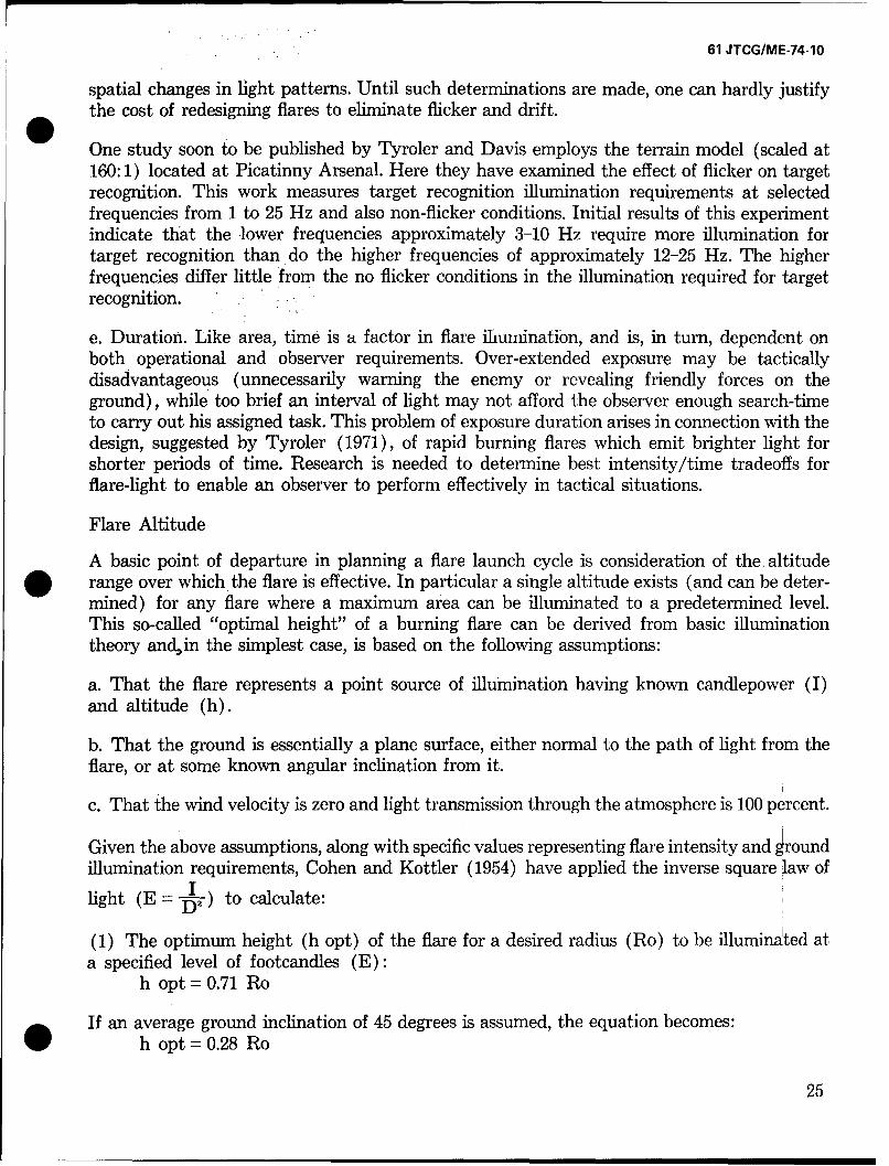
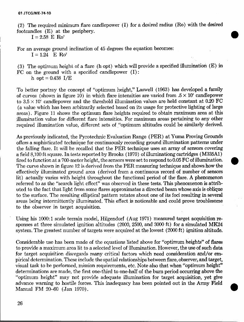
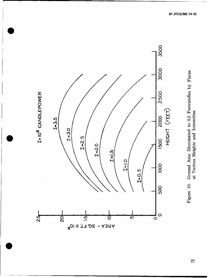
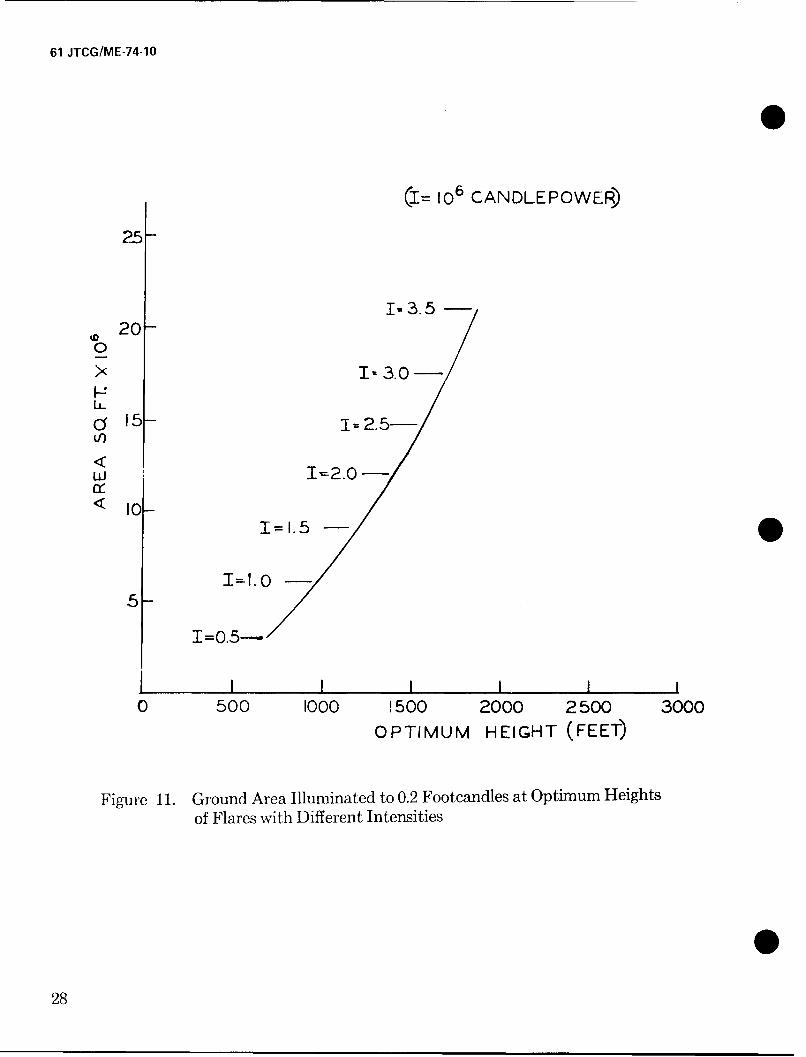
To better portray the concept of "optimum height," Laswell (1963) has developed a familyof curves (shown in figure 10) in which flare intensities are varied from .5 X 10' candlepowerto 3.5 X 10' candlepower and the threshold illumination values are held constant at 0.20 FC(a value which has been arbitrarily selected based on its usage for protective lighting of largeareas). Figure 11 shows the optimum flare heights required to obtain maximum area at thisillumination value for different flare intensities. For maximum areas pertaining to any otherrequired illumination value, different sets of "optimum altitudes could be similarly derived.
As previously indicated, the Pyrotechnic Evaluation Range (PER) at Yuma Proving Groundsoffers a sophisticated technique for continuously recording ground illumination patterns underthe falling flare. It will be recalled that the PER technique uses an array of sensors coveringa field 8,100 ft square. In tests reported by Brooks (1970) of illuminationg cartridges (M335A1)fired to function at a 700-meter height, the sensors were set to respond to 0.05 FC of illumination.The curve shown in figure 12 is derived from the PER measuring technique and shows how theeffectively illuminated ground area (derived from a continuous record of number of sensorslit) actually varies with height throughout the functional period of the-flare. A phenomenonreferred to as the "search light effect" was observed in these tests. This phenomenon is attrib-uted to the fact that light from some flares approximates a directed beam whose axis is obliqueto the surface. The resulting elliptical pattern rotates about one of its foci resulting in severalareas being intermittently illuminated. This effect is noticeable and could prove troublesometo the observer in target acquisition.
Using his 1000:1 scale terrain model, Hilgendorf (Aug 1971) measured target acquisition re-sponses at three simulated ignition altitudes (2000, 2500, and 3000 ft) for a simulated MK24system. The greatest number of targets were acquired at the lowest (2000 ft) ignition altitude.
Considerable use has been made of the equations listed above for "optimum heights" of flaresto provide a maximum area lit to a selected level of illumination. However, the use of such datafor target acquisition disregards many critical factors which need consideration and/or em-pirical determination. These include the spatial relationships between flare, observer, and target,visual task to be performed, mission requirements, etc. Note also that when "optimum height"determinations are made, the first one-third to one-half of the burn period occurring above the"optimum height" may not provide adequate illumination for target acquisition, yet giveadvance warning to hostile forces. This inadequacy has been pointed out in the Army FieldManual FM 20-60 (Jan 1970). 0
26
61 JTCG/ME-74-1O
000
00)
0
0)
0 40
CLC
00 LUJto 0 L
NH F-
o Idto 0
0H
Q)j
H O 0II 0
00
H
86
LO0 LO 0o'
9 O01X:L.O -V3ýJV
27
61 JTCG/ME-74-10
(I= 106 CANDLEPOWER)
25-
1-3.5 -
'D20-
0
X I-3.0o
0•15 1=2.5-5
< I
w T2.0-/
~i1 1. 5 -
=1.0-
I=0.5-
I I I II0 500 1o0o 1500 2000 2500 3000
OPTIMUM HEIGHT (FEET)
Figure 11. Ground Area Illuminated to 0.2 Footcandles at Optimum Heightsof Flares with Different Intensities
028
61 JTCG/ME-74-10
4jLO)
0*
.0
2.5
0
U)
o
ný 2.50-
O
000
1.0-
4
cc
.5
00 500 1000 1500 2000 2500 3000
ELEVATION (FEET)
Figure 12. Radial Measures of Ground Illumination from the Pyrotechnic Evaluation Rangefor the M335AI at Various Elevations
29
61 JTCG/ME-74-10
Burn-Rate
Associated with the composition of the flare is the rate at which it burns. Moreover, there is areciprocal relationship between burn-time and intensity, i.e., halving the bum-time approxi-mately doubles the intensity of a flare. Tyroler, in an unpublished article (1971), is concernedwith four contingencies related to burn-time which are clearly important in any estimate offlare system effectiveness:
a. The amount of area adequately illuminated.
b. The total time during which the area is so illuminated.
c. The alerting of enemy personnel in the target area prior to adequate illumination.
d. The probability of the illuminated area remaining in the desired location.
Given all these considerations Tyroler suggests that the design of a new flare of equal size butfaster burn-time, might increase effectiveness; moreover, he feels that such a design might bestbe achieved by the incorporation of successive stages of decreasing burn-time (incrementalconcept). Such a modification could provide a larger ground area of adequate illumination andmaintain this illumination during the early period of flare ignition. The likelihood of prema-turely warning an enemy would also be diminished and the probability of prevailing windsblowing the flare off-target prior to the establishment of adequate illumination would bedecreased.
Rate of Descent
Another factor controlling the effectiveness of a flare is its rate of descent. Other things beingequal, the most effective use of a flare would be to hold it stationary at the optimum altitudeover the target during the entire burn-period. Barring the feasibility of this condition, the nextbest recommendation is to slow the flare's descent-rate. However, this requires enlarging thesize of the parachute, thus increasing both cost and weight of the total flare package. In fact,Laswell (1963) states that the cost of cutting the descent rate by one-half raises the total costof flare deployment six times. In any case, an appreciable drop-rate of at least two to threefeet per second (FPS) is required to remove light-attenuating smoke from the flare. Also, tooslow a descent will increase susceptibility to wind drift. Average drop-rates for current opera-tional systems evaluated by JTCG/ALNNO (1971) vary from 6.4 FPS for the MK24 to8.5 FPS for the M8A. One should also note that these rates are not constant throughout thedescent period but decrease as the burning flare loses mass and generates heat.
Flare Orientation
Flare illumination can also be affected by the orientation of the burning candle, i.e., whetherit is suspended in its typical face-down position, or whether its orientation is altered so that itdescends in either a horizontal or a face-up position. In a tunnel test Feagans (1967) comparedthe intensities of multiple flares burned side-by-side either in a perpendicular or parallel align-
30
61 JTCG/ME-74-10
ment with the plane of the detector. The first arrangement represented "burning across afront" and resulted in a four-fold increase in candle power for four flares oriented in thisposition. The second arrangement represents "burning in depth" and resulted in no appreciableincrease in intensity with increments up to four flares. In an expansion of this kind of research,Wildridge (1966) checked out various single or multiple flare systems capable of producing'five million candle power for a 5-minute burn-time. Both static tests from tower facilities andflight tests were run. Two basic orientations were studied; multiple candles burning facedownward and multiple candles burning horizontally. The horizontal method of suspensionwas found in general to provide illumination equivalent to the vertical system and had thefollowing specific advantages: (1) the possibility of cleaner smoke removal, (2) more uniformillumination patterns, and (3) elimination of heat arising around the candle (which couldburn parachute suspension cables). The main disadvantage here was the increased cost andpay-load requirement for a spreader mechanism to suspend the flares in a horizontal position.
Multiple Flare Systems
Conventional single flare systems are so limited with respect to the intensity, area, and durationof the ground illumination they can provide that many military applications require the useof multiple flare systems. One type of multiple deployment would be to release several flaressimultaneously, these either being suspended from a single parachute system or from individualchutes. Aside from payload cost, two or more flares dropping from a single chute can causeproblems such as over-rapid rates of descent or excessive oscillation. If the heat and smoke ofa heavy flare system could be effectively utilized, the rates of descent might, however, bedecreased to tolerable limits.
With simultaneous multiple-chute deployment Wildridge (1966) states that mutual inter-ference is likely to occur. The smoke of faster-falling flares may attenuate the light of a slowerone, or the candle of one flare may burn the shroud lines of another. Wildridge also refers toanother malfunction of multi-chute systems known as "squidding" whereby the system reachesa velocity below the opening velocity of one of the parachutes causing it to dump.
An alternative kind of multiple-flare drop involves successive discrete deployments with appre-ciable intervals between drops. Although this sequential launching avoids the payload andinterference problems of simultaneous launch, it does introduce spatial separation of lightpatterns which would have been mutually reinforcing had they come from a single source.However, according to Blunt and Schmeling (1968) loss of ground illumination due to thisseparation will not be too severe if the distance between units in a train of flares and thecenter of their mass does not exceed ten percent of the source height. This provision can bemet even at low altitudes and high speeds with the SUU-12 system which can maintain launchintervals down to 0.10 seconds.
If the main concern, however, is lighting up an extensive area rather than approximating asingle source, then much larger inter-flare distances can be used. If the area is to be a long
* narrow path, Blunt and Schmeling (1968) offer a formula for computing the ground illumi-nance in foot candles of a point beneath a numbered string of flares of known height, candle
31
61 JTCG/ME-74-10
power, and separation. Using their mode of analysis the illuminance of a point (Ep) in thecenter of a seven-flare string is shown to be 4.12 I/h2 (where I = candle power and h = altitude).This formula reveals a principle of diminishing returns whereby increasing the flare number Sby 30 percent (from 7 to 9) would only increase the brightness coefficient by 7.5 percent (from4.12 to 4.42).
Another formula is given by Blunt and Schmeling (1968) for the case of a circular launch-patharound which flares are being deployed at regular intervals. Here, the illumination at apoint on the ground (E,) below the center of the circular path will depend on the number (n)intensity (I) and altitude (h) of the sources as well as the circumference of the flight circlewith radius (a). The formula reads:
= (h2 + a2)312
Laswell (1963) has developed a formula stating that the maximum area (A max) illuminatedto a specified level with a given intensity flare will be directly proportional to the product ofthe flare intensity and its optimum illuminating height.
A max=KIhot
Based on this expression he states that two flares with half the intensity of one large flarewould illuminate somewhat more than twice its area if they were positioned in such a mannerthat overlapping reinforcement in the respective illumination patterns is obtained. However,this type of gain is relatively small (about five percent of the maximum area) and may not becost-effective.
Starrett (1964) provides a series of analytical and numerical formulae for determining theGround Illumination Contour (GIC) which results from linear deployment of an arbitrarynumber of flares (with equal separation and at the same height and intensity). Geometriccoordinates (X,Y) for a GIC at any specified value of illumination is calculable from the fol-lowing equations derived by Starrett:
NE=hI j--M l (h2 R2 jP)-3/2
where R2j = [X+ (N - 2j + 1) d/,]Y+Y 2 .
for j = 1,2.. NE = Illumination required on the ground in footcandlesh = Flare heightI = Flare intensity in candles
Rj,= Distance (feet) from the ground point directly below flarej to the ground point P in feet.
N = Number of flaresd = Distance between flares (feet)
XY = Respective coordinates of the GIC
32
61 JTCG/ME-74-10
A value of Y is sought which will satisfy the above equations when X is fixed and N, d, E, Iand h are given.
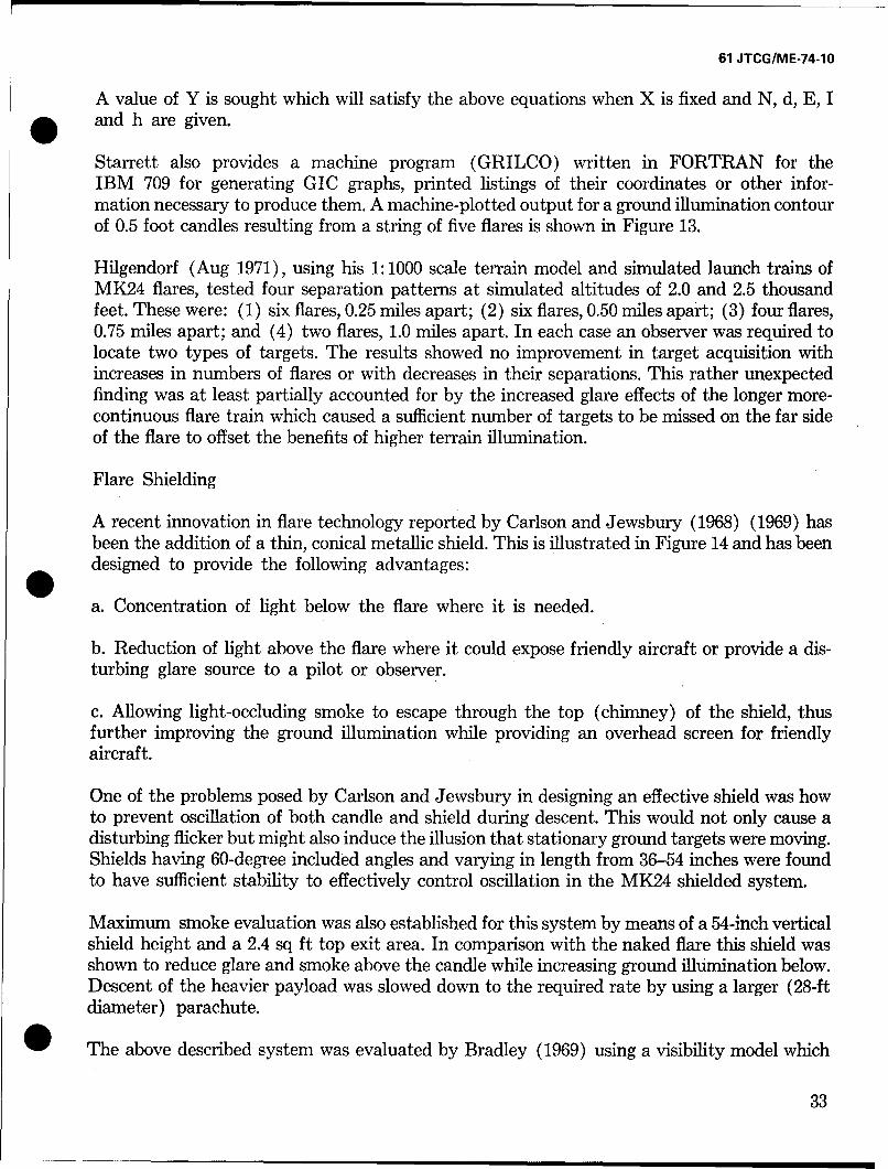
Starrett also provides a machine program (GRILCO) written in FORTRAN for theIBM 709 for generating GIC graphs, printed listings of their coordinates or other infor-mation necessary to produce them. A machine-plotted output for a ground illumination contourof 0.5 foot candles resulting from a string of five flares is shown in Figure 13.
Hilgendorf (Aug 1971), using his 1:1000 scale terrain model and simulated launch trains ofMK24 flares, tested four separation patterns at simulated altitudes of 2.0 and 2.5 thousandfeet. These were: (1) six flares, 0.25 miles apart; (2) six flares, 0.50 miles apart; (3) four flares,0.75 miles apart; and (4) two flares, 1.0 miles apart. In each case an observer was required tolocate two types of targets. The results showed no improvement in target acquisition withincreases in numbers of flares or with decreases in their separations. This rather unexpectedfinding was at least partially accounted for by the increased glare effects of the longer more-continuous flare train which caused a sufficient number of targets to be missed on the far sideof the flare to offset the benefits of higher terrain illumination.
Flare Shielding
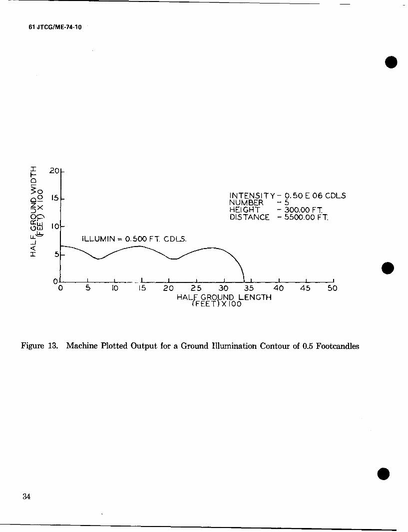
A recent innovation in flare technology reported by Carlson and Jewsbury (1968) (1969) hasbeen the addition of a thin, conical metallic shield. This is illustrated in Figure 14 and has beendesigned to provide the following advantages:
a. Concentration of light below the flare where it is needed.
b. Reduction of light above the flare where it could expose friendly aircraft or provide a dis-turbing glare source to a pilot or observer.
c. Allowing light-occluding smoke to escape through the top (chimney) of the shield, thusfurther improving the ground illumination while providing an overhead screen for friendlyaircraft.
One of the problems posed by Carlson and Jewsbury in designing an effective shield was howto prevent oscillation of both candle and shield during descent. This would not only cause adisturbing flicker but might also induce the illusion that stationary ground targets were moving.Shields having 60-degree included angles and varying in length from 36-54 inches were foundto have sufficient stability to effectively control oscillation in the MK24 shielded system.
Maximum smoke evaluation was also established for this system by means of a 54-inch verticalshield height and a 2.4 sq ft top exit area. In comparison with the naked flare this shield wasshown to reduce glare and smoke above the candle while increasing ground illumination below.Descent of the heavier payload was slowed down to the required rate by using a larger (28-ftdiameter) parachute.
The above described system was evaluated by Bradley (1969) using a visibility model which
33
61 JTCG/ME-74-10
7 20I--
c30
c__ 15 1INTEN51ITY- 0.50 E 06 CDLSNUMBER -5"D5 HEIGHT - 300.00 FTc DISTANCE - 5500.00 FT.
ILLUMIN 0.500 FT CDL5.
.. J
0 5 10 15 20 25 30 35 40 45 50HALF GROUND LENGTH
(FEET) X 100
Figure 13. Machine Plotted Output for a Ground Illumination Contour of 0.5 Footcandles
34
61 JTCG/ME-74-10
I.I
0(
Figure 14. A Shielded Flare at the Beginning and End of the Bum Period
335
61 JTCG/ME-74-10
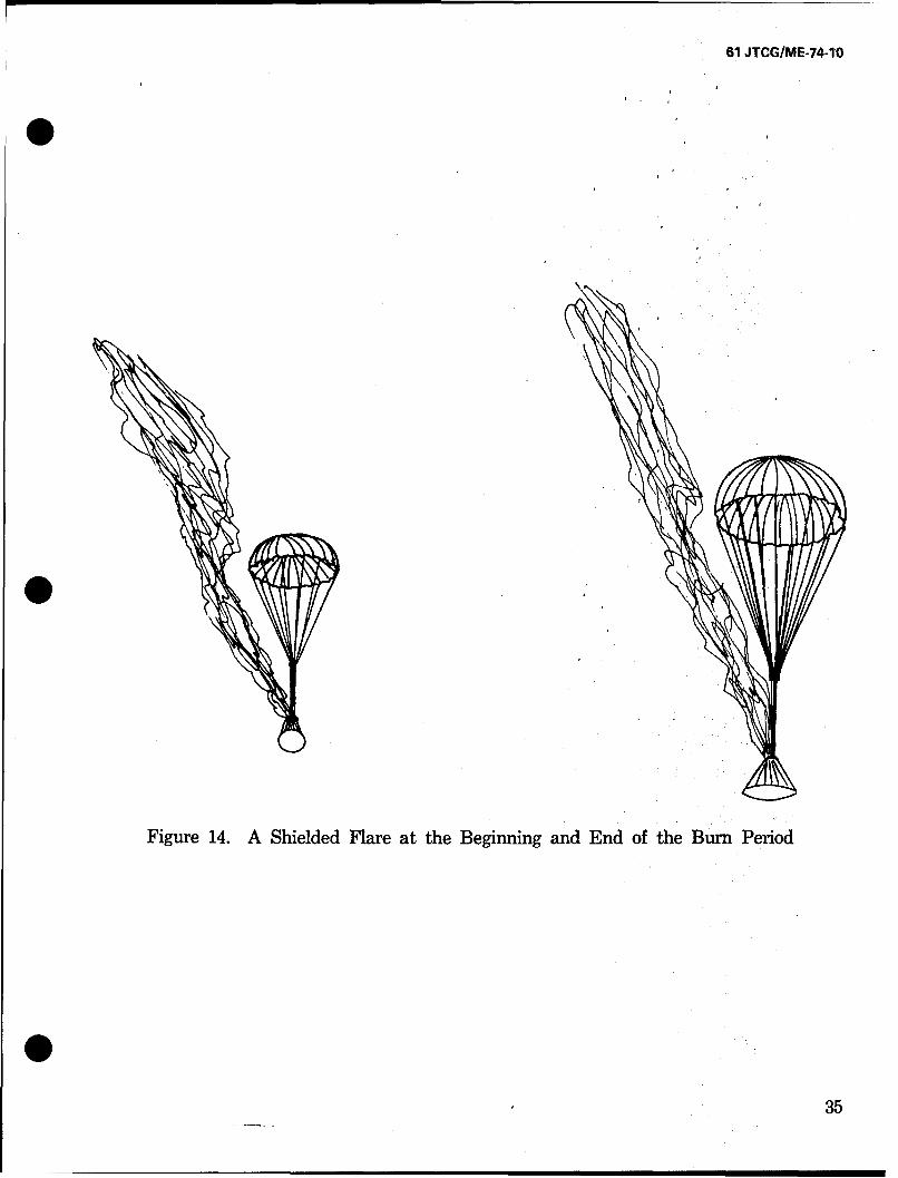
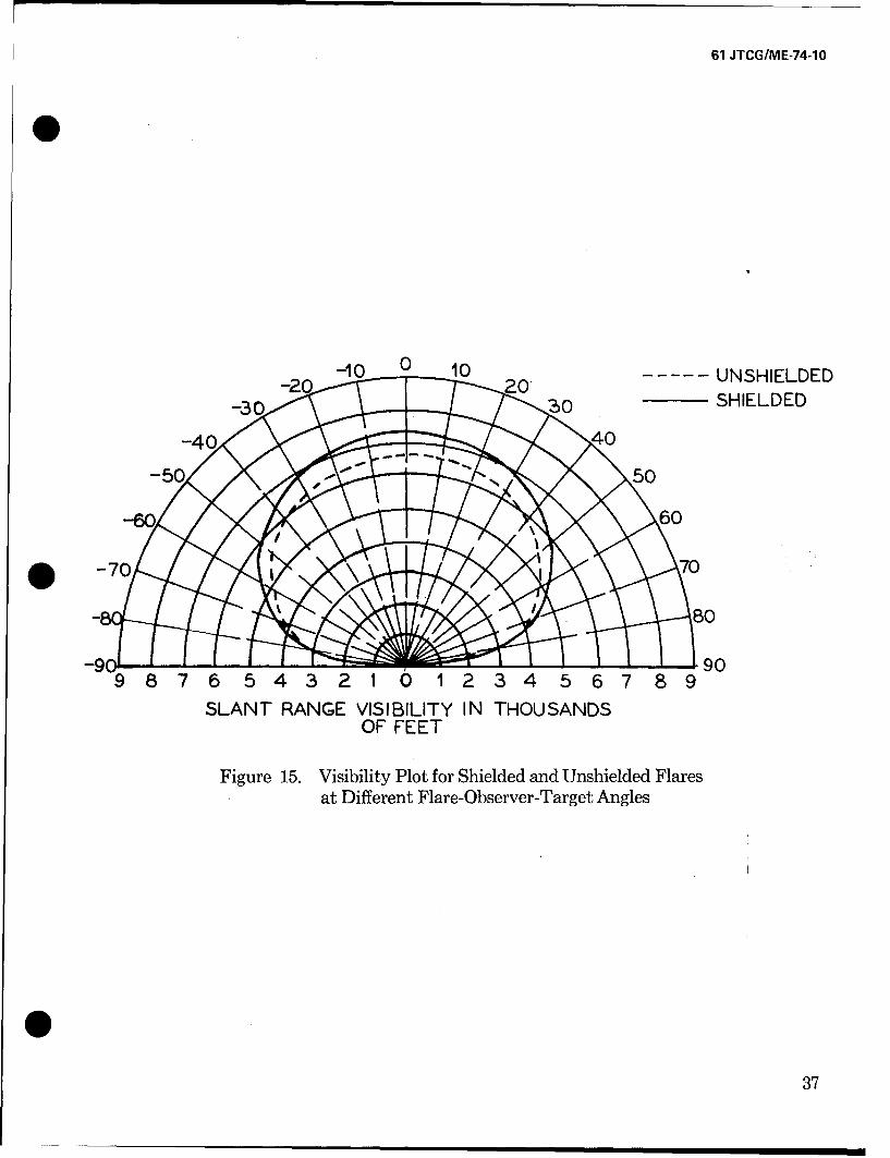
incorporated the following variables: (1) Target/background reflectivity; (2) Attenuationof light from the flare to the target, and from the target to the observer; (3) visual angularsubtense of the target; (4) Path luminance to the observer; and (5) flare glare. Series ofcomputer runs were programmed for shielded and unshielded flares at altitudes of 2600 and1500 ft. As shown in figure 15, the results indicate that glare effects (and the advantage ofshielding) increase when the angle formed between the flare, observer and target is small.
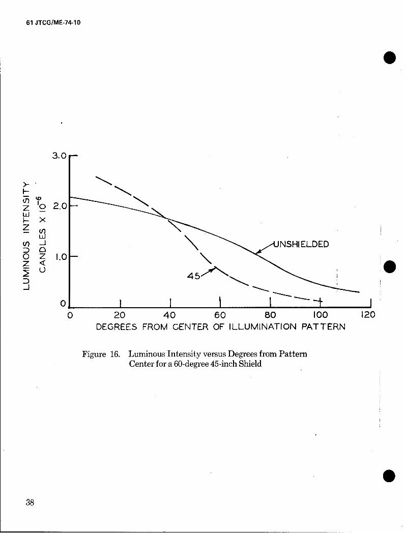
Jewsbury (1968) has measured the luminous intensity of both shielded and unshielded flaresin terms of the number of degrees from the center of their respective illumination patterns.These data are graphically portrayed in Figure 16. It can be seen that, for angles of less than 40degrees, shielded flares provide greater brightness. However, for angles greater than this value(i.e., further out from the center of illumination), unshielded flares give stronger light.
Hilgendorf (Apr 1971), again using his terrain model and simulation facility, compared theperformance of observers searching for tactical targets under conditions of both shielded andunshielded flare light. Shields were effectively simulated by modified flashlight reflectorscoated with opaque white paint. Terrain illumination for each type of flare approximated thepatterns shown in Figure 16. The results, however, did not support the efficacy of flare shieldingfor target acquisition since no significant advantages for this condition could be demonstratedwith respect to number of targets found, number of errors, or observer response time. It waspointed out that the results could have been affected by the nature of the acquisition task(wide area search for targets of opportunity) and that other potential advantages of shielding(e.g., providing obscuration of overhead aircraft) were not evaluated by this test. Nevertheless,recent field testing by the Armament Development and Test Center ('Ernst, 1972) has vali-dated Hilgendorf's finding in l-,owing no improvement in target acquisition using the shieldedflare.
WIND DRIFT
Most of the previous discussion has been based on the assumption that a flare drops perpen-dicularly from its launch point to the earth's surface. Mission planning for target acquisitionunder flare light would be greatly simplified if this were the case. However, winds of 5 to 20miles per hour are usually prevalent in the flare's environment and can easily cause thepattern of light to drift away from the intended target area. For a typical 3-minute flare onemight expect movements of more than a mile. Tyroler (1971) points out that because windsare usually gusty the flight pattern of a flare may well become unpredictable even if theaverage wind velocity is known, and that "the longer a flare burns the less likely it 'will beusefully placed for its entire burning time*"
Nevertheless, a mathematical approach for achieving effective flare utilization with nominalwind velocities by computing two circles of adequate ground illuminations (based on theinverse square principle and assumed to be 0.2 FC has been proposed. A smaller circle repre-sents the situation for the higher ignition altitude and a larger circle for the lower, bum-outaltitude. With no wind drift a continuous succession of concentric circles can be constructedto represent adequate ground illumination during the bum-time of the flare and any targetvisible within the small circle at ignition would obviously remain visible until bum-out. Wind, 036
61 JTCG/ME-74-10
--10 0 -10 2UNSHIELDED
- SHIELDED
-40 0
-60
S -70 J
9 8 7 6 5 4 3 2 1 0 1 2 3 4 5 6 7 8, 9
SLANT RANGE VISIBILITY IN THOUSANDSOF FEET
Figure 15. Visibility Plot for Shielded and Unshielded Flaresat Different Flare-Observer-Target Angles
037
61 JTCG/ME-74-10
3.0
z '02.0-
Z(,- NH IELDED
o I I •---t-0 20 40 060 80 00 120
DEGREES FROM CENTER OF ILLUMINATION PATTERN
Figure 16. Luminous Intensity versus Degrees from PatternCenter for a 60-degree 45-inch Shield
0
38
61 JTCG/ME-74-10
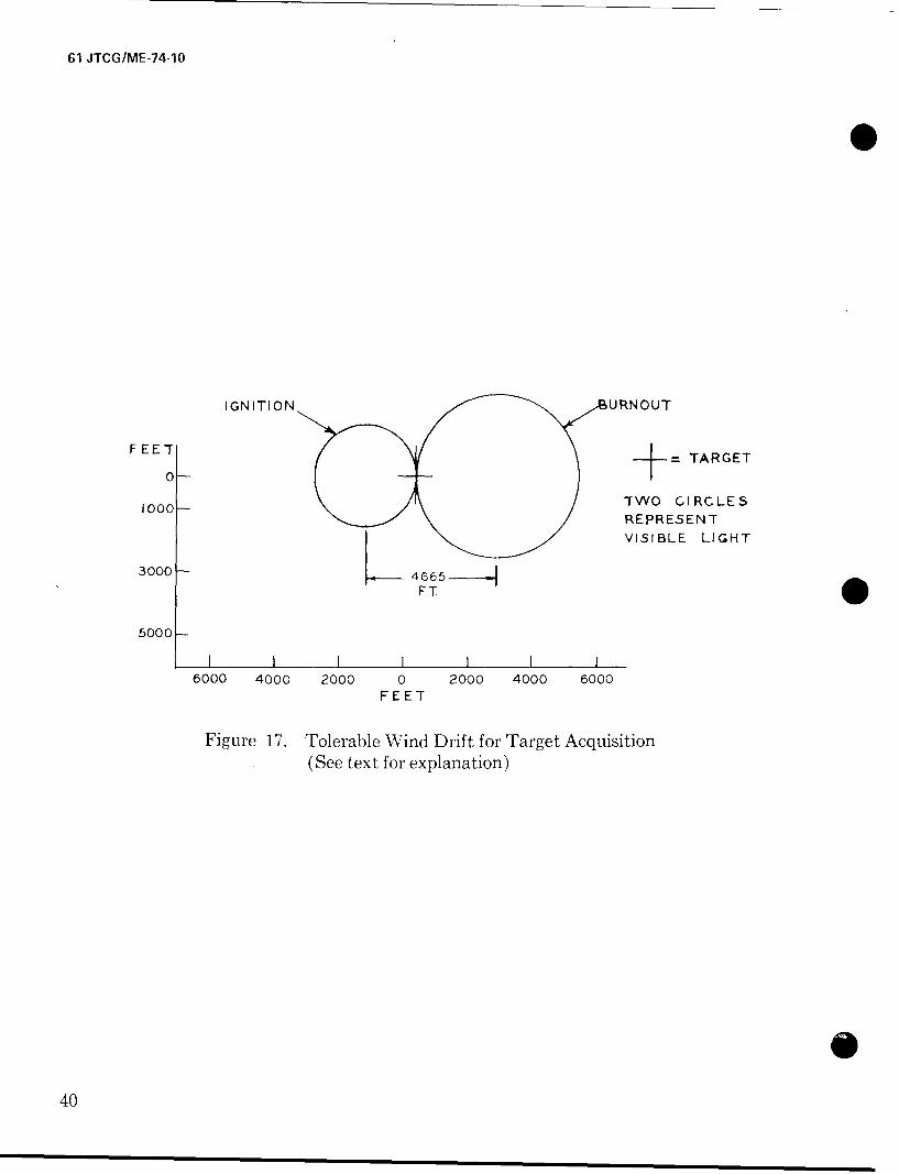
however, causes the circles to drift apart in the direction of its movement, and, given sufficientvelocity, can render initially -perceived targets invisible. The planning principle here is to soselect the type of flare (based on its ignition/bum-out altitudes, bum-time and candlepower)for a given wind velocity that: (1) there will be spatial overlap between the respective circles ofvisible light at ignition and bum-out; and (2) the target will remain in this overlapping area.
In accomplishing this set of circumstances, the planners goal would be to achieve ignition atan ideal altitude with the flare drifting directly over the target and burning out at an idealaltitude. Figure 17 provides a graphic poirtrayed of the tolerable wind drift distance for acquir-ing a target under one set of conditions.
ATMOSPHERIC EFFECTS
Just as there is almost always wind to complicate the planning of flare missions so there isan atmospheric medium which scatters and absorbs the light being transmitted from the flareto the ground, from the ground to the observer, and from the flare to the observer. Irradiationof light, as would be predicted by the inverse square law is thus reduced by a so-called ex-tinction coefficient which is less than unity and depends upon such factors as wavelength,atmospheric gases, temperature, pressure, as well as amounts of rain, fog, snow, dust andother aerosols. Visibility or meterological range refers to the horizontal distance at which at-mospheric attenuation (extinction) reduces the apparent contrast of a target to two percentof its intrinsic contrast.
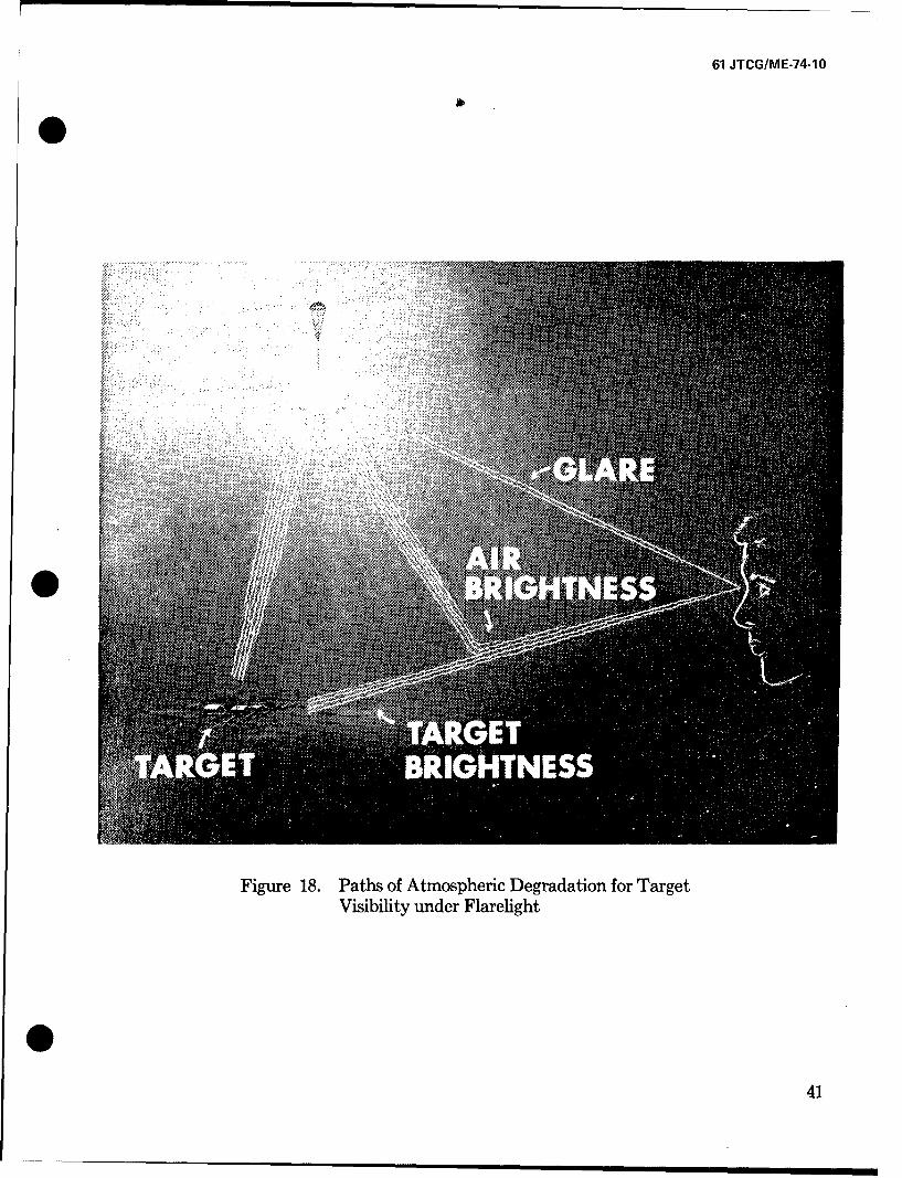
On cloudy nights under flare light conditions target visibility is subject to two kinds of atmo-spheric degradation. One of these involves light reflected from the target and attenuatedaccording to the extinction coecient. The other, referred to as path luminance, involves lightwhich is scattered by the atmosphere and added to the attenuated path of light entering theobserver's eye. The net effect of this combined attenuation and scattering is to further veil thevisibility of the target against the background. These two atmospheric effects along theobserver's line of sight are depicted in figure 18. Another visual path shown in the figure whichrepresents still further degradation comes directly to the eye from the flare which acts as aglare source.
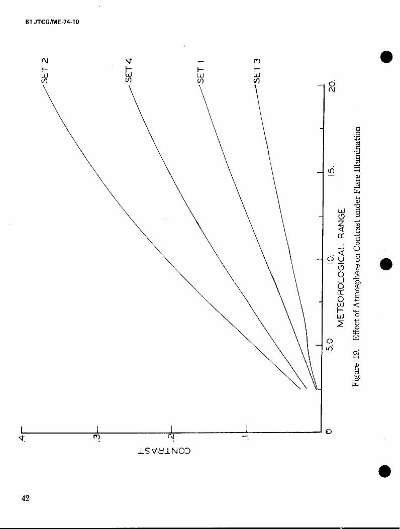
Lohkamp (1970) has constructed a mathematical model which predicts the probability oftarget detection under various conditions of atmospheric clarity, flare location and intensity,as well as pertinent characteristics of the target background. According to the author, thismodel utilizes the best available psychophysical and engineering data and is intended toaccept improved data as this becomes available. Once its validity is checked and all necessaryimprovements are made, it can provide the designers, planners, and evaluators of flare systemswith a sophisticated tool for predicting target acquisition, taking into account the effects ofsource, medium, target, background, detection and geometry as a function of time. Morerecently, Bradley and Lohkamp (1973) have analyzed the effect of atmosphere on target-background contrast under flare illumination. Their analysis of the reduction of target-to-background contrast attributable to atmospheric effects is described in figure 19. Figure 19contains four curves, each of which represents a particular geometric flare-target-observerrelationship. The specific relationships studied are given in the Bradley and Lohkamp report.
39
61 JTCG/ME-74-10
S
IGNITION UNU
IF EE = TARGET
0 +
1000- TWO CIRCLESREPRESENTVISIBLE LIGHT
3000 4665
FT
5000-
I I ii I I6000 4000 2000 0 2000 4000 6000
FEET
Figure 17. Tolerable Wind Drift for Target Acquisition
(See text for explanation)
e40
61 JTCG/ME-74-10
0
Figure 18. Paths of Atmospheric Degradation for TargetVisibility under Flarelight
441
61 JTCG/ME-74-1O
(\J rYL) 0
0L 0
CL
< 9
o~o
0L
Ltj
ISVdILNOO
42
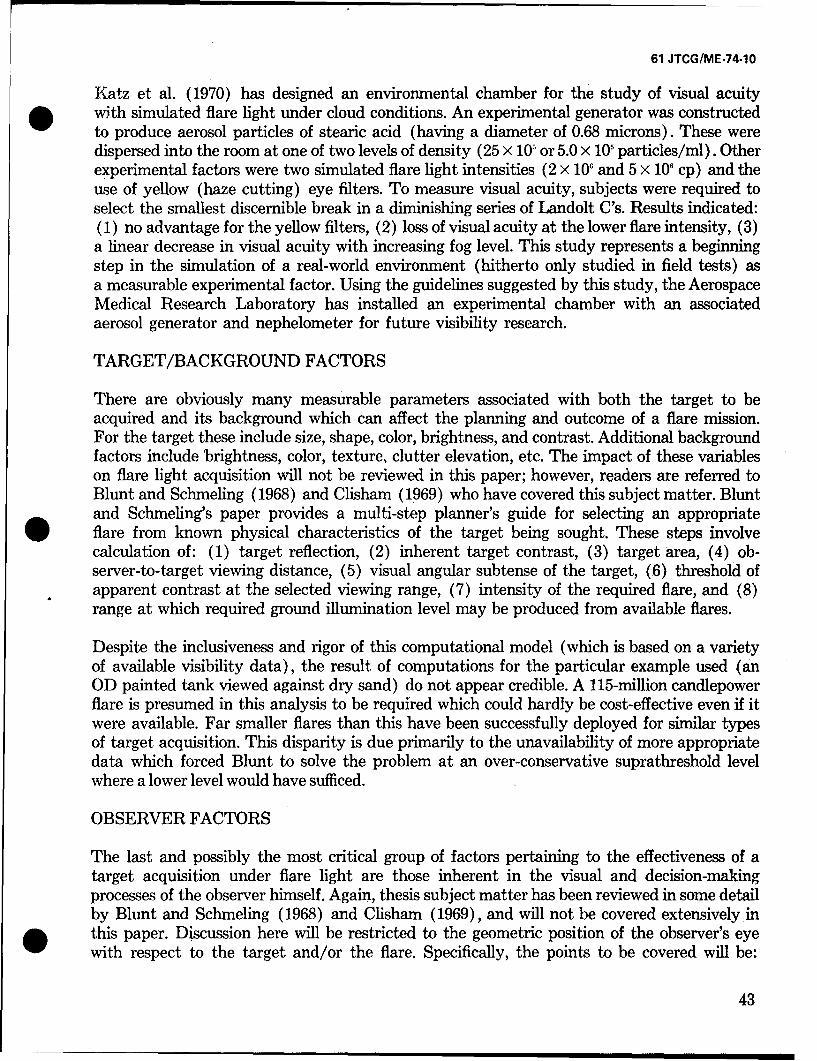
61 JTCG/ME-74-10
Katz et al. (1970) has designed an environmental chamber for the study of visual acuity* with simulated flare light under cloud conditions. An experimental generator was constructed
to produce aerosol particles of stearic acid (having a diameter of 0.68 microns). These weredispersed into the room at one of two levels of density (25 x 105 or 5.0 x 10' particles/ml). Otherexperimental factors were two simulated flare light intensities (2 x 10' and 5 x 10' cp) and theuse of yellow (haze cutting) eye filters. To measure visual acuity, subjects were required toselect the smallest discernible break in a diminishing series of Landolt C's. Results indicated:(1) no advantage for the yellow filters, (2) loss of visual acuity at the lower flare intensity, (3)a linear decrease in visual acuity with increasing fog level. This study represents a beginningstep in the simulation of a real-world environment (hitherto only studied in field tests) asa measurable experimental factor. Using the guidelines suggested by this study, the AerospaceMedical Research Laboratory has installed an experimental chamber with an associatedaerosol generator and nephelometer for future visibility research.
TARGET/BACKGROUND FACTORS
There are obviously many measurable parameters associated with both the target to beacquired and its background which can affect the planning and outcome of a flare mission.For the target these include size, shape, color, brightness, and contrast. Additional backgroundfactors include brightness, color, texture, clutter elevation, etc. The impact of these variableson flare light acquisition will not be reviewed in this paper; however, readers are referred toBlunt and Schmeling (1968) and Clisham (1969) who have covered this subject matter. Bluntand Schmeling's paper provides a multi-step planner's guide for selecting an appropriateflare from known physical characteristics of the target being sought. These steps involvecalculation of: (1) target reflection, (2) inherent target contrast, (3) target area, (4) ob-server-to-target viewing distance, (5) visual angular subtense of the target, (6) threshold ofapparent contrast at the selected viewing range, (7) intensity of the required flare, and (8)range at which required ground illumination level may be produced from available flares.
Despite the inclusiveness and rigor of this computational model (which is based on a varietyof available visibility data), the result of computations for the particular example used (anOD painted tank viewed against dry sand) do not appear credible. A 115-million candlepowerflare is presumed in this analysis to be required which could hardly be cost-effective even if itwere available. Far smaller flares than this have been successfully deployed for similar typesof target acquisition. This disparity is due primarily to the unavailability of more appropriatedata which forced Blunt to solve the problem at an over-conservative suprathreshold levelwhere a lower level would have sufficed.
OBSERVER FACTORS
The last and possibly the most critical group of factors pertaining to the effectiveness of atarget acquisition under flare light are those inherent in the visual and decision-makingprocesses of the observer himself. Again, thesis subject matter has been reviewed in some detailby Blunt and Schmeling (1968) and Clisham (1969), and will not be covered extensively inthis paper. Discussion here will be restricted to the geometric position of the observer's eyewith respect to the target and/or the flare. Specifically, the points to be covered will be:
43
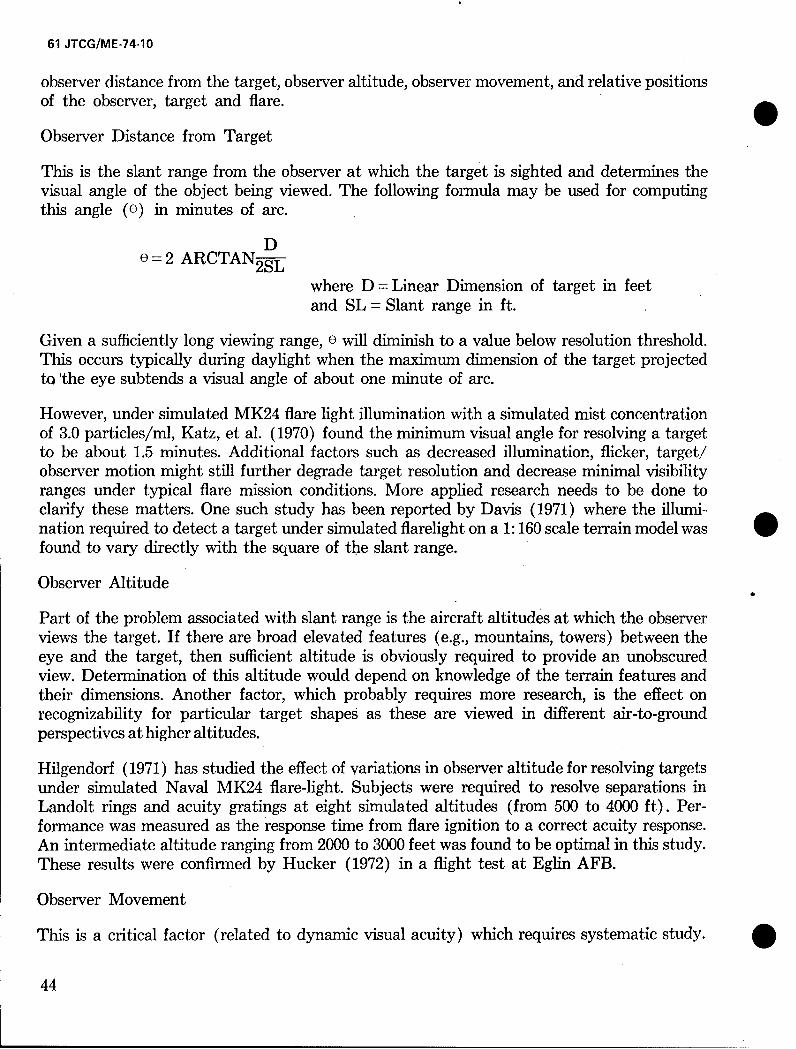
61 JTCG/ME-74-10
observer distance from the target, observer altitude, observer movement, and relative positionsof the observer, target and flare.
Observer Distance from Target
This is the slant range from the observer at which the target is sighted and determines thevisual angle of the object being viewed. The following formula may be used for computingthis angle (0) in minutes of arc.
D0 - 2 ARCTAN 2sL
where D = Linear Dimension of target in feetand SL = Slant range in ft.
Given a sufficiently long viewing range, 0 will diminish to a value below resolution threshold.This occurs typically during daylight when the maximum dimension of the target projectedto 'the eye subtends a visual angle of about one minute of arc.
However, under simulated MK24 flare light illumination with a simulated mist concentrationof 3.0 particles/ml, Katz, et al. (1970) found the minimum visual angle for resolving a targetto be about 1.5 minutes. Additional factors such as decreased illumination, flicker, target/observer motion might still further degrade target resolution and decrease minimal visibilityranges under typical flare mission conditions. More applied research needs to be done toclarify these matters. One such study has been reported by Davis (1971) where the illumi-nation required to detect a target under simulated flarelight on a 1:160 scale terrain model wasfound to vary directly with the square of the slant range.Observer Altitude
Part of the problem associated with slant range is the aircraft altitudes at which the observerviews the target. If there are broad elevated features (e.g., mountains, towers) between theeye and the target, then sufficient altitude is obviously required to provide an unobscuredview. Determination of this altitude would depend on knowledge of the terrain features andtheir dimensions. Another factor, which probably requires more research, is the effect onrecognizability for particular target shapes as these are viewed in different air-to-groundperspectives at higher altitudes.
Hilgendorf (1971) has studied the effect of variations in observer altitude for resolving targetsunder simulated Naval MK24 flare-light. Subjects were required to resolve separations inLandolt rings and acuity gratings at eight simulated altitudes (from 500 to 4000 ft). Per-formance was measured as the response time from flare ignition to a correct acuity response.An intermediate altitude ranging from 2000 to 3000 feet was found to be optimal in this study.These results were confirmed by Hucker (1972) in a flight test at Eglin AFB.
Observer Movement
This is a critical factor (related to dynamic visual acuity) which requires systematic study.
44
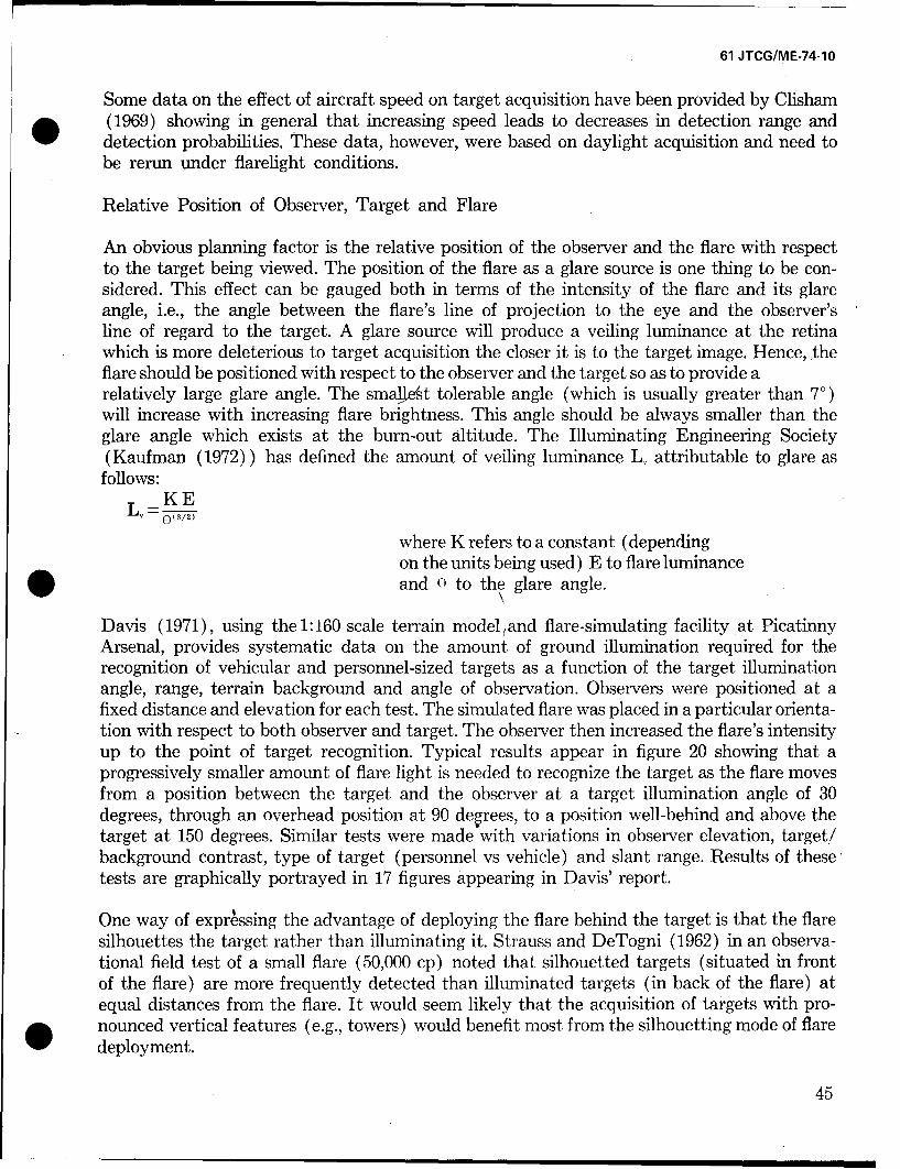
61 JTCG/ME-74-10
Some data on the effect of aircraft speed on target acquisition have been provided by Clisham* (1969) showing in general that increasing speed leads to decreases in detection range and
detection probabilities. These data, however, were based on daylight acquisition and need tobe rerun under flarelight conditions.
Relative Position of Observer, Target and Flare
An obvious planning factor is the relative position of the observer and the flare with respectto the target being viewed. The position of the flare as a glare source is one thing to be con-sidered. This effect can be gauged both in terms of the intensity of the flare and its glareangle, i.e., the angle between the flare's line of projection to the eye and the observer'sline of regard to the target. A glare source will produce a veiling luminance at the retinawhich is more deleterious to target acquisition the closer it is to the target image. Hence,theflare should be positioned with respect to the observer and the target so as to provide arelatively large glare angle. The smallest tolerable angle (which is usually greater than 70)will increase with increasing flare brightness. This angle should be always smaller than theglare angle which exists at the burn-out altitude. The Illuminating Engineering Society(Kaufman (1972)) has defined the amount of veiling luminance L, attributable to glare as
follows:SKE
L, -03/2)
where K refers to a constant (dependingon the units being used) E to flare luminanceand 0 to the glare angle.
Davis (1971), using the 1:160 scale terrain model and flare-simulating facility at PicatinnyArsenal, provides systematic data on the amount of ground illumination required for therecognition of vehicular and personnel-sized targets as a function of the target illuminationangle, range, terrain background and angle of observation. Observers were positioned at afixed distance and elevation for each test. The simulated flare was placed in a particular orienta-tion with respect to both observer and target. The observer then increased the flare's intensityup to the point of target recognition. Typical results appear in figure 20 showing that aprogressively smaller amount of flare light is needed to recognize the target as the flare movesfrom a position between the target and the observer at a target illumination angle of 30degrees, through an overhead position at 90 deIrees, to a position well-behind and above thetarget at 150 degrees. Similar tests were made with variations in observer elevation, target/background contrast, type of target (personnel vs vehicle) and slant range. Results of these*tests are graphically portrayed in 17 figures appearing in Davis' report.
One way of expressing the advantage of deploying the flare behind the target is that the flaresilhouettes the target rather than illuminating it. Strauss and DeTogni (1962) in an observa-tional field test of a small flare (50,000 cp) noted that silhouetted targets (situated in frontof the flare) are more frequently detected than illuminated targets (in back of the flare) atequal distances from the flare. It would seem likely that the acquisition of targets with pro-nounced vertical features (e.g., towers) would benefit most from the silhouetting mode of flaredeployment.
45
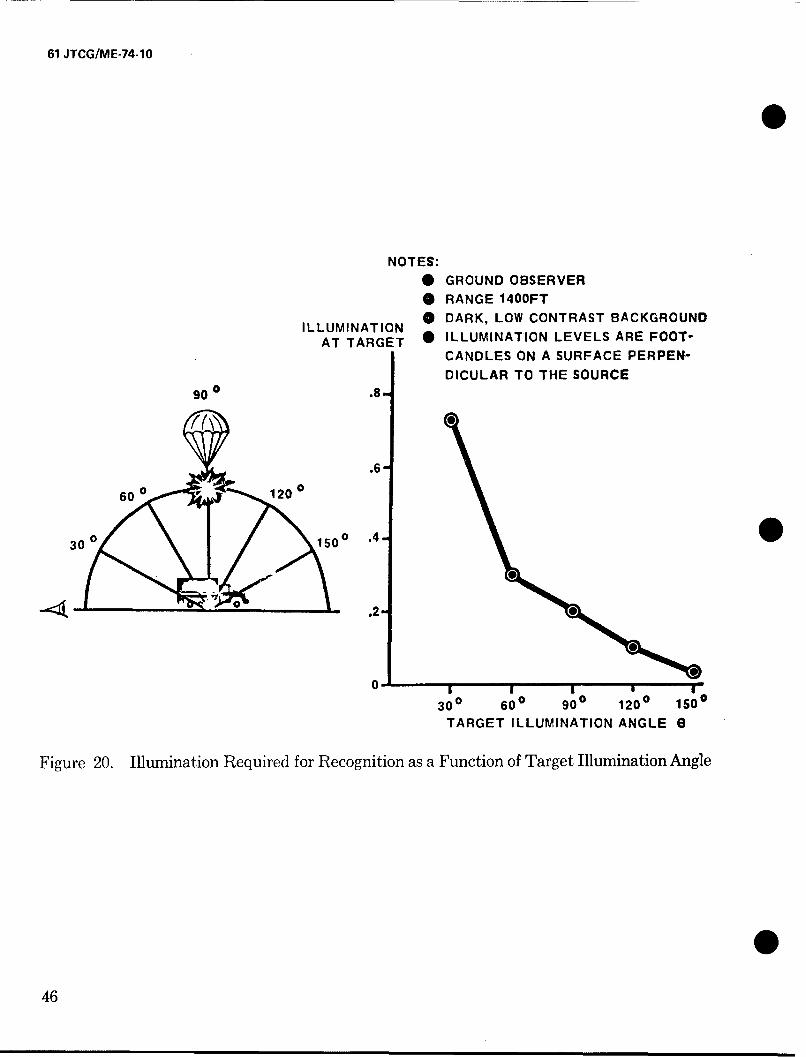
61 JTCG/ME-74-10
NOTES:
0 GROUND OBSERVER
* RANGE 1400FT
ILLUMINATION 0 DARK, LOW CONTRAST BACKGROUND
AT TARGET * ILLUMINATION LEVELS ARE FOOT-
CANDLES ON A SURFACE PERPEN-DICULAR TO THE SOURCE
900 .8
.6
60 0 v120 0
30 0 1500 .4
00
0-I I I l
300 600 900 1200 1500
TARGET ILLUMINATION ANGLE G
Figure 20. Illumination Required for Recognition as a Function of Target Illumination Angle
046
61 JTCG/ME-74-10
SECTION IV
0 CONCLUSIONS
In this paper an attempt has been made to extract,. integrate and evaluate data from currentresearch which pertains to the more effective design and utilization of illuminating flares. Theprincipal criterion of effectiveness is the improved capability for air-to-ground visual acquisitionof targets. Various research techniques for gathering data on flare effectiveness have been con-sidered and relevant factors'have been reviewed under the major headings of candle composi-tion, deployment, wind drift, atmosphere, target and observer.
The information contained in this report is addressed to those Armed Forces personnel whostudy, design and use systems involving illuminating flares for target acquisition. In additionto providing them guidance on flare effectiveness, an effort has been made to review currentresearch programs and to suggest areas requiring further investigation.
A disportionate amount of pyrotechnic research apparently has been expended in areas relatedto composition development and parachute deployment with too little concern for the amountor type of illumination actually needed to acquire a target. On the other hand, relatively littleeffort has been expended, within the context of mission requirements, which relates flare effec-tiveness factors to the responses of human observers. Without knowledge of such relationships,one cannot confidently evaluate the relative merits of alternative flare systems or of proposedinnovations.
0
047
61 JTCG/ME-74-10
REFERENCES
Army, Hq., Field Manual-Battlefield, Illumination, FM 20-60, Hq, Dept of the Army, Jan1970.
Army Materiel Command. Engineering Design Handbook, Military Pyrotechnics Series,Part One, Theory and Application, AMC Pamphlet No. 706-185, Army Materiel Command,Washington, D.C., April 1967.
Blunt, R. M., & Schmeling. Study of Psychophysical Factors of Vision and Pyrotechnic LightSources. Technical Report AFATL-TR-68-17, Air Force Armament Laboratory, Eglin AFB,FL., Feb 1968.
Blunt, R. M. Spectral Distribution of Different Regions of Illuminating Flare Flames. RDTR
No. 220, Naval Ammo Depot, Crane, Ind., Dec 1972.
Bradley, G. Visibility Model. RDTR No. 151, Naval Ammo Depot, Crane, Ind., Nov 1969.
Bradley, G. S., & Lohkamp, C. E. An Analysis to Determine the Effect of the Atmosphere onthe Contrast Pioduced by Flare Illumination. RDTN No. 229, Naval Ammo Depot, Crane,Ind., Jan 1973.
Brooks, W. Methodology Study of Illuminating Pyrotechnic Test and Evaluation. First PartialReport. Y.P.G. Project No. 6002, Yuma Proving Ground, Yuma, Ariz., Jan 1970. 0Brooks, W. Methodology Stu.ý, of Illuminating Pyrotechnic Test and Evaluation. Second andFinal Partial Report. Y.P.G. Report 0052, Yuma Proving Ground, Yuma, Ariz. Oct 1970.
Carlson, B. & Jewsbury, W. Advanced Development of the Packaging and Deployment of aShielded Flare. Technical Report AFATL-TR-69-124, Air Force Armament Laboratory,Eglin AFB, FL., Sept 1969.
Carlson, B. & Jewsbury, W. Flight Feasibility Testing of an Improved Target IlluminatingFlare. Technical Report AFATL-TR-68-118, Air Force Armament Laboratory, Eglin AFB,FL., Oct 1968.
Clisham, W. F. Jr. Advanced Concept Studies of Aircraft Flares and Dispensing Systems-PartII: Operational Analysis and Human Factors Affecting Second Generation Flare IlluminationStudies. Report R-1935, Frankford Arsenal, Philadelphia, PA, Oct 1969.
Cohen, H. N. & Kottler, G. F. The Optimum Height of a Burning Flare. Tech Report 2091,Picatinny Arsenal, Dover, N.J., Oct 1954.
Craven, T. D. Operational Test and Evaluation of the LUU-2/B Airborne Flare. TAC TR69-55A, USAF Special Operations Force, TAC, USAF, Eglin AFB, FL., July 1970.
48

61 JTCG/ME-74-10
Davidson, C. I. The Effects of Flare Tunnel Geometry and Reflectivity on Light Measure-ments. Pyrotechnics Laboratory Information Report, Picatinny Arsenal, April 1970.
Davis, R. B. Results of Air Illumination Requirement Study using a Pyrotechnic TerrainModel. Technical Report 4184, Picatinny Arsenal, Dover, N.J., Nov 1971.
Davis, S. G. Illumination Meter for Low Level Light Measurements. Pyrotechnics LaboratoryI-formation Report, Picatinny Arsenal, Dover, N.J. April 1970.
Davis, R. B. and Tyroler, J. F. An Investigation of the Effect of Change in Flare Intensity onthe Recognition of Vehicular Size Targets, Pyrotechnic Division Information Report IR 5-72,Picatinny Arsenal, Dover, N.J., Dec 1972.
Douda, B. E. Relationships Observed in Colored Flames. RDTR No. 45, Naval Ammo Depot,Crane, Ind., 1964.
Douda, B. E. Emission Studies of Selected Pyrotechnic Flames. Journal of Optical Society ofAmerica, 55(7), 1965.
Douda, B. E. Twenty Five Million Candle Cast Flares, Diameter and Binder Study. RDTRNo. 105, Naval Ammo Depot, Crane, Ind., Jan 1968.
Douda, B. E. Determination of the Amount of Energy Radiated in the Visible by an Illumi-nating Flare Flame. RDTN No. 135, Naval Ammo Depot, Crane, Ind., July 1968.
Douda, B. E. Pyrotechnic Flare Spectroscopy. RDTR No. 206, Naval Ammo Depot, Crane,Ind., June 1972.
Douda, B. E. Atlas of Radiant Power Spectra of Four Flare Formulas at Eight Levels of Am-bient Pressure. RDTR No. 205, Naval Ammo Depot, Crane, Ind., June 1972.
Douda, B. E. and Bair E. Visible Radiation from Illuminating-Flare Flames: Strong EmissionFeatures. Journal of Optical Society of America, 55 (7), 1965.
Ellern, H. Military and Civilian Pyrtechnics. Chemical Publishing Company, New York, 1968.
Ernst, B. G. Functional and Effectiveness Test of the Improved Target Illumination Flare(Shielded Flare). Technical Report ADTC-TR-72-130, Armament Development and TestCenter, Eglin AFB, FL., Dec 1972.
Feagans, J. W. An Evaluation of Flame Intensity by Comparison of Flares. RDTR No. 98-23.
Naval Ammo Depot, Crane, Ind., May 1967.
Graham, C. H. et al. Vision and Visual Perception. John Wiley and Sons, New York 1965.
Hamrick, J. T. Proceedings of First Pyrotechnic Seminar. Areas for further Exploratory De-0 velopment. RDTR No. 131, Denver Research Inst., Denver, Col., Oct 1968
49
61 JTCG/ME-74-10
Hamrick, J. T., Blackshear, P. L. Jr., and Stanitz, J. D. Exploratory Development of Illumina-tion Flares. Aerospace Research Corp., Roanoke, VA., Aug 1968.
Hart, D. Research and Development Progress in Military Pyrotechnics. R&D Lect. #24,Picatinny Arsenal, Dover, N.J., Feb 1955.
Hilgendorf, R. L. Visual Search and Detection under Simulated Flarelight. AMRL-TR--68-112(11). Aerospace Medical Research Laboratory, W-PAFB, OH., Jan 1969.
1
Hilgendorf, R. L. Visual Performance with Simulated Flarelight: Effects of Flare-IgnitionAltitude. Human Factors, Aug 1971, 13(4).
Hilgendorf, R. L. "Visual Acuity" under Simulated Flarelight: Effects of Observer Altitude.Aerospace Medical Association, 1971 Annual Scientific Meeting.
Hilgendorf, R. L. Current Research in Simulated Battlefield Illumination: Effects of FlareShielding, Proceedings, Psychology in the Air Force, 2nd Annual Symposium, USAF Academy,April 1971.
Hilgendorf, R. L. Air-To-Ground Target Acquisition with Flare Illumination. Agard Confer-ence Preprint No. 100. On Air-to-Ground Target Acquisition, NATO Advisory Group for Aero-space Research and Development, June 1972. SHucker, J. A. Testing for Flare Simulation Study Validation. ADTC-TR-72-3, ArmamentDevelopment and Test Center, Eglin AFB, FL., Jan 1972.
Jewsbury, W. Study, Analysis and Experimentation of an Improved Target IlluminatingFlare. Technical Report AFATL-TR-68-2, Air Force Armament Laboratory, Eglin AFB, FL,Jan 1968.
Johnson, D. M. Proposed Kinetics and Mechanics of Illuminant Flares: Maximizing Efficiency,RDTR No. 32, Naval Ammo Depot, Crane, Ind., Jan 13, 1966.
JTCG/ALNNO. Results of YPG PER Site Test on Six Aircraft Flares. Working Party for.Pyrotechnics, Joint Technical Coordinating Group for Air Launched Non-Nuclear Ordinance.Sept 1971.
Katz, S., Ase, P. K., Raisen E., and Hilgendorf, R. L. Visual Performance with SimulatedFlarelight in Artificial Clouds. AMRL-TR-69-121, Aerospace Medical Research Laboratory,W-PAFB, OH., Jan 1970.
Kaufman, J. E. Illuminating Engineering Society Lighting Handbook. Fifth Ed., Published byIllum Eng Soc, 1972.
50
61 JTCG/ME-74-10
Kemp, J. L. Proceedings of First Pyrotechnic Seminar. Math Simulation Models. RDTR No.* 131. Denver Research Inst., Denver, Col., Oct 1968.
Laswell, J. E. Study of the Optimum Suspension of a High Intensity Parachute Flare. RDTNNo. 30, Naval Ammo Depot, Crane, Ind., May 1963.
Laswell, J. E. An Investigation to Optimize Illumination Characteristics of a Parachute Flare(MK 45 Type). RDTN No. 202. Naval Ammo Depot, Crane, Ind., Nov 1971.
Laswell, J. E. A Method to Simulate the Dynamical Evaluation of Aircraft Parachute Flares.RDTN No. 206, Naval Ammo Depot, Crane, Ind., Feb 1972.
Laswell, J. E. A Mathematical Model which Simulates Non-Isotropic Light Emission atYuma Grounds PER Site. RDTN No. 210, Naval Ammo Depot, Crane, Ind., July 20, 1972.
Lazarus, M. Measurements at an Outdoor Flare Test Facility and a Relation To Ground Illu-mination. Pyrotechnics Laboratory Information Report. Picatinny Arsenal, Dover, N.J., May1969.
Lazarus, M. Picatinny Flare Tower Objective and Comparison to a Flare Tunnel. PyrotechnicsLaboratory Information Report. Picatinny Arsenal, Dover, N.J., 1971.
* Lohkamp, C. W. Visibility under Pyrotechnic Flare Illumination and of Pyrotechnic Signals.Naval Ammo Depot, Crane, Ind., 1970.
Lohkamp, C. W. Fleet Use of 5"/54 Illuminating Projectile. RDTN No. 228. Naval AmmoDepot, Crane, Ind., Dec 1972.
Lohkamp, C. W. Validation Flight Test. RDTN No. 231. Naval Ammo Depot, Crane, Ind.,Jan 1973.
Middlebrooks, D. E. & Kaye, S. M. The Effects of Processing on Pyrotechnic Compositions.Part II: Statistical Analysis of Effects of Particle Size on Burning Rate and Illuminance forConsolidated Pyrotechnic Items. Technical Report No. 3253, Picatinny Arsenal, Dover, N.J.,Jan 1966.
Naval Ammo Depot, Crane, Ind. Predictions of Shielded Flares Capability. Letter to Naval AirSystems Command, Naval Ammo Depot, Crane, Ind., Nov 1970.
Smith, C., Lazarus, M., and Davidson, C. True Effects of Air Drop Velocity on Flare Output.Pyrotechnic Laboratory Information Report. Picatinny Arsenal, Dover, N.J., Nov 1972.
Starrett, C, M. A Computer Program for the Analysis of Illumination Patterns Resulting fromN Separated Flares, Tech Memo 1458, Picatinny Arsenal, Dover, N.J., Dec 1964.
51
61 JTCG/ME-74-10
Starrett, C. M. A Collection of the Illuminating Patterns Resulting from N Separated Flares.Tech Memo 1620, Picatinny Arsenal, Dover, N.J., June 1965.
Stoval, R. J. General Description of MAPI Data Acquisition Systems. RDTR No. 38. NavalAmmo Depot, Crane, Ind., 1966.
Strauss, P. S. & DeTogni, G. R. Personnel Target Acquisition under Flare Illumination. Tech-nical Report 3012, Picatinny Arsenal, Dover, N.J., July 1962.
Tanner, J. Effect of Binder Oxygen Content on Adiabatic Flame Temperature of PyrotechnicFlares. RDTR No. 181, Naval Ammo Depot, Crane, Ind., August 1972.
Tyroler, J. F. Illuminating Flare Performance and Illuminating Requirements. UnpublishedReport, Picatinny Arsenal, Dover, N.J., 1971.
Tyroler, J. F. The Pyrotechnic Terrain Model, A New Dimension in Pyrotechnic Design De-scription and Initial Results. Tech Report 4075. Picatinny Arsenal, Dover, N.J., 1971.
Weasner, M. H. Detection of Ground Targets under Flare Illumination. Tech Report 3266,Picatinny Arsenal, Dover, N.J., 1965.
Wildridge, J. E.Design and Tests of Experimental High Intensity Flare Systems. RDTR No.75, Naval Ammo Depot, Crane, Ind., Aug 1966.
52
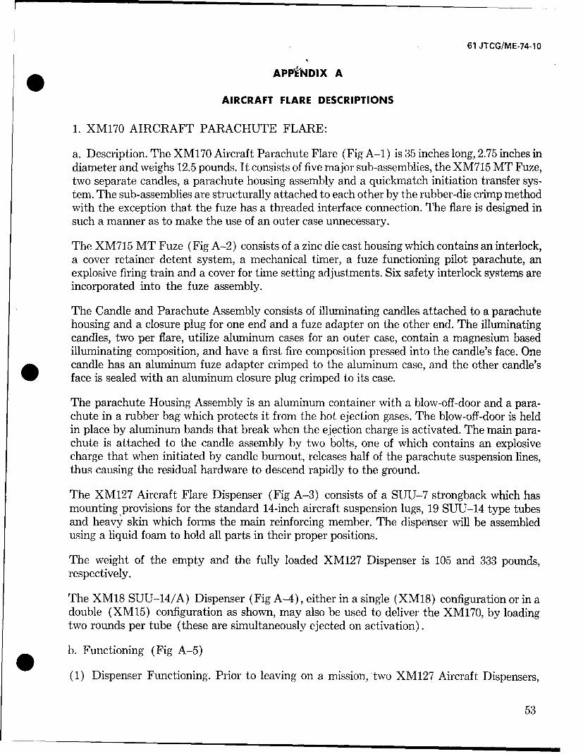
61 JTCG/ME-74-10
APP"NDIX A
AIRCRAFT FLARE DESCRIPTIONS
1. XM170 AIRCRAFT PARACHUTE FLARE:
a. Description. The XM170 Aircraft Parachute Flare (Fig A-i) is 35 inches long, 2.75 inches indiameter and weighs 12.5 pounds. It consists of five major sub-assemblies, the XM715 MT Fuze,two separate candles, a parachute housing assembly and a quickmatch initiation transfer sys-tem. The sub-assemblies are structurally attached to each other by the rubber-die crimp methodwith the exception that the fuze has a threaded interface connection. The flare is designed insuch a manner as to make the use of an outer case unnecessary.
The XM715 MT Fuze (Fig A-2) consists of a zinc die cast housing which contains an interlock,a cover retainer detent system, a mechanical timer, a fuze functioning pilot parachute, anexplosive firing train and a cover for time setting adjustments. Six safety interlock systems areincorporated into the fuze assembly.
The Candle and Parachute Assembly consists of illuminating candles attached to a parachutehousing and a closure plug for one end and a fuze adapter on the other end. The illuminatingcandles, two per flare, utilize aluminum cases for an outer case, contain a magnesium basedilluminating composition, and have a first fire composition pressed into the candle's face. One
* candle has an aluminum fuze adapter crimped to the aluminum case, and the other candle'sface is sealed with an aluminum closure plug crimped to its case.
The parachute Housing Assembly is an aluminum container with a blow-off-door and a para-chute in a rubber bag which protects it from the hot ejection gases. The blow-off-door is heldin place by aluminum bands that break when the ejection charge is activated. The main para-chute is attached to the candle assembly by two bolts, one of which contains an explosivecharge that when initiated by candle burnout, releases half of the parachute suspension lines,thus causing the residual hardware to descend rapidly to the ground.
The XM127 Aircraft Flare Dispenser (Fig A-3) consists of a SUU-7 strongback which hasmounting provisions for the standard 14-inch aircraft suspension lugs, 19 SUTJ-14 type tubesand heavy skin which forms the main reinforcing member. The dispenser will be assembledusing a liquid foam to hold all parts in their proper positions.
The weight of the empty and the fully loaded XM127 Dispenser is 105 and 333 pounds,respectively.
The XM18 SUU-14/A) Dispenser (Fig A-4), either in a single (XM18) configuration or in adouble (XM15) configuration as shown, may also be used to deliver the XM170, by loadingtwo rounds per tube (these are simultaneously ejected on activation).
b. Functioning (Fig A-5)
(1) Dispenser Functioning. Prior to leaving on a mission, two XM127 Aircraft Dispensers,
53
61 JTCG/ME-74-10
IGNITER CORD ALUMINUN PARACHUTE HOUSING DOOR
ALUMINUN CANDLE CASE ALUMINUM BAND
CANDLE COMPOSITION 36O0 CRIMP
ENDFUJZE EXPLOSIVE BOLT PLAIN BOLT CLOSURE
FILLER PLUG
TYGON PARACHUTE PACK FIRST FIRETUBING ASSEMBLY
SAFETY ALUMINUN PARACHUTE EJECTION CHARGESPRING HOUSING
XM170 AIRCRAFT PARACHUTE FLARE
FIG A-1
054
61 JTCG/ME-74-10
PRONG ASSEMBLY
IGNITER COMPOSITION PRIMER SLIDER SHEAR PINS TIMER RELEASE PIN CR COVER BOSS
COVER LOCK PIN
FUZE PARACHUTERISER GUIDE
'd RING h i-PARACHUTE
ONE PIECE - "FUZE SETTING
PRIMER : SEAR ASSEMBLY WINDOW
ONE PIECEFIRING PIN - "-COVER
ONE PIECESEAR ASSEMBLY
COICAL SPRIGTIMER
SS-COVER LOCK PIN
PARACHUTEEXTRACTOR LINE
-TIMER SHAFT
o RING
FUZE PARACHUTE
PARACHUTEEXTRACTOR LINE
ONE PIECE
SEAR ASSEMBLY - ,PARACHUTE.'01 RING
FUZE PARACHUTE X -OSN
FIRING PIN- /
XM-715 MECHANICAL TIME FUZE
FIG A-2
55
61 JTCG/ME-74-1O
56
61 JTCG/ME-74.1O
14"SUSPENSION LUG
XM-18 AIRCRAFT DISPENSER
BREECH AND EJECTION CARTRIDGE ASSEMBLYELICTRICAL JUMPER PLUG
XM-15 AIRCORAFT DISPENSER AND FAE
FIG A-4
57
61 JTCG/ME-74. 11
0
0
-I= L
U-
UU
I I-
4X
00
0 -K- a - wua.
IA
xxIa 1A U m
uIn
'ow
58
61 JTCG/ME-74-10
fully loaded with XM170 Aircraft Parachute Flares, are mounted on the Aircraft's externalsuspension system and connected electrically to the appropriate fire control circuit. The air-craft's fire control circuit has two switches, exclusive of the firing button, an arming switch,which shorts out the firing circuit until placed in the armed position, and a selector switch whichallows the choice of a single flare from either left, right or both dispensers. These switches canbe set, reset or changed anytime during the mission.
In operation, the pilot triggers his firing button on the control panel which closes a circuit froma power supply to the externally mounted dispensers. The firing command pulse passesthrough a RADHAZ filter and the arming switch (in the armed position) to the selector switchwhich is always set for single tube fire of either the left, right or both dispensers. The firingpulse then goes through the rotary selector switch and activates one of the ejection cartridges.The ejection cartridge builds up a high pressure behind the obturation piston and spring assem-bly and after providing enough force to shear the end plug rivets, ejects in order, the end plug,one XM170 Aircraft Parachute Flare and the piston and spring assembly.
(2) Fuze Functioning. When the dispenser tube is activated, the ejection charge gas pressureagainst the fuze cover is sufficient to completely compress the conical spring by moving thefuze cover forward; this will move the interlock assembly to the released position, releasing apin in the timer's gear train and thus allowing the timer to function. The conical spring at thispoint has moved the fuze cover forward against the two cover retaining pins. When the pre-viously set time is reached by the mechanical timer, a cam within the timer releases the twocover retaining pins. These pins are spring-loaded and move radially inward when released bythe cam, freeing the fuze cover. As the cover is pushed off by the conical spring, two separateparallel actions transpire, the out-of-line primer moves into alignment with the firing pin, anda parachute extractor attached to the fuze cover pulls the fuze parachute out of its cavity andaids in its opening. The resultant opening shock force of parachute deployment, shears a pinand rotates a sear mechanism away from the spring-loaded firing pin. The firing pin, thusreleased, impinges upon the now aligned percussion primer, which propagates to a two seconddelay (allowing the fuze parachute to stabilize and retard the round). The delay transfers toan ignition composition containing granules of boron-potassium nitrate. The resulting totaloutput of the propagating ignition composition is directed toward the aft end of the fuzehousing.
(3) Flare Functioning. When the fuze functions, the output of particles and gases simulta-neously ignites both the first fire of the nearest candle (which blows off the fuze !adapter)and the quickmatch transfer line. The transfer line instantly ignites both the black powderparachute ejection charge and the second candle's first fire (which blows off the end closure).As the ejection charge burns, it forces the parachute against the blow-off-door, finally shearingthe aluminum bands. As the door is ejected, it pulls out the parachute and aids in its deploy-ment through the use of a deployment ribbon attached to the door and folded into the para-chute assembly. The parachute now suspends the flare system in a horizontal mode leavingthe candles to provide useful illumination. As the candles burnout, one candle ignites anexplosive element in one of the parachute attachment bolts, freeing half the parachute shroudlines. Freeing half of the parachute shroud lines allows the parachute to spill its air, collapse andutilize the weight of the aluminum center section to aid in its descent to the ground, thus remov-ing the hazard that expanded parachute flares normally present to operational aircraft.
59
61 JTCG/ME-74-10
2. M8A1 AIRCRAFT PARACHUTE FLARE
a. Description. The M8A1 Aircraft Parachute Flare (Fig A-6) is 25.42 inches long by 4.25inches in diameter and weighs 17.6 pounds. The flare consists of a candle, parachute assemblyand two friction igniters. This item does not contain a delay type time fuze.
The illuminant charge weighs 10 pounds and is contained in a paper tube encased in a zincsheathing. The illuminant composition consists of barium nitrate, magnesium, aluminum,sodium oxalate, and small percentages of linseed and castor oils. A quickmatch passes throughthe length of the center tube of the illuminant assembly and provides the means of relayingthe flame from the igniters to the priming composition and thence, in turn, to the first-firecomposition and illuminant charge. A top seal of fire clay separates the igniters from the illu-minant charge.
The aluminum base block fits immediately over the top seal. This base block holds screws whichfasten the parachute case to the illuminant case. The base block also is an anchorage for thesuspension cable and contains the two friction igniters which consist of a friction compositionand a friction wire coated with red phosphorus. One end of the friction wire is attached to thesuspension cable above the shock absorber. So that an appreciable pull will be required to oper-ate the igniters, the friction wires are secured against the base block by an aluminum safetystrip secured, in turn, by a brass retainer. The shock absorber consists of the flexible steel sus-pension cable encased in a hand-drawn copper tube, the whole formed into a closely woundhelix. A paper safety disk closes the cup housing the shock absorber assembly. The disk must beremoved by a jerk on the suspension cable before the friction igniters will fire.
The parachute is made of sill -, synthetic fabric and is 15 feet in diameter. The shroud linesare braided cotton cord. havinýg a 100-pound breaking strength. The shroud lines are 14 feet inlength and are attached to the suspension cable by means of the suspension cable spool. Twopilot disks, through which the parachute pullout cord passes, are assembled underneath thehangwire cover.
The parachute case is closed by the hangwire cover which is in the position of a cup openingoutward. The hangwire with swivel loop is not permanently attached to the cover, but is as-sembled to the hangwire plug passing through a central hole in the cover and held by a releasespring on the underside of the cover. One end of the release spring is held in a clip soldered orwelded to the underside of the hangwire container. The other end passes through the centralhole in the release plug. The release spring is held in this position by the parachute case. Assoon as the hangwire cover is free of the case, the spring releases the hangwire plug, then thehangwire and its plug separate from the cover.
A shipping cover, held by a tear strip, protects the parachute case end of the flare. A closingcover is press fitted over the open end of the illuminant portion of the flare and is loose enoughto be blown off when the composition begins to burn.
b. Functioning (Fig A-7)
When the flare is released from the aircraft, the hangwire cover is removed by the resulting
60
61 JTCG/ME-74-10
"BASE BLOCK (ILLUMINANT RETAINER)
RELrEASE SPRING IGNITERS CENTER TURF
TEAR STRIP LOOP PILOT DISC SHOCK ABSORBER FRICTION WIRE
OUICKNIAICH PRI <-'ý'COMPOSITION
"HANGWI RE r ' :=
PLUG (HANGWIRE) C Ifi C CO!
' SHIPPING COVER R LINE
PARACHUTE RISER LINE TOP SEALTEAR STRIP I ''I-I COMrO;ITON
PARACHUTE PULLOU CORD SUPENSION LINES LLUMIE'N1 CHARGE
M8A1 AIRCRAF : 1'T A ,K {•
FIG A-6
O
61 JTcG/rQ�E-7&1o
C1� j
i�r7
(2
0
A0
62.
61 JTCG/ME-74-10
jerk of the lanyard on the hangwire. The flare is now free of the aircraft. The pilots disks andparachute pull-out cord withdraw the parachute from its case and the parachute deploys. Assoon as the hangwire cover leaves the case, the release spring pulls away from the hangwire plugand the cover is free to fall away from the hangwire.
The sudden pull of the deployed parachute causes the suspension cable, shock absorber assem-bly and safety disk to pull out of the case, and simultaneously cause the friction wire to pullthrough the friction composition.
The resultant flame is transmitted by the quickmatch to the priming composition and, in turn,to the first-fire composition and the illuminant charge. The pressure produced by the burningcomposition blows off the closing cover on the illuminant end of the flare, resulting in propercandle operation.
3. LUU-2/B AIRCRAFT PARACHUTE FLARE
a. Description. The LUU-2/B Aircraft Parachute Flare (Fig A-8) is 36 inches long, 4.87inches in diameter and weighs approximately 291/2 pounds. The flare consists of four major sub-assemblies, the timer-end cap assembly, the parachute suspension system, the ignition systemand the case assembly with the tamped candle. The flare is designed so that the outer aluminumcase is partially consumed during candle burning.
The timer-end cap assembly consists of a timer and related hardware enclosed in a lexanplastic housing. The setting dial knob and calibrated markings (from 500 to 10,500 feet of fall)are coated with a luminous paint which has an after glow from 8 to 10 hours after being exposedto light. The timer consists of a simple clock mechanism in which the main spring is woundtighter, if more than a 500 foot free fall is desired, as the timer dial knob is set to the desireddrop distance. The timer is kept at a 500 foot setting during storage. A small drogue bag ispacked in a compartment located in the timer cover. The plastic cover over the drogue bag com-partment is removed when the timer dial knob is pulled. The purpose of the drogue bag is toprevent the flare from developing an excessively high rate of tumbling; thus, should tumblingreach 100 to 200 revolutions per minute, the drogue bag is deployed.
The parachute suspension system utilizes an 18 foot diameter cruciform shaped canopy, forgood stability. Two riser cables connect the parachute to a bulkhead separating the parachutecompartment from the remainder of the flare assembly. One cable is attached to an explosivebolt for parachute dump at candle burn out.
The ignition system utilizes a lanyard, which is attached to one of the parachute riser cables.This lanyard is led through the bulkhead and past the candle in an internal raceway along theside of the aluminum case leading to the ignition assembly in the ignitor housing near thecandle's face. The lanyard is attached to a triggering mechanism consisting of a bell crank,firing pin housing, firing pin spring, shear pin, pivot pin and primer. The firing train sequenceof propagation is primer-ignition pellets-ignition wafer-candle composition.
The illumination candle is a tamp cast sodium nitrate-magnesium pyrotechnic composition
63
2SA
-- I
#L'i M
loAs

61 JTCG/ME-74-10
which is loaded directly into the flare's lined out aluminum container. The candle grain is* approximately 22 inches long.
b. Functioning (Fig A-9). During dispenser up-loading, a lanyard is attached to the dial knobon the flare timer. At launch; the timer dial knob is pulled out of the timer (approximately 35pounds force), starting the clock mechanism. After the preset time (drop distance) has elapsed,the three locking pawls in the timer assembly, which are maintained in place by a rotary cam,are released.
The three pawls retract releasing the timer-end cap assembly. The spring, located between thetimer assembly and packed parachute, expels the timer assembly which is attached to the topof the parachute by a cord having sufficient strength to initiate removal of the parachute fromthe flare case and subsequently breaking to separate the timer assembly from the parachute.
As the parachute system deploys and its main cables are pulled taut, the ignition lanyard,having insufficient slack to accommodate the cable movement, is pulled to activate the ignitionsystem. The ignition lanyard must exert a force of 50 pounds to break the shear pin. Then, theignition lanyard rotates a bell crank which cocks and releases the firing pin against the primer.The primer ignites a small charge of pelletized boron-potassium nitrate, which in turn ignitesa propellant wafer, which produces sufficient heat for candle ignition.
Pressure build-up during candle ignition blows out two pressure relief plugs in the ignitor hous-ing. Most of the' ignitor housing is consumed by the burning flare; however, the last small piecesof the aluminum ignitor housing fall free. Just before candle burn out, the explosive boltfunctions to release one of the suspension cables causing the parachute to dump.
4. MK45 AIRCRAFT PARACHUTE FLARE
a. Description. The MK45 Aircraft Parachute Flare (Fig A-10) is 36 inches long, 4.87 inchesin diameter and weighs 28 pounds. The flare consists of a fuze assembly, an outer container, thecandle assembly, a suspension ignition assembly and a parachute assembly.
The fuze assembly is used to control the ejection altitude in relation to the launch altitude.it does not directly control candle ignition. The fuze consists of an internal disconnect, astriker and plunger assembly, a 1.5 second minimum fixed delay element, a time delay fuzecord and an expelling charge. Fuze setting is accomplished with a single yellow dial indicatorwhich can be set at 15 different positions (500 to 14,000 feet of fall). Raised projections atSAFE and at each setting point facilitate setting the fuze in total darkness. A spring loadeddetent holds the dial indicator at the selected setting.
The outer container is an aluminum tube sealed at one end by an O-ring and the fuze assembly,and at the other end by another 0-ring and an aluminum cap.
The candle assembly, consisting of the illuminating composition, candle case and explosivebolt assembly, is located directly behind the fuze assembly in the forward half of the outercontainer. The candle's ignition surface is faced away from the fuze end of the outer container
65
61 JTCG/ME-74-1O
cof
C-CM
LiiC
Lii
00
Liij
-LJ
C'.j
-J J-00I
owEz
CL u<
LLJ-D-
0 LLI L066)
61 JTCG/ME-74-1O
END VIEW OF FUZE~WITH END CAP REMOVED) ~ ~ AU' A
EJECTION SETTINGS M R-- IRC AFEJCINDIAL INDICATOR PARo OO~ACHUTE FLARE
STRIKER 0 10. 06....INSTRUCTION TAG
cPOSITIVE DELAY 00 %(2 SECi ~SAFETY CLIP
-BLACK POWDER PELLET F ILLUM INATIONPACHT P-F EPELANTCOMOSIION CONTAINER DROGUE CHUTE
CANDLE TUBE 1
FGAS CHECK -PRIMER OUTER CONTAINER
p~CABLE ,-DETONATOR 1<V /0 `7
EJECTION TIME DELAY FUSE EXPLOSIVE BOLT DEEA EPLOMETNA
"-INTERNAL DISCONNECT FUZE fRN IADAPTOR IRN I
DETACHABLE FUZE ASSEMBLY PARACHUTE ASSEMBLY,
ATTACHMENT LOOP IGNITER ASSEMBLY
FIG A-10
67
61 JTCG/ME-74-10
and a gas check is used to insure that ejection. charge gases do not prematurely ignite thecandle. 0The suspension and ignition assembly consists of a release pin, a firing pin, a primer and asuspension cable. The first three items are located in a housing on the candles ignition faceand the suspension line attaches them to the parachute assembly.
The parachute assembly consists of a drogue chute, a main parachute, a deployment bag anda split case; all located in the back half of the outer container.
b. Functioning (Fig A-11, A-12, A-13). When the flare is launched, the lanyard snaps thesafety clip from its position over the toggle and exerts sufficient force (more than 30 pounds)on the attachment loop to release the internal disconnect from the fuze mechanism. Releasingthe disconnect frees a spring loaded striker to function a primer in the base of the plunger.The primer ignites the 1.5 second fixed delay element and drives the plunger into the timedelay fuze cord. When the delay element burns through, it propogates to a black powdercharge (still in the plunger) and then to the fuze cord. After the fuze cord burns for thedesired time (drop distance) setting it ignites the expelling charge, which in turn developssufficient pressure against a gas check to blow off the end cap and expel the parachute, sus-pension/ignition and candle assemblies.
The drogue chute deploys, separating the main parachute from its deployment bag. As themain parachute is deployed, it exerts a force on the suspension/ignition system cable. Thecable pulls the release pin from the igniter assembly, that cocks and releases the firingpin so that it strikes the primer. The primer initiates an ignition pellet which ignites thecandle. The candle assembly then inverts itself to hang in a face down position directlybelow the parachute.
Near the end of its burning time, the candle activates an explosive bolt that releases 10 ofthe 18 parachute shroud lined, thus collapsing the parachute.
.5. MK24 AIRCRAFT PARACHUTE FLARE
a. Description. The MK24 Aircraft Parachute Flare (Fig A-] 4) is 36 inches long, 4.87 inchesin diameter and weighs approximately 27 pounds. It consists of eleven major and minor sub-assemblies as follows; an outer case, a weather cap, a desiccant bag, a lanyard assembly, anejection fuze, an ignition fuze, a candle assembly, a parachute assembly, a cable assembly, acompression pad and an end cap.
The outer case is a one-piece aluminum tube which houses the complete flare and fuze assem-blies. An "O"-Ring seal is provided between the ejection fuze assembly and the outer case in anattempt to assure the internal integrity of the round.
Held in place by a moisture proof tape is the weather cap which is a vacuum formed plasticpiece that is used to protect the fuze end of the round during shipment and storage.
68
61 JTCG/ME-74-1O
* I.T
0 z1
-JJ
69
61 JTCG/ME-74-1O
211
400
'tu
00
70
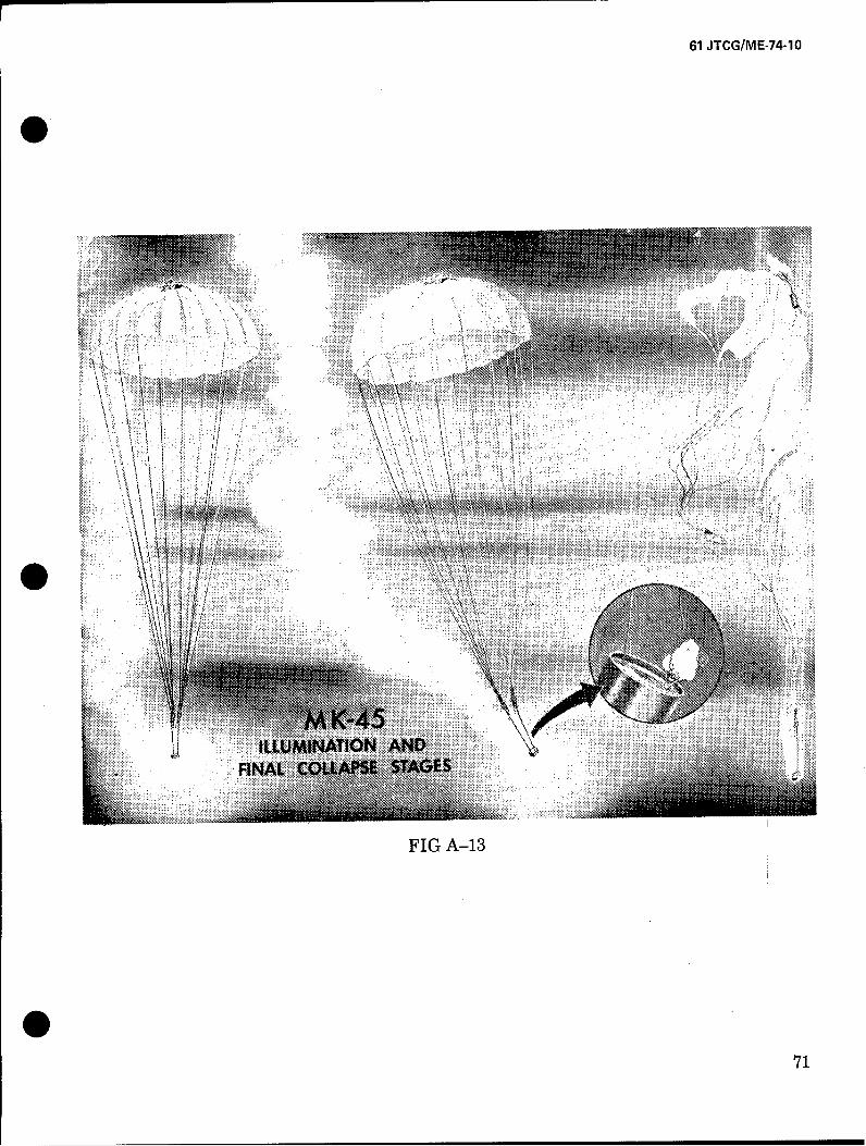
61 JTCG/ME-74-1O
N IT
......ILLUMINATION ANDFINAL COLPESAE
FIG A-13
71
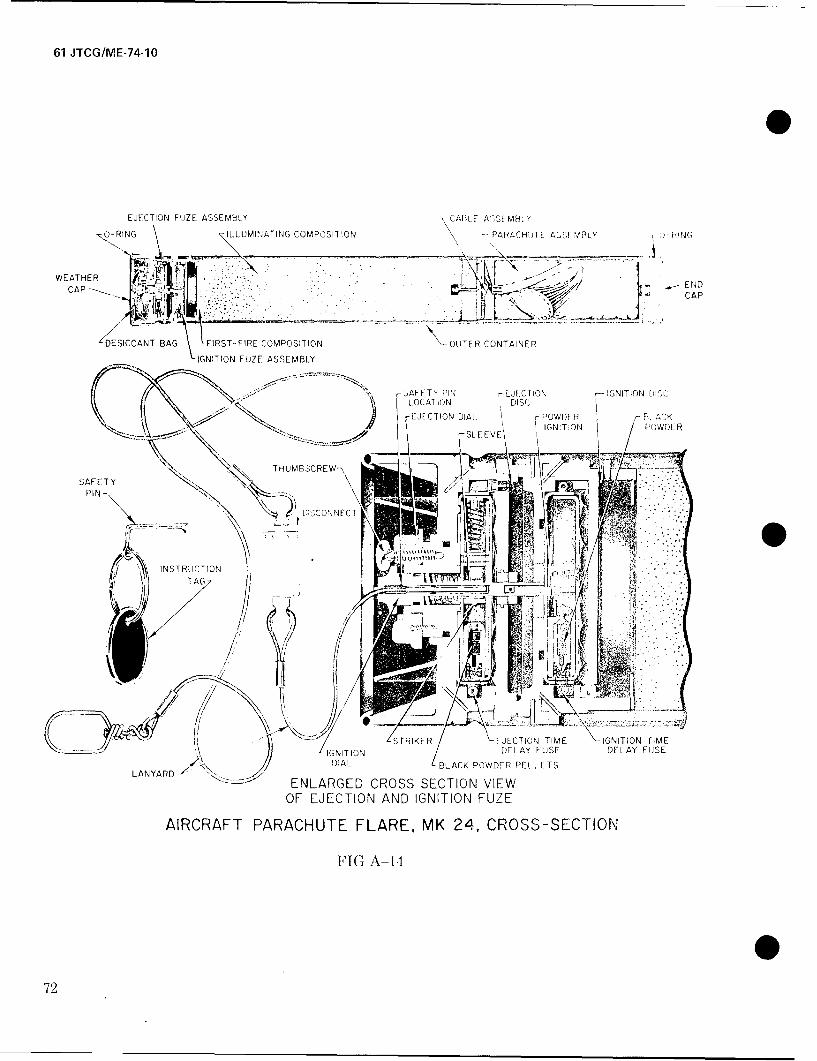
61 JTCG/ME-74-1O
EJECTION FUJZE ASSEIVULY ~;CAI3L ASU EMBLý
pý-RIN NLUINTN COMPOSITION PARACHi)TE AUCCI/DI Y O-ING
WEATHER. .1 _
CAP ___ - -- CAP
/DESICCANT BAG FIRST-FIRE COMPOSITION OUTER CONTAINER
IGNITION FUZE ASSEMBLY
LOCATIONDISC
N ~TH-UMBSCREW--\SAFETY
PIN F [IUSCONNEC rTi~
INSTRUCTO __ ,
SýT R I KER EJECTION TIME \-GNITION TME\.IGNITION DELAY FUSE DFLAY FUSE
LANARDDIAL BLACK POWDER PELLETS
-- ENLARGED CROSS SECTION VIEWOF EJECTION AND IGNITION FUZE
AIRCRAFT PARACHUTE FLARE, MVK 24, CROSS-SECTION
FIG A-i-I
72
61 JTCG/ME-74-10
The desiccant bag is utilized to protect the fuze assemblies from moisture during shipment and* storage. It is located between the weather cap and the ejection fuze.
Also located between the weather cap and the ejection fuze is the lanyard assembly, whichconsists of two flexible, stainless steel cables (7 and 27 inches long, respectively) joined by adisconnect which releases between 55 and 75 pounds force.
Located at the forward end of the round, directly below the fuze dials, is the ejection fuzeassembly. Consisting of an ejection plunger and housing assembly, a delay fuze line and anejection charge assembly. It controls the candle and parachute ejection from the outer case.The ejection fuze dial is yellow with a black arrow which points to the outer ring of blackfigures on the fuze dial. It contains a thumbscrew, for dial locking, which passes through theyellow ejection fuze setting dial. The ejection fuze has a range from 5 to 30 seconds in fivesecond intervals.
Controlling candle ignition is the ignition fuze assembly, which is located directly below theejection fuze assembly. It consists of an ignition plunger and housing assembly, a delay fuze line,and an ignition composition assembly. The ignition fuze setting dial is painted black witha white arrow which points to an inner ring of white figures orn a black background on thefuze dial. A spring steel safety pin is inserted through the bottom of the dial. The ignitionfuze has a range from 10 to 30 seconds in five second intervals.
The candle assembly, located directly behind the ignition fuze, consists of a kraft paper tubefilled with an illuminant composition of magnesium, sodium nitrate and epoxy binder. Thereis 16.2 pounds of composition contained in every candle. A wooden block is stapled inside theaft section of the candle tube for suspension system attachment.
The parachute assembly consists of a 16 foot diameter flat circular parachute in a split card-board container. It is located directly to the rear of the candle assembly.
The cable assembly connects the parachute assembly with the wooden block in the candleassembly.
The compression pad, located between the parachute and the end cap, assures that all com-ponent manufacturing tolerances are taken up and all assemblies are held firmly in place.
Crimped to the aft end of the outer container is the aluminum end cap which, by means of an"O"-Ring seals the aft end of the round.
b. Functioning. When the flare is launched from the aircraft, it falls free for a distance equalto the length of the lanyard. When the pull of the flare on the lanyard reaches 12 pounds, thelanyard raises a sleeve in the ejection fuze. This permits a spring-loaded striker to hit thepercussion primer, which initiates the fuze cord according to the ejection fuze time setting.During this time the force on the lanyard becomes large enough (55 to 75 pounds) to dis-connect the flare from its static line. At the end of the preset delay, the ejection delay fuzeignites the ejection charge disc. Gases from the burning ejection charge disc forcibly eject (inorder) the end cap, the compression pad, the parachute assembly with split cardboard con-
73
61 JTCG/ME-74-10
tainer, the candle assembly and the ignition fuze assembly. The ejection charge also propagatesto an ignition charge on the ignition fuze assembly.
Upon ejection, the parachute opens and suspends the candle with the ignition fuze assemblyattached. The ignition fuze burns for the time preset on the dial and ignites a gasless ignitionpowder. This powder in turn ignites the candle which then burns off the ignition fuze assemblyand continues to burn for the appropriate burning time.
6. ATTACK AIRCRAFT PARACHUTE FLARE
a. Description. The Attack Aircraft Parachute Flare (Fig A-15) is 61.4 inches long, 8.00inches in diameter and weighs 103.6 pounds. The flare consists of nine major sub-assembliesor components; a thin aluminum case, an illuminant tamp-cast into and bonded to the case,an ignition system, a main support parachute, a decelerator drogue parachute (with supportline and five-second delay pyrotechnic reefing line center), a mechanical drogue releasetime assembly, an aerodynamic nose cone, a cast aluminum hardback and a set of fouraerodynamically stabilizing fins.
The forward end of the flare utilizes the ogive nose cone to reduce aerodynamic drag duringaircraft carry. The nose cone is hollow and contains two pressure relief ports. Attached to theaft end are four fins which provide aerodynamic stability during aircraft separation andfree fall. The illuminant candle, ignition system, main parachute, drogue parachute and reefingline cutter are all contained within the eight inch diameter cylindrical aluminum case. Thecast aluminum hardback is attached to the flare case by two band type coupler clamps, oneat the ignition housing and one at the bulkhead between the candle and parachute compart-ments.
The main parachute support cables and the drogue parachute support line are attached tothe case bulkhead. The aft end of the flare case is closed by a plastic cover which houses, andis released by, the mechanical timer and related fuze mechanisms. The flare candle compart-ment is lined with an asbestos insulation material and a mastic liner, prior to tamp castingthe illuminant composition (magnesium, sodium nitrate and polyester binder). The candleend of the case is sealed by an O-ring in the igniter housing and the parachute compartmentis sealed by an O-ring in the timer housing.
b. Functioning (Fig A-16). As the Attack Flare is released from the aircraft, the armingwire is pulled and the preset timer is initiated. When the flare has fallen the desired distance(500 to 9,000 feet), the timer and cover are released and ejected (by spring) from the aft endof the flare case. The ejecting timer pulls out the drogue parachute which is attached to theflare bulkhead.
The drogue parachute opening shock initiates a five second delay, which when burned throughactivates the reefing line cutter, releasing the drogue parachute from the bullkhead. Thedrogue parachute then pulls ou the main parachute. The shock of the main parachute deploy-ment causes flare ignition. The nose cone and igniter assembly are consumed during the initialperiod of candle burning. An explosive bolt is initiated 20 seconds prior to candle burnout anddumps the main parachute.
74
61 JTCG/ME-74-1O
u-J
UU
0 -j
Urn o
U <
00C-))
UU
00< 75
61 JTCG/ME-74-1O
IF k
r cc 2 zH0H WU-J 00J W m
>ZU J- C)w :D
Fx z- ~ WW HoW~F -W D 0 cr
V)~ Z) D) C - ! : 2m""i u-~ w-i 020 W <
[Sf <0 W2m Lj2: c
<w W 0 00c~~ H U~z < 0
uj u-
(DQ 2E wOJ U Dw 0 U)u w 2! n-
2! LJ D >- _ - D
Q- <D - <2 HU-N
«0 -J H WLILl C 2c L- 2~0>
0 <C < C/) <2-cx 0) U i W/<0<<C-0 1< J Lu 2 L< W-cc
OUJ
WwuIw,0 w2 20-
< I I 2 LJ2! -L
U-N _j< j 0 0 W Q coH Hc
0 -U~ O M< 2iLW -jD- n0-0 0 0 0LLw >-<L
61 JTCG/ME-74-10
7. MLU-32A/B99 AIRCRAFT FLARE
a. Description. The MLU-32A Aircraft Flare (Fig A-17) is 63 inches long, 8.38 inches indiameter and weighs 147 pounds. The flare consists of an outer case and hardback assembly,a timer assembly, a balloon, a heat generator and the flare's candle. The outer case and hardbackassembly consists of a cylindrical container and a tapered nose section, both made of 0.07 inchaluminum. A strongback is bonded with epoxy to the container and further secured to it bytwo steel straps. Two fixed suspension lugs, spaced 14 inches apart, are installed in the strong-back. This item is only capable of being launched from standard 14 inch aircraft bomb racksmounted externally. There are no internal or external aircraft dispensers that will hold theMLU-32A Aircraft Flare.
Located at the forward end of the strongback, the timer assembly can be set at 2 seconds, 5seconds and then at 5 second intervals up to 25 seconds. The timer's arming wire'is routedthrough a retainer guide, which is attached to the strongback, and then inserted in the timer.A streamer assembly, which is a safety device that is removed before flight, is installed in boththe timer and the nose cone's clamp. Internally, the timer assembly consists of a mechanicaltimer, a striker assembly, a stab primer and an initiation charge.: I
The balloon assembly' 4nlsists of the balloon itself, a drag parachute, a cloth deployment bagand a "Y"-bridle. The balloon assembly and its heat generator constitute the suspensionsystem for this flare." /
Contained within the 'cylindrical container is the candle assembly. Its composition is of themagnesium, sodium nitrate and binder type. The candle also provides for 30 seconds ofemitting a red light at the termination of candle burning. There is a descent system whichdeflates the balloon at candle burnout.
b. Functioning (Fig A-18). Ejection of the flare pulls the arming wire from the timer, whichwill then function after the preset delay has run out. The timer initiates a shaped charge thatsevers the nose cone clamp. The nose cone is then spring-ejected, releasing the drogue para-chute. Upon opening, the drogue parachute, actuates the line cutter and initiates the pyro-technic delay train of the vent and self destruct system. After approximately 3 seconds, acloth deployment bag is stripped off of the balloon. The balloon deploys and is filled withram air through its perimeter inflation ports. The "Y"-bridle is pulled taut by the balloonexpansion and mechanically actuates the candle igniter. The candle ignition system simul-taneously ignites the heat generator and the candle. The candle quickly burns through thefuzeable joint, tips over, and falls downward until it is suspended approximately 20 feet belowthe balloon by the energy-absorbing cable. The hot gases from the heat generator quicklyarrest the balloons descent. After the candle burns for approximately 4 minutes, the ventfunctions to control the descent rate. This is necessary to release the buildup of hot gasses inthe balloon, which would otherwise cause the flare to rise. Thirty seconds prior to burnout,the candle light turns red. The emitted red light acts as a burnout warning to those utilizingthe flare. At this point, the self-destruct system cuts the balloon top, which completely deflatesthe balloon and allows the flare remnants to descend rapidly to the ground.
77
61 JTCGIME-74-1O
7 06
Q- (
LAJ z
U~ U
g LA
0 0
Li-Jn IL>1 0
0 - V
9-
m~10I d~
o j(
CI - L J 0
U_ 078z
61 JTCG/ME-74-1O
LU SM
0< 3
LU uiSM4
LU L
N.L
007
61 JTCG/ME-74-10
APPENDIX B
FLARE QUESTIONNAIRE
A. Pilots Questionnaire: All pilots did not answer every question; therefore, the total numberof responses to some questions may appear incorrect. Eighteen strike pilots completed thisquestionnaire.
LUU-2/B FLARE QUESTIONNAIRE
The purpose of this questionnaire is to determine which flare (MK-24 or LUU-2/B) ismost effective for night strike operations. Your answers may have a direct impact on whichflare will be bought for Fiscal Year 71, so please consider each question carefully. The timermechanisms in the flares are different; however, an attempt will be made to ignite the flaresover the target with the same burnout altitudes so that your comparison will be more valid.
(Circle the Appropriate Answer)
1. (Q) Which flare best enabled you to locate and attack the target on the first pass?
LUU-2/B--3
MK-24-9
No Difference-6
2. (Q) Did you observe any glare from either the LUUJ-2/B or MK-24?
Yes-ll
No-7
If yes, which flare?
MK-24-6
LUU-2/B-0
Both-5
If yes, did the glare affect your ability to locate and attack the target?
Yes-2
No-9
3. (Q) If weather conditions such as haze, smoke, fog, or light rain (Circle those applicable)were present,
Haze-3
Smoke--
Both-5
None-6
80
61 JTCG/ME-74-10
which flare provided the best illumination?
MK-24-5
LUU-2/B--4
No Difference-3
4. (Q) Did you observe flickering of the light from either the LUU-2/B or MK-24 flare?
Yes-8
No-10
If yes, which flare?
MK-24--5
LUU-2/B-2
Both-1
If yes, did the flickering affect your ability to locate and attack the target?
Major effect-O
Minor effect-i
No effect-7
5. (Q) The LUU-2/B flare burns approximately two minutes longer than the MK-24flare. Did this additional burn time improve your ability to conduct a greater number ofeffective passes against the target?
Yes-14
No-4
6. (Q) How do you rate the LUU-2/B burn duration?
Adequate-12
Inadequate-0
More than adequate-6
If inadequate, indicate the recommended burn time which you believe would improvethe attack mission. - - minutes.
Not applicable
7. At the end of full flare burning time, the LUUJ-2/B flare parachute is dumped, causingthe burned-out flare to fall to the ground. (Q) Compared to the MK-24 flare which doesnot spill its parachute, how do you rate the dump feature of the LUU-2/B flare?
81
61 JTCG/ME-74-10
Desirable-13
Undesirable-2
Not observed-3
If undesirable, explain what effect this feature would have on the mission.
Two pilots felt that they could not work under a flare if they didn't know whenit would dump. It is not standard practice, however, for strike aircraft to fly under flares,because of the danger of presenting a good target to ground fire.
8. (Q) Which flare do you consider most effective for night strike operations?
MK-24-4
LUU-2/B--4
Both are equally effective-9
Not enough observed-1
9. Additional comments: (Be specific in your remarks about the LUU-2/B flare, as torecommended operational improvements or existing deficiencies of those flares which youobserved).
a. A common comment was that the LUU-2/B "seems to flatten out the terrain features.Vertical development is not as nticeable as with the MK-24."
b. Several pilots said that the wind carried the LUU-2/B away from the target beforeburn-out, wasting the longer burn.
c. Several pilots found that they liked the LUU-2/B flare better as they gained experience
with it.
10. Type Aircraft Crew Position SEA Tour Flare Operations Experience
The pilots responding flew A-i, OV-10, T-28, and A-37 aircraft. Fourteen of these pilotsand copilots had SEA experience. Four had completed two tours. Thirteen had flare operationsexperience.
B. Flare Handlers Questionnaire:
LUU-2/B FLARE QUESTIONNAIRE
The purpose of this questionnaire is to examine the flare loading and handling, timer setting,and launch characteristics of the LUU-2/B flare. Your answers will have a direct effect onwhich flare will be bought for Fiscal Year 71, so please consider each question carefully.
82
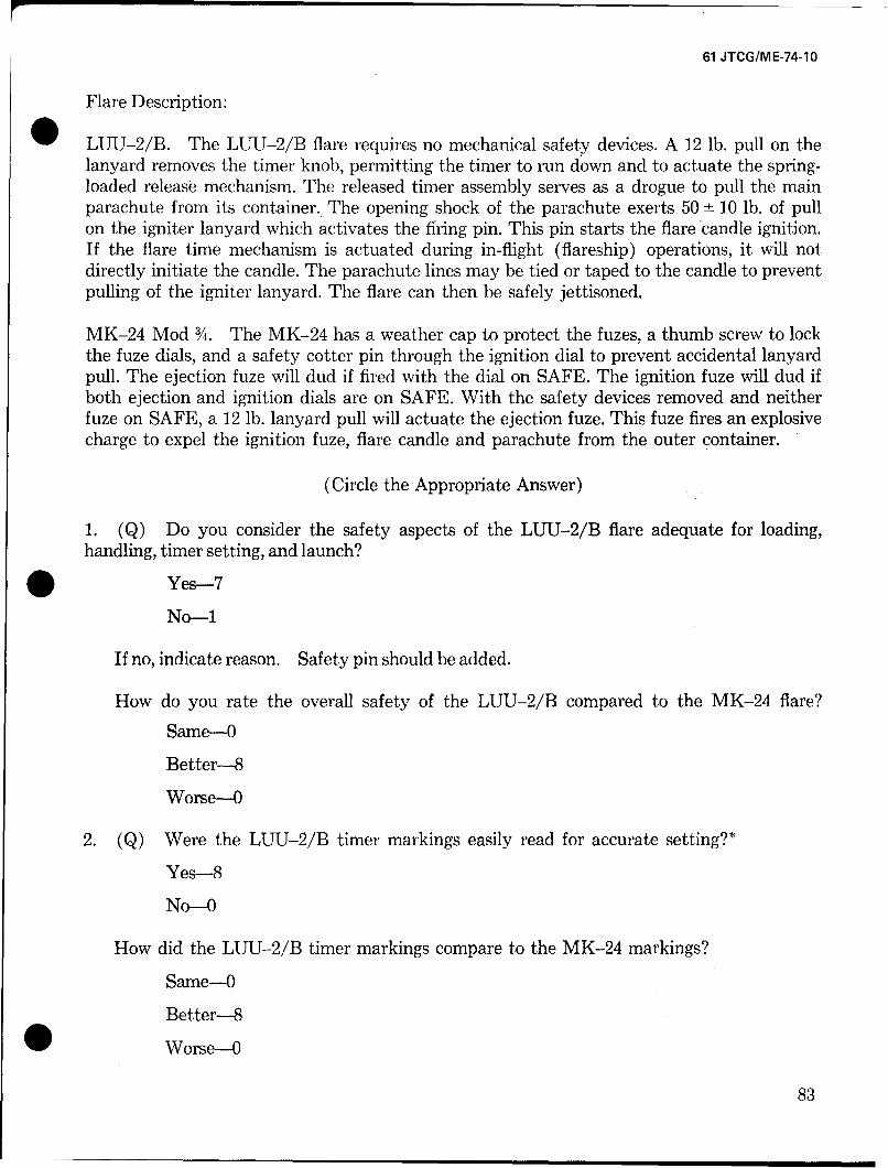
61 JTCG/ME-74-10
Flare Description:
LUU-2/B. The LUU-2/B flare requires no mechanical safety devices. A 12 lb. pull on thelanyard removes the timer knob, permitting the timer to run down and to actuate the spring-loaded release mechanism. The released timer assembly serves as a drogue to pull the mainparachute from its container. The opening shock of the parachute exerts 50 ± 10 lb. of pullon the igniter lanyard which activates the firing pin. This pin starts the flare candle ignition.If the flare time mechanism is actuated during in-flight (flareship) operations, it will notdirectly initiate the candle. The parachute lines may be tied or taped to the candle to preventpulling of the igniter lanyard. The flare can then be safely jettisoned.
MK-24 Mod ./4. The MK-24 has a weather cap to protect the fuzes, a thumb screw to lockthe fuze dials, and a safety cotter pin through the ignition dial to prevent accidental lanyardpull. The ejection fuze will dud if fired with the dial on SAFE. The ignition fuze will dud ifboth ejection and ignition dials are on SAFE. With the safety devices removed and neitherfuze on SAFE, a 12 lb. lanyard pull will actuate the ejection fuze. This fuze fires an explosivecharge to expel the ignition fuze, flare candle and parachute from the outer container.
(Circle the Appropriate Answer)
1. (Q) Do you consider the safety aspects of the LUU-2/B flare adequate for loading,handling, timer setting, and launch?
Yes-7
No--1
If no, indicate reason. Safety pin should be added.
How do you rate the overall safety of the LUU-2/B compared to the MK-24 flare?
Same--O
Better-8
Worse-O
2. (Q) Were the LUU-2/B timer markings easily read for accurate setting?*
Yes-8
No-O
How did the LUU-2/B timer markings compare to the MK-24 markings?
Same-O
Better-8
Worse-0
83
61 JTCG/ME-74-10
3. (Q) Do you consider the addition of a lanyard cotter pin necessary to prevent inadvertenttimer actuation during the LUU-2/B handling and loading?
Yes-2
No-6
4. Please make specific, detailed comments on deficiencies noted and your recommendationsfor improvement.
One flare handler commented that the drogue strip made recovery of the lanyard alittle difficult after manual launch from the "Raingutter."
* The white paint for the timer dial markings was missing from several flares, but the markingscould still be read with the use of a flashlight. The use of a flashlight is standard when settingMK-24 flares, but is made easier with the LUU-2/B because the settings are much easier tomake. The white paint is desirable, however.
84