Embed Size (px)
Citation preview
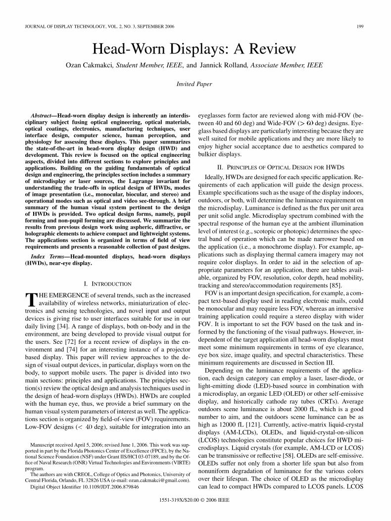
JOURNAL OF DISPLAY TECHNOLOGY, VOL. 2, NO. 3, SEPTEMBER 2006 199
Head-Worn Displays: A ReviewOzan Cakmakci, Student Member, IEEE, and Jannick Rolland, Associate Member, IEEE
Invited Paper
Abstract—Head-worn display design is inherently an interdis-ciplinary subject fusing optical engineering, optical materials,optical coatings, electronics, manufacturing techniques, userinterface design, computer science, human perception, andphysiology for assessing these displays. This paper summarizesthe state-of-the-art in head-worn display design (HWD) anddevelopment. This review is focused on the optical engineeringaspects, divided into different sections to explore principles andapplications. Building on the guiding fundamentals of opticaldesign and engineering, the principles section includes a summaryof microdisplay or laser sources, the Lagrange invariant forunderstanding the trade-offs in optical design of HWDs, modesof image presentation (i.e., monocular, biocular, and stereo) andoperational modes such as optical and video see-through. A briefsummary of the human visual system pertinent to the designof HWDs is provided. Two optical design forms, namely, pupilforming and non-pupil forming are discussed. We summarize theresults from previous design work using aspheric, diffractive, orholographic elements to achieve compact and lightweight systems.The applications section is organized in terms of field of viewrequirements and presents a reasonable collection of past designs.
Index Terms—Head-mounted displays, head-worn displays(HWDs), near-eye display.
I. INTRODUCTION
THE EMERGENCE of several trends, such as the increasedavailability of wireless networks, miniaturization of elec-
tronics and sensing technologies, and novel input and outputdevices is giving rise to user interfaces suitable for use in ourdaily living [34]. A range of displays, both on-body and in theenvironment, are being developed to provide visual output forthe users. See [72] for a recent review of displays in the en-vironment and [74] for an interesting instance of a projectorbased display. This paper will review approaches to the de-sign of visual output devices, in particular, displays worn on thebody, to support mobile users. The paper is divided into twomain sections: principles and applications. The principles sec-tion(s) review the optical design and analysis techniques used inthe design of head-worn displays (HWDs). HWDs are coupledwith the human eye, thus, we provide a brief summary on thehuman visual system parameters of interest as well. The applica-tions section is organized by field-of-view (FOV) requirements.Low-FOV designs ( deg), suitable for integration into an
Manuscript received April 5, 2006; revised June 1, 2006. This work was sup-ported in part by the Florida Photonics Center of Excellence (FPCE), by the Na-tional Science Foundation (NSF) under Grant IIS/HCI 03-07189, and by the Of-fice of Naval Research (ONR) Virtual Technologies and Environments (VIRTE)program.
The authors are with CREOL, College of Optics and Photonics, University ofCentral Florida, Orlando, FL 32826 USA (e-mail: [email protected]).
Digital Object Identifier 10.1109/JDT.2006.879846
eyeglasses form factor are reviewed along with mid-FOV (be-tween 40 and 60 deg) and Wide-FOV ( deg) designs. Eye-glass based displays are particularly interesting because they arewell suited for mobile applications and they are more likely toenjoy higher social acceptance due to aesthetics compared tobulkier displays.
II. PRINCIPLES OF OPTICAL DESIGN FOR HWDS
Ideally, HWDs are designed for each specific application. Re-quirements of each application will guide the design process.Example specifications such as the usage of the display indoors,outdoors, or both, will determine the luminance requirement onthe microdisplay. Luminance is defined as the flux per unit areaper unit solid angle. Microdisplay spectrum combined with thespectral response of the human eye at the ambient illuminationlevel of interest (e.g., scotopic or photopic) determines the spec-tral band of operation which can be made narrower based onthe application (i.e., a monochrome display). For example, ap-plications such as displaying thermal camera imagery may notrequire color displays. In order to aid in the selection of ap-propriate parameters for an application, there are tables avail-able, organized by FOV, resolution, color depth, head mobility,tracking and stereo/accommodation requirements [85].
FOV is an important design specification, for example, a com-pact text-based display used in reading electronic mails, couldbe monocular and may require less FOV, whereas an immersivetraining application could require a stereo display with widerFOV. It is important to set the FOV based on the task and in-formed by the functioning of the visual pathways. However, in-dependent of the target application all head-worn displays mustmeet some minimum requirements in terms of eye clearance,eye box size, image quality, and spectral characteristics. Theseminimum requirements are discussed in Section III.
Depending on the luminance requirements of the applica-tion, each design category can employ a laser, laser-diode, orlight-emitting diode (LED)-based source in combination witha microdisplay, an organic LED (OLED) or other self-emissivedisplay, and historically cathode ray tubes (CRTs). Averageoutdoors scene luminance is about 2000 fL, which is a goodnumber to aim, and the outdoors scene luminance can be ashigh as 12000 fL [121]. Currently, active-matrix liquid-crystaldisplays (AM-LCDs), OLEDs, and liquid-crystal-on-silicon(LCOS) technologies constitute popular choices for HWD mi-crodisplays. Liquid crystals (for example, AM-LCD or LCOS)can be transmissive or reflective [58]. OLEDs are self-emissive.OLEDs suffer not only from a shorter life span but also fromnonuniform degradation of luminance for the various colorsover their lifespan. The choice of OLED as the microdisplaycan lead to compact HWDs compared to LCOS panels. LCOS
1551-319X/$20.00 © 2006 IEEE
200 JOURNAL OF DISPLAY TECHNOLOGY, VOL. 2, NO. 3, SEPTEMBER 2006
panels typically require illumination optics. The trade-off inusing illumination optics is brightness versus compactness.OLED can be considered relatively dim compared to optimizedillumination for LCOS. Compact LCOS illumination systemsare an active research and optical engineering area. LED-basedillumination schemes constitute one of the directions in com-pact LCOS illumination system development. The promiseof LEDs in LCOS illumination are of a long lifespan, smallphysical size, and low operating voltages. LEDs can operate insequential mode emitting red, green, and blue light at a specifictime instance synchronized with the display. LED luminanceis also improving and becoming suitable for low light outputsystems (i.e., on the order of 50 lm/W per LED). System levelconsiderations, such as optical filters, integrators, polarizationcomponents, and projection lenses are discussed in [171], andsome of these considerations apply to HWD design as well.Ferrin has compiled a more complete list of microdisplayssuitable for HWD applications [83]. An in-depth discussion ofmicrodisplay technology that covers the structure and perfor-mance of microdisplays can be found in [104].
Laser sources have been employed in scanning displays.Typically, laser-based sources have been brighter comparedto their microdisplay counterparts. The perceived brightnessis a function of both the laser dwell time (i.e., time allocatedfor the laser beam at each pixel) and the source luminance.Laser-based sources can also be divided into high and lowpower sources. Laser-based displays based on high power lasersources have been demonstrated with 1500 fL luminance formilitary applications, however such systems are not portableand the demonstrators have been monochromatic. Laser-baseddisplays based on laser-diodes with luminance up to 900 fLhave been demonstrated for medical, aerospace, and industrialapplications. An alternative to higher luminance sources isto dim the light from the scene through electrochromic orphotochromic mechanisms, see [3] for an example and [43] fora review of organic and polymeric electrochromic materials.
Design trade-offs in HWDs related to the exit pupil, or eyebox size which defines the limits of user eye position from whichthe entire display is visible, and the FOV can be understood byapplying the Lagrange invariant. The derivation of the Lagrangeinvariant can be found in many classical geometrical optics text-books, see, for example, [20]. The Lagrange invariant, axiomat-ically stated and applied to the pupils, can be written as follows:
(1)
where represents the semi field of view at the entrance pupil,is the radius of the pupil in object space, is the refrac-
tive index in the object space, is the chief ray angle at the exitpupil, is the radius of the exit pupil, and is the refrac-tive index in the image space. Using (1), for a fixed value of theLagrange invariant, the FOV in image space is inversely propor-tional to the exit pupil height. A drawback of a small exit pupilis that the eye naturally moves within the display, vignetting andin a worse case scenario 100% vignetting may occur, yielding ablackout of the image. In Section IV, we will relate this propertyto the design of retinal scanning displays.
The light is emitted from a microdisplay, then collected bythe optics within its numerical aperture, before being redis-
tributed onto an image plane through the imaging process. Thenumerical aperture, or equivalently the of the optics, setsthe amount of light flux contributing to the imaging process.The conservation of light flux together with the Lagrangeinvariant now applied to the microdisplay and the image planeyield conservation of luminance. Therefore, according to theLagrange invariant, the luminance of the virtual image formedthrough a HWD will be constant. The statement of constantluminance may be counter-intuitive; the common misconcep-tion is to reason that because the virtual image is magnified,the luminance would decrease. However, we need to considerboth the cone angle and the magnified image plane area andremember that their product is constant.
Another fundamental trade-off in HWDs exists between theFOV and the resolution. This trade-off exists because a function-ality of the HWD optics is to spread the pixels on the microdis-play across the FOV. Thus as the FOV is increased, the numberof pixels per degree decreases. Approaches to overcoming thistrade-off has been to use a high resolution area of interest [105],[106], resort to partial binocular overlap [82] or implement op-tical tiling [38].
HWDs can be monocular where a single image is presentedto a single eye, biocular (see [13] for a review of biocular op-tics design) where the same image is presented to both eyes, orbinocular where two distinct images are presented to each eye.There are optical design and perceptual issues associated witheach mode.
HWDs can be designed in optical see-through, opaque,or video see-through modes. Optical see-through systemstypically make use of beamsplitters to combine the computergenerated objects with the real-world. In video see-throughmode video cameras capture the scene which is combinedwith computer-generated imagery. In this mode the user viewsthe world through the displays, therefore does not get a directview of the world. Rolland and Fuchs compare the opticalsee-through and video see-through modes in [34] and con-clude that the most important issues are latency, occlusion, thefidelity of the real-world view, and user acceptance. Histor-ically, occlusion has been technically easier to achieve withvideo see-through display even though optical approaches toocclusion, both transmissive [66], [135] and reflective [136],[137], are actively pursued. A compact solution to the occlusioncapable HWDs remains a research challenge.
View point offset is also a critical issue in systems that cap-ture the real-world with optical systems before presented to theeyes. Magnitude of the viewpoint offset has been found to im-pact the sensorimotor adaptation [118]. Orthoscopic displayswhich do not introduce a view-point offset have been built fora modest FOV [64]. In [64] the FOV was 26 19.6 degrees.Biocca and Rolland comment that it is difficult, if not impos-sible, for video-based see-through HWDs to perfectly match thenatural viewpoint of the user for wide FOV displays [118].
III. A BRIEF SUMMARY OF THE HUMAN VISUAL SYSTEM
PERTINENT TO THE DESIGN OF HWDS
In optical design of HWDs we characterize the human visualsystem in terms of its object space parameters and aim to de-liver a high quality image in the object space of the human eye.Designing in the object space means that we do not compensate

CAKMAKCI AND ROLLAND: HEAD-WORN DISPLAYS: A REVIEW 201
for the aberrations of the human eye or rely on the results fromthe encoding and processing that occurs starting at the retinaand going through the optical nerve, the lateral geniculate body,the primary visual cortex (V1), and the extrastriate areas [140].However, a basic understanding of aberration tolerances of theeye and the influence of accommodation is useful in designingHWDs.
In this section, we shall briefly summarize some of the ob-ject space parameters of primary interest for designing HWDs.The functional primary parameters of interest are the variationin pupil size under various levels of illumination, the depth offield, the smallest feature size that the human eye can resolve,e.g., the resolution of the eye, the spectral characteristics of thelight absorbed by the cones in the retina, and the aberration tol-erances of the human eye. Binocular properties of the visualsystem which are of interest include the inter-pupillary distanceand the stereoacuity which is the threshold discrimination ofdepth from very small disparities [59]. Finally, a summary ofperceptual issues in HWDs will be provided in this Section.
The field of view of the human eye is 200 deg by 130 deg witha 120-deg overlap [121]. The lens of the eye is a gradient indexelement with a higher index at the center. Front focal length ofthe eye is about 17 mm and the rear focal length is about 23 mm,the difference is due to the fact that the refractive index of thevitreous material is 1.336 [30]. Most of the optical power is pro-vided by the cornea. Depending on age, the lens can contribute a10–diopter optical power change in order to focus on closer ob-jects. There exist several optical models of the human eye, someof the more schematic but still useful models of the eye are:the reduced eye (single surface), the simplified schematic eye(three refractive surfaces), and the unaccommodated schematiceye (four refractive surfaces) [24]. The first-order parameters ofinterest such as the location and size of the pupil, and the centerof rotation are the same across these models; therefore, they areequivalent for the design of HWDs.
The pupil is the optical aperture of the human eye which canchange its size through dilation and contraction of the musclesthat control the iris. The diameter of the pupil changes from 2mm under sunlight to about 8 mm in the dark. A recent study,under ambient hospital lighting conditions (the authors do notquantify these ambient conditions), was done in 300 healthyparticipants and the mean resting pupil size was found to be 4.11mm [126]. The normal eye is considered to be near-diffractionlimited for a 2 mm pupil. The entrance pupil location is about 3mm from the vertex of the cornea and resides behind the cornea[42]. Ogle and Schwartz [123] quantify that the depth of fielddecreases in steps of 0.12 diopters as the pupil size increase insteps of one mm.
The classical approach to determining the resolution of theeye has been the application of the Nyquist frequency to theanatomical data on the spacing of the cone mosaic. Curcio etal. studied the spatial density of cones and rods in eight humanretinas obtained from 7 individuals between 27 and 44 years ofage. An average of the center to center spacing of the cones re-ported in [29] yields 2.5 m and can be converted to a visualangle of 0.5 arcmins. However, we should note that there existsstudies on the cone spacing and the resolution limit reportingthat, under certain conditions, observers can see fine patterns atthe correct orientation when viewing interference fringes with
spatial frequencies as much as about 1.5 times higher than thenominal Nyquist frequency of the underlying cone mosaic [28].Currently, the trend in HWD design is to aim for 1 arcmins ofvisual acuity. We should also note that the higher visual acuityoccurs within the fovea region, spanning roughly 5 deg aroundthe optical axis of the eye. Finally, dynamical visual acuity [32],while challenging to measure, is of critical importance to HWDdesign. It is well known that the human visual system summatessignals over a time period of about 120 ms. In quantifying visualperformance for moving factors, a compounding factor is mo-tion smear. Burr reports that if the target is exposed long enoughthe amount of smear is far less than may be expected [172].
Stray light, caused by ocular scattering, affects the contrastspecification of an HWD [76]. De Wit shows that for a 24 18deg display, the maximum achievable contrast for a 4 4checkerboard image is approximately 80:1. This is calculatedby convolving the ideal image with the point spread function ofthe eye. Hasenauer and Kunick analyzed the impact of veilingglare in an HWD system and offered techniques to isolate thesources of stray light and minimize their impact in the design[107].
Spectrally, light is transmitted starting at about 400 nm andup to 1400 nm through the ocular media [25]. However, only aselected portion of these wavelengths are absorbed by the cones,depending on the level of illumination. Based on the Commis-sion International de L’Eclairage (CIE) curve, we can considerthe photopic visible spectrum to span from 400 to 700 nm. Thephotopic response curve peaks at 555 nm. Based on the photopicresponse curve, optical designers choose a spectral weightingscheme and incorporate it as a meaningful factor throughout theoptimization process.
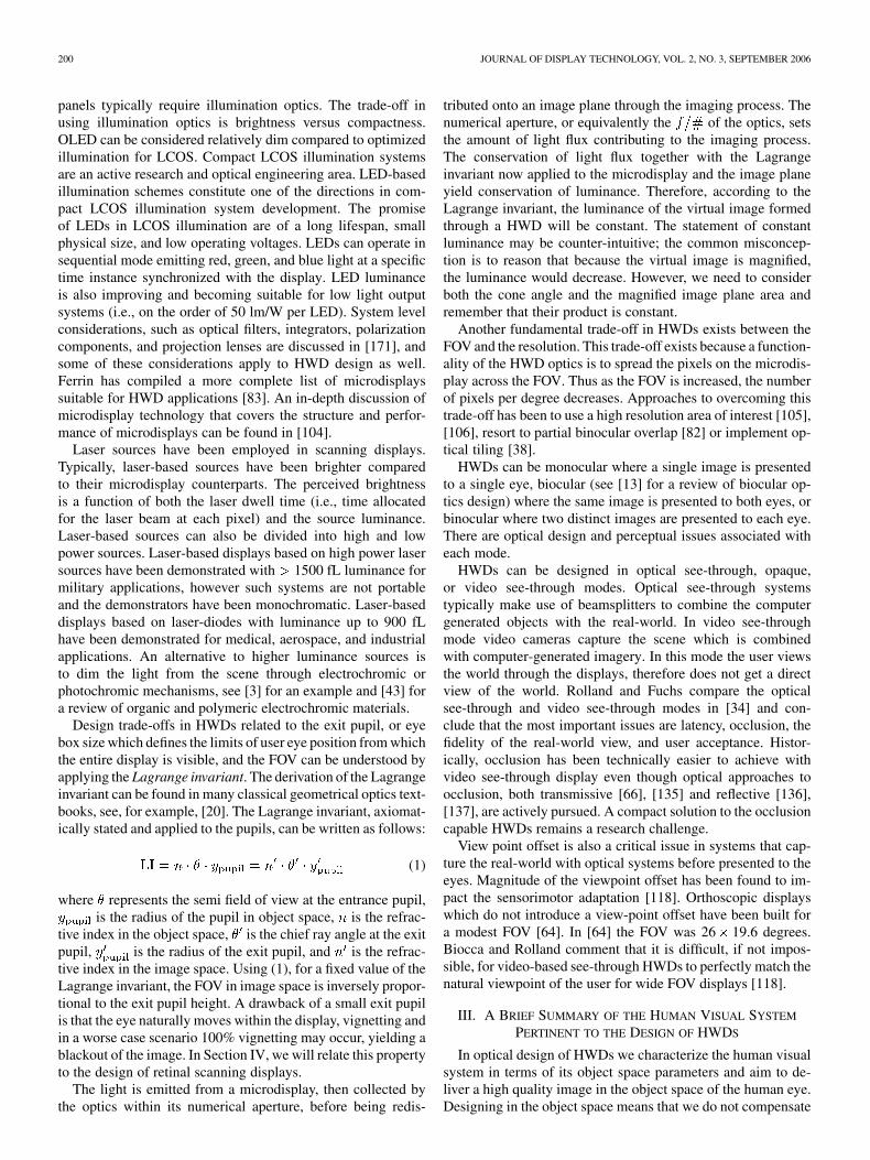
Burton and Haig [47] simulated the effects of Seidel aber-rations (defocus, spherical aberration, astigmatism and coma)on four images and determined the tolerances of the human vi-sual system to different levels and combinations of the aberra-tion types by a forced-choice discrimination task [50]. The basicidea in the experiment is to convolve targets with aberrated pointspread functions having varying levels of aberration and to com-pare the aberrated image against the original in a controlled set-ting to quantify the level of just-noticeable differences betweenthe images. Measurements of aberration tolerances were per-formed with 2 mm pupils. A summary of the averaged peak tovalley aberration thresholds for 60%, 75%, and 90% discrimina-tion probabilities, across four targets and two observers is givenin Table I.
In terms of chromatic aberrations of the eye, Rodgers cal-culated the chromatic aberrations of the eye by combining thephotopic response curve with the chromatic aberration curveof the eye and found an error of for a pupil of 2.4 mm[101]. Hence, the chromatic aberration of the eye under pho-topic conditions, for an average outdoor scene, is rather benign.Mouroulis et al. [162] reported that the 2.5 arcmins recommen-dation represents a measurable drop in performance and con-stitutes a realistic tolerance for the transverse chromatic aberra-tion.
Binocular properties of the visual system are important forall modes of operation monocular, biocular, and binocular dis-plays. Briefly, with monocular displays the visual system inmany cases may respond with binocular rivalry, a perceptual
202 JOURNAL OF DISPLAY TECHNOLOGY, VOL. 2, NO. 3, SEPTEMBER 2006
TABLE IABERRATION THRESHOLDS IN THE FORM OF JUST-NOTICEABLE DIFFERENCES
LISTED IN TERMS OF PROBABILITY OF DISCRIMINATION
conflict when the two eyes receive very different stimulation.With biocular displays, the two eyes receive the same stimu-lation which would signal to the visual system that the scenecontains zero disparity throughout the visual field (which woulddilute the visual effect of any perspective depth cues present)[173]. See [51] for a discussion of binocular issues associatedwith the design of stereo displays. A review of human stere-opsis is provided by Patterson and Martin [59], readers inter-ested in depth perception in stereoscopic displays may also referto [119]. Patterson organizes his review around five functionaltopics that may be important for the design of stereoscopic dis-play systems: geometry of stereoscopic depth perception, visualpersistence, perceptual interaction among stereoscopic stimuli,neurophysiology of stereopsis, and theoretical considerations.Important concepts in stereopsis stem from the retinal positionsof images referred to as disparity. The horopter can be thoughtof as a baseline of zero disparity based on the retinal images,and can be defined geometrically (Vieth-Muller circle) or psy-chophysically [59]. In terms of the geometry of stereoscopicdepth perception, Patterson notes that the processing for pointsinside (crossed disparity) or outside (uncrossed disparity) of thehoropter is done by separate mechanisms [60]. The consequenceis that depth perception quality can be different for points re-siding in the crossed and uncrossed disparity regions. The smallarea slightly in front or behind the horopter is called the Panum’sfusional area. In terms of binocular fusion, fusion limits dependon the disparity magnitude. Fusion limits are given to be 10arcmins (e.g., small disparity), 2 deg (e.g., medium disparity)and 8 deg (e.g., high disparity). Beyond these limits, objectsmay be seen double (diplopic). The disparity limits of fusionare reported to covary directly with stimulus size or scale, andinversely with spatial frequency. The limit does not vary withcontrast. Vergence eye movements are known to improve therange of disparities that can be processed by the human visualsystem. Clinical tests carried at a distance of 40 cm with a fixed65 mm IPD assumption yield a stereoacuity between 20–40 arc-seconds [25] and stereoacuity can be as low as 8 arcseconds[59]. It is known that stereoacuity varies with luminance andspatial frequency [60]. Patterson found that high stereoacuityis obtained with high spatial frequencies and low temporal fre-quencies [174]. High stereoacuity is achived in the fovea re-
gion. Therefore, high quality depth discrimination over the vi-sual field requires eye movements [59]. The optical design con-sequence of supporting eye movements is to have either a largeexit pupil or eye tracking capability [166], [168]. The opticalconsequences of eye movements in visual instruments includefull or partial vignetting and was analyzed in [62]. In terms of vi-sual persistence, Patterson and Martin [59] recommend that fordisplays operating using the field sequential technique, longerdurations of 10 ms or higher would be expected to produce betterdepth perception due to greater binocular integration for eachchannel. Other trade-offs such as color smear will need to beinvestigated.
According to MIL-STD-1472C and the literature on the sta-tistics of IPD values including, the IPD adjustment range for abinocular HMD is recommended to be at least 50–78 mm. U.S.Air Force anthropologists measured the IPD of 4000 flying per-sonnel and the mean yielded 63.3 mm [114]. Self provides areview of optical tolerance limits for binocular displays [56].Based on the rather sparse data available in this field, recom-mendations of Self are based on studies of Gold [133] and Goldand Hyman [134]. Both of these studies are limited to no morethan four observers, hardly representative of a population asnoted by Self. Self recommended vertical misalignment of thetwo optical axes, horizontal misalignment of the two opticalaxes, rotational difference between the optical axes to not ex-ceed 3.4 arcmins. Self recommended that the tolerance for themagnification difference between the two images at the edge ofthe overlap area to not exceed 10 arcmins with a less than 3.4arcmins preferred value. Self recommended a luminance differ-ence tolerance between the two images to be less than 25% andpreferably less than 10%. Self recommended the collimation tol-erance shall be such that the optical distance to the displayedimage shall be between 100 m to .
Patterson, Winterbottom and Piece provided a comprehensivereview of perceptual issues in HMDs [122] which we shall sum-marize in this paragraph. Patterson organizes his review in fivesections: luminance and contrast and their effect on depth offield, dark focus and dark vergence, accommodation-vergencesynergy and its effect on perceptual constancy (e.g., size andspeed constancy), eye strain and discomfort, FOV and its rela-tionship to the functioning of different visual pathways, binoc-ular input and its relationship to visual suppression and headmovements.
In terms of luminance and contrast, as the luminance is in-creased, the pupil size reduces and the depth of field increases.The competing trend is that as the target resolution increases,depth of field decreases. Therefore, both the luminance level andthe target resolution should be considered when designing for aspecific depth of field value. Depth of field is a critical distancethat determines objects that appear in sharp focus. Depth of fieldshould be set appropriately so that the user can properly perceiveboth the computer generated imagery and the real objects lyingat the same depth. Under low levels of illumination or degradedstimulus conditions, the accommodation will rest around a 1 mvalue with some variation [124].
The human eye has evolved in such a way as to convergeand accommodate at the same point of interest as it saccadesacross the FOV. Monocular systems can present the magnifiedvirtual image of the microdisplay at a fixed distance from the

CAKMAKCI AND ROLLAND: HEAD-WORN DISPLAYS: A REVIEW 203
user and the information appears to reside on this single plane.The consequence is that the users can accommodate and con-verge on the plane of the virtual image which is consistent withthe accommodation and convergence mechanism of the humaneye. Stereo displays demand that the users focus on the planeof the virtual images formed by the optics and converge po-tentially at different depths away from that plane in order toperceive three dimensional. As a guideline, the human eye re-quires that accommodation and convergence match to within
0.1 of a diopter [36]. Accommodation and convergence con-flict is known to result in eye strain and discomfort. Moffitt re-ports a to be workable and a 0.5 diopteras the maximum level of mismatch [37]. If the accommoda-tion and convergence planes are further apart than the work-able mismatch, the eyes would converge to the correct locationto avoid diplopia and suffer from excessive blur as a trade-off.Multi-focal displays have been proposed to resolve the accom-modation-convergence conflict [38]. When the accommodativeresponse becomes a compromise between the stimulus and thedark focus value, size, depth and speed may be misperceived.Vergence seems to be valid down to 0.02 fL [127] and the ac-commodation seems to be valid down to between 2–100 fL[125]. In terms of the accommodation-vergence conflict, Pat-terson recommends that more research is necessary to determinethe exact tolerance limits.
Multi-focal planes could be based on non-moving parts. Theidea in multifocal planes is to construct a miniature 3-D dis-play, image the 3-D source into a volume perceived as contin-uous dictated by the limits of human visual acuity. The naturalquestion to ask is the minimum number of planes one wouldneed to cover the whole visual space. Rolland et al. has shownthat 14 planes can cover a focusing distance from 0.5 m to in-finity, under the assumptions of a 4-mm pupil and a 1-arcminsvisual acuity [38]. When considering moving parts, Wann pro-posed tracking the eye and coupling eye movements to adjust theimage plane depth via a servo-lens mechanism [51]. Alignmentof the optics for each eye is a critical issue in stereo displays.
In terms of field of view, the human visual system seems toprocess two cortical streams [127]: Dorsal stream, which con-nects the central and peripheral retinal areas to the magnocel-lular pathways, and seems to be responsible for optical flowprocessing as well as visuomotor abilities such as reaching. Thedorsal stream processes low spatial frequency and high temporalfrequency information. The ventral stream, connects mainly thecentral retina to the parvocellular pathways which are respon-sible for high spatial frequency and low temporal frequency in-formation processing as well as color. For tasks such as targetingand object recognition, processed through the ventral stream,a FOV of 50 deg can be sufficient. For tasks requiring periph-eral stimulation, Patterson recommends greater than 60 deg. Theperceptual trade-off in wider field of view is between the levelof immersion and nausea.
References [46], [122] provide a discussion of visual issuesin the use of a head-mounted monocular display. The monoc-ular, partially occluded mode of operation interrupts binocularvision. Moreover, presenting disparate images to each eye re-sults in binocular rivalry. Peli recommends using a peripheralpositioning in order to maintain normal binocular vision of theenvironment. Peli also notes that under conditions of rivalry,
the brighter field will dominate. Display resolution and contrastare reported to be of secondary importance for rivalry. In a re-cent study Sheedy and Bergstrom [138] performed a text-basedtask comparison of five displays: monocular virtual, binocularhead-mounted virtual, hard copy, flat panel, and a small formatportable display. Performance speed on a monocular HWD wasfound to be comparable with performances on flat panel andhard copy. Interestingly the authors found that the performancespeeds on the binocular HWD were about 5% slower than nor-malized performances, 6.75% slower compared with the tradi-tional flat panel and hard copy displays. The authors also reportthat the symptoms of eyestrain and blurry vision were signifi-cantly higher on monocular HWDs than on other displays.
Finally, a key perception issue of binocular HWDs is thequantification of depth perception. While there is a large bodyof literature relating to depth perception, for example Cormack[175], Fox and Patterson [176], Becker et al. [177], some ofthe earlier works that studied depth perception in see-throughHWDs were conducted by Ellis [67] and Rolland [169]. In hiswork, Ellis quantified the accuracy and precision of perceiveddepth for real and virtual objects, where the real objects in-cluded some surface in front or behind the virtual objects. Re-sults showed that under the observation conditions some bias indepth perception was measured. Rolland in a first study inves-tigated the accuracy and precision of perceived depth for tworeal, two virtual, and one real and one virtual objects side byside. No bias was measured for the two first cases in spite ofhaving the 3-D objects displayed at either 0.8 or 1.2 m while theoptical images were collimated. For the real/virtual condition abias of about 30 and 50 mm for 0.8 and 1.2 m was reported. Thestudy pointed to the dificulty in presenting virtual objects at tar-geted precise depths and the need for optimized methodology.In recent work, Rolland revisited aspects of the methodologyto quantify depth perception in HWDs and concluded that themethod of adjustments with two stimuli of different shapes wasmost appropriate [170].
IV. PUPIL-FORMING VERSUS NON-PUPIL-FORMING DESIGNS
It is possible to categorize optical designs for HWDs intopupil forming and non-pupil forming. Pupil-forming designsinclude eyepieces that magnify an intermediary image whileimaging the pupil of the optical system forming the exitpupil, projection optics, and retinal scanning displays whichcan optically be considered as scanning projection systems.Non-puforming designs include magnifiers. The optical sys-tems designed for HWD applications fall into two broaddesign form categories: magnifier/eyepiece based designs andprojection based designs. Once a microdisplay suitable forthe task is chosen, the role of the optical system is to relaya magnified virtual image of the microdisplay to the humanvisual system. The gain in apparent size is typically quantifiedby comparing the image seen through the lens to the image seenwith the unaided or naked eye. For the unaided human eye, theapparent size of a microdisplay can be increased by bringingthe microdisplay closer to the eye up to the accommodationlimit. Compact and lightweight optical systems are necessaryin many applications, especially when the users are mobile.Compactness of the microdisplay necessitates a magnification

204 JOURNAL OF DISPLAY TECHNOLOGY, VOL. 2, NO. 3, SEPTEMBER 2006
Fig. 1. (a) Geometry of a magnifier. A magnifier forms a virtual image and the observer’s pupil becomes the exit pupil of the system. The distance from the vertexof the last physical surface of the system to the exit pupil is called the eye relief. (b) Example 45-mm focal length magnifiers. Monocular (left) and biocular (right).Both systems are working with a 30-mm screen diameter. The monocular system has a 40-mm ’exit pupil’ and the biocular system has an 84-mm ’exit pupil’, thelatter being large enough to cover both eyes. (Adapted from Williamson [24]). (Color version available online at http://ieeexplore.ieee.org.)
requirement since the microdisplay typically is too small toview with the unaided eye.
Regardless of complexity (i.e., types or number of surfaces),an optical system can always be characterized by an effectivefocal length along with principal planes and nodal points. Amagnifier forms a virtual image when the object lies inside ofits focal length, as shown in Fig. 1. Distance is the object dis-tance and it is measured from the principal plane . Distance
is the image distance and it is measured from the principalplane . We assume the object and image spaces to reside inair, therefore, the nodal points ( and ) are at the same pointsas the principal planes. The formation of the virtual image is il-lustrated by tracing an off-axis ray through the nodal point anda ray parallel to the optical axis of the system, the intersectionpoint of these rays determine the location and size of the virtualimage. The virtual image formed by a magnifier has the sameorientation as the object—sometimes referred to as erect in theoptics community. In HWDs, the virtual image can be placedwithin about 1 m for near-field tasks or beyond 1 m for far-fieldtasks. Optical distances can also be measured in diopters whichis a reciprocal of the optical distance expressed in meters. Thepupil of the observer becomes the limiting aperture and the exitpupil in a magnifier. Magnifiers are typically designed to accom-modate a range of eye movements such as translations and rota-tions while observing the virtual image formed by the magnifier.The eye motion requirement combined with a desire to achievegood image quality motivates designs more complicated than asingle lens. In terms of image quality, we desire that the pointsin the object map to points in the image, as limited by the size
of the pixel or the resolution of the eye, planes map to planesand that the desired magnification remains constant across theimage. Deviations from these desires are called aberrations andit is the task of the optical designer to minimize them.
As an example of noncollimated single lens magnifier,Coulman and Petrie [113] discuss the design of a binocularmagnifier with a conic surface. They compare the shapes andrelative positions of images formed for each eye through abinocular magnifier with spherical surfaces and another mag-nifier combining a spherical and a conic surface. For each lineof sight of each eye, there will be an astigmatic focus, differentfor the tangential and the sagittal directions. The middle pointbetween the tangential and the sagittal surfaces can be takenas the focus surface, which is not necessarily the convergencesurface. Therefore, the magnifier based on spherical surfacescreates images considerably different for each eye whichrequires the eyes to fuse two completely different images,especially toward the edge, leading to a disturbance of theaccommodation and convergence relation. Rogers and Freemanreoptimized the design given by Couldman and Petrie to havea diameter of 79 mm and having a sixth-order aspheric surfaceand they reported a magnification of 2.3 [112].
An eyepiece, in addition to creating a virtual image for thehuman visual system, forms an exit pupil by imaging the pupilof the system prior to it to the image space. The distance betweenthe edge of the last surface and the exit pupil is referred to as eyeclearance. The distance from the vertex of the last surface tothe exit pupil is called the eye relief. A minimum eye clearancedistance is considered to be 20 mm according to Kocian [17]

CAKMAKCI AND ROLLAND: HEAD-WORN DISPLAYS: A REVIEW 205
as well as Self [56]. Self [56] recommends the minimum exitpupil size of an HWD to be 10 mm. In the case of a telecentricdesign, the eye relief distance determines the focal length of aneyepiece. One might think that since the light cones for variousfields have the same angles in the image space for a telecentricdesign, the consequence would be uniform illumination. How-ever, Reiss shows that the illumination varies with the obliquityof the entering light [163]. In a telecentric lens, as the field angleincreases, the height of the lens will scale accordingly causingan increase in weight. HWDs with relaxed telecentricity condi-tions have been built successfully [41].
For compact and telecentric systems, the designers goal is tooptimize the design for a specific eye relief distance and haveit as close as possible to the focal length. In a recent study,we compared two eyepieces: one closely resembling an Erfleeyepiece and a second one where the doublets in the Erfle-likeeyepiece were replaced with diffractive optical elements. Wequantified that the eyepieces having diffractive optical elementscan support an eye relief range of about 80% of their focallengths, much higher than the doublet based system. In termsof FOV, 30 degrees is typical for simpler eyepieces while higherfields of view with considerable aberration correction have beenachieved. The Scidmore eyepiece [18] may be considered for a72-deg example and the Dilworth eyepiece [19] for a 90 deg ex-ample.
The aberrations of interest in eyepiece designs are lateralcolor, spherical aberration of the pupil, distortion, field cur-vature, and astigmatism. In the case of HWDs, some amountof distortion in the optics can be accepted as it is possible tocorrect distortion by prewarping the images on the microdis-play in hardware or software or optically [91], see [34] for anexample. In wide angle eyepiece designs 8%–10% of distortionis considered typical [131]. If the distortion is to be correctedin electronics, it is crucial to achieve real-time correction( 10 ms delay per frame). Spherical aberration of the pupilrefers to the change in the exit pupil position with field angles.Spherical aberration of the pupil is closely linked to distortion[131]. Distortion can be defined as nonlinear magnificationacross the field of view. The consequence of forming an exitpupil outside of the eyepiece is broken symmetry about thepupil. Broken symmetry makes aberration control challenging.
Aberrations of magnifiers are different from those of eye-pieces. For example, in a magnifier design, the eye is allowed tomove considerably more compared to a pupil forming eyepiece,therefore, aperture size dependent aberrations such as on-axisspherical, oblique spherical and all orders of coma become morechallenging to correct [24].
Head-worn optical projectors are an alternative optical de-sign form to the eyepiece based designs. The basic idea in anoptical head-worn projector is to place the microdisplay outsideof the focal length of the projection lens in order to form areal image in front of the user. The real image formed by theprojection lens can be displayed on a diffuse [71] or a retrore-flecting screen [41]. An account of conventional projectionscreens can be found in [79]. A retroreflecting screen eliminatesoptical crosstalk between users and allows for multiple users tointeract within a virtual environment. A retroreflecting screenalso maximizes light throughput compared with a diffused
Fig. 2. Optical layout of a head-worn projection display. (Color version avail-able online at http://ieeexplore.ieee.org.)
Fig. 3. Modified double-Gauss head-mounted projector example. (Adaptedfrom [41]).
screen. The retroreflecting screen can be placed physicallyor optically in the environment depending on the application.Optical placement allows for using the display outdoors, elim-inating the requirement to have a screen physically placed inthe environment [164].
The optical path in a head-worn projector with an externalretroreflective screen is folded using a beam splitter to direct ittowards the screen placed in front of the user. The retroreflectivescreen will direct the light back, at least in principle, exactlyin the same direction when the light meets the retroreflectivescreen. An example optical layout for the HMPD is shown inFig. 2.
Optical projectors based on a modified double Gauss lensform have been designed. The optical layout of a modifieddouble-Gauss lens for a head-mounted projector application ifshown in Fig. 3. Double-Gauss designs decend from the doublemeniscus anastigmat lenses [131]. Double-Gauss lenses canachieve a flat field by balancing the positive and the negativesurfaces. Symmetry around the pupil in the double-Gauss formhelps with aberration correction. Double-Gauss lenses arelimited by oblique spherical aberration caused by the anamor-phism seen by the bundles at maximum field angles as they passthrough the lens [132]. It is well known that systems exhibitingsymmetry about the pupil will have all odd aberrations mini-mized, such as coma, distortion and lateral color. In an HMPD,the pupil resides within the optical system, symmetrically, andcan be conjugated to the eye through the beamsplitter forminga virtual pupil [164]. Such designs allow large fields of views

206 JOURNAL OF DISPLAY TECHNOLOGY, VOL. 2, NO. 3, SEPTEMBER 2006
without any significant scalability in the optics, thus yieldingwide angle compact designs.
Retinal scanning displays (RSD) aim to scan a beam of lightonto the viewers retina. The early prototypes developed in the1990’s used lasers and acousto-optic modulators to implementthe retinal scanning concept [52]. Different scanning techniquessuch as rotating polygons, galvanometers, piezoelectric deflec-tors, acousto-optic deflectors, have been compared by Holmgrenand Robinett [5] in terms of resolution, sweep frequency andcost. Based on the commercially available scanning techniquesof the time, Holmgren and Robinett concluded that none of thesescanning technologies promised a display system that would beclearly superior to current CRT and LCD displays in HMD ap-plications. Recent work on the design of MEMS scanners showsthat it is possible to design and fabricate MEMS scanners thatcan operate at frequencies high enough to support 1280 1024resolution. A comparison of thirteen state-of-the-art scannerspublished in the literature is provided in [115]. De Wit designed,implemented and assessed a retinal scanning display based ona scanning polygonal mirror. De Wit points out the interestingsimilarity between the retinal scanning devices and the scanninglaser opthalmoscopes which can be regarded as the predecessorof the retinal scanning devices [4]. Recent efforts in RSD devel-opment have focused on miniaturizing and analyzing the micro-electro-mechanical scanners (MEMS) [53].
At the system level, the building blocks of retinal scanningdisplays can be broken down into video electronics, a photonicsmodule, a scanner module, an exit pupil expander, and a viewingoptic. In the following paragraphs, we will summarize the func-tionality of each module and the interested reader should referto [54], [75] for further details and references.
Based on the desired video signal input, the video electronicsmodule controls the intensity and the mix of colors in thephotonics module and generates the time-synchronized controlsignals for the scanner module. For each pixel, the photonicsmodule is responsible for delivering a light beam to the scannermodule with the desired intensity and color as requested by theinput video signal. In LED or laser-diode based systems pixelintensity can be controlled directly by varying the drive current.The alternative to direct modulation is to use an external mod-ulator such as an acousto-optic or an electro-optic modulator.Luminance control can be implemented as a separate module ifnecessary, for example, in the form of polarizers, fiber-optic orelectro-optic attenuators. In principle, given a fast modulationscheme, it should be possible to adjust the convergence for eachpixel, therefore, imposing depth on each pixel [77].
The scanner module is responsible for directing the beam oflight delivered from the photonics module to the desired imageplane location. Relying on persistence of human vision, it is thefast and repeated scanning onto the retina that creates the per-ception of a static 2-D image. A number of scanning methodsexists; for example, polygonal scanners, oscillatory scanners,acousto-optic and electro-optic scanners, and holographic scan-ners. There are several ways to implement scanners and biaxialMEMS scanners have been fabricated for use in commercialproducts by Microvision. In a biaxial MEMS scanner, the mirroris suspended with two flexures in a gimbal and is actuated viaelectrostatic plates under the mirror. Diffraction limited per-
formance requires the scan mirror to be optically flat ( ).Pixel location and luminance variations caused by nonlinearitiesin the scanning can be overcome by synchronizing the outputbased on a look-up table that accounts for the nonlinearities.
In order to create a comfortable eye-motion box, a 10–15-mmexit pupil is preferred. However, without exit pupil expansion, atypical exit pupil size in RSD systems is reported to be 1–2 mmas imposed by the Lagrange invariant discussed in Section II.Therefore, for improved usability and to accommodate posi-tioning error, it is essential to use an exit pupil expander unlessthe system makes use of an eye tracker and moves the exit pupilaccordingly.
In laser-based RSDs, a Gaussian beam propagates throughthe scanner optics and forms a Gaussian spot, therefore, beamtruncation impacts resolution and contrast [1]. For a detailed dis-cussion on fundamental work in imaging with Gaussian pupils,see [2].
A light emitting diode (LED) based scanner has been de-signed by Wells and Becker [45] as shown in Table II. In thissystem, LEDs, a magnifying lens which forms a virtual image,and a vibrating mirror are employed to scan a few rows at atime. The imaging optics is designed for adjustable focus. Thisdisplay provides 720 (H) 480 (V) pixels across a 21 14FOV. The display is monochromatic which makes the magni-fying optics simpler since achromatization is not necessary.
V. APPLICATIONS OF ASPHERIC, DIFFRACTIVE, HOLOGRAPHIC
AND FREEFORM SURFACES IN HWDS
In spite of cost, difficulties in fabrication and testing, and adeficiency of less than 100% light throughput in the case ofdiffractive and holographic surfaces, freeform [158], diffractive[8], [10] and holographic surfaces have been used successfullyin previous HWD designs [12], [81], [84], [93], [129].
The main use of diffractive optical elements is rooted in theirability for color correction, specifically, their approximately
3.5 Abbe number which provides complimentary dispersioncharacteristics when used with optical glasses and plastics;Stone and George [48] present a nice derivation of this fact.It is possible to replace the doublets used in color correctionwith diffractive optical elements yielding weight reduction.Missig and Morris point out in [120] that as the task of colorcorrection is shifted to the diffractive optical element, thesteep curvatures for negative color correction elements reduceleading to reduced aberrations. Details of aberrations inherentin the diffraction process can be found in [165].
The contours of diffractive optical elements can be fabri-cated in discrete steps using lithographic techniques, diamondturning, laser writing as well as electron-beam lithography.Therefore, the minimum feature size becomes an importantparameter in the utilization of diffractive optical elements asconstrained by the fabrication methods. Sub-micron (0.1 m)feature sizes have been demonstrated [43]. Many diffractiveelements are based on plastic materials for their substrate.Popular plastic materials include acryclic (PMMA), Styrene,NAS, SAN, polycarbonate, tpx, abs, and nylon. Materialschoices are limited in plastics compared to glasses. Injectionmolding and compression molding processes make volumemanufacturing feasible for plastic optics. Aspheric surfaces can

CAKMAKCI AND ROLLAND: HEAD-WORN DISPLAYS: A REVIEW 207
Fig. 4. Comparison of a conventional and a hybrid design using diffractive optical elements.
be manufactured on plastic by diamond turning and rms surfaceroughness of less than 50 Å can be achieved.
A concrete comparison between a pure refractive solution anda hybrid refractive-diffractive design has been provided in [8] byCox et al. and the systems compared are shown in Fig. 4. Fig. 4shows two systems having equivalent optical performance. Eachsystem is reported to have a 15-mm exit pupil, 20-deg FOV, anda 75% diffraction limited modulation transfer function (MTF)at the Nyquist frequency of the display for the visible spectrum.The design using diffractive optical elements has only two ele-ments and is reported to weigh ten times less than the conven-tional design.
A second example is given by Stone and George [48]. Theseauthors study in detail hybrid lenses with diffractive and refrac-tive elements and show that two and three wavelength achromatscan be achieved with smaller refractive curvatures at larger at-tainable apertures. The authors also point out the capability ofhybrid elements to achieve an Abbe number (
, where , , and are the refractive indices of the D(587.6 nm), F (468.1 nm), and C (656.3 nm) lines, respectively)of arbitrary value.
A third example, utilizing diffractive–refractive opticalelements, discussing the relationship between the MTF andthe diffraction efficiency is provided in [15], based on a relaylens system. The authors compared a plano–convex refractiveelement against a plano-convex with a diffracted optical ele-ment. This study reports the integrated diffraction efficiency ofthe hybrid element to be 91% and concludes that the effect ofthe wavelength dependent diffraction has little impact on theimaging performance. The authors use the modulation transferfunction as their criteria for image quality comparison betweenthe hybrid and the pure refractive element.
A fourth example is the design by Missig and Morris [120],where the authors designed hybrid elements with deg FOVand reported a 70% weight reduction compared with the Erfleeyepiece as well as a 50% decrease in the pupil spherical aber-ration and a 25% reduction in distortion.
A fifth example is provided by Knapp et al. [31] where theauthors compared an eyepiece using a diffractive optical ele-ment to an eyepiece using aspheric elements. The system in in[31] uses spherical glass elements and a diffractive surface com-pared with a system that uses spherical glass elements and aplastic aspheric element. The development criteria for the lenseswas a 60-deg full FOV, 24-mm focal length, 10% distortion,12-mm exit pupil and a 20-mm eye relief over the 540–558-nm
spectral band. Aberration tolerances were 2 D on the focusrange, 0.25 D on the field curvature, 0.5 D for astigmatism.There were additional packaging constraints as well. They drawthe conclusion in their study that the diffractive optical elementyields a better optical design from a chromatic, field curvatureand MTF standpoint for their set of specific application require-ments.
Due to multiple diffracted orders, power in orders other thanthe one a designer is using serves to reduce the contrast in thefinal image. Buralli and Morris define a quantity called the in-tegrated efficiency which serves as a useful figure of merit todescribe diffractive lenses [22]. Missig and Morris [120] notethat numerous factors can affect the diffraction efficiency, in-cluding the surface blaze profile, the zone spacing, the surfacecoatings, the illumination wavelength, the incidence angle, thepolarization, and the substrate index of refraction.
The use of holographic optical elements [14] is motivated byaberration correction, suitability in off-axis geometries, applica-bility to semi-transparent optical combining, and compact andlight packaging requirements. The disadvantages of holographicelements include their low efficiency across a broad spectrum.Ando et al. [84] experimented with a holographic combinerwhich can transmit the rays from the scene and reflect a narrowband of specific wavelengths. The authors used a single HOEof 4” 5” size and recorded two beams incident at 30 deg, onefor each eye, in order to generate the necessary parallax per eyefrom a single HOE. A He–Ne laser (632.8 nm) was used in therecording process and a semiconductor laser (635 nm) was usedin the reconstruction process. Finally, the use of volume holo-gram written in the UV part of the spectrum but replayed inthe visible part of the spectrum were explored towards use inHWDs [93]. The promise is more efficiency as compared to sur-face holograms.
VI. APPLICATIONS OF HWDS: LOW FOV DESIGNS
( 40 deg)
“Wearable computing allows graphics and text to beassociated with physical objects and locations. Throughoverlay displays, the user can concentrate on the taskinstead of constantly looking down as is the case withnotebook computers or pen-based systems. Techniquesare available to sense what object the user is looking at,the computer may deduce the user’s intention and updatethe display automatically.” [78]

208 JOURNAL OF DISPLAY TECHNOLOGY, VOL. 2, NO. 3, SEPTEMBER 2006
TABLE IILOW FIELD-OF-VIEW DESIGNS (< 40 deg)
Spitzer. Eyeglass Display Lens System Em-ploying Off-Axis Optical Design.
US 6,353,503Mar. 5, 2002
(a)
Bettinger. Spectacle-mountedocular display apparatus.
US 4,806,011Feb. 21, 1989
(b)
Hoshi et al. Off-axial HMD opticalsystem consisting of aspherical sur-faces without rotational symmetry.
In Proc. of SPIE Vol. 2653
(c)
Perera. Display Projection Optical Systemfor Spectacles or Sunglasses.
US 4,867,551Sep. 19, 1989
(d)Mann. Wearable CameraSystem With Viewfinder Means.
US 6,307,526Oct. 23, 2001
(e)
Geist. Head-mounted virtual displayapparatus with near-eye deflecting element
in the peripheral field-of-view.US 6, 771,423Aug. 3, 2004
(f)
Amafuji. Head Mounted Display Device.US 6,359,602Sep. 19, 2002
(g)
Kuriyama. Image Display ApparatusUS 6,081,304Jun. 27, 2000
(h)
Pekar. Vision enhancing system.US 4,704,000Nov. 3, 1987
(i)
Togino. Prosm Optical System.US 5,991,103Nov. 23, 1999
(j)
Furness. Display System for a HeadMounted Viewing Transparency.
US 5,162,828Nov. 10, 1982
(k)
Holakovszky. Stereoscopic videoimage display appliance wear-able on head like spectacles.
US 5,129,716Jul. 14, 1992
(l)

CAKMAKCI AND ROLLAND: HEAD-WORN DISPLAYS: A REVIEW 209
TABLE II (Continued)LOW FIELD-OF-VIEW DESIGNS (< 40 deg)
Iba. Image Observation Device.US 5,384,654Jan. 24, 1995
(m)
Kubik. Headwear-mountedPeriscopis Display Device.
US 4,753,514Jun. 28, 1993
(n)
Ferrin. Headgear Display SystemUsing Off-axis Image Sources.
US 5,576,887Nov. 19, 1996
(o)
Lippert. Visor Display withFiber Optic Faceplate Correction.
US 5,309,169May 3, 1994
(p)
Lacroix. Device for the Displayof Simulated Images for Helmets.
US 5,184,250Feb. 2, 1993
(r)
Kasai. A Forgettable Near-Eye Display.ISWC 2000
(s)
Bosserman. Toric reflector display.US 4,026,641May 31, 1977
(t)
Nagaoka. Light weight headmounted image display device.
US 6,697,200Feb. 24, 2004
(u)
Takeyama. Observation optical system.US 6,710,902Mar. 23, 2004
(v)
Song. Wearable display system.US 6,882,479Apr. 19, 2005
(w)
Robinson. Video headset.US 5,696,521Dec. 9, 1997
(x)
Fritz. Head mounted displayusing mangin mirror combiner.
US 5,838,490
(y)

210 JOURNAL OF DISPLAY TECHNOLOGY, VOL. 2, NO. 3, SEPTEMBER 2006
TABLE IIIMID-FOV DESIGNS (BETWEEN 40 AND 60 DEG)
Chen. Helmet visor display em-ploying reflective, refractive anddiffractive optical components
US 5,526,183Jun. 11, 1996
(a)
Chen. Wide spectral bandwidthvirtual image display system.
US 5,436,763Jul. 25, 1995
(b)
Chen. Ultra-wide field ofview, broad spectral band
visor display optical system.US 5,499,139Mar. 12, 1996
(c)
Takeyama. Image display apparatus.US 6,342,871Jan. 29, 2002
(d)
Togino. Visual display apparatusUS 5,436,765Jul. 25, 1995
(e)
Becker. Head Mounted Display forMinian Video Display System.
US 5,003,300Mar. 26, 1991
(f)
Erfle. Ocular.US 1,478,704Dec. 25, 1923
(g)
Several researchers are exploring the applications of HWDsin various fields. To date, HWDs have been used in applicationssuch as supporting human memory [141], [153], future machinetools [143], factory automation [142], computer-supported col-laborative work [144], personal imaging [145], telemedicine[146], urban environment guides [147], remote collaboration[148], computer games [149], [150], [156], archeologicalsites [151], [157], astronaut extravehicular activity [152], andmedical applications [155]. A survey of augmented realitytechnology between 1997 and 2001, containing information ondisplays, new tracking sensors and applications, calibration andautocalibration, interfaces and visualization components andapplication can be found in [161].
Even though the markets might be driven initially by verticalapplications, such as training, maintenance, manufacturing, andmedical, we believe that it is the more horizontal adoption thatwill embed HWDs into societies around the world. In this lowFOV regime, most of the HWD applications are expected totarget mobile users. As the Lagrange invariant is relatively low
compared to regimes with higher FOVs [63], the designs arelikely to have a lower element count leading to potentially wear-able, compact and lightweight displays with acceptable imagequality.
Table I presents a collection of optical designs reasonably rep-resentative of HWDs in the low FOV regime that aim to fit tothe eyeglass formfactor. In terms of the number of elements,designs fall between anywhere from one and six elements. Ma-jority of these designs are within the one to three element(s)range, and laid out in off-axis geometries. Off-axis geometriescan be desirable for conforming to the shape of the human head.All of the designs shown in Table II are catadioptric, except oneHWD which makes use of a holographic element. An importantmetric is the value of the MTF at the Nyquist cut-off frequencygiven as pixel spacing . Typically a designer would aimat an as-built MTF value of 20% at the Nyquist cut-off fre-quency. The as-built MTF accounts for degradations imposedby optical and optomechanical tolerances. The spatial frequencycorresponding to 50% MTF value is typically selected to ana-

CAKMAKCI AND ROLLAND: HEAD-WORN DISPLAYS: A REVIEW 211
Fig. 5. Canon video seethrough system. (Adapted from [159]).
lyze the robustness of the system to tolerances. Tolerances aredetermined by typically allowing an overall drop in MTF per-formance of less than 15%. Another metric that can differen-tiate these designs is the required number of compensators (i.e.,adjustable groups or elements at system assembly) required tomeet the as-built MTF specification. If a design is sensitive topositioning during the assembly phase, it will impose tight toler-ances and additional optomechanical mechanisms will be nec-essary which add to the volume, weight and complexity of theoverall design. It is desirable to have loose tolerances whichallow for simpler optomechanical arrangements.
VII. APPLICATIONS OF HWDS: MID-FOV DESIGNS
(BETWEEN 40 AND 60 DEG)
In this regime, example applications target scientific visu-alization, simulation and training, and medical training [160].Table III provides seven designs each having between 40- and60-deg FOV.
The Canon Mixed Reality Laboratory has developed a hy-brid HWD with a camera that is able to record the FOV the useris looking at and can operate in see-through mode simultane-ously. The freeform prism designed by Yamazaki et al.[159]successfully folds the optical path in a compact package. Theoptical layout one of the prototypes is shown in Fig. 5. The“COASTAR” HWD has a 60-deg diagonal FOV, 12-mm exitpupil diameter, 20-mm eye relief. The total thickness of theprism was reported to be 17.9 mm. The image plane was placedat 2 m.
VIII. APPLICATIONS OF HWDS: WIDE FOV DESIGNS
( 60 deg)
Wide FOV designs are potentially applicable for applicationsrequiring immersion such as simulation and training and com-puter games.
Buchroeder [158] designed a 48.5 deg 56.5 deg per eye witha 15-deg overlap and achieved a 102-deg image. The design isreported to have a 12-mm exit pupil and 55-mm eye relief. Interms of collimation, divergence is 15 arcmins, divergence is 40arcmins and convergence is 25 arcmins. Distortion of the designwas specified to be 1 . Color correction across 486–656 nm
Fig. 6. Visually coupled airborne systems simulator (VCASS). (Adapted from[158]).
Fig. 7. Example rotationally symmetric high-FOV system. (Adapted from[39]).
was reported to be less than 1 arcmins for axial color and lessthan 3 arcmins for lateral color. The final design is an achro-matized version of the layout shown in Fig. 6. The fiber opticfaceplate shown in Fig. 6 was eliminated in the final design inexchange of a field flattening single lens element.
A classic and compact design in this regime is the Pancakewindow [110]. In the original system a single curved, spher-ical beamsplitting mirror was used as the image-forming el-ement. More compact Pancake windows have since been de-signed using holographic combiners. The Pancake window isbased on polarization optics and the original version has a verylow light throughput at about 1%. Using cholesteric liquid crys-tals, the light throughput of the original Pancake window hasbeen improved to 20% [111]. The HWDs, based on cholestericliquid crystal type Pancake windows, have been built in tiledconfigurations, providing an FOV about 100 deg horizontal by30 deg vertical. Later versions of the tiled Pancake windows arereported to reach fields of view of about 50 deg by 150 deg with4 arcmins resolution [33].
Using nodal aberration theory, one can predict that the astig-matism and coma from the tilted combiner can be corrected by arotationally symmetric, but tilted, optical system. This idea wasemployed in the system shown in Fig. 7 to achieve a high FOV

212 JOURNAL OF DISPLAY TECHNOLOGY, VOL. 2, NO. 3, SEPTEMBER 2006
Fig. 8. An example wide field of view system (120 � 67 ).
(100 50 ) rotationally symmetric system with a 50-mm eyerelief and a 15-mm exit pupil size. Rotational symmetry leadsto ease of fabrication. Writings of Thompson [40] and Rodgers[11] provide fundamentals towards understanding nodal aberra-tion theory and its application to tilted and decentered systems.
Rodgers [108] discusses the benefits of using freeform sur-faces in order to reduce astigmatism from oblique rays. Astig-matism will be reduced dramatically, for example, for a singlesurface, broken into local patches, in the case where each patchis symmetric from the point of view of the chief ray of the beamhitting the patch. As ray-trace codes adopt tools and metrics toevaluate the degree of difficulty for manufacturing a surface, wecan expect the newer HWD designs to utilize more free-formoptics. The magnitude of the sag of a non-rotationally sym-metric surface has been proposed as a metric to quantify the de-gree of fabrication difficulty [109]. The authors note that eachprocess would have a unique cost function, thus, until generaland flexible metrics are in place characterizing different pro-cesses, the authors chose not to implement this single metric intheir ray-trace code for the time being.
Huxford designed a 120 67 FOV display for a low-costdriving simulation application [80]. The system has a 15-mmeye relief, 20-mm exit pupil, 0.25 distortion, 4 focusadjustment, and a pixel-limited resolution of less than 4 arcmin-utes. The optical layout of this system is shown in Fig. 8. Hux-ford was using an FLCOS as the microdisplay. However, this iscompensated for in the relay lenses. The eyepiece in this designwas based on the Pancake window.
The polarizers in the system were utilizing wire-grid tech-nology. The eyepiece had 27 distortion. In order to achieve50-lp/mm resolution across the FOV and the weight target, theauthor was using a combination of plastic and glass materials.The relay is composed of six lenses, four polymer lenses eachhaving an aspherical surface and two glass lenses with spher-ical surfaces. The strong aspheres close to the screen help withdistortion correction. The authors also designed an all polymer
relay and they report that the hybrid relay performed 33% betterin terms of the transverse color correction.
IX. CONCLUSION AND FUTURE RESEARCH DIRECTIONS
We presented a review of state-of-the-art HWD design,focusing on the optical engineering and human perceptionaspects. Based on the complexity trade-offs of such designs,HWDs should be tailored for each application. A key differencein the optical design of HWDs compared to other areas ofoptical design is that imperfections can be tolerated (e.g., HWDdesign does not aim for diffraction-limited designs), withinthe aberration tolerances of the eye and perhaps even more asneeded by the application requirements.
From the users perspective, we summarized important param-eters such as the FOV, microdisplays, luminance and contrast,tradeoffs in HWDs, modes of operation followed by a summaryof the human visual system parameters related to HWDs. Fromthe optical designers perspective, we surveyed only a subset ofall suitable and possible designs. Most practicing optical de-signers would use references compiling several optical systemdesigns or commercially available electronic patent databasesas a starting point for their design.
Generalized criteria and tools in the form of ray-trace codemacros are available that allow for assessing HWDs in visualspace. Suggested criteria for visual assessment include themodulation transfer function in cycles/arcminute, astigmatismin both diopters and arcminutes, shift in accommodation indiopters and the transverse color smear in arcminutes [68], [95].
We believe that there are opportunities for research in terms ofrefining models for depth perception in HWDs. Current modelshave assumed planes mapping to planes and have defined zerodisparity based on the image plane of the microdisplay as op-posed to the geometric or perceptual horopter. We should noteother factors such as the viewing distance (i.e, distance scalingof disparity information) and how context affects depth percep-tion. The consequences of these assumptions need to be assessed

CAKMAKCI AND ROLLAND: HEAD-WORN DISPLAYS: A REVIEW 213
in detail which will be critical for applications having accu-rate depth perception requirements. Future perception studies onbinocular rivalry in see-through monocular displays would en-rich the literature improving our understanding of these devices.Further foreseeable opportunities in HWD design include thedevelopment of multi-focal plane capability, eye-tracking inte-gration, application of micro-lenslet arrays to illumination [94],and compact optical designs that support mutual occlusion.
ACKNOWLEDGMENT
The authors would like to thank H. Urey for informative dis-cussion on RSD technology; J. McGuire and J. Rogers for pro-viding information related to their recent work as well as sharingtheir searches on the prior art of HMD design; and G. de Wit andS. Yamazaki for their insightful comments. They also thank K.Thompson and R. Patterson for reviewing the optics and per-ception aspects of the manuscript, respectively, and S. Feinerand J. Melzer for stimulating discussions on the use of the termhead-worn display versus head-mounted display.
REFERENCES
[1] H. Urey, “Spot size, depth-of-focus, and diffraction ring intensity for-mulas for truncated Gaussian beams,” Appl. Opt., vol. 43, no. 3, pp.620–625, Jan. 2004.
[2] V. Mahajan, Optical Imaging and Aberrations. Bellingham, WA:SPIE Press, 2001.
[3] R. Draper, M. Wood, B. Radmard, K. Mahmud, P. Schuler, G. A.Sotzing, V. Seshadri, W. Mino, J. Padilla, and T. F. Otero, D. G.Hopper, E. W. Forsythe, D. C. Morton, C. E. Bradford, and H. J. Giro-lamo, Eds., “Electrochromic variable transmission optical combiner,”in Proc. SPIE, May 2005, vol. 5801, Cockpit and Future Displays forDefense and Security, pp. 268–277.
[4] R. H. Webb, G. W. Hughes, and O. Pomerantzeff, “Flying spot TVopthalmoscope,” Appl. Opt., vol. 19, pp. 2991–2997, 1980.
[5] D. Holmgren and W. Robinett, “Scanned laser displays for virtual re-ality: A feasibility study,” Presence, vol. 2, pp. 171–184, 1993.
[6] G. C. de Wit, “A retinal scanning display for virtual reality,” Ph.D.,Techn. Univ. Delft, Delft, The Netherlands, 1997.
[7] G. De Vos and G. Brandt, R. J. Lewandowski, Ed., “Use of holo-graphic optical elements in HMDs,” in Proc. SPIE, Oct. 1990, vol.1290, Helmet Mounted Displays II.
[8] J. A. Cox, T. A. Fritz, and T. Werner, R. J. Lewandowski, W. Stephens,and L. A. Haworth, Eds., “Application and demonstration of diffractiveoptics for head-mounted displays,” in Proc. SPIE, Jun. 1994, vol. 2218,Helmet- and Head-Mounted Displays and Symbology Design Require-ments.
[9] P. Twardowski and P. Meyrueis, H. M. Assenheim, R. A. Flasck, T.M. Lippert, and J. Bentz, Eds., “Design of an optimal single reflectiveholographic helmet display element,” in Proc. SPIE Large Screen Pro-jection, Avionic, and Helmet-Mounted Displays, Aug. 1991, vol. 1456.
[10] Welch, “Diffractive optics for head-mounted displays,” in Proc. SPIE,1995, vol. 2409, Stereoscopic Displays and Virtual Reality Systems II,pp. 209–210.
[11] J. R. Rogers, Rogers and Fischer, Eds., “Aberrations of optical systemswith large tilts and decentrations,” in Proc. SPIE, 1983, vol. 0399, Op-tical System Design, Analysis, and Production.
[12] M. J. Hayford, Fischer, Price, and Smith, Eds., “Optical system designusing holographic optical elements,” in Proc. SPIE, 1985, vol. 0531,Geometrical Optics.
[13] P. J. Rogers, Taylor and Moore, Eds., “Biocular magnifiers—A re-view,” in Proc. SPIE 1985 Int. Lens Design Conf., 1985, vol. 0554.
[14] W. C. Sweatt, “Describing holographic optical elements as lenses,” J.Opt. Soc. Amer., vol. 67, no. 6, pp. 803–808, Jun. 1977.
[15] D. Faklis and M. J. Hoppe, “Effects of diffraction on the performance ofdiffractive realy optics,” in Proc. SPIE, 1994, vol. 2218, Head-MountedDisplays and Symbology Design Requirements, pp. 32–40.
[16] M. L. Thomas, “Fiber optic development for use on the fiber optichelmet mounted display,” in Proc. SPIE, 1989, vol. 1116, Helmet- andHead-Mounted Displays and Symbology Design Requirements, pp.89–95.
[17] D. F. Kocian, Armstrong Aerospace Medical Res. Lab., Visual DisplaySytems Branch, Wright-Patterson Air Force Base, Dayton, OH, “De-sign considerations for virtual panoramic display (VPD) helmet sys-tems”, 1988.
[18] Scidmore and Flanagan, “Wide angle eyepiece with large eye relief,”U.S. Patent 3 384 434, May 21, 1968.
[19] Dilworth, “Extreme Wide Angle Eyepiece with Minimal Aberrations,”U.S. Patent 4 720 183, Jan. 19, 1988.
[20] M. Kidger, Fundamentals of Optical Design. Bellingham, WA: SPIE,2001, pp. 26–27.
[21] R. G. Collier, Optical Holography. Orlando, FL: Academic, 1971.[22] D. A. Buralli and G. M. Morris, “Effects of diffraction efficiency on
the modulation transfer function of diffractive lenses,” Appl. Opt., vol.31, no. 22, pp. 4389–4396, Aug. 1992.
[23] J. Rolland, Y. Ha, and C. Fidiopiastis, “Albertian errors inhead-mounted displays: I. Choice of eye-point location for a near- orfar-field task visualization,” J. Opt. Soc. Amer. A, vol. 21, no. 6, pp.901–1118, Jun. 2004.
[24] D. Williamson, Fischer, Price, and Smith, Eds., “The eye in opticalsystems,” in Proc. SPIE, Jan. 1985, vol. 0531, Geometrical Optics, pp.136–147.
[25] W. N. Charman, , Bass, Ed., “Optics of the eye,” in Handbook of Optics,2nd ed. New York: McGraw-Hill, 1995, vol. 1.
[26] Katz and Zikos, “Apparent image quality of magnifiers depends onamplitude of accommodation,” Optom. Vis. Sci., vol. 71, pp. 226–234,1994.
[27] G. A. Fry, , Kingslake, Ed., “The eye and vision,” in Applied Opticsand Optical EngineeringR. Kingslake, Ed., 2nd ed. New York: Aca-demic, 1965, vol. II, pp. 2–26.
[28] Williams and Coletta, “Cone spacing and the visual resolution limit,”J. Opt. Soc. Amer. A, vol. 4, no. 8, 1987.
[29] C. A. Curcio, K. R. Sloan, R. E. Kalina, and A. E. Hendrickson,“Human photoreceptor topography,” J. Comparative Neurol., vol. 292,pp. 497–523, 1990.
[30] U.S. Dep. of Defense, Washington, DC, Military Handbook 141, “Op-tical design,” 1962.
[31] W. Knapp, G. Blough, K. Khajurivala, R. Michaels, B. Tatian, and B.Volk, “Optical design comparison of 60 degree eyepieces: One with adiffractive surface and one with aspherics,” Appl. Opt., vol. 36, no. 20,pp. 4756–4760.
[32] E. J. Ludvigh and J. W. Miller, “Study of visual acuity during the ocularpursuit of moving test objects: I. Introduction,” J. Opt. Soc. Amer., vol.48, no. 1, pp. 799–802, 1958.
[33] J. E. Melzer, R. J. Lewandowski, L. A. Haworth, and H. J. Girolamo,Eds., “Overcoming the field of view: Resolution invariant in headmounted displays,” in Proc. SPIE, Jul. 1998, vol. 3362, Helmet- andHead-Mounted Display III.
[34] W. Barfield and T. Caudell, Eds., Fundamentals of Wearable Com-puters and Augmented Reality. Mahwah, NJ: Lawrance Erlbaum,2001.
[35] Tabata, “Display Apparatus to be Mounted on the Head or Face o fanIndividual,” U.S . Patent 5 726 670, Mar. 10, 1998.
[36] Y. Y. Yeh and L. D. Silverstein, “Limits of fusion and depth judgementin stereoscopic color displays,” Human Factors, vol. 32, pp. 45–60,1990.
[37] K. Moffit, , J. Melzer and K. Moffitt, Eds., Designing HMDs forViewing Comfort. New York: McGraw-Hill, 1997, Head-mountedDisplays: Designing for the User, pp. 117–142.
[38] J. Rolland, M. Krueger, and A. Goon, “Multifocal planes head-mounted displays,” Appl. Opt., vol. 39, no. 19, pp. 3209–3215, 2000.
[39] A. Sisodia, A. Riser, and J. R. Rogers, D. Hopper, E. Forsythe, D.Morton, C. Bradford, and H. Girolamo, Eds., “Design of an advancedhelmet mounted display (AHMD),” in Proc. SPIE, May 2005, vol.5801, Cockpit and Future Displays for Defense and Security, pp.304–315.
[40] K. P. Thompson, “Aberration fields in tilted and decentered opticalsystems,” Ph.D., Univ. Arizona, Tempe, 1980.
[41] H. Hua, Y. Ha, and J. P. Rolland, “Design of an ultra-light and compactprojection lens,” Appl. Opt., vol. 42, pp. 97–107, 2003.
[42] G. Smith and D. A. Atchison, The Eye and Visual Optical Instru-ments. Cambridge, U.K.: Cambridge Univ. Press, 1997.
[43] R. Mortimer, A. L. Dyer, and J. R. Reynolds, “Electrochromic organicand polymeric materials for display applications,” Displays, vol. 27,pp. 2–18, 2006.

214 JOURNAL OF DISPLAY TECHNOLOGY, VOL. 2, NO. 3, SEPTEMBER 2006
[44] F. P. Shvartsman, , S. H. Lee, Ed., “Replication of diffractive optics,”in Diffractive and Miniatuzrized Optics. Bellingham, WA: SPIE Crit-ical Reviews of Optical Science and Technology, 1993, vol. CR49.
[45] A. Becker, “Miniature video display system,” U.S. Patent 4 934 773,Jun. 19, 1990.
[46] E. Peli, “Visual issues in the use of a head-mounted monocular display,”Opt. Eng., vol. 29, no. 8, pp. 883–892, Aug. 1990.
[47] G. J. Burton and N. D. Haig, “Effects of the Seidel aberrations on visualtarget discrimination,” J. Opt. Soc. Amer. A, vol. 1, no. 4, pp. 373–385,Apr. 1984.
[48] T. Stone and N. George, “Hybrid diffractive-refractive lenses andachromats,” Appl. Opt., vol. 27, no. 14, pp. 2960–2971, Jul. 1988.
[49] A. P. Wood, “Design of infrared hybrid refractive-diffractive lenses,”Appl. Opt., vol. 31, no. 13, pp. 2253–2258, May 1992.
[50] D. M. Green and J. A. Swets, Signal Detection Theory and Psy-chophysics. New York: Wiley, 1966.
[51] J. Wann, S. Rushton, and M. Mon-Williams, “Natural problems inthe perception of virtual environments,” Vision Res., vol. 35, pp.2731–2736, 1995.
[52] “Furness. Virtual Retinal Display,” U.S. Patent 5 467 104, Nov. 14,1995.
[53] H. Urey, “Vibration mode frequency formulae for micromechanicalscanners,” J. Micromech. Microeng., vol. 15, pp. 1713–1721, 2005.
[54] H. Urey, “Retinal scanning displays,” in Encyclopedia of Optical En-gineering, R. Driggers, Ed. New York: Marcel Dekker, vol. 3, pp.2445–2457.
[55] H. Urey, D. Wine, and J. Lewis, “Scanner design and resolutiontradeoffs for miniature scanning desplays,” in Flat Panel DisplayTechnology and Display Metrology, Proc. SPIE, San Jose, CA, vol.3636, pp. 60–68.
[56] H. C. Self, Optical tolerances for alignment and image differences forbinocular helmet-mounted displays Armstrong Aerospace Medical Re-search Lab., Dayton, OH, 1986, AAMRL-TR-86-019.
[57] “Helmet-Mounted Displays: Design Issues for Rotary-Wing Aircraft,”C. Rash, Ed., U.S. Army Aeromedical Research Lab, Fort Rucker, AL,2000.
[58] S. T. Wu, Reflective Liquid Crystal Displays. Hoboken, NJ: Wiley,2001.
[59] R. Patterson and W. L. Martin, “Human stereopsis,” Human Factors,vol. 34, no. 6, pp. 669–692, 1992.
[60] P. Mustillo, “Binocular mechanisms mediating crossed and uncrossedstereopsis,” Psychol. Bull., vol. 97, no. 2, pp. 187–201, 1985.
[61] C. M. Schor and I. Wood, “Disparity range for local stereopsis as afunction of luminance spatial frequency,” Vision Res., vol. 23, no. 24,pp. 1649–1654, 1983.
[62] M. Rosete-Aguilar and J. L. Rayces, “Eye rotation and vignetting invisual instruments,” Appl. Opt., vol. 41, no. 31, pp. 6593–6602, Nov.2002.
[63] J. Rogers, private communication. Feb. 2006.[64] State, “Simulation-based design and rapid prototyping of a parallax-
free, orthoscopic video see-through head-mounted display,” in Proc.Int. Symp. on Mixed and Augmented Reality (ISMAR), Vienna, Austria,2005, pp. 28–31.
[65] I. E. Sutherland, “A head-mounted three-dimensional display,” inAFIPS Proc. Fall Joint Computer Conf., 1968, vol. 33, pp. 757–764.
[66] K. Kiyokawa, M. Billinghurst, B. Campbell, and E. Woods, “An oc-clusion-capable optical see-through head mount display for supportingco-located collaboration,” in Proc. Int. Symp. on Mixed and AugmentedReality (ISMAR), 2003, pp. 133–141.
[67] S. R. Ellis and U. J. Bucher, “Distance perception of stereoscopicallypresented virtual objects optically superimposed on physical objects ina head-mounted see-through displays,” in Proc. Human Factors andErgonomic Soc., Nashville, TN, 1994.
[68] M. Shenker, G. Forbes, Ed., “Image quality considerations for head-mounted displays,” in Int. Optical Design Conf., 1994, vol. 22.
[69] B. T. Schowengerdt and E. J. Seibel, “True 3D displays that allowviewers to dynamically shift accommodation, bringing objectsdisplayed at different viewing distances into and out of focus,” Cy-berPsychology & Behavior, vol. 7, no. 6, pp. 610–620, 2004.
[70] Manhart, “Augeye: A compact, solid, schmidt optical relay for helmetmounted applications,” in Proc. IEEE VRAIS ’93, pp. 234–245.
[71] R. Kojima and T. Ojika, “Transition between virtual environment andworkstation environment with projective head-mounted display,” inProc. VRAIS ’97, pp. 130–137.
[72] O. Bimber and R. Raskar, Spatial Augmented Reality. Wellesley,MA: Peters, 2005.
[73] Watanabe, “A retinal scanning display with a wavefront curvaturemodulator,” J. Soc. Inf. Display, vol. 11, no. 511, 2003.
[74] C. Pinhanez, “The everywhere displays projector: A device to createubiquitous graphical interfaces,” in Proc. 3rd Int. Conf. on UbiquitousComputing, Berlin, 2001, vol. 2201, Lecture Notes in Computer Sci-ence, pp. 315–331.
[75] G. C. de Wit, “Retinal scanning displays: Light sources moving overthe retina,” Sci. Progr., vol. 82, pp. 135–149, 1999.
[76] ——, “Contrast of displays on the retina,” J. Soc. Inf. Display, vol. 13,pp. 178–179, 2005.
[77] G. C. de Wit, private communication. Feb. 2006.[78] Starner, “Augmented reality through wearable computing,” Presence,
vol. 6, no. 4, 1997.[79] R. E. Jacobson, , Kinglake, Ed., “Projection screens,” in Applied Optics
and Optical Engineering. New York: Academic, 1965, vol. I, ch. 10.[80] R. B. Huxford, L. Mazuray, P. J. Rogers, and R. Wartmann, Eds., “Wide
FOV head mounted display using hybrid optics,” in Proc. Optical De-sign and Engineering, 2004, vol. 5249.
[81] T. M. Aye, R. J. Lewandowski, L. A. Haworth, H. J. Girolamo, and C.E. Rash, Eds., “Compact HMD optics based on multiplexed aberrationcompensated holographic optical elements,” in Proc. SPIE Helmet- andHead-Mounted Display VI, 2001, vol. 4361.
[82] J. E. Melzer, R. J. Lewandowski, L. A. Haworth, H. J. Girolamo, and C.E. Rash, Eds., “Design evolution of a wide field of view head-mounteddisplay for aircraft training and simulation,” in Proc. SPIE Helmet- andHead-Mounted Display VI, 2001, vol. 4361.
[83] F. J. Ferrin, “An update on optical systems for military head mounteddisplays,” in Proc. SPIE Helmet- and Head-Mounted Display IV, Or-lando, FL, Apr. 1999, pp. 178–185.
[84] Ando, “Head mounted display using holographic optical element,” inProc. SPIE, 1998, vol. 3293, pp. 183–189.
[85] K. Keller and D. Colucci, “Perception in HMDs: What is it in headmounted displays (HMDs) that really make them all so terrible?,” inProc. SPIE Helmet- and Head-Mounted Display III, Orlando, FL,1998.
[86] Hoshi, M. Bolas, S. Fisher, and J. O. Merritt, Eds., “Off-axial HMDoptical system consisting of aspherical surfaces without rotational sym-metru,” in Proc. SPIE, 1996, vol. 2653, Stereoscopic Displays and Vir-tual Reality Systems III, pp. 234–242.
[87] D. Colucci and V. Chi, J. M. Sasian, Ed., “Computer glasses: A com-pact, light weight and cost effective display for monocular and tiledwide field of view systems,” in Proc. SPIE, vol. 2537, Novel OpticalSystems Design and Optimization, pp. 61–70.
[88] J. S. Kollin and M. Tidwell, J. M. Sasian, Ed., “Optical engineeringchallenges of the virtual retinal display,” in Proc .SPIE, vol. 2537,Novel Optical Systems Design and Optimization, pp. 48–60.
[89] Bauer, T. D. Goodman, Ed., “Optical coatings on polymers. Advance-ments in polymer optics design, fabrication and materials,” in Proc.SPIE, vol. 5872.
[90] G. Kelly, M. Shenker, and P. Weissman, T. M. Lipper, Ed., “Helmet-mounted area of interest,” in Proc. SPIE, 1992, vol. 1695, Helmet-Mounted Display III, pp. 58–63.
[91] R. A. Buchroeder, J. Sasian, Ed., “Distortion correction for obliqueprojection onto a curved screen,” in Proc. SPIE, 1995, vol. 2537, NovelOptical Systems Design and Optimization, pp. 96–104.
[92] J. E. Melzer, D. G. Hopper, E. Forsythe, D. C. Morton, C. E. Bradford,and H. J. Girolamo, Eds., “Integrated headgear for the future force war-rior and beyond,” in Proc. SPIE, 2005, vol. 5801, Cockpit and FutureDisplays for Defense and Security, pp. 173–178.
[93] Y. Ha, V. Smirnov, L. Glebov, and J. Rolland, C. E. Rash and C. E.Reese, Eds., “Optical modeling of a holographic single-element head-mounted display,” in Proc. SPIE, 2004, vol. 5442, Helmet- and Head-Mounted Displays IX: Technologies and Applications, pp. 254–260.
[94] V. Shaoulov, R. Martins, and J. Rolland, C. E. Rash and C. E. Reese,Eds., “Magnifying miniature displays with microlenslet arrays”, inHelmet- and Head-Mounted Displays IX: Technologies and Applica-tions. 2004.
[95] Y. Ha and J. Rolland, “Optical assessment of head-mounted displaysin visual space,” Appl. Opt., vol. 41, no. 25, pp. 5282–5289, 2002.
[96] K. M. Robinette, “Anthropometry for HMD design,” in Proc. SPIEAerosense, 1992, vol. 1695, Helmet Mounted Displays III, pp.138–145.
[97] Lippert, “Fundamental monocular/binocular HMD human factors,” inProc. SPIE, 1990, vol. 1290, Helmet-mounted displays II, pp. 185–191.
[98] Howlett, “Wide angle orthostereo,” in Proc. SPIE, 1990, vol. 1256,Stereoscopic Displays and Applications, pp. 210–223.
[99] D. Faklis and G. M. Morris, “Diffractive optics technology for displayapplications,” in Proc. SPIE, 1995, vol. 2407, pp. 57–61.

CAKMAKCI AND ROLLAND: HEAD-WORN DISPLAYS: A REVIEW 215
[100] Y. Wang, L. Li, and Q. Xin, “Optical design and fabrication in China,”in Int. Optical Design Conf., 2002.
[101] P. J. Rogers, W. J. Smith, Ed., “The optics/vision interface,” in Proc.Critical Rev., Jan. 1992, vol. CR41, Lens Design.
[102] P. Mouroulis, K. Lyons, and G. Zhao, R. E. Fischer and W. J. Smith,Eds., “Aberrration balancing in the design of visually coupled lens sys-tems,” in Proc. SPIE, Nov. 1993, vol. 2000, Current Developments inOptical Design and Optical Engineering III.
[103] R. R. Willey and M. E. Durham, G. N. Lawrence, Ed., “Ways that de-signers and fabricators can help each other,” in Proc. SPIE 1990 Int.Lens Design Conf., Jan. 1991, vol. 1354.
[104] D. Armitage, I. Underwood, and S. T. Wu, Introduction to Microdis-plays. Hoboken, NJ: Wiley, 2005.
[105] M. Hoppe and J. Melzer, “Optical tiling for wide field-of-view head-mounted displays,” in Proc. SPIE Conf. on Current Developments inOptical Design and Optical Engineering VIII, Denver, CO, 1999.
[106] A. Yoshida, J. P. Rolland, and J. H. Reif, “Design and applications ofa high-resolution insert head-mounted display,” in Proc. 1995 VirtualReality Annual Int. Symp., Mar. 1995, pp. 84–93.
[107] D. Hasenauer and J. Kunick, “Full field mapping and analysis of veilingglare sources for helmet mounted display systems,” in Proc. SPIE Conf.on Current Developments in Optical Design and Optical Eng. VIII,Denver, CO, 1999.
[108] Rodgers and Thompson, “Benefits of freeform mirror surfaces in op-tical design,” in Proc. Amer. Soc. for Precision Eng., 2004.
[109] K. Garrard, T. Bruegge, J. Hoffman, T. Dow, and A. Sohn, P.Mouroulis, W. Smith, and B. Johnson, Eds., “Design tools forfreeform optics,” in Proc. SPIE Current Developments in Lens Designand Optical Engineering VI, 2005, vol. 5874.
[110] J. A. La Russa, “Image forming apparatus,” U.S. Patent 3 940 203, Feb.24, 1976.
[111] A. L. Berman and J. E. Melzer, “Optical collimating apparatus,” U.S.Patent 4 859 031, Apr. 22, 1989.
[112] M. A. Karim, Electro-Optical Displays. New York: Marcel Dekker,1992.
[113] Coulman and Petrie, “Some notes on the designing of aspherical mag-nifiers for binocular vision,” J. Opt. Soc. Amer., vol. 39, no. 7, 1949.
[114] H. T. E. Hertzberg, G. S. Daniels, and E. Churchill, Antropometry ofFlying Personnel Wright Air Development Center, Wright-PattersonAir Force Base, OH, WADC TR-52-321.
[115] A. Yalcinkaya, H. Urey, D. Brown, T. Montague, and R. Sprague,“Two-axis electromagnetic microscanner for high resolution displays,”J. Microelectromech. Syst., 2006, to be published.
[116] W. Plummer, “Unusual optics of the polaroid SX-70 land camera,” App.Opt., vol. 21, p. 196-, 1982.
[117] W. T. Plummer, J. G. Baker, and J. V. Tassell, “Photographic opticalsystems with nonrotational aspheric surfaces,” Appl. Opt., vol. 38, pp.3572–3592, 1999.
[118] F. Biocca and J. Rolland, “Virtual eyes can rearrange your body: Adap-tation to visual displacement in see-through head-mounted displays,”Presence, vol. 7, no. 3, pp. 262–278, 1998.
[119] R. Patterson, L. Moe, and T. Hewitt, “Factors that affect depth percep-tion in stereoscopic displays,” Human Factors, vol. 34, pp. 655–667,1992.
[120] M. D. Missig and G. M. Morris, “Using diffractives in an eyepiece,”Appl. Opt., vol. 34, no. 14, 1995.
[121] M. Velger, Helmet-Mounted Displays and Sights. Norwood, MA:Artech House, 1998.
[122] R. Patterson, M. Winterbottom, and B. Pierce, “Perceptual issues in theuse of head-mounted visual displays,” Human Factors, to be published.
[123] K. N. Ogle and J. T. Schwartz, “Depth of focus of the human eye,” J.Opt. Soc. Amer., vol. 49, pp. 273–280, 1959.
[124] R. T. Hennessy, T. Iida, K. Shina, and H. W. Leibowitz, “The effect ofpupil size on accommodation,” Vision Res., vol. 16, no. 6, pp. 587–589,1976.
[125] C. A. Johnson, “Effects of luminance and stimulus distance on ac-commodation and visual resolution,” J. Opt. Soc. Amer., vol. 66, pp.138–142, 1976.
[126] A. Ivanoff, “Night binocular convergence and night myopia,” JOSA,vol. 45, pp. 769–770, 1955.
[127] M. S. Livingstone and D. H. Hubel, “Segregation of form, color, move-ment, and depth: Anatomy, physiology and perception,” Science, vol.240, pp. 740–749, 1988.
[128] Angel, “Quantitative pupillometry: Normative data in healthy pediatricvolunteers,” J. Neurosurg, vol. 103, pp. 496–500, 2005.
[129] D. G. McCauley, C. E. Simpson, and W. J. Murbach, “Holographicoptical element for visual display applications,” Appl. Opt., vol. 12,no. 2, 1973.
[130] W. A. Kleinhans, “Aberrations of curved zone plates and fresnellenses,” Appl. Opt., vol. 16, no. 6, 1977.
[131] W. J. Smith, Modern Lens Design, 2nd ed. New York: McGraw-Hill,2005.
[132] W. Mandler, “Design of double Gauss lenses,” in SPIE, 1980, vol. 237,p. 222.
[133] T. Gold, “Visual disparity tolerances for head-up displays,” in Electro-Optical System Design Conf., Anaheim, CA, 1971, pp. 399–406.
[134] T. Gold and A. Hyman, “Visual requirements for head-up displays,”Final Rep. Speery-Rand Corp., prepared for the Office of Naval Re-search, 1970, Phase 1. JANAIR report 680712.
[135] E. Tatham, “Getting the best of both real and virtual worlds,” Commun.ACM, vol. 42, no. 9, pp. 96–98.
[136] T. Uchida, K. Sato, and S. Inokuchi, “An optical see-through MR dis-play with digital micro-mirror device,” Trans. Virtual Reality Soc. Jpn.,vol. 7, no. 2, 2002.
[137] O. Cakmakci, Y. Ha, and J. Rolland, “A compact optical see-throughhead-worn display with occlusion support,” in Proc. Int. Symp. onMixed and Augmented Reality (ISMAR), Arlington, VA, 2005.
[138] J. Sheedy and N. Bergstrom, “Performance and comfort on near-eyecomputer displays,” Optom Vis Sci., vol. 79, no. 5, pp. 306–12, 2002.
[139] V. Mahajan, “Aberrations of diffracted wave fields. I. Optical imaging,”JOSA A, pp. 2216–2222, Dec. 2000.
[140] E. R. Kandel, J. H. Schwartz, and T. M. Jessell, Essentials of NeuralScience and Behavior. New York: McGraw-Hill, 1997.
[141] B. Rhodes, “The wearable remembrance agent: A system for aug-mented memory,” in Proc. Int. Symp. on Wearable Computers (ISWC),Boston, MA, 1997, p. 123.
[142] C. Thompson, “Factory automation support technology (FAST),” inProc. Int. Symp. on Wearable Computers (ISWC), Boston, MA, 1997,p. 31.
[143] Daude, “Mobile approach support system for future machine tools,” inProc. Int. Symp. on Wearable Computers (ISWC), Boston, MA, 1997,p. 24.
[144] M. Billinghurst, “Wearable computers for three dimensional CSCW,”in Proc. Int. Symp. on Wearable Computers (ISWC), Boston, MA, 1997,p. 39.
[145] S. Mann, “An historical account of ’WearComp’ and ’Wearcam’ in-ventions developed for applications in ’Personal Imaging’,” in Proc.Int. Symp. on Wearable Computers (ISWC), Boston, MA, 1997, p. 66.
[146] A. P. Pentland, “The digital doctor: An experiment in wearabletelemedicine,” in Proc. Int. Symp. on Wearable Computers (ISWC),Boston, MA, 1997, p. 173.
[147] S. Feiner, “A touring machine: Prototyping 3D mobile augmented re-ality systems for exploring the urban environment,” in Proc. Int. Symp.on Wearable Computers (ISWC), Boston, MA, 1997, p. 74.
[148] M. Bauer, “A collaborative wearable system with remote sensing,” inProc. Int. Symp. on Wearable Computers (ISWC), Pittsburgh, PA, 1998,p. 10.
[149] B. Thomas, “ARQuake: An outdoor/indoor augmented reality firstperson application,” in Proc. Int. Symp. on Wearable Computers(ISWC), Atlanta, GA, 2000, p. 139.
[150] Y. Ohta and H. Tamura, Mixed Reality: Merging Real and VirtualWorlds. Secaucus, NJ: Springer-Verlag, 1999.
[151] V. Vlahakis, “Personalized augmented reality touring of acheologicalsites with wearable and mobile computers,” in Proc. Int. Symp. onWearable Computers (ISWC), Seattle, Washington, 2002, p. 15.
[152] C. Carr, “A wearable computer for support of astronaut extravehicularactivity,” in Proc. Int. Symp. on Wearable Computers (ISWC), Seattle,WA, 2002, p. 23.
[153] T. Kawamura, “Wearable interfaces for a video diary,” in Proc. Int.Symp. on Wearable Computers (ISWC), Seattle, WA, 2002, p. 3.
[154] Y. Baillot, J. Rolland, K. Lin, and D. Wright, “Automatica modelingof knee-joint motion for the virtual reality dynamic anatomy (VRDA)tool,” Presence, vol. 9, no. 3, pp. 223–235, 2000.
[155] D. F. Ormerod, “Use of a see-through head-worn display of patientmonitoring data to engance anesthesiologists’response to abnormalclinical events,” in Proc. Int. Symp. on Wearable Computers (ISWC),Seattle, WA, 2002, p. 131.
[156] A. D. Cheok, “Game-city: A ubiquitous large area multi-interfacemixed reality game space for wearable computers,” in Proc. Int. Symp.on Wearable Computers (ISWC), Seattle, WA, 2002, p. 156.
[157] J. Cross, “Layered annotations of digital images for data collection inthe field,” in Proc. Int. Symp. on Wearable Computers (ISWC), WhitePlains, NY, 2003, p. 154.

216 JOURNAL OF DISPLAY TECHNOLOGY, VOL. 2, NO. 3, SEPTEMBER 2006
[158] R. A. Buchroeder, G. W. Seeley, and D. Vukobratovich, “Design of acatadioptric vcass helmet-mounted display,” Final Report Optical Sci-ences Center, University of Arizona, under contract to U.S. Air ForceArmstrong Aerospace Medical Res. Lab., Wright-Patterson Air ForceBase, Dayton, OH, AFAMRL-TR-81-133.
[159] A. Takagi, S. Yamazaki, Y. Saito, and N. Taniguchi, “Developmentof a stereo video see-through HMD for AT systems,” in Int. Symp. onAugmented Reality, Munich, Germany, Oct. 5–6, 2000.
[160] Y. Argotti, L. Davis, V. Outters, and J. Rolland, “Dynamic superimpo-sition of synthetic objects on rigid and simple-deformable real objects,”Computers & Graphics, vol. 26, no. 6, pp. 919–930, 2002.
[161] R. Azuma, Y. Baillot, R. Behringer, S. Feiner, S. Julier, and B. MacIn-tyre, “Recent advances in augmented reality,” IEEE Comput. GraphicsAppl., vol. 21, no. 6, pp. 34–47, 2001.
[162] P. Mouroulis, T. G. Kim, and G. Zhao, “Transverse color tolerancesfor visual optical systems,” Appl. Opt., vol. 32, no. 34, 1993.
[163] M. Reiss, “The cos law of illumination,” J. Opt. Soc. Amer., vol. 35,no. 4, pp. 283–288, 1945.
[164] Martins, “Head-mounted display by integration of phase-conjugatematerial,” U.S. Patent 6 999 239, Feb. 14, 2006.
[165] Harvey, “Aberrations of diffracted fields: Distortion,” Appl. Opt., vol.42, no. 7, pp. 1167–74, 2003.
[166] Vaissie, “head mounted display with eyetracking capability,” U.S.6 433 760, Aug. 13, 2002.
[167] J. Rolland and H. Hua, “Displays: Head-mounted,” in Encyclopedia ofOptical Engineering. New York: Marcel Dekker, 2005.
[168] C. Curatu, J. M. Sasian, R. J. Koshel, and R. C. Juergens, Eds., “Pro-jection-based head-mounted display with eye tracking capabilities,” inProc. SPIE Novel Optical Systems Design and Optimization VIII, Aug.2005, vol. 5875, pp. 141–149.
[169] J. P. Rolland, “Towards quantifying depth and size perception in virtualenvironments,” Presence, vol. 4, no. 1, pp. 24–49, 1995.
[170] J. P. Rolland, “Method of adjustments versus method of constantstimuli in the quantification of accuracy and precision of rendereddepth in head-mounted displays,” Presence, vol. 11, no. 6, pp.610–625, Dec. 2002.
[171] E. H. Stupp and M. S. Brennesholtz, Projection Displays. New York:Wiley, 1999.
[172] D. Burr, “Motion smear,” Nature, vol. 284, pp. 164–165, Mar. 1980.[173] R. Patterson, private communication. May 7, 2006.[174] ——, “Spatiotemporal properties of stereoacuity,” Optom. and Vision
Sci., vol. 67, pp. 123–128, 1990.[175] R. H. Cormack, “Stereoscopic depth perception at far viewing dis-
tances,” Perception & Psychophys., vol. 35, pp. 423–428, 1984.[176] R. Patterson and R. Fox, “The effect of testing method on
stereoanomaly,” Vision Res., vol. 24, no. 5, pp. 403–408, 1984.[177] S. Becker, C. Bowd, S. Shorter, K. King, and R. Patterson, “Occlusion
contributes to temporal processing differences between crossed and un-crossed stereopsis in random-dot displays,” Vision Res., vol. 39, no. 2,pp. 331–339, 1999.
Ozan Cakmakci (S’04) is born in Ankara, Turkey.He received the B.S. degree in electrical engineeringfrom Michigan State University, East Lansing, MI, in1999, the M.S. degree in optics from the Universityof Central Florida, Orlando, FL, in 2004, and is cur-rently working toward the Ph.D. degree with JannickRolland. His focus is on the optical design of eye-glass based displays and wearable augmented realitydisplays with mutual occlusion capability.
He has held an internship position, worked, or con-sulted for Optical Research Associates, Pasadena,
CA; Human Computer Interaction Group, Institute Mathematique Appliquede Grenoble, Grenoble, France; Epson Research & Development, Barcelona,Spain; Starlab Research N.V./S.A, Brussels, Belgium and Barcelona, Spain;BMW A.G. Forschungs- und Innovationszentrum, Munich, Germany. Duringthe summer of 2006 he was with Canon Research Labs, Tokyo, Japan. He hasco-invented 3 patents (2 pending) and coauthored a book chapter on augmentedand virtual reality.
Mr. Cakmakci has received the 2005 Michael Kidger Memorial Award inOptical System Design.
Jannick Rolland (A’96) was born in Africa andraised in Europe. She received a Diploma from theEcole Supérieure D’Optique in France in 1984,and the Ph.D. degree in optical science from theUniversity of Arizona in 1990.
She is currently Associate Professor of optics,computer science, electrical engineering, and mod-eling and simulation at the University of CentralFlorida (UCF). She joined the Department of Com-puter Science at the University of North Carolina(UNC) at Chapel Hill as a Postdoctoral Fellow to
conduct research in optical design for 3-D medical visualization. She wasappointed Research Faculty at UNC in 1992 and headed the Vision ResearchGroup from 1992 to 1996. She holds 11 patents, wrote 6 book chapters, and hasover 50 peered review publications related to optical design, augmented reality,vision, and image quality assessment for medical imaging. She authored andcoauthored over 100 other publications related to the same topics.
Dr. Rolland is on the editorial board of the Journal Presence (MIT Press)since 1996, and has been Associate Editor of Optical Engineering from 1999 to2004. She is a Fellow of the Optical Society of America, and a member of SPIEand SID.

![Design of lensless retinal scanning display with ...sdl.sjtu.edu.cn/uploadfiles/2019/07/201907112312131213.pdf · coincides with the retina. Virtual retinal display (VRD) [23–25],](https://img.pdfslide.net/doc/110x75/5f87583e8044cd0abd514c26/design-of-lensless-retinal-scanning-display-with-sdlsjtueducnuploadfiles201907.jpg)