Embed Size (px)
Citation preview

JOURNAL OF MICROELECTROMECHANICAL SYSTEMS, VOL. 15, NO. 6, DECEMBER 2006 1419
Mechanically Corner-Coupled Square MicroresonatorArray for Reduced Series Motional Resistance
Mustafa U. Demirci, Member, IEEE, and Clark T.-C. Nguyen, Senior Member, IEEE
Abstract—Substantial reductions in vibrating micromechanicalresonator series motional resistance have been attained bymechanically coupling and exciting a parallel array of corner-cou-pled polysilicon square plate resonators. Using this techniquewith seven resonators, an effective of 480 has been attainedat 70 MHz, which is more than 5.9X smaller than the 2.82 k
exhibited by a stand-alone transverse-mode corner-supportedsquare resonator, and all this achieved while still maintaining aneffective 9000. This method for -reduction is superiorto methods based on brute force scaling of electrode-to-resonatorgaps or dc-bias increases, because it allows a reduction inwithout sacrificing linearity, and thereby breaks the versusdynamic range tradeoff often seen when scaling. This paper alsocompares two types of anchoring schemes for transverse-modesquare micromechanical resonators and models the effect ofsupport beam parameters on resonance frequency. [1451]
Index Terms—Array, impedance, mechanical coupling, mi-cromechanical resonator, motional resistance, quality factor,resonator, radio frequency (RF) microelectromechanical systems(MEMS), square plate.
I. INTRODUCTION
HAVING recently broken the GHz frequency “barrier”with ’s greater than 10,000 in both vacuum and air
[1], vibrating micromechanical (“ mechanical”) resonatorsare emerging as viable candidates for on-chip versions of thehigh- resonators [e.g., quartz crystals, surface acoustic waves(SAW) resonators] used in wireless communication systemsfor frequency generation and filtering, with only a handful ofissues left to solve [2]–[6]. Among the more important of theremaining issues that still hinder deployment of these devicesin RF front ends is their larger-than-conventional impedance. Inparticular, it is their large impedance (i.e., motional resistance
) that presently prevents capacitively transduced vibratingmicromechanical resonator devices in the VHF and UHF rangesfrom directly coupling to antennas in wireless communication
Manuscript received October 20, 2004; revised March 15, 2006. This workwas supported by the Defense Advanced Research Projects Agency under GrantF30602-01-1-0573. Subject Editor G. Stemme.
M. U. Demirci was with the Center for Wireless Integrated Microsystems,the Department of Electrical Engineering and Computer Science, Universityof Michigan, Ann Arbor, MI 48109-2122 USA. He is now with the ToyotaTechnical Center, Ann Arbor, MI 48105 USA (e-mail: [email protected])
C. T.-C. Nguyen was with the Department of Electrical Engineering andComputer Science, University of Michigan, Ann Arbor, MI 48109-2122 USA.He is now with the Department of Electrical Engineering and ComputerSciences, the University of California, Berkeley, CA 94720 USA (e-mail:[email protected]).
Color versions of Figs. 1–3, 5, 8, 11, 12, 14, 17, 22, 23, and 28 are availableonline at http://ieeexplore.ieee.org.
Digital Object Identifier 10.1109/JMEMS.2006.883588
applications, where matching impedances in the range of 50and 377 are often required.
Among the most direct methods for lowering the motionalresistance of capacitively transduced micromechanical res-onators are: 1) scaling down the electrode-to-resonator gap [7];2) raising the dc-bias voltage; and 3) summing together the out-puts of an array of identical resonators [8]. Unfortunately, eachof these methods comes with drawbacks. In particular, althoughthe first two are very effective in lowering , with fourth powerand square law dependencies, respectively, they do so at thecost of linearity [10]. On the other hand, method (3) actuallyimproves linearity while lowering . Unfortunately, as willbe described, method (3) is difficult to implement, since it re-quires resonators with precisely identical responses—a toughbill when ’s are as large as exhibited by micromechanical res-onators.
This paper presents a method for lowering motional resis-tance based on method (3), with all of its linearity advantages,but dispensing with the need to match the responses of high-resonators by mechanically coupling them so that they automat-ically generate a single resonance response (i.e., mode) whereall resonators vibrate at precisely the same frequency. Using thistechnique with seven strategically-designed, corner-coupledsquare resonators (demonstrated for the first time), an effective
of 480 has been attained at 70 MHz, which is morethan 5.9X smaller than the 2.82 exhibited by a stand-alonetransverse-mode corner-supported square resonator, and allthis achieved while still maintaining an effective .This method for -reduction is superior to methods basedon scaling of electrode-to-resonator gaps or dc-bias increases,because it allows a reduction in without sacrificing linearity[10], and thereby breaks the versus dynamic range tradeoffassociated with “brute force” scaling.
II. SQUARE PLATE MICROMECHANICAL RESONATOR
Pursuant to realizing reductions in via mechanically cou-pled parallel resonator arrays, a new transverse-mode squareplate resonator, shown in Fig. 1, was strategically designed toallow for greater flexibility in the relative phasings betweeninput and output signals during operation—something that willbe needed to specify the array output frequency. The device con-sists of a square plate suspended from 90–180 nm (specified byfabrication process) above four triangular capacitive transducerelectrodes, with an anchor at its center. The electrodes are inde-pendently accessible (for phase flexibility) and identical in sizefor symmetry in electrostatic force distribution and topography.They are centered at antinode locations for maximum efficacy,and are separated by diagonal leads that pass through the anchor
1057-7157/$20.00 © IEEE

1420 JOURNAL OF MICROELECTROMECHANICAL SYSTEMS, VOL. 15, NO. 6, DECEMBER 2006
Fig. 1. (a) Perspective-view schematic of a square plate �resonator in a two-port excitation configuration. (b) Top-view schematic identifying the axes and di-mensions.
and provide an electrical connection to the plate. As the struc-ture carries a dc-potential, the leads serve as a ground shieldbetween input and output electrodes.
The electrical operation of the structure is similar to thatof previous capacitively transduced microresonators [1], [5],[7]. An ac voltage applied to the input electrode generatesan electrostatic actuation force which is amplified by thedc-bias voltage applied to the resonator structure via thediagonal leads. The induced vibration at resonance results in atime-varying dc-biased capacitor between the output electrodeand the square plate, which in turn produces an output current
, where is the unit changein electrode-to-resonator overlap capacitance per -directedchange in gap spacing.
As seen in the ANSYS-simulated symmetric trans-verse-mode shape for this device in Fig. 2, the anchor atthe center of the device corresponds to an effective motionlessnode point at which vertical energy losses to the substrateare minimized due to momentum cancellation in the bulk ofthe device, resulting in higher for this device, hence, betterstand-alone than a clamped-clamped beam. The vibrationis purely torsional (i.e., no vertical motion) along the two nodallines which are indicated in Fig. 1(b).
A. Resonance Characteristics
The nominal resonance frequency for a square plate vi-brating in the mode of Fig. 2 is given by [11]
(1)
where is the structure thickness, is the side length of theplate, and , , and are the Young’s modulus, density, andPoisson ratio, respectively, of its structural material. Note that(1) represents the mechanical resonance frequency of the plate
Fig. 2. Transverse vibration mode shape of a square plate simulated viaANSYS.
when there are no applied voltages (i.e., no electromechan-ical coupling). If the effect of electromechanical coupling isincluded, then the frequency equation takes on the form [7]
(2)
where variable represents the resonance frequency includingthe effect of the electromechanical coupling and isa parameter representing the effective electrical-to-mechanicalstiffness ratio integrated over the electrodes, given by
(3)
where is the permittivity in the gap, is the electrode-to-resonator gap spacing which varies as a function of location

DEMIRCI AND NGUYEN: MECHANICALLY CORNER-COUPLED SQUARE MICRORESONATOR ARRAY 1421
on the resonator plate due to -derived forces that stat-ically deflect the plate [7], [12], is the total number of elec-trodes at a different potential than the resonator structure,is the region of overlap of the square plate with its electrodeas shown in Fig. 1(b), is the vertical stiffness withoutelectromechanical coupling (i.e., ) at a locationon the square plate, given by [7]
(4)
where is the equivalent mass as a function of location, and the axes and all other geometric variables are as in-
dicated in Fig. 1. The expression for the equivalent mass of thesquare plate resonator at a given point can be obtained from thetotal kinetic energy of the square plate divided by one-half ofthe squared velocity at that point as follows [13]:
- -(5)
where is the velocity of the vibration in -direction atlocation given in phasor form by
(6)
where is a scaling constant, and is the mode shapeof the device, which can be approximated by [14]
(7)
Using (6) and (7) in (5), the equivalent mass in the -directionfor a transverse-mode square plate becomes
- -(8)
B. Phase Flexibility and Equivalent Circuit
The placement of the electrodes of the square plate resonatoris such that each electrode resides in a triangular region be-tween the two nodal lines to provide the optimum configura-tion to excite the vibration mode of Fig. 2. Because of the sym-metry of the mode shape, the resonator is capable of generatingoutput currents having 0 and 180 phase difference with theinput voltage simultaneously via the excitation configuration ofFig. 3(a). At resonance, due to the difference in the directions of
Fig. 3. (a) Top-view schematic of a square plate resonator in an excitation con-figuration to achieve two out-of-phase output signals with equal magnitudes. (b)Its equivalent circuit model.
vibration above the electrodes, the input and first output signalof the device are in phase (i.e., the output current is equal tothe input current ), while the input and second output signalare out-of-phase (i.e., is equal to ). Note that, althoughthe first and second output signals have a 180 phase differ-ence, they are equal in magnitude as the displacement ampli-tudes above each electrode are same. This phase flexibility cansimplify the design of circuits, especially in oscillator and filterapplications, where fully balanced excitation and detection canoften be employed to null out parasitic feedthrough currents.
Fig. 3(b) presents the physically consistent LCR equivalentcircuit for the device of Fig. 3(a), obtained via an impedanceanalysis similar to that previously applied to clamped-clampedbeam resonators in [7]. This particular equivalent circuit isdeemed “physically consistent” because the values of its cir-cuit elements and transformers are derived directly from the

1422 JOURNAL OF MICROELECTROMECHANICAL SYSTEMS, VOL. 15, NO. 6, DECEMBER 2006
lumped mass, stiffness, damping, and voltage-to-force transferfunction, of the mechanical device, and can be expressed as
(9)
where , , and , are the effective stiffness, mass, anddamping, respectively, at the highest velocity point of the squareplate, obtained by evaluating
(10)
where is the effective system stiffness of the resonator,which differs from in (4) in that it includes the influence ofelectromechanical coupling (i.e., of applied electrical bias). Aswith , is related to via frequency, but thistime via the bias-dependent radian resonance frequency asfollows:
(11)
In the physically consistent model of Fig. 3(b), the trans-former turns ratio is simply given by the electromechanical cou-pling factor
(12)
which is identical for all (identical) ports. The change in res-onator-to-electrode capacitance per unit displacementis given by
(13)
In practice, the complexity of the expression for dc-bias-inducedstatic plate bending of the square resonator often pre-cludes convergence of (13) when evaluated via computer. For-tunately, the use of the complete form of is often notnecessary, as substitution of with the static yields suf-ficiently accurate results, as will be verified later in Section VI.
With all other ports grounded, the effective electricalimpedance seen looking into a given port can be obtained byreflecting the lcr through the transformer at that port, to yield
(14)
Of the elements in (14), the series motional resistance is themost influential in both oscillator and filter circuits. In oscilla-tors [15], [16], generally governs the gain needed to insti-gate and sustain oscillation; whereas in bandpass filters [7], it
Fig. 4. Simulated plots comparing R values obtained via (14) and (15). (a)R versus electrode-to-resonator gap spacing d . (b) R versus electrode-to-resonator overlap area A . (c) R versus dc-bias V .
dictates the ease by which a given filter design can match to lowimpedance stages before and after the filter (e.g., the antenna).
III. VERSUS LINEARITY
Pursuant to obtaining better insight into what parametersgovern , a less accurate, but more intuitive, closed formexpression for can be obtained by neglecting the bendingand distributed stiffness modeled in (13) and just using static orlumped terms for integrated parameters, which yields
(15)
where is the effective electrode-to-resonator overlap area ofthe resonator, and is absorbed into , given by (9). From(15), for a given , can be lowered by decreasing the elec-trode-to-resonator gap spacing , increasing the dc-bias ,increasing the permittivity , or increasing the overlap area .
Fig. 4 presents plots of versus various parameters in (15),using both (14) and (15) showing that values on the order of10 are in fact feasible if sufficiently small values of elec-trode-to-resonator gap spacing and large values of dc-bias
are used. However, the use of such values comes at the priceof linearity, as manifested in an increase in third-order intermod-ulation distorion .
Third-order intermodulation distortion for a fre-quency filter occurs when system nonlinearities allowout-of-band signal components (tones) spaced from an in-bandfrequency by and , respectively, to generate an

DEMIRCI AND NGUYEN: MECHANICALLY CORNER-COUPLED SQUARE MICRORESONATOR ARRAY 1423
Fig. 5. (a) Schematic description of the different input and output signals of im-portance during an IIP measurement. (b) P versus P plots during an IIPmeasurement, showing how their intersection determines the intercept point.
in-band component back at [9]. This phenomenon canbe illustrated quantitatively by applying an input containing thedesired signal (i.e., the fundamental) plus the two out-of-band(interfering) tones, given by
Fundamental Tone 1 Tone 2(16)
to the general nonlinear transfer function
(17)
where are constants if the system is memoryless.Inserting (16) into (17), then expanding, yields (among othercomponents) (18),
Fundamental -Order Intermod(18)
where an component is seen to be generated via third-ordernonlinearity represented by .
For the common case where the interferers are located atfrequencies and from the fundamental [as shown inFig. 5(a)], the quantity will be equal to , and the
component will be at the same frequency as the funda-mental, possibly masking it if either or the interfering tonemagnitudes are too large. In effect, as also illustrated in Fig. 5(a),even though the interfering tones are outside the filter passband,they still generate an in-band response—a highly undesirablesituation for a filtering device designed to reject out-of-bandsignals. To suppress this effect, the third-order nonlinear termin (17) must be constrained below a minimum acceptable valuein practical communication systems. Among the more usefulmetrics to gauge the ability of a system to suppress distor-tion is the third-order input intercept point , defined as the
input amplitude at which the extrapolated and funda-mental output components are equal in magnitude, as shown inFig. 5(b). In general, a large is preferred for communica-tion applications.
From [10], the voltage and power at thethird-order input intercept point for a capacitively drivensquare-plate micromechanical resonator are given to first orderby
-
(19)
(20)
where and are the source and load resistancessurrounding the resonator during practical operation,
, and , where
(21)
Here, the variables , and model the degree to which theresonator’s amplitude transfer function attenuates input tones at
and , respectively.Inserting (19) into (20) and assuming that or
(which is the case, here), a compact expression for canbe written as the “parallel” combination of several powerterms
(22)
where and are terms emanating from nonlinearvoltage and displacement interactions, given by
(23)
(24)
and derives from purely nonlinear displacement interac-tions, and is given by
(25)
Each of the previous terms competes to constrain the ,and each will surface as the dominant constraint over different
parameter spaces. For example, for large valuesof , the term is often the smallest of the three terms, sodominates over the other terms to constrain the . In thiscase, one might raise the , , or , to attain a sufficientlylarge . However, as these variables are raised, theterm decreases and eventually becomes the dominant term, lim-iting the degree to which increases in these terms can improve

1424 JOURNAL OF MICROELECTROMECHANICAL SYSTEMS, VOL. 15, NO. 6, DECEMBER 2006
Fig. 6. Theoretical plots of IIP power versus (a) electrode-to-resonator gapspacing (d ), (b) DC bias (V ), (c) relative permittivity (�), and (d) electrodearea (A ) for a square plate microresonator. Note that in (d), the effective res-onator stiffness k is increased in proportion to the electrode area.
linearity. In fact, once the term becomes dominant, increasesin these parameters only serve to degrade the . Thus, asillustrated in the plots of Fig. 6, there are ranges over which in-creases in different terms raise or lower the .
As already mentioned, the series motional resistance canbe manipulated by making changes to each of the parameters ofFig. 6. In particular, it can be lowered by decreasing , or raisingany of , , or . Of these options, only increasing the elec-trode-to-resonator overlap area allows improvements over theentire range in the plot of Fig. 6(d), and in all three power terms(23)–(25), as it is increased. (Note that the in the denomi-nator of (25) cancels with that in , leaving a net in thenumerator.) Thus, for a given capacitively transduced microme-chanical resonator, often the best strategy for decreasing withthe least impact on linearity (and actually, with an improvement)is to increase the electrode-to-resonator overlap area.
As will be seen, this is exactly the approach taken when ar-raying the resonators of this work.
IV. CORNER-SUPPORTED SQUARE PLATE RESONATOR
In order to minimize anchor induced losses that can degrade, the resonator of Fig. 1(a) is anchored at the center, which
is the intersection point of the nodal lines of its mode shape,hence a node point. Quality factors of devices anchored in thisway are sensitive to misalignments between structure and theanchor. Self-aligned processes such as that of [1] are good solu-tions to prevent misalignment; however, they require extra steps,which can increase manufacturing cost. For applications wherehigh quality factors are required, but a simple process flow isdesired, Fig. 7 presents a square plate resonator with an alter-native support scheme. Here, instead of a center stem, torsionalmode beams attached at its nodal corners hold the resonator,in a scheme that now resembles more the support structure offree-free beam mechanical resonators [17]. The beams connectto the corner of the plate at one end and anchor to the substrateat the other. Each beam extends along one of the nodal lines
Fig. 7. (a) Perspective-view schematic of a corner-supported square plate� res-onator in a two-port bias and excitation configuration. (b) Top-view schematic.
of Fig. 7(b), where the vibration is only in torsion, so matcheswith the torsional motion of the support beam, allowing opera-tion with minimal distortion to the resonator mode shape. Asthe device has anchors at its corners, the diagonal leads be-tween the electrodes used in the design of Fig. 1 are no longernecessary for dc-bias access to the resonator plate. Removal ofthe diagonal leads leaves more area for signal electrodes, buthas the drawback of increased input-to-output cross-talk. An-other benefit of the corner-supported plate of Fig. 7 is that it isstiffer, so has a higher catastrophic pull-in voltage [18] than thecenter-stem device of Fig. 1, which allows a smaller series mo-tional resistance in cases where large dc-bias voltages canbe accommodated.
Fig. 8 presents the ANSYS-simulated vibration mode shapeof this device, which clearly shows that the supports do not ap-preciably distort the mode. However, they do cause an increasein the total stiffness of the resonator resulting in a resonance fre-quency greater than predicted by (1). To formulate the amountof increase in the frequency, one must consider the mass andstiffness addition introduced by the support beam. Since the vi-bration of the resonator is purely torsional along its nodal lines(i.e., diagonals of the plate), it is most convenient to work withtorsional variables in this analysis. The angular velocityof the plate about the first nodal line [i.e., about the line,

DEMIRCI AND NGUYEN: MECHANICALLY CORNER-COUPLED SQUARE MICRORESONATOR ARRAY 1425
Fig. 8. Vibration mode shape of a square plate supported by torsional beams at corners as simulated via ANSYS.
as indicated in Fig. 7(a)] at location is equal to the timederivative of the angle , which is related to the slope ofthe displacement in the direction of the second nodalline (i.e., along the line) as
(26)
where is the directional derivative of the vertical dis-placement in the direction of the unit vectorand the approximation is valid since the displacement of theplate is small compared to the plate dimensions. As the timederivative of is equal to the vertical velocity ,the angular velocity is given by
(27)
Thus, the equivalent resonator mass moment of inertia at lo-cation along the first nodal line is [13]
(28)
and the rotational stiffness of the resonator along the nodal linethen follows as [11]:
(29)
The mass moment of inertia and torsional stiffness of thesupport beam can be modeled by its equivalent acoustic net-work model using the current analogy, where force is the acrossvariable and velocity is the through variable [13]. For the casewhere the support beam length is smaller than half of an ef-fective quarter-wavelength (or ) of the resonator operatingfrequency—which is the case used for this work, since shortersupport beams allow higher catastrophic pull-in voltages, in turnallowing higher dc-bias voltages and lower motional resis-tances —the acoustic network takes the form shown inFig. 9, where shunt and series arm impedances are modeled byreciprocal torsional stiffness and mass moment of inertia
, respectively. The anchoring at one side of the support beamcorresponds to an open circuit, leaving a series arm with circuitparameters and , given by
(30)
where and are the shear modulus of elasticity and polarmoment of inertia, respectively, given by
(31)

1426 JOURNAL OF MICROELECTROMECHANICAL SYSTEMS, VOL. 15, NO. 6, DECEMBER 2006
Fig. 9. Equivalent acoustic T -network model for a short support beam (L <�=8) that is attached to the resonator at portA and to the anchor at portB. Thismodel also applies to coupling beams.
Fig. 10. (a) Array of resonators in parallel, each with motional resistance R ,where n is the number of resonators in the array. (b) Equivalent LCR circuit.
and is the torsion constant [19], given for the case of rectan-gular cross section with by
(32)
The resonance frequency of a square plate suspended by shortsupport beams, taking into account the mass moment of inertiaand stiffness additions from the supports, is then given by
(33)
It should be noted that this equation is only a first order ap-proximation since it ignores the mass of the small portion at theintersection point of the plate and the support beam. Still, theequation gives good insight on the effect of support beam lengthon resonance frequency.
In the presence of a dc-bias , the resonance frequency ofa square plate suspended by short support beams is influencedby the effect of electromechanical coupling (i.e., by electricalstiffness), so takes on the form
(34)
V. COUPLED MICRORESONATOR ARRAY
Again, the basic method for lowering motional resistancein this work entails the summing of currents from several
Fig. 11. Simulated frequency spectra showing (a) the increase in output at-tained by electrically coupling three identical square resonators, each with ex-actly the same frequency; and (b) the effect of a 0.01% mismatch in resonatorfrequencies.
resonators to produce a larger total current. Fig. 10 presentsschematics depicting an electrically connected version of suchan approach, where resonators with identical frequencyresponses are connected in parallel and driven by a commoninput source , with their motional currents summed by wiredconnections. In the ideal case, where all resonators are heldto exactly the same resonance frequency, this method canwork well to increase the total current through the resonatorarray by times for the same input voltage , hence loweringthe effective motional resistance by the same factor . Inequation form, assuming identical resonators, the equivalentmotional resistance of the array is given by
(35)
From a parameter perspective, when a number of these res-onators are coupled into an array, the overall effective electrodearea increases by a factor of . From (22)–(25) in Section III,since an increase in the electrode-to-resonator overlap areaalways leads to an increase in power at the third-order input in-tercept point , this arraying strategy reduces series mo-tional resistance without degrading linearity. This is in con-trast to other available approaches to lowering , such as re-ducing the electrode-to-resonator gap spacing , raising the ef-fective permittivity , or raising the dc-bias , all of whicheventually begin to degrade the .
Fig. 11(a) illustrates the increase in peak height (or improve-ment in and power handling) attained when the outputsof three resonators, each with ’s of 20,000, are combined inthis fashion. Unfortunately, this result is obtained only with theutmost control to match resonance frequencies, and even a tinydeviation in frequency from a matched case can dramaticallycompromise the combined output, as illustrated in Fig. 11(b),where resonator frequencies are mismatched by a mere 0.01%.Evidently, successful implementation of summation-based
-lowering in this electrically-connected fashion ultimatelyrequires spacious and power hungry feedback control elec-tronics to insure that the resonance frequencies of all resonatorsremain identical. Needless to say, this is not practical in sce-narios where large numbers of resonators are needed in portable
DEMIRCI AND NGUYEN: MECHANICALLY CORNER-COUPLED SQUARE MICRORESONATOR ARRAY 1427
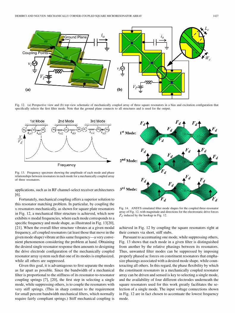
Fig. 12. (a) Perspective view and (b) top-view schematic of mechanically coupled array of three square resonators in a bias and excitation configuration thatspecifically selects the first filter mode. Note that the ground plane connects to all structures and is used for the output.
Fig. 13. Frequency spectrum showing the amplitude of each mode and phaserelationships between resonators in each mode for a mechanically coupled arrayof three resonators.
applications, such as in RF channel-select receiver architectures[6].
Fortunately, mechanical coupling offers a superior solution tothis resonator matching problem. In particular, by coupling the
resonators mechanically, as shown for square plate resonatorsin Fig. 12, a mechanical filter structure is achieved, which nowexhibits modal frequencies, where each mode corresponds to aspecific frequency and mode shape, as illustrated in Fig. 13[20],[21]. When the overall filter structure vibrates at a given modalfrequency, all coupled resonators (at least those that move in thegiven mode shape) vibrate at this same frequency—a very conve-nient phenomenon considering the problem at hand. Obtainingthe desired single resonator response then amounts to designingthe drive electrode configuration of the mechanically coupledresonator array system such that one of its modes is emphasized,while all others are suppressed.
Given this goal, it is advantageous to first separate the modesas far apart as possible. Since the bandwidth of a mechanicalfilter is proportional to the stiffness of its resonator-to-resonatorcoupling springs [7], [20], the first step in selecting a singlemode, while suppressing others, is to couple the resonators withvery stiff springs. (This in sharp contrast to the requirementfor small percent bandwidth mechanical filters, which normallyrequire fairly compliant springs.) Stiff mechanical coupling is
Fig. 14. ANSYS simulated filter mode shapes for the coupled three-resonatorarray of Fig. 12, with magnitude and directions for the electrostatic drive forcesF induced by the hookup in Fig. 12.
achieved in Fig. 12 by coupling the square resonators right attheir corners via short, stiff stubs.
Pursuant to accentuating one mode, while suppressing others,Fig. 13 shows that each mode in a given filter is distinguishedfrom another by the relative phasings between its resonators.Thus, unwanted filter modes can be suppressed by imposingproperly phased ac forces on constituent resonators that empha-size phasings associated with a desired mode shape, while coun-teracting all others. In this regard, the phase flexibility by whichthe constituent resonators in a mechanically coupled resonatorarray can be driven and sensed is key to selecting a single mode,and the availability of four different electrodes underneath thesquare resonators used for this work greatly facilitates the se-lection of a single mode. The input voltage connections shownin Fig. 12 are in fact chosen to accentuate the lowest frequencymode.

1428 JOURNAL OF MICROELECTROMECHANICAL SYSTEMS, VOL. 15, NO. 6, DECEMBER 2006
Fig. 15. Equivalent LCR circuit of a mechanically coupled three resonator array when operated (a) in the excitation configuration of Fig. 12 and (b) as a microme-chanical filter. The given circuit element values are used in the simulations in Fig. 16.
To illustrate the manner by which properly phased forcingsignals can accentuate the lowest mode, while suppressing allothers, Fig. 14 places the force distribution generated by theelectrode hookup of Fig. 12 over ANSYS simulations of theshapes of each of the three modes. Note how the force directions
imposed by the electrode connection of Fig. 12 all go in thesame direction as the mode shape displacements for the firstmode. Note also how this same force configuration opposes atleast one of the mode shape displacements for each of the othermodes, resulting in their suppression.
The resonance frequency of the first mode of the array inFig. 14 is given in terms of constituent resonator mass and stiff-nesses by
(36)
where and are the effective stiffness and mass, respec-tively, of the th resonator; is the effective mass of the thcoupling stub; and where the resonance frequency of the th con-stituent resonator is given by
(37)
If there is a slight change in the resonance frequency of anyof the constituent resonators of the array (i.e., a slight change in
or ), this will cause a much smaller shift in the array res-onance frequency, as it is averaged over resonators. However,the resonators will still be vibrating in unison at the same fre-quency, as they are mechanically coupled. The frequency shiftwill also cause slight distortion in the mode shapes, which mayresult in inadequate mode suppression and hence spurious re-sponses. However, as will be verified in Section VI, the amount
of this amplitude mismatch seems to be small enough that thespurious responses are not detectible—at least not by the mea-surement methods used here.
Although the array method should work for any strength ofmechanical coupling, it is advantageous to use stiff coupling fortwo main reasons.
1) To make sure that if the undesired modes cannot be suffi-ciently suppressed, any spurious outputs they cause willbe as far as possible from the chosen mode.
2) To prevent any resonance localization effects that maybe possible for a sufficiently large number of weaklycoupled structures [22].
Fig. 15(a) presents the equivalent LCR circuit representing themechanically coupled array structure of Fig. 12 with the designand electrical biases summarized in Table I. Here, each iden-tical resonator is modeled by an (identical) equivalent circuit ofthe form of Fig. 3, where the transformers modeling each port(i.e., each electrode) can be clearly seen. These circuits, how-ever, differ from Fig. 3 in that the transformers have all been nor-malized to have 1:1 turns ratios, for ease of circuit analysis. Toaffect this normalization, the lcr element values in Fig. 3 mustthemselves be transformed through the electromechanical cou-pling turns ratio to yield
(38)
which are more in line with the actual electrical impedance seenlooking into the device input and output terminals.
In Fig. 15, the corner couplers are modeled by LC equivalent-networks, the values of which are determined by fitting the
frequencies of the three modes obtained by simulating the LCRmodel to match the ANSYS simulated frequencies.

DEMIRCI AND NGUYEN: MECHANICALLY CORNER-COUPLED SQUARE MICRORESONATOR ARRAY 1429
TABLE IMECHANICALLY COUPLED SQUARE MICRORESONATOR ARRAY DESIGN
SUMMARY
Fig. 16. SPICE simulated spectra for the structure of Fig. 12 when operated asa mechanical filter [circuit of Fig. 15(b)] and a parallel resonator array [circuit ofFig. 15(a)], all compared with the response of a single resonator (dashed line).Note that the amplitude-axis of the zoomed plot corresponds to the amplitude-axis of the main plot.
Fig. 16 presents SPICE simulated spectra for the equivalentcircuit of the coupled structure for three cases
1) the structure operated as a parallel resonator array,using the hookup of Fig. 12, modeled by the circuit ofFig. 15(a);
2) the structure operated as an unterminated mechanicalfilter, with applied to one end resonator, and takenat the other end, all modeled by the circuit of Fig. 15(b);
3) a single stand-alone constituent resonator.In the simulated plot for the mechanical filter of case 2), three
distinct peaks are observed as expected, each of which corre-spond to the modes of Fig. 14. Unlike previous filters designedfor small, specific bandwidths [7], [20], the peaks for case 2)are a few MHz apart from each other, as governed by the use ofstiff mechanical couplers in this structure. The electrode-config-uration of the parallel array in case 1), on the other hand, effec-tively suppresses the second and third mode peaks, while raisingthe output current at the single desired lowest mode frequency(which is the first mode in Fig. 14), by more than 9 dB—all aspreviously advertised.
As illustrated in Fig. 16, the first mode of the coupled struc-ture does not exactly match the frequency of a stand-alone con-stituent resonator, although its frequency is very close. Should a
Fig. 17. Final cross section of a surface micromachined square plate microres-onator (cross section taken along AA in Fig. 1).
more exact match to the frequency of a stand-alone resonator berequired, note that the modes are quite predictable by the modelspresented and, thus, can be set to any needed frequency by design.
VI. EXPERIMENTAL RESULTS
Stand-alone, center-stem, and corner-supported microme-chanical square plate resonators and mechanically-coupledarrays of them with resonance frequencies between 60 and 72MHz were designed using the theory in Sections II, IV, andV and fabricated in a four-mask polysilicon surface micro-machining technology, similar to previously reported versions[7]. Fig. 17 presents the final cross-section of the fabricationprocess for a center-anchored square plate. The resonatorsconstituting the arrays were designed identical to stand-aloneresonators in all dimensions to allow an accurate comparison ofmotional resistances. Also, all the coupling stubs in the arraysof this paper are identical and have a length and width
of 1.4 .Table II summarizes the 68-MHz center-stem, and 72-MHz
corner-supported square plate designs of this paper. Figs. 18and 19 present SEMs of a fabricated 68-MHz single center-stemsquare resonator and mechanically-coupled array of three ofthem, respectively. Figs. 20 and 21 present the SEM’s of a fab-ricated 72-MHz stand alone corner-supported square resonatorand a mechanically-coupled array of seven of them.
For measurement and characterization, each resonatordie was mounted on a printed circuit board and placed in acustom-built vacuum chamber. DC and coaxial feedthroughsthrough a grounded metal block, which served as one of thevacuum chamber walls, provided electrical access to the circuitboard. A turbomolecular vacuum pump provided operatingpressures down to 200 , where viscous gas damping[24] is greatly suppressed, allowing resonators under test toexhibit their maximum ’s. Devices were measured using anHP 8751A network analyzer and S-parameter test set.
A. Stand-Alone Square Plate Resonators
Fig. 22 presents the frequency spectrum for a center-stemsquare plate resonator with 16 -sides measured undervacuum using the one-port test setup [26] shown in the figureinset and a dc-bias voltage of 25 V. As shown, this deviceexhibits a of 15,000 at 68.5 MHz, which is on par withfree-free beam resonator ’s [25] at the same frequency. Itsseries motional resistance extracted from the plot is 13.4
. It should be noted that although this device is perhaps bestoperated as a two-port, it is being operated as a one-port here for

1430 JOURNAL OF MICROELECTROMECHANICAL SYSTEMS, VOL. 15, NO. 6, DECEMBER 2006
TABLE IISQUARE PLATE RESONATOR DESIGN AND PERFORMANCE SUMMARY
Fig. 18. SEM of a 68-MHz center-stem square plate �mechanical resonator.
the purpose of comparing with the one-port resonator arrays tobe described later. As will be explained in more detail later, thearrays were hooked up in one-port configurations rather thantwo-port for electrical routing convenience. Whether devicesare hooked up as one- or two-ports has little impact on theoverall enhancement factor afforded by arraying.
Fig. 19. SEM of a 68-MHz mechanically coupled array of three center-stemsquare plate resonators.
Fig. 20. SEM of a 72-MHz corner-supported square plate �mechanical res-onator.
Fig. 21. SEM of a 72-MHz mechanically coupled array of seven corner-sup-ported square plate resonators.
Fig. 23 presents the measured frequency spectrum for thecorner-supported plate of Fig. 20, again under vacuum and using

DEMIRCI AND NGUYEN: MECHANICALLY CORNER-COUPLED SQUARE MICRORESONATOR ARRAY 1431
Fig. 22. Frequency response characteristic for a 68.5-MHz center-stem squareplate resonator.
a one-port test setup, but this time with a much higher dc-biasof 40 V, which was not possible with the center-stem devicedue to pull-in limitations, but which is now permissible by ahigher stiffness afforded by corner supports. The device has a
of 17,500, which is higher than the center-stem resonator, showing that removal of a (potentially misaligned) center
stem support does indeed improve the quality factor. The reso-nance frequency of the device is 71.7 MHz, which is greater thanthe frequency of the center-stem design, verifying the theoryof Section IV, where added support stiffness is responsible forfrequency increase. The measured of the corner-supporteddevice is 2.82 , which is much smaller than the 13.4 ex-hibited by the center-anchored device because a higher dc-biasvoltage is used (permitted by its higher pull-in voltage). Table IIpresents a comparison of theoretical and measured resonancefrequency and motional resistance values for center-anchor andcorner-supported devices.
To assess the validity of (33), Fig. 24 presents a compar-ison of frequency versus support length plots predicted by (34)and measured for a corner-supported square plate resonator,showing a clear increase in the resonance frequency with de-creasing support beam length. The slight deviation of the theoryfrom measurement for short support beams comes about be-cause (33) neglects the mass and stiffness of the small portionof the coupling beam at the plate corner. (See the definitionof in Fig. 7.) At the frequency of these devices, the beamlength corresponding to half of a quarter wavelength isaround 8 and the prediction by (34) loses its accuracy forbeams longer than this value due to its short beam assumption
, which explains the slight deviation between theoryand measurement for longer beams.
Fig. 25 presents a plot of measured quality factor versussupport beam length for a 68.5-MHz corner-supported squareplate resonator. The decreases rapidly below 20,000 forsupport beams shorter than 2.5 and it is almost constant
Fig. 23. Frequency response characteristic for a 71.7-MHz corner-supportsquare plate resonator.
Fig. 24. Comparison of frequency (f ) versus support length (L ) plots fora corner-support square resonator obtained by (34) and by measurement.
around 30,000 for beams longer than 4.5 . Although therewas no measured data for the case of quarter-wavelengthbeam length , the catastrophic pull-in voltagefor a square resonator with quarter wavelength supports iscalculated to be approximately 15 V, which is much lowerthan the 40 V pull-in voltage of the resonator with 4.5supports. Given that devices with 4.5 support beams cansustain much higher dc-bias voltages without pulling in andstill retain fairly high ’s around 30,000, they can potentiallyachieve much smaller . This encourages the use of 4.5support beam lengths in future designs to maximize bothand pull-down voltage. This measurement also shows thatcorner-supported square plates exhibit almost 2X larger ’scompared to center-anchored square plates, as well as free-freebeam micromechanical resonators [17], at the same frequency.
B. Mechanically-Coupled Resonator Arrays
Fig. 26 presents frequency characteristics measured usingtwo-port configurations under vacuum for a stand-alonecenter-stem device, and three-, five-, and eleven-resonator
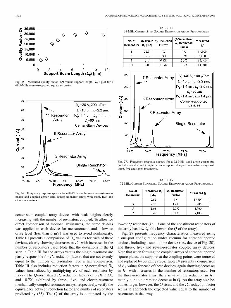
1432 JOURNAL OF MICROELECTROMECHANICAL SYSTEMS, VOL. 15, NO. 6, DECEMBER 2006
Fig. 25. Measured quality factor (Q) versus support length (L ) plot for a68.5-MHz corner-supported square resonator.
Fig. 26. Frequency response spectra for a 68-MHz stand-alone center-stem res-onator and coupled center-stem square resonator arrays with three, five, andeleven resonators.
center-stem coupled array devices with peak heights clearlyincreasing with the number of resonators coupled. To allow fordirect comparison of motional resistances, the same dc-biaswas applied to each device for measurement, and a low acdrive level (less than 5 mV) was used to avoid nonlinearity.Table III presents a comparison of values for each of thesedevices, clearly showing decreases in with increases in thenumber of resonators used. Note that the deviations in theseen in Table III for the arrays versus the single-resonator arepartly responsible for reduction factors that are not exactlyequal to the number of resonators. For a fair comparison,Table III also includes reduction factors in -normalizedvalues (normalized by multiplying of each resonator byits ). The -normalized reduction factors of 3.2X, 5.3X,and 10.7X, exhibited by three-, five- and eleven-resonatormechanically-coupled resonator arrays, respectively, verify theequivalence between reduction factor and number of resonatorspredicted by (35). The of the array is dominated by the
TABLE III68-MHZ CENTER-STEM SQUARE RESONATOR ARRAY PERFORMANCE
Fig. 27. Frequency response spectra for a 72-MHz stand-alone corner-sup-ported resonator and coupled corner-supported square resonator arrays withthree, five and seven resonators.
TABLE IV72-MHZ CORNER-SUPPORTED SQUARE RESONATOR ARRAY PERFORMANCE
lowest resonator (i.e., if one of the constituent resonators ofthe array has low , this lowers the of the array).
Fig. 27 presents frequency characteristics measured usinga one-port configuration under vacuum for corner-supporteddevices, including a stand-alone device (i.e., device of Fig. 20),and three-, five- and seven-resonator coupled array devices.Note that when forming the coupled arrays of corner-supportedsquare plates, the supports at the coupling points were removedand replaced by coupling stubs. Table IV presents a comparisonof values for each of these devices, again showing decreasesin with increases in the number of resonators used. Forthe three-resonator array, there is very little reduction in ,mainly due to a dramatic decrease in . As the array size be-comes larger, however, the rises, and the reduction factorseems to approach the expected value equal to the number ofresonators in the array.

DEMIRCI AND NGUYEN: MECHANICALLY CORNER-COUPLED SQUARE MICRORESONATOR ARRAY 1433
Fig. 28. Vibration mode shape of a seven-resonator array of square plates sup-ported by torsional beams at corners as simulated via ANSYS.
Part of the reason for the observed improvement in withincreasing array size is the reduction in the number of supportsper resonator, i.e., an increase in the number of resonators withonly two corner supports. In particular, the resonators at thetwo ends of the array have three supports, and thus, more pathsthrough which energy can be lost to the substrate (i.e., more an-chor dissipation) and higher stiffness compared to the inner res-onators with only two supports. Since the three resonator arrayhas two three-support resonators and only one two-port one,its performance is governed more by three-support resonators,which contributes to its lower overall . Larger arrays, on theother hand, are dominated by two-support resonators, giving riseto an improvement in the quality factor. By eliminating third an-chors at the two ends of the array, higher should be achievablein future designs.
In addition to higher , larger arrays of the corner-supportedtype also provide larger vibration amplitudes compared tosmaller arrays. In particular, since the mechanical stiffnessis smaller for the inner resonators, the vibration amplitudebecomes larger closer to the center of a large array, as seenin Fig. 28, which presents the ANSYS simulated vibrationmode-shape of a corner-supported seven-resonator array. Thisresults in further increases in the resonator array output, whichexplains why is still reduced 5.9X despite the degrada-tion by a factor of 0.5 (relative to a single resonator) in theseven-resonator array. The seven-resonator array of Fig. 21 hasa motional resistance of 480 , which is the lowest demon-strated to date for any capacitively actuated micromechanicalresonator at this frequency.
As expected from Section V, and as seen in Figs. 26 and27, in addition to lowering , mechanical coupling of res-onators also shifts the center frequency of the peak from thatof a stand-alone resonator. For the arrays of Fig. 26, the fre-quency shift is less than 0.02% and can be fixed by merely ad-justing the applied dc-bias voltage to constituent resonators.Note that the measured center frequency of the five-resonatorarray is larger than that of the 3-resonator array, and this does
Fig. 29. Measured frequency spectrum verifying suppression of the higher fre-quency filter modes by choice electrode excitation.
not agree with theory. In particular, theory predicts the oppo-site for the fundamental mode (used here) of any given array.In particular, theory expects the fundamental-mode frequencyto decrease as the number of resonators used in the array in-creases, since the ratio of fundamental-mode array stiffness toarray mass decreases as the number of resonators increases. Thiscomes about because in the fundamental mode, the resonatorsmove in such a way that their couplers do not flex [20], as clearlyillustrated in the first mode depiction in Fig. 13 for the case of athree-resonator array. When couplers do not flex, they add massto the system without adding stiffness, thereby decreasing thearray stiffness-to-mass ratio and in turn decreasing the overallarray frequency according to (33). The fact that the measuredcenter frequency of the five-resonator array of center-stem-sup-ported resonators is larger than that of the three-resonator arrayis likely caused by finite fabrication tolerances, which are sig-nificant here, since the peaks for the center-stem-supported res-onator arrays are so close together.
The corner-supported resonator arrays, on the other hand,show measured performance more in line with theoreticalprediciton, with frequency decreasing as the number of res-onators in the array increases. From Fig. 27, the frequency shiftsare seen to be significant enough that the mechanical designof the array should be adjusted if the array mode frequency isintended to match that of the original stand-alone resonator.
C. No Spurious Modes
To ascertain how effectively the unwanted modes in themechanically coupled array have been suppressed via strategicelectrode phasing, Fig. 29 presents the spectrum for a coupledarray of eleven center-stemmed square resonators measuredover a wide frequency range. The existence of only a singlepeak verifies that only the first filter mode is excited, while thehigher modes expected up to eleventh mode at 73.8 MHz (asdetermined by ANSYS), have been effectively suppressed.
D. Linearity
To assess the linearity of the array method, Fig. 30 presentsmeasured plots of output power vs. input power for thesingle corner-supported square plate microresonator of Fig. 20and array of five of them. In these plots, the curves wereobtained by driving the resonator or array in question by an

1434 JOURNAL OF MICROELECTROMECHANICAL SYSTEMS, VOL. 15, NO. 6, DECEMBER 2006
Fig. 30. Measured plots of output power P versus input power P for (a) thesingle corner-supported square plate microresonator of Fig. 20 and (b) an arrayof five of them, showing extrapolated IIP ’s of+14:8 dBm and+20:9 dBm,respectively.
input signal at its resonance frequency with a power levelindicated by the -axis. The curves, on the other hand,were obtained using the so-called “two-tone test” [10], whereout-of-band input signals at and , with
, were applied to the resonator or array input with equalpowers governed by the -axis, and the output signal taken at .(All consistent with the descriptions in Section III.) As shown,the single resonator exhibits an of 14 and an extrapolated
of , which is quite close to the theoretical pre-diction of using (20). The array of five mechani-cally coupled resonators exhibits a lower of 5 and a 9.7dB higher of , verifying significantly betterarray linearity, and again matching the theoreticalprediciton of (20). Thus, the described mechanically coupledresonator arraying technique does indeed reduce without de-grading device linearity, and in fact improves linearity, as pre-dicted by the theory of Section III.
E. Temperature Dependence
Fig. 31 presents a plot comparing frequency versus tempera-ture measurements for a 63-MHz stand alone center-anchoredsquare resonator and a coupled array of five of them. Theextracted ’s (temperature coefficients of frequency) of thestand-alone resonator and the coupled array areand , respectively, where the thermal stabilityof the resonator array is seen to be only slightly worse thanthe stand-alone resonator. This is somewhat reasonable, sincethe single square plate is smaller and anchored to the sub-strate only at a single point, while the array is both larger andanchored at several locations, making it more susceptible tostructure-to-substrate thermal expansion mismatches. Both
Fig. 31. Measured frequency versus temperature plots for a 63-MHz singlecenter-anchor square resonator and an array of five of them.
Fig. 32. Frequency characteristic for a 63-MHz five resonator coupled center-stem square resonator array measured under atmospheric pressure.
thermal dependences are on par or better than that measuredfor previous uncompensated free-free beam micromechanicalresonators [17], [25].
F. Operation Under Atmospheric Pressure
Up to this point, all of the measured curves shown in thispaper were done under 200 vacuum, with the intent ofeliminating viscous gas damping so as to better ascertain thedegree to which design-related loss mechanisms, such as an-chor or material losses, govern the of the more complex arraystructure. However, due their high stiffness, the square plate res-onators of this work operate with internal energies per cyclemuch higher than the energy losses per cycle caused by vis-cous gas damping. As such, the resonators and arrays of thiswork actually do not require vacuum to attain reasonably high
’s [27]. To illustrate, Fig. 32 presents the frequency character-istic for a five resonator array of 63-MHz center-anchor squareplate micromechanical resonators measured under atmosphericpressure, yet still showing a of 1,900, which is still sufficientfor use in many IF communication applications. This removal ofthe requirement for vacuum for stiff micron-scale (as opposed tonano-scale) micromechanical resonators has enormous implica-tions, as it allows a substantial reduction in the manufacturing
DEMIRCI AND NGUYEN: MECHANICALLY CORNER-COUPLED SQUARE MICRORESONATOR ARRAY 1435
cost of such devices, as well as increases their reliability andlifetime in commercial applications.
G. Conclusions
Mechanically coupled parallel resonator arrays with com-bined output currents have been demonstrated with seriesmotional resistances smaller than that of a single resonator byfactors equal to the number of resonators used in the array. Themethod demonstrated is also superior to mere combining ofresponses from separate resonators, since by mechanically cou-pling resonators, it automatically generates a single resonanceresponse (i.e., mode) from all resonators, without the need forabsolute matching of individual resonator responses. Althoughthis paper has focused mainly on lowering resonator imped-ances, another direct benefit of this approach is a substantialenhancement of the power handling capability of the combineddevice which is important for micromechanical resonatoroscillators and front-end filters, alike. As such, this techniquesolves many of the remaining issues that presently slow theinsertion of vibrating micromechanical resonator devices intopractical communication systems, and thus, helps clear a pathtowards the fully integrated communication systems targetedby vibrating RF MEMS technology.
ACKNOWLEDGMENT
The authors would like to thank the staff of Solid State Elec-tronics Laboratory (SSEL) at the University of Michigan, AnnArbor, for fabrication support.
REFERENCES
[1] J. Wang, J. E. Butler, T. Feygelson, and C. T.-C. Nguyen, “1.51-GHznanocrystalline diamond micromechanical disk resonator with mate-rial-mismatched isolating support,” in Tech. Digest, 17th Int. IEEEMEMS Conf., Maastricht, The Netherlands, Jan. 25–29, 2004, pp.641–644.
[2] C. T.-C. Nguyen, “Vibrating RF MEMS for next generation wirelessapplications,” in Proc. 2004 IEEE Custom Integrated Circuits Conf.,Orlando, FL, Oct. 3–6, 2004, pp. 257–264.
[3] H. A. C. Tilmans, W. D. Raedt, and E. Beyne, “MEMS for wirelesscommunications: ’From RF-MEMS components to RF-MEMS-SiP,”J. Micromech. Microeng., vol. 13, no. 4, pp. S139–S163, Jul. 2003.
[4] B. Bircumshaw, G. Lui, H. Takeuchi, T.-J. King, R. T. Howe, O.O’Reilly, and A. P. Pisano, “The radial bulk annular res.: Towards a50 ! MEMS filter,” in Dig. Tech. Papers, Transducers’03, Boston,MA, Jun. 8–12, 2003, pp. 875–878.
[5] S. Pourkamali and F. Ayazi, “SOI based HF and VHF single-crystalsilicon resonators with sub-100 nanometer vertical capacitive gaps,” inTech. Digest, 12th Int. Conf. Solid-State Sensors, Actuators, and Mi-crosystems (Transducers’03), Jun. 2–6, 2003, pp. 837–840.
[6] C. T.-C. Nguyen, “Transceiver front-end architectures using vibratingmicromechanical signal processors,” in Dig. Papers, Topical Mtg. Sil-icon Monolithic IC’s in RF Systems, Sep. 12–14, 2001, pp. 23–32.
[7] F. D. Bannon, III, J. R. Clark, and C. T.-C. Nguyen, “High-Q HF mi-croelectromechanical filters,” IEEE J. Solid-State Circuits, vol. 35, no.4, pp. 512–526, Apr. 2000.
[8] M. U. Demirci, M. A. Abdelmoneum, and C. T.-C. Nguyen, “Mechan-ically corner-coupled square microresonator array for reduced seriesmotional resistance,” in Tech. Digest, 12th Int. Conf. Solid-State Sen-sors, Actuators, and Microsystems (Transducers’03), Jun. 2–6, 2003,pp. 955–958.
[9] B. Razavi, RF Microelectronics. Upper Saddle River, NJ: Prentice-Hall, 1998.
[10] R. Navid, J. R. Clark, M. Demirci, and C. T.-C. Nguyen, “Third-orderintermodulation distortion in capacitively-driven CC-beam microme-chanical resonators,” in Tech. Digest, IEEE MEMS Conf., Interlaken,Switzerland, Jan. 21–25, 2001, pp. 228–231.
[11] S. Timoshenko, Vibration Problems in Engineering, 4 ed. New York:Wiley, 1974.
[12] H. A. C. Tilmans and R. Legtenberg, “Electrostatically driven vacuum-encapsulated polysilicon resonators: Part II. Theory and performance,”Sens. Actuators A, Phys., vol. A45, pp. 67–84, 1994.
[13] R. A. Johnson, Mechanical Filters in Electronics. New York: Wiley,1983.
[14] R. D. Blevins, Formulas for Natural Frequency and Mode Shape.Malabar, FL: Krieger, 1984.
[15] C. T.-C. Nguyen and R. T. Howe, “An integrated CMOS micromechan-ical resonator high-Q oscillator,” IEEE J. Solid-State Circuits, vol. 34,no. 4, pp. 440–455, Apr. 1999.
[16] Y.-W. Lin, S. Lee, Li S.-S, Y. Xie, Z. Ren, and C. T.-C. Nguyen, in Dig.Tech. Papers, 2004 IEEE Int. Solid-State Circuits Conf., 2003, vol. 47,pp. 322–323.
[17] K. Wang, A.-C. Wong, and C. T.-C. Nguyen, “VHF free-free beamhigh-Q micromechanical resonators,” J. Microelectromech. Syst, vol.8, no. 4, pp. 534–557, Dec. 1999.
[18] H. Nathanson, W. E. Newell, R. A. Wickstrom, and J. R. Davis, Jr, “Theresonant gate transistor,” IEEE Trans. Electron Devices, vol. ED-14,no. 1, pp. 117–133, Mar. 1967.
[19] S. Timoshenko, Strength of Materials, Part I: Elementary Theory andProblems, 3rd ed ed. Melbourne, FL: Krieger, 1958.
[20] K. Wang and C. T.-C. Nguyen, “High-order medium frequency mi-cromechanical electronic filters,” J. Microelectromech. Syst., vol. 8, no.4, pp. 534–557, Dec. 1999.
[21] D. S. Greywall and P. S. Busch, “Coupled micromechanical drumheadresonators with practical application as electromechanical bandpassfilters,” J. Micromech. Microeng., vol. 12, no. 6, pp. 925–938,Nov. 2002.
[22] M. P. Castanier and C. Pierre, “Individual and interactive mechanismsfor localization and dissipation in a mono-coupled nearly-periodicstructure,” J. Sound Vibrat., vol. 168, no. 3, pp. 479–505, Dec. 1993.
[23] H. Guckel, D. W. Burns, H. A. C. Tilmans, D. W. DeRoo, and C.Rutiglano, “The mechanical properties of fine-grained polysilicon: Therepeatability issue,” in Proc. IEEE Solid-State Sens. Actuator WorkshopTech. Dig, Hilton Head, SC, Jun. 1998, pp. 96–99.
[24] W. E. Newell, “Miniaturization of tuning forks,” Science, vol. 161, pp.1320–1326, Sep. 1968.
[25] M. U. Demirci and C. T.-C. Nguyen, “Higher-Mode free-free beam mi-cromechanical resonators,” in Proc. Annu. IEEE Int. Frequency ControlSymp., Tampa, FL, May 5–8, 2003, pp. 810–818.
[26] J. R. Clark, W.-T. Hsu, and C. T.-C. Nguyen, “Measurement tech-niques for capacitively-transduced VHF-to-UHF micromechanical res-onators,” in Dig. Technical Papers, 11th Int. Conf. Solid-State SensorsActuators, pp. 1118–1121.
[27] J. Wang, Z. Ren, and C. T.-C. Nguyen, “Self-aligned 1.14-GHz vi-brating radial-mode disk resonators,” in Tech. Digest, 12th Int. Conf.Solid-State Sensors, Actuators, and Microsystems (Transducers’03),Jun. 2–6, 2003, pp. 947–950.
Mustafa U. Demirci (S’98–M’06) received the B.S.degree in electrical and electronics engineering fromMiddle East Technical University, Ankara, Turkey, in1997, and the M.S. and Ph.D. degrees in electricalengineering from the University of Michigan, AnnArbor, in 1999 and 2005, respectively. His Ph.D. re-search involved integrated circuit technology and mi-croelectromechanical systems for communications.
In 2005, he joined Toyota Technical Center, AnnArbor, MI, where he is currently a Senior ResearchScientist.
Dr. Demirci was a recipient of the Turkish Scientific and Technical ResearchCouncil (TUBITAK) NATO-A1 scholarship in 1997.
Clark T.-C. Nguyen (S’90–M’95–SM’01) receivedthe B. S., M. S., and Ph.D. degrees from the Univer-sity of California, Berkeley, in 1989, 1991, and 1994,respectively, all in electrical engineering and com-puter sciences.
In 1995, he joined the faculty of the University ofMichigan, Ann Arbor, where he was a Professor inthe Department of Electrical Engineering and Com-puter Science until mid-2006. In 2006, he joined theDepartment of Electrical Engineering and ComputerSciences at the University of California, Berkeley,

1436 JOURNAL OF MICROELECTROMECHANICAL SYSTEMS, VOL. 15, NO. 6, DECEMBER 2006
where he is currently a Professor and a Director of the Berkeley Sensor andActuator Center. His research interests focus upon microelectromechanicalsystems (MEMS) and include integrated micromechanical signal processorsand sensors, merged circuit/micromechanical technologies, RF communicationarchitectures, and integrated circuit design and technology. From 1995 to1997, he was a member of the National Aeronautics and Space Administra-tion (NASA)’s New Millennium Integrated Product Development Team onCommunications, which roadmapped future communications technologies forNASA use into the turn of the century. In 2001, he founded Discera, Inc.,a company aimed at commercializing communication products based uponMEMS technology, with an initial focus on the very vibrating micromechanicalresonators pioneered by his research in past years. He served as Vice Presidentand Chief Technology Officer (CTO) of Discera until mid-2002, at which pointhe joined the Defense Advanced Research Projects Agency (DARPA) on anIPA, where he served for 3 1/2 years as the Program Manager of the MEMS,Micro Power Generation (MPG), Chip-Scale Atomic Clock (CSAC), MEMSExchange (MX), Harsh Environment Robust Micromechanical Technology(HERMIT), Micro Gas Analyzers (MGA), Radio Isotope Micropower Sources(RIMS), RF MEMS Improvement (RFMIP), Navigation-Grade Integrated
Micro Gyroscopes (NGIMG), and Micro Cryogenic Coolers (MCC) programs,in the Microsystems Technology Office of DARPA.
Prof. Nguyen received the 1938E Award for Research and Teaching Excel-lence from the University of Michigan in 1998, an EECS Departmental Achieve-ment Award in 1999, the Ruth and Joel Spira Award for Teaching Excellence in2000, and the University of Michigan’s 2001 Henry Russel Award. He recentlyreceived the Cady Award from the 2006 IEEE Frequency Control Symposium.Among his publication accolades are the Jack Raper Award from 2005 IEEEInternational Solid-State Circuits Conference, the 2004 DARPA Best TechnicalPresentation Award, the Best Invited Paper Award at the 2004 IEEE Custom In-tegrated Circuits Conference, and together with his students, the Best StudentPaper Award in Category 1 at the 2005 Joint IEEE Frequency Control/PreciseTime and Timing Interval (PTTI) Symposium, the Best Student Paper Award inthe Frequency Control Category at the 2004 IEEE Ultrasonics, Ferroelectrics,and Frequency Control Symposium, and the Roger A. Haken Best Student PaperAwards at the 1998 and 2003 IEEE International Electron Devices Meetings. Todate, he has organized and chaired a total of 35 IEEE and DARPA workshops.
![Project: IEEEP802 ... · PDF file[ ] T.Norimatsu,et.al.,”AUWB-IRTransmitterwithDigitallyControlledPulseGenerator”,IEEEJournal ofSolidCircuits,Vol](https://img.pdfslide.net/doc/110x75/5a9238487f8b9a30358b7a16/project-ieeep802-tnorimatsuetalauwb-irtransmitterwithdigitallycontrolledpulsegeneratorieeejournal.jpg)


![Liquid Encapsulation Technology for Microelectromechanical ... · Liquid Encapsulation Technology for Microelectromechanical Systems Norihisa Miki ... [27]. Therefore, sealing with](https://img.pdfslide.net/doc/110x75/5ebd6745ad290220a7044b42/liquid-encapsulation-technology-for-microelectromechanical-liquid-encapsulation.jpg)