Embed Size (px)
Citation preview
2
SY
ST
EM
DA
TA
AN
D T
RO
UB
LE
SH
OO
TIN
G
19JOYSTICKS
AND
GAME PORTS
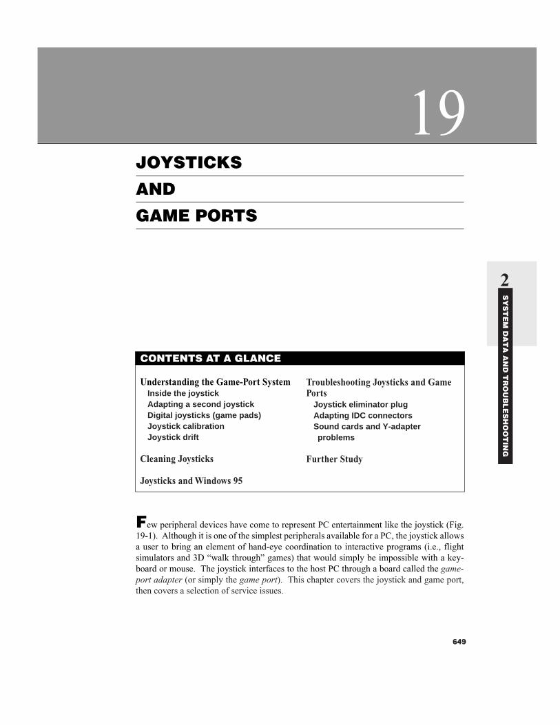
Few peripheral devices have come to represent PC entertainment like the joystick (Fig.19-1). Although it is one of the simplest peripherals available for a PC, the joystick allowsa user to bring an element of hand-eye coordination to interactive programs (i.e., flightsimulators and 3D “walk through” games) that would simply be impossible with a key-board or mouse. The joystick interfaces to the host PC through a board called the game-port adapter (or simply the game port). This chapter covers the joystick and game port,then covers a selection of service issues.
649
CONTENTS AT A GLANCE
Understanding the Game-Port SystemInside the joystickAdapting a second joystickDigital joysticks (game pads)Joystick calibrationJoystick drift
Cleaning Joysticks
Joysticks and Windows 95
Troubleshooting Joysticks and GamePorts
Joystick eliminator plugAdapting IDC connectorsSound cards and Y-adapter problems
Further Study
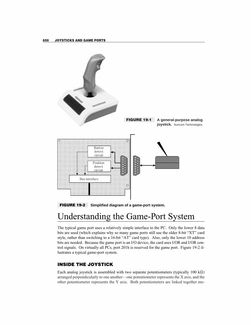
Understanding the Game-Port SystemThe typical game port uses a relatively simple interface to the PC. Only the lower 8 databits are used (which explains why so many game ports still use the older 8-bit “XT” cardstyle, rather than switching to a 16-bit “AT” card type). Also, only the lower 10 addressbits are needed. Because the game port is an I/O device, the card uses I/OR and I/OR con-trol signals. On virtually all PCs, port 201h is reserved for the game port. Figure 19-2 il-lustrates a typical game-port system.
INSIDE THE JOYSTICK
Each analog joystick is assembled with two separate potentiometers (typically 100 kΩ)arranged perpendicularly to one another—one potentiometer represents the X axis, and theother potentiometer represents the Y axis. Both potentiometers are linked together me-
650 JOYSTICKS AND GAME PORTS
FIGURE 19-1 A general-purpose analogjoystick. Suncom Technologies
Buttondetectcircuit
Positiondetectcircuit
Bus interface
FIGURE 19-2 Simplified diagram of a game-port system.
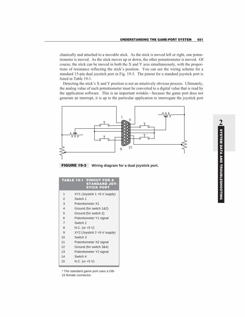
chanically and attached to a movable stick. As the stick is moved left or right, one poten-tiometer is moved. As the stick moves up or down, the other potentiometer is moved. Ofcourse, the stick can be moved in both the X and Y axis simultaneously, with the propor-tions of resistance reflecting the stick’s position. You can see the wiring scheme for astandard 15-pin dual joystick port in Fig. 19-3. The pinout for a standard joystick port islisted in Table 19-1.
Detecting the stick’s X and Y position is not an intuitively obvious process. Ultimately,the analog value of each potentiometer must be converted to a digital value that is read bythe application software. This is an important wrinkle—because the game port does notgenerate an interrupt, it is up to the particular application to interrogate the joystick port
UNDERSTANDING THE GAME-PORT SYSTEM 651
2
SY
ST
EM
DA
TA
AN
D T
RO
UB
LE
SH
OO
TIN
G
91
158
FIGURE 19-3 Wiring diagram for a dual joystick port.
TABLE 19-1 PINOUT FOR ASTANDARD JOY-STICK PORT
1 XY1 (Joystick 1 +5-V supply)
2 Switch 1
3 Potentiometer X1
4 Ground (for switch 1&2)
5 Ground (for switch 2)
6 Potentiometer Y1 signal
7 Switch 2
8 N.C. (or +5 V)
9 XY2 (Joystick 2 +5-V supply)
10 Switch 3
11 Potentiometer X2 signal
12 Ground (for switch 3&4)
13 Potentiometer Y2 signal
14 Switch 4
15 N.C. (or +5 V)
* The standard game port uses a DB-15 female connector.

regularly. You might imagine that such a conversion would use an Analog-to-DigitalConverter (ADC). However, an ADC provides much greater resolution than is needed andits conversions require a relatively long time. Current game-port conversion circuits use amultivibrator element.
Ultimately, the resistance of each potentiometer is determined indirectly by measuringamount of time required for a charged capacitor to discharge through the particular poten-tiometer. If a certain axis is at 0 Ω, the multivibrator’s internal capacitor will discharge inabout 24.2 µs, and at 100 kΩ, the multivibrator’s capacitor will discharge in about 1124µs. Because this is a relatively linear relationship, the discharge time can easily be equatedto potentiometer position (an actual routine to accomplish this requires only about 16 linesof assembler code). The multivibrator technique also simplifies the circuitry needed onthe game-port adapter—it is really the application that is doing the work.
A joystick also has one or two buttons. As you see from Fig. 19-3, the buttons are typi-cally open, and their closed state can be detected by reading the byte at 201h. Because thegame port is capable of supporting two joysticks simultaneously (each with two buttons),the upper four bits of 201h indicate the on/off status of all four buttons.
ADAPTING A SECOND JOYSTICK
Although the typical game port is capable of supporting two joysticks, most joystick prod-ucts only connect a single joystick. This means that only “half” the game port is being uti-lized. You can purchase a joystick Y-adapter from any computer store or construct aY-adapter using the pinout in Table 19-2. You’ll need a DB-15 male connector to attachto the game port and two DB-15 female connectors to attach to each of the two joysticks.
652 JOYSTICKS AND GAME PORTS
TABLE 19-2 PINOUT FOR A JOYSTICK “Y” ADAPTER
GAME PORT JOYSTICK 1 JOYSTICK 2DB-15 MALE DB-15 FEMALE DB-15 FEMALE
1 XY1 (joystick 1 +5-V supply) 1
2 Switch 1 2
3 Potentiometer X1 signal 3
4 Ground (for switch 1&2) 4
5 Ground (for switch 2) 5
6 Potentiometer Y1 signal 6
7 Switch 2 7
8 N.C. (or +5 V) 8
9 XY2 (Joystick 2 +5-V supply) 1
10 Switch 3 2
11 Potentiometer X2 signal 3
12 Ground (for switch 3&4) 4 and 5
13 Potentiometer Y2 signal 6
14 Switch 4 7
15 N.C. (or +5 V) 8
DIGITAL JOYSTICKS (GAME PADS)
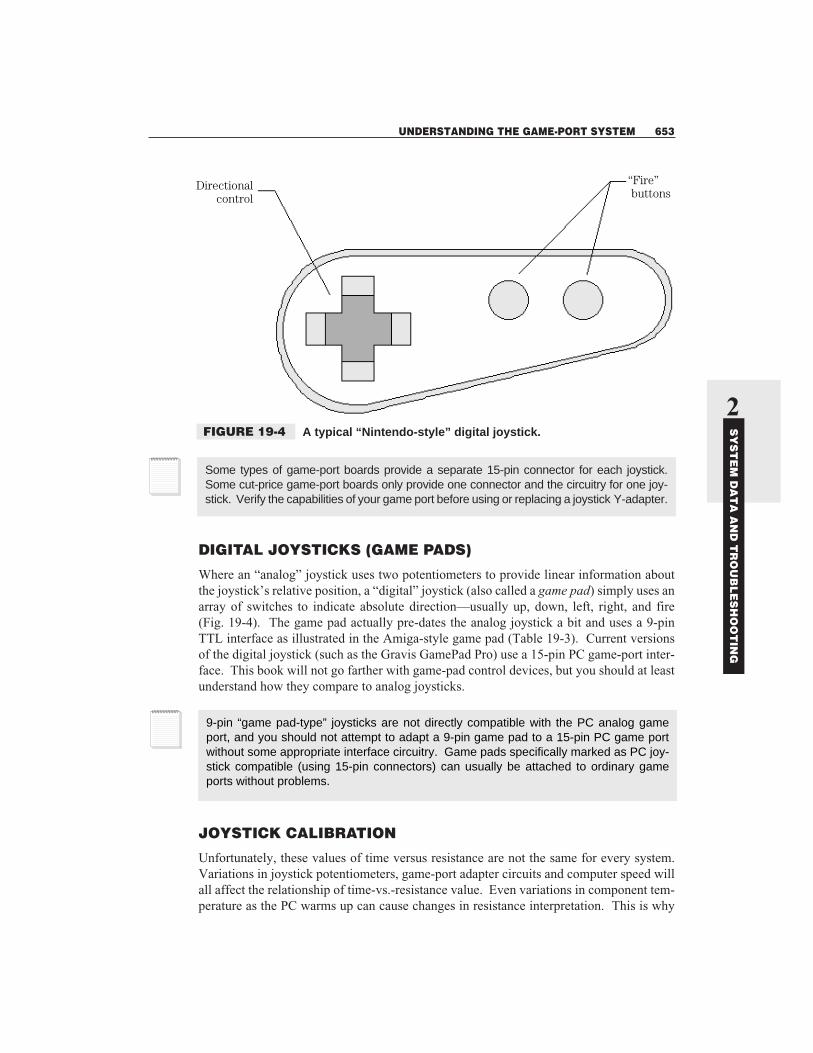
Where an “analog” joystick uses two potentiometers to provide linear information aboutthe joystick’s relative position, a “digital” joystick (also called a game pad) simply uses anarray of switches to indicate absolute direction—usually up, down, left, right, and fire(Fig. 19-4). The game pad actually pre-dates the analog joystick a bit and uses a 9-pinTTL interface as illustrated in the Amiga-style game pad (Table 19-3). Current versionsof the digital joystick (such as the Gravis GamePad Pro) use a 15-pin PC game-port inter-face. This book will not go farther with game-pad control devices, but you should at leastunderstand how they compare to analog joysticks.
JOYSTICK CALIBRATION
Unfortunately, these values of time versus resistance are not the same for every system.Variations in joystick potentiometers, game-port adapter circuits and computer speed willall affect the relationship of time-vs.-resistance value. Even variations in component tem-perature as the PC warms up can cause changes in resistance interpretation. This is why
UNDERSTANDING THE GAME-PORT SYSTEM 653
2
SY
ST
EM
DA
TA
AN
D T
RO
UB
LE
SH
OO
TIN
G
Some types of game-port boards provide a separate 15-pin connector for each joystick.Some cut-price game-port boards only provide one connector and the circuitry for one joy-stick. Verify the capabilities of your game port before using or replacing a joystick Y-adapter.
9-pin “game pad-type” joysticks are not directly compatible with the PC analog gameport, and you should not attempt to adapt a 9-pin game pad to a 15-pin PC game portwithout some appropriate interface circuitry. Game pads specifically marked as PC joy-stick compatible (using 15-pin connectors) can usually be attached to ordinary gameports without problems.
“Fire” buttons
Directionalcontrol
FIGURE 19-4 A typical “Nintendo-style” digital joystick.

each application program that uses a joystick comes with a calibration routine. Calibrationallows the application to measure values for center and corner positions. With this data asa base, the application can extrapolate all other joystick positions.
JOYSTICK DRIFT
The term drift (rolling) is used to indicate a loss of control by the joystick. There are sev-eral possible reasons for this. As a technician, you should understand the reasons why driftoccurs, and how to correct such problems. First, drift might be the result of a system con-flict. Because the game port does not generate an interrupt, conflicts rarely result in sys-tem crashes or lockups, but another device feeding data to port 201h can easily upsetjoystick operation. If you have sound boards or multi-port I/O boards in your systemequipped with game ports, be sure to disable any unused ports (check with the user in-structions for individual boards to disable extra game ports).
Another possible cause of drift is heat. Once PCs are started up, it is natural for thepower used by most components to be dissipated as heat. Unfortunately, heating tends tochange the value of components. For logic circuits, this is typically not a problem, but foranalog circuits, the consequences can be much more pronounced. As heat changes the val-ues of a multivibrator circuit, timing (and thus positional values) will shift. As the circuitwarms up, an error creeps into the joystick. Well-designed game-port adapters will usehigh-quality, low-drift components that minimize the affects of heat-related drift. It is in-teresting that the joystick itself is rarely the cause of drift. If you can compensate for driftby periodically re-calibrating the joystick, try a better-quality game-port adapter board.
Finally, the quality of calibration is only as good as the calibration routine itself. A pooror inaccurate routine will tend to calibrate the joystick incorrectly. Try another applica-tion. If another application can calibrate and use the joystick properly, you should suspecta bug in the particular application. Try contacting the application manufacturer to find ifthere is a patch or fix available.
654 JOYSTICKS AND GAME PORTS
TABLE 19-3PINOUT FOR ANAMIGA-TYPEGAME PAD
PIN GAME PAD
1 Forward
2 Back
3 Left
4 Right
5 n/c
6 Button (fire) 1
7 +5 V
8 Ground
9 Button (fire) 2
* Game pads often use aDB-9 female connector.
Cleaning JoysticksOrdinarily, the typical joystick should not require routine cleaning or maintenance. Mostjoysticks use reasonably reliable potentiometers that should last for the life of the joystick.The two major enemies of a joystick are wear and dust. Wear occurs during normal use aspotentiometer sliders move across the resistive surface—it can’t be avoided. Over time,wear will effect the contact resistance values of both potentiometers. Uneven wear will re-sult in uneven performance. When this becomes noticeable, it is time to buy a new joystick.
Dust presents another problem. The open aperture at the top of a joystick is an invita-tion for dust and other debris. Because dust is conductive, it can adversely affect poten-tiometer values and interfere with slider contacts. If the joystick seems to produce a jumpyor non-linear response to the application, it might be worth trying to clean the joystick,rather than scrapping it. Turn off the computer and disconnect the joystick. Open the joy-stick that is usually held together by two screws in the bottom housing. Remove the bot-tom housing and locate the two potentiometers. Most potentiometers have small openingssomewhere around their circumference. Dust out the joystick area with compressed airand spray a small quantity of good-quality electrical contact cleaner into each potentiome-ter. Move the potentiometer through its complete range of motion a few times and allowseveral minutes for the cleaner to dry. Re-assemble the housing and try the joystick again.If problems persist, replace the joystick.
Joysticks and Windows 95Games have traditionally been a domain of DOS, so there has been little support for joy-sticks under Windows. However, now that games are routinely using Windows 95 (takingadvantage of such features DirectX and Direct3D), you can now install and calibrate a va-riety of joysticks under Windows 95. Open your Control panel and look for the Joystickicon. If the Joystick icon appears in your Control panel, joystick support is already in-stalled and you can skip to the Game controller setup. If you have not yet added your PCgame port as New hardware in the Windows 95 Control panel, you should do this first:
1 Click the Start button.2 Select Settings, then Control panel.3 In the Control panel, look for a Joystick icon. If it’s there, skip to the Game controller
setup. If not, doubleclick the Add new hardware icon to start the Add new hardwarewizard.
4 When prompted to have Windows search for new hardware, select No. Click Next tocontinue.
5 Select Sound, video and game controllers, then click Next.6 Select the Manufacturer and game port joystick (or other appropriate model). This will
add the game port as a device. Click Next.7 If resource settings are given as 0201-0201, click Next. Windows will look for the re-
quired files. If it can’t find these files, it will ask you to insert your Windows 95 CD ordisk.
JOYSTICKS AND WINDOWS 95 655
2
SY
ST
EM
DA
TA
AN
D T
RO
UB
LE
SH
OO
TIN
G

8 When the files have been installed, click Finished.9 Shut down your computer and restart Windows 95 to enable your game-port support.
Once your game-port driver has been added, a joystick icon appears in your Controlpanel. Use this to set up and calibrate your joystick:
1 Doubleclick the Joystick icon in the Control panel.2 In the Joystick configuration section, choose the appropriate joystick type from the list.3 After selecting your joystick configuration, click the Calibration button and carefully
follow the onscreen instructions.
You should not be able to use the joystick under any Windows 95 game or other joy-stick-aware application.
Troubleshooting Joysticks and Game PortsThe unique advantage to troubleshooting this area of a PC is that there is surprisingly lit-tle to actually go wrong. In virtually all cases, problems reside in either the joystick, thegame-port adapter, or the application software. This part of the chapter provides you withsome handy troubleshooting issues and examines a suite of perplexing joystick problems.
JOYSTICK ELIMINATOR PLUG
From time to time, you might find yourself testing a game port, but have no joystick handy(or it might be too much of a hassle to “borrow” a joystick already connected to a workingPC). You can construct a very simple circuit with two resistors (Fig. 19-5) that can “fool”the game port into thinking that a real joystick is attached. This “joystick eliminator” plugsimply places the cursor in a far corner of the display.
656 JOYSTICKS AND GAME PORTS
x
1
9
158
15 V
y
Both resistors 5 100 kV
FIGURE 19-5 A simple “joystickeliminator” plug forgame-port testing.
You can use the CALJOY22.ZIP and JOY2.EXE programs on the companion CD to aidyou with testing and calibrating joysticks.
ADAPTING IDC CONNECTORS
Some multi-I/O boards implement the game port as a 16-pin IDC (ribbon cable) connec-tor—assuming that you’ll use a DB-15 connector “plate” in another open card slot andsimply connect the DB-15 “plate” to the multi-I/O card using a 16-pin ribbon cable. Thepin assignments are all identical (pin 16 of the IDC connector is just left unused), but re-member that the pin order is different between IDC and DB-style connectors. For exam-ple, the top row of a DB-15 connector runs pins 9 through 15, but the top row of an IDCcable uses pins 2, 4, 5, 6, 10, 12, 14, and 16.
SOUND CARDS AND Y-ADAPTER PROBLEMS
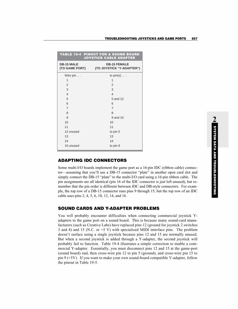
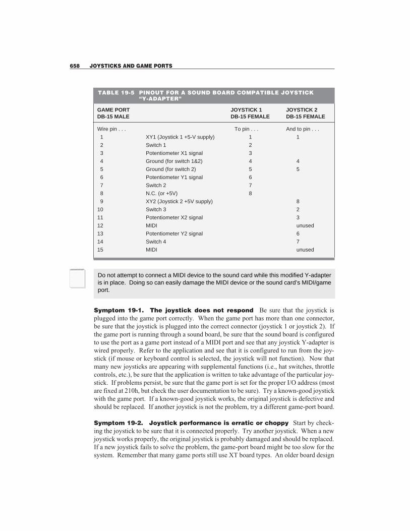
You will probably encounter difficulties when connecting commercial joystick Y-adapters to the game port on a sound board. This is because many sound-card manu-facturers (such as Creative Labs) have replaced pins 12 (ground for joystick 2 switches3 and 4) and 15 (N.C. or +5 V) with specialized MIDI interface pins. The problemdoesn’t surface using a single joystick because pins 12 and 15 are normally unused.But when a second joystick is added through a Y-adapter, the second joystick willprobably fail to function. Table 19-4 illustrates a simple correction to enable a com-mercial Y-adapter. Essentially, you must disconnect pins 12 and 15 at the game-port(sound board) end, then cross-wire pin 12 to pin 5 (ground), and cross-wire pin 15 topin 9 (+5V). If you want to make your own sound-board compatible Y-adapter, followthe pinout in Table 19-5.
TROUBLESHOOTING JOYSTICKS AND GAME PORTS 657
2
SY
ST
EM
DA
TA
AN
D T
RO
UB
LE
SH
OO
TIN
G
TABLE 19-4 PINOUT FOR A SOUND BOARDJOYSTICK CABLE ADAPTER
DB-15 MALE DB-15 FEMALE(TO GAME PORT) (TO JOYSTICK “Y-ADAPTER”)
Wire pin . . . to pin(s) . . .
1 1
2 2
3 3
4 4
5 5 and 12
6 6
7 7
8 8
9 9 and 15
10 10
11 11
12 unused to pin 5
13 13
14 14
15 unused to pin 9
Symptom 19-1. The joystick does not respond Be sure that the joystick isplugged into the game port correctly. When the game port has more than one connector,be sure that the joystick is plugged into the correct connector (joystick 1 or joystick 2). Ifthe game port is running through a sound board, be sure that the sound board is configuredto use the port as a game port instead of a MIDI port and see that any joystick Y-adapter iswired properly. Refer to the application and see that it is configured to run from the joy-stick (if mouse or keyboard control is selected, the joystick will not function). Now thatmany new joysticks are appearing with supplemental functions (i.e., hat switches, throttlecontrols, etc.), be sure that the application is written to take advantage of the particular joy-stick. If problems persist, be sure that the game port is set for the proper I/O address (mostare fixed at 210h, but check the user documentation to be sure). Try a known-good joystickwith the game port. If a known-good joystick works, the original joystick is defective andshould be replaced. If another joystick is not the problem, try a different game-port board.
Symptom 19-2. Joystick performance is erratic or choppy Start by check-ing the joystick to be sure that it is connected properly. Try another joystick. When a newjoystick works properly, the original joystick is probably damaged and should be replaced.If a new joystick fails to solve the problem, the game-port board might be too slow for thesystem. Remember that many game ports still use XT board types. An older board design
658 JOYSTICKS AND GAME PORTS
TABLE 19-5 PINOUT FOR A SOUND BOARD COMPATIBLE JOYSTICK “Y-ADAPTER”
GAME PORT JOYSTICK 1 JOYSTICK 2DB-15 MALE DB-15 FEMALE DB-15 FEMALE
Wire pin . . . To pin . . . And to pin . . .
1 XY1 (Joystick 1 +5-V supply) 1 1
2 Switch 1 2
3 Potentiometer X1 signal 3
4 Ground (for switch 1&2) 4 4
5 Ground (for switch 2) 5 5
6 Potentiometer Y1 signal 6
7 Switch 2 7
8 N.C. (or +5V) 8
9 XY2 (Joystick 2 +5V supply) 8
10 Switch 3 2
11 Potentiometer X2 signal 3
12 MIDI unused
13 Potentiometer Y2 signal 6
14 Switch 4 7
15 MIDI unused
Do not attempt to connect a MIDI device to the sound card while this modified Y-adapteris in place. Doing so can easily damage the MIDI device or the sound card’s MIDI/gameport.

might not be able to process joystick signals fast enough to provide adequate signaling tothe system. Not only should you try another game-port adapter, but you should use aspeed-adjusting game port.
Symptom 19-3. The joystick is sending incorrect information to the sys-tem—the joystick appears to be drifting First, check the application to be surethat the joystick is calibrated correctly. If you cannot calibrate the joystick, the applicationmight not support the joystick properly—try another application. Be sure that there are noother active devices in the system (such as other game ports) using I/O port 201h. If thishappens, data produced on those other boards will adversely affect the game port that youare using. If all unused game ports are disabled, check the active game port. Poor-qualitygame ports can drift. Try a newer, low-drift or speed-adjusting game-port board.
Symptom 19-4. The basic X/Y, two-button features of the joystick work,but the hat switch, throttle controls, and supplemental buttons do notseem to respond In virtually all cases, the joystick is configured wrong. Check theapplication first—many new applications provide several different joystick options,and even allow you to define the particular use of each feature from within the appli-cation itself.
Check the joystick definition files next. Your joystick probably requires a supple-mental definition file (i.e., an .FCS file) to use all of the joystick’s particular features.Finally, check the game-port type. You might need a “dual-port” game-port adapter,rather than an inexpensive “single-port” game-port adapter. Some enhanced joysticksuse both joystick positions (i.e., the XY axis and fire buttons make up one joystick, andthe throttle and other buttons take up the other position). You might need to install adual-port game-port card.
Symptom 19-5. A “Joystick not connected” error appears under Win-dows 95 Windows 95 does not recognize the game-port hardware. Check the game-port driver first. Use the Device manager under Windows 95 to examine the resourcesassigned to the game-port driver. Typically, the resource range should be set to 201hthrough 201h (only one address location). If the game-port entry has a yellow icon nextto it, there is a hardware conflict in the system, and other hardware is also trying to usethe same I/O location.
Next, check the game-port hardware for proper configuration. The game-port cardshould be installed properly into its bus slot. Be sure that the game port is enabled (this istypical of game ports integrated onto sound cards or multi-I/O cards). If a sound card en-ables you to switch a 15-pin port between MIDI and joystick, see that the jumper is set tothe “joystick” position. Be sure that the joystick cable is not cut or damaged anywhere,and see that it is attached securely to the game port. Finally, test a known-good joystickon the system. If a new joystick works as expected, the original joystick is probably suf-fering from internal wiring damage.
Symptom 19-6. The joystick drifts frequently and requires recalibrationThis type of symptom is usually the result of problems with the game-port adapter. Try adifferent game-port adapter and see if the problem persists. If problems disappear, you
TROUBLESHOOTING JOYSTICKS AND GAME PORTS 659
2
SY
ST
EM
DA
TA
AN
D T
RO
UB
LE
SH
OO
TIN
G

simply need a better-quality or speed-adjusting game port. Otherwise, test a known-goodjoystick on the system. If a new joystick works as expected, the original joystick is prob-ably suffering from internal wiring damage and should be replaced.
Symptom 19-7. The joystick handle has lost tension—it no longer“snaps” back to the center This problem might be accompanied by a rattling soundwithin the joystick. In most cases, a spring has popped out of place inside the joystick.Check the joystick for internal damage. Open the joystick and see if any springs or clipshave slipped out of place. Replace any springs or clips (if possible). Some joysticks alsouse mechanical latches that can enable or disable the “spring action” of the X and Y axis.Check to see that any such latches are enabled. If you cannot locate or correct the prob-lem, simply replace the joystick outright.
Symptom 19-8. The joystick responds, but refuses to accept a calibra-tion In virtually all cases, the problem is with your game-port adapter. Check the hard-ware setup—be sure that there are no other devices in the system using the I/O addressassigned to your game port (i.e., 201h). If more than one adapter in your system hasgame-port capability, see that only one game port is enabled. Replace the game port, orenable a different game port in the system. If drift issues continue with different appli-cations, you might need to replace the game-port adapter with a “low drift” or speed-ad-justing model.
Symptom 19-9. The hat switch and buttons on a joystick work only in-termittently (if at all) This problem also applies to stand-alone pedals. In most cases,erratic behavior of a joystick’s “enhanced features” is a symptom of game-port speedproblems. Check the joystick first. Try a known-good joystick. If the problems disap-pear, the original joystick might in fact be defective. If the problems persist, you have agame-port problem. Be sure that there are no other devices in the system using the I/O ad-dress assigned to your game port (i.e., 201h). If more than one adapter in your system hasgame-port capability, see that only one game port is enabled. If drift issues continue withdifferent applications, you might need to replace the game-port adapter with a “low drift”or speed-adjusting model.
Symptom 19-10. When downloading FCS (or calibration) files to a joy-stick, the line saying: “Put switch into calibrate” doesn’t change whenthe download switch is moved” This is a typical problem with advanced joysticks.In most cases, the joystick needs to be “cleared.” Clear the joystick—rock the downloadswitch back to “analog,” then to “calibrate”—this should clear the joystick for a new cali-bration download. Try downloading the FCS file again. If problems persist, the actualswitch might be defective. Try a known-good joystick instead.
Symptom 19-11. To download a calibration file, you need to rock the redswitch back and forth a number of times (or hit the <Enter> key a numberof times) to get it to 100% This is virtually always the result of a keyboard-con-troller (keyboard BIOS) compatibility problem. Upgrade the keyboard controller (key-board BIOS). Some advanced joystick products do not interact well with the host
660 JOYSTICKS AND GAME PORTS

computer’s keyboard controller. For example, Thrustmaster’s Mark II experiences knownmicrocode problems with a few of keyboard controller chips on the market. These includeAMI versions (D, B, 8, 0), Acer, and Phoenix. You might need to replace the keyboardcontroller with a later version.
Symptom 19-12. A joystick cannot be used with a PC using a sound cardwith an ESS or OPTi chipset The joystick might stop responding while using an ap-plication or report a “not connected” status in the game controller’s area of the Controlpanel. This is a known problem with the ESS and OPTi sound chipsets. You’ll need to setSingle-mode DMA to use the joystick:
1 Start, select Settings, then click Control panel.2 Doubleclick Multimedia.3 On the Advanced tab, doubleclick the Audio devices entry to expand it.4 Click the Audio for... entry that corresponds to your particular sound card, the click
Properties.5 Click Settings.6 Click the Use single-mode DMA check box to select it.7 Click OK until you return to Windows, then restart the PC.
Symptom 19-13. The joystick port is not removed when the sound cardis removed The entry for your game port will still be visible in the Windows 95 Devicemanager. This is not really a problem—Windows 95 does not recognize the game port asbeing part of the sound card, so removing the sound card doesn’t automatically disable thegame port. Also, the virtual joystick device driver (VJOYD.VXD) cannot detect whetherthe game port or joystick is installed so that the driver is always active. You’ll need tomanually remove the game port in Device manager:
1 Use the right mouse button to click My computer, then click Properties on the menu.2 Click the Device manager tab.3 Doubleclick the Sound, video, and game controllers entry to expand it.4 Click the joystick port, then click Remove.5 Return to Windows 95 and restart the system.
Symptom 19-14. The “jumperless” joystick port cannot be disabled Thisissue frequently crops up with newer sound cards, such as the Ensoniq VIVO, and jumper-less boards are controlled exclusively through drivers. The VIVO also uses drivers to dis-able certain functions, such as the joystick port. Use the following steps to disable theVIVO’s joystick port (the specific command lines for your own sound board might be dif-ferent, but the idea is very similar):
1 Leave Windows 95 and enter the MS-DOS mode.2 Edit the SNDSCAPE.INI file in the \Windows directory. Change the line JSEnable
=true to JSEnable=false (check your particular sound board’s documentation for thecorrect command line).
3 Save the file and reboot the system. The joystick will now be disabled.
TROUBLESHOOTING JOYSTICKS AND GAME PORTS 661
2
SY
ST
EM
DA
TA
AN
D T
RO
UB
LE
SH
OO
TIN
G

Further StudyThat’s all for Chapter 19. Be sure to review the glossary and chapter questions on the ac-companying CD. If you have access to the Internet, take a look at some of these joystickand game-port resources:
Advanced Gravis: http://www.gravis.com
Logitech: http://www.logitech.com
Thrustmaster: http://www.thrustmaster.com
CH Products: http://www.chproducts.com
662 JOYSTICKS AND GAME PORTS