Embed Size (px)
Citation preview
JPEG
CIS 658Fall 2005

The JPEG Standard
• JPEG is an image compression standard which was accepted as an international standard in 1992. Developed by the Joint Photographic
Expert Group of the ISO/IEC For coding and compression of
color/gray scale images Yields acceptable compression in the
10:1 range

The JPEG Standard
• JPEG is a lossy compression technique Based on the DCT JPEG is a general image compression
technique independent of Image resolution Image and pixel aspect ratio Color system Image compexity
A scheme for video compression based on JPEG called Motion JPEG (MJPEG) exists

The JPEG Standard
• JPEG is effective because of the following three observations Image data usually changes slowly
across an image, especially within an 8x8 block Therefore images contain much redundancy
Experiments indicate that humans are not very sensitive to the high frequency data images Therefore we can remove much of this data
using transform coding
The JPEG Standard
• Humans are much more sensitive to brightness (luminance) information than to color (chrominance) JPEG uses chroma subsampling (4:2:0)
• The following slide gives an overview of the various steps in JPEG compression

JPEG Encoding Overview

JPEG Encoding Overview
• The main steps in JPEG encoding are the following Transform RGB to YUV or YIQ and
subsample color DCT on 8x8 image blocks Quantization Zig-zag ordering and run-length
encoding Entropy coding

DCT on Image Blocks
• The image is divided up into 8x8 blocks 2D DCT is performed on each block The DCT is performed independently for
each block This is why, when a high degree of
compression is requested, JPEG gives a “blocky” image result

Quantization
• Quantization in JPEG aims at reducing the total number of bits in the compressed image Divide each entry in the frequency
space block by an integer, then round Use a quantization matrix Q(u, v)

Quantization
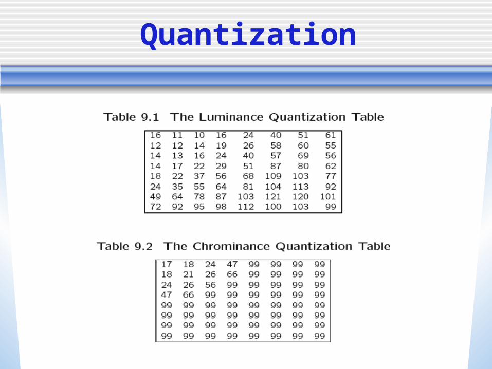
• Use larger entries in Q for the higher spatial frequencies These are entries to the lower right part
of the matrix The following slide shows the default Q(u,
v) values for luminance and chrominance Based on psychophysical studies intended to
maximize compression ratios while minimizing perceptual distortion
Since after division the entries are smaller, we can use fewer bits to encode them
Quantization

Quantization
• Multiple quantization matrices can be used (perhaps by scaling the defaults), allowing the user to choose how much compression to use Trades off quality vs. compression ratio More compression means larger entries
in Q An example of JPEG coding and decoding
on one image block is shown next

Original and DCT coded block

Quantized and Reconstructed Blocks

After IDCT and Difference from Original

Same steps on a less homogeneous block

Steps 2 and 3

IDCT and Difference

Preparation for Entropy Coding
• We have seen two main steps in JPEG coding: DCT and quantization
• The remaining steps all lead up to entropy coding of the quantized DCT coefficients These additional data compression steps
are lossless Most of the lossiness is in the
quantization step

Run-Length Coding
• We now do run-length coding The AC and DC components are treated
differently Since after quantization we have many
0 AC components, RLC is a good idea Note that most of the zero components
are towards the lower right corner (high spatial frequencies)
To take advantage of this, use zigzag scanning to create a 64-vector

Zigzag Scan in JPEG

Run-Length Coding
• Now the RLC step replaces values in a 64-vector (previously an 8x8 block) by a pair (RUNLENGTH, VALUE), where RUNLENGTH is the number of zeroes in the run and VALUE is the next non-zero value From the first example we have (32, 6, -1, -1,
0, -1, 0, 0, 0, -1, 0, 0, 1, 0, 0, …, 0) This becomes (0,6) (0,-1)(1,-1)(3,-1)(2,1)(0,0) -
Note that DC coefficient is ignored

Coding of DC Coefficients
• Now we handle the DC coefficients 1 DC per block DC coefficients may vary greatly over the
whole image, but slowly from one block to its neighbor (once again, zigzag order)
So apply Differential Pulse Code Modulation (DPCM) for the DC coefficients
If the first five DC coefficients are 150, 155, 149, 152, 144, we come up with DPCM code- 150, 5, -6, 3, -8
Entropy Coding
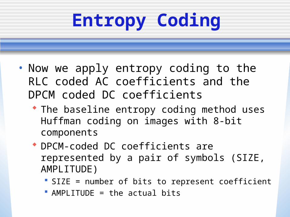
• Now we apply entropy coding to the RLC coded AC coefficients and the DPCM coded DC coefficients The baseline entropy coding method uses
Huffman coding on images with 8-bit components
DPCM-coded DC coefficients are represented by a pair of symbols (SIZE, AMPLITUDE) SIZE = number of bits to represent coefficient AMPLITUDE = the actual bits
Entropy Coding
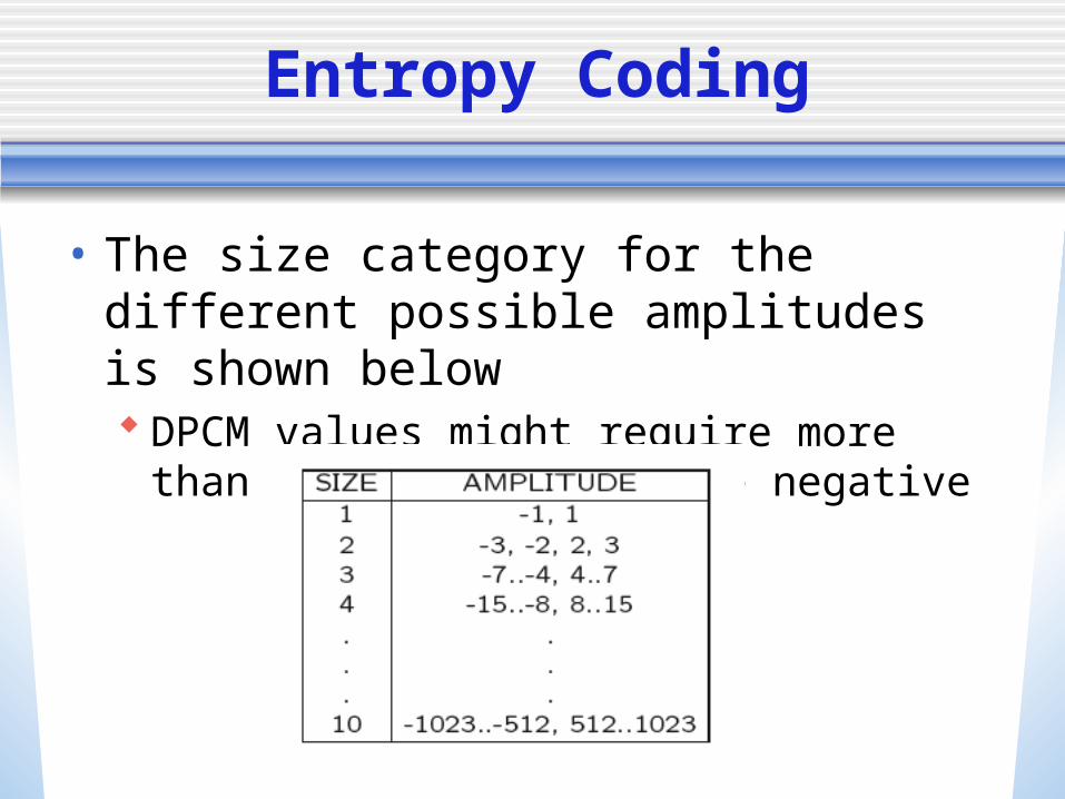
• The size category for the different possible amplitudes is shown below DPCM values might require more than 8
bits and might be negative

Entropy Coding
One’s complement is used for negative numbers
Codes 150, 5, -6, 3, -8 become (8, 10010110), (3, 101), (2, 11), (4,
0111) Now the SIZE is Huffman coded
Expect lots of small SIZEs
AMPLITUDE is not Huffman coded Pretty uniform distribution expected, so
probably not worth while

Huffman Coding for AC Coefficients
• AC coefficients have been RL coded and represented by symbol pairs (RUNLENGTH, VALUE) VALUE is really a (SIZE, AMPLITUDE) pair
RUNLENGTH and SIZE are each 4-bit values stored in a single byte - Symbol1• For runs greater than 15, special code (15, 0) is
used
Symbol2 is the AMPLITUDE Symbol1 is run-length coded, Symbol 2 is not

JPEG Modes
• JPEG supports several different modes Sequential Mode Progresssive Mode Hierarchical Mode Lossless Mode
• Sequential is the default mode Each image component is encoded in a
single left-to-right, top-to-bottom scan This is the mode we have been describing

Progressive Mode
• Progressive mode delivers low-quality versions of the image quickly, and then fills in the details in successive passes
• This is useful for web browsers, where the image download might take a long time The user gets an approximate image quickly Can be done by sending the DC coefficient and
a few AC coefficients first Next send some more (low spatial resolution)
AC coefficients, and continue in this way until all of the coefficients have been sent

Sequential vs. Progressive

Hierarchical Mode
• Hierarchical mode encodes the image at several different resolutions
• These resolutions can be transmitted in multiple passes with increased resolution at each pass
• The process is described in the following slides

Hierarchical Mode

Hierarchical Mode

Hierarchical Mode

JPEG Bitstream
• The JPEG hierarchical organization is described in the next slide Frame is a picture Scan is a picture component Segment is a group of blocks Frame header inlcudes
Bits per pixel Size of image Quantization table etc.
Scan header includes Number of components Huffman coding tables, etc.

JPEG Bitstream
JPEG2000
• JPEG2000 (extension jp2) is the latest series of standards from the JPEG committee Uses wavelet technology Better compression than JPG Superior lossless compression Supports large images and images with many
components Region-of-interest coding Compound documents Computer-generated imagery Other improvements over JPG

Region-of-Interest Coding
JBIG
• JBIG (Joint Bi-Level Image Processing Group) is a standard for coding binary images Faxes, scanned documents, etc. These have characteristics different from
color/greyscale images which lend themselves to different coding techniques
JBIG - lossless coding JBIG2 - both, lossless and lossy
Model-based coding