Embed Size (px)
Citation preview
JPEG2000 Standalone DVR User Guide
- 1 -
Date: 2006/12/20 VER: 1.60
Caution ……………………………………………………………………. 3
Package ……………………………………………………………………. 3
Specification ……………………………………………………………………. 4
CHAP.1 Appearance
1-1 Front panel introduction ……………………………………………………………………. 6
1-2 Back panel introduction ……………………………………………………………………. 8
1-3 IR remote controller introduction ……………………………………………………………………. 9
CHAP.2 Installation
2-1 Camera and monitor installation ……………………………………………………………………. 10
2-2 Sensor and alarm installation ……………………………………………………………………. 11
2-3 Network and serial port installation ……………………………………………………………………. 12
2-4 HDD installation ……………………………………………………………………. 14
2-5 Power plugging ……………………………………………………………………. 15
CHAP.3 Operation
3-1 Display configuration ……………………………………………………………………. 16
3-2 Screen switch ……………………………………………………………………. 17
3-3 PIP view ……………………………………………………………………. 17
3-4 Freeze view ……………………………………………………………………. 17
3-5 View in sequence ……………………………………………………………………. 18
3-6 Zoom view ……………………………………………………………………. 19
3-7 Keylock ……………………………………………………………………. 19
3-8 switch audio channel ……………………………………………………………………. 19
3-9 Record ……………………………………………………………………. 20
3-10 Playback ……………………………………………………………………. 21
CHAP.4 Set up
4-1 Log-in ……………………………………………………………………. 24
4-2 Display setup ……………………………………………………………………. 25
4-3 Configuration ……………………………………………………………………. 26
4-4 Record setup ……………………………………………………………………. 34
4-5 Bak-up ……………………………………………………………………. 37
4-6 External device ……………………………………………………………………. 38
4-7 Factory default ……………………………………………………………………. 43
4-8 Language ……………………………………………………………………. 43
CONTENTS
JPEG2000 Standalone DVR User Guide
- 2 -
Disclaimer: The product names mentioned in this manual are used as identifications only, while the copyright of these names
might belong to other companies.
The product spec and info are for reference only, and they may be updated from time to time without notification.
CHAP.5 Back-up 5-1 Data backup …………………………………………………………………… 44
5-2 Backup player software installation …………………………………………………………………… 45
5-3 Backup player software interface …………………………………………………………………… 46
CHAP.6 PTZ camera control
6-1 PTZ camera installation …………………………………………………………………… 48
6-2 PTZ camera operation …………………………………………………………………… 49
CHAP.7 Network & remote software
7-1 Network configuration …………………………………………………………………… 50
7-2 Network installation and setup …………………………………………………………………… 50
7-3 Router setup …………………………………………………………………… 53
7-4 Client software …………………………………………………………………… 55
7-5 DDNS setup and operation …………………………………………………………………… 63
Appendix
1. Record time table …………………………………………………………………… 73
2. System configuration …………………………………………………………………… 75
3. Firmware upgrade …………………………………………………………………… 76
4. Play only mode …………………………………………………………………… 80
JPEG2000 Standalone DVR User Guide
- 3 -
For you safety, unplug the power before moving the DVR, installing, or replacing any parts or hard drive.
Make sure all the power cable and wires are properly set up before using the DVR. Contact your distributor
immediately if there is any defect.
To avoid a short circuit, don’t leave any unnecessary parts inside the DVR.
Please avoid dramatic changes of the environment, such as dust, temperature, and humidity. Keep the DVR in a
temperature ranging from 5℃~40℃.
Keep the DVR in a well-ventilated place and away from any heat-generating objects.
Do not block the DVR’s fan and vent.
Do not expose this unit to the sun directly.
If you are not sure of the installation and setup, please consult the technicians.
If there’s any damage to this unit or the power supply, don’t fix it yourself. Consult the technician or the distributor.
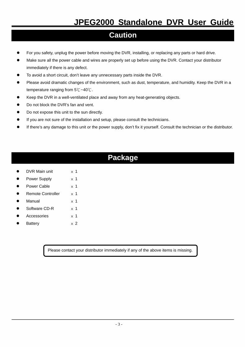
DVR Main unit × 1
Power Supply × 1
Power Cable × 1
Remote Controller × 1
Manual × 1
Software CD-R × 1
Accessories × 1
Battery × 2
Caution
Package
Please contact your distributor immediately if any of the above items is missing.
JPEG2000 Standalone DVR User Guide
- 4 -
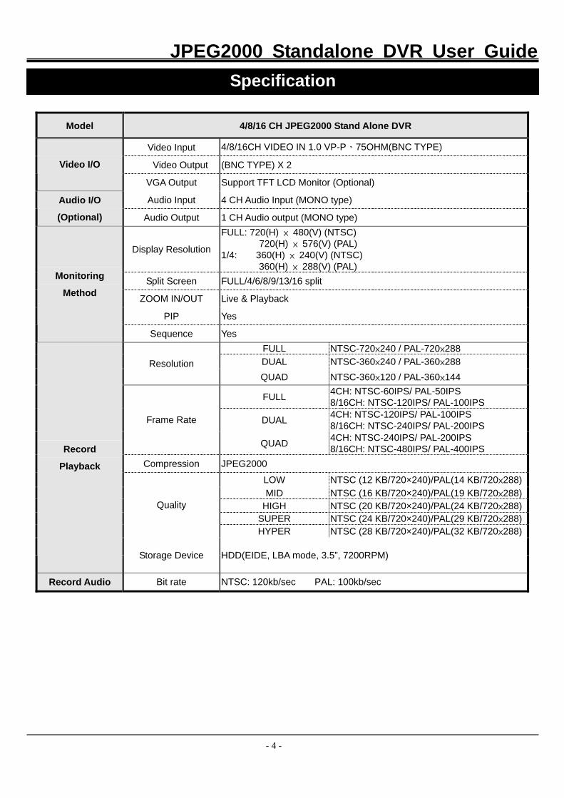
Model 4/8/16 CH JPEG2000 Stand Alone DVR
Video Input 4/8/16CH VIDEO IN 1.0 VP-P,75OHM(BNC TYPE)
Video Output (BNC TYPE) X 2 Video I/O
VGA Output Support TFT LCD Monitor (Optional)
Audio Input 4 CH Audio Input (MONO type) Audio I/O
(Optional) Audio Output 1 CH Audio output (MONO type)
Display Resolution
FULL: 720(H) × 480(V) (NTSC) 720(H) × 576(V) (PAL)
1/4: 360(H) × 240(V) (NTSC) 360(H) × 288(V) (PAL)
Split Screen FULL/4/6/8/9/13/16 split
ZOOM IN/OUT Live & Playback
PIP Yes
Monitoring
Method
Sequence Yes FULL NTSC-720×240 / PAL-720×288 DUAL NTSC-360×240 / PAL-360×288 Resolution QUAD NTSC-360×120 / PAL-360×144
FULL 4CH: NTSC-60IPS/ PAL-50IPS 8/16CH: NTSC-120IPS/ PAL-100IPS
DUAL 4CH: NTSC-120IPS/ PAL-100IPS 8/16CH: NTSC-240IPS/ PAL-200IPS Frame Rate
QUAD 4CH: NTSC-240IPS/ PAL-200IPS 8/16CH: NTSC-480IPS/ PAL-400IPS
Compression JPEG2000
LOW NTSC (12 KB/720×240)/PAL(14 KB/720×288)MID NTSC (16 KB/720×240)/PAL(19 KB/720×288)
HIGH NTSC (20 KB/720×240)/PAL(24 KB/720×288)SUPER NTSC (24 KB/720×240)/PAL(29 KB/720×288)
Quality
HYPER NTSC (28 KB/720×240)/PAL(32 KB/720×288)
Record
Playback
Storage Device HDD(EIDE, LBA mode, 3.5”, 7200RPM)
Record Audio Bit rate NTSC: 120kb/sec PAL: 100kb/sec
Specification
JPEG2000 Standalone DVR User Guide
- 5 -
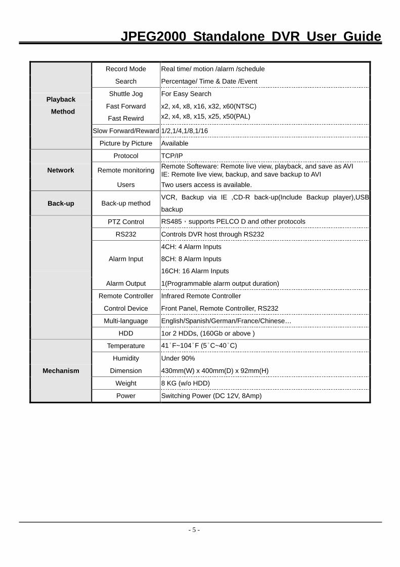
Record Mode Real time/ motion /alarm /schedule
Search Percentage/ Time & Date /Event
Shuttle Jog For Easy Search
Fast Forward
Fast Rewird
x2, x4, x8, x16, x32, x60(NTSC) x2, x4, x8, x15, x25, x50(PAL)
Slow Forward/Reward 1/2,1/4,1/8,1/16
Playback
Method
Picture by Picture Available
Protocol TCP/IP
Remote monitoring Remote Softeware: Remote live view, playback, and save as AVI IE: Remote live view, backup, and save backup to AVI Network
Users Two users access is available.
Back-up Back-up method VCR, Backup via IE ,CD-R back-up(Include Backup player),USB
backup
PTZ Control RS485,supports PELCO D and other protocols
RS232 Controls DVR host through RS232
Alarm Input
4CH: 4 Alarm Inputs
8CH: 8 Alarm Inputs
16CH: 16 Alarm Inputs
Alarm Output 1(Programmable alarm output duration)
Remote Controller Infrared Remote Controller
Control Device Front Panel, Remote Controller, RS232
Multi-language English/Spanish/German/France/Chinese…
HDD 1or 2 HDDs, (160Gb or above )
Temperature 41°F~104°F (5°C~40°C)
Humidity Under 90%
Dimension 430mm(W) x 400mm(D) x 92mm(H)
Weight 8 KG (w/o HDD)
Mechanism
Power Switching Power (DC 12V, 8Amp)
JPEG2000 Standalone DVR User Guide
- 6 -
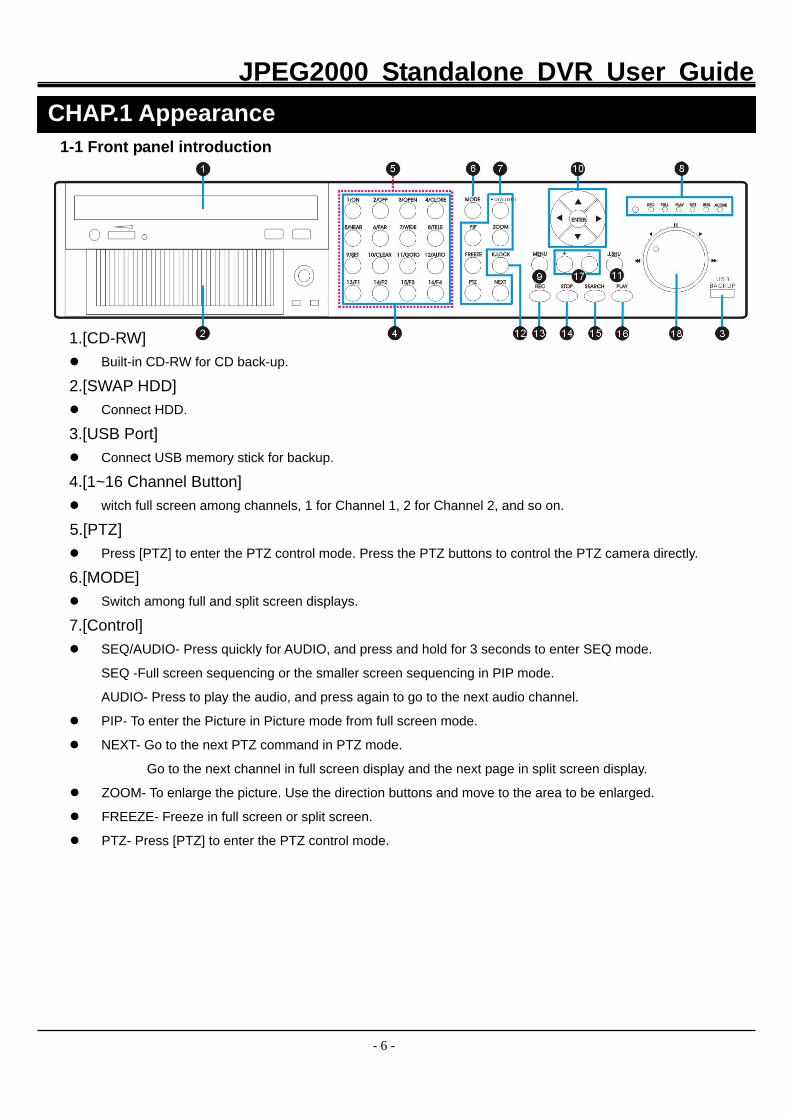
1-1 Front panel introduction
1.[CD-RW] Built-in CD-RW for CD back-up.
2.[SWAP HDD] Connect HDD.
3.[USB Port] Connect USB memory stick for backup.
4.[1~16 Channel Button] witch full screen among channels, 1 for Channel 1, 2 for Channel 2, and so on.
5.[PTZ] Press [PTZ] to enter the PTZ control mode. Press the PTZ buttons to control the PTZ camera directly.
6.[MODE] Switch among full and split screen displays.
7.[Control] SEQ/AUDIO- Press quickly for AUDIO, and press and hold for 3 seconds to enter SEQ mode.
SEQ -Full screen sequencing or the smaller screen sequencing in PIP mode.
AUDIO- Press to play the audio, and press again to go to the next audio channel.
PIP- To enter the Picture in Picture mode from full screen mode.
NEXT- Go to the next PTZ command in PTZ mode.
Go to the next channel in full screen display and the next page in split screen display.
ZOOM- To enlarge the picture. Use the direction buttons and move to the area to be enlarged.
FREEZE- Freeze in full screen or split screen.
PTZ- Press [PTZ] to enter the PTZ control mode.
CHAP.1 Appearance
JPEG2000 Standalone DVR User Guide
- 7 -
8.[IR Receiver & LED Lamps] IR Remote Controller Receiver.
DVR Status LED:
RUN- Flashes when play picture by picture through J. Shuttle.
ACTIVE- On when the J. Shuttle is ready to use.
REC- On while recording and flashes at stand-by mode, such as no motion triggered at the motion record mode
PLAY- On while playback.
FULL- On when HDD storage is full.
NET- On when the DVR is connected remotely.
9.[MENU] Enter the menu and set up.
10.[Directions & ENTER] Directions- Navigate the menu.
ENTER- Confirm the selected options.
11.[J.SHUTTLE Button] Activate the Jog Shuttle and press again to deactivate.
12.[K.LOCK] Lock the buttons on front panel.
13.[REC] To activate Emergency Record at continuous, Super fine quality and Best resolution. Press STOP to exit the
Emergency Record mode.
14.[STOP] Stop the emergency record and return to the record schedule programmed in the Record Setup.
Stop playback and return to the LIVE mode.
15.[SEARCH] Enter the Search dialog window to search by percentage, date / time, or the event list.
16.[PLAY] Play the recorded data beginning from the end of previous playback.
17.[+ / -] Adjust set-up value.
Adjust display orders of channel.
18.[Jog Shuttle] In playback: inner rim to play picture by picture, outer rim to play fast forward and backward. Turn clockwise to
play fast forward, and counterclockwise to play fast backward.
Turn the Jog Shuttle to change values in system set-up.
JPEG2000 Standalone DVR User Guide
- 8 -
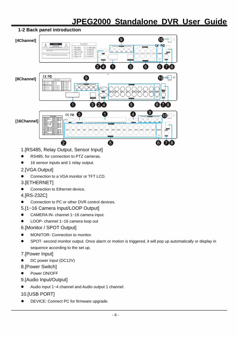
1-2 Back panel introduction [4Channel]
[8Channel]
[16Channel]
1.[RS485, Relay Output, Sensor Input] RS485, for connection to PTZ cameras. 16 sensor inputs and 1 relay output.
2.[VGA Output] Connection to a VGA monitor or TFT LCD.
3.[ETHERNET] Connection to Ethernet device.
4.[RS-232C] Connection to PC or other DVR control devices.
5.[1~16 Camera Input/LOOP Output] CAMERA IN- channel 1~16 camera input. LOOP- channel 1~16 camera loop out
6.[Monitor / SPOT Output] MONITOR- Connection to monitor. SPOT- second monitor output. Once alarm or motion is triggered, it will pop up automatically or display in
sequence according to the set up. 7.[Power Input]
DC power input (DC12V) 8.[Power Switch]
Power ON/OFF 9.[Audio Input/Output] Audio input 1~4 channel and Audio output 1 channel.
10.[USB PORT] DEVICE: Connect PC for firmware upgrade.
JPEG2000 Standalone DVR User Guide
- 9 -
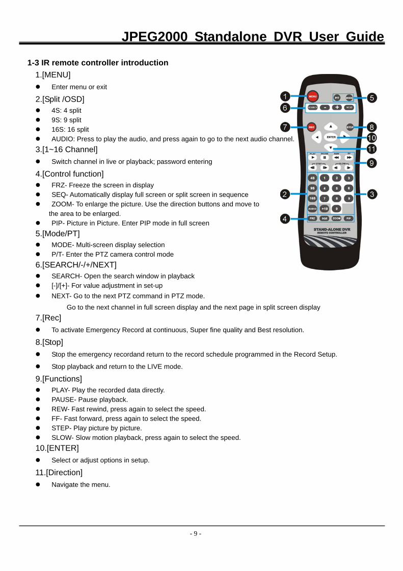
1-3 IR remote controller introduction
1.[MENU] Enter menu or exit
2.[Split /OSD] 4S: 4 split 9S: 9 split 16S: 16 split AUDIO: Press to play the audio, and press again to go to the next audio channel.
3.[1~16 Channel] Switch channel in live or playback; password entering
4.[Control function] FRZ- Freeze the screen in display SEQ- Automatically display full screen or split screen in sequence ZOOM- To enlarge the picture. Use the direction buttons and move to
the area to be enlarged. PIP- Picture in Picture. Enter PIP mode in full screen
5.[Mode/PT] MODE- Multi-screen display selection P/T- Enter the PTZ camera control mode
6.[SEARCH/-/+/NEXT] SEARCH- Open the search window in playback [-]/[+]- For value adjustment in set-up NEXT- Go to the next PTZ command in PTZ mode.
Go to the next channel in full screen display and the next page in split screen display 7.[Rec]
To activate Emergency Record at continuous, Super fine quality and Best resolution.
8.[Stop] Stop the emergency recordand return to the record schedule programmed in the Record Setup.
Stop playback and return to the LIVE mode.
9.[Functions] PLAY- Play the recorded data directly. PAUSE- Pause playback. REW- Fast rewind, press again to select the speed. FF- Fast forward, press again to select the speed. STEP- Play picture by picture. SLOW- Slow motion playback, press again to select the speed.
10.[ENTER] Select or adjust options in setup.
11.[Direction] Navigate the menu.
JPEG2000 Standalone DVR User Guide
- 10 -
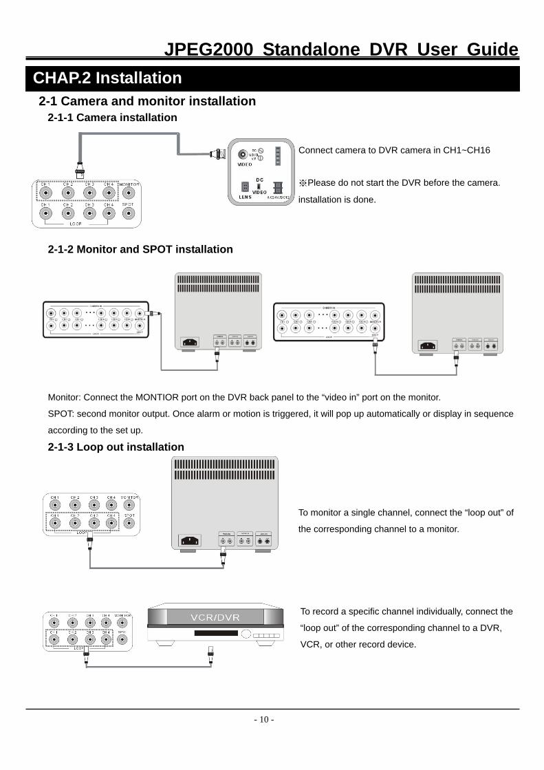
2-1 Camera and monitor installation 2-1-1 Camera installation
Connect camera to DVR camera in CH1~CH16
※Please do not start the DVR before the camera.
installation is done.
2-1-2 Monitor and SPOT installation
Monitor: Connect the MONTIOR port on the DVR back panel to the “video in” port on the monitor.
SPOT: second monitor output. Once alarm or motion is triggered, it will pop up automatically or display in sequence
according to the set up.
2-1-3 Loop out installation
To monitor a single channel, connect the “loop out” of
the corresponding channel to a monitor.
To record a specific channel individually, connect the
“loop out” of the corresponding channel to a DVR,
VCR, or other record device.
CHAP.2 Installation
JPEG2000 Standalone DVR User Guide
- 11 -
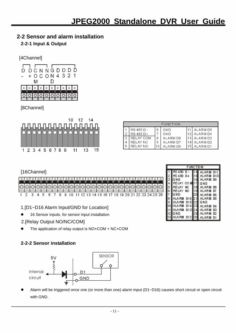
2-2 Sensor and alarm installation
2-2-1 Input & Output
[4Channel]
[8Channel] [16Channel] 1.[D1~D16 Alarm Input/GND for Location] 16 Sensor inputs, for sensor input installation
2.[Relay Output NO/NC/COM] The application of relay output is NO+COM + NC+COM
2-2-2 Sensor installation
Alarm will be triggered once one (or more than one) alarm input (D1~D16) causes short circuit or open circuit
with GND.
JPEG2000 Standalone DVR User Guide
- 12 -
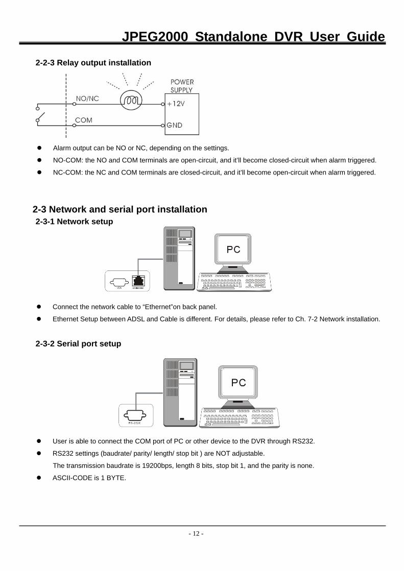
2-2-3 Relay output installation
Alarm output can be NO or NC, depending on the settings.
NO-COM: the NO and COM terminals are open-circuit, and it’ll become closed-circuit when alarm triggered.
NC-COM: the NC and COM terminals are closed-circuit, and it’ll become open-circuit when alarm triggered.
2-3 Network and serial port installation
2-3-1 Network setup
Connect the network cable to “Ethernet”on back panel.
Ethernet Setup between ADSL and Cable is different. For details, please refer to Ch. 7-2 Network installation.
2-3-2 Serial port setup
User is able to connect the COM port of PC or other device to the DVR through RS232.
RS232 settings (baudrate/ parity/ length/ stop bit ) are NOT adjustable.
The transmission baudrate is 19200bps, length 8 bits, stop bit 1, and the parity is none.
ASCII-CODE is 1 BYTE.
JPEG2000 Standalone DVR User Guide
- 13 -
# 2 RxD
# 3 TxD
# 5 GND
TxD # 3
GND # 5
RxD # 2
DVMR unit Other device (PC)
D-SUB 9 cable (twisted RS-232C cable)
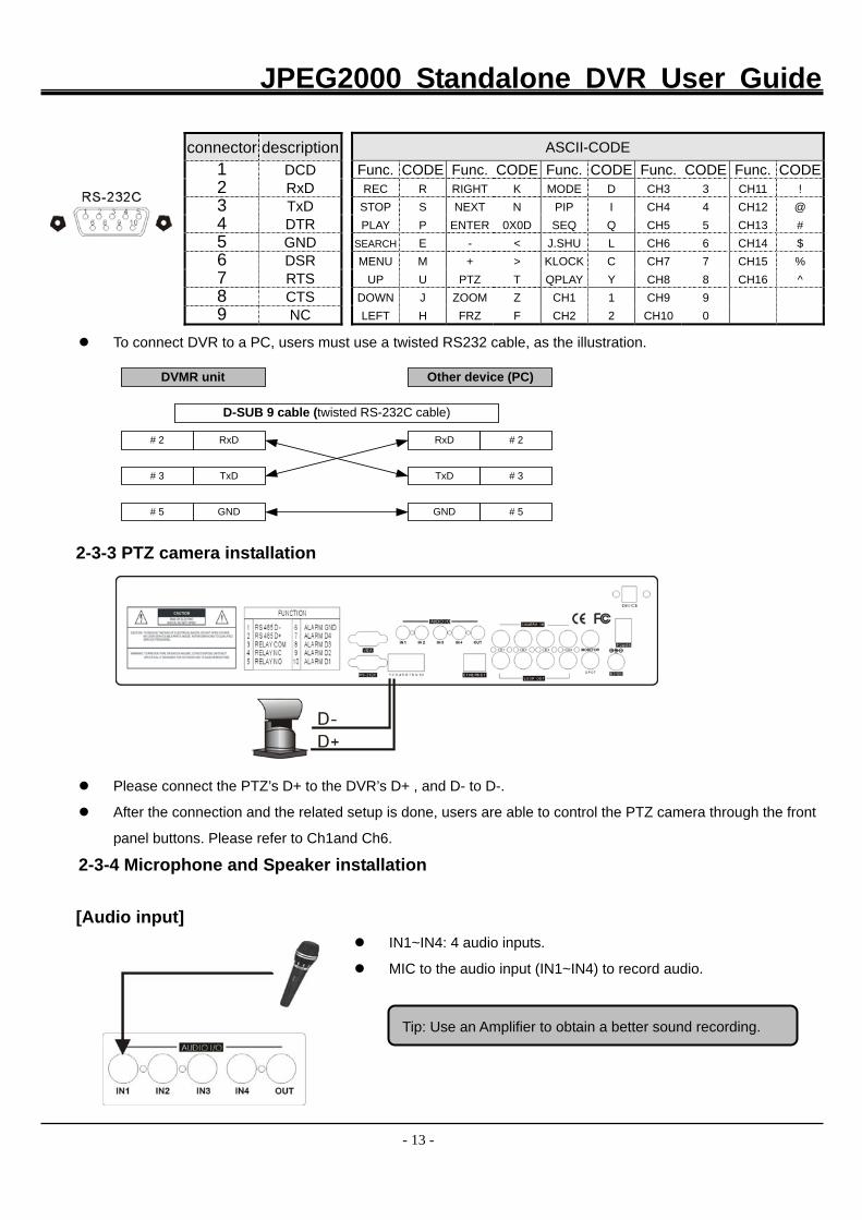
To connect DVR to a PC, users must use a twisted RS232 cable, as the illustration.
2-3-3 PTZ camera installation
Please connect the PTZ’s D+ to the DVR’s D+ , and D- to D-.
After the connection and the related setup is done, users are able to control the PTZ camera through the front
panel buttons. Please refer to Ch1and Ch6.
2-3-4 Microphone and Speaker installation
[Audio input] IN1~IN4: 4 audio inputs.
MIC to the audio input (IN1~IN4) to record audio.
connector description 1 DCD 2 RxD 3 TxD 4 DTR 5 GND 6 DSR 7 RTS 8 CTS 9 NC
ASCII-CODE Func. CODE Func. CODE Func. CODE Func. CODE Func. CODEREC R RIGHT K MODE D CH3 3 CH11 !
STOP S NEXT N PIP I CH4 4 CH12 @ PLAY P ENTER 0X0D SEQ Q CH5 5 CH13 #
SEARCH E - < J.SHU L CH6 6 CH14 $ MENU M + > KLOCK C CH7 7 CH15 %
UP U PTZ T QPLAY Y CH8 8 CH16 ^ DOWN J ZOOM Z CH1 1 CH9 9 LEFT H FRZ F CH2 2 CH10 0
Tip: Use an Amplifier to obtain a better sound recording.
JPEG2000 Standalone DVR User Guide
- 14 -
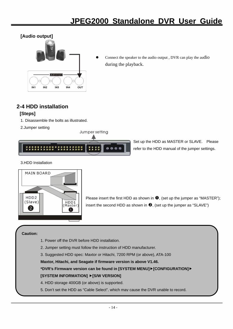
[Audio output]
Connect the speaker to the audio output , DVR can play the audio during the playback.
2-4 HDD installation
[Steps] 1. Disassemble the bolts as illustrated.
2.Jumper setting
Set up the HDD as MASTER or SLAVE. Please
refer to the HDD manual of the jumper settings.
3.HDD Installation
Please insert the first HDD as shown in , (set up the jumper as “MASTER”);
insert the second HDD as shown in , (set up the jumper as “SLAVE”)
Caution:
1. Power off the DVR before HDD installation.
2. Jumper setting must follow the instruction of HDD manufacturer.
3. Suggested HDD spec: Maxtor or Hitachi, 7200 RPM (or above), ATA-100
Maxtor, Hitachi, and Seagate if firmware version is above V1.46.
*DVR’s Firmware version can be found in [SYSTEM MENU] [CONFIGURATION]
[SYSTEM INFORMATION] [S/W VERSION]
4. HDD storage 400GB (or above) is supported.
5. Don’t set the HDD as “Cable Select”, which may cause the DVR unable to record.
JPEG2000 Standalone DVR User Guide
- 15 -
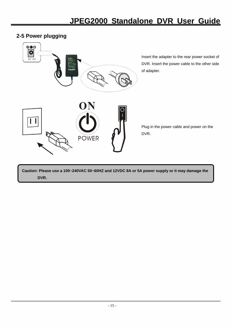
2-5 Power plugging
Insert the adapter to the rear power socket of
DVR. Insert the power cable to the other side
of adapter.
Plug in the power cable and power on the
DVR.
Caution: Please use a 100~240VAC 50~60HZ and 12VDC 8A or 5A power supply or it may damage the
DVR.
JPEG2000 Standalone DVR User Guide
- 16 -
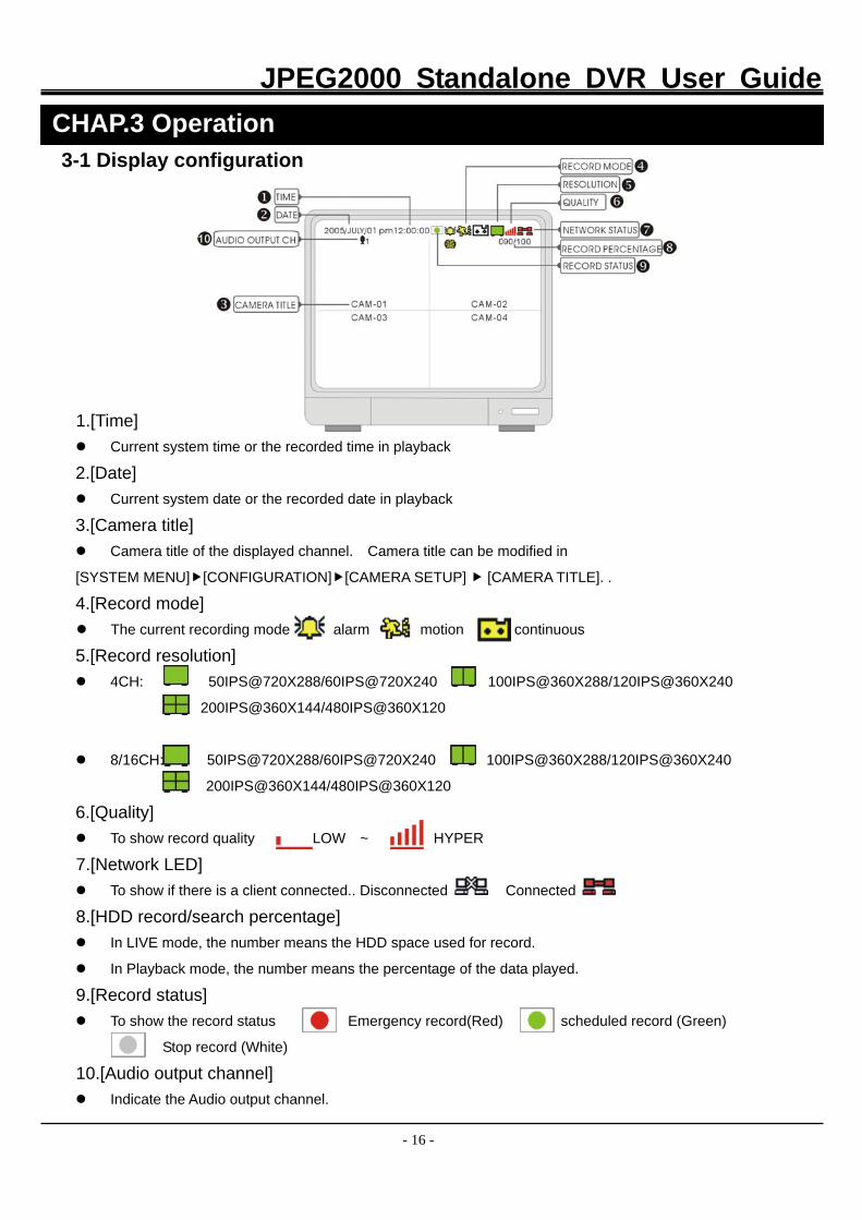
3-1 Display configuration
1.[Time] Current system time or the recorded time in playback
2.[Date] Current system date or the recorded date in playback
3.[Camera title] Camera title of the displayed channel. Camera title can be modified in
[SYSTEM MENU] [CONFIGURATION] [CAMERA SETUP] [CAMERA TITLE]. .
4.[Record mode] The current recording mode alarm motion continuous
5.[Record resolution] 4CH: 50IPS@720X288/60IPS@720X240 100IPS@360X288/120IPS@360X240
200IPS@360X144/480IPS@360X120
8/16CH: 50IPS@720X288/60IPS@720X240 100IPS@360X288/120IPS@360X240
200IPS@360X144/480IPS@360X120
6.[Quality] To show record quality LOW ~ HYPER
7.[Network LED] To show if there is a client connected.. Disconnected Connected
8.[HDD record/search percentage] In LIVE mode, the number means the HDD space used for record.
In Playback mode, the number means the percentage of the data played.
9.[Record status] To show the record status Emergency record(Red) scheduled record (Green)
Stop record (White)
10.[Audio output channel] Indicate the Audio output channel.
CHAP.3 Operation
JPEG2000 Standalone DVR User Guide
- 17 -
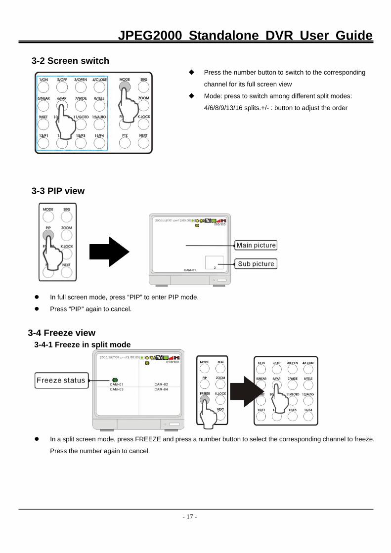
3-2 Screen switch Press the number button to switch to the corresponding
channel for its full screen view
Mode: press to switch among different split modes:
4/6/8/9/13/16 splits.+/- : button to adjust the order
3-3 PIP view
In full screen mode, press “PIP” to enter PIP mode.
Press “PIP” again to cancel.
3-4 Freeze view 3-4-1 Freeze in split mode
In a split screen mode, press FREEZE and press a number button to select the corresponding channel to freeze.
Press the number again to cancel.
JPEG2000 Standalone DVR User Guide
- 18 -
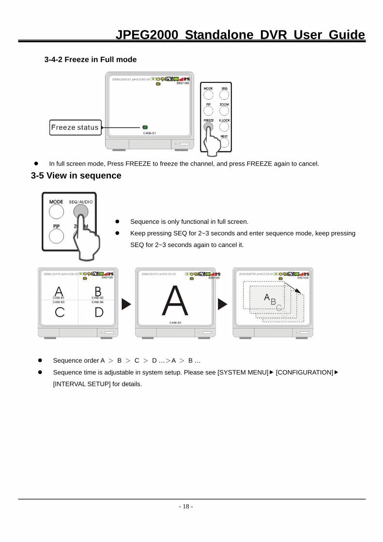
3-4-2 Freeze in Full mode
In full screen mode, Press FREEZE to freeze the channel, and press FREEZE again to cancel.
3-5 View in sequence
Sequence is only functional in full screen.
Keep pressing SEQ for 2~3 seconds and enter sequence mode, keep pressing
SEQ for 2~3 seconds again to cancel it.
Sequence order A > B > C > D …>A > B …
Sequence time is adjustable in system setup. Please see [SYSTEM MENU] [CONFIGURATION]
[INTERVAL SETUP] for details.
JPEG2000 Standalone DVR User Guide
- 19 -
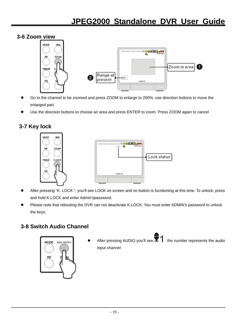
3-6 Zoom view
Go to the channel to be zoomed and press ZOOM to enlarge to 200%, use direction buttons to move the
enlarged part.
Use the direction buttons to choose an area and press ENTER to zoom. Press ZOOM again to cancel
3-7 Key lock
After pressing “K. LOCK “, you’ll see LOCK on screen and no button is fucntioning at this time. To unlock, press
and hold K.LOCK and enter Admin’spassword.
Please note that rebooting the DVR can not deactivate K.LOCK. You must enter ADMIN’s password to unlock
the keys.
3-8 Switch Audio Channel
After pressing AUDIO you’ll see, the number represents the audio
input channel
JPEG2000 Standalone DVR User Guide
- 20 -
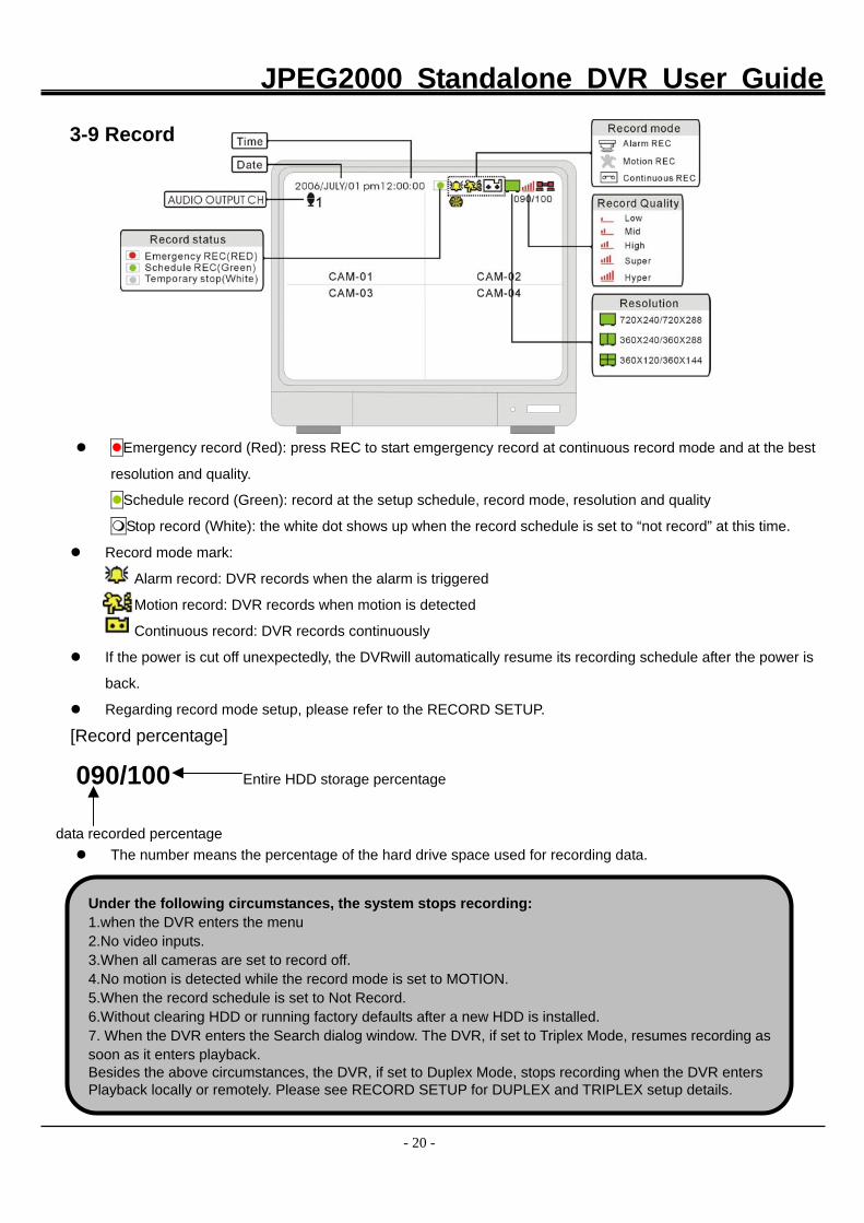
3-9 Record
Emergency record (Red): press REC to start emgergency record at continuous record mode and at the best
resolution and quality.
Schedule record (Green): record at the setup schedule, record mode, resolution and quality
Stop record (White): the white dot shows up when the record schedule is set to “not record” at this time.
Record mode mark:
Alarm record: DVR records when the alarm is triggered
Motion record: DVR records when motion is detected
Continuous record: DVR records continuously
If the power is cut off unexpectedly, the DVRwill automatically resume its recording schedule after the power is
back.
Regarding record mode setup, please refer to the RECORD SETUP.
[Record percentage]
090/100 Entire HDD storage percentage
data recorded percentage
The number means the percentage of the hard drive space used for recording data.
Under the following circumstances, the system stops recording: 1.when the DVR enters the menu 2.No video inputs. 3.When all cameras are set to record off. 4.No motion is detected while the record mode is set to MOTION. 5.When the record schedule is set to Not Record. 6.Without clearing HDD or running factory defaults after a new HDD is installed. 7. When the DVR enters the Search dialog window. The DVR, if set to Triplex Mode, resumes recording assoon as it enters playback. Besides the above circumstances, the DVR, if set to Duplex Mode, stops recording when the DVR enters Playback locally or remotely. Please see RECORD SETUP for DUPLEX and TRIPLEX setup details.
JPEG2000 Standalone DVR User Guide
- 21 -
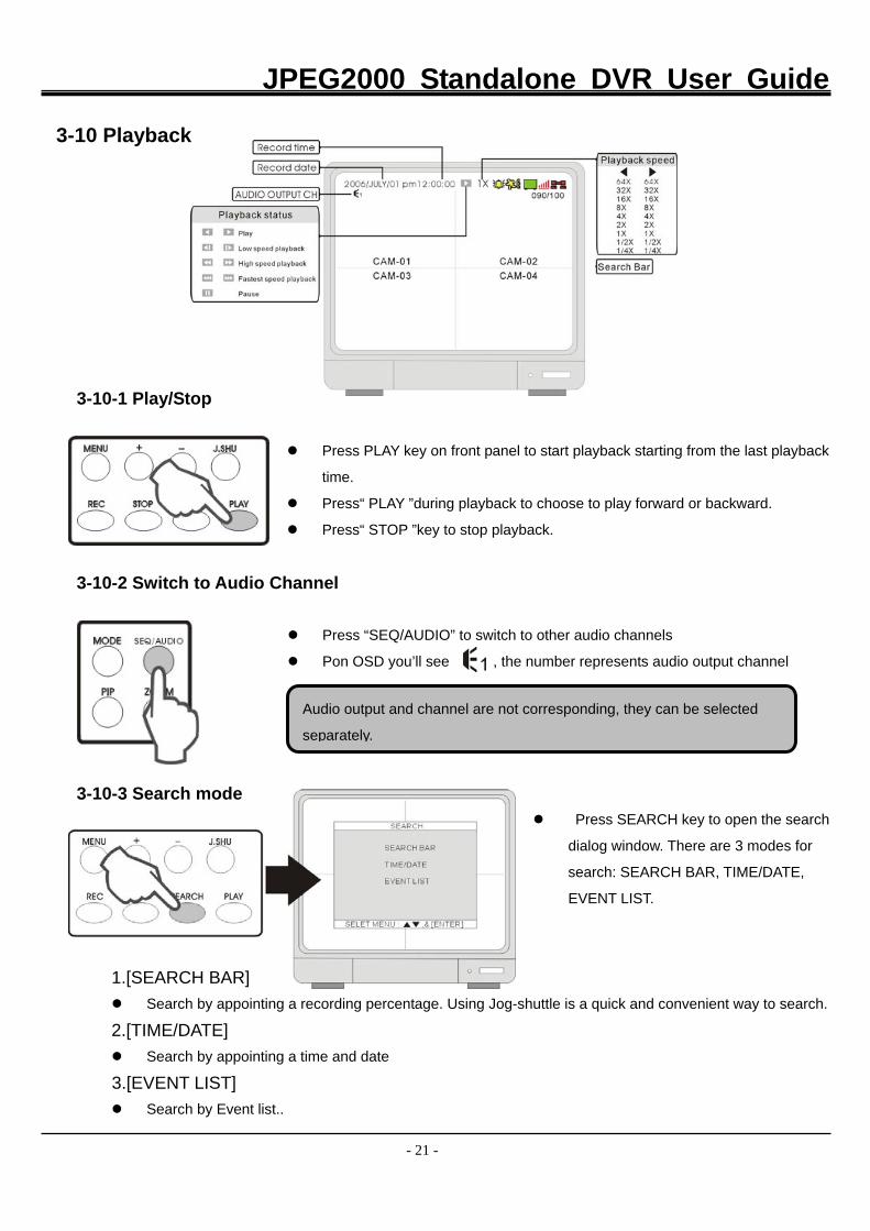
3-10 Playback
3-10-1 Play/Stop
Press PLAY key on front panel to start playback starting from the last playback
time.
Press“ PLAY ”during playback to choose to play forward or backward.
Press“ STOP ”key to stop playback.
3-10-2 Switch to Audio Channel
Press “SEQ/AUDIO” to switch to other audio channels
Pon OSD you’ll see , the number represents audio output channel
3-10-3 Search mode
Press SEARCH key to open the search
dialog window. There are 3 modes for
search: SEARCH BAR, TIME/DATE,
EVENT LIST.
1.[SEARCH BAR] Search by appointing a recording percentage. Using Jog-shuttle is a quick and convenient way to search.
2.[TIME/DATE] Search by appointing a time and date
3.[EVENT LIST] Search by Event list..
Audio output and channel are not corresponding, they can be selected
separately.
JPEG2000 Standalone DVR User Guide
- 22 -
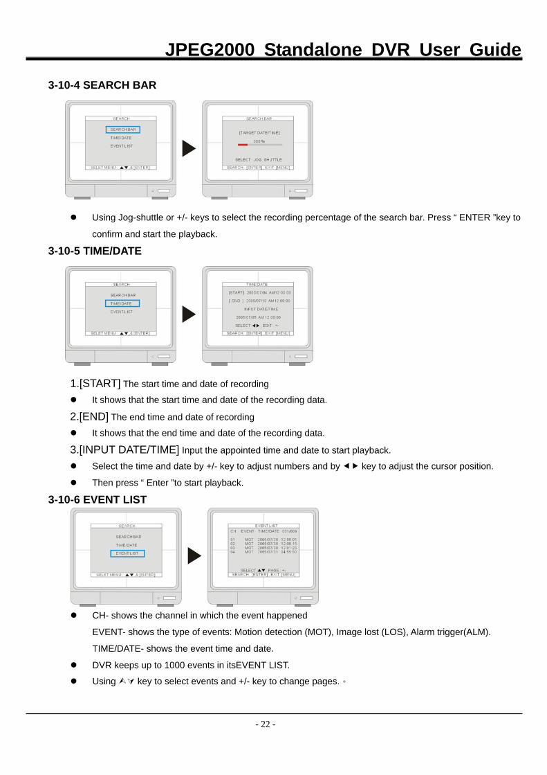
3-10-4 SEARCH BAR
Using Jog-shuttle or +/- keys to select the recording percentage of the search bar. Press “ ENTER ”key to
confirm and start the playback.
3-10-5 TIME/DATE
1.[START] The start time and date of recording
It shows that the start time and date of the recording data.
2.[END] The end time and date of recording
It shows that the end time and date of the recording data.
3.[INPUT DATE/TIME] Input the appointed time and date to start playback.
Select the time and date by +/- key to adjust numbers and by key to adjust the cursor position.
Then press “ Enter ”to start playback.
3-10-6 EVENT LIST
CH- shows the channel in which the event happened
EVENT- shows the type of events: Motion detection (MOT), Image lost (LOS), Alarm trigger(ALM).
TIME/DATE- shows the event time and date.
DVR keeps up to 1000 events in itsEVENT LIST.
Using key to select events and +/- key to change pages.。
JPEG2000 Standalone DVR User Guide
- 23 -
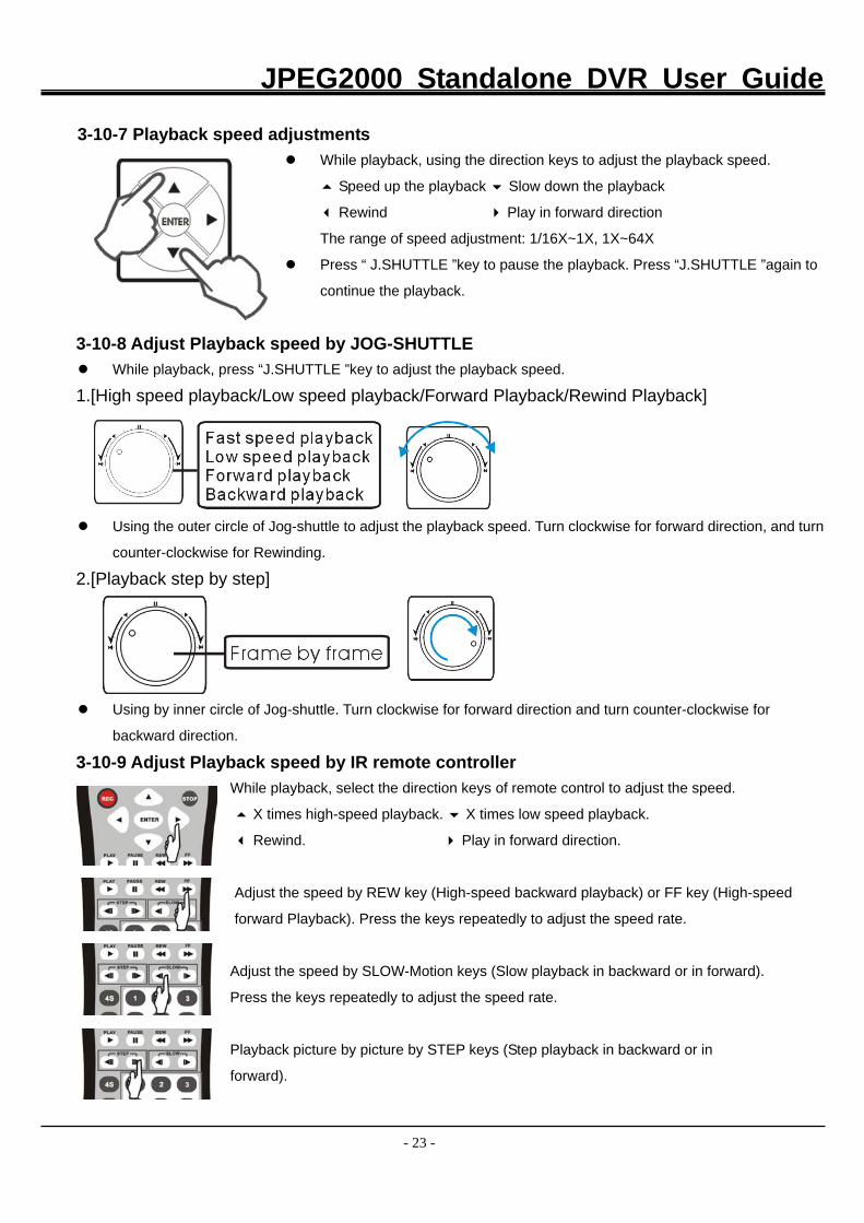
3-10-7 Playback speed adjustments
While playback, using the direction keys to adjust the playback speed.
Speed up the playback Slow down the playback
Rewind Play in forward direction
The range of speed adjustment: 1/16X~1X, 1X~64X
Press “ J.SHUTTLE ”key to pause the playback. Press “J.SHUTTLE ”again to
continue the playback.
3-10-8 Adjust Playback speed by JOG-SHUTTLE
While playback, press “J.SHUTTLE ”key to adjust the playback speed.
1.[High speed playback/Low speed playback/Forward Playback/Rewind Playback]
Using the outer circle of Jog-shuttle to adjust the playback speed. Turn clockwise for forward direction, and turn
counter-clockwise for Rewinding.
2.[Playback step by step]
Using by inner circle of Jog-shuttle. Turn clockwise for forward direction and turn counter-clockwise for
backward direction.
3-10-9 Adjust Playback speed by IR remote controller
While playback, select the direction keys of remote control to adjust the speed.
X times high-speed playback. X times low speed playback.
Rewind. Play in forward direction.
Adjust the speed by REW key (High-speed backward playback) or FF key (High-speed
forward Playback). Press the keys repeatedly to adjust the speed rate.
Adjust the speed by SLOW-Motion keys (Slow playback in backward or in forward).
Press the keys repeatedly to adjust the speed rate.
Playback picture by picture by STEP keys (Step playback in backward or in
forward).
JPEG2000 Standalone DVR User Guide
- 24 -
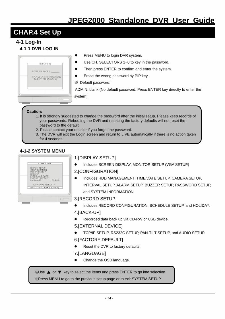
4-1 Log-In 4-1-1 DVR LOG-IN
Press MENU to login DVR system.
Use CH. SELECTORS 1~0 to key in the password.
Then press ENTER to confirm and enter the system.
Erase the wrong password by PIP key.
※ Default password:
ADMIN: blank (No default password. Press ENTER key directly to enter the
system)
4-1-2 SYSTEM MENU
1.[DISPLAY SETUP] Includes SCREEN DISPLAY, MONITOR SETUP (VGA SETUP)
2.[CONFIGURATION] Includes HDD MANAGEMENT, TIME/DATE SETUP, CAMERA SETUP,
INTERVAL SETUP, ALARM SETUP, BUZZER SETUP, PASSWORD SETUP,
and SYSTEM INFORMATION.
3.[RECORD SETUP] Includes RECORD CONFIGURATION, SCHEDULE SETUP, and HOLIDAY.
4.[BACK-UP] Recorded data back up via CD-RW or USB device.
5.[EXTERNAL DEVICE] TCP/IP SETUP, RS232C SETUP, PAN-TILT SETUP, and AUDIO SETUP.
6.[FACTORY DEFAULT] Reset the DVR to factory defaults.
7.[LANGUAGE] Change the OSD language.
CHAP.4 Set Up
Caution: 1. It is strongly suggested to change the password after the initial setup. Please keep records of
your passwords. Rebooting the DVR and resetting the factory defaults will not reset the password to the default.
2. Please contact your reseller if you forget the password. 3. The DVR will exit the Login screen and return to LIVE automatically if there is no action taken
for 4 seconds.
※Use ▲ or ▼ key to select the items and press ENTER to go into selection. ※Press MENU to go to the previous setup page or to exit SYSTEM SETUP.
JPEG2000 Standalone DVR User Guide
- 25 -
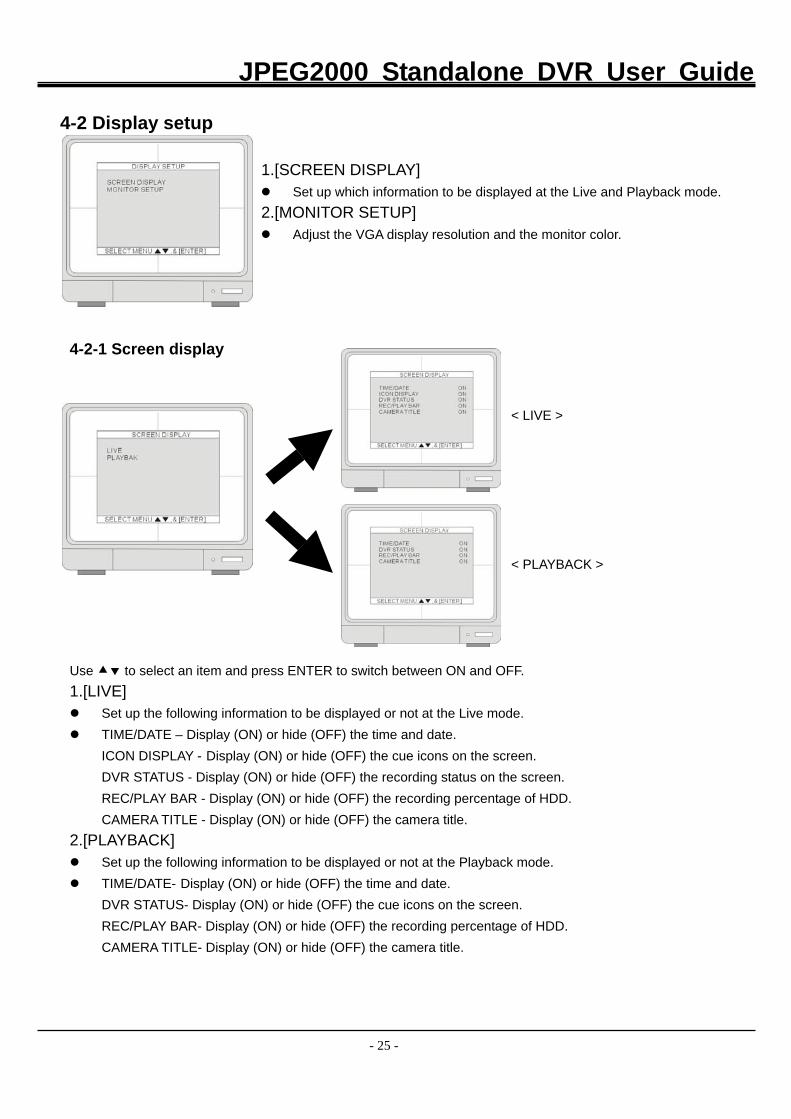
4-2 Display setup
1.[SCREEN DISPLAY] Set up which information to be displayed at the Live and Playback mode.
2.[MONITOR SETUP] Adjust the VGA display resolution and the monitor color.
4-2-1 Screen display
< LIVE > < PLAYBACK >
Use to select an item and press ENTER to switch between ON and OFF. 1.[LIVE] Set up the following information to be displayed or not at the Live mode. TIME/DATE – Display (ON) or hide (OFF) the time and date.
ICON DISPLAY - Display (ON) or hide (OFF) the cue icons on the screen. DVR STATUS - Display (ON) or hide (OFF) the recording status on the screen. REC/PLAY BAR - Display (ON) or hide (OFF) the recording percentage of HDD. CAMERA TITLE - Display (ON) or hide (OFF) the camera title.
2.[PLAYBACK] Set up the following information to be displayed or not at the Playback mode. TIME/DATE- Display (ON) or hide (OFF) the time and date.
DVR STATUS- Display (ON) or hide (OFF) the cue icons on the screen. REC/PLAY BAR- Display (ON) or hide (OFF) the recording percentage of HDD. CAMERA TITLE- Display (ON) or hide (OFF) the camera title.
JPEG2000 Standalone DVR User Guide
- 26 -
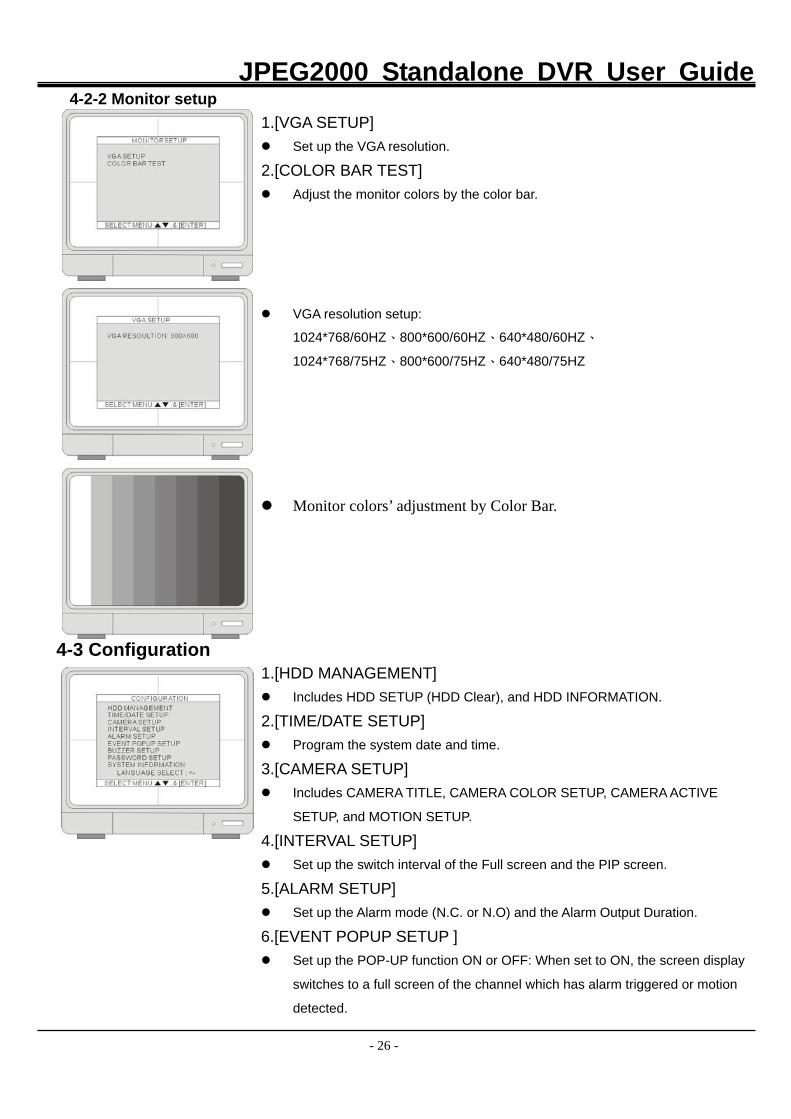
4-2-2 Monitor setup 1.[VGA SETUP]
Set up the VGA resolution.
2.[COLOR BAR TEST] Adjust the monitor colors by the color bar.
VGA resolution setup:
1024*768/60HZ、800*600/60HZ、640*480/60HZ、
1024*768/75HZ、800*600/75HZ、640*480/75HZ
Monitor colors’ adjustment by Color Bar.
4-3 Configuration 1.[HDD MANAGEMENT]
Includes HDD SETUP (HDD Clear), and HDD INFORMATION.
2.[TIME/DATE SETUP] Program the system date and time.
3.[CAMERA SETUP] Includes CAMERA TITLE, CAMERA COLOR SETUP, CAMERA ACTIVE
SETUP, and MOTION SETUP.
4.[INTERVAL SETUP] Set up the switch interval of the Full screen and the PIP screen.
5.[ALARM SETUP] Set up the Alarm mode (N.C. or N.O) and the Alarm Output Duration.
6.[EVENT POPUP SETUP ] Set up the POP-UP function ON or OFF: When set to ON, the screen display
switches to a full screen of the channel which has alarm triggered or motion
detected.
JPEG2000 Standalone DVR User Guide
- 27 -
7.[BUZZER SETUP] Set the Buzzer ON or OFF at a certain condition.
8.[PASSWORD SETUP] Setup the password.
9.[SYSTEM INFORMATION] Show the system information, such as the versions of S/W and H/W, HDD
model number, and CD-R model number.
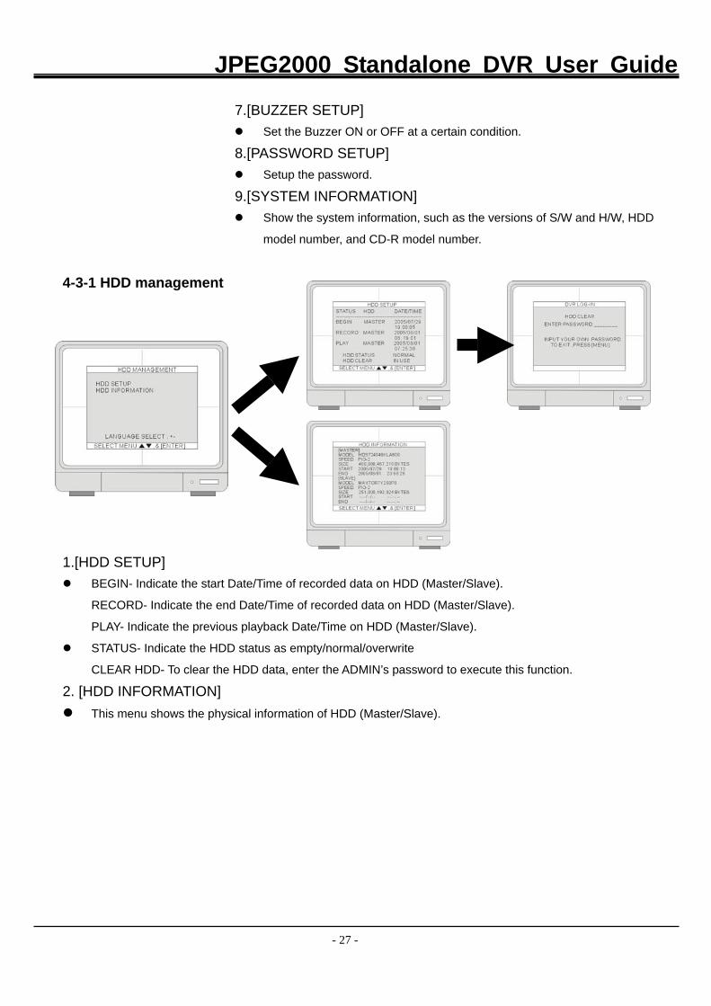
4-3-1 HDD management 1.[HDD SETUP]
BEGIN- Indicate the start Date/Time of recorded data on HDD (Master/Slave).
RECORD- Indicate the end Date/Time of recorded data on HDD (Master/Slave).
PLAY- Indicate the previous playback Date/Time on HDD (Master/Slave).
STATUS- Indicate the HDD status as empty/normal/overwrite
CLEAR HDD- To clear the HDD data, enter the ADMIN’s password to execute this function.
2. [HDD INFORMATION] This menu shows the physical information of HDD (Master/Slave).
JPEG2000 Standalone DVR User Guide
- 28 -
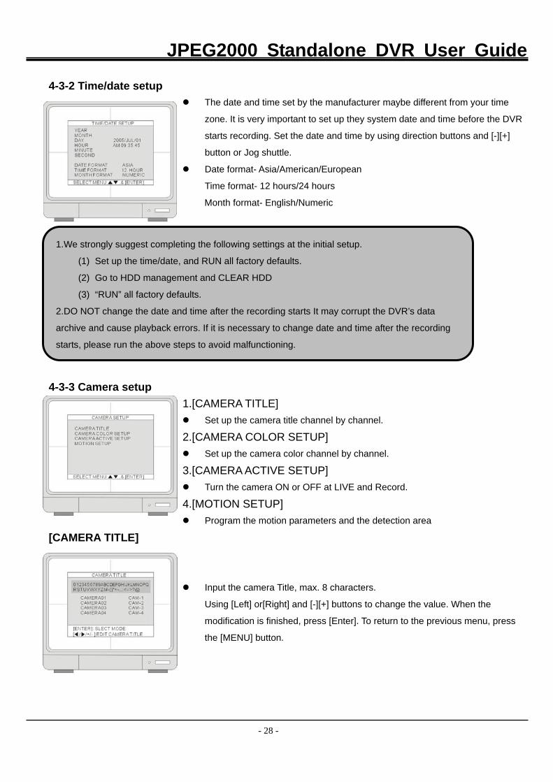
4-3-2 Time/date setup The date and time set by the manufacturer maybe different from your time
zone. It is very important to set up they system date and time before the DVR
starts recording. Set the date and time by using direction buttons and [-][+]
button or Jog shuttle.
Date format- Asia/American/European
Time format- 12 hours/24 hours
Month format- English/Numeric
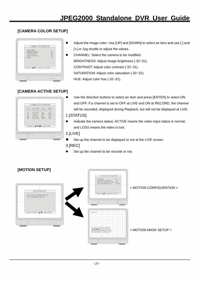
4-3-3 Camera setup 1.[CAMERA TITLE]
Set up the camera title channel by channel.
2.[CAMERA COLOR SETUP] Set up the camera color channel by channel.
3.[CAMERA ACTIVE SETUP] Turn the camera ON or OFF at LIVE and Record.
4.[MOTION SETUP] Program the motion parameters and the detection area
[CAMERA TITLE]
Input the camera Title, max. 8 characters.
Using [Left] or[Right] and [-][+] buttons to change the value. When the
modification is finished, press [Enter]. To return to the previous menu, press
the [MENU] button.
1.We strongly suggest completing the following settings at the initial setup.
(1) Set up the time/date, and RUN all factory defaults.
(2) Go to HDD management and CLEAR HDD
(3) “RUN” all factory defaults.
2.DO NOT change the date and time after the recording starts It may corrupt the DVR’s data
archive and cause playback errors. If it is necessary to change date and time after the recording
starts, please run the above steps to avoid malfunctioning.
JPEG2000 Standalone DVR User Guide
- 29 -
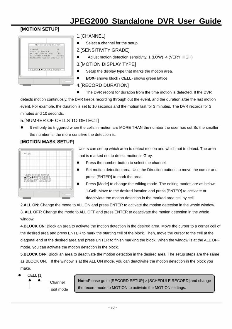
[CAMERA COLOR SETUP]
Adjust the image color: Use [UP] and [DOWN] to select an item and use [-] and
[+] or Jog shuttle to adjust the values.
CHANNEL: Select the camera to be modified.
BRIGHTNESS: Adjust image brightness (-32~31).
CONTRAST: Adjust color contrast (-32~31).
SATURATION: Adjust color saturation (-32~31).
HUE: Adjust color hue (-32~31).
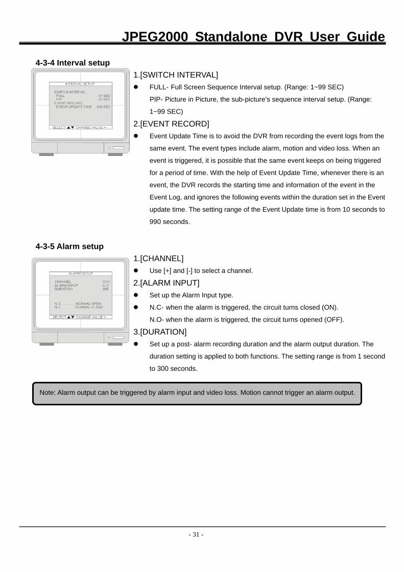
[CAMERA ACTIVE SETUP] Use the direction buttons to select an item and press [ENTER] to select ON
and OFF. If a channel is set to OFF at LIVE and ON at RECORD, the channel
will be recorded, displayed during Playback, but will not be displayed at LIVE.
1.[STATUS] Indicate the camera status: ACTIVE means the video input status is normal,
and LOSS means the video is lost.
2.[LIVE] Set up the channel to be displayed or not at the LIVE screen.
3.[REC] Set up the channel to be recorde or not.
[MOTION SETUP]
< MOTION CONFIGURATION >
< MOTION MASK SETUP >
JPEG2000 Standalone DVR User Guide
- 30 -
[MOTION SETUP] 1.[CHANNEL] Select a channel for the setup.
2.[SENSITIVITY GRADE] Adjust motion detection sensitivity. 1 (LOW)~4 (VERY HIGH)
3.[MOTION DISPLAY TYPE] Setup the display type that marks the motion area.
BOX- shows block / CELL- shows green lattice
4.[RECORD DURATION] The DVR record for duration from the time motion is detected. If the DVR
detects motion continuosly, the DVR keeps recording through out the event, and the duration after the last motion
event. For example, the duration is set to 10 seconds and the motion last for 3 minutes. The DVR records for 3
minutes and 10 seconds.
5.[NUMBER OF CELLS TO DETECT] It will only be triggered when the cells in motion are MORE THAN the number the user has set.So the smaller
the number is, the more sensitive the detection is.
[MOTION MASK SETUP] Users can set up which area to detect motion and which not to detect. The area
that is marked not to detect motion is Grey.
Press the number button to select the channel.
Set motion detection area. Use the Direction buttons to move the cursor and
press [ENTER] to mark the area.
Press [Mode] to change the editing mode. The editing modes are as below:
1.Cell: Move to the desired location and press [ENTER] to activiate or
deactiviate the motion detection in the marked area cell by cell.
2.ALL ON: Change the mode to ALL ON and press ENTER to activate the motion detection in the whole window.
3. ALL OFF: Change the mode to ALL OFF and press ENTER to deactivate the motion detection in the whole
window.
4.BLOCK ON: Block an area to activate the motion detection in the desired area. Move the cursor to a corner cell of
the desired area and press ENTER to mark the starting cell of the block. Then, move the cursor to the cell at the
diagonal end of the desired area and press ENTER to finish marking the block. When the window is at the ALL OFF
mode, you can activate the motion detection in the block.
5.BLOCK OFF: Block an area to deactivate the motion detection in the desired area. The setup steps are the same
as BLOCK ON. If the window is at the ALL ON mode, you can deactivate the motion detection in the block you
make.
CELL [1]
Channel
Edit mode
Note:Please go to [RECORD SETUP] > [SCHEDULE RECORD] and change
the record mode to MOTION to activiate the MOTION settings.
JPEG2000 Standalone DVR User Guide
- 31 -
4-3-4 Interval setup 1.[SWITCH INTERVAL]
FULL- Full Screen Sequence Interval setup. (Range: 1~99 SEC)
PIP- Picture in Picture, the sub-picture’s sequence interval setup. (Range:
1~99 SEC)
2.[EVENT RECORD] Event Update Time is to avoid the DVR from recording the event logs from the
same event. The event types include alarm, motion and video loss. When an
event is triggered, it is possible that the same event keeps on being triggered
for a period of time. With the help of Event Update Time, whenever there is an
event, the DVR records the starting time and information of the event in the
Event Log, and ignores the following events within the duration set in the Event
update time. The setting range of the Event Update time is from 10 seconds to
990 seconds.
4-3-5 Alarm setup 1.[CHANNEL]
Use [+] and [-] to select a channel.
2.[ALARM INPUT] Set up the Alarm Input type.
N.C- when the alarm is triggered, the circuit turns closed (ON).
N.O- when the alarm is triggered, the circuit turns opened (OFF).
3.[DURATION] Set up a post- alarm recording duration and the alarm output duration. The
duration setting is applied to both functions. The setting range is from 1 second
to 300 seconds.
Note: Alarm output can be triggered by alarm input and video loss. Motion cannot trigger an alarm output.
JPEG2000 Standalone DVR User Guide
- 32 -
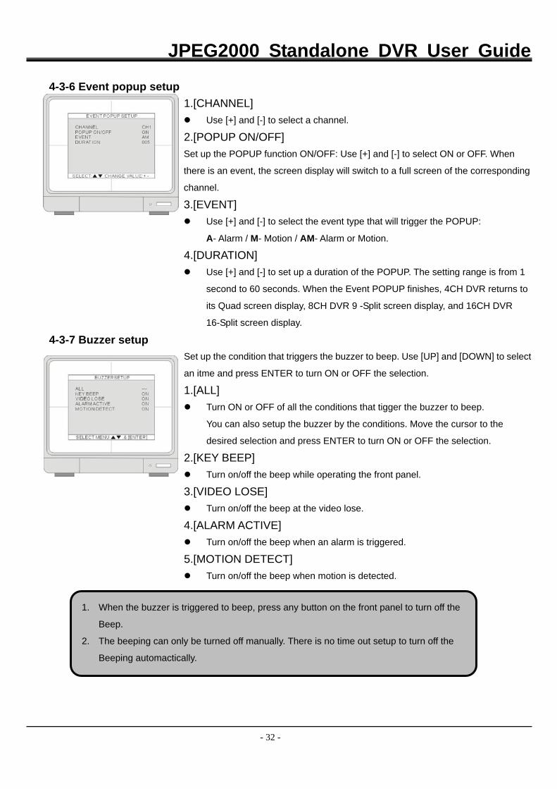
4-3-6 Event popup setup 1.[CHANNEL]
Use [+] and [-] to select a channel.
2.[POPUP ON/OFF] Set up the POPUP function ON/OFF: Use [+] and [-] to select ON or OFF. When
there is an event, the screen display will switch to a full screen of the corresponding
channel.
3.[EVENT] Use [+] and [-] to select the event type that will trigger the POPUP:
A- Alarm / M- Motion / AM- Alarm or Motion.
4.[DURATION] Use [+] and [-] to set up a duration of the POPUP. The setting range is from 1
second to 60 seconds. When the Event POPUP finishes, 4CH DVR returns to
its Quad screen display, 8CH DVR 9 -Split screen display, and 16CH DVR
16-Split screen display.
4-3-7 Buzzer setup
Set up the condition that triggers the buzzer to beep. Use [UP] and [DOWN] to select
an itme and press ENTER to turn ON or OFF the selection.
1.[ALL] Turn ON or OFF of all the conditions that tigger the buzzer to beep.
You can also setup the buzzer by the conditions. Move the cursor to the
desired selection and press ENTER to turn ON or OFF the selection.
2.[KEY BEEP] Turn on/off the beep while operating the front panel.
3.[VIDEO LOSE] Turn on/off the beep at the video lose.
4.[ALARM ACTIVE] Turn on/off the beep when an alarm is triggered.
5.[MOTION DETECT] Turn on/off the beep when motion is detected.
1. When the buzzer is triggered to beep, press any button on the front panel to turn off the
Beep.
2. The beeping can only be turned off manually. There is no time out setup to turn off the
Beeping automactically.
JPEG2000 Standalone DVR User Guide
- 33 -
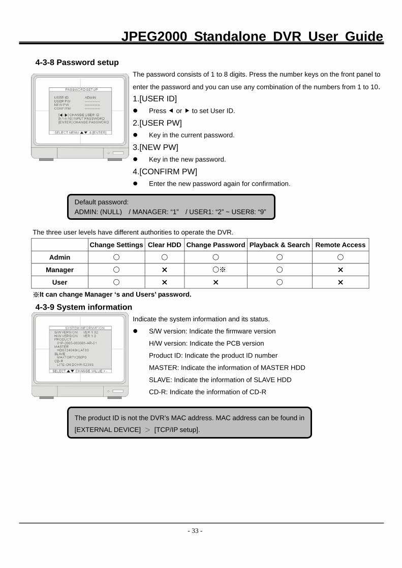
4-3-8 Password setup
The password consists of 1 to 8 digits. Press the number keys on the front panel to
enter the password and you can use any combination of the numbers from 1 to 10. 1.[USER ID] Press or to set User ID.
2.[USER PW] Key in the current password.
3.[NEW PW] Key in the new password.
4.[CONFIRM PW] Enter the new password again for confirmation.
The three user levels have different authorities to operate the DVR.
Change Settings Clear HDD Change Password Playback & Search Remote Access
Admin ○ ○ ○ ○ ○
Manager ○ ○※ ○
User ○ ○
※It can change Manager ‘s and Users’ password.
4-3-9 System information
Indicate the system information and its status.
S/W version: Indicate the firmware version
H/W version: Indicate the PCB version
Product ID: Indicate the product ID number
MASTER: Indicate the information of MASTER HDD
SLAVE: Indicate the information of SLAVE HDD
CD-R: Indicate the information of CD-R
Default password: ADMIN: (NULL) / MANAGER: “1” / USER1: “2” ~ USER8: “9”
The product ID is not the DVR’s MAC address. MAC address can be found in
[EXTERNAL DEVICE] > [TCP/IP setup].
JPEG2000 Standalone DVR User Guide
- 34 -
4-4 Record setup
1.[RECORD CONFIGURATION] Set up overwrite, recording mode, picture quality, resolution, and recording
speed.
2.[SCHEDULE SETUP] Program the recording schedule.
3.[HOLIDAY SETUP] Set up holidays, max. 100 days.
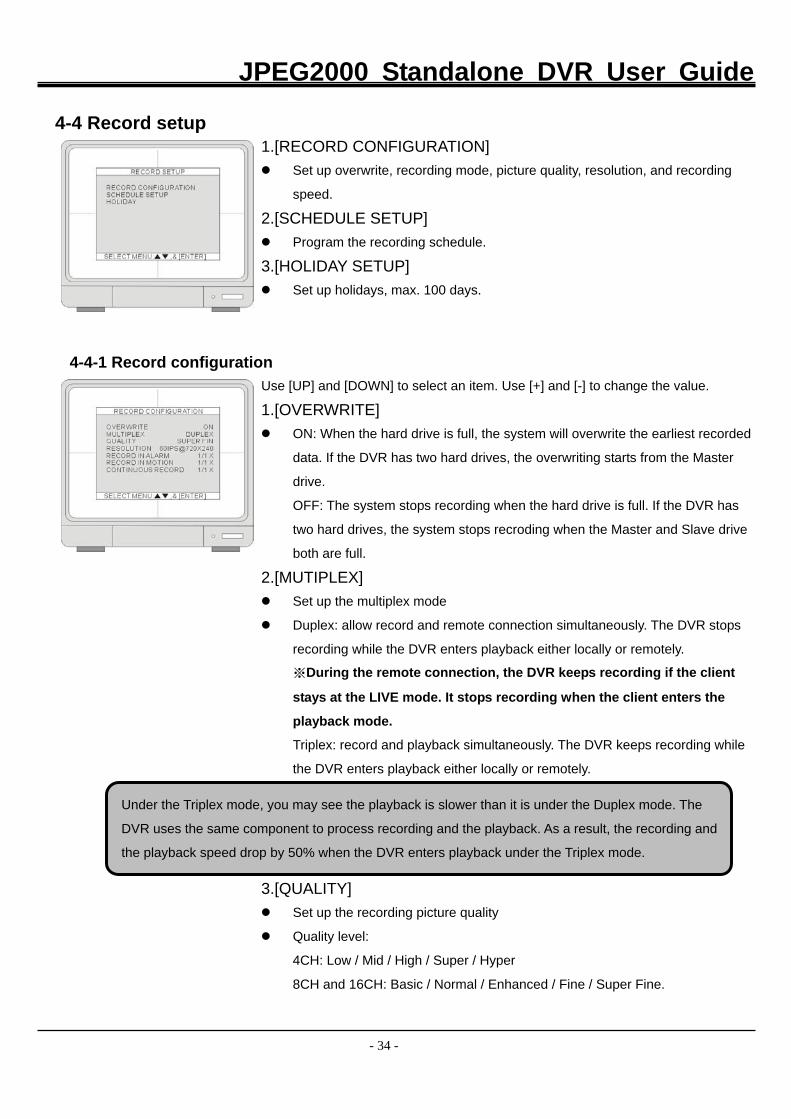
4-4-1 Record configuration
Use [UP] and [DOWN] to select an item. Use [+] and [-] to change the value.
1.[OVERWRITE] ON: When the hard drive is full, the system will overwrite the earliest recorded
data. If the DVR has two hard drives, the overwriting starts from the Master
drive.
OFF: The system stops recording when the hard drive is full. If the DVR has
two hard drives, the system stops recroding when the Master and Slave drive
both are full.
2.[MUTIPLEX] Set up the multiplex mode
Duplex: allow record and remote connection simultaneously. The DVR stops
recording while the DVR enters playback either locally or remotely.
※During the remote connection, the DVR keeps recording if the client
stays at the LIVE mode. It stops recording when the client enters the
playback mode.
Triplex: record and playback simultaneously. The DVR keeps recording while
the DVR enters playback either locally or remotely.
3.[QUALITY] Set up the recording picture quality
Quality level:
4CH: Low / Mid / High / Super / Hyper
8CH and 16CH: Basic / Normal / Enhanced / Fine / Super Fine.
Under the Triplex mode, you may see the playback is slower than it is under the Duplex mode. The
DVR uses the same component to process recording and the playback. As a result, the recording and
the playback speed drop by 50% when the DVR enters playback under the Triplex mode.
JPEG2000 Standalone DVR User Guide
- 35 -
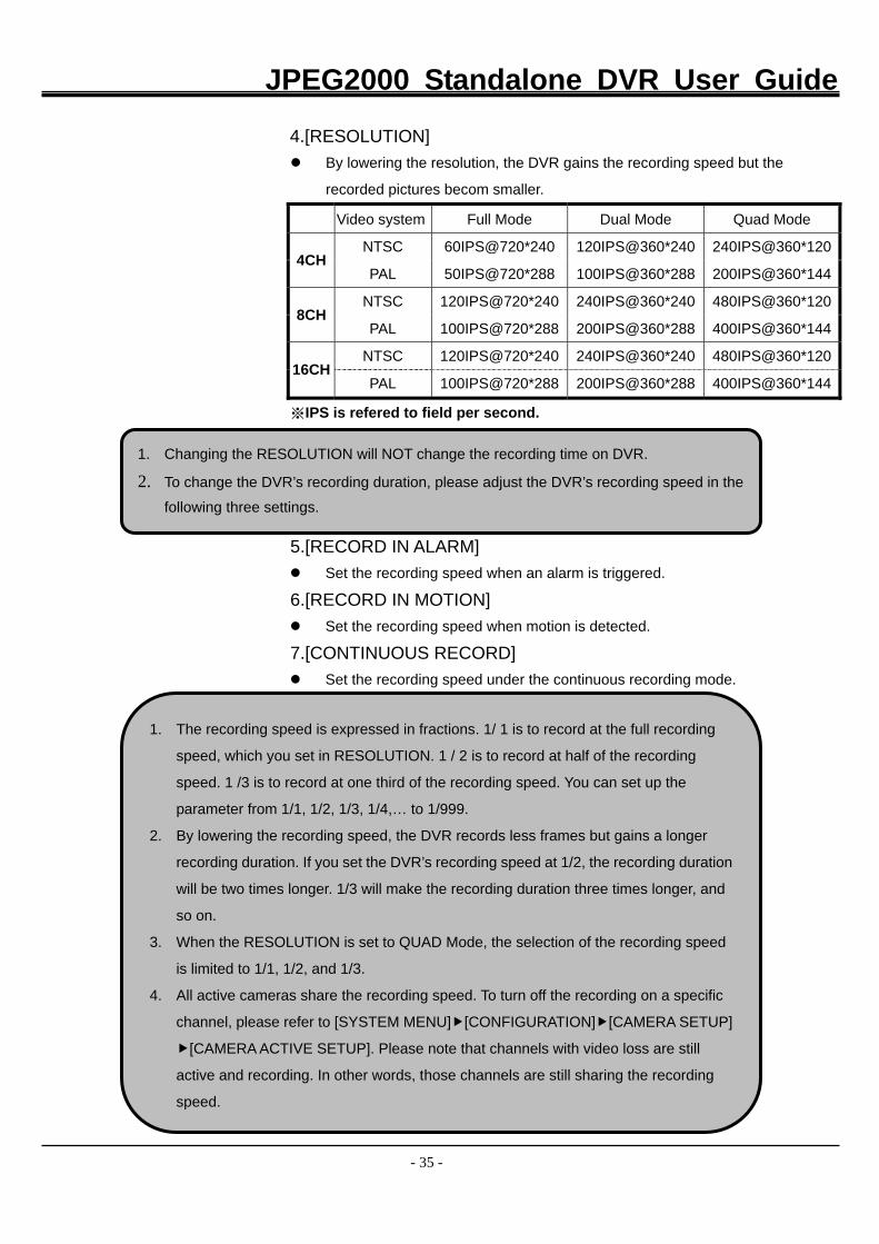
4.[RESOLUTION] By lowering the resolution, the DVR gains the recording speed but the
recorded pictures becom smaller.
Video system Full Mode Dual Mode Quad Mode
NTSC 60IPS@720*240 120IPS@360*240 240IPS@360*1204CH
PAL 50IPS@720*288 100IPS@360*288 200IPS@360*144
NTSC 120IPS@720*240 240IPS@360*240 480IPS@360*1208CH
PAL 100IPS@720*288 200IPS@360*288 400IPS@360*144
NTSC 120IPS@720*240 240IPS@360*240 480IPS@360*12016CH
PAL 100IPS@720*288 200IPS@360*288 400IPS@360*144
※IPS is refered to field per second.
5.[RECORD IN ALARM] Set the recording speed when an alarm is triggered.
6.[RECORD IN MOTION] Set the recording speed when motion is detected.
7.[CONTINUOUS RECORD] Set the recording speed under the continuous recording mode.
1. The recording speed is expressed in fractions. 1/ 1 is to record at the full recording
speed, which you set in RESOLUTION. 1 / 2 is to record at half of the recording
speed. 1 /3 is to record at one third of the recording speed. You can set up the
parameter from 1/1, 1/2, 1/3, 1/4,… to 1/999.
2. By lowering the recording speed, the DVR records less frames but gains a longer
recording duration. If you set the DVR’s recording speed at 1/2, the recording duration
will be two times longer. 1/3 will make the recording duration three times longer, and
so on.
3. When the RESOLUTION is set to QUAD Mode, the selection of the recording speed
is limited to 1/1, 1/2, and 1/3.
4. All active cameras share the recording speed. To turn off the recording on a specific
channel, please refer to [SYSTEM MENU] [CONFIGURATION] [CAMERA SETUP]
[CAMERA ACTIVE SETUP]. Please note that channels with video loss are still
active and recording. In other words, those channels are still sharing the recording
speed.
1. Changing the RESOLUTION will NOT change the recording time on DVR.
2. To change the DVR’s recording duration, please adjust the DVR’s recording speed in the
following three settings.
JPEG2000 Standalone DVR User Guide
- 36 -
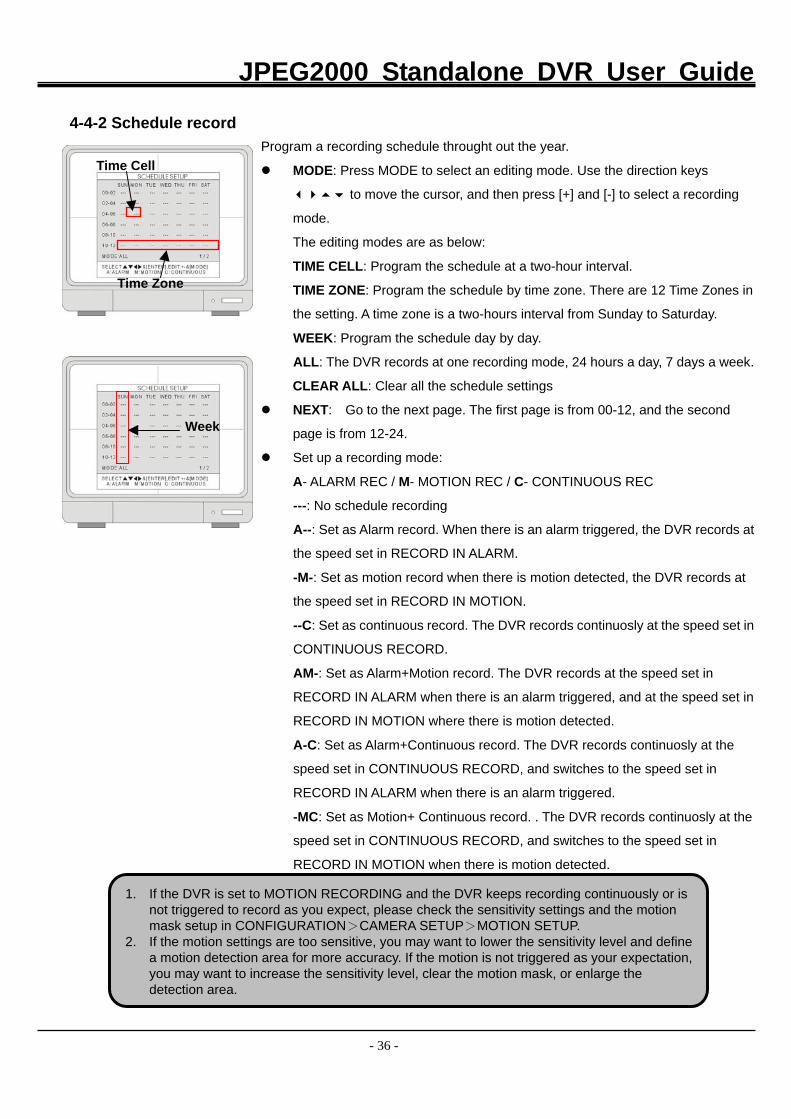
4-4-2 Schedule record
Program a recording schedule throught out the year.
MODE: Press MODE to select an editing mode. Use the direction keys
to move the cursor, and then press [+] and [-] to select a recording
mode.
The editing modes are as below:
TIME CELL: Program the schedule at a two-hour interval.
TIME ZONE: Program the schedule by time zone. There are 12 Time Zones in
the setting. A time zone is a two-hours interval from Sunday to Saturday.
WEEK: Program the schedule day by day.
ALL: The DVR records at one recording mode, 24 hours a day, 7 days a week.
CLEAR ALL: Clear all the schedule settings
NEXT: Go to the next page. The first page is from 00-12, and the second
page is from 12-24.
Set up a recording mode:
A- ALARM REC / M- MOTION REC / C- CONTINUOUS REC
---: No schedule recording
A--: Set as Alarm record. When there is an alarm triggered, the DVR records at
the speed set in RECORD IN ALARM.
-M-: Set as motion record when there is motion detected, the DVR records at
the speed set in RECORD IN MOTION.
--C: Set as continuous record. The DVR records continuosly at the speed set in
CONTINUOUS RECORD.
AM-: Set as Alarm+Motion record. The DVR records at the speed set in
RECORD IN ALARM when there is an alarm triggered, and at the speed set in
RECORD IN MOTION where there is motion detected.
A-C: Set as Alarm+Continuous record. The DVR records continuosly at the
speed set in CONTINUOUS RECORD, and switches to the speed set in
RECORD IN ALARM when there is an alarm triggered.
-MC: Set as Motion+ Continuous record. . The DVR records continuosly at the
speed set in CONTINUOUS RECORD, and switches to the speed set in
RECORD IN MOTION when there is motion detected.
Time Cell
Time Zone
Week
1. If the DVR is set to MOTION RECORDING and the DVR keeps recording continuously or is not triggered to record as you expect, please check the sensitivity settings and the motion mask setup in CONFIGURATION>CAMERA SETUP>MOTION SETUP.
2. If the motion settings are too sensitive, you may want to lower the sensitivity level and definea motion detection area for more accuracy. If the motion is not triggered as your expectation,you may want to increase the sensitivity level, clear the motion mask, or enlarge the detection area.
JPEG2000 Standalone DVR User Guide
- 37 -
4-4-3 Holiday setup
Set up the holidays through out the year. You can program up to 100 days as
holidays. The recording schedule of the holidays is the same as the settings of
Sunday.
Press MODE and set the editing mode as EDIT HOLIDAY. Use direction key
to select and press ENTER to mark the day as a holiday.
To clear the settings, press MODE to set the editing mode to CLEAR ALL DATA
or CLEAR MON DATA (clear data month by month). Press ENTER to clear the
settings.
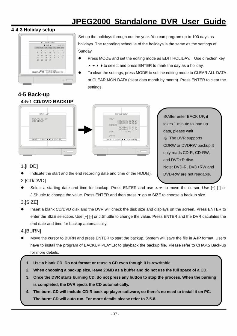
4-5 Back-up 4-5-1 CD/DVD BACKUP
1.[HDD] Indicate the start and the end recording date and time of the HDD(s).
2.[CD/DVD] Select a starting date and time for backup. Press ENTER and use to move the cursor. Use [+] [-] or
J.Shuttle to change the value. Press ENTER and then press go to SIZE to choose a backup size.
3.[SIZE] Insert a blank CD/DVD disk and the DVR will check the disk size and displays on the screen. Press ENTER to
enter the SIZE selection. Use [+] [-] or J.Shuttle to change the value. Press ENTER and the DVR caculates the
end date and time for backup automatically.
4.[BURN] Move the cursor to BURN and press ENTER to start the backup. System will save the file in AJP format. Users
have to install the program of BACKUP PLAYER to playback the backup file. Please refer to CHAP.5 Back-up
for more details.
1. Use a blank CD. Do not format or reuse a CD even though it is rewritable.
2. When choosing a backup size, leave 20MB as a buffer and do not use the full space of a CD.
3. Once the DVR starts burning CD, do not press any button to stop the process. When the burning
is completed, the DVR ejects the CD automatically.
4. The burnt CD will include CD-R back up player software, so there’s no need to install it on PC.
The burnt CD will auto run. For more details please refer to 7-5-8.
※After enter BACK UP, it
takes 1 minute to load up
data, please wait.
※ The DVR supports
CDRW or DVDRW backup.It
only reads CD-R, CD-RW,
and DVD+R disc
Note: DVD-R, DVD+RW and
DVD-RW are not readable.
JPEG2000 Standalone DVR User Guide
- 38 -
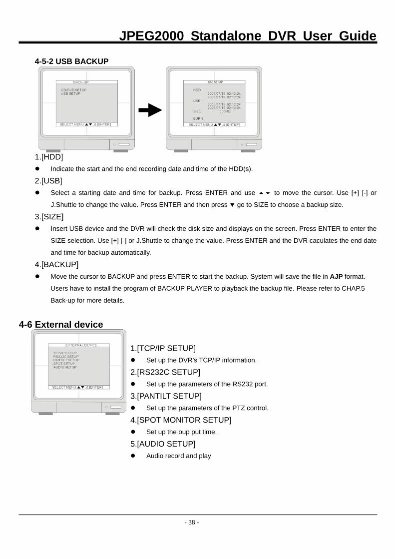
4-5-2 USB BACKUP
1.[HDD] Indicate the start and the end recording date and time of the HDD(s).
2.[USB] Select a starting date and time for backup. Press ENTER and use to move the cursor. Use [+] [-] or
J.Shuttle to change the value. Press ENTER and then press go to SIZE to choose a backup size.
3.[SIZE] Insert USB device and the DVR will check the disk size and displays on the screen. Press ENTER to enter the
SIZE selection. Use [+] [-] or J.Shuttle to change the value. Press ENTER and the DVR caculates the end date
and time for backup automatically.
4.[BACKUP] Move the cursor to BACKUP and press ENTER to start the backup. System will save the file in AJP format.
Users have to install the program of BACKUP PLAYER to playback the backup file. Please refer to CHAP.5
Back-up for more details.
4-6 External device
1.[TCP/IP SETUP] Set up the DVR’s TCP/IP information.
2.[RS232C SETUP] Set up the parameters of the RS232 port.
3.[PANTILT SETUP] Set up the parameters of the PTZ control.
4.[SPOT MONITOR SETUP] Set up the oup put time.
5.[AUDIO SETUP] Audio record and play
JPEG2000 Standalone DVR User Guide
- 39 -
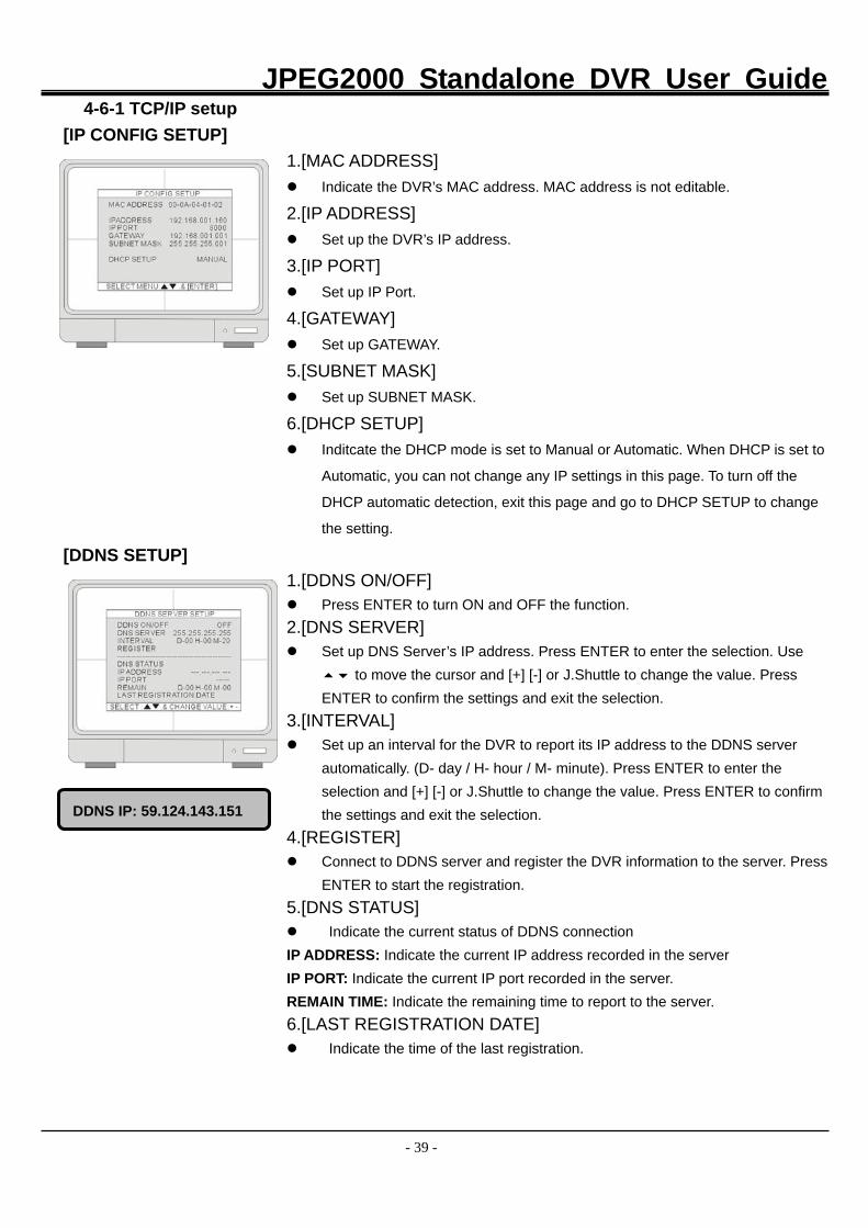
4-6-1 TCP/IP setup
[IP CONFIG SETUP] 1.[MAC ADDRESS]
Indicate the DVR’s MAC address. MAC address is not editable.
2.[IP ADDRESS] Set up the DVR’s IP address.
3.[IP PORT] Set up IP Port.
4.[GATEWAY] Set up GATEWAY.
5.[SUBNET MASK] Set up SUBNET MASK.
6.[DHCP SETUP] Inditcate the DHCP mode is set to Manual or Automatic. When DHCP is set to
Automatic, you can not change any IP settings in this page. To turn off the
DHCP automatic detection, exit this page and go to DHCP SETUP to change
the setting.
[DDNS SETUP] 1.[DDNS ON/OFF]
Press ENTER to turn ON and OFF the function. 2.[DNS SERVER]
Set up DNS Server’s IP address. Press ENTER to enter the selection. Use to move the cursor and [+] [-] or J.Shuttle to change the value. Press
ENTER to confirm the settings and exit the selection. 3.[INTERVAL]
Set up an interval for the DVR to report its IP address to the DDNS server automatically. (D- day / H- hour / M- minute). Press ENTER to enter the selection and [+] [-] or J.Shuttle to change the value. Press ENTER to confirm the settings and exit the selection.
4.[REGISTER] Connect to DDNS server and register the DVR information to the server. Press
ENTER to start the registration. 5.[DNS STATUS] Indicate the current status of DDNS connection
IP ADDRESS: Indicate the current IP address recorded in the server IP PORT: Indicate the current IP port recorded in the server.
REMAIN TIME: Indicate the remaining time to report to the server. 6.[LAST REGISTRATION DATE]
Indicate the time of the last registration.
DDNS IP: 59.124.143.151
JPEG2000 Standalone DVR User Guide
- 40 -
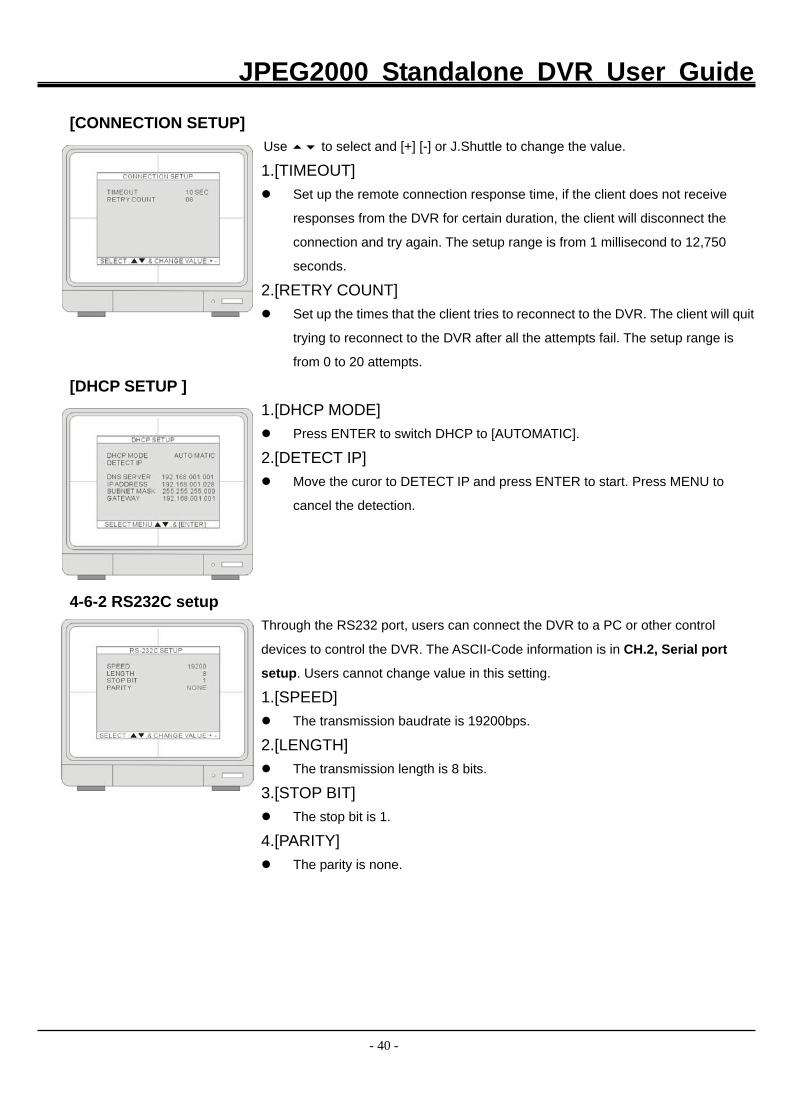
[CONNECTION SETUP] Use to select and [+] [-] or J.Shuttle to change the value.
1.[TIMEOUT] Set up the remote connection response time, if the client does not receive
responses from the DVR for certain duration, the client will disconnect the
connection and try again. The setup range is from 1 millisecond to 12,750
seconds.
2.[RETRY COUNT] Set up the times that the client tries to reconnect to the DVR. The client will quit
trying to reconnect to the DVR after all the attempts fail. The setup range is
from 0 to 20 attempts.
[DHCP SETUP ] 1.[DHCP MODE] Press ENTER to switch DHCP to [AUTOMATIC].
2.[DETECT IP] Move the curor to DETECT IP and press ENTER to start. Press MENU to
cancel the detection.
4-6-2 RS232C setup Through the RS232 port, users can connect the DVR to a PC or other control
devices to control the DVR. The ASCII-Code information is in CH.2, Serial port
setup. Users cannot change value in this setting.
1.[SPEED] The transmission baudrate is 19200bps.
2.[LENGTH] The transmission length is 8 bits.
3.[STOP BIT] The stop bit is 1.
4.[PARITY] The parity is none.
JPEG2000 Standalone DVR User Guide
- 41 -
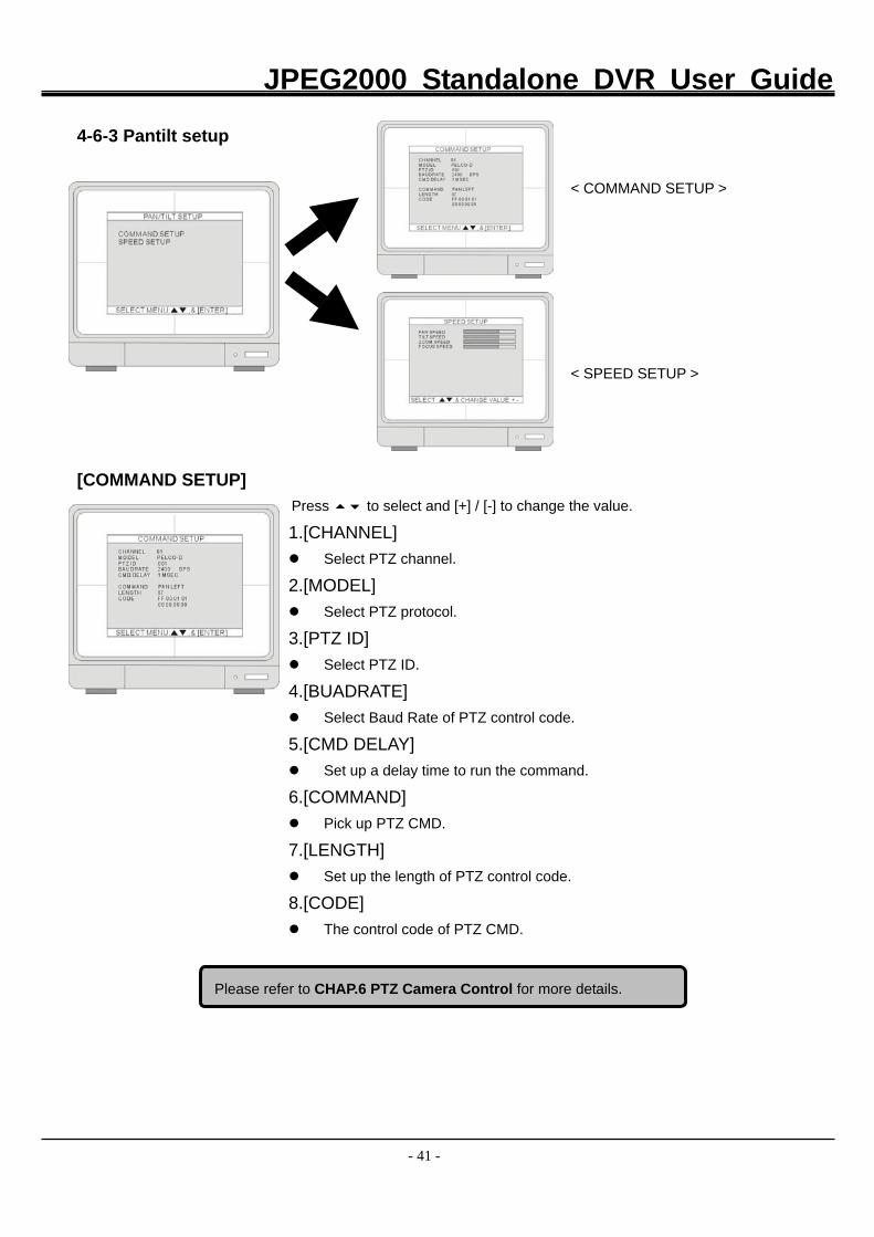
4-6-3 Pantilt setup < COMMAND SETUP >
< SPEED SETUP >
[COMMAND SETUP]
Press to select and [+] / [-] to change the value.
1.[CHANNEL] Select PTZ channel.
2.[MODEL] Select PTZ protocol.
3.[PTZ ID] Select PTZ ID.
4.[BUADRATE] Select Baud Rate of PTZ control code.
5.[CMD DELAY] Set up a delay time to run the command.
6.[COMMAND] Pick up PTZ CMD.
7.[LENGTH] Set up the length of PTZ control code.
8.[CODE] The control code of PTZ CMD.
Please refer to CHAP.6 PTZ Camera Control for more details.
JPEG2000 Standalone DVR User Guide
- 42 -
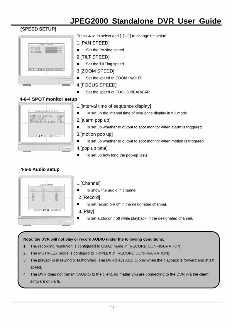
[SPEED SETUP] Press to select and [+] / [-] to change the value. 1.[PAN SPEED] Set the PANing speed.
2.[TILT SPEED] Set the TILTing speed.
3.[ZOOM SPEED] Set the speed of ZOOM IN/OUT.
4.[FOCUS SPEED] Set the speed of FOCUS NEAR/FAR.
4-6-4 SPOT monitor setup 1.[interval time of sequence display] To set up the interval time of sequence display in full mode
2.[alarm pop up] To set up whether to output to spot monitor when alarm is triggered.
3.[motion pop up] To set up whether to output to spot monitor when motion is triggered.
4.[pop up time] To set up how long the pop-up lasts.
4-6-5 Audio setup 1.[Channel]
To show the audio in channel.
2.[Record] To set record on/ off in the designated channel.
3.[Play] To set audio on / off while playback in the designated channel.
Note: the DVR will not play or record AUDIO under the following conditions:
1. The recording resolution is configured to QUAD mode in [RECORD CONFIGURATION].
2. The MUTIPLEX mode is configurd to TRIPLEX in [RECORD CONFIGURATION].
3. The playack is in rewind or fastforward. The DVR plays AUDIO only when the playback is forward and at 1X
speed.
4. The DVR does not transmit AUDIO to the client, no matter you are connecting to the DVR viia the client
software or via IE.
JPEG2000 Standalone DVR User Guide
- 43 -
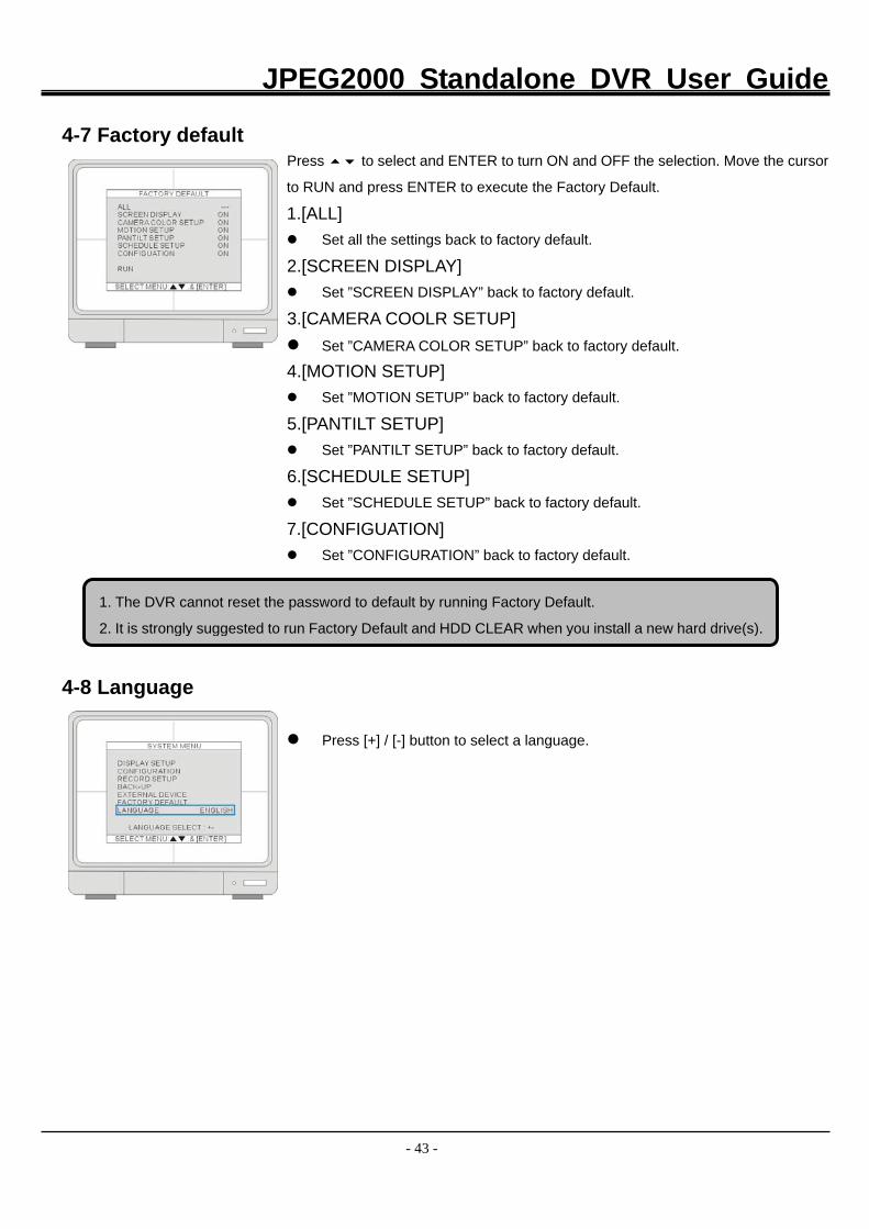
4-7 Factory default
Press to select and ENTER to turn ON and OFF the selection. Move the cursor
to RUN and press ENTER to execute the Factory Default.
1.[ALL] Set all the settings back to factory default.
2.[SCREEN DISPLAY] Set ”SCREEN DISPLAY” back to factory default.
3.[CAMERA COOLR SETUP] Set ”CAMERA COLOR SETUP” back to factory default.
4.[MOTION SETUP] Set ”MOTION SETUP” back to factory default.
5.[PANTILT SETUP] Set ”PANTILT SETUP” back to factory default.
6.[SCHEDULE SETUP] Set ”SCHEDULE SETUP” back to factory default.
7.[CONFIGUATION] Set ”CONFIGURATION” back to factory default.
4-8 Language
Press [+] / [-] button to select a language.
1. The DVR cannot reset the password to default by running Factory Default.
2. It is strongly suggested to run Factory Default and HDD CLEAR when you install a new hard drive(s).
JPEG2000 Standalone DVR User Guide
- 44 -
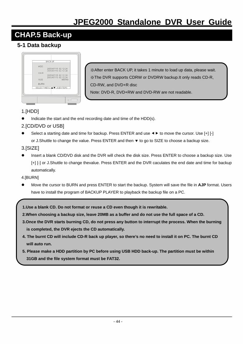
5-1 Data backup
1.[HDD] Indicate the start and the end recording date and time of the HDD(s).
2.[CD/DVD or USB] Select a starting date and time for backup. Press ENTER and use to move the cursor. Use [+] [-]
or J.Shuttle to change the value. Press ENTER and then to go to SIZE to choose a backup size.
3.[SIZE] Insert a blank CD/DVD disk and the DVR will check the disk size. Press ENTER to choose a backup size. Use
[+] [-] or J.Shuttle to change thevalue. Press ENTER and the DVR caculates the end date and time for backup
automatically.
4.[BURN]
Move the cursor to BURN and press ENTER to start the backup. System will save the file in AJP format. Users
have to install the program of BACKUP PLAYER to playback the backup file on a PC.
CHAP.5 Back-up
※After enter BACK UP, it takes 1 minute to load up data, please wait.
※The DVR supports CDRW or DVDRW backup.It only reads CD-R,
CD-RW, and DVD+R disc
Note: DVD-R, DVD+RW and DVD-RW are not readable.
1.Use a blank CD. Do not format or reuse a CD even though it is rewritable.
2.When choosing a backup size, leave 20MB as a buffer and do not use the full space of a CD.
3.Once the DVR starts burning CD, do not press any button to interrupt the process. When the burning
is completed, the DVR ejects the CD automatically.
4. The burnt CD will include CD-R back up player, so there’s no need to install it on PC. The burnt CD
will auto run.
5. Please make a HDD partition by PC before using USB HDD back-up. The partition must be within
31GB and the file system format must be FAT32.
JPEG2000 Standalone DVR User Guide
- 45 -
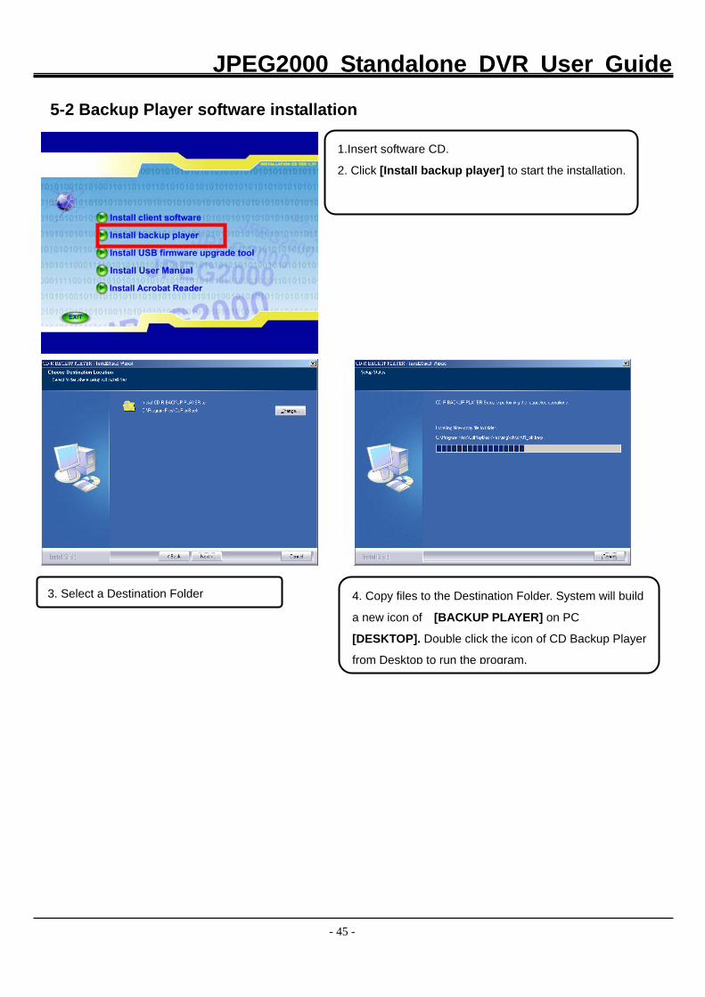
5-2 Backup Player software installation
1.Insert software CD.
2. Click [Install backup player] to start the installation.
3. Select a Destination Folder 4. Copy files to the Destination Folder. System will build
a new icon of [BACKUP PLAYER] on PC
[DESKTOP]. Double click the icon of CD Backup Player
from Desktop to run the program.
JPEG2000 Standalone DVR User Guide
- 46 -
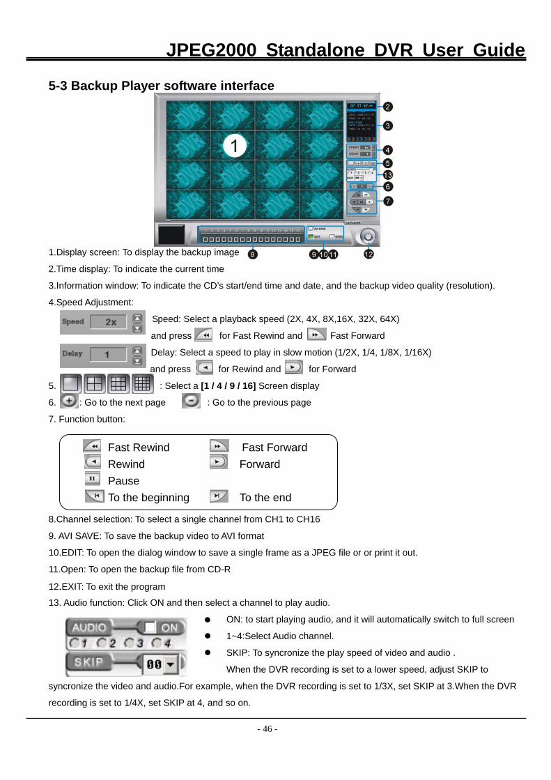
5-3 Backup Player software interface
1.Display screen: To display the backup image 2.Time display: To indicate the current time 3.Information window: To indicate the CD’s start/end time and date, and the backup video quality (resolution).
4.Speed Adjustment: Speed: Select a playback speed (2X, 4X, 8X,16X, 32X, 64X)
and press for Fast Rewind and Fast Forward
Delay: Select a speed to play in slow motion (1/2X, 1/4, 1/8X, 1/16X)
and press for Rewind and for Forward
5. : Select a [1 / 4 / 9 / 16] Screen display
6. : Go to the next page : Go to the previous page
7. Function button:
8.Channel selection: To select a single channel from CH1 to CH16
9. AVI SAVE: To save the backup video to AVI format
10.EDIT: To open the dialog window to save a single frame as a JPEG file or or print it out.
11.Open: To open the backup file from CD-R
12.EXIT: To exit the program 13. Audio function: Click ON and then select a channel to play audio.
ON: to start playing audio, and it will automatically switch to full screen
1~4:Select Audio channel.
SKIP: To syncronize the play speed of video and audio .
When the DVR recording is set to a lower speed, adjust SKIP to
syncronize the video and audio.For example, when the DVR recording is set to 1/3X, set SKIP at 3.When the DVR
recording is set to 1/4X, set SKIP at 4, and so on.
Fast Rewind Fast Forward Rewind ForwardPause To the beginning To the end
JPEG2000 Standalone DVR User Guide
- 47 -
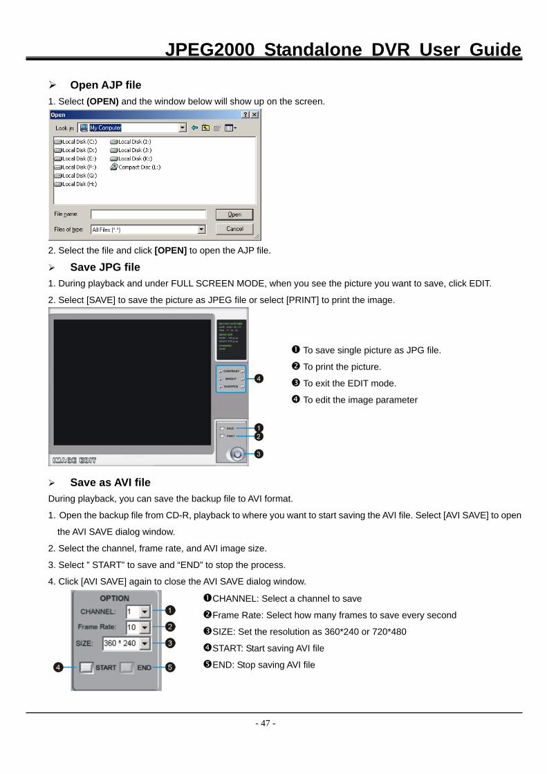
Open AJP file 1. Select (OPEN) and the window below will show up on the screen.
2. Select the file and click [OPEN] to open the AJP file.
Save JPG file
1. During playback and under FULL SCREEN MODE, when you see the picture you want to save, click EDIT.
2. Select [SAVE] to save the picture as JPEG file or select [PRINT] to print the image.
To save single picture as JPG file.
To print the picture.
To exit the EDIT mode.
To edit the image parameter
Save as AVI file During playback, you can save the backup file to AVI format.
1. Open the backup file from CD-R, playback to where you want to start saving the AVI file. Select [AVI SAVE] to open
the AVI SAVE dialog window.
2. Select the channel, frame rate, and AVI image size.
3. Select ” START” to save and “END” to stop the process.
4. Click [AVI SAVE] again to close the AVI SAVE dialog window.
CHANNEL: Select a channel to save Frame Rate: Select how many frames to save every second
SIZE: Set the resolution as 360*240 or 720*480
START: Start saving AVI file
END: Stop saving AVI file
JPEG2000 Standalone DVR User Guide
- 48 -
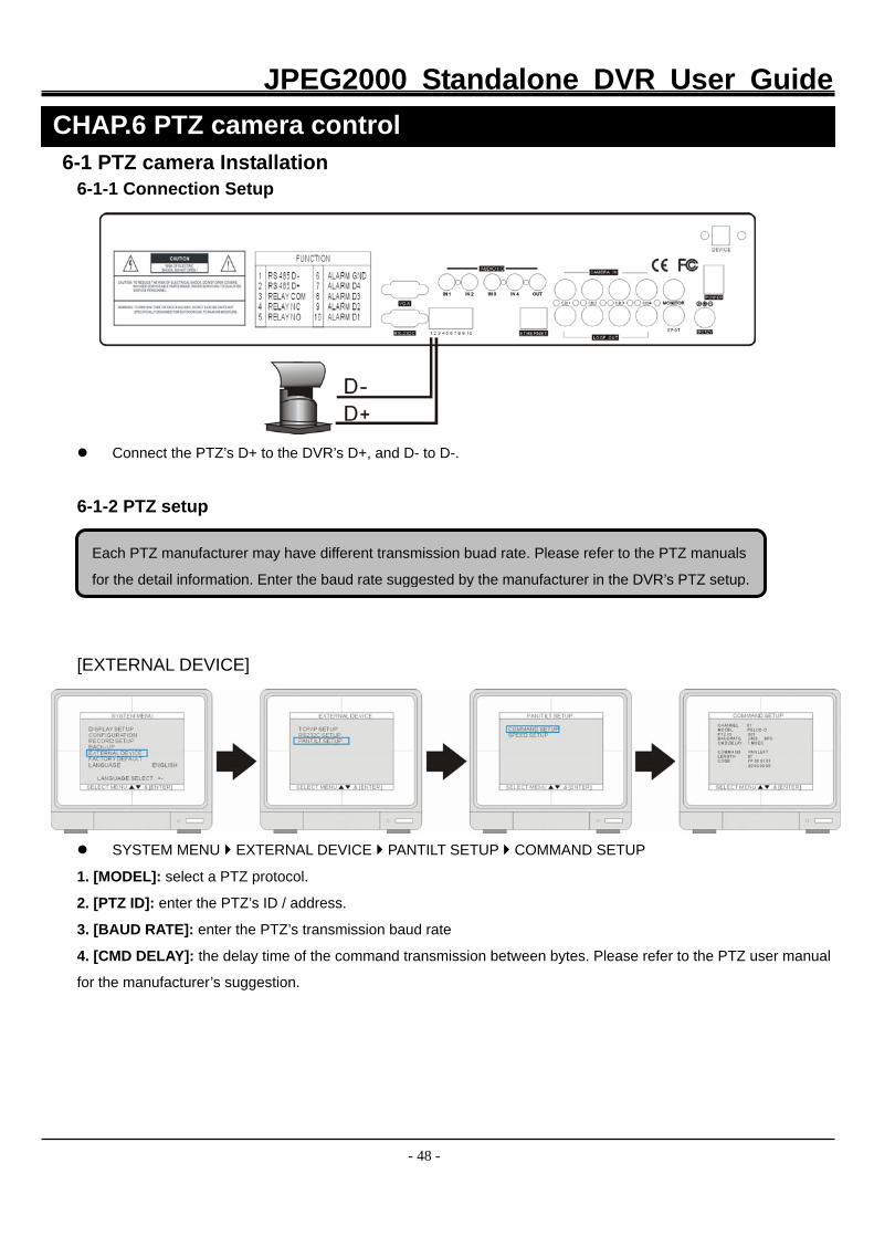
6-1 PTZ camera Installation 6-1-1 Connection Setup
Connect the PTZ’s D+ to the DVR’s D+, and D- to D-.
6-1-2 PTZ setup
[EXTERNAL DEVICE]
SYSTEM MENU EXTERNAL DEVICE PANTILT SETUP COMMAND SETUP
1. [MODEL]: select a PTZ protocol.
2. [PTZ ID]: enter the PTZ’s ID / address.
3. [BAUD RATE]: enter the PTZ’s transmission baud rate
4. [CMD DELAY]: the delay time of the command transmission between bytes. Please refer to the PTZ user manual
for the manufacturer’s suggestion.
CHAP.6 PTZ camera control
Each PTZ manufacturer may have different transmission buad rate. Please refer to the PTZ manuals
for the detail information. Enter the baud rate suggested by the manufacturer in the DVR’s PTZ setup.
JPEG2000 Standalone DVR User Guide
- 49 -
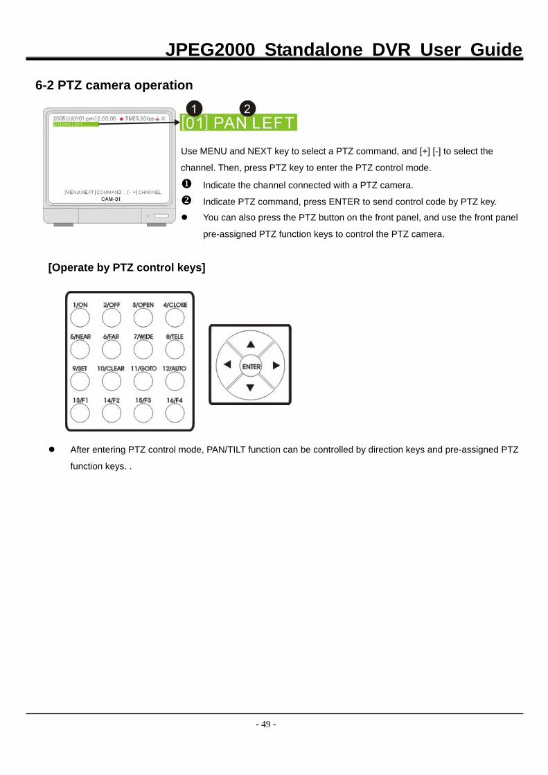
6-2 PTZ camera operation
Use MENU and NEXT key to select a PTZ command, and [+] [-] to select the
channel. Then, press PTZ key to enter the PTZ control mode.
Indicate the channel connected with a PTZ camera. Indicate PTZ command, press ENTER to send control code by PTZ key.
You can also press the PTZ button on the front panel, and use the front panel
pre-assigned PTZ function keys to control the PTZ camera.
[Operate by PTZ control keys]
After entering PTZ control mode, PAN/TILT function can be controlled by direction keys and pre-assigned PTZ
function keys. .
JPEG2000 Standalone DVR User Guide
- 50 -
7-1 Network Introduction Users have to indentify what kind of Internet access they have before they set up the DVR’s network parameters.
DSL and cable modem are the most popular broadband technologies.
ADSL- Asymmetric Digital Subscriber Line
ADSL is one of xDSL technologies, transmitting digital data over the wires of a local telephone network. Typically,
the download speed of DSL ranges from 128 kilobits per second (kbit/s) to 24,000 kbit/s depending on DSL
technology and service level implemented. Upload speed is lower than download speed. ADSL is the most
popular broadband technology, followed by Cable Modem.
Cable Modem(or Cable)
Cable Modem, Cable Internet Acess, or simply Cable is to deliver the Internet Service over a coaxial cable line,
which can be the cable of your Cable TV. The bandwidth of Cable ranges from 3 Mb to 15 Mb, or more. The
upload bandwidth usually ranges from 384kb to 2Mb, or more. However, the connection speed may drop when
many people are using the sevice at the same time
7-2 Network installation and setup
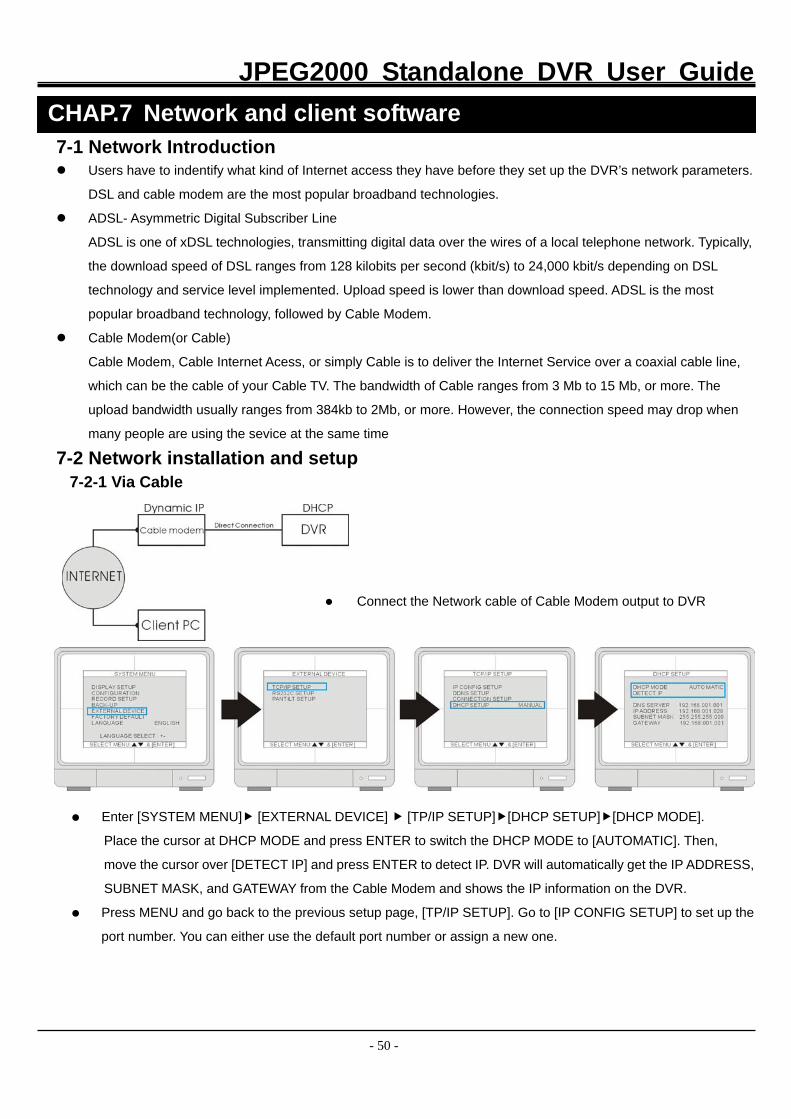
7-2-1 Via Cable
Connect the Network cable of Cable Modem output to DVR
Enter [SYSTEM MENU] [EXTERNAL DEVICE] [TP/IP SETUP] [DHCP SETUP] [DHCP MODE].
Place the cursor at DHCP MODE and press ENTER to switch the DHCP MODE to [AUTOMATIC]. Then,
move the cursor over [DETECT IP] and press ENTER to detect IP. DVR will automatically get the IP ADDRESS,
SUBNET MASK, and GATEWAY from the Cable Modem and shows the IP information on the DVR.
Press MENU and go back to the previous setup page, [TP/IP SETUP]. Go to [IP CONFIG SETUP] to set up the
port number. You can either use the default port number or assign a new one.
CHAP.7 Network and client software
JPEG2000 Standalone DVR User Guide
- 51 -
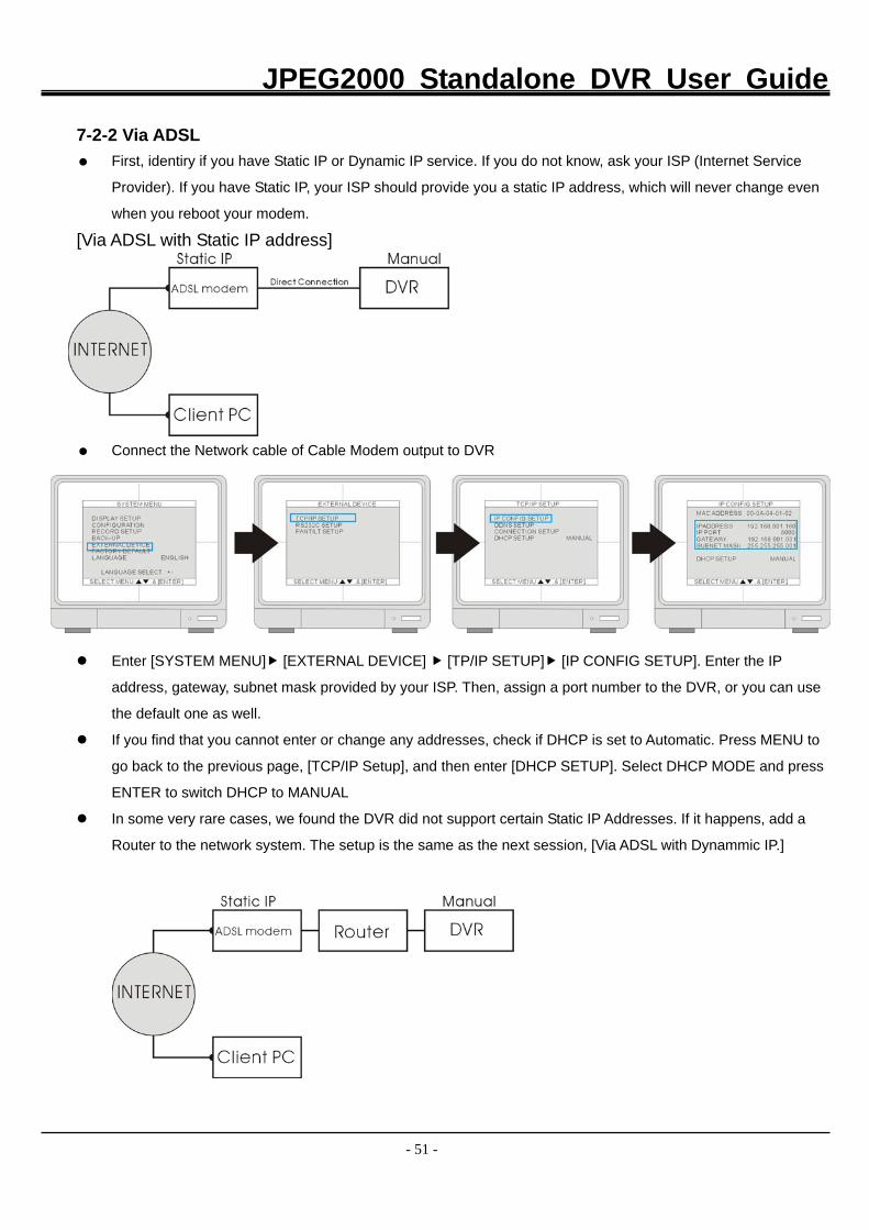
7-2-2 Via ADSL First, identiry if you have Static IP or Dynamic IP service. If you do not know, ask your ISP (Internet Service
Provider). If you have Static IP, your ISP should provide you a static IP address, which will never change even
when you reboot your modem.
[Via ADSL with Static IP address]
Connect the Network cable of Cable Modem output to DVR
Enter [SYSTEM MENU] [EXTERNAL DEVICE] [TP/IP SETUP] [IP CONFIG SETUP]. Enter the IP
address, gateway, subnet mask provided by your ISP. Then, assign a port number to the DVR, or you can use
the default one as well.
If you find that you cannot enter or change any addresses, check if DHCP is set to Automatic. Press MENU to
go back to the previous page, [TCP/IP Setup], and then enter [DHCP SETUP]. Select DHCP MODE and press
ENTER to switch DHCP to MANUAL
In some very rare cases, we found the DVR did not support certain Static IP Addresses. If it happens, add a
Router to the network system. The setup is the same as the next session, [Via ADSL with Dynammic IP.]
JPEG2000 Standalone DVR User Guide
- 52 -
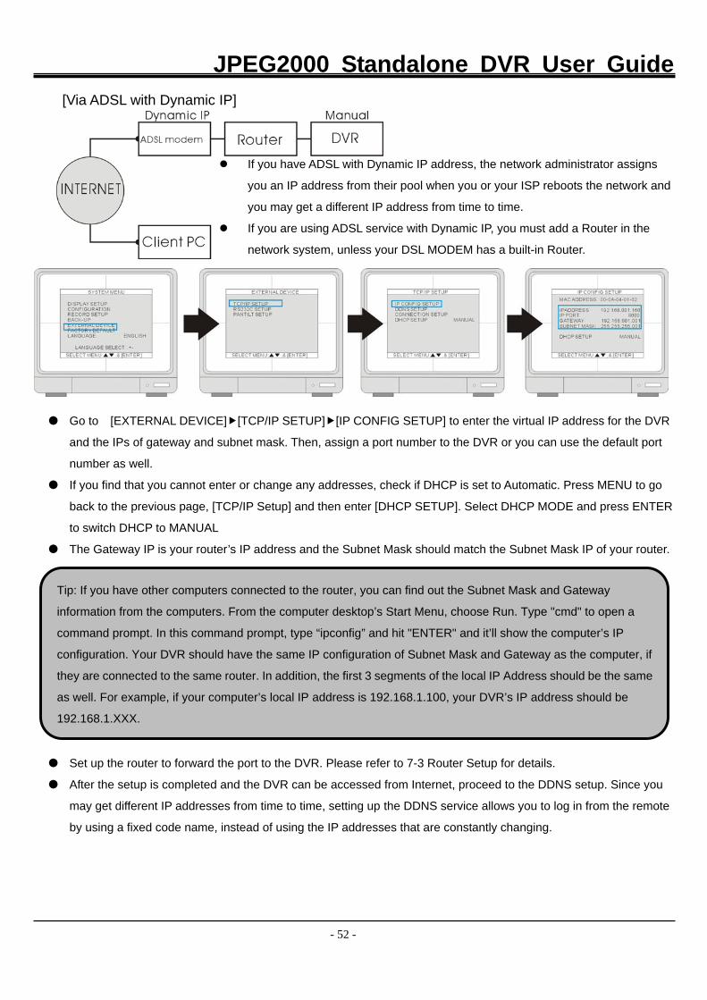
[Via ADSL with Dynamic IP]
If you have ADSL with Dynamic IP address, the network administrator assigns
you an IP address from their pool when you or your ISP reboots the network and
you may get a different IP address from time to time.
If you are using ADSL service with Dynamic IP, you must add a Router in the
network system, unless your DSL MODEM has a built-in Router.
Go to [EXTERNAL DEVICE] [TCP/IP SETUP] [IP CONFIG SETUP] to enter the virtual IP address for the DVR
and the IPs of gateway and subnet mask. Then, assign a port number to the DVR or you can use the default port
number as well.
If you find that you cannot enter or change any addresses, check if DHCP is set to Automatic. Press MENU to go
back to the previous page, [TCP/IP Setup] and then enter [DHCP SETUP]. Select DHCP MODE and press ENTER
to switch DHCP to MANUAL
The Gateway IP is your router’s IP address and the Subnet Mask should match the Subnet Mask IP of your router.
Set up the router to forward the port to the DVR. Please refer to 7-3 Router Setup for details.
After the setup is completed and the DVR can be accessed from Internet, proceed to the DDNS setup. Since you
may get different IP addresses from time to time, setting up the DDNS service allows you to log in from the remote
by using a fixed code name, instead of using the IP addresses that are constantly changing.
Tip: If you have other computers connected to the router, you can find out the Subnet Mask and Gateway
information from the computers. From the computer desktop’s Start Menu, choose Run. Type "cmd" to open a
command prompt. In this command prompt, type “ipconfig” and hit "ENTER" and it’ll show the computer’s IP
configuration. Your DVR should have the same IP configuration of Subnet Mask and Gateway as the computer, if
they are connected to the same router. In addition, the first 3 segments of the local IP Address should be the same
as well. For example, if your computer’s local IP address is 192.168.1.100, your DVR’s IP address should be
192.168.1.XXX.
JPEG2000 Standalone DVR User Guide
- 53 -
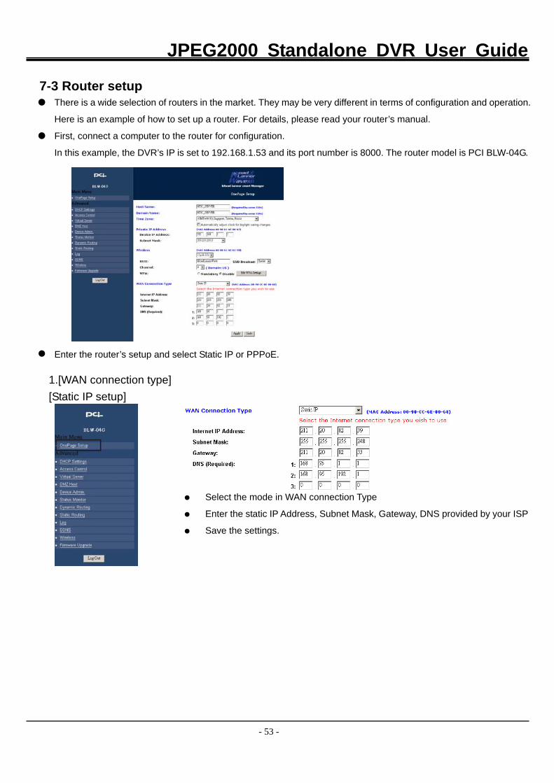
7-3 Router setup There is a wide selection of routers in the market. They may be very different in terms of configuration and operation.
Here is an example of how to set up a router. For details, please read your router’s manual.
First, connect a computer to the router for configuration.
In this example, the DVR’s IP is set to 192.168.1.53 and its port number is 8000. The router model is PCI BLW-04G.
Enter the router’s setup and select Static IP or PPPoE.
1.[WAN connection type]
[Static IP setup]
Select the mode in WAN connection Type
Enter the static IP Address, Subnet Mask, Gateway, DNS provided by your ISP
Save the settings.
JPEG2000 Standalone DVR User Guide
- 54 -
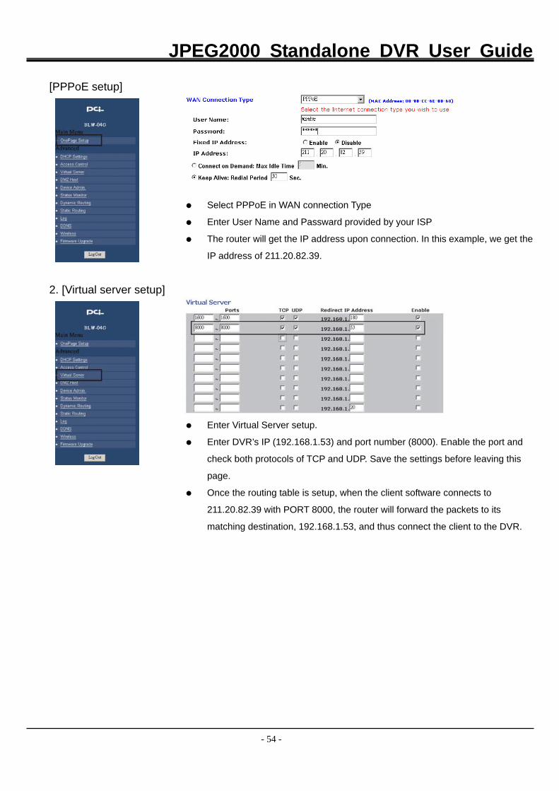
[PPPoE setup]
Select PPPoE in WAN connection Type
Enter User Name and Passward provided by your ISP
The router will get the IP address upon connection. In this example, we get the
IP address of 211.20.82.39. 2. [Virtual server setup]
Enter Virtual Server setup.
Enter DVR’s IP (192.168.1.53) and port number (8000). Enable the port and
check both protocols of TCP and UDP. Save the settings before leaving this
page.
Once the routing table is setup, when the client software connects to
211.20.82.39 with PORT 8000, the router will forward the packets to its
matching destination, 192.168.1.53, and thus connect the client to the DVR.
JPEG2000 Standalone DVR User Guide
- 55 -
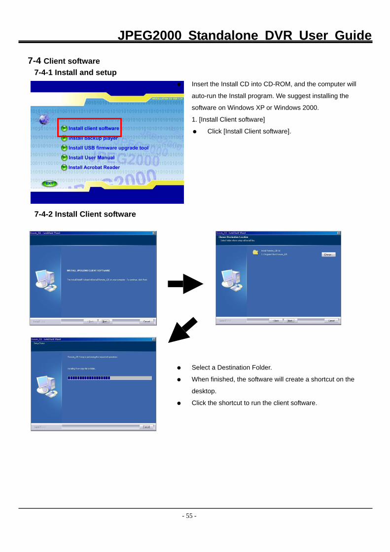
7-4 Client software
7-4-1 Install and setup
Insert the Install CD into CD-ROM, and the computer will
auto-run the Install program. We suggest installing the
software on Windows XP or Windows 2000.
1. [Install Client software]
Click [Install Client software].
7-4-2 Install Client software
Select a Destination Folder.
When finished, the software will create a shortcut on the
desktop.
Click the shortcut to run the client software.
JPEG2000 Standalone DVR User Guide
- 56 -
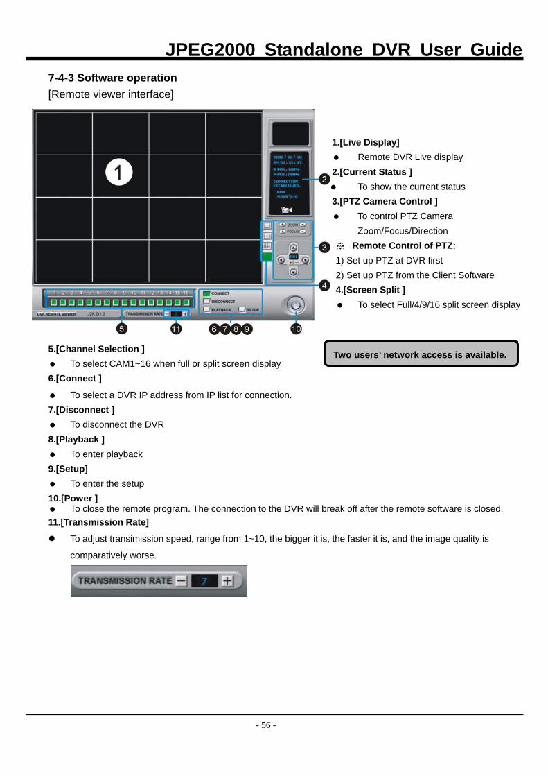
7-4-3 Software operation
[Remote viewer interface]
1.[Live Display]
Remote DVR Live display 2.[Current Status ]
To show the current status 3.[PTZ Camera Control ]
To control PTZ Camera Zoom/Focus/Direction
※ Remote Control of PTZ: 1) Set up PTZ at DVR first 2) Set up PTZ from the Client Software 4.[Screen Split ]
To select Full/4/9/16 split screen display
5.[Channel Selection ] To select CAM1~16 when full or split screen display
6.[Connect ]
To select a DVR IP address from IP list for connection. 7.[Disconnect ]
To disconnect the DVR 8.[Playback ]
To enter playback 9.[Setup]
To enter the setup 10.[Power ]
To close the remote program. The connection to the DVR will break off after the remote software is closed. 11.[Transmission Rate]
To adjust transimission speed, range from 1~10, the bigger it is, the faster it is, and the image quality is
comparatively worse.
Two users’ network access is available.
JPEG2000 Standalone DVR User Guide
- 57 -
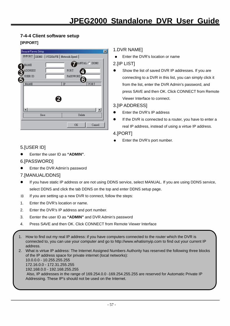
7-4-4 Client software setup
[IP/PORT]
1.DVR NAME] Enter the DVR’s location or name
2.[IP LIST] Show the list of saved DVR IP addresses. If you are
connecting to a DVR in this list, you can simply click it
from the list, enter the DVR Admin’s password, and
press SAVE and then OK. Click CONNECT from Remote
Viewer Interface to connect.
3.[IP ADDRESS] Enter the DVR’s IP address
If the DVR is connected to a router, you have to enter a
real IP address, instead of using a virtue IP address.
4.[PORT] Enter the DVR’s port number.
5.[USER ID] Eenter the user ID as “ADMIN”.
6.[PASSWORD] Enter the DVR Admin’s password
7.[MANUAL/DDNS] If you have static IP address or are not using DDNS service, select MANUAL. If you are using DDNS service,
select DDNS and click the tab DDNS on the top and enter DDNS setup page.
※ If you are setting up a new DVR to connect, follow the steps:
1. Enter the DVR’s location or name.
2. Enter the DVR’s IP address and port number.
3. Eenter the user ID as “ADMIN” and DVR Admin’s password
4. Press SAVE and then OK. Click CONNECT from Remote Viewer Interface
1. How to find out my real IP address: if you have computers connected to the router which the DVR is connected to, you can use your computer and go to http://www.whatismyip.com to find out your current IP address.
2. What is virtue IP address: The Internet Assigned Numbers Authority has reserved the following three blocks of the IP address space for private internet (local networks): 10.0.0.0 - 10.255.255.255 172.16.0.0 - 172.31.255.255 192.168.0.0 - 192.168.255.255 Also, IP addresses in the range of 169.254.0.0 -169.254.255.255 are reserved for Automatic Private IP Addressing. These IP's should not be used on the Internet.
JPEG2000 Standalone DVR User Guide
- 58 -
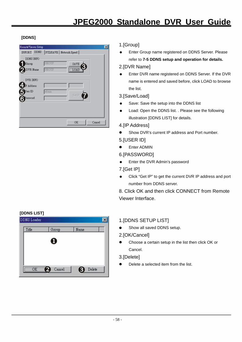
[DDNS]
1.[Group] Enter Group name registered on DDNS Server. Please
refer to 7-5 DDNS setup and operation for details.
2.[DVR Name] Enter DVR name registered on DDNS Server. If the DVR
name is entered and saved before, click LOAD to browse
the list.
3.[Save/Load] Save: Save the setup into the DDNS list
Load: Open the DDNS list. . Please see the following
illustration [DDNS LIST] for details. 4.[IP Address] Show DVR’s current IP address and Port number.
5.[USER ID] Enter ADMIN
6.[PASSWORD] Enter the DVR Admin’s password
7.[Get IP] Click “Get IP” to get the current DVR IP address and port
number from DDNS server.
8. Click OK and then click CONNECT from Remote Viewer Interface.
[DDNS LIST]
1.[DDNS SETUP LIST] Show all saved DDNS setup.
2.[OK/Cancel] Choose a certain setup in the list then click OK or
Cancel.
3.[Delete] Delete a selected item from the list.
JPEG2000 Standalone DVR User Guide
- 59 -
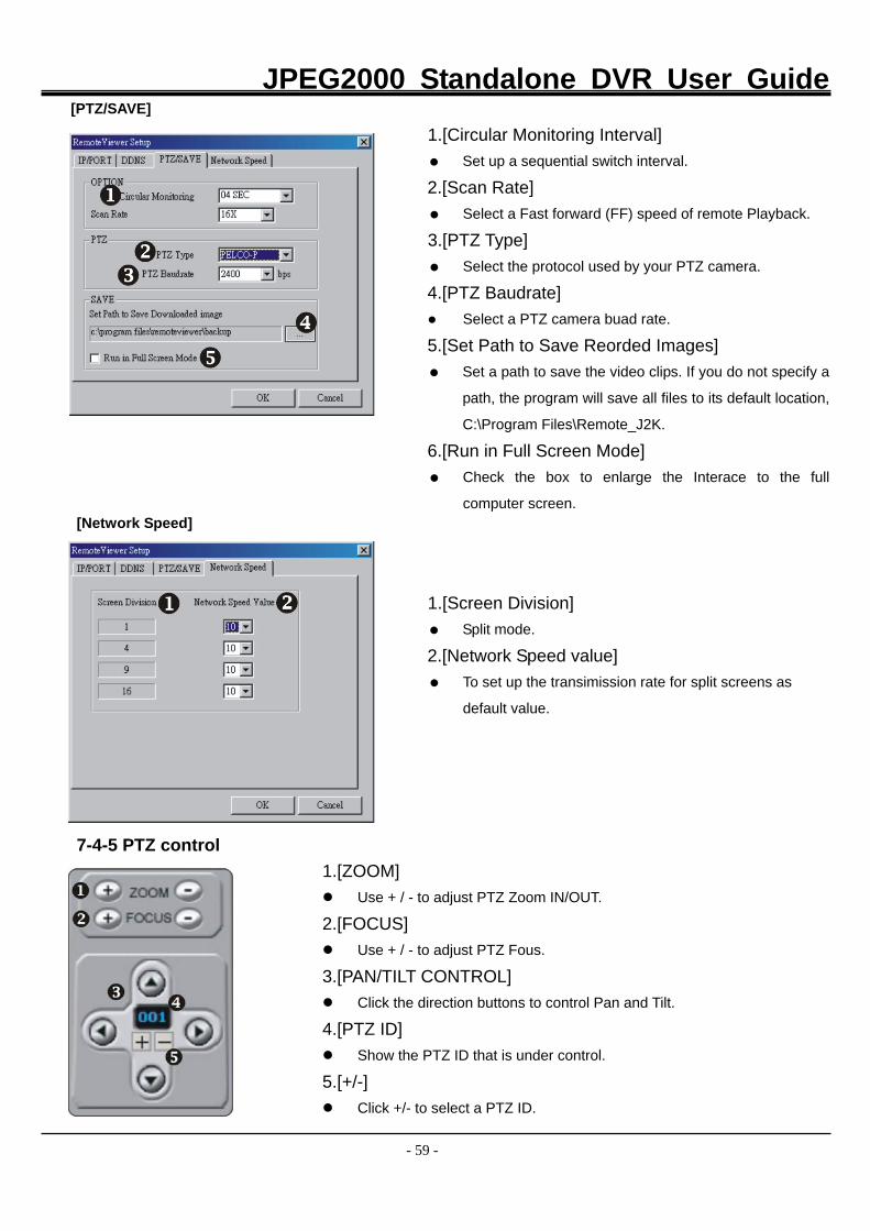
[PTZ/SAVE]
1.[Circular Monitoring Interval] Set up a sequential switch interval.
2.[Scan Rate] Select a Fast forward (FF) speed of remote Playback.
3.[PTZ Type] Select the protocol used by your PTZ camera.
4.[PTZ Baudrate] Select a PTZ camera buad rate.
5.[Set Path to Save Reorded Images] Set a path to save the video clips. If you do not specify a
path, the program will save all files to its default location,
C:\Program Files\Remote_J2K.
6.[Run in Full Screen Mode] Check the box to enlarge the Interace to the full
computer screen. [Network Speed]
1.[Screen Division] Split mode.
2.[Network Speed value] To set up the transimission rate for split screens as
default value.
7-4-5 PTZ control 1.[ZOOM]
Use + / - to adjust PTZ Zoom IN/OUT.
2.[FOCUS] Use + / - to adjust PTZ Fous.
3.[PAN/TILT CONTROL] Click the direction buttons to control Pan and Tilt.
4.[PTZ ID] Show the PTZ ID that is under control.
5.[+/-] Click +/- to select a PTZ ID.
JPEG2000 Standalone DVR User Guide
- 60 -
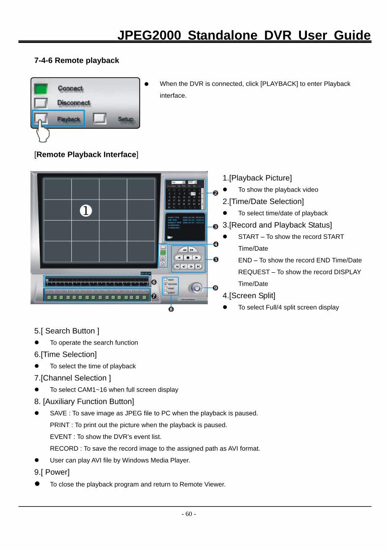
7-4-6 Remote playback
When the DVR is connected, click [PLAYBACK] to enter Playback
interface.
[Remote Playback Interface]
1.[Playback Picture] To show the playback video
2.[Time/Date Selection] To select time/date of playback
3.[Record and Playback Status] START – To show the record START
Time/Date
END – To show the record END Time/Date
REQUEST – To show the record DISPLAY
Time/Date
4.[Screen Split]
To select Full/4 split screen display
5.[ Search Button ] To operate the search function
6.[Time Selection] To select the time of playback
7.[Channel Selection ] To select CAM1~16 when full screen display
8. [Auxiliary Function Button] SAVE : To save image as JPEG file to PC when the playback is paused.
PRINT : To print out the picture when the playback is paused.
EVENT : To show the DVR’s event list.
RECORD : To save the record image to the assigned path as AVI format.
User can play AVI file by Windows Media Player.
9.[ Power] To close the playback program and return to Remote Viewer.
JPEG2000 Standalone DVR User Guide
- 61 -
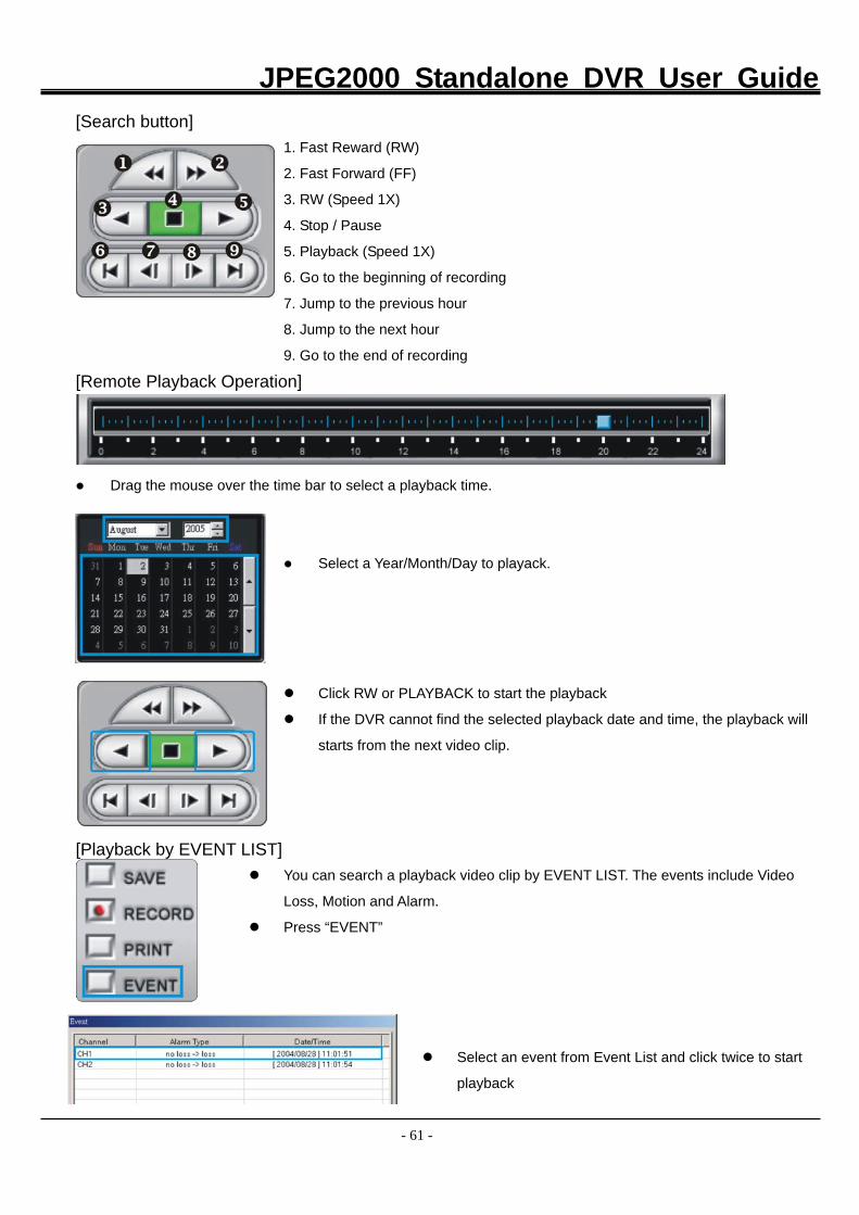
[Search button]
1. Fast Reward (RW)
2. Fast Forward (FF)
3. RW (Speed 1X)
4. Stop / Pause
5. Playback (Speed 1X)
6. Go to the beginning of recording
7. Jump to the previous hour
8. Jump to the next hour
9. Go to the end of recording
[Remote Playback Operation]
Drag the mouse over the time bar to select a playback time.
Select a Year/Month/Day to playack.
Click RW or PLAYBACK to start the playback
If the DVR cannot find the selected playback date and time, the playback will
starts from the next video clip.
[Playback by EVENT LIST] You can search a playback video clip by EVENT LIST. The events include Video
Loss, Motion and Alarm.
Press “EVENT”
Select an event from Event List and click twice to start
playback
JPEG2000 Standalone DVR User Guide
- 62 -
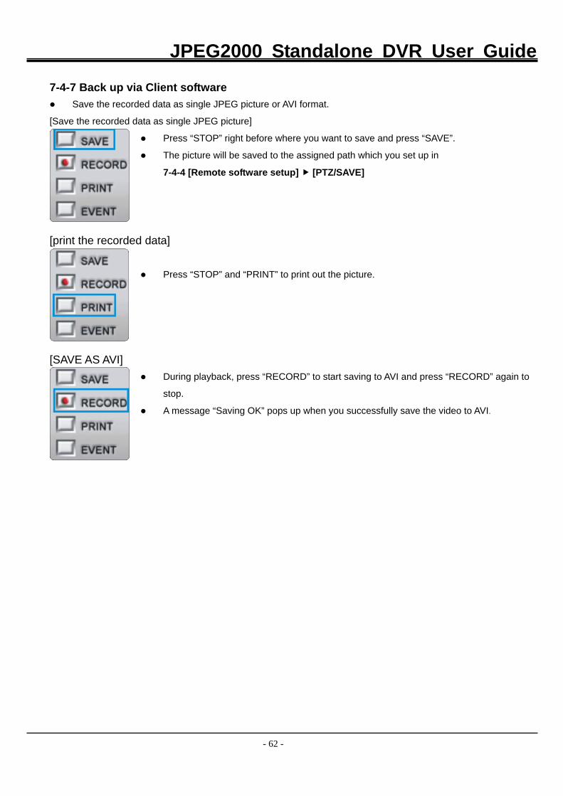
7-4-7 Back up via Client software
Save the recorded data as single JPEG picture or AVI format.
[Save the recorded data as single JPEG picture]
Press “STOP” right before where you want to save and press “SAVE”.
The picture will be saved to the assigned path which you set up in
7-4-4 [Remote software setup] [PTZ/SAVE]
[print the recorded data]
Press “STOP” and “PRINT” to print out the picture.
[SAVE AS AVI] During playback, press “RECORD” to start saving to AVI and press “RECORD” again to
stop.
A message “Saving OK” pops up when you successfully save the video to AVI.
JPEG2000 Standalone DVR User Guide
- 63 -
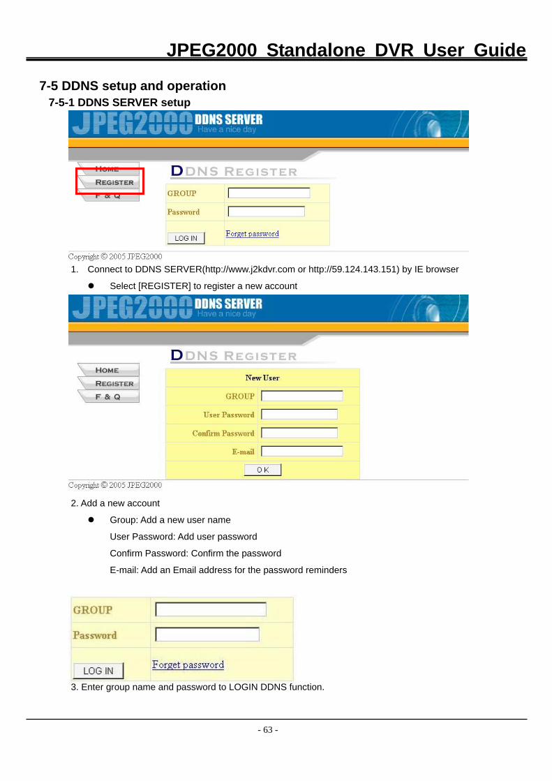
7-5 DDNS setup and operation
7-5-1 DDNS SERVER setup
1. Connect to DDNS SERVER(http://www.j2kdvr.com or http://59.124.143.151) by IE browser
Select [REGISTER] to register a new account
2. Add a new account
Group: Add a new user name
User Password: Add user password
Confirm Password: Confirm the password
E-mail: Add an Email address for the password reminders
3. Enter group name and password to LOGIN DDNS function.
JPEG2000 Standalone DVR User Guide
- 64 -
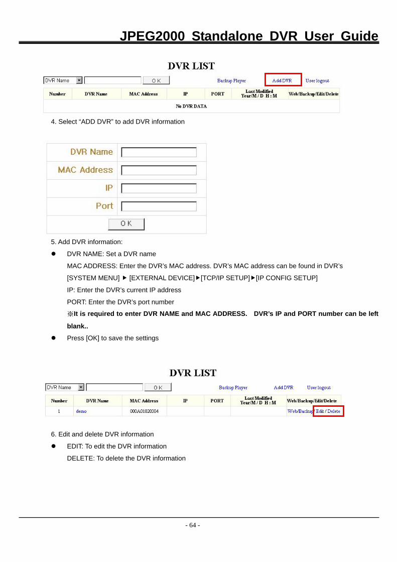
4. Select “ADD DVR” to add DVR information
5. Add DVR information:
DVR NAME: Set a DVR name
MAC ADDRESS: Enter the DVR’s MAC address. DVR’s MAC address can be found in DVR’s
[SYSTEM MENU] [EXTERNAL DEVICE] [TCP/IP SETUP] [IP CONFIG SETUP]
IP: Enter the DVR’s current IP address
PORT: Enter the DVR’s port number
※It is required to enter DVR NAME and MAC ADDRESS. DVR’s IP and PORT number can be left
blank..
Press [OK] to save the settings
6. Edit and delete DVR information
EDIT: To edit the DVR information
DELETE: To delete the DVR information
JPEG2000 Standalone DVR User Guide
- 65 -
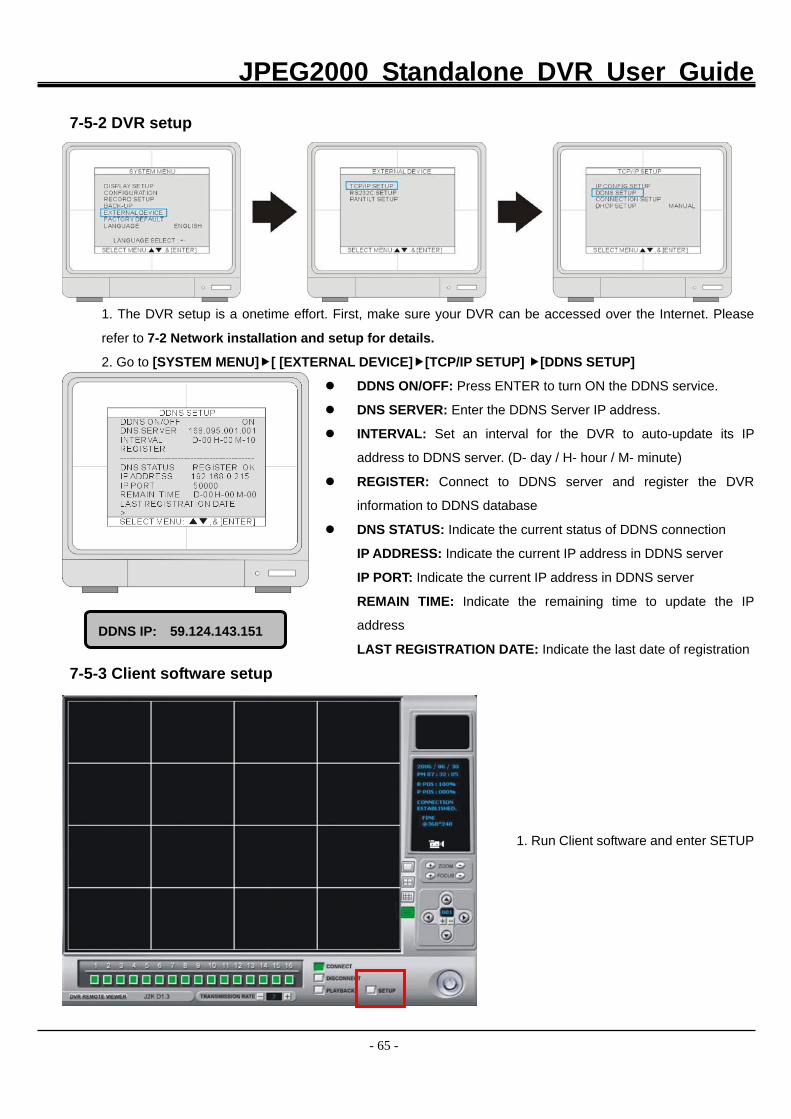
7-5-2 DVR setup
1. The DVR setup is a onetime effort. First, make sure your DVR can be accessed over the Internet. Please
refer to 7-2 Network installation and setup for details.
2. Go to [SYSTEM MENU] [ [EXTERNAL DEVICE] [TCP/IP SETUP] [DDNS SETUP]
DDNS ON/OFF: Press ENTER to turn ON the DDNS service.
DNS SERVER: Enter the DDNS Server IP address.
INTERVAL: Set an interval for the DVR to auto-update its IP
address to DDNS server. (D- day / H- hour / M- minute)
REGISTER: Connect to DDNS server and register the DVR
information to DDNS database
DNS STATUS: Indicate the current status of DDNS connection
IP ADDRESS: Indicate the current IP address in DDNS server
IP PORT: Indicate the current IP address in DDNS server
REMAIN TIME: Indicate the remaining time to update the IP
address
LAST REGISTRATION DATE: Indicate the last date of registration
7-5-3 Client software setup
1. Run Client software and enter SETUP
DDNS IP: 59.124.143.151
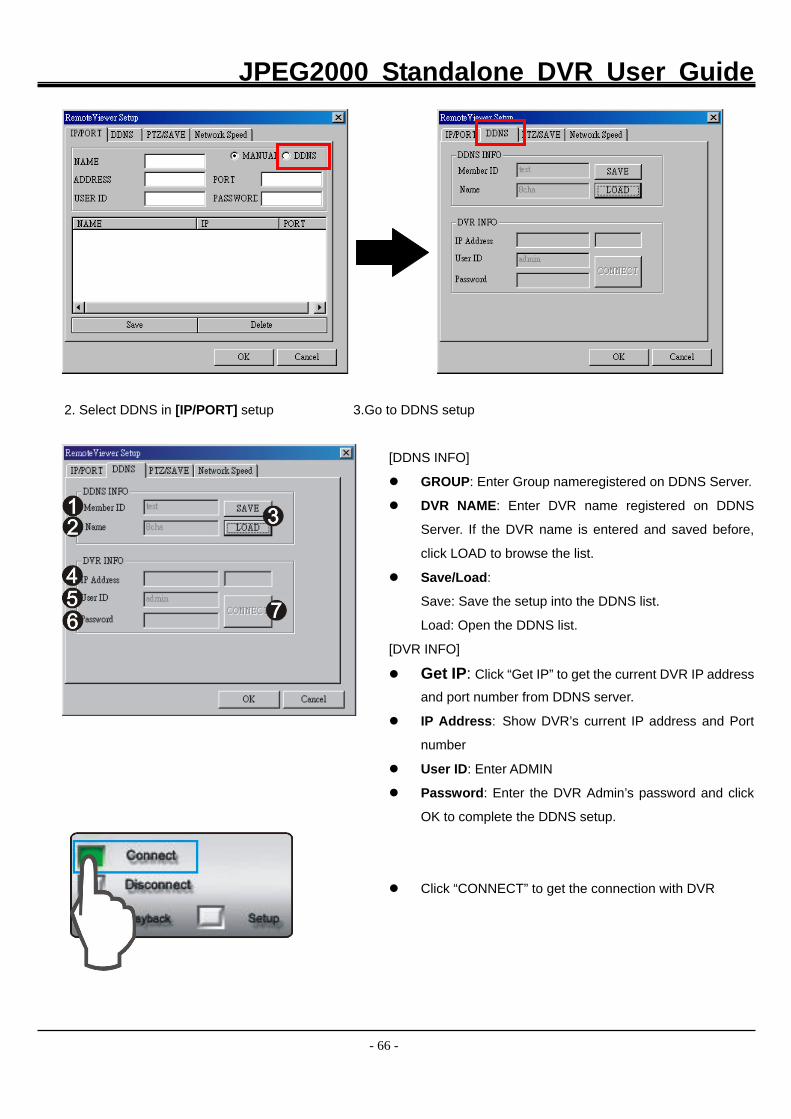
JPEG2000 Standalone DVR User Guide
- 66 -
2. Select DDNS in [IP/PORT] setup 3.Go to DDNS setup
[DDNS INFO]
GROUP: Enter Group nameregistered on DDNS Server.
DVR NAME: Enter DVR name registered on DDNS
Server. If the DVR name is entered and saved before,
click LOAD to browse the list.
Save/Load:
Save: Save the setup into the DDNS list.
Load: Open the DDNS list.
[DVR INFO]
Get IP: Click “Get IP” to get the current DVR IP address
and port number from DDNS server.
IP Address: Show DVR’s current IP address and Port
number
User ID: Enter ADMIN
Password: Enter the DVR Admin’s password and click
OK to complete the DDNS setup.
Click “CONNECT” to get the connection with DVR
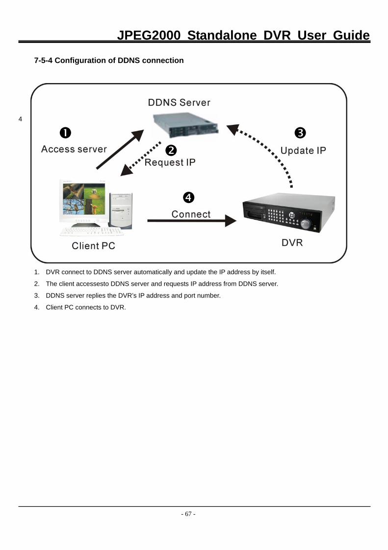
JPEG2000 Standalone DVR User Guide
- 67 -
7-5-4 Configuration of DDNS connection
4
1. DVR connect to DDNS server automatically and update the IP address by itself.
2. The client accessesto DDNS server and requests IP address from DDNS server.
3. DDNS server replies the DVR’s IP address and port number.
4. Client PC connects to DVR.
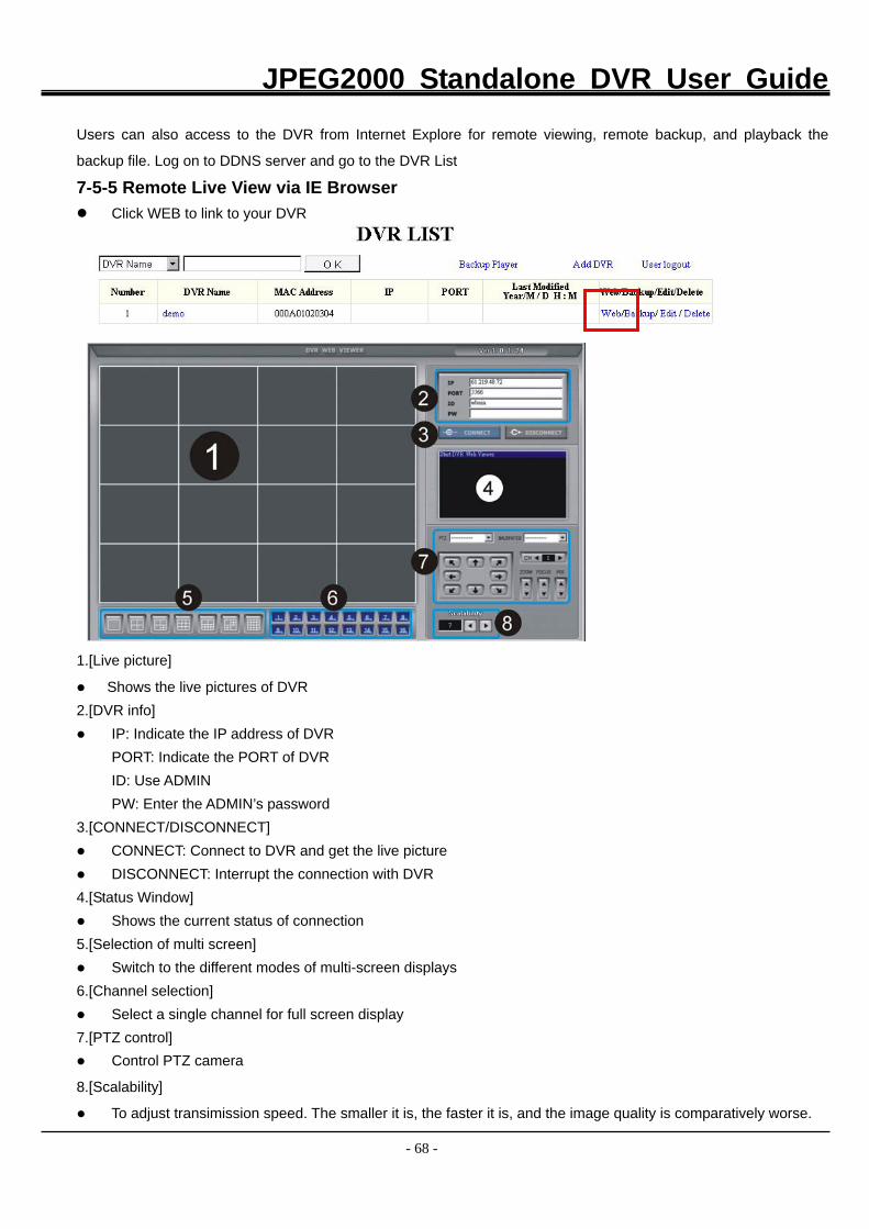
JPEG2000 Standalone DVR User Guide
- 68 -
Users can also access to the DVR from Internet Explore for remote viewing, remote backup, and playback the
backup file. Log on to DDNS server and go to the DVR List
7-5-5 Remote Live View via IE Browser Click WEB to link to your DVR
1.[Live picture]
Shows the live pictures of DVR 2.[DVR info]
IP: Indicate the IP address of DVR PORT: Indicate the PORT of DVR ID: Use ADMIN PW: Enter the ADMIN’s password 3.[CONNECT/DISCONNECT]
CONNECT: Connect to DVR and get the live picture DISCONNECT: Interrupt the connection with DVR
4.[Status Window] Shows the current status of connection
5.[Selection of multi screen] Switch to the different modes of multi-screen displays
6.[Channel selection] Select a single channel for full screen display
7.[PTZ control] Control PTZ camera
8.[Scalability]
To adjust transimission speed. The smaller it is, the faster it is, and the image quality is comparatively worse.
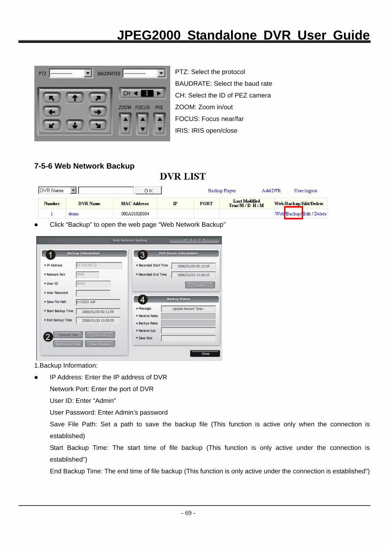
JPEG2000 Standalone DVR User Guide
- 69 -
PTZ: Select the protocol
BAUDRATE: Select the baud rate
CH: Select the ID of PEZ camera
ZOOM: Zoom in/out
FOCUS: Focus near/far
IRIS: IRIS open/close
7-5-6 Web Network Backup
Click “Backup” to open the web page “Web Network Backup”
1.Backup Information:
IP Address: Enter the IP address of DVR
Network Port: Enter the port of DVR
User ID: Enter “Admin”
User Password: Enter Admin’s password
Save File Path: Set a path to save the backup file (This function is active only when the connection is
established)
Start Backup Time: The start time of file backup (This function is only active under the connection is
established”)
End Backup Time: The end time of file backup (This function is only active under the connection is established”)
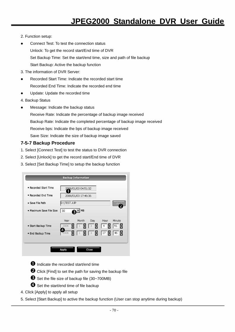
JPEG2000 Standalone DVR User Guide
- 70 -
2. Function setup:
Connect Test: To test the connection status
Unlock: To get the record start/End time of DVR
Set Backup Time: Set the start/end time, size and path of file backup
Start Backup: Active the backup function
3. The information of DVR Server:
Recorded Start Time: Indicate the recorded start time
Recorded End Time: Indicate the recorded end time
Update: Update the recorded time
4. Backup Status
Message: Indicate the backup status
Receive Rate: Indicate the percentage of backup image received
Backup Rate: Indicate the completed percentage of backup image received
Receive bps: Indicate the bps of backup image received
Save Size: Indicate the size of backup image saved
7-5-7 Backup Procedure 1. Select [Connect Test] to test the status to DVR connection
2. Select [Unlock] to get the record start/End time of DVR
3. Select [Set Backup Time] to setup the backup function
Indicate the recorded start/end time Click [Find] to set the path for saving the backup file Set the file size of backup file (30~700MB) Set the start/end time of file backup
4. Click [Apply] to apply all setup
5. Select [Start Backup] to active the backup function (User can stop anytime during backup)
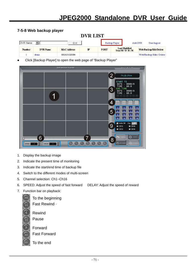
JPEG2000 Standalone DVR User Guide
- 71 -
7-5-8 Web backup player
Click [Backup Player] to open the web page of “Backup Player”
1. Display the backup image
2. Indicate the present time of monitoring
3. Indicate the start/end time of backup file
4. Switch to the different modes of multi-screen
5. Channel selection: Ch1~Ch16
6. SPEED: Adjust the speed of fast forward DELAY: Adjust the speed of reward
7. Function bar on playback:
To the beginning Fast Rewind。
Rewind Pause
Forward Fast Forward
To the end
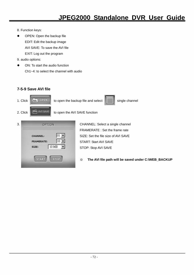
JPEG2000 Standalone DVR User Guide
- 72 -
8. Function keys:
OPEN: Open the backup file
EDIT: Edit the backup image
AVI SAVE: To save the AVI file
EXIT: Log out the program
9. audio options:
ON: To start the audio function
Ch1~4: to select the channel with audio
7-5-9 Save AVI file
1. Click to open the backup file and select single channel
2. Click to open the AVI SAVE function
3. CHANNEL: Select a single channel
FRAMERATE : Set the frame rate
SIZE: Set the file size of AVI SAVE
START: Start AVI SAVE
STOP: Stop AVI SAVE
※ The AVI file path will be saved under C:\WEB_BACKUP
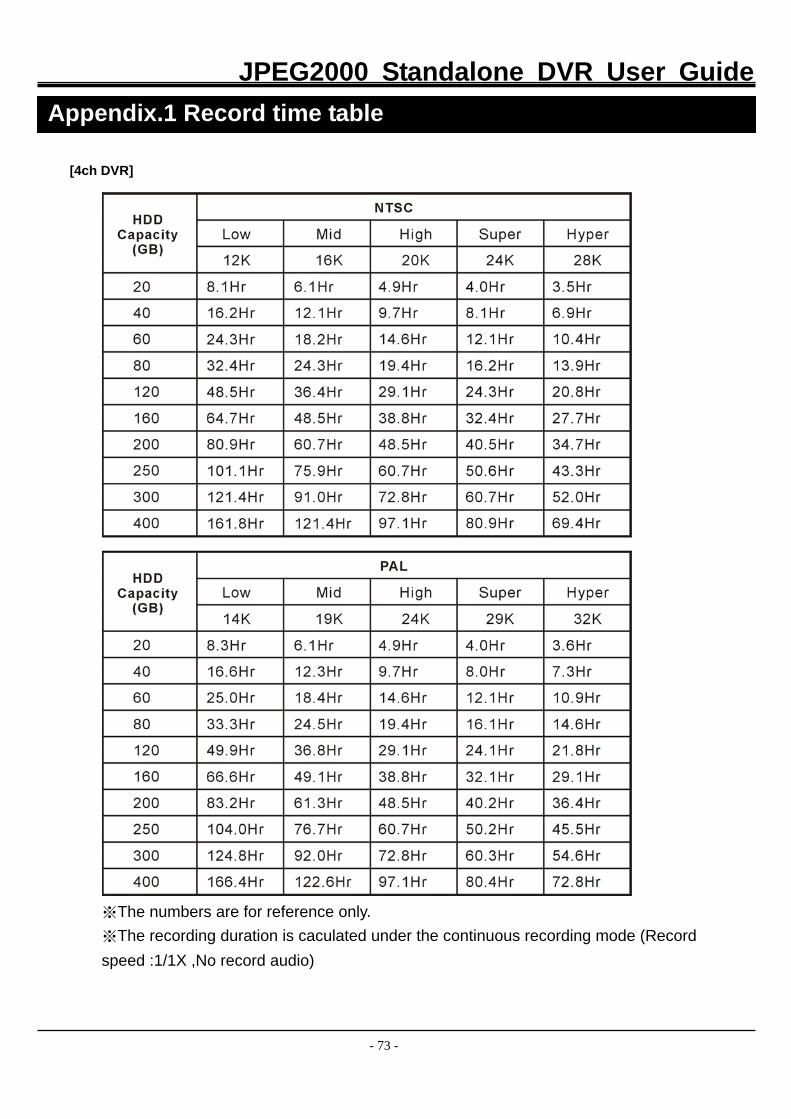
JPEG2000 Standalone DVR User Guide
- 73 -
[4ch DVR]
※The numbers are for reference only. ※The recording duration is caculated under the continuous recording mode (Record speed :1/1X ,No record audio)
Appendix.1 Record time table
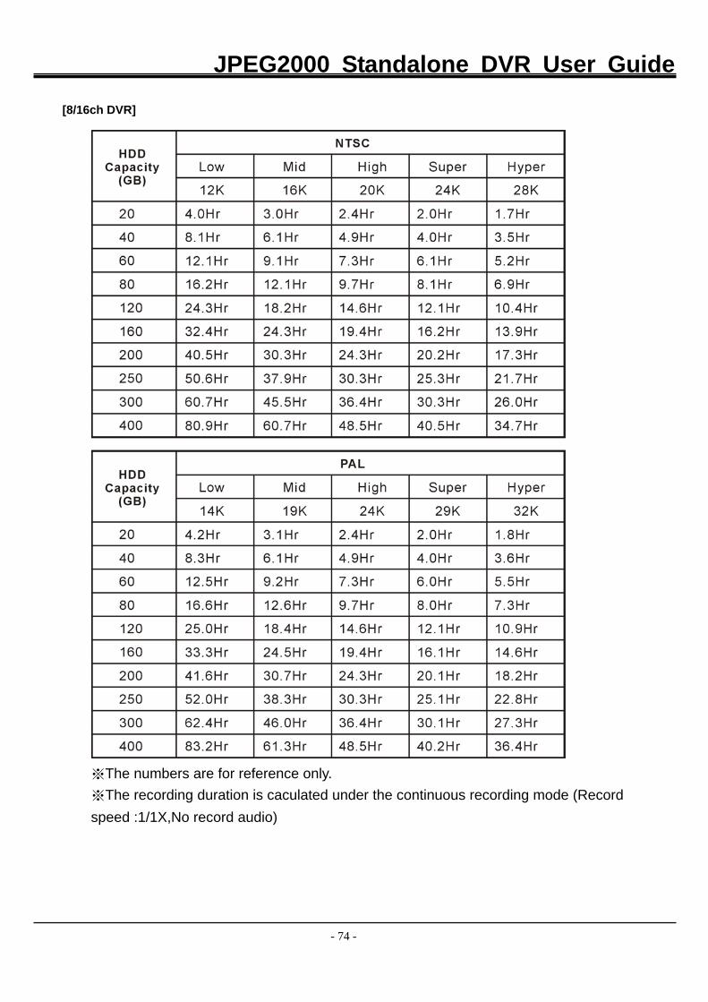
JPEG2000 Standalone DVR User Guide
- 74 -
[8/16ch DVR]
※The numbers are for reference only. ※The recording duration is caculated under the continuous recording mode (Record speed :1/1X,No record audio)
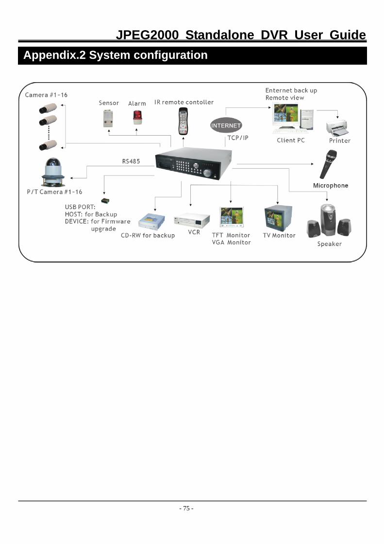
JPEG2000 Standalone DVR User Guide
- 75 -
Appendix.2 System configuration
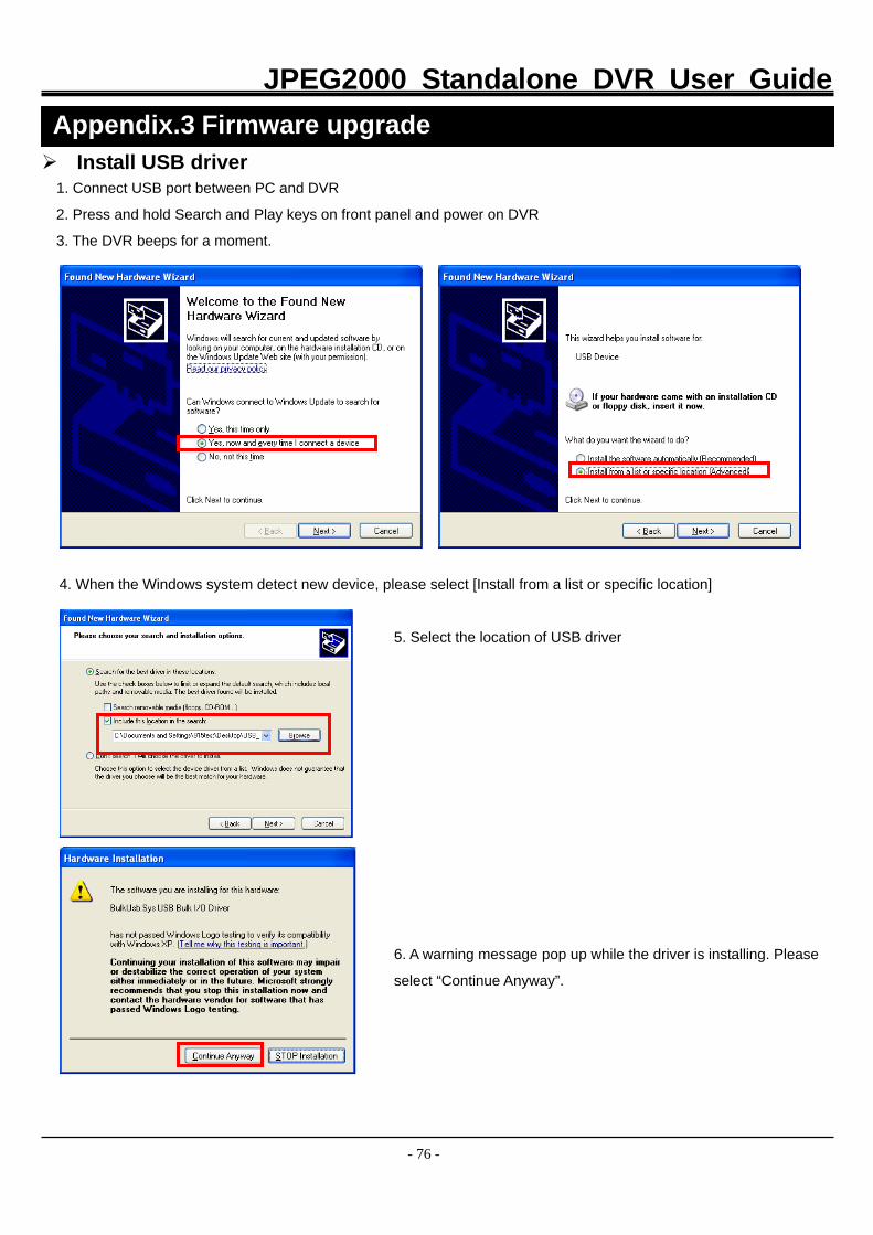
JPEG2000 Standalone DVR User Guide
- 76 -
Install USB driver 1. Connect USB port between PC and DVR
2. Press and hold Search and Play keys on front panel and power on DVR
3. The DVR beeps for a moment. 4. When the Windows system detect new device, please select [Install from a list or specific location]
5. Select the location of USB driver
6. A warning message pop up while the driver is installing. Please
select “Continue Anyway”.
Appendix.3 Firmware upgrade
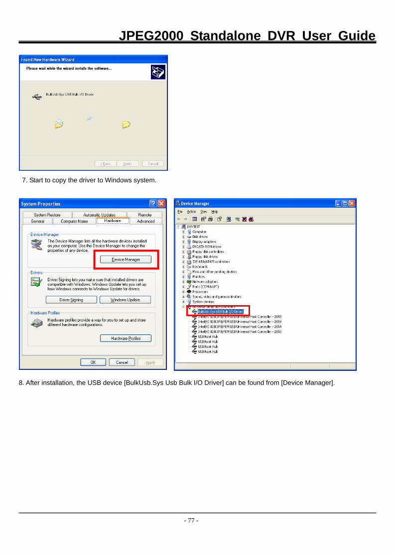
JPEG2000 Standalone DVR User Guide
- 77 -
7. Start to copy the driver to Windows system.
8. After installation, the USB device [BulkUsb.Sys Usb Bulk I/O Driver] can be found from [Device Manager].
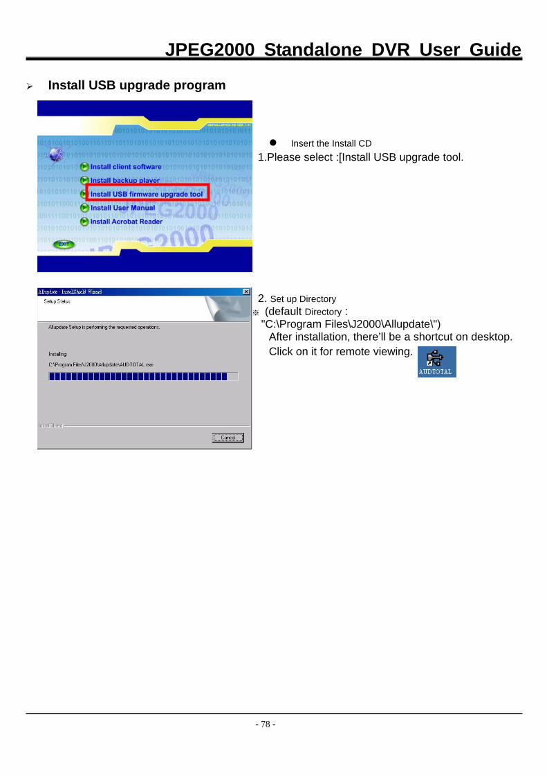
JPEG2000 Standalone DVR User Guide
- 78 -
Install USB upgrade program
Insert the Install CD 1.Please select :[Install USB upgrade tool.
2. Set up Directory ※ (default Directory : "C:\Program Files\J2000\Allupdate\")
After installation, there’ll be a shortcut on desktop. Click on it for remote viewing.
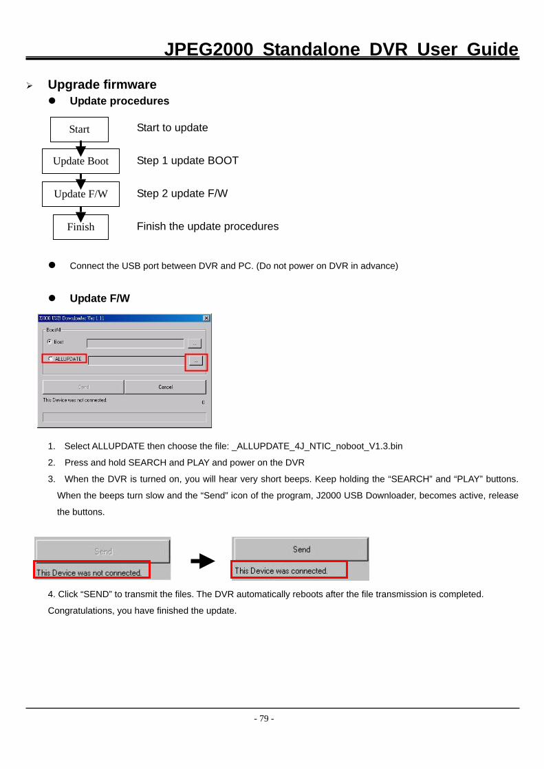
JPEG2000 Standalone DVR User Guide
- 79 -
Upgrade firmware
Update procedures
Connect the USB port between DVR and PC. (Do not power on DVR in advance)
Update F/W
1. Select ALLUPDATE then choose the file: _ALLUPDATE_4J_NTIC_noboot_V1.3.bin
2. Press and hold SEARCH and PLAY and power on the DVR
3. When the DVR is turned on, you will hear very short beeps. Keep holding the “SEARCH” and “PLAY” buttons.
When the beeps turn slow and the “Send” icon of the program, J2000 USB Downloader, becomes active, release
the buttons.
4. Click “SEND” to transmit the files. The DVR automatically reboots after the file transmission is completed.
Congratulations, you have finished the update.
Step 1 update BOOT
Step 2 update F/W
Start
Update Boot
Update F/W
Finish Finish the update procedures
Start to update
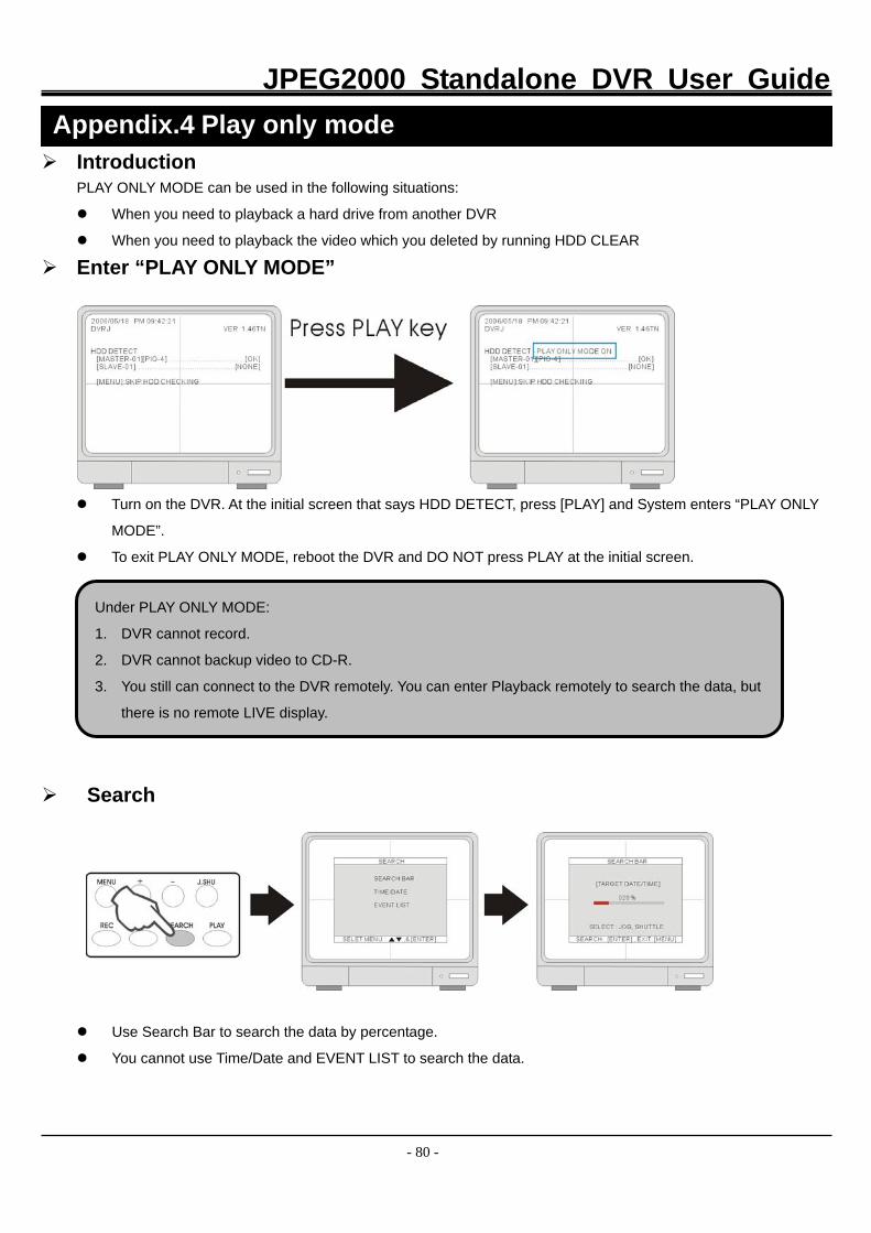
JPEG2000 Standalone DVR User Guide
- 80 -
Introduction PLAY ONLY MODE can be used in the following situations:
When you need to playback a hard drive from another DVR
When you need to playback the video which you deleted by running HDD CLEAR
Enter “PLAY ONLY MODE”
Turn on the DVR. At the initial screen that says HDD DETECT, press [PLAY] and System enters “PLAY ONLY
MODE”.
To exit PLAY ONLY MODE, reboot the DVR and DO NOT press PLAY at the initial screen.
Search
Use Search Bar to search the data by percentage.
You cannot use Time/Date and EVENT LIST to search the data.
Appendix.4 Play only mode
Under PLAY ONLY MODE:
1. DVR cannot record.
2. DVR cannot backup video to CD-R.
3. You still can connect to the DVR remotely. You can enter Playback remotely to search the data, but
there is no remote LIVE display.