Embed Size (px)
Citation preview

def jPM SERIES GEAR UNITS
SINGLE REDUCTION WORMGEAR UNITS
INSTALLATION & MAINTENANCE GUIDE
March 2010
def jPM Series Gears INSTALLATION & MAINTENANCE GUIDE
2
IMPORTANT INFORMATION YOU MUST READ Product Safety Information of def Gear Products
Important Notes Always isolate the power source from the drive or the equipment. Always wear protective clothing, safety glasses, hats, gloves, ear protectors and safety shoes as warranted by the circumstances. Always ensure tools are in good working condition and use as directed by the manufacturer. Loosen all tension devices. Ensure that the correct lubrication is used prior to commissioning. Customers are reminded that when purchasing any technical product for use at work (or otherwise), any additional or up-to-date information and guidance, which it has not been possible to include in the publication, should be obtained from your local sales office in relation to the suitability and the safety and proper use of the product. All relevant information and guidance must be passed on by you to the person engaged in, or likely to be affected by or responsible for the use of the product. Potential Hazards There are a number of hazards that must be avoided when installing, maintaining and repairing Renold Gear units. The following are suggested safety guides when undertaking any of the above. Hot surfaces and lubricants. After prolonged running, a gear unit can generate high temperatures and can create surface temperatures that could burn the skin. Do not drain the oil from a gear unit that has been run for a prolonged period because the oil will be hot and could burn the skin. Allow the oil to cool, prior to draining. Fire and Explosions. A gear unit creates an oil mist or vapour internally after prolonged running and can be a fire and explosion risk if a naked flame is in close proximity. Allow the unit to cool prior to opening the unit. Flames or high running temperatures can burn or melt rubber compounds and melt plastic compounds and produce dangerous fumes. These compounds should be avoided until cool and then handled with protective gloves. Guards All rotating parts must be guarded with suitable guards, secured to the gear unit or machine frame. Lifting Lifting lugs or lifting points to suit eyebolts are provided on all Renold gear units. These must be used at all times. Noise Gear units run at high speed can create noise levels damaging to hearing. Ear protectors should be worn if there is a possibility of prolonged exposure to these conditions. Lubrication. The Installation & Maintenance Guide include the various types and quantities/ types of oils to be used in Renold gear units. These must be followed at all times. Electrical Equipment Follow all associated manufacturers instructions and always isolate all electrical equipment prior to carrying out any work. Holdback/ Backstops Failure of a backstop when fitted to the gear unit could result in personnel injury and machine damage. Secondary back-up systems must be provided. Installation Maintenance and Storage. Full Installation & Maintenance instructions are included in this document. Failure to follow the instructions could result in failure of the gear unit and / or damage to the equipment onto which it is being installed. General Short and long term storage instructions have been in included in this Installation & Maintenance Guide. All information contained in this document is subject to change without notice. The right is reserved to make modifications to the product to meet manufacturing conditions and/or developments (for example in design or materials) Copyright Renold Power Transmission Limited 2002. All rights reserved. Nothing containing in this publication shall constitute a part of any contract, express or implied. � RENOLD GEARS TEL: + 44 [0] 1706 751000 HOLROYD GEAR WORKS FAX: + 44 [0] 1706 751001 MILNROW eMAIL: [email protected] ROCHDALE OL16 3LS ENGLAND WEB: www.renold.com
def jPM Series Gears INSTALLATION & MAINTENANCE GUIDE
3
CONTENTS Section Description Page No. 1. Unit Designation Code……………………………………………… 4 2. General Information………………………………………………… 4
3. Weather Protection …………………………………………………. 4 4. Pre-Installation……………………………………………………… 5 4.1 Plug Positions 4.2 Fixing Surfaces 5. Installation…………………………………………………………... 5 5.1 Fitting Of Components Onto Input/Output Shafts 5.2 Unit Location Requirements 5.3 Fitting Gear Unit To Customer’s Equipment 5.4 Connecting The Motor Supply 5.5 Installing Foot Mounted Gear Units 5.6 Installing Flange Mounted Gear Units 5.7 Installing Shaft Mounted Gear Units (Turnbuckle Restraint) 5.8 Installing Shaft Mounted Gear Units (Torque Restraint Bracket) 6. Lubrication…………………………………………………………. 9 6.1 Gear Unit Lubrication Requirements 6.2 Lubrication Quantities 6.3 Recommended Lubricants 6.4 Applying Lubrication To The Gear Unit 6.5 Draining Lubrication From The Gear Unit 7. Running-in Of Gear Units................................................................ 10 8. Gear Unit Routine Maintenance…………………………………... 10 8.1 Periodic Instructions 8.2 Renewing The Lubricant 9. Motor Routine Maintenance……………………………………….. 10 9.1 Periodic Instructions 9.2 Motor Lubrication 9.3 Greasing Interval 10. Storing The Gear Unit………………………………………………. 11 11. Atex Approval………………………………………………………. 12 APPENDIX Appendix A………………………………………………………… 13 - 14 Appendix B………………………………………………………… 15 Appendix C………………………………………………………… 16 - 17 Appendix D………………………………………………………… 18 – 19 Appendix E………………………………………………………… 20
def jPM Series Gears INSTALLATION & MAINTENANCE GUIDE
4
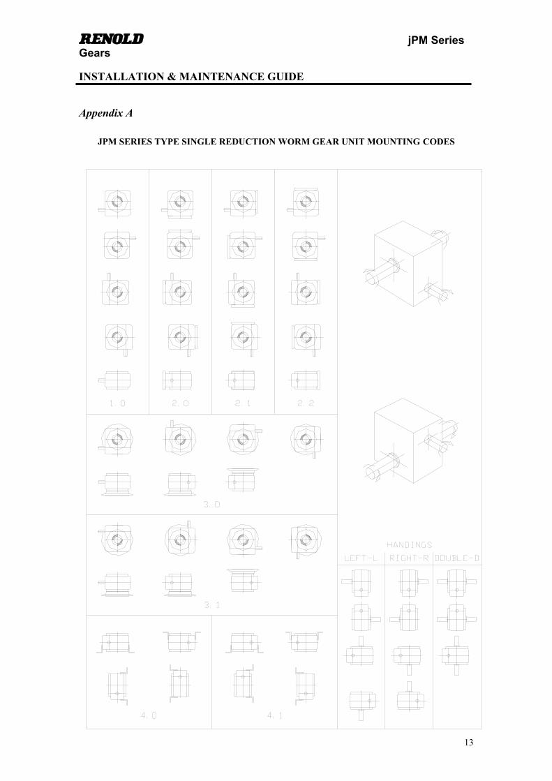
1. UNIT DESIGNATION CODE If further information of after sales service is required, please have the following information at hand. - Order No. - Unit Designation Code Examples jPM - MOTORISED UNIT jPM 17 M 71 2.0 R 30 jPM Unit size 17 (4 sizes - 17, 22, 26 & 30) M Motorised unit 71 Motor frame size 63, 71, 80, 90, 100, 112 2.0 Unit mounting detail (see Appendix A) R Unit handing (see Appendix A) 30 Ratio jPM - MOTOR READY UNIT - to suit free issue motor jPM 17 A 71 2.0 R 30 jPM Unit size 17 (4 sizes - 17, 22, 26 & 30) A Motor ready unit to suit customers motor
All other details as above jPM - REDUCTION GEAR OR SPEED REDUCER UNIT jPM 17 H 2.0 R 30 jPM Unit size 17 (4 sizes - 17, 22, 26 & 30) H Reduction gear type All other details as above
2. GENERAL INFORMATION The jPM Series of gear units are comprised of four sizes ranging from 1.75”-3” centres. The units can be supplied either as reduction gears, geared motors, or as motor ready gear units for individual customers to fit their own motors. Rated up to 397 Nm , in a ratio range from 5:1 up to 70:1.jPM Series as a single reduction gear unit and offers a wide selection of mounting options and accessories to suit a wide and diverse market. The instructions which follow are to help you achieve the recommended installation procedure, ensuring optimum performance, satisfaction and life from your Renold Gears jPM Series gear unit. Prior to despatch, all units are tested and checked to ensure that they comply with the highest standards required by our company. Also, a great deal of care is taken in the quality of packing and transport arrangements, ensuring that the unit reaches its final destination in its original condition. Renold Gears hopes that the supplied unit will fully meet your expectations.
3. WEATHER PROTECTION All jPM Series gear units are protected to a standard capable of withstanding normal weather conditions. Where it is probable that the unit will be subjected to adverse weather conditions, or where it is to be left inactive for a long period of time, our sales team should be notified when the order is placed so that the unit can be provided with the appropriate protection.
def jPM Series Gears INSTALLATION & MAINTENANCE GUIDE
5
4. PRE-INSTALLATION 4.1 PLUG POSITIONS jPM Series gear units are fitted with oil breather and drain plugs. The units are designed for mounting in any of the positions shown in Appendix A. Using the diagrams provided, to ensure that the plugs are in the correct position for the intended mounting position. If required, a breather containing a filter can be ordered, for use where conditions could lead to dirt or water penetration of the breather.
4.2 FIXING SURFACES Before starting to install the jPM Series gear unit, any areas which are used to locate or have fittings attached to them, must be cleaned to remove any dirt, paint or grease which may be present. The same precautions must be taken with any other equipment being assembled. Cleansing the mating faces of the gear unit and its fitting area will ensure that the unit sits flat on the mounting area. This will in turn aid the necessary alignment of the gear unit. 5. INSTALLATION
NOTE: Units are supplied with oil for the mounting position specified on the order.
5.1 FITTING OF COMPONENTS ONTO INPUT/OUTPUT SHAFTS Components which are to be fitted to either the input or output shaft of the gear unit (e.g. couplings, pulleys, sprockets, etc.) may be fitted using one of the following methods.
NOTE: Do not strike the component onto the shaft with a mallet, as this could damage the support bearings.
The component can be heated using an appropriate method, expanding the bore. The part can then be
dropped, lightly tapped, or jacked onto the shaft, depending on the fit of the item. The component may be applied to the shaft using a screw jack method which locates in the tapped
hole situated in the end of the shaft. Please refer to Appendix B for the tapped hole dimensions relative to the size of shaft.
NOTE: Gear units supplied for the American market will have shaft diameters to a nominal imperial size. A tapped hole will not be present in the end of the shaft.
5.2 UNIT LOCATION REQUIREMENTS Foot / Flange Mounted Gear Units The gear unit and other drive components should be rigidly mounted onto firm and preferably flat foundations. This prevents any movement and vibration which may affect the alignment of the shafts, couplings, pulleys, etc. If required, suitable baseplates to incorporate the unit can be supplied by Renold Gears.

def jPM Series Gears INSTALLATION & MAINTENANCE GUIDE
6
Shaft Mounted Gear Units The shaft onto which the gear unit is to be fitted must be a close sliding fit into the sleeve of the gear unit. The key in the mating shaft must be a good side fit and of sufficient length to present a full face to the keyway in the sleeve over the length of the locating bore.
5.3 FITTING GEAR UNIT TO CUSTOMER’S EQUIPMENT When fitting an jPM Series gear unit to its allocated position using a flange/skirt or the gear case feet, use hexagon head screws/bolts complying to ISO grade 8.8 as a minimum, and tighten to the relevant torque (shown below)
Nominal Bolt Dia. Tightening Torque (Nm)
M6 11.7 M8 28
M10 56 M12 98
5.4 CONNECTING THE MOTOR SUPPLY Mains Connection Motor connection to the mains supply should be carried out by a competent, fully qualified electrician. The current rating of the motor is located on the motor identification plate.
NOTE: The correct sizing of cables to electrical regulations is essential.
Motor Where units are supplied with motors, connection to the motor terminal box should be carried out using the circuit diagrams contained in Appendix C. Motors which are supplied or requested by the customer which are non-standard to the gear unit, should have the relevant circuit diagrams provided with them. Motor With Brake For brake motors, please refer to the circuit diagrams which will be supplied with the motor. 5.5 INSTALLING FOOT MOUNTED GEAR UNITS
NOTE: Before commencing installation, ensure that all pre-installation tasks in Section 4 have been executed.
The following instructions are the recommended procedures for the fitting and location of foot mounted jPM Series gear units. Standard jPM Series units are free standing gearboxes. If required, they can be supplied with a suitable baseplate provided that is requirement is stipulated on the purchase order. I. Firstly, ensure that the foundation where the unit is to be positioned is suitable (as stated in Section
4.3) and is not distorted.

def jPM Series Gears INSTALLATION & MAINTENANCE GUIDE
7
II. Position the unit in its allocated position (preferably on the same foundation/baseplate as the driven unit). Secure unit to the foundation using the relevant size and grade of bolts. Tighten the bolts slightly.
III. Align the unit using an appropriate technique. (Refer to Appendix D.) When alignment is complete,
tighten feet bolts to the appropriate torque for that particular size of bolt (Section 4.4) and re-check unit alignment.
IV. Secure protective guarding around the equipment in accordance with the relevant standards.
WARNING: All rotating equipment must be provided with suitable guarding before running, or injury may result.
VI. Finally connect the motor to the power supply (Section 4.5) ensuring that the correct direction of
rotation is achieved. 5.6 INSTALLING FLANGE MOUNTED GEAR UNITS
NOTE: Before commencing installation, ensure that all pre-installation tasks in Section 4 have been executed.
The following instructions are the recommended procedures for the fitting and location of flange mounted jPM Series gear units. I. Firstly, ensure that the foundation where the unit is to be positioned is suitable (as stated in Section
4.3) and is not distorted. II. Locate the unit in the appropriate mounting position. III. Secure the unit to the mounting face using the appropriate size and grade of bolts and tighten to the
correct torque (Section 4.4). IV. Secure protective guarding around the equipment in accordance with the relevant standards.
WARNING: All rotating equipment must be provided with suitable guarding before running,or injury may result.
VI. Finally connect the motor to the power supply (Section 4.5) ensuring that the correct direction of
rotation is achieved. 5.7 INSTALLING SHAFT MOUNTED GEAR UNITS (TURNBUCKLE
RESTRAINT)
NOTE: Before commencing installation, ensure that all pre-installation tasks in Section 4 have been executed.
For instances where the customer is to supply the torque restraint, it must be ensured that a substantial clearance is provided for the fixing member, to allow for eccentricity of the drive shaft and bearings. The following instructions are the recommended procedures for the fitting and location of shaft mounted jPM Series gear units. I. Firstly, ensure that the shaft onto which the unit is to be mounted is suitable (as stated in Section
4.3) and is running true.
def jPM Series Gears INSTALLATION & MAINTENANCE GUIDE
8
II. Fit the required key into the shaft and coat both the shaft and key with anti- scuffing paste. III. Locate and secure the unit onto the mounting shaft using the most appropriate method available.
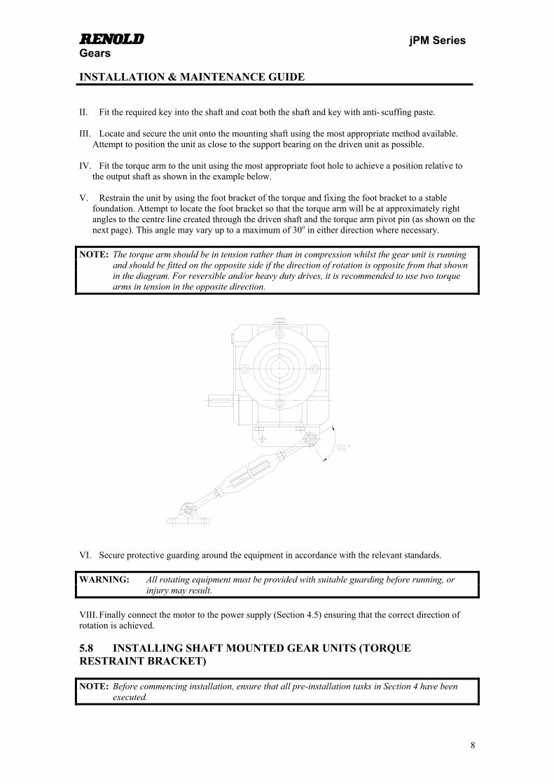
Attempt to position the unit as close to the support bearing on the driven unit as possible. IV. Fit the torque arm to the unit using the most appropriate foot hole to achieve a position relative to
the output shaft as shown in the example below. V. Restrain the unit by using the foot bracket of the torque and fixing the foot bracket to a stable
foundation. Attempt to locate the foot bracket so that the torque arm will be at approximately right angles to the centre line created through the driven shaft and the torque arm pivot pin (as shown on the next page). This angle may vary up to a maximum of 30o in either direction where necessary.
NOTE: The torque arm should be in tension rather than in compression whilst the gear unit is running and should be fitted on the opposite side if the direction of rotation is opposite from that shown in the diagram. For reversible and/or heavy duty drives, it is recommended to use two torque arms in tension in the opposite direction.
VI. Secure protective guarding around the equipment in accordance with the relevant standards.
WARNING: All rotating equipment must be provided with suitable guarding before running, or injury may result.
VIII. Finally connect the motor to the power supply (Section 4.5) ensuring that the correct direction of rotation is achieved. 5.8 INSTALLING SHAFT MOUNTED GEAR UNITS (TORQUE RESTRAINT BRACKET)
NOTE: Before commencing installation, ensure that all pre-installation tasks in Section 4 have been executed.
def jPM Series Gears INSTALLATION & MAINTENANCE GUIDE
9
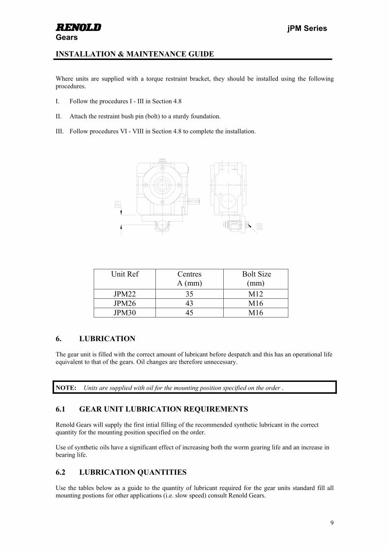
Where units are supplied with a torque restraint bracket, they should be installed using the following procedures. I. Follow the procedures I - III in Section 4.8 II. Attach the restraint bush pin (bolt) to a sturdy foundation. III. Follow procedures VI - VIII in Section 4.8 to complete the installation.
Unit Ref Centres A (mm)
Bolt Size (mm)
JPM22 35 M12 JPM26 43 M16 JPM30 45 M16
6. LUBRICATION The gear unit is filled with the correct amount of lubricant before despatch and this has an operational life equivalent to that of the gears. Oil changes are therefore unnecessary.
NOTE: Units are supplied with oil for the mounting position specified on the order .
6.1 GEAR UNIT LUBRICATION REQUIREMENTS Renold Gears will supply the first intial filling of the recommended synthetic lubricant in the correct quantity for the mounting position specified on the order. Use of synthetic oils have a significant effect of increasing both the worm gearing life and an increase in bearing life. 6.2 LUBRICATION QUANTITIES Use the tables below as a guide to the quantity of lubricant required for the gear units standard fill all mounting postions for other applications (i.e. slow speed) consult Renold Gears.
def jPM Series Gears INSTALLATION & MAINTENANCE GUIDE
10
Unit Ref Underdriven/Overdirven/Vertical Input (Litres)
JPM22 0.65 JPM30 0.85 JPM30 1.45
6.3 RECOMMENDED LUBRICANTS A list of the approved lubricants is included in Appendix E of this manual.
7. RUNNING-IN OF GEAR UNITS Prior to despatch, all units are subjected to a short running-in period. However, many hours of running under full load are required for the unit to attain its maximum efficiency. Where necessary, the gear unit may be put to work immediately; but where possible it is advantageous, with regards to the overall life of the gear unit, for the gearbox to be run in under gradually increasing loads, until full load is attained after a period between approximately 20 to 40 hours. Reasonable precautions should be taken to assure that overloads do not occur during the early stages of running the gear unit. 8. GEAR UNIT ROUTINE MAINTENANCE 8.1 PERIODIC INSTRUCTIONS The main inspections which are required for the gear unit are as follows:- I. The filler/breather plug must be examined at least once a month to ensure that the breather hole is free
from dirt or grease. Clean if required. II. Check for any lubricant leaking from the unit. Leakage from any of the plugs in the unit can be solved
by removing the plug (drain the unit if necessary), add a suitable sealing medium to the threads of the plug, and re-fit the plug to the gear unit. If leaking is apparent from any other location, please note the position and contact your nearest outlet (Addresses are displayed on the back cover.)
9. MOTOR ROUTINE MAINTENANCE 9.1 PERIODIC INSTRUCTIONS Totally enclosed fan cooled three phase squirrel cage induction motors require very little maintenance. Nevertheless, it is recommended to check the motor regularly in order to prevent a breakdown caused by dust, moisture, vibration, too much or too little greasing. The following simple checks should help ensure the longevity of the motor:- I. The outer parts of the motor, especially the cooling ribs and cooling channels, have to be kept as clean
as possible in order not to obstruct the passage of air generated by the fan to allow of heat exchange. II. Motors which are not often run, should be started periodically to prevent moisture affecting the
windings in the long term. III.Due to vibration, the bolts fastening the motor to the gear unit should be examined to ensure that they
have not worked loose.
def jPM Series Gears INSTALLATION & MAINTENANCE GUIDE
11
9.2 MOTOR BEARINGS LUBRICATION Motors which have been supplied by Renold Gears will have bearings pre-filled with a high quality Lithium-based grease. Motor sizes D71 to D112 are provided with shielded/sealed bearings, which have been pre-filled and greased-for-life by the bearing manufacturer. Motors with sealed bearings and no re-lubrication system require no maintenance apart from noise and temperature checks and the checks stated in Section 9.1. 10. STORING THE GEAR UNIT Gear units which are to be stored or left inactive for long periods of time should be adequately protected, particularly those units situated on exposed sites and/or operating in corrosive or salty atmospheres. The following precautions will generally be adequate for protecting the unit, but advice concerning the protection of particular units can be given if required.
10.1 SHORT TERM STORAGE (UP TO 12 MONTHS) I. The location should be free from vibration, otherwise brinelling could take place, particularly between
bearing rolling elements and raceways, leading to noisy operation and early failure in service. Wherever possible, the shafts of the unit should be rotated at least once a week, by hand if necessary, to prevent brinelling.
II. All external finish machined and unprotected surfaces should be spray coated with a anti-corrosion
rust inhibitor. III. After spraying, all shafts should be wrapped in anti-corrosion rust inhibitor paper. IV. Where the unit is empty of oil, spray the gearcase interior with rust preventative oil, which is
compatible with the recommended lubricant. V. Where the unit is filled with oil, operate at full speed once per month for not less than 10 minutes, to
ensure that all of the internal components receive a liberal coating of oil. 10.2 LONG TERM STORAGE (FROM 12 MONTHS UP TO 2 YEARS) I. The location should be free from vibration, otherwise brinelling could take place, particularly between
bearing rolling elements and raceways, leading to noisy operation and early failure in service. Wherever possible, the shafts of the unit should be rotated at least once a week, by hand if necessary, to prevent brinelling.
II. Apply Denso paste and tape to all external finish machined and unprotected surfaces, including shaft
extensions, ensuring full coverage to lip of oilseal. III. Completely fill the unit with oil, ensuring complete submersion of all internal components. When the
unit is returned to service, drain and refill with new lubricant to the correct level (Sections 6.4 & 6.5). Gear units can be prepared by Renold Gears for long term storage provided that this requirement is stipulated on the order before delivery. Gear units will not be filled with oil, therefore the interior of the unit would be sprayed with rust preventative oil.
11. SPARE PARTS Information relating to spare parts can be obtained from the distributor of the unit.

def jPM Series Gears INSTALLATION & MAINTENANCE GUIDE
12
12. ATEX APPROVAL
Renold Gears products for operating in potentially Explosive Atmospheres. 12.1 GENERAL Renold Gears units are classified as ATEX Group ΙI Category 2 equipment, which embodies
sufficient safeguards to be suitable for use in potentially explosive atmospheres for normal operation and for operation during an expected malfunction.
It is essential that there is sufficient lubricant to prevent the gears and bearings running ‘’ Dry ‘’. Gear units should be inspected daily for signs of oil leakage, overheating or noisy operation.
Gear units should be cleaned at regular intervals depending on the operating conditions, to ensure that dust coatings never exceed 5mm. Plastic parts should be wiped clean with a damp cloth.
Oil leaks should be dealt with as quickly as practical. Compound joint faces and shims should be cleaned and thread-locking sealant should be applied to bolts and plugs prior to re assembly.
The temperature of any external surfaces must not exceed the permitted maximum of 135°C (T4). Higher temperature class T3 is available dependant on unit mounting, ratio and gear type. For further
details consult Renold. As a general rule, gear units should be mounted with their feet horizontal. For other mountings,
particularly with shaft mounted units, consult Renold Gears.
WARNING: IF MOUNTING WITH VERTICAL INPUT OR OUTPUT SHAFTS, THE ATEX CERTIFICATION DOES NOT APPLY.
12.2 UNIT SELECTION.
The gear unit selection procedures must include an additional reliability factor of 1.25 for mechanical ratings and 1.25 for thermal ratings.
12.3 ATEX NAMEPLATE.
def jPM Series Gears INSTALLATION & MAINTENANCE GUIDE
13
Appendix A
JPM SERIES TYPE SINGLE REDUCTION WORM GEAR UNIT MOUNTING CODES

def jPM Series Gears INSTALLATION & MAINTENANCE GUIDE
14
Appendix A
PLUG IDENTIFICATION
There are three different types of plugs on the jPM Series gear units. These being filler/breather plugs, oil level plugs and drain plugs. The customer should familiarise themselves with the positions of the plugs for the applicable mounting position of the gear unit. This information will be required prior to installation and when filling the gear unit with lubricant.
PLUG POSITIONS
NOTE: For input speeds below 960rpm, please consult Renold Gears Technical Department for the
recommended oil level.

def jPM Series Gears INSTALLATION & MAINTENANCE GUIDE
15
Appendix B
SHAFT END TAPPED HOLE DETAIL

def jPM Series Gears INSTALLATION & MAINTENANCE GUIDE
16
Appendix C
MOTOR CIRCUIT DIAGRAMS The following motor circuit diagrams are relevant for jPM Series gear units supplied with our standard motors already fitted. For motor ready gear units, please refer to the motor supplier’s installation and maintenance instructions for that particular motor. Standard motors are provided with a terminal box, which contains six connections, to which six leads from the winding are connected either in a delta connection, or in a star connection by means of metallic connection links. Usually, two voltages will be displayed on the rating plate of the motor. This means that the motor can be connected to a circuit which has one of these voltages. If the mains voltage corresponds to the lowest indicated voltage shown on the rating plate, then the motor winding has to be connected as a Delta connection (refer to C.1). However, if the mains supply has a voltage equalling the highest indicated voltage as shown on the rating plate, then the motor must be connected as a Star connection (refer to C.2). For example, a motor with 230/400V indicated on its rating plate, is suited either to a circuit with a voltage of 230V with the winding connected in a Delta connection; or on a circuit with a voltage of 400V with the winding connected in a Star connection. For pole change motors (for two or more speeds) and brake motors, please refer to the wiring connection diagram which will be sent with the motorised gear unit.
WARNING: Electrical connections should only be carried out by a fully qualified electrician.
C.1 Delta Connection Procedure To complete a Delta connection:
I. Link W2-U1, U2-V1 and V2-W1 using the metallic strips provided. II. Connect Line 1 (L1) to U1, Line 2 (L2) to V1 and Line 3 (L3) to W1. III. Connect the Earth wire to the separate terminal supplied. IV. Turn on the power supply and check the direction of rotation. V. If the direction of rotation is incorrect, swap over any two of the “line - in” wires. For example, Line 1
(L1) to V1 and Line 2 (L2) to U1, etc.
def jPM Series Gears INSTALLATION & MAINTENANCE GUIDE
17
Appendix C
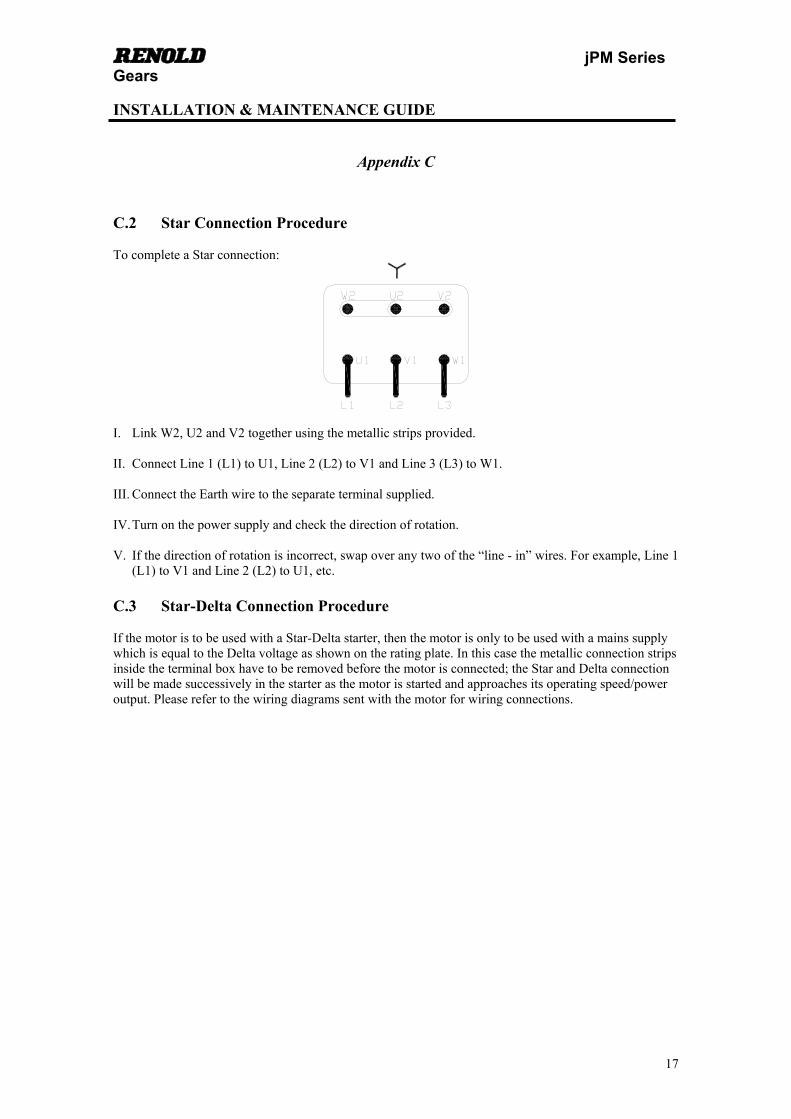
C.2 Star Connection Procedure To complete a Star connection:
I. Link W2, U2 and V2 together using the metallic strips provided. II. Connect Line 1 (L1) to U1, Line 2 (L2) to V1 and Line 3 (L3) to W1. III. Connect the Earth wire to the separate terminal supplied. IV. Turn on the power supply and check the direction of rotation. V. If the direction of rotation is incorrect, swap over any two of the “line - in” wires. For example, Line 1
(L1) to V1 and Line 2 (L2) to U1, etc. C.3 Star-Delta Connection Procedure If the motor is to be used with a Star-Delta starter, then the motor is only to be used with a mains supply which is equal to the Delta voltage as shown on the rating plate. In this case the metallic connection strips inside the terminal box have to be removed before the motor is connected; the Star and Delta connection will be made successively in the starter as the motor is started and approaches its operating speed/power output. Please refer to the wiring diagrams sent with the motor for wiring connections.

def jPM Series Gears INSTALLATION & MAINTENANCE GUIDE
18
Appendix D
UNIT ALIGNMENT When coupling the gear unit to a mating shaft, the coupling halves should be correctly aligned to ensure optimum life and performance. The irregularities which can occur in the coupling process fall into one of two categories:- Angularity, i.e. the coupling faces do not run parallel to each other (Fig. 1) Eccentricity, i.e. the coupling halves do not run concentric to each other (Fig. 2) A combination of both defects is also possible.
Fig.1 Fig.2 When correcting any defects in coupling alignment, the errors of angularity should be checked and rectified before correcting any errors of eccentricity. D.1 Angularity Errors Angularity errors should be checked for in the following manner. I. Obtain a slip block which is marginally smaller than the gap between the two coupling halves. Mark a
datum point on both coupling halves. II. Position the datum mark in Position A as shown on the diagram below. By using feeler gauges and the
slip block, measure and record the gap between the two coupling halves at Position A. III. Rotate the coupling until the datum mark is in Position B. Again, measure and record the gap, but this
time at Position B. IV. The difference between the two values will give the error in alignment in the vertical plane measured
over a length of shaft equal to the outside diameter of the coupling. This value can be used to calculate the correction in height that the connected motor or machine requires to eliminate the error.
V. Repeat the process for each side of the coupling (Positions C & D). Similarly, the difference between
the values will give an error in alignment in the horizontal plane, and can be corrected accordingly.

def jPM Series Gears INSTALLATION & MAINTENANCE GUIDE
19
Appendix D D.2 Eccentricity Errors Eccentricity errors should be checked for in the following manner. I. Obtain a Dial Test Indicator (D.T.I) and a rigid clamp. Attach this to one of the coupling halves. II. Place the D.T.I. in such a position that a sufficient `touch’ is achieved on the second coupling half. III. Move the plunger into Position A, and adjust the indicator to read zero. IV. Rotate the coupling half which is carrying the D.T.I. until Position B is reached. Observe and record
the fluctuation in dial reading. The amount of vertical correction required is equal to the difference in readings.
V. Repeat the process for Positions C & D. Similarly, this will give the horizontal alignment errors, and
can be corrected accordingly.
Note: After alignment is completed, the unit should be allowed to run until normal operating temperature has been reached. The unit should then be stopped and the alignment re-checked and corrected if necessary.

def jPM Series Gears INSTALLATION & MAINTENANCE GUIDE
20
Appendix E The correct choice of oil and grade is essential to obtain the best performance and life from the gear unit. Using too heavy a grade than required will result in reduced efficiency; whilst using too light a grade of oil will result in premature wear. If in doubt, ask Renold Gears Technical Department. If the gear unit is operating below the catalogue rating at a temperature below 60oC, then a light grade oil should be used. Medium grade oils should be used when operating up to the catalogue rating with temperatures up to 100oC. Heavy grade oils should be used at temperatures in excess of 100oC under heavy loading. However, if the unit is operating at gear rubbing speeds below 2.5 metres/sec (500 ft/min), then the next higher grade should be used than that which would normally be selected. If required, a list of recommended food grade oils is available on request. E.1 RECOMMENDED LUBRICANTS Polyalphaolefin Synthetic Oils Lubricant Light Medium Heavy
Grade Temp Deg.C Grade
Temp Deg.C Grade Temp Deg.C
Mobil Gear SHC 630 -42 to 160 632 -42 to 160 634 -39 to 160 Castrol Alpha T 220 -36 to 80 320 -33 to 80 460 -33 to 80 Shell Omala RL 220 -40 to 80 320 -40 to 90 460 -4 to 80 Esso Teresso SHP 220 -42 to 150 320 -36 to 150 460 -30 to 150

def jPM Series Gears INSTALLATION & MAINTENANCE GUIDE
21

def jPM Series Gears INSTALLATION & MAINTENANCE GUIDE
22
def jPM Series Gears INSTALLATION & MAINTENANCE GUIDE
23
IMPORTANT INFORMATION YOU MUST READ Product Safety Information of def Gear Products
Important Notes Always isolate the power source from the drive or the equipment. Always wear protective clothing, safety glasses, hats, gloves, ear protectors and safety shoes as warranted by the circumstances. Always ensure tools are in good working condition and use as directed by the manufacturer. Loosen all tension devices. Ensure that the correct lubrication is used prior to commissioning. Customers are reminded that when purchasing any technical product for use at work (or otherwise), any additional or up-to-date information and guidance, which it has not been possible to include in the publication, should be obtained from your local sales office in relation to the suitability and the safety and proper use of the product. All relevant information and guidance must be passed on by you to the person engaged in, or likely to be affected by or responsible for the use of the product. Potential Hazards There are a number of hazards that must be avoided when installing, maintaining and repairing Renold Gear units. The following are suggested safety guides when undertaking any of the above. Hot surfaces and lubricants. After prolonged running, a gear unit can generate high temperatures and can create surface temperatures that could burn the skin. Do not drain the oil from a gear unit that has been run for a prolonged period because the oil will be hot and could burn the skin. Allow the oil to cool, prior to draining. Fire and Explosions. A gear unit creates an oil mist or vapour internally after prolonged running and can be a fire and explosion risk if a naked flame is in close proximity. Allow the unit to cool prior to opening the unit. Flames or high running temperatures can burn or melt rubber compounds and melt plastic compounds and produce dangerous fumes. These compounds should be avoided until cool and then handled with protective gloves. Guards All rotating parts must be guarded with suitable guards, secured to the gear unit or machine frame. Lifting Lifting lugs or lifting points to suit eyebolts are provided on all Renold gear units. These must be used at all times. Noise Gear units run at high speed can create noise levels damaging to hearing. Ear protectors should be worn if there is a possibility of prolonged exposure to these conditions. Lubrication. The Installation & Maintenance Guide include the various types and quantities/ types of oils to be used in Renold gear units. These must be followed at all times. Electrical Equipment Follow all associated manufacturers instructions and always isolate all electrical equipment prior to carrying out any work. Holdback/ Backstops Failure of a backstop when fitted to the gear unit could result in personnel injury and machine damage. Secondary back-up systems must be provided. Installation Maintenance and Storage. Full Installation & Maintenance instructions are included in this document. Failure to follow the instructions could result in failure of the gear unit and / or damage to the equipment onto which it is being installed. General Short and long term storage instructions have been in included in this Installation & Maintenance Guide. All information contained in this document is subject to change without notice. The right is reserved to make modifications to the product to meet manufacturing conditions and/or developments (for example in design or materials) Copyright Renold Power Transmission Limited 2002. All rights reserved. Nothing containing in this publication shall constitute a part of any contract, express or implied. � RENOLD GEARS TEL + 44 [0] 1706 751000 HOLROYD GEAR WORKS FAX + 44 [0] 1706 751001 MILNROW eMAIL ; [email protected] ROCHDALE OL16 3LS ENGLAND WEB ; www.renold.com

def jPM Series Gears INSTALLATION & MAINTENANCE GUIDE
24
WORLDWIDE SALES AND SERVICES
RENOLD Gears Holroyd Gear Works
Station Road Milnrow
Rochdale Lancashire, OL16 3LS
England
TEL: +44 (0) 1706 751000
FFAX: +44 (0) 1706 751001 EMAIL: [email protected] WEB: www.renold.com
AUSTRALIA Renold Australia Proprietary Ltd TEL: +61 (0) 3 9262 3333 FAX: +61 (0) 3 9561 8561 EMAIL: [email protected] AUSTRIA Renold GmbH TEL: +43 (0) 1 3303484 0 FAX: +43 (0) 1 3303484 5 BELGIUM Renold Continental Ltd. TEL: +32 (0) 2 2011262 FAX: +32 (0) 2 2032210 EMAIL: [email protected] CANADA Renold Canada Ltd. TOLL FREE: 1-800-265-9970 TEL: +1 519 756 6118 FAX: +1 519 756 1767 EMAIL: [email protected] CHINA Renold Transmission TEL: +86 21 5046 2696 FAX: +86 21 5046 2695 EMAIL: [email protected] CZECH REPUBLIC Renold GmbH TEL: +420/ 606 727 811 FAX: +420/ 577 240 324 DENMARK Renold A/S TEL: +45 43 452611 FAX: +45 43 456592 EMAIL: [email protected]
FRANCEBrampton Renold TEL: +33 (0) 320 16 29 29 FAX: +33 (0) 320 16 29 00 GERMANY Renold Getriebe & Kupplungen TEL: +49 (0) 2256 959074 FAX: +49 (0) 2256 959169 EMAIL: [email protected] HOLLAND Renold Continental Ltd. TEL: +31 (0) 20 614 6661 FAX: +31 (0) 20 614 6391 EMAIL: [email protected] HUNGARY Renold GmbH TEL: +36 1 287 8086 FAX: +36 1 287 8087 KOREA S.S. Corporation TEL: 00-822-783-6829 FAX: 00-822-784-9322 EMAIL: [email protected] MALAYSIA Renold (Malaysia) TEL: +603-5122 7880 FAX: +603-5122 7881 EMAIL: [email protected]
NEW ZEALAND Renold New Zealand TEL: +64 (0) 9 828 5018 FAX: +64 (0) 9 828 5019 EMAIL: [email protected] SINGAPORE Renold Transmission Ltd. TEL: +65 6760 2422 FAX: +65 6760 1507 EMAIL: [email protected] SOUTH AFRICA Renold Croft (Pty) Ltd. TEL: +27 11 747 9500 FAX: +27 11 747 9505 EMAIL: [email protected] SWEDEN Renold Transmission AB TEL: +45 43 45 26 11 FAX: +45 43 45 65 92 EMAIL: [email protected] SWITZERLAND Renold (Switzerland) GmbH TEL: +41 (0) 1 824 8484 FAX: +41 (0) 1 824 8411 EMAIL: [email protected] USA Renold Inc TEL: +1 716 326 3121 FAX: +1 716 326 6121 EMAIL: [email protected]