Embed Size (px)
Citation preview
20075018
211 Virtual Car and Motorcycle Aerodynamics*
Norbert GRUEN 1) , Rainer DEMUTH 2) , Gerhard HOFER 3) , Hans KERSCHBAUM 4)
This paper describes the status of CFD usage in the aerodynamic development of passenger cars and motorcycles at the BMW Group. After an explanation of the significance and time frame of aerodynamics in the overall development process the questions are discussed which can be addressed via simulation today. Considering the simulation process it gets clear that the bottleneck is the effort needed to prepare the geometry. For this reason the primary tool at BMW is a Lattice-Boltzmann code which allows the easy handling of complex configurations. The achievable accuracy to date is sufficient for a productive use and is shown on selected examples. Finally some practical applications demonstrate the benefit of simulation for the aerodynamicist.
Keywords: Aerodynamics, Development Process, Simulation, CFD, Lattice-Boltzmann
1. INTRODUCTION
Due to the level of maturity that simulation methods have reached today, CFD tools are more and more employed in a productive manner in the aerodynamic development process. The objective is twofold. First one tries to reduce the number of cost and time intensive experiments in the early phase and on the other hand CFD enables a deeper understanding of the flow phenomena around and through detailed vehicle models in the later phase. This paper presents the progress of CFD usage during the aerodynamic development of passenger cars and motorcycles at the BMW Group since a previous presentation at JSAE 2001 [1]. First an overview is given of the development process and the questions that can be tackled by simulation in the different phases. Then the simulation process is explained from geometry preparation to results analysis. Some selected validation cases demonstrate the accuracy that can be achieved at the moment. Finally a number of practical examples is used to show the capabilities for in detail analysis of the flow field and the benefit for the aerodynamicist.
2. AERODYNAMICS IN THE OVERALL DEVELOPMENT PROCESS
Aerodynamics is one of the few disciplines to get involved in vehicle development at the very beginning. In the course of the overall development process more and more details of the vehicle become available and accordingly the questions become more detailed (Fig.1).
Already in the initial phase the first styling ideas have to be assessed with respect to the impact of proportions on aerodynamic forces and driving stability. At this point only virtual models exist and hence simulation is the tool of choice. At the transition to the concept phase simplified underhood and underbody details are included, often taken from the predecessor. This allows to address thermal management questions as well. However, the investigation of soiling and snow deposition has to wait until roadworthy prototypes are available for physical testing. CFD tools are not yet sophisticated enough to be applied to these problems in depth.
Fig.1: Aerodynamic Questions and Tools [2] No matter whether simulation or physical testing is employed [3], the time frame for aerodynamics in the overall development process is quite short and requires efficient approaches to have an impact on the product. Simulation is almost the only way to identify problems early enough to avoid cost and time intensive measures if detected in later phases.
____________________________________________________*Presented at 2007 JSAE Annual Congress. 1), 2), 3), 4) BMW Group, Center for Innovation and R&D,Knorrstr. 147, D-80788 Muenchen, Germany
20075018
3. SIMULATION PROCESS
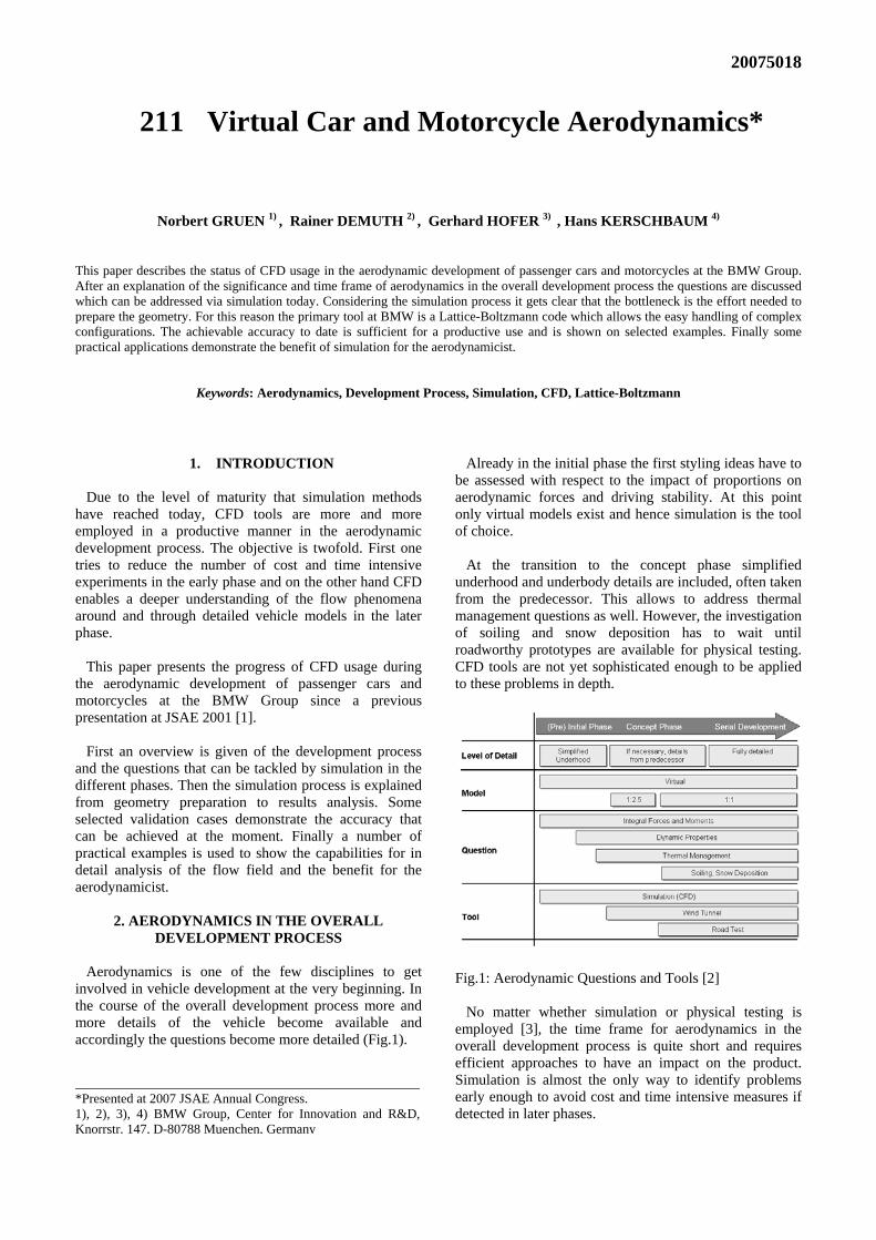
Regardless of the particular tool, each CAE simulation process starts with the collection of geometry input data. In case of aerodynamics we distinguish between the exterior skin, created by the stylist either virtually or in clay, and the underhood and underbody components (Fig.2). Preparing the geometry as input for the CFD tool means to create a facetized representation of the individual components. For the Lattice-Boltzmann code (PowerFLOW, [4]) used at BMW it is not necessary to generate a single connected surface mesh. The entire configuration is composed of any number of individual solids and/or zero-thickness shells which may intersect each other.
Fig.2: Simulation Process Another advantage of the tool is the automatic creation of the fluid mesh which is a lattice of rectangular cells as depicted in Fig.3.
Fig.3: Detailed Motorcycle Model in the Lattice
Their intersection with the geometry is discretized automatically as part of the simulation. The user just defines the resolution level by simple geometries or offsets for the near surface layers. Together with the efficient parallelization of the code a total turnaround from the start of the geometry preparation to first results of two days to two weeks is possible, depending on the complexity and quality of the geometry data. The simulation itself always runs in transient mode. If available, initial conditions from a similar case can be used to shorten the time needed to reach a settled quasi steady-state. For external aerodynamics the typical monitoring quantities are drag and lift to decide when to stop the simulation and which period should be used to obtain time-averaged results (Fig. 4).
Fig.4: History of Transient Forces
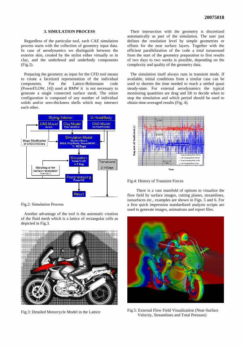
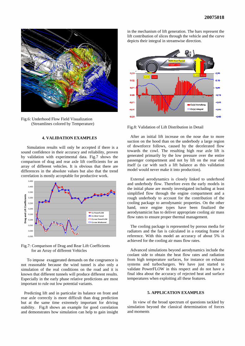
There is a vast manifold of options to visualize the flow field by surface images, cutting planes, streamlines, isosurfaces etc., examples are shown in Figs. 5 and 6. For a first quick impression standardized analysis scripts are used to generate images, animations and report files.
Fig.5: External Flow Field Visualization (Near-Surface Velocity, Streamlines and Total Pressure)
20075018
Fig.6: Underhood Flow Field Visualization (Streamlines colored by Temperature)
4. VALIDATION EXAMPLES
Simulation results will only be accepted if there is a sound confidence in their accuracy and reliability, proven by validation with experimental data. Fig.7 shows the comparison of drag and rear axle lift coefficients for an array of different vehicles. It is obvious that there are differences in the absolute values but also that the trend correlation is mostly acceptable for productive work.
-0,050
0,000
0,050
0,100
0,150
0,200
0,250
0,300
0,350
0,400
0,450
Dra
g an
d Li
ft C
oeffi
cien
ts
Cx PowerFLOW
Cx Wind Tunnel
Cz-rear PowerFLOW
Cz-rear Windtunnel
Fig.7: Comparison of Drag and Rear Lift Coefficients for an Array of different Vehicles
To impose exaggerated demands on the congruence is not reasonable because the wind tunnel is also only a simulation of the real conditions on the road and it is known that different tunnels will produce different results. Especially in the early phase relative predictions are most important to rule out low potential variants.
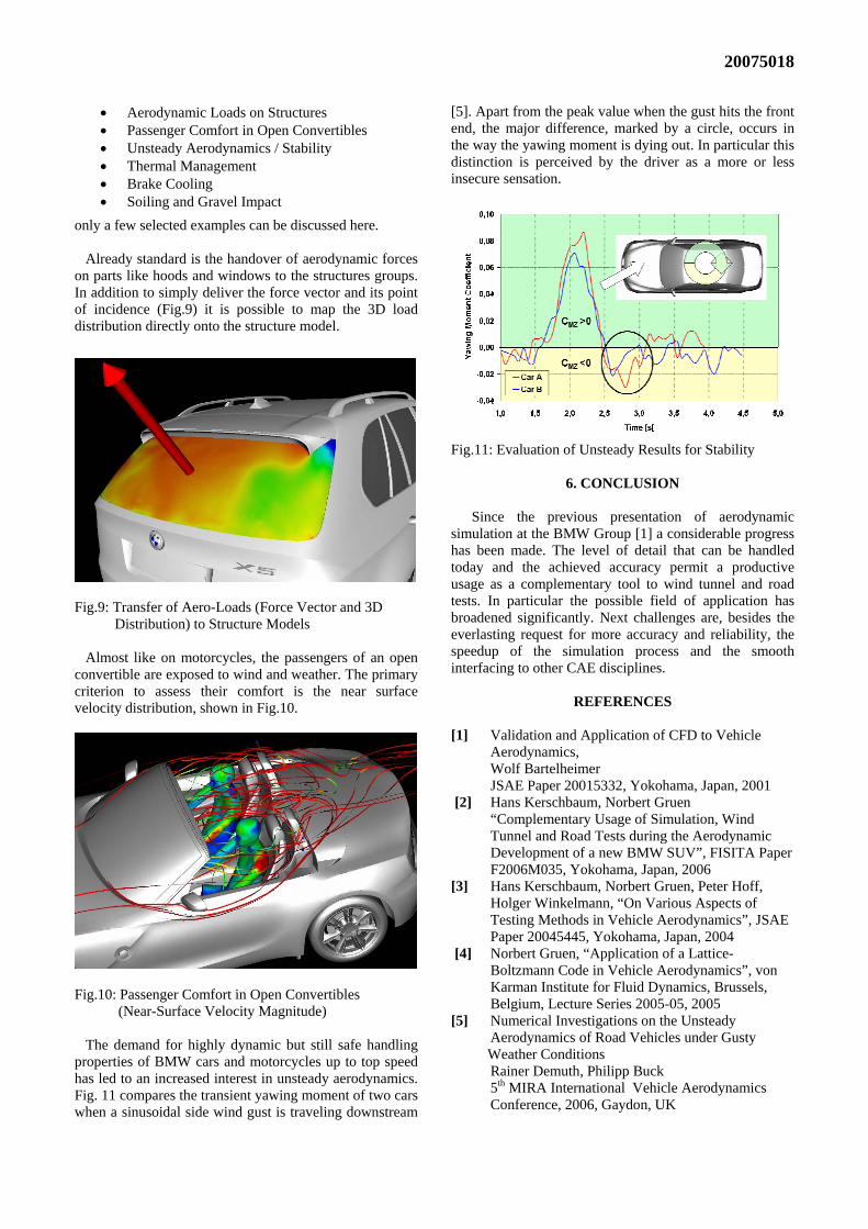
Predicting lift and in particular its balance on front and rear axle correctly is more difficult than drag prediction but at the same time extremely important for driving stability. Fig.8 shows an example for good correlation and demonstrates how simulation can help to gain insight
in the mechanism of lift generation. The bars represent the lift contribution of slices through the vehicle and the curve depicts their integral in streamwise direction.
Fig.8: Validation of Lift Distribution in Detail After an initial lift increase on the nose due to more suction on the hood than on the underbody a large region of downforce follows, caused by the decelerated flow towards the cowl. The resulting high rear axle lift is generated primarily by the low pressure over the entire passenger compartment and not by lift on the rear end itself (a car with such a lift balance as this validation model would never make it into production). External aerodynamics is closely linked to underhood and underbody flow. Therefore even the early models in the initial phase are mostly investigated including at least simplified flow through the engine compartment and a rough underbody to account for the contribution of the cooling package to aerodynamic properties. On the other hand, once engine types have been finalized the aerodynamicist has to deliver appropriate cooling air mass flow rates to ensure proper thermal management. The cooling package is represented by porous media for radiators and the fan is calculated in a rotating frame of reference. With this model an accuracy of about 5% is achieved for the cooling air mass flow rates. Advanced simulations beyond aerodynamics include the coolant side to obtain the heat flow rates and radiation from high temperature surfaces, for instance on exhaust systems and turbochargers. We have just started to validate PowerFLOW in this respect and do not have a final idea about the accuracy of rejected heat and surface temperatures when exploiting all these features.
5. APPLICATION EXAMPLES
In view of the broad spectrum of questions tackled by simulation beyond the classical determination of forces and moments
20075018
• Aerodynamic Loads on Structures • Passenger Comfort in Open Convertibles • Unsteady Aerodynamics / Stability • Thermal Management • Brake Cooling • Soiling and Gravel Impact
only a few selected examples can be discussed here. Already standard is the handover of aerodynamic forces on parts like hoods and windows to the structures groups. In addition to simply deliver the force vector and its point of incidence (Fig.9) it is possible to map the 3D load distribution directly onto the structure model.
Fig.9: Transfer of Aero-Loads (Force Vector and 3D Distribution) to Structure Models Almost like on motorcycles, the passengers of an open convertible are exposed to wind and weather. The primary criterion to assess their comfort is the near surface velocity distribution, shown in Fig.10.
Fig.10: Passenger Comfort in Open Convertibles (Near-Surface Velocity Magnitude) The demand for highly dynamic but still safe handling properties of BMW cars and motorcycles up to top speed has led to an increased interest in unsteady aerodynamics. Fig. 11 compares the transient yawing moment of two cars when a sinusoidal side wind gust is traveling downstream
[5]. Apart from the peak value when the gust hits the front end, the major difference, marked by a circle, occurs in the way the yawing moment is dying out. In particular this distinction is perceived by the driver as a more or less insecure sensation.
Fig.11: Evaluation of Unsteady Results for Stability
6. CONCLUSION
Since the previous presentation of aerodynamic simulation at the BMW Group [1] a considerable progress has been made. The level of detail that can be handled today and the achieved accuracy permit a productive usage as a complementary tool to wind tunnel and road tests. In particular the possible field of application has broadened significantly. Next challenges are, besides the everlasting request for more accuracy and reliability, the speedup of the simulation process and the smooth interfacing to other CAE disciplines.
REFERENCES
[1] Validation and Application of CFD to Vehicle
Aerodynamics, Wolf Bartelheimer JSAE Paper 20015332, Yokohama, Japan, 2001 [2] Hans Kerschbaum, Norbert Gruen
“Complementary Usage of Simulation, Wind Tunnel and Road Tests during the Aerodynamic Development of a new BMW SUV”, FISITA Paper F2006M035, Yokohama, Japan, 2006
[3] Hans Kerschbaum, Norbert Gruen, Peter Hoff, Holger Winkelmann, “On Various Aspects of Testing Methods in Vehicle Aerodynamics”, JSAE Paper 20045445, Yokohama, Japan, 2004
[4] Norbert Gruen, “Application of a Lattice-Boltzmann Code in Vehicle Aerodynamics”, von Karman Institute for Fluid Dynamics, Brussels, Belgium, Lecture Series 2005-05, 2005
[5] Numerical Investigations on the Unsteady Aerodynamics of Road Vehicles under Gusty Weather Conditions Rainer Demuth, Philipp Buck
5th MIRA International Vehicle Aerodynamics Conference, 2006, Gaydon, UK