Embed Size (px)
Citation preview
Jacton Electromechanical Co.,Ltd http://www.screw-jack.com 1
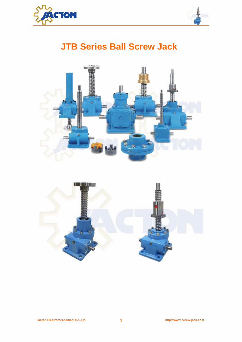
JTB Series Ball Screw Jack
Jacton Electromechanical Co.,Ltd http://www.screw-jack.com 2
Contents
General Information --------------------------------------------------------------------------- 3 Configurations----------------------------------------------------------------------------------- 4 Specifications------------------------------------------------------------------------------------ 5 Selection Guides
1. Jack Series ---------------------------------------------------------------------------------------- 6
2. Load Capacity ------------------------------------------------------------------------------------- 6
3. Screw Configurations & Mounting Orientation -------------------------------------------------- 6
4. Travel Stroke--------------------------------------------------------------------------------------- 6
5. Gear Ratio ----------------------------------------------------------------------------------------- 7
6. Screw End Fittings--------------------------------------------------------------------------------- 7
7. Worm Shaft Input Type---------------------------------------------------------------------------- 7
8. Accessories ---------------------------------------------------------------------------------------- 8
Type Selection
1. Determination of Screw Jack Type --------------------------------------------------------------- 9
2. Verification Of Input Power------------------------------------------------------------------------ 9
3. Verification Of The Ball Screw Stability ---------------------------------------------------------- 10
4. Permissible Radial Force ------------------------------------------------------------------------- 11
Dimensions
1. Model JTB5 (Tr16x5)------------------------------------------------------------------------------ 12-13
2. Model JTB10 (Tr20x5) ---------------------------------------------------------------------------- 14-15
3. Model JTB25 (Tr25x8) ---------------------------------------------------------------------------- 16-17
4. Model JTB50 (Tr40x10) --------------------------------------------------------------------------- 18-19
5. Model JTB100 (Tr50x12) -------------------------------------------------------------------------- 20-21
6. Model JTB150 (Tr55x12) ----------------------------------------- -------------------------------- 22-23
7. Model JTB200 (Tr65x12) --------------------------- ---------------------------------------------- 24-25
8. Model JTB300 (Tr80x16) ---------------------------- --------------------------------------------- 26-27
9. Model JTB500 (Tr100x20) ------------------------------------- ----------------------------------- 28-29
Ball Screw Jack System ---------------------------------------- ------------------------------ 30 Application Examples -------------------------------------- ----------------------------------- 31 Operation Manual ------------------------------------------------- ------------------------------ 32-36
Frequently Asked Questions ---------------------------------------------------------------- 37-40 Company History -------------------------------------------------------------------------------- 41 Contact Us ----------------------------------------------------------------------------------------- 42
Jacton Electromechanical Co.,Ltd http://www.screw-jack.com 3
11
General Information
* Models JTB5, JTB10, JTB25, JTB50, JTB100, JTB150, JTB200, JTB300, JTB500
* Lift force from 5kN to 500kN, customized 750kN, 1000kN ball screw jack
* high accuracy ball screw without self-locking, high efficiency, long service life, uniform lifting speed
* Translating screw, anti-rotation keyed screw and rotating screw configurations
* Upright mounting, inverted mounting, double clevis pivot mounting
* Top plate, threaded end, clevis end and plain end fittings
* Hand operated, electric driven or both
* Individual or multiple screw jack system arrangements
* Each jack has two worm gear ratios, high speed, low speed
* No standard travel length, all screw jack stroke produced following your needs
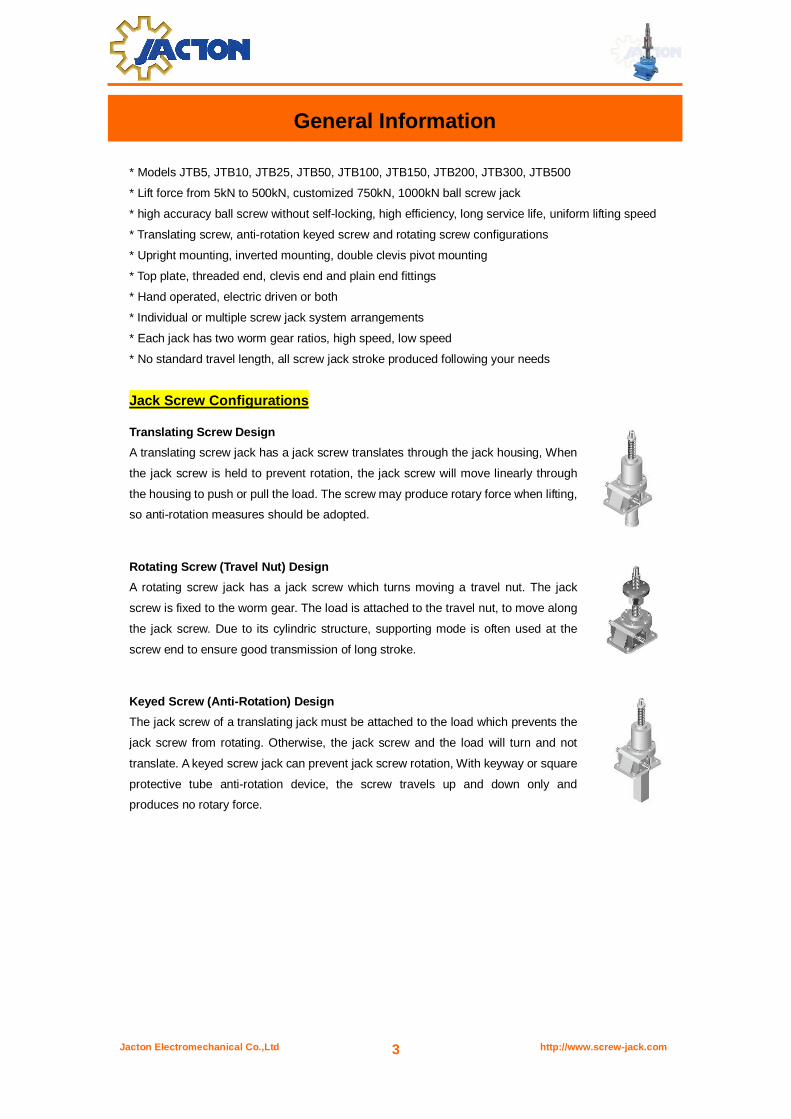
Jack Screw Configurations
Translating Screw Design
A translating screw jack has a jack screw translates through the jack housing, When
the jack screw is held to prevent rotation, the jack screw will move linearly through
the housing to push or pull the load. The screw may produce rotary force when lifting,
so anti-rotation measures should be adopted.
Rotating Screw (Travel Nut) Design
A rotating screw jack has a jack screw which turns moving a travel nut. The jack
screw is fixed to the worm gear. The load is attached to the travel nut, to move along
the jack screw. Due to its cylindric structure, supporting mode is often used at the
screw end to ensure good transmission of long stroke.
Keyed Screw (Anti-Rotation) Design
The jack screw of a translating jack must be attached to the load which prevents the
jack screw from rotating. Otherwise, the jack screw and the load will turn and not
translate. A keyed screw jack can prevent jack screw rotation, With keyway or square
protective tube anti-rotation device, the screw travels up and down only and
produces no rotary force.

Jacton Electromechanical Co.,Ltd http://www.screw-jack.com 4
Configurations
High Accuracy Ball Screw
1. Heavy load grinding ball screw shaft, hardness HRC58-62
2. High efficiency, high performance, high accuracy grade C6 or C7, low backlash, long service life
Tapered Roller Bearing
1. Preloaded for reduced assembly spring rate and high thrust load
2. Provides excellent support for side loading and horizontal applications
3. Maintains exact gear alignment under separating and thrust forces
4. Bearing sized for endurance and maximum loading conditions
Bronze Worm Gear
1. Precison hobbing machine for processing
2. Bronze material, high hardness, excellent wear resistance
Worm Shaft
1. Worm rotary cutting processing machine and grinding machine processing, high precision
2. High frequency heat treatment of worm, 40Cr or C45 steel material, high hardness, customized
stainless steel worm
Rugged Housing
1. CNC precision automatic lathe processing
2. Cast iron or ductile cast iron material, customized aluminum, alloy steel material
Grease Seals
1. Double lip oil seal, prevent grease or gear oil leak

Jacton Electromechanical Co.,Ltd http://www.screw-jack.com 5
Specifications

Jacton Electromechanical Co.,Ltd http://www.screw-jack.com 6
JTB - 100 - UR - 300 - H - II - C - HW
1 2 3 4 5 6 7 8
Selection Guides
1. Jack Series JT: “Jacton” brand
B: B series ball screw jack
2. Load Capacity Model 5 10 25 50 100 150 200 300 500
Load capacity(kN) 4.9 9.8 24.5 49 98 147 196 294 490
Before selecting above model, please check the corresponding specificiations
3. Screw Configuration & Mounting Orientation US: Upright translating screw UK: Upright keyed translating screw UR: Upright rotating screw
IS: Inverted translating screw IK: Inverted keyed translating screw IR: Inverted rotating screw
4. Travel Stroke 300, means travel stroke 300mm
No standard travel stroke, all screw jack stroke produced following your needs
Jacton Electromechanical Co.,Ltd http://www.screw-jack.com 7
5. Gear Ratio
Each JTB ball screw jack model has two gear ratios.
Model 5 10 25 50 100 150 200 300 500
H: high gear ratio 1/5 1/5 1/6 1/6 1/8 1/8 1/8 10 2/3 10 2/3
Stroke per turn of
worm shaft
1
mm
1
mm
1.33
mm
1.67
mm
1.5
mm
1.5
mm
1.5
mm
1.5
mm
1.88
mm
L: low gear ratio 1/20 1/20 1/24 1/24 1/24 1/24 1/24 1/32 1/32
Stroke per turn of
worm shaft
0.25
mm
0.25
mm
0.33
mm
0.42
mm
0.5
mm
0.5
mm
0.5
mm
0.5
mm
0.63
mm
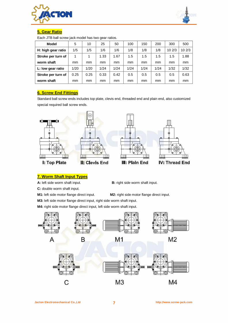
6. Screw End Fittings Standard ball screw ends includes top plate, clevis end, threaded end and plain end, also customized
special required ball screw ends.
7. Worm Shaft Input Types
A: left side worm shaft input. B: right side worm shaft input.
C: double worm shaft input.
M1: left side motor flange direct input. M2: right side motor flange direct input.
M3: left side motor flange direct input, right side worm shaft input.
M4: right side motor flange direct input, left side worm shaft input.
Jacton Electromechanical Co.,Ltd http://www.screw-jack.com 8
Example>>>>>> JT-B-100-UR-1000-L-I-C-PP/BB/HW
1. Ball Screw Type
2. 98kN
3. Upright Rotating Screw
4. 1000mm Stroke
5. Low Gear Ratio
6. Top Plate End Fitting
7. Double Worm Shaft Input
8. Protective Pipe
9. Bellows Boot
10. Hand Wheel
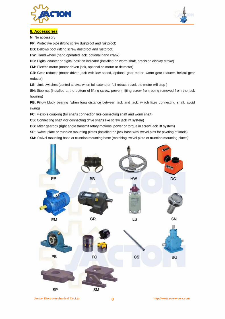
8. Accessories N: No accessory
PP: Protective pipe (lifting screw dustproof and rustproof)
BB: Bellows boot (lifting screw dustproof and rustproof)
HW: Hand wheel (hand operated jack, optional hand crank)
DC: Digital counter or digital position indicator (installed on worm shaft, precision display stroke)
EM: Electric motor (motor driven jack, optional ac motor or dc motor)
GR: Gear reducer (motor driven jack with low speed, optional gear motor, worm gear reducer, helical gear
reducer)
LS: Limit switches (control stroke, when full extend or full retract travel, the motor will stop )
SN: Stop nut (installed at the bottom of lifting screw, prevent lifting screw from being removed from the jack
housing)
PB: Pillow block bearing (when long distance between jack and jack, which fixes connecting shaft, avoid
swing)
FC: Flexible coupling (for shafts connection like connecting shaft and worm shaft)
CS: Connecting shaft (for connecting drive shafts like screw jack lift system)
BG: Miter gearbox (right angle transmit rotary motions, power or torque in screw jack lift system)
SP: Swivel plate or trunnion mounting plates (installed on jack base with swivel pins for pivoting of loads)
SM: Swivel mounting base or trunnion mounting base (matching swivel plate or trunnion mounting plates)
Jacton Electromechanical Co.,Ltd http://www.screw-jack.com 9
Type Selection
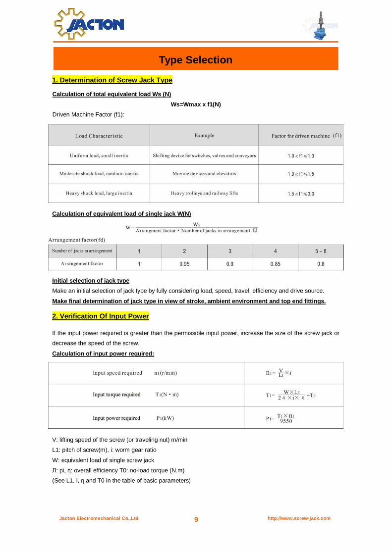
1. Determination of Screw Jack Type
Calculation of total equivalent load Ws (N)
Ws=Wmax x f1(N)
Driven Machine Factor (f1):
Calculation of equivalent load of single jack W(N)
Initial selection of jack type
Make an initial selection of jack type by fully considering load, speed, travel, efficiency and drive source.
Make final determination of jack type in view of stroke, ambient environment and top end fittings.
2. Verification Of Input Power
If the input power required is greater than the permissible input power, increase the size of the screw jack or
decrease the speed of the screw.
Calculation of input power required:
V: lifting speed of the screw (or traveling nut) m/min
L1: pitch of screw(m), i: worm gear ratio
W: equivalent load of single screw jack
Л: pi, η: overall efficiency T0: no-load torque (N.m)
(See L1, i, η and T0 in the table of basic parameters)

Jacton Electromechanical Co.,Ltd http://www.screw-jack.com 10
3. Verification Of The Screw Stability
Verify the screw stability when the axial compression load exists. If the load is greater than the critical load,
increase the sizes before calculation.
The critical load is calculated with the following formula:
Pcr: critical load, d: screw root diameter mm(see 4th page of specifications)
fm: support factor, La: distance between action points, mm
W: equivalent load of single jack(N), SF: safety factor(generally SF=4)
For verification of the screw stability, choose La(based sizes) and fm (on the support factor) as follows
A Jack fixed shaft terminal free, fm=2.5×10⁴ B Jack fixed – top plate fixed, fm=20×104
Jacton Electromechanical Co.,Ltd http://www.screw-jack.com 11
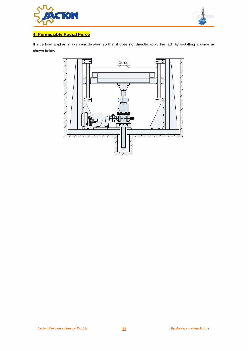
4. Permissible Radial Force
If side load applies, make consideration so that it does not directly apply the jack by installing a guide as
shown below.
Jacton Electromechanical Co.,Ltd http://www.screw-jack.com 12
Dimensions
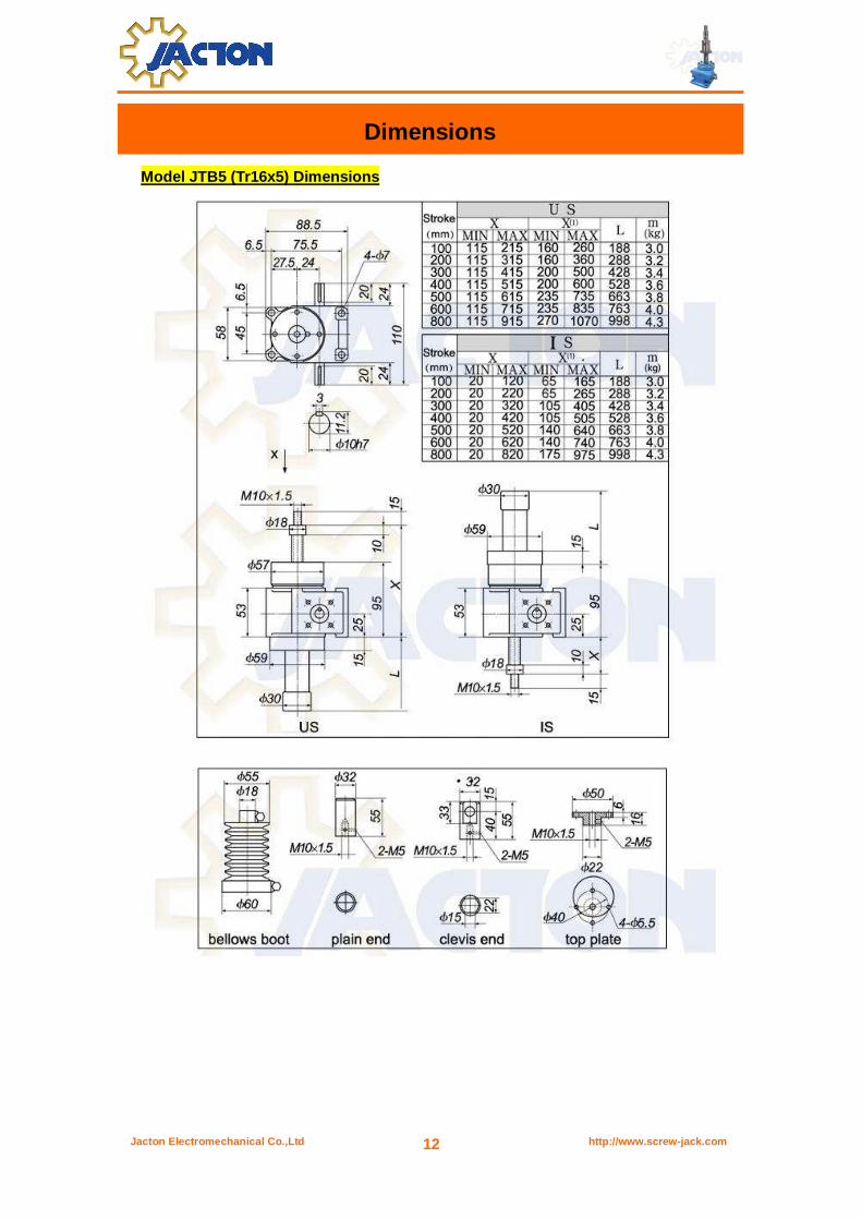
Model JTB5 (Tr16x5) Dimensions

Jacton Electromechanical Co.,Ltd http://www.screw-jack.com 13
Jacton Electromechanical Co.,Ltd http://www.screw-jack.com 14
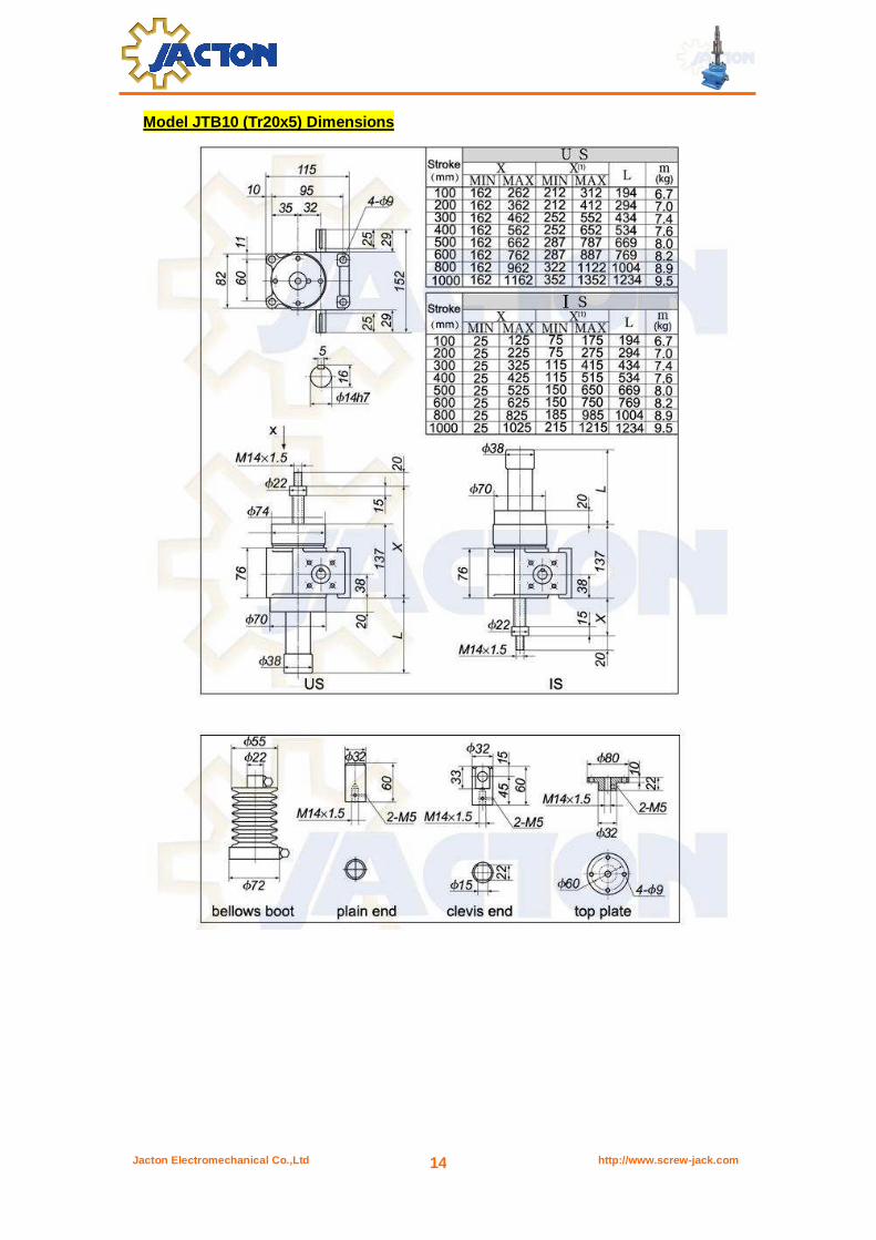
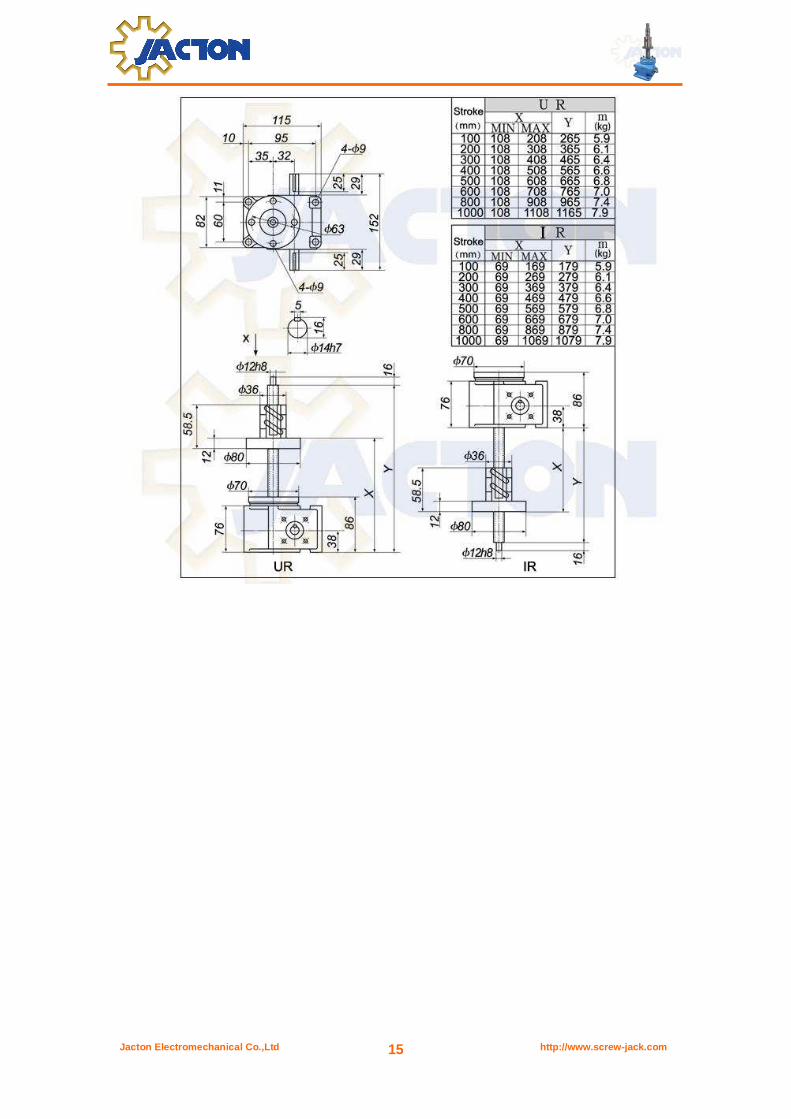
Model JTB10 (Tr20x5) Dimensions
Jacton Electromechanical Co.,Ltd http://www.screw-jack.com 15

Jacton Electromechanical Co.,Ltd http://www.screw-jack.com 16
Model JTB25 (Tr25x8) Dimensions
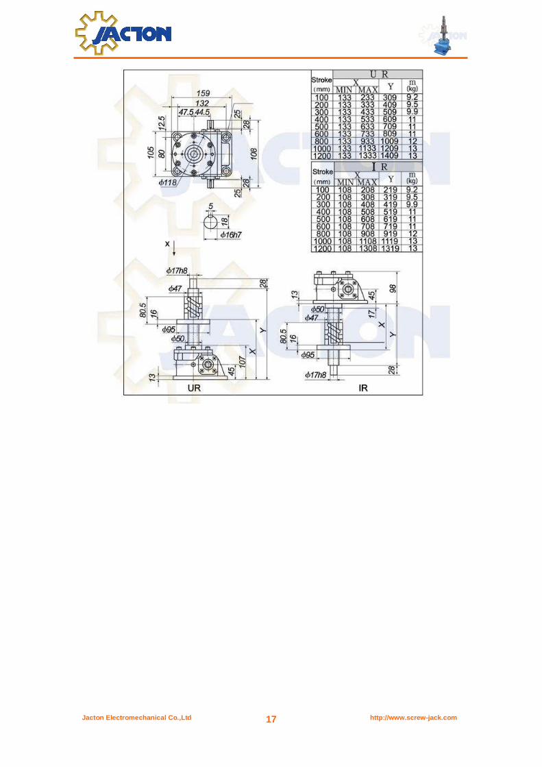
Jacton Electromechanical Co.,Ltd http://www.screw-jack.com 17
Jacton Electromechanical Co.,Ltd http://www.screw-jack.com 18
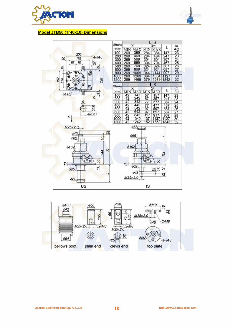
Model JTB50 (Tr40x10) Dimensions
Jacton Electromechanical Co.,Ltd http://www.screw-jack.com 19

Jacton Electromechanical Co.,Ltd http://www.screw-jack.com 20
Model JTB100 (Tr50x12) Dimensions

Jacton Electromechanical Co.,Ltd http://www.screw-jack.com 21
Jacton Electromechanical Co.,Ltd http://www.screw-jack.com 22
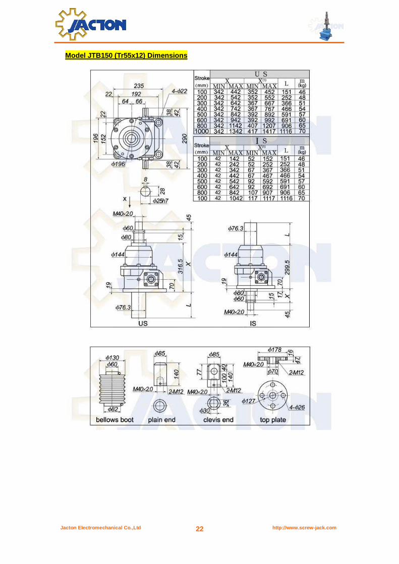
Model JTB150 (Tr55x12) Dimensions
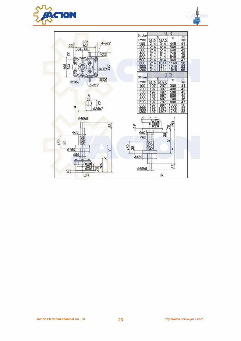
Jacton Electromechanical Co.,Ltd http://www.screw-jack.com 23
Jacton Electromechanical Co.,Ltd http://www.screw-jack.com 24
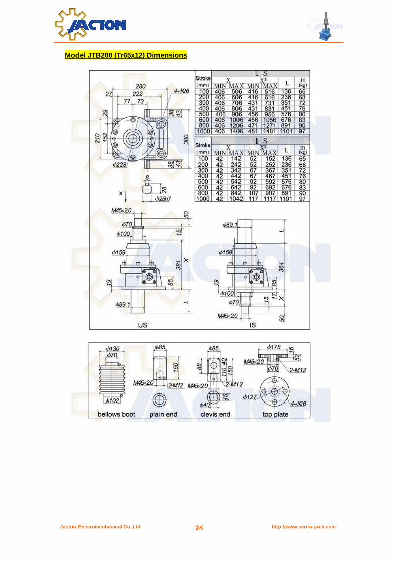
Model JTB200 (Tr65x12) Dimensions
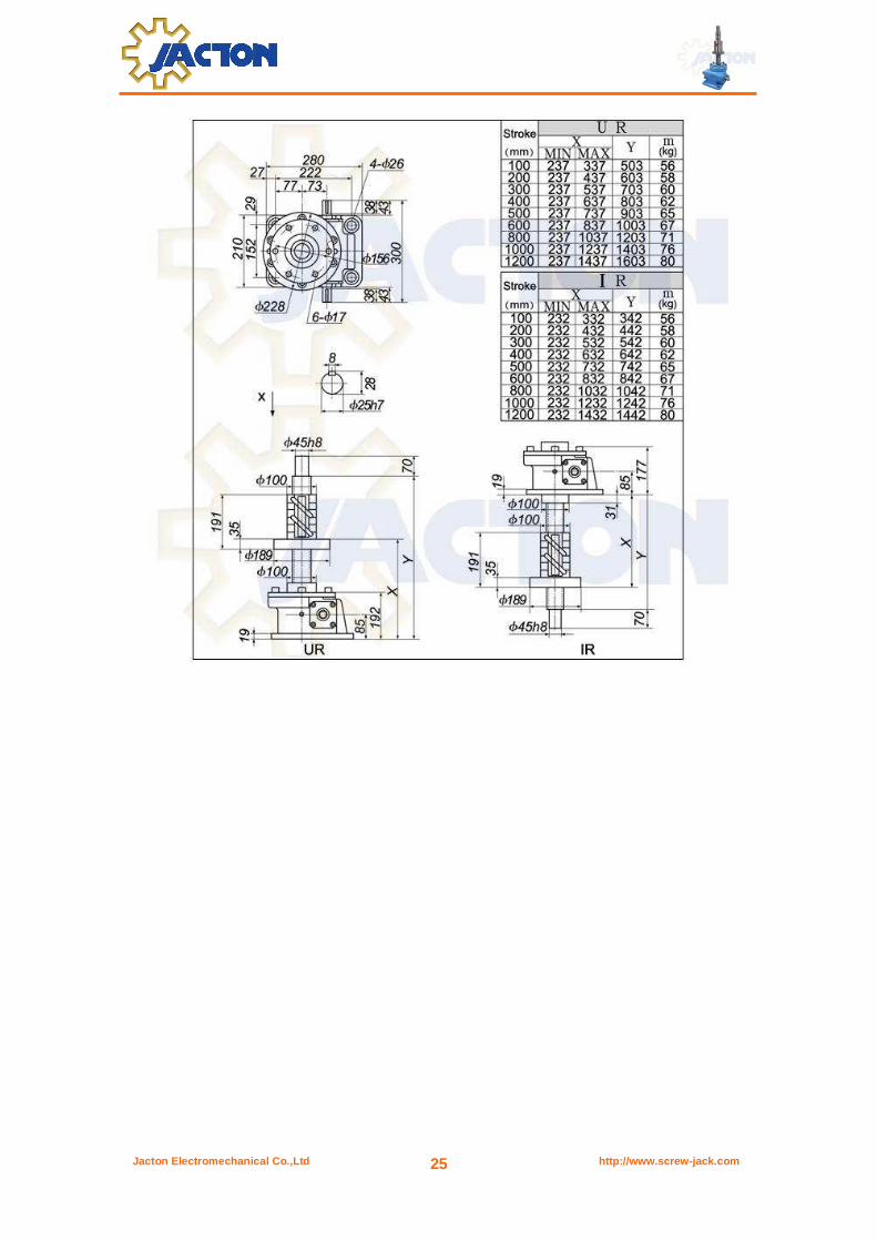
Jacton Electromechanical Co.,Ltd http://www.screw-jack.com 25

Jacton Electromechanical Co.,Ltd http://www.screw-jack.com 26
Model JTB300 (Tr80x16) Dimensions
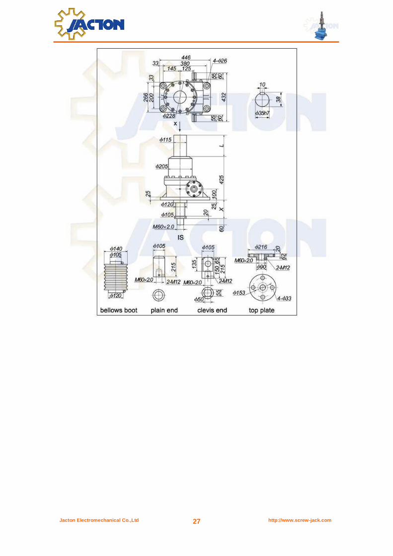
Jacton Electromechanical Co.,Ltd http://www.screw-jack.com 27
Jacton Electromechanical Co.,Ltd http://www.screw-jack.com 28
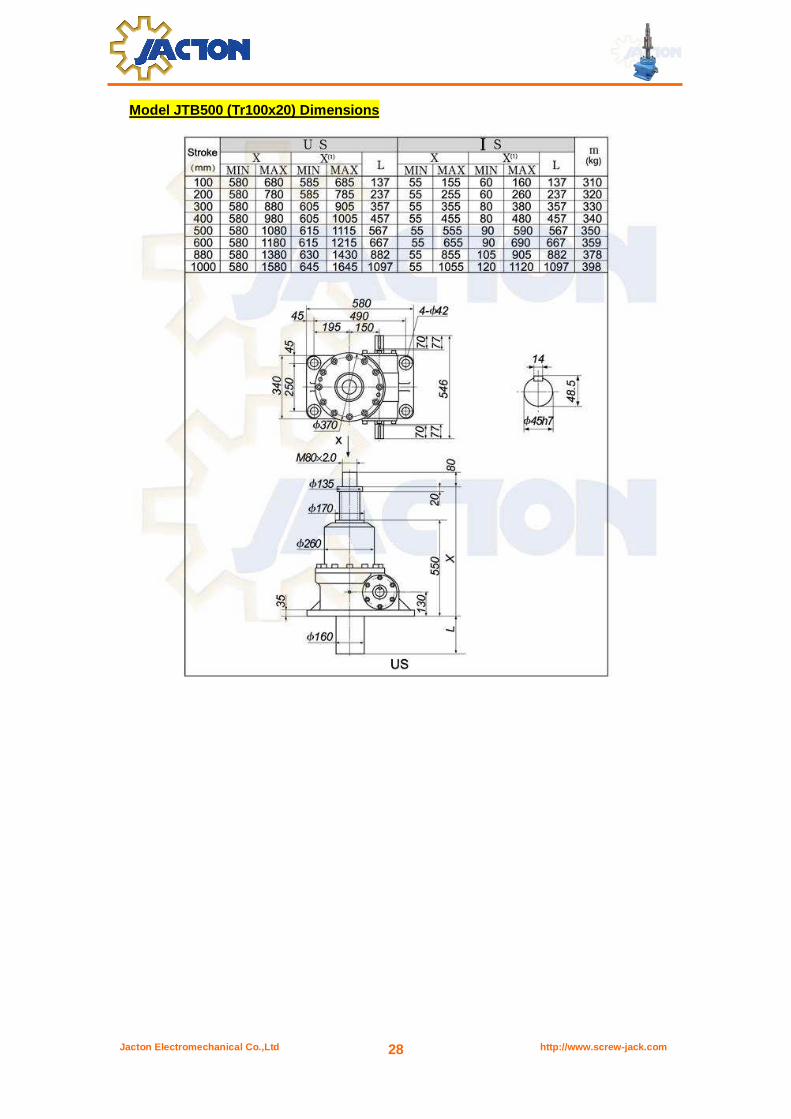
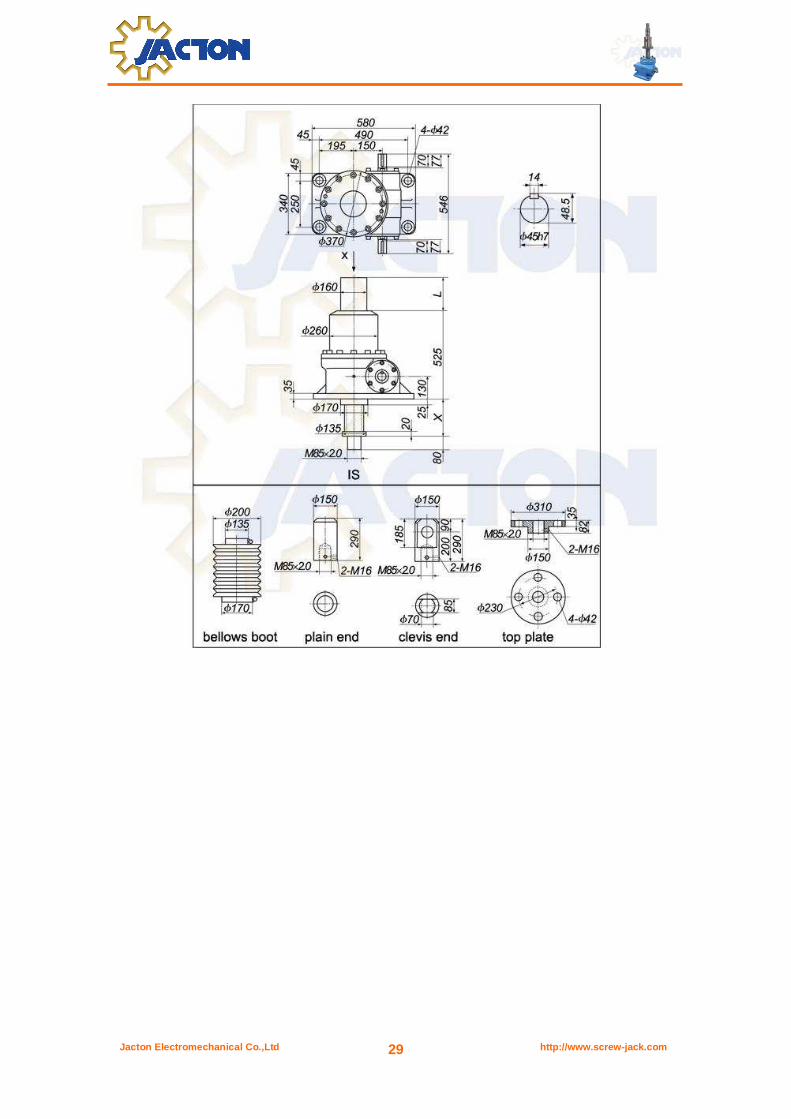
Model JTB500 (Tr100x20) Dimensions
Jacton Electromechanical Co.,Ltd http://www.screw-jack.com 29
Jacton Electromechanical Co.,Ltd http://www.screw-jack.com 30
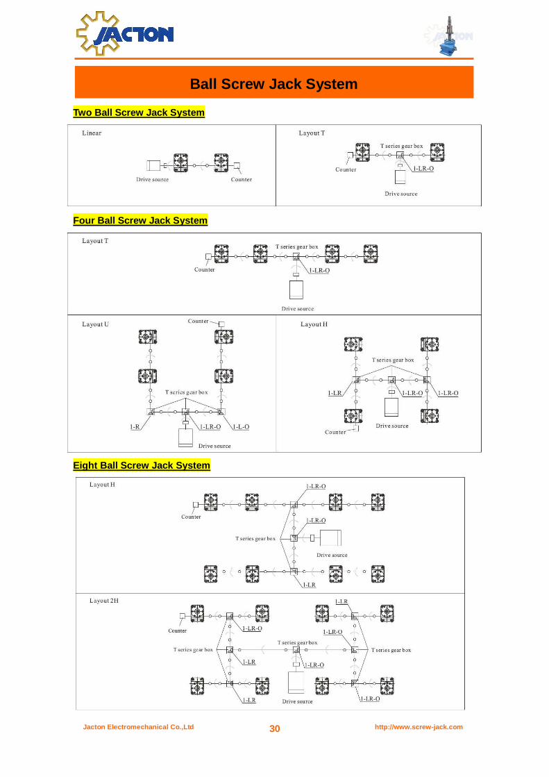
Ball Screw Jack System
Two Ball Screw Jack System
Four Ball Screw Jack System
Eight Ball Screw Jack System
Jacton Electromechanical Co.,Ltd http://www.screw-jack.com 31
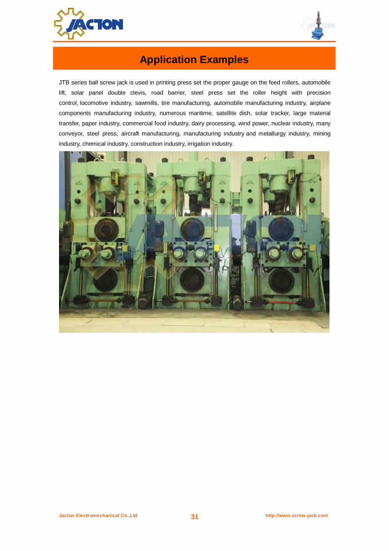
JTB series ball screw jack is used in printing press set the proper gauge on the feed rollers, automobile
lift, solar panel double clevis, road barrier, steel press set the roller height with precision
control, locomotive industry, sawmills, tire manufacturing, automobile manufacturing industry, airplane
components manufacturing industry, numerous maritime, satellite dish, solar tracker, large material
transfer, paper industry, commercial food industry, dairy processing, wind power, nuclear industry, many
conveyor, steel press, aircraft manufacturing, manufacturing industry and metallurgy industry, mining
industry, chemical industry, construction industry, irrigation industry.
Application Examples

Jacton Electromechanical Co.,Ltd http://www.screw-jack.com 32
Operation Manual
Read this manual before installation or operation of screw jack. Failure to understand this manual,
install or operate screw jack properly could result in damage to the Jack and or serious personal
injury.
Do not exceed the screw jack ratings including design load, travel, and input speed. Install, align and
shield all moving parts properly. Proper machinery installation practices should be followed. Safety
codes for mechanical power transmissions apparatus are to be followed. Check for and adhere to all
applicable safety codes. Bolts should be sized to fit the screw jack base mounting holes, at least
grade 5 and tightened to the appropriate torque. Mounting bases should be flat and sufficiently strong
to support the load on the jack. Properly lubricate and maintain the screw jacks. Use the operation
manual only for the intended application. Failure to install, operation or maintain screw jacks could
result in product failure and personal injury.
This screw jack operation manual is applicable to all screw jacks models. Information represents
typical configuration and may different slightly from the actual screw jack being installed or repaired.
Notices Before Installation Your screw jack was manufactured to high quality standards and is designed to provide long service
life. Certain safety measures and procedures must be followed in handling, installing and servicing
the screw jack to insure long trouble free service.
1. Any obvious or suspected damage to screw jack during transport from the factory must be
immediately taken pictures and reported to Jacton corresponding sales and the carrier, The sales will
submit this problem to Jacton engineers teams immediately.
2. Upon delivery all of the screw jack should be inventoried to determine if shortages exist. All
shortages must be immediately taken pictures and reported to Jacton corresponding sales and the
carrier, The sales will submit this problem to Jacton QC teams and warehousers immediately.
3. Installation, maintenance and safety instructions must be given to personnel directly responsible
for the installation, maintenance and operation of the jack.
Caution! Ball screw jacks is not self-locking, Vibration could cause a screw jack to self-lower or creep. If that is
the case, brake mechanism and other locking systems are necessary.
Stop nut is used to prevent lifting screw moving out of the screw jack base. Jacton standard screw
jacks are not equipped with stop nuts unless special requirements in your purchase order.
Screwjacks are not meant for personnel support. All applications designed for personnel support
must be approved by Jacton engineers team.
Jacton Electromechanical Co.,Ltd http://www.screw-jack.com 33
Installation Instructions 1. Be certain that the screw jack load capacity exceeds the maximum load that may be applied to it.
2. Be assured the screw jack input speed is not be exceeded. Specifications show the max. speed.
3. The foundation for the screw jack should be rigid enough to maintain correct alignment with
connected machinery and have sufficient strength to support the maximum load.
4. The foundation should have a flat mounting surface in order to assure uniform support for the
screw jack. Be assured the opening in the foundation for the protective pipe or the lifting screw is as
small as possible in order that the jack is supported over the greatest possible area.
5. Check the method of stopping the screw rotation, maybe translation will occur is sufficiently strong.
When individual screw jack application without be guided, will need keyed screw jack.
6. It is extremely important that the screw jack be installed so that the lifting screw is perfectly plumb
and all connecting shafts are aligned with the worm shaft.
7. After precise alignment, each member must be securely bolted and if possible doweled in place.
Doweling will assure exact repositioning if ever removed. It is essential that a gear unit be securely
bolted down to the foundation using bolts of proper diameter to fit the mounting holes.
8. After the screw jacks, bevel gearboxes, couplings, connecting shafts are installed and aligned,
there should be no signs of binding or misalignment.
9. Couplings and connecting shaft are the responsibility of the customer and are not provided by
Jacton side, unless special requirements in your purchase order.
10. Caution must be taken when operating your jack at either extreme of travel. If possible, hard
external stop nuts should be provided.
11. If operating at the upper limits of the screw jack capacity, don’t stop the downward travel of the
jack by running the lifting screw attachments or the load against the gearbox without checking with
Jacton side, as serious damage to the internal mechanism may result.
12. The customer is responsible for providing mechanical stops and limit switches for control of the
prime mover. None are included unless special requirements in your purchase order. If limit switches
are furnished by Jacton, normally, we install limit switches for controlling full travel stroke, also
following customers special requirements.
The foundation of the screw jack is critical to insure alignment. Mount the jack and check that the axis
of the lifting screw is parallel to the movement of the load and centered with respect to the load. Shim
under the base to achieve this if needed. Both eccentric load or side load will cause premature wear
Jacton Electromechanical Co.,Ltd http://www.screw-jack.com 34
and possible bending and failure of the screw jack. Once the alignment is correct hand tighten the
mounting bolts.
The next step is to align the input shaft with the worm shaft of the screw jack. This alignment can be
just as critical to proper operation. Test the alignment by rotating the shafts by hand and fully extend
the lifting screws.
If the hand operation turns freely and the other components of the system are in alignment, tighten
the mounting fasteners and attach the load to the screw jack. Start-up should be and break-in periods
of several minutes with careful observation are required. Any vibrations, binding or excessive
amperage draw of motors is reason to shut down and repeat the entire alignment procedure.
Finally the lifting screw should be re-greased with a light film, and the screw jack gearbox be checked
that it is full of grease.
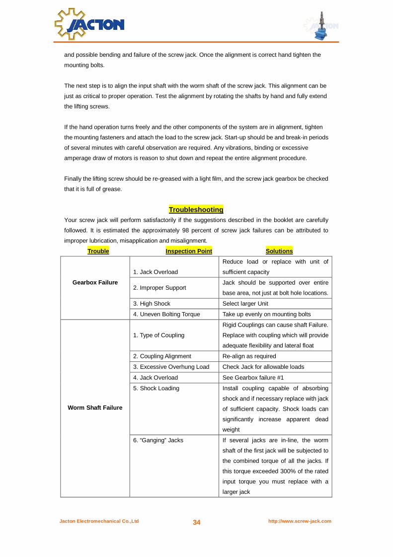
Troubleshooting Your screw jack will perform satisfactorily if the suggestions described in the booklet are carefully
followed. It is estimated the approximately 98 percent of screw jack failures can be attributed to
improper lubrication, misapplication and misalignment.
Trouble Inspection Point Solutions
1. Jack Overload
Reduce load or replace with unit of
sufficient capacity
2. Improper Support Jack should be supported over entire
base area, not just at bolt hole locations.
3. High Shock Select larger Unit
Gearbox Failure
4. Uneven Bolting Torque Take up evenly on mounting bolts
1. Type of Coupling
Rigid Couplings can cause shaft Failure.
Replace with coupling which will provide
adequate flexibility and lateral float
2. Coupling Alignment Re-align as required
3. Excessive Overhung Load Check Jack for allowable loads
4. Jack Overload See Gearbox failure #1
5. Shock Loading Install coupling capable of absorbing
shock and if necessary replace with jack
of sufficient capacity. Shock loads can
significantly increase apparent dead
weight
Worm Shaft Failure
6. “Ganging” Jacks If several jacks are in-line, the worm
shaft of the first jack will be subjected to
the combined torque of all the jacks. If
this torque exceeded 300% of the rated
input torque you must replace with a
larger jack
Jacton Electromechanical Co.,Ltd http://www.screw-jack.com 35
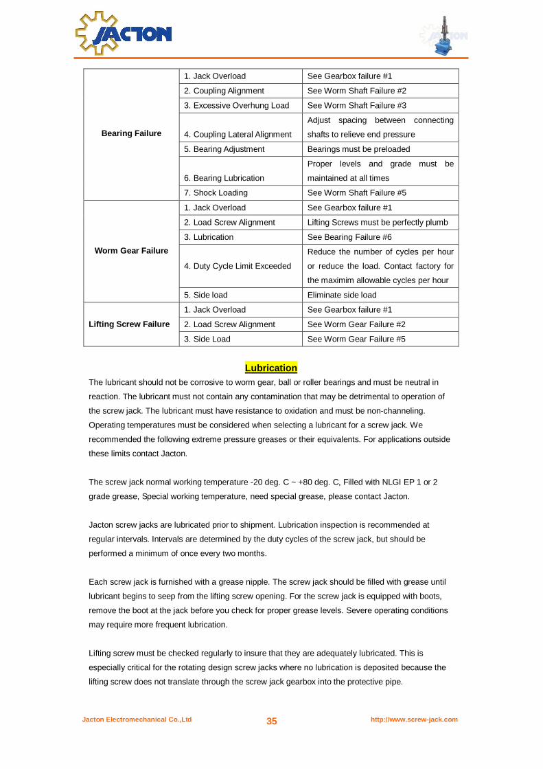
1. Jack Overload See Gearbox failure #1
2. Coupling Alignment See Worm Shaft Failure #2
3. Excessive Overhung Load See Worm Shaft Failure #3
4. Coupling Lateral Alignment
Adjust spacing between connecting
shafts to relieve end pressure
5. Bearing Adjustment Bearings must be preloaded
6. Bearing Lubrication
Proper levels and grade must be
maintained at all times
Bearing Failure
7. Shock Loading See Worm Shaft Failure #5
1. Jack Overload See Gearbox failure #1
2. Load Screw Alignment Lifting Screws must be perfectly plumb
3. Lubrication See Bearing Failure #6
4. Duty Cycle Limit Exceeded
Reduce the number of cycles per hour
or reduce the load. Contact factory for
the maximim allowable cycles per hour
Worm Gear Failure
5. Side load Eliminate side load
1. Jack Overload See Gearbox failure #1
2. Load Screw Alignment See Worm Gear Failure #2
Lifting Screw Failure
3. Side Load See Worm Gear Failure #5
Lubrication The lubricant should not be corrosive to worm gear, ball or roller bearings and must be neutral in
reaction. The lubricant must not contain any contamination that may be detrimental to operation of
the screw jack. The lubricant must have resistance to oxidation and must be non-channeling.
Operating temperatures must be considered when selecting a lubricant for a screw jack. We
recommended the following extreme pressure greases or their equivalents. For applications outside
these limits contact Jacton.
The screw jack normal working temperature -20 deg. C ~ +80 deg. C, Filled with NLGI EP 1 or 2
grade grease, Special working temperature, need special grease, please contact Jacton.
Jacton screw jacks are lubricated prior to shipment. Lubrication inspection is recommended at
regular intervals. Intervals are determined by the duty cycles of the screw jack, but should be
performed a minimum of once every two months.
Each screw jack is furnished with a grease nipple. The screw jack should be filled with grease until
lubricant begins to seep from the lifting screw opening. For the screw jack is equipped with boots,
remove the boot at the jack before you check for proper grease levels. Severe operating conditions
may require more frequent lubrication.
Lifting screw must be checked regularly to insure that they are adequately lubricated. This is
especially critical for the rotating design screw jacks where no lubrication is deposited because the
lifting screw does not translate through the screw jack gearbox into the protective pipe.
Jacton Electromechanical Co.,Ltd http://www.screw-jack.com 36
Maintenance Instructions All mounting bolts must be retightened after a short period of operation. Under extreme operating
conditions, the wear on the worm gear must be checked at shorter intervals, depending on the
power-on time, by inspecting the play in the thread. The worm gear must be replaced if the axial
backlash with a single-start thread is more than one-quarter of the thread pitch. After checking the
wear, screw jack should be re-assembled by a fitter. Check carefully that rotation is smooth and light
and free from axial play.
The Lifting screw must be kept free of contaminants and should be lubricated. If possible, lifting
screw should be booted or returned to retracted position when it's not in use.
Along with periodic inspection, check the alignment of the lifting screw to the load. Misalignment will
cause premature wear and possible failure. The load should be centered on the axis of the lifting
screw and motion should be parallel to the axis of the lifting screw. The power output shafting must
be aligned with respect to the screw jack input shaft. Binding during rotation will cause premature
wear. After the screw jacks, connecting shafts, couplings, bevel gearboxes and gear reducers are
coupled together in a system, it should be possible to rotate the shafts to fully extend the unloaded
screw jacks by hand.
The screw jacks are lubricated by the Jacton and are ready for operation on delivery. The translating
screw configurations must be lubricated via their grease nipples with one of the greases specified
below at intervals of 30 – 50 operating hours. The lifting screw should be cleaned and greased at the
same time. We recommend that the screw jack gearbox be cleaned to remove old grease and refilled
with fresh grease after every 600 operating hours or every 18 months. The screw jacks can
disassembly and assembly easily:
1. dismount the screw jack and clean.
2. disassemble the lifting screw and lifting screw protective pipe (only for translating screw).
3. Remove locking screws for screw jack gearbox cover.
4. Wash out the screw jack gearbox and components with a suitable wash medium.
5. Refill with grease
Jacton Electromechanical Co.,Ltd http://www.screw-jack.com 37
What is the difference between an acme screw jack and a ball screw jack?
The acme screw jack uses an acme threaded screw that is completely self-locking, meaning it will
hold its position without a brake mechanism or locking systems. Ball screw jack use ball screws to
convert rotary motion to linear movement, and require approx. 1/3 the horsepower compared to a
acme screw jack. Due to the efficiency of the ball screw, brake mechanism must be used to stop and
hold the load screw in position. Brake mechanism is also recommended for use on any screw jack if
vibration is present.
Why use an acme screw jack and a ball screw jack?
One type of screw jack is usually better suited to the operating conditions. Typically, fast travel speed
and frequent cycle times may be more suited to a ball screw jack, particularly as the load approaches
the rated capacity of the screw jack. High load at slow travel speed, less frequent cycles and the
ability to hold the load in position when the system is at rest may be better suited for an acme screw
jack.
How do I operate the screw jack?
Most screw jacks are operated by electric motor, but air motors and hydraulic motors can also be
used. Hand wheel or crank handle can be used for manual operation.
Can I use a larger motor than required in specifications?
Yes, but it is not recommended. The screw jack or jack system components could be
damaged if an oversize motor is used. Travel limit switches control must be used for each end of
travel to stop the motor. If using solid mechanical stops, screw jack components can be subject to
shock load conditions and oversize motors can cause catastrophic failure of stops and other
components.
How do I stop the screw jack at the travel limits?
Limit switches or other controls must be used to shut off the motor when the screw jack has reached
its full extended or retracted position. Solid mechanical stops are not recommended. Their continued
use can cause severe damage to the screw jack.
Can different size screw jacks be used in the same system?
Yes, as long as the equal travel length per full turn of worm shaft input. This is sometimes done to
accommodate varying load conditions.
What is the screw jack system efficiency?
2 screw jack system efficiency is 95%, 3 screw jack system efficiency is 90%, 4 screw jack system
efficiency is 85%, 6 screw jack system efficiency is 80%. Bevel gearbox efficiency is 98%. Single
reduction helical gear reducer efficiency is 98%, Double reduction helical gear reducer efficiency is
97%. Worm gear reducer efficiency is horsepower out x 100 / horsepower in
Frequently Asked Questions

Jacton Electromechanical Co.,Ltd http://www.screw-jack.com 38
What is the maximum input speed?
Jacton screw jack can be run at 1500Rpm. A gear motor, helical gear reducer, or a worm gear
reducer is used to reduce the input Rpm to the screw jack to provide the required travel speed of the
lifting screw. Many Jacton screw jacks can be driven directly by 1500Rpm and 900Rpm electric
motors. Electric motors and reducers are available mounted directly to many Jacton screw jacks
models.
What causes heat build up in the screw jack?
The screw jack is a mechanical gearbox assembly. The friction of the worm and worm gear, lifting
screw and worm gear, bearings and seals generate heat while the screw jack is operating. The
combination of travel, loading, and input speed all affect the temperature rise of the screw jack.
Jacton screw jack sizing calculations take these variables into account to insure that you select the
right screw jack model for your application.
What is the screw jack load capacity and travel?
This is based on the relationship of the lifting screw diameter and the length. Lifting screws in tension
are rated for the full capacity of the screw jack, regardless of length, providing they do not rotate
faster than the critical speed. For the lifting screw in compression, capacity is limited by the screw
jack’s permissible buckling load. The permissible buckling load of a lifting screw is reduced as the
lifting screw gets longer. Use the maximum extended lifting screw length when using the permissible
buckling load charts to determine screw jack load capacity.
How do I determine the full-extended lifting screw length?
The extended lifting screw length is normally equal to the travel stroke. If screw jack is equipped with
bellows boot and stop nut, must be added the bellows boot full retract length and the addition stop
nut or special closed height. These must be increased the extended lifting screw length. For inverted
screw jack, the thickness of the mounting structure must be included. This total extended lifting screw
length should be used when determining the permissible buckling load of the screw jack.
Should the load being positioned be guided?
It is highly recommended that the load be guided, however, it is not necessary. A guided system will
provide more column stability and allow longer screw jack travel. Column length is greatly reduced on
unguided systems. External load forces common with unguided systems are detrimental to the life
and operation of the screw jack.
Can the screw jack withstand side loading or a bending moment?
Yes, but this is not recommended. Consult Jacton if this condition will be present. These types of
loads apply greater forces on the screw jack and housing assembly causing premature wear. Guides
are highly recommended and should be used to eliminate side and bending loads.
Can the screw jack withstand shock loading?
This is not recommended. Oversized screw jacks are required to handle shock loads. Solid thrust
bearings are also available in many screw jack models when constant vibration and shock are
present in an application.
Jacton Electromechanical Co.,Ltd http://www.screw-jack.com 39
What is the difference between upright and inverted screw jack configurations?
The difference between an upright and an inverted screw jack is the location at which the lifting screw
exits the jack relative to the jack gearbox. For example, an upright screw jack’s lifting screw exits the
jack opposite the gearbox. An inverted screw jack’s lifting screw exits the jack on the same side as
the gearbox. The choice between inverted and upright screw jack is dependent upon the application.
Note: An upright screw jack mounted upside down is still referred to as an upright screw jack.
How is the linear travel speed calculated?
Each screw jack has an inherent number show lifting screw travel per full turn of worm shaft input.
The result of the screw jack is equal to the lifting screw pitch divided by worm gear ratio. For
example, JT-10T model screw jack, screw pitch 8mm, high worm gear ratio 1/8, the lifting screw
travel is 1mm per full turn of worm shaft input. If 900Rpm is applied to the worm shaft, the linear
travel speed is 900Rpm multiplied by 1mm/r, equal to 900 millimeter per minute.
Are screw jacks lubricated prior to shipment?
All Jacton worm gear screw jacks and ball screw jacks are lubricated with an extreme pressure NLGI
grade #1 or 2grease before leaving the factory. Bevel gear screw jacks are lubricated with NLGI
grade #1 grease or VG220 gear oil. The upper bearing and jack screw are grease lubricated while
the remaining internal components are oil lubricated. They are grease lubricated prior to shipment.
What electric motors options are available?
Electric motor options vary among product lines. Customers can use AC 3-phase motor, AC
single-phase motor, DC motor. Standard voltage of China is 380V/220V, 3-phase, 50Hz, or 220V,
single-phase, 50Hz. Customized international voltage motors like America 110V-single phase-60hz,
240V/480V-three phase-60Hz, other voltages 230V/240V-single phase-50hz, 400V/415V/440V-three
phase-50hz etc.
Are screw jacks corrosion resistant?
Stainless steel screw jacks are inherently corrosion resistant. All exposed surfaces are stainless steel
and aluminum bronze. Most other screw jacks can be modified with special finishes, coatings, and
seals.
Can bellows boots be supplied for an screw jack model with inverted screw?
Yes, but allowance must be made in the length of the lifting screw for both the closed height of the
boot and structure thickness. Since we can make no provision for attaching a boot on the underside
of your structure, we suggest that a circular plate similar to the lifting screw top plate be welded or
bolted to the bottom of your structure supporting the screw jack, thereby making it possible to use a
standard bellows boot.
Is there backlash between the lifting screw and worm gear?
Yes. This is necessary to allow for sliding or rolling action of the lifting screw through the worm gear.
Anti-backlash nut screw jack is available when the backlash needs to be minimized. Input torque
requirements are greater for anti-backlash nut screw jack.

Jacton Electromechanical Co.,Ltd http://www.screw-jack.com 40
How is the lifting screw protected?
Standard translating screw jack is fitted with a lifting screw protective pipe that stores the lifting screw
when the screw jack is in the closed position. Bellows boot is available and recommended to protect
the lifting screw in the extended position. Double bellows boots are required for rotating screw jack
with traveling nut.
How do I attach the load to be positioned to the lifting screw?
For translating screw jack, the lifting screw has a standard threaded end that can be used to attach
the load, top plate, clevis end, plain end and forked head are also available. For traveling nut design,
the traveling nut has a flange with mounting holes. The screw jack gearbox has a mounting base and
is also available with a clevis mount for double clevis requirements.
Will the lifting screw rotate?
Yes. You need to prevent the lifting screw from rotating to produce linear motion. The lifting screw will
not rotate in a multiple screw jack system with all the lifting screws attached to the same structure. If
rotation of the screw cannot be prevented in the application design, a keyed screw configuration is
available for either the acme screw jack and ball screw jack. Input torque will increase for keyed
screw jack and the capacity may be reduced to 25% of rating.
What is the maximum and minimum operating temperature?
Standard Jacton screw jacks are designed to operate at maximum 80 deg.C (185 deg.F) ambient
temperature. For higher temperatures, special grease and seals are required, contact Jacton of these
special requirements. Minimum minus 20 deg.C (minus 4 deg.F) ambient temperature. For lower
temperatures, special grease and seals are required, contact Jacton of these special requirements.
How do I lubricate a screw screw jack?
Use the proper grease. Fill the gearbox by pumping grease into the grease fittings supplied in the
screw jack housing. The lifting screws should have grease applied directly to them with a rag or
paintbrush. This must be done as part of a regularly scheduled maintenance program.
Jacton Electromechanical Co.,Ltd http://www.screw-jack.com 41
Company History
In 1997, Established Jacton Hardware Fabrication Plant, mainly processing kinds of hardware
following customers requirements. Occupied 500 square meters.
In 2000, Established domestic sales department, started to develop local market, mainly processing
gear transmission parts such as worm and worm gear, acme threads screw, square threads screw
and acme lead screw nut. Meanwhile, sales also sell straight bevel gear and spiral bevel gears for
customers.
In 2002, According to some regular customers of steel plants and machines manufacturers, which
used Taiwan screw jacks and bevel gearboxes, due to long delivery and high price, would affect the
normal operations. Jacton Hardware Fabrication Plant started to processing JT series trapezoidal
screw jack and JT series T type bevel gearbox following above customers samples.
In 2003, Established engineering department, research and development others models of JT series
trapezoidal screw jack and JT series T type bevel gearbox, and draw some factory production
drawings and local sales' customers drawing with 2d cad software.
In 2005, According to local market demands, Jacton Hardware Fabrication Plant is committed to
research and development JB/T8809-1998 standard JTB series ball screw jack and JTP series cubic
bevel gearbox.
In 2006, Because of local markets fiercely competitive. Established Hong Kong office - Jacton
International Limited with own US dollars and EURO account. Established international sales
department, focused on overseas markets. Meanwhile, "JACTON" as company only brand.
In 2008, According to int'l sales market report, cubic screw jacks are very popular in Europe and
America markets. After managements meetings, we started to develop JTC series cubic screw jacks.
In 2009, Jacton Hardware Fabrication Plant extension, occupied 5000 square meters. Company
improves the processes and products through technology investment, brings in advanced
technology, production and testing equipment.
In 2010, Jacton Hardware Fabrication Plant Passed ISO9001:2008 quality management system, we
are strictly implement the work flow of ISO9001:2008 certifications, which ensures oversea and local
customers are satisfaction with our screw jacks and bevel gearboxes and fast delivery time.
In 2012, In order to facilitating management, according to management decisions, sales department
and design department moved to Taibao business building. Meanwhile, Jacton Hardware Fabrication
Plant changed to be Dongguan Jacton Electromechanical Co.,Ltd.

Jacton Electromechanical Co.,Ltd http://www.screw-jack.com 42
Contact Us
Jacton Electromechanical Co.,Ltd
(Head Quarters)
1&2 Floors, Building F, Baisheng Industrial
Areas, No.34, Yongjun Road, Datang,
Dalingshan, Dongguan, Guangdong, China
Phone: 86 769 81585810
Mobile: 86 189 25569548
Jacton Electromechanical Co.,Ltd
(Sales Dept. & Design Dept.)
1118, Taibao Business Building, No.1
Langwei Rd, Xinan, Changan, Dongguan,
Guangdong, China
Phone: 86 769 81585852
Fax: 86 769 81620195
Jacton International Limited
(Hong Kong Branch)
Office 17,9/F.,Tower A,New Mandarin
Plaza,No.14,Science Museum Road,
Tsimshatsui,Kowloon,Hongkong
Tel: 852-2793-5511
Fax:852-3590-2333
Contact Us
General Enquiries: [email protected]
Online Skype: jactonjack (Warren)
Online Skype: jactongearbox (Abby)
Website: http://www.screw-jack.com
Urgently required, please directly make a call
to Warren +86 13532830851