Embed Size (px)
Citation preview

Brussels, 22 February 2017
Clean Sky 2 Information Day dedicated to the
6th Call for Proposal (CfP06)
Innovative Low Power De-Icing System
JTI-CS2-2017-CFP06-REG-01-09
2
• Estimated Funding Topic Value: 1200k€
• Duration: 36 months
• Start date: Q1 2018 (indicative)
• CfP short description:
To design, develop and manufacture a demonstrator of Low Power De-Icing System, including the leading edge wing section.
The demonstrator will be tested up to TRL 5 in an Ice Wind Tunnel (not part of this Topic); the Applicant shall also assure the support to testing activity for system performance validation.
REG-01-09 Topic Intro
3
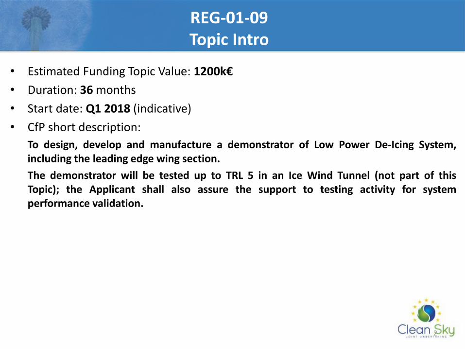
REG-01-09 REG IADP WBS Overview
WP 1
High Efficiency Regional A/C
Regional IADP
WP 2
Technologies Development
WP 2.1
Adaptive Electrical Wing
WP 2.2
Regional Avionics
WP 2.3
Energy Optimized Regional A/C
WP 2.4
Innovative FCS
WP 0
Management
WP 3
Demonstrations
WP 4
Demonstrations Analysis
WP 3.1
Airvehicle Flight Test Bed (FTB#1)
WP 3.2
Fuselage/Cabin Ground Demonstrator
WP 3.3
Flight Simulator
WP 3.4
Iron Bird
WP 3.5
High Lift Advanced Turboprop (FTB#2)
WP 2.3.1 Low Power
WIPS
WP 2.3.4
Advanced EPGDS
WP 2.3.2 Electrical LGS
WP 2.3.5 Electrical ECS
WP 2.3.6 Innovative Propeller
WP 2.3.3 Thermal
Management
R-IADP Related WPs
REG-01-09 Scope of the work
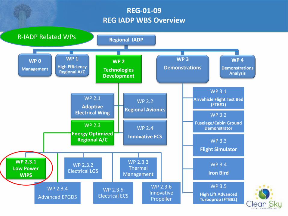
WP 2.3.1 Key Objectives & Technologies
• Study of Low Power Wing Ice Protection System technologies including mechanical/electrical integration requirements & constraints
• Modeling activities (thermal model not part of this topic) for system optimal sizing and performance validation
• Certification approach for Regional A/C WIPS at early stage (new Appendix O condition) to be compliant with CS 25.1420
• Increasing TRL targets to 5 (in CS GRA hybrid technology only at TRL 2/3)
FULL THERMAL ICE PROTECTION SYSTEM
IWT ACTIVITY
REG-01-09 Scope of the work
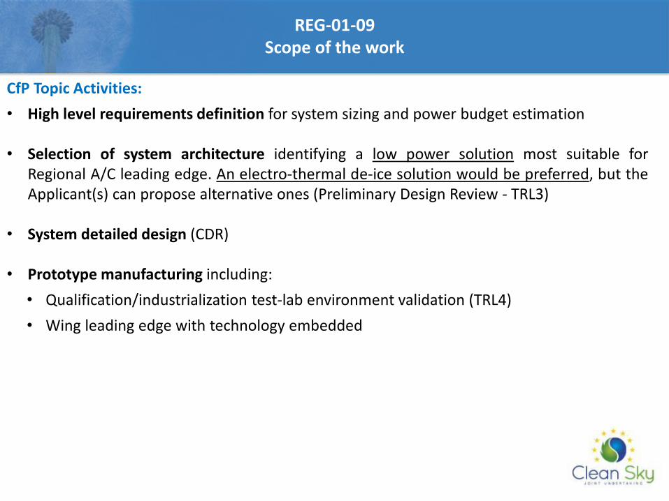
CfP Topic Activities:
• High level requirements definition for system sizing and power budget estimation
• Selection of system architecture identifying a low power solution most suitable for Regional A/C leading edge. An electro-thermal de-ice solution would be preferred, but the Applicant(s) can propose alternative ones (Preliminary Design Review - TRL3)
• System detailed design (CDR)
• Prototype manufacturing including:
• Qualification/industrialization test-lab environment validation (TRL4)
• Wing leading edge with technology embedded
6
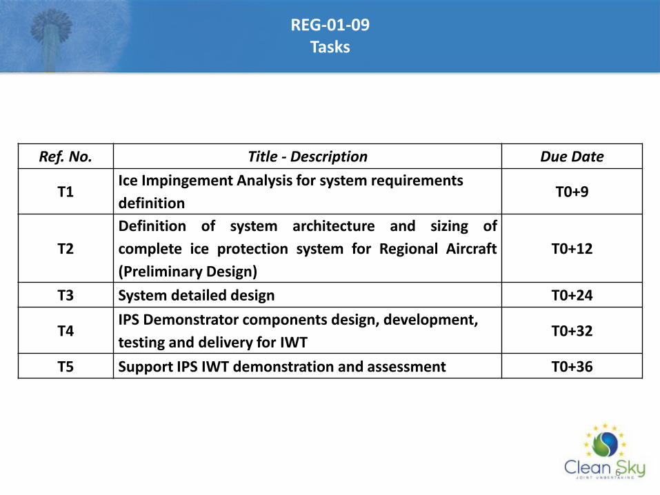
REG-01-09 Tasks
Ref. No. Title - Description Due Date
T1 Ice Impingement Analysis for system requirements
definition T0+9
T2
Definition of system architecture and sizing of
complete ice protection system for Regional Aircraft
(Preliminary Design)
T0+12
T3 System detailed design T0+24
T4 IPS Demonstrator components design, development,
testing and delivery for IWT T0+32
T5 Support IPS IWT demonstration and assessment T0+36
7
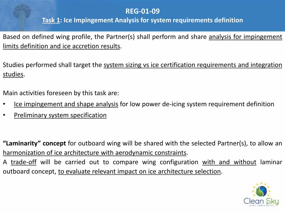
REG-01-09 Task 1: Ice Impingement Analysis for system requirements definition
Based on defined wing profile, the Partner(s) shall perform and share analysis for impingement
limits definition and ice accretion results.
Studies performed shall target the system sizing vs ice certification requirements and integration
studies.
Main activities foreseen by this task are:
• Ice impingement and shape analysis for low power de-icing system requirement definition
• Preliminary system specification
“Laminarity” concept for outboard wing will be shared with the selected Partner(s), to allow an
harmonization of ice architecture with aerodynamic constraints.
A trade-off will be carried out to compare wing configuration with and without laminar
outboard concept, to evaluate relevant impact on ice architecture selection.
8
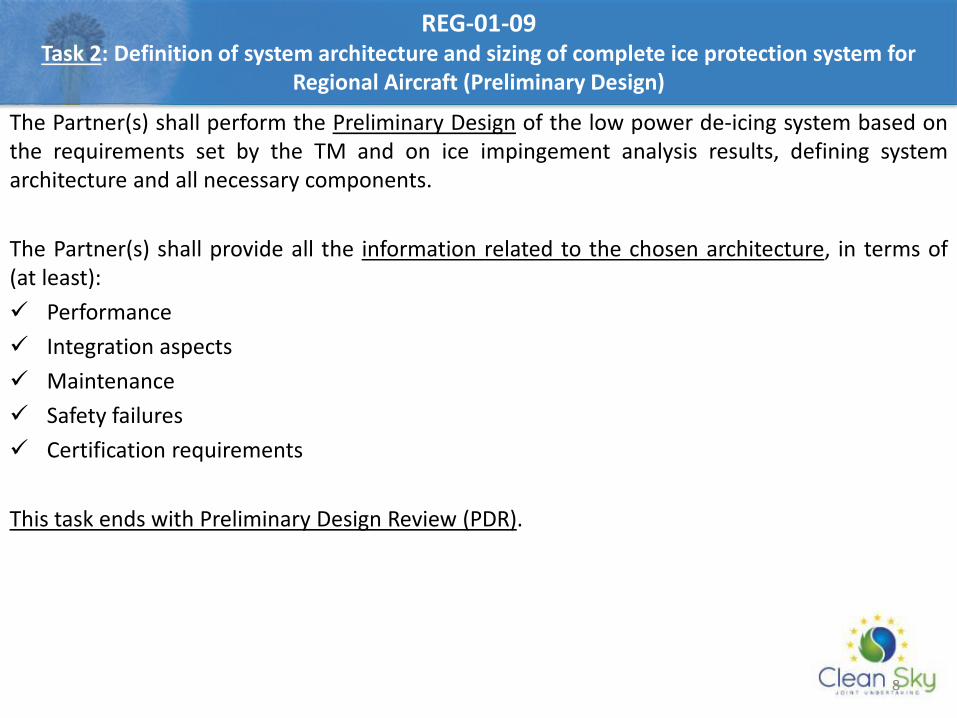
REG-01-09 Task 2: Definition of system architecture and sizing of complete ice protection system for
Regional Aircraft (Preliminary Design)
The Partner(s) shall perform the Preliminary Design of the low power de-icing system based on the requirements set by the TM and on ice impingement analysis results, defining system architecture and all necessary components.
The Partner(s) shall provide all the information related to the chosen architecture, in terms of (at least):
Performance
Integration aspects
Maintenance
Safety failures
Certification requirements
This task ends with Preliminary Design Review (PDR).
9
The Partner(s) shall perform the Detailed Design of the Low Power System:
• Perform the detailed design of all the system components/equipment
• Provide 2D drawings of all the components/equipment
• Update weight report
• Finalize the power & electrical load analysis
• Provide a preliminary IWT plan & procedure
• Test Article mechanical design
All the technical information provided during the preliminary design phase shall be updated.
This task ends with Critical Design Review (CDR).
REG-01-09 Task 3: System Detailed Design
10
The Partner(s) shall be responsible for the Test Article manufacturing and for the definition of the IWT test planning and procedure to demonstrate the effectiveness of the Low Power De-Icing System. The Partner(s) shall provide Test Article made of composite material including Low Power WIPS component (indicatively the wing section to be tested shall be the outboard with a chord-wise size of 1500 mm and span-wise size function of IWT test chamber size).
Selected Candidate(s) shall define:
• IPS configuration for test
• Lab test instrumentation and IWT instrumentation specification
• Control logic for test (e.g. D/I cycle activation, power regulation as function of ice accretion)
• Detailed planning and procedure for the IWT
• Test Article qualification to cover functional performance and environmental requirements With activities included inside this task, TRL 4 shall be reached.
REG-01-09 Task 4: IPS Demonstrator components design, development, testing and delivery for IWT
11
The IWT test campaign will be finalized to testing the system integrated into the wing section sample in a range of operating points covering the critical conditions for the Regional A/C. The selected Partner(s), in concurrence with TM, shall prepare an IWT Test Program oriented to tests execution. The IWT tests will be performed in the context of a separate complementary activity (not part of this call).
In this task the Partner(s) shall be responsible for:
• Installing the demonstrator and instrumentation in the IWT
• Record all the data after running in IWT
• Write the IWT test plan and IWT test report
• Update performance document for the complete system based on test results
With activities included inside this task , TRL 5 shall be reached.
REG-01-09 Task 5: Support IPS IWT demonstration and assessment
12
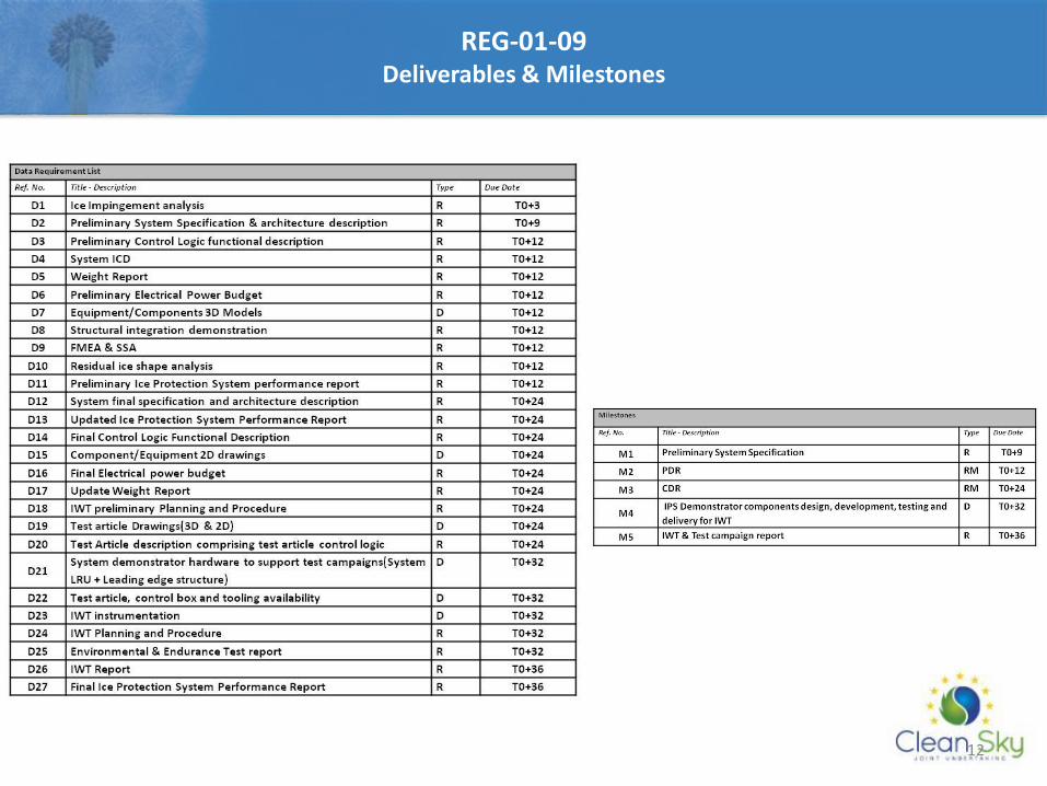
REG-01-09 Deliverables & Milestones
13
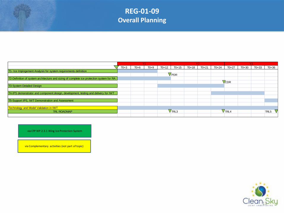
REG-01-09 Overall Planning
T0+3 T0+6 T0+9 T0+12 T0+15 T0+18 T0+21 T0+24 T0+27 T0+30 T0+33 T0+36
T1- Ice Impingement Analysis for system requirements definition
PDR
T2-Definition of system architecture and sizing of complete ice protection system for RA
CDR
T3-System Detailed Design
T4-IPS demonstrator and component design, development, testing and delivery for IWT
T5-Support IPS, IWT Demonstration and Assessment
Technology and Model Validation in IWT
TRL ROADMAP TRL3 TRL4 TRL5
Y2Y1 Y3
via CfP WP 2.3.1 Wing Ice Protection System
via Complementary activities (not part of topic)
14
REG-01-09 Special skills, Capabilities, Certification expected from the Applicant(s)
• Proven experience in the design and development of advanced technologies in the field of Anti-icing and De-icing Systems
• Numerical tools availability to assess thermal performance in Appendix C and O conditions
• Numerical tools availability to assess structure resistance under different kinds of steady and transient loads (thermal, mechanical, impact)
• Validation of numerical tools against previously performed test campaigns (icing wind tunnel, structural testing, impacts)
• Good experience and knowledge of aircraft icing issues
• Proven experience in the use of design, analysis and configuration management tools of the aeronautical industry
• IWT test rig experience
• Proven IWT test running experience
Applicant(s) should demonstrate experience in preparation and conduction of icing wind tunnel tests.

Innovation Takes Off
Q&A Any questions?

Brussels, 22 February 2017
Clean Sky 2 Information Day dedicated to the
6th Call for Proposal (CfP06)
E2-EM Supervisor and Control Algorithms
JTI-CS2-2017-CFP06-REG-01-10
17
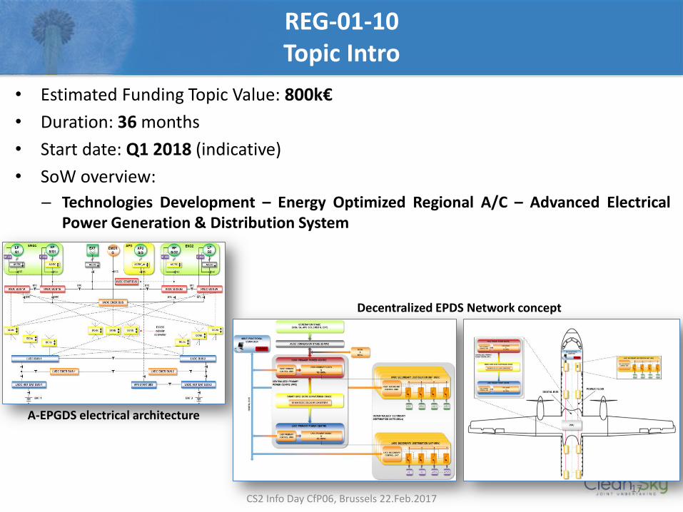
• Estimated Funding Topic Value: 800k€
• Duration: 36 months
• Start date: Q1 2018 (indicative)
• SoW overview:
– Technologies Development – Energy Optimized Regional A/C – Advanced Electrical Power Generation & Distribution System
Decentralized EPDS Network concept
A-EPGDS electrical architecture
CS2 Info Day CfP06, Brussels 22.Feb.2017
REG-01-10 Topic Intro
18
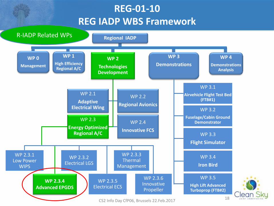
WP 1
High Efficiency Regional A/C
Regional IADP
WP 2
Technologies Development
WP 2.1
Adaptive Electrical Wing
WP 2.2
Regional Avionics
WP 2.3
Energy Optimized Regional A/C
WP 2.4
Innovative FCS
WP 0
Management
WP 3
Demonstrations
WP 4
Demonstrations Analysis
WP 3.1
Airvehicle Flight Test Bed (FTB#1)
WP 3.2
Fuselage/Cabin Ground Demonstrator
WP 3.3
Flight Simulator
WP 3.4
Iron Bird
WP 3.5
High Lift Advanced Turboprop (FTB#2)
WP 2.3.1 Low Power
WIPS
WP 2.3.4 Advanced EPGDS
WP 2.3.2 Electrical LGS
WP 2.3.5 Electrical ECS
WP 2.3.6 Innovative Propeller
WP 2.3.3 Thermal
Management
R-IADP Related WPs
CS2 Info Day CfP06, Brussels 22.Feb.2017
REG-01-10 REG IADP WBS Framework
19
REG-01-10 Objectives
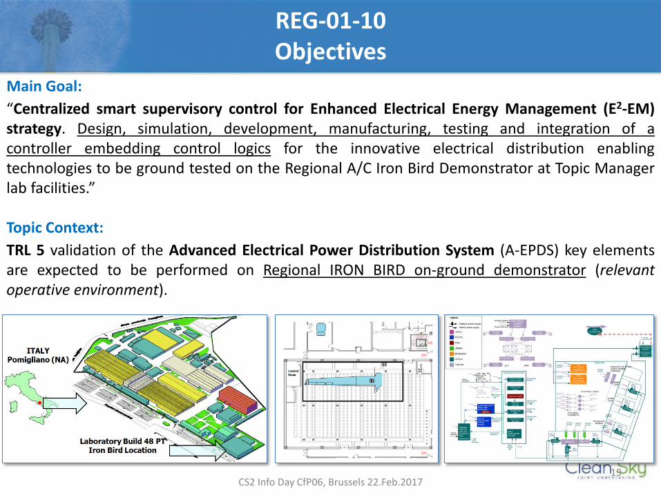
Main Goal:
“Centralized smart supervisory control for Enhanced Electrical Energy Management (E2-EM) strategy. Design, simulation, development, manufacturing, testing and integration of a controller embedding control logics for the innovative electrical distribution enabling technologies to be ground tested on the Regional A/C Iron Bird Demonstrator at Topic Manager lab facilities.” Topic Context:
TRL 5 validation of the Advanced Electrical Power Distribution System (A-EPDS) key elements are expected to be performed on Regional IRON BIRD on-ground demonstrator (relevant operative environment).
CS2 Info Day CfP06, Brussels 22.Feb.2017
20
REG-01-10 Background
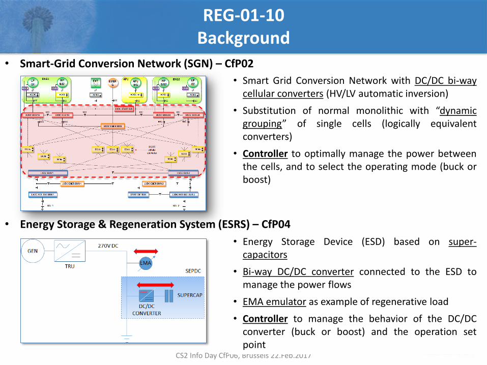
• Smart-Grid Conversion Network (SGN) – CfP02
• Energy Storage & Regeneration System (ESRS) – CfP04
CS2 Info Day CfP06, Brussels 22.Feb.2017
• Smart Grid Conversion Network with DC/DC bi-way cellular converters (HV/LV automatic inversion)
• Substitution of normal monolithic with “dynamic grouping” of single cells (logically equivalent converters)
• Controller to optimally manage the power between the cells, and to select the operating mode (buck or boost)
• Energy Storage Device (ESD) based on super-capacitors
• Bi-way DC/DC converter connected to the ESD to manage the power flows
• EMA emulator as example of regenerative load
• Controller to manage the behavior of the DC/DC converter (buck or boost) and the operation set point
21
REG-01-10 Key Points (1/2)
• Enhanced Electrical Energy Management (E2-EM)
DESIGN & MODELLING
Higher level “Centralized Smart Supervisory” (CSS) hardware controller able to manage the SGN and ESRS lower level controllers to implement an optimal sharing of the available electrical power on-board during failures and/or overload conditions, thus not relying on main generators overload capabilities CSS control system to be fully interfaced with SGN and ESRS subsystems, as well as with the IRON BIRD, by appropriate communication protocols (equipment and test rig ICD’s to be provided by TM at early stage of the Project) Formal mathematical approach is required for the CSS control logics design (for proof of correctness) Global E2-EM control and monitoring strategy to be modeled (at functional level) and tested in a simulation environment (architecture provided by TM)
CS2 Info Day CfP06, Brussels 22.Feb.2017
22
REG-01-10 Key Points (2/2)
• Enhanced Electrical Energy Management (E2-EM)
MANUFACTURING & TESTING CSS controller with embedded supervision logics shall be part of an hardware equipment, to be integrated onto Iron Bird and interfaced with SGN and ESRS via CAN network (preferred) Automatic or semi-automatic firmware translation is an asset, in order to minimize the chance of programming errors Hardware In the Loop techniques are required to provide evidence of CSS controller correct operations before integration on the Iron Bird Documentation (ICDs) required for correct electrical, mechanical and control interfaces with the electrical test rig, SGN and ESRS subsystems will be provided by TM at the early stage of the Project Qualification activities facilitating the preparation of the equipment for higher level TRL step will be an asset
CS2 Info Day CfP06, Brussels 22.Feb.2017
23
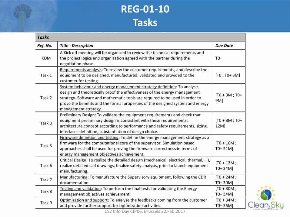
REG-01-10 Tasks
CS2 Info Day CfP06, Brussels 22.Feb.2017
Tasks
Ref. No. Title - Description Due Date
KOM A Kick off meeting will be organized to review the technical requirements and the project logics and organization agreed with the partner during the negotiation phase.
T0
Task 1 Requirements analysis: To review the customer requirements, and describe the equipment to be designed, manufactured, validated and provided to the customer for testing.
[T0 ; T0+ 3M]
Task 2
System behaviour and energy management strategy definition: To analyse, design and theoretically proof the effectiveness of the energy management strategy. Software and mathematic tools are required to be used in order to prove the benefits and the formal properties of the designed system and energy management strategy.
[T0 + 3M ; T0+ 9M]
Task 3
Preliminary Design: To validate the equipment requirements and check that equipment preliminary design is consistent with these requirements: architecture concept according to performance and safety requirements, sizing, interfaces definition, substantiation of design choice.
[T0 + 3M ; T0+ 12M]
Task 5
Firmware definition and testing: To define the energy management strategy as a firmware for the computational core of the supervisor. Simulation based approaches shall be used for proving the firmware correctness in terms of energy management objectives achievement.
[T0 + 16M ; T0+ 21M]
Task 6 Critical Design: To realize the detailed design (mechanical, electrical, thermal, …), realize detailed cad drawings, finalize safety analysis, prior to launch equipment manufacturing.
[T0 + 12M ; T0+ 24M]
Task 7 Manufacturing: To manufacture the Supervisory equipment, following the CDR documentation.
[T0 + 24M ; T0+ 30M]
Task 8 Testing and validation: To perform the final tests for validating the Energy management objectives achievement.
[T0 + 30M ; T0+ 34M]
Task 9 Optimization and support: To analyse the feedbacks coming from the customer and provide further support for optimization activities.
[T0 + 34M ; T0+ 36M]
24
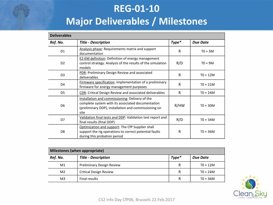
REG-01-10 Major Deliverables / Milestones
CS2 Info Day CfP06, Brussels 22.Feb.2017
Deliverables
Ref. No. Title - Description Type* Due Date
D1 Analysis phase: Requirements matrix and support documentation
R T0 + 3M
D2 E2-EM definition: Definition of energy management control strategy. Analysis of the results of the simulation models
R/D T0 + 9M
D3 PDR: Preliminary Design Review and associated deliverables
R T0 + 12M
D4 Firmware specification: Implementation of a preliminary firmware for energy management purposes
R T0 + 21M
D5 CDR: Critical Design Review and associated deliverables R T0 + 24M
D6
Installation and commissioning: Delivery of the complete system with its associated documentation (preliminary DDP), installation and commissioning on site
R/HW T0 + 30M
D7 Validation final tests and DDP: Validation test report and final results (final DDP)
R/D T0 + 34M
D8 Optimization and support: The CfP Supplier shall support the rig operations to correct potential faults during this probation period
R T0 + 36M
Milestones (when appropriate)
Ref. No. Title - Description Type* Due Date
M1 Preliminary Design Review R T0 + 12M
M2 Critical Design Review R T0 + 24M
M3 Final results R T0 + 36M