Embed Size (px)
Citation preview
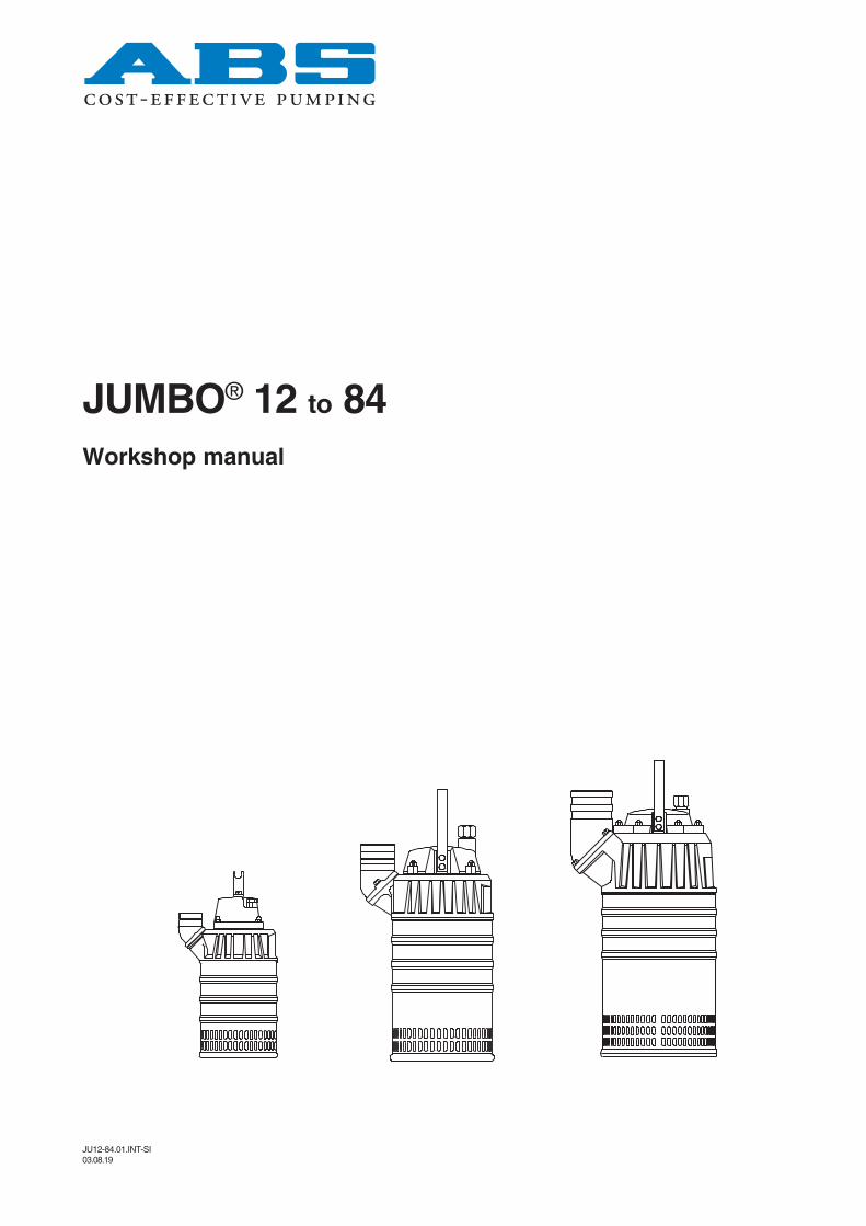
JU12-84.01.INT-SI03.08.19
Workshop manual
JUMBO® 12 to 84
JUMBO®
2
Index1.0 General Page 31.1 Scope of manual 31.2 Complete overhaul 3
2.0 Dismantling 32.1 Base plate 32.2 Diffusor, cooling jacket 32.3 Oil draining 32.4 Impeller 32.5 Shaft seal 32.6 Rotor unit 42.7 Ball bearing 42.8 Cover and cable gland 42.9 Stator with contactor 4
3.0 Insulation test 53.1 Thermal contacts 54.0 Exchange of stator 64.1 Removal of stator 64.2 Mounting of stator 64.3 Thermal contacts 6
5.0 Assembly 75.1 General 75.2 Stator unit, Contactor, Main cover 75.3 Cable and gland cover 75.4 Ball bearings and rotor unit 75.5 Secondary seal 85.6 Primary seal and wear plate 85.7 Impeller 85.8 Refilling of oil 95.9 Diffusor and outer casing 9
6.0 JUMBO 84 HD - 50Hz 10
7.0 Testing 10
8.0 Electrical connections 118.1 Single phase JUMBO 12W,
JUMBO 14W and JUMBO 24W 118.2 Three phase direct start 118.3 The coil of the contactor 118.4 Three phase star delta starting 118.5 Fuses 11
9.0 Sectional drawing 12
JUMBO®
3
JUMBO®
1.0 General
1.1 Scope of manualThis manual is to be used only by the authorisedABS service workshops. For the installation andthe operation of the pump please use appropriateinstructions.
1.2 Complete overhaulA complete overhaul of the pump should becarried out if there has been water or oil in themotor housing or if the pump has been in dailyoperation for more than a year. At low utilization ofthe pump the overhaul intervals can be extended.Dismantle the pump completely, replace damagedand worn parts. Clean all sealing surfaces andcheck that they are not damaged. If water or oilhas leaked into the motor housing, inspect andreplace ball bearings and shaft seals as required.
Use only ABS spare parts.
WarningAlways check that the pump is disconnected fromthe electric power supply, and connot beenergized, prior to any work being carried out.
2.0 Dismantling
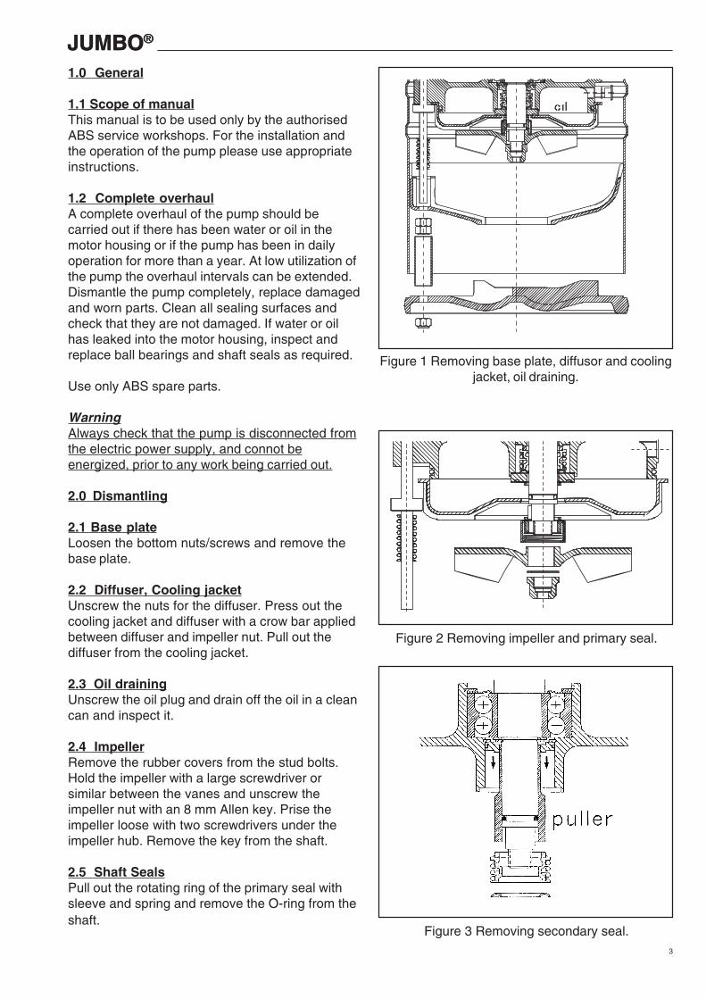
2.1 Base plateLoosen the bottom nuts/screws and remove thebase plate.
2.2 Diffuser, Cooling jacketUnscrew the nuts for the diffuser. Press out thecooling jacket and diffuser with a crow bar appliedbetween diffuser and impeller nut. Pull out thediffuser from the cooling jacket.
2.3 Oil drainingUnscrew the oil plug and drain off the oil in a cleancan and inspect it.
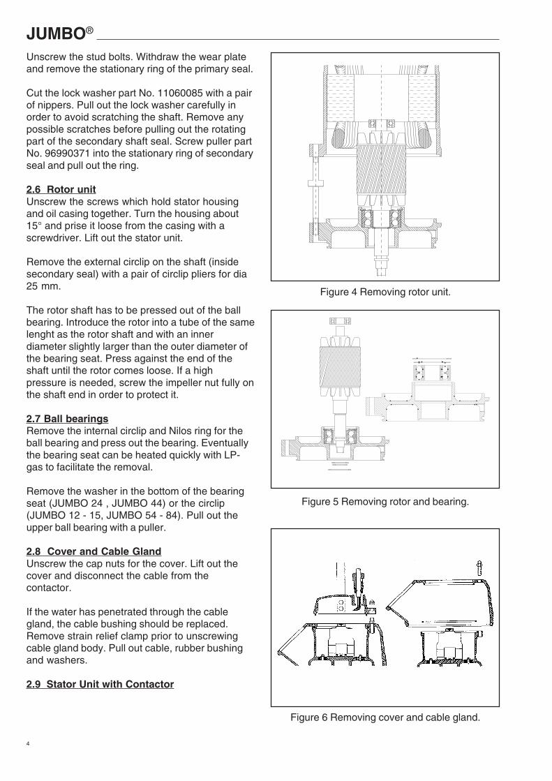
2.4 ImpellerRemove the rubber covers from the stud bolts.Hold the impeller with a large screwdriver orsimilar between the vanes and unscrew theimpeller nut with an 8 mm Allen key. Prise theimpeller loose with two screwdrivers under theimpeller hub. Remove the key from the shaft.
2.5 Shaft SealsPull out the rotating ring of the primary seal withsleeve and spring and remove the O-ring from theshaft.
Figure 1 Removing base plate, diffusor and coolingjacket, oil draining.
Figure 2 Removing impeller and primary seal.
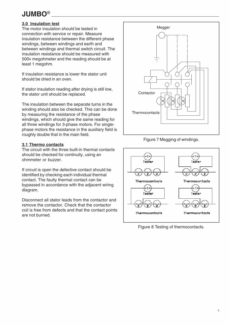
Figure 3 Removing secondary seal.
JUMBO®
4
Unscrew the stud bolts. Withdraw the wear plateand remove the stationary ring of the primary seal.
Cut the lock washer part No. 11060085 with a pairof nippers. Pull out the lock washer carefully inorder to avoid scratching the shaft. Remove anypossible scratches before pulling out the rotatingpart of the secondary shaft seal. Screw puller partNo. 96990371 into the stationary ring of secondaryseal and pull out the ring.
2.6 Rotor unitUnscrew the screws which hold stator housingand oil casing together. Turn the housing about15° and prise it loose from the casing with ascrewdriver. Lift out the stator unit.
Remove the external circlip on the shaft (insidesecondary seal) with a pair of circlip pliers for dia25 mm.
The rotor shaft has to be pressed out of the ballbearing. Introduce the rotor into a tube of the samelenght as the rotor shaft and with an innerdiameter slightly larger than the outer diameter ofthe bearing seat. Press against the end of theshaft until the rotor comes loose. If a highpressure is needed, screw the impeller nut fully onthe shaft end in order to protect it.
2.7 Ball bearingsRemove the internal circlip and Nilos ring for theball bearing and press out the bearing. Eventuallythe bearing seat can be heated quickly with LP-gas to facilitate the removal.
Remove the washer in the bottom of the bearingseat (JUMBO 24 , JUMBO 44) or the circlip(JUMBO 12 - 15, JUMBO 54 - 84). Pull out theupper ball bearing with a puller.
2.8 Cover and Cable GlandUnscrew the cap nuts for the cover. Lift out thecover and disconnect the cable from thecontactor.
If the water has penetrated through the cablegland, the cable bushing should be replaced.Remove strain relief clamp prior to unscrewingcable gland body. Pull out cable, rubber bushingand washers.
2.9 Stator Unit with Contactor
Figure 5 Removing rotor and bearing.
Figure 4 Removing rotor unit.
Figure 6 Removing cover and cable gland.
JUMBO®
5
Megger
Contactor
Thermocontacts
3.0 Insulation testThe motor insulation should be tested inconnection with service or repair. Measureinsulation resistance between the different phasewindings, between windings and earth andbetween windings and thermal switch circuit. Theinsulation resistance should be measured with500v megohmeter and the reading should be atleast 1 megohm.
If insulation resistance is lower the stator unitshould be dried in an oven.
If stator insulation reading after drying is still low,the stator unit should be replaced.
The insulation between the separate turns in thewinding should also be checked. This can be doneby measuring the resistance of the phasewindings, which should give the same reading forall three windings for 3-phase motors. For single-phase motors the resistance in the auxiliary field isroughly double that in the main field.
3.1 Thermo contactsThe circuit with the three built-in thermal contactsshould be checked for continuity, using anohmmeter or buzzer.
If circuit is open the defective contact should beidentified by checking each individual thermalcontact. The faulty thermal contact can bebypassed in accordance with the adjacent wiringdiagram.
Disconnect all stator leads from the contactor andremove the contactor. Check that the contactorcoil is free from defects and that the contact pointsare not burned.
Figure 7 Megging of windings.
Figure 8 Testing of thermocontacts.
JUMBO®
6
4.0 Exchange of Stator
4.1 Removal of statorLoosen nuts for the wire seal and pull out theseals. Pull out the cables and arrange them soas to avoid jamming when the stator is falling outof the housing.Remove the O-ring in the upper bearing seat.
Block up the housing so that the stator can dropfreely out of the housing. It is important that thesealing surfaces of the housing will not bedamaged.
Heat the housing quickly with two LP-gas flamesat the stator laminations and downwards until thestator drops out at a temperature of about 250°C.
Clean the housing and check it for damages,particularly on sealing surfaces and in ballbearing seat. If damages cannot be corrected,the housing must be rejected.
4.2 Mounting of statorBlock up the new stator and make sure that thehousing can be fully pushed down onto thestator. Protect the stator insulation for damagesand put down the terminal wires (free frominsulation resin and smooth) into the stator toavoid contact with the hot housing duringassembly.
Heat the housing with two LP-gas flames toabout 250<198>C. With two 25 mm nozzles thiswill take about one minute. Take the hot housingwith heat-resistant gloves and push it down to itsstop over the housing.
Note! Locate the holes for the terminal cables inthe housing about 10 mm from the exit of thecable groups on the winding head.
When the housing has been mounted it may becooled by compressed air.
When the housing has cooled down the terminalcables can be pulled up through the holes in thehousing with a hook made of steel wire. Mountthe cable bushings (6-hole seals) on the twogroups of cables.
4.3 Thermal contactsThe thermal switches are connected in seriesand the joints should be well insulated.
Figure 9 Removing wire seal.
Figure 10 Removing stator from housing.
JUMBO®
7
5.0 Assembly
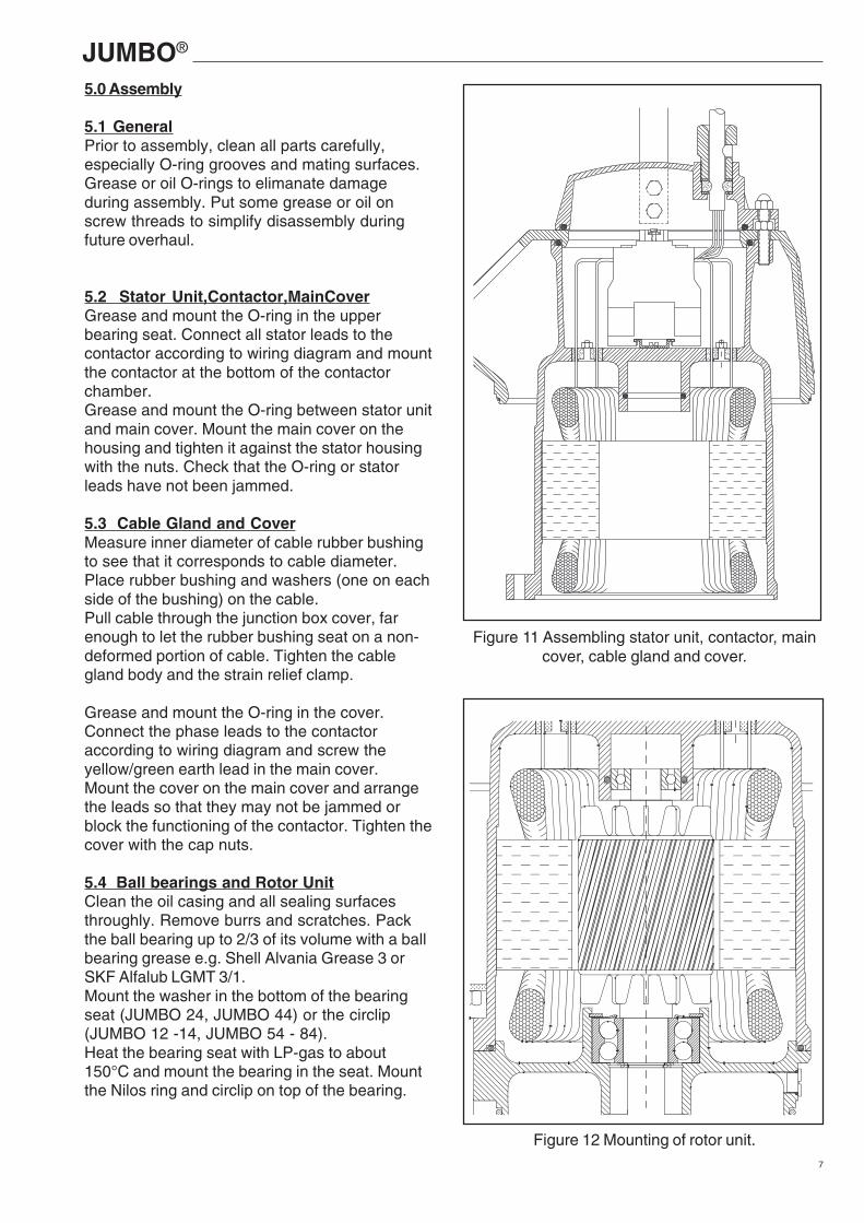
5.1 GeneralPrior to assembly, clean all parts carefully,especially O-ring grooves and mating surfaces.Grease or oil O-rings to elimanate damageduring assembly. Put some grease or oil onscrew threads to simplify disassembly duringfuture overhaul.
5.2 Stator Unit,Contactor,MainCoverGrease and mount the O-ring in the upperbearing seat. Connect all stator leads to thecontactor according to wiring diagram and mountthe contactor at the bottom of the contactorchamber.Grease and mount the O-ring between stator unitand main cover. Mount the main cover on thehousing and tighten it against the stator housingwith the nuts. Check that the O-ring or statorleads have not been jammed.
5.3 Cable Gland and CoverMeasure inner diameter of cable rubber bushingto see that it corresponds to cable diameter.Place rubber bushing and washers (one on eachside of the bushing) on the cable.Pull cable through the junction box cover, farenough to let the rubber bushing seat on a non-deformed portion of cable. Tighten the cablegland body and the strain relief clamp.
Grease and mount the O-ring in the cover.Connect the phase leads to the contactoraccording to wiring diagram and screw theyellow/green earth lead in the main cover.Mount the cover on the main cover and arrangethe leads so that they may not be jammed orblock the functioning of the contactor. Tighten thecover with the cap nuts.
5.4 Ball bearings and Rotor UnitClean the oil casing and all sealing surfacesthroughly. Remove burrs and scratches. Packthe ball bearing up to 2/3 of its volume with a ballbearing grease e.g. Shell Alvania Grease 3 orSKF Alfalub LGMT 3/1.Mount the washer in the bottom of the bearingseat (JUMBO 24, JUMBO 44) or the circlip(JUMBO 12 -14, JUMBO 54 - 84).Heat the bearing seat with LP-gas to about150°C and mount the bearing in the seat. Mountthe Nilos ring and circlip on top of the bearing.
Figure 11 Assembling stator unit, contactor, maincover, cable gland and cover.
Figure 12 Mounting of rotor unit.
JUMBO®
8
mandrel
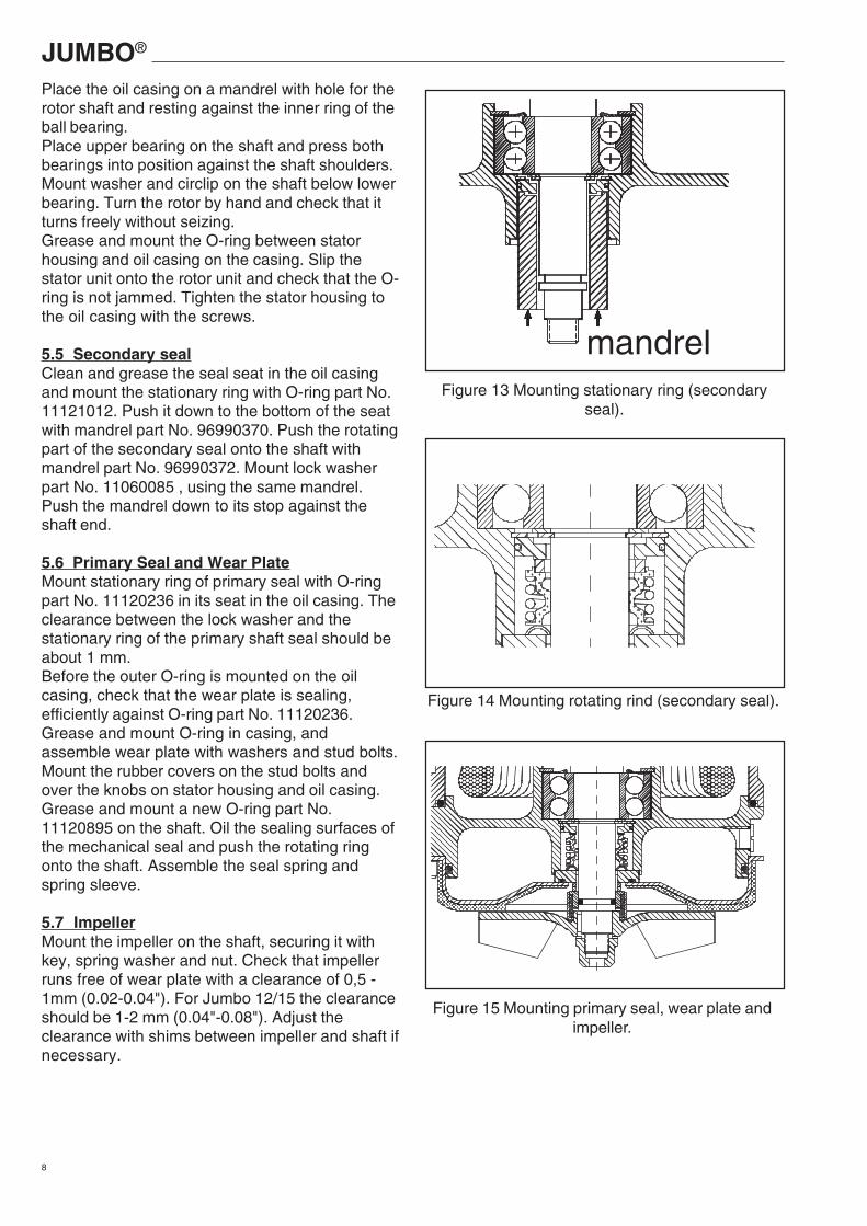
Place the oil casing on a mandrel with hole for therotor shaft and resting against the inner ring of theball bearing.Place upper bearing on the shaft and press bothbearings into position against the shaft shoulders.Mount washer and circlip on the shaft below lowerbearing. Turn the rotor by hand and check that itturns freely without seizing.Grease and mount the O-ring between statorhousing and oil casing on the casing. Slip thestator unit onto the rotor unit and check that the O-ring is not jammed. Tighten the stator housing tothe oil casing with the screws.
5.5 Secondary sealClean and grease the seal seat in the oil casingand mount the stationary ring with O-ring part No.11121012. Push it down to the bottom of the seatwith mandrel part No. 96990370. Push the rotatingpart of the secondary seal onto the shaft withmandrel part No. 96990372. Mount lock washerpart No. 11060085 , using the same mandrel.Push the mandrel down to its stop against theshaft end.
5.6 Primary Seal and Wear PlateMount stationary ring of primary seal with O-ringpart No. 11120236 in its seat in the oil casing. Theclearance between the lock washer and thestationary ring of the primary shaft seal should beabout 1 mm.Before the outer O-ring is mounted on the oilcasing, check that the wear plate is sealing,efficiently against O-ring part No. 11120236.Grease and mount O-ring in casing, andassemble wear plate with washers and stud bolts.Mount the rubber covers on the stud bolts andover the knobs on stator housing and oil casing.Grease and mount a new O-ring part No.11120895 on the shaft. Oil the sealing surfaces ofthe mechanical seal and push the rotating ringonto the shaft. Assemble the seal spring andspring sleeve.
5.7 ImpellerMount the impeller on the shaft, securing it withkey, spring washer and nut. Check that impellerruns free of wear plate with a clearance of 0,5 -1mm (0.02-0.04"). For Jumbo 12/15 the clearanceshould be 1-2 mm (0.04"-0.08"). Adjust theclearance with shims between impeller and shaft ifnecessary.
Figure 13 Mounting stationary ring (secondaryseal).
Figure 14 Mounting rotating rind (secondary seal).
Figure 15 Mounting primary seal, wear plate andimpeller.
JUMBO®
9
oil
oil
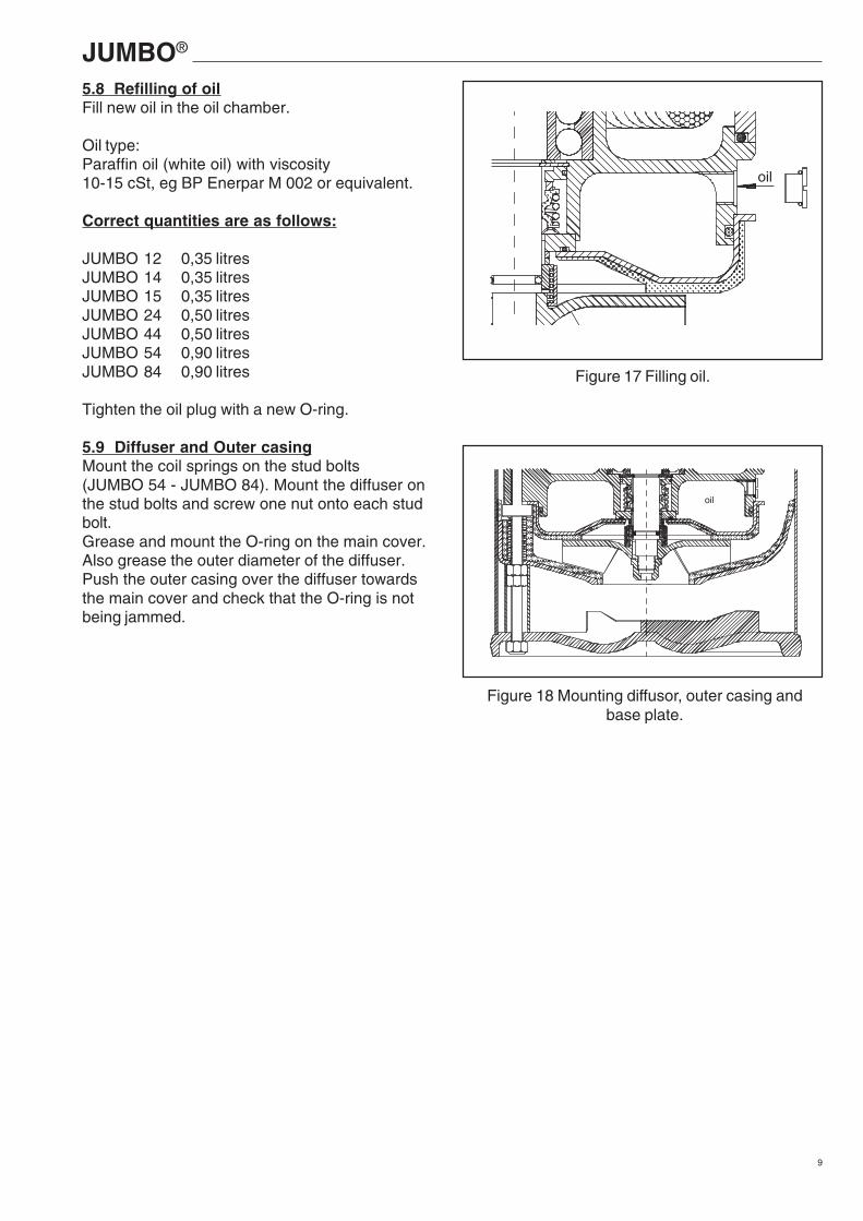
5.8 Refilling of oilFill new oil in the oil chamber.
Oil type:Paraffin oil (white oil) with viscosity10-15 cSt, eg BP Enerpar M 002 or equivalent.
Correct quantities are as follows:
JUMBO 12 0,35 litresJUMBO 14 0,35 litresJUMBO 15 0,35 litresJUMBO 24 0,50 litresJUMBO 44 0,50 litresJUMBO 54 0,90 litresJUMBO 84 0,90 litres
Tighten the oil plug with a new O-ring.
5.9 Diffuser and Outer casingMount the coil springs on the stud bolts(JUMBO 54 - JUMBO 84). Mount the diffuser onthe stud bolts and screw one nut onto each studbolt.Grease and mount the O-ring on the main cover.Also grease the outer diameter of the diffuser.Push the outer casing over the diffuser towardsthe main cover and check that the O-ring is notbeing jammed.
Figure 17 Filling oil.
Figure 18 Mounting diffusor, outer casing andbase plate.
JUMBO®
10
914
504
521
1106
1107
1105
1133
505
1137
502
116
1036
1037
1014
1012
1013
930
1118
1117
11251126
1114
1113
1102
DOL 1160
1078
1079
1019
60111111104
1170
1101
10151016
1018
102
910
1002
905901
219
151
908
237
232
213
219
208
102103
150108
233
204
143
229
235
236
228
206
228
201
214
222
1006
1004
1005
1011
1009
1024
1023
1020
1081
1074
YD 1103
102
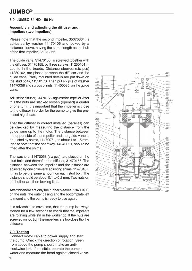
6.0 JUMBO 84 HD - 50 Hz
Assembly and adjusting the diffuser andimpellers (two impellers).
Please note that the second impeller, 35070364, isad-justed by washer 11470106 and locked by adistance sleeve, having the same length as the hubof the first impeller, 35070366.
The guide vane, 31470158, is screwed together withthe diffuser, 31470155, by three screws, 11250101, +Loctite in the treads. Distance sleeves (six pcs)41380102, are placed between the diffusor and theguide vane. Partly mounted details are put down onthe stud bolts, 11350170. Then put six pcs of washer11470058 and six pcs of nuts, 11400085, on the guidevane.
Adjust the diffuser, 31470155, against the impeller. Afterthis the nuts are slacked loosen (opened) a quaterof one turn. It is important that the impeller is closeto the diffuser in order for the pump to give the pro-mised high head.
That the diffuser is correct installed (parallell) canbe checked by measuring the distance from theguide vane up to the motor. The distance betweenthe upper side of the impeller and the guide vane isad-justed by shims, 11470071, to about 1 to 1,5 mm.Please note that the shaft key, 14040051, should befitted after the shims.
The washers, 11470058 (six pcs), are placed on thestud bolts and thereafter the diffuser, 31470156. Thedistance between the impeller and the diffuser areadjusted by one or several adjusting shims, 11470107.It has to be the same amount on each stud bolt. Thedistance should be about 0,1 to 0,2 mm. Two nuts oneachother are then locking it all.
After this there are only the rubber sleeves, 13400183,on the nuts, the outer casing and the bottomplate leftto mount and the pump is ready to use again.
It is advisable, to save time, that the pump is alwaysstarted for a few seconds to check that the impellersare rotating while still in the workshop. If the nuts arescrewed on too tight the impellers are too close tho thediffusers.
7.0 TestingConnect motor cable to power supply and startthe pump. Check the direction of rotation. Seenfrom above the pump should make an anti-clockwise jerk. If possible, operate the pump inwater and measure the head against closed valve.
JUMBO®
11
F0 F1
(of ten)
F1F0V2W2U2W1V1U1
YellowGreen/
Motor
Thermal contacts
Terminal board
Cable 9-leads
Star-delta starter
BLU
E
BLA
CK
GR
EY
(G
RE
EN
)
YE
LLO
W
BR
OW
N
RE
D
V2U2 W2W1V1U1
EC
BE
Aux
iliar
y
L1
L1N
C
Mai
n
G
230 VOption
G
C
E
B
WHITE
BLUE
RED
BLACK
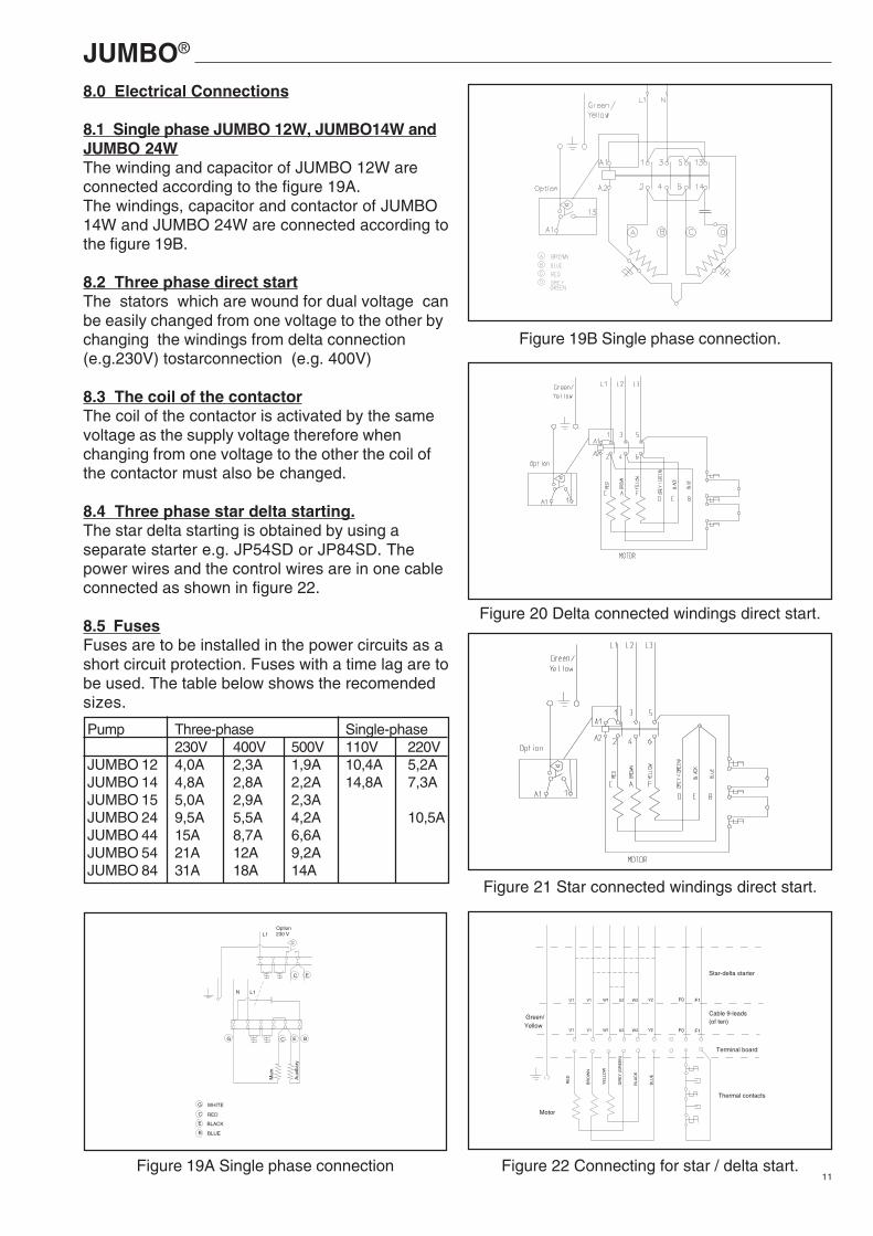
8.0 Electrical Connections
8.1 Single phase JUMBO 12W, JUMBO14W andJUMBO 24WThe winding and capacitor of JUMBO 12W areconnected according to the figure 19A.The windings, capacitor and contactor of JUMBO14W and JUMBO 24W are connected according tothe figure 19B.
8.2 Three phase direct startThe stators which are wound for dual voltage canbe easily changed from one voltage to the other bychanging the windings from delta connection(e.g.230V) tostarconnection (e.g. 400V)
8.3 The coil of the contactorThe coil of the contactor is activated by the samevoltage as the supply voltage therefore whenchanging from one voltage to the other the coil ofthe contactor must also be changed.
8.4 Three phase star delta starting.The star delta starting is obtained by using aseparate starter e.g. JP54SD or JP84SD. Thepower wires and the control wires are in one cableconnected as shown in figure 22.
8.5 FusesFuses are to be installed in the power circuits as ashort circuit protection. Fuses with a time lag are tobe used. The table below shows the recomendedsizes.
Figure 19B Single phase connection.
Figure 20 Delta connected windings direct start.
Figure 21 Star connected windings direct start.
Figure 22 Connecting for star / delta start.Figure 19A Single phase connection
Pump Three-phase Single-phase230V 400V 500V 110V 220V
JUMBO 12 4,0A 2,3A 1,9A 10,4A 5,2AJUMBO 14 4,8A 2,8A 2,2A 14,8A 7,3AJUMBO 15 5,0A 2,9A 2,3AJUMBO 24 9,5A 5,5A 4,2A 10,5AJUMBO 44 15A 8,7A 6,6AJUMBO 54 21A 12A 9,2AJUMBO 84 31A 18A 14A
JUMBO®
12
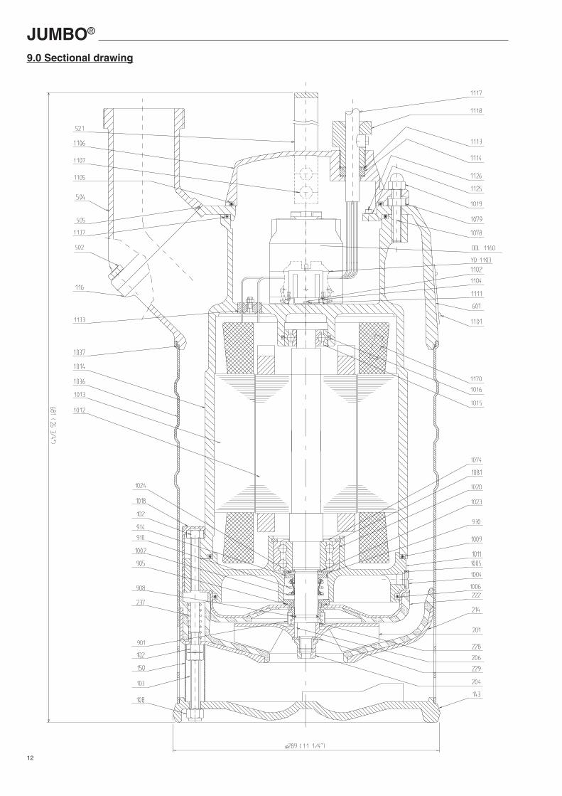
9.0 Sectional drawing