Embed Size (px)
Citation preview

June 27, 1995 Version 1.05
Copyright Kayeness Inc. 1995

1
_______________________________________________________________ 1
Galaxy I Melt Indexer User Manual
Version 1.05 Copyright Kayeness Inc. 1995
2
_______________________________________________________________ 2
TABLE OF CONTENTS About KAYENESS Inc. ..............................................................................................................5 How to Use this Manual ..............................................................................................................5 Typographic Conventions............................................................................................................5 How to Contact Kayeness Inc......................................................................................................6 Model Descriptions......................................................................................................................6
Model 7049 ...................................................................................................................7 Model 7050/7051 ..........................................................................................................7 Model 7053 ...................................................................................................................7 Model 7054 ...................................................................................................................7 Method B Encoder Option ............................................................................................7
Uncrating and Setup ....................................................................................................................8 Unpacking the Indexer ..................................................................................................8 Bench Requirements and Placement .............................................................................8 Level the Melt Indexer ..................................................................................................8 RTD Connection ...........................................................................................................9 Power Cord....................................................................................................................9 Printer Connection.........................................................................................................9 Computer Connection....................................................................................................9 Power Cleaning Tool.....................................................................................................9 Muffler installation........................................................................................................11 Software installation......................................................................................................11 Turning on the Indexer for the First Time.....................................................................12 Firmware Defaults .........................................................................................................13
SAFETY ......................................................................................................................................14 Use gloves its HOT! ......................................................................................................14 Electrical Hazard ...........................................................................................................14 Calibration Thermometers use Mercury........................................................................14 Pinch Points...................................................................................................................15 Don't Remove the RTD .................................................................................................15 Fumes from Materials....................................................................................................15 Pre-Test Safety Check ...................................................................................................16
Method "A" Run..........................................................................................................................20 General Description.......................................................................................................20 Calculations: Method A.................................................................................................20 Programming Details: Method A ..................................................................................20 How to do it: Step by Step.............................................................................................21
Machine Setup.................................................................................................21 Loading the Barrel ..........................................................................................22 Making the Cut................................................................................................23 Cleaning Up ....................................................................................................23 Cleaning Up a really Big Mess .......................................................................24
Method "B" Run ..........................................................................................................................25 General Description.......................................................................................................25 Calculations : Method B................................................................................................25 Programming Details: Method B...................................................................................26
Choosing a Timing Flag..................................................................................28 How to do it: Step by Step............................................................................................28
Machine Setup.................................................................................................28 Loading the Barrel ..........................................................................................29
3
_______________________________________________________________ 3
Inserting the Timing Flag and Starting the Run..................................................................................................................29 Cleaning Up ....................................................................................................30
Method "A/B" Run ......................................................................................................................32 General Description.......................................................................................................32 Calculations : Method A/B............................................................................................32 Programming Details: Method A/B...............................................................................32 How to do it: Step by Step.............................................................................................33
Instrument Setup .............................................................................................33 Loading the Barrel ..........................................................................................33 Inserting the Timing Flag................................................................................34 Making the Cut................................................................................................35 Cleaning Up ....................................................................................................35
Charge Weight.............................................................................................................................36 Kayeness In-house Standard Operating Procedure......................................................................37 Generic Run Check List...............................................................................................................39 Using theDigital Encoder ............................................................................................................40
To Test Encoder System:...............................................................................................40 To Calibrate/ReHome Encoder Position: ......................................................................40 Running Encoder Tests: ................................................................................................40 Mode Selection:.............................................................................................................41
MANUAL Mode Programming......................................................................41 AUTOMATIC Mode Programming................................................................41 Digital Encoder Run Tests ..............................................................................42 General Operating Notes:................................................................................42
Multiple Method B using the Digital Encoder.............................................................................43 Flow Rate Ratio test and the Pneumatic Lift Option ...................................................................43 Calculating I.V. from the Melt Indexer .......................................................................................44
Background and General Description ...........................................................................44 Daily ............................................................................................................................................47 Weekly.........................................................................................................................................47 Long Term ...................................................................................................................................47
Electronics .....................................................................................................................47 Temperature Calibration................................................................................................47 Die Dimensional Checks ...............................................................................................49 Check Optical Eye.........................................................................................................50 Digital Encoder Calibration...........................................................................................50 Mini Lift Installation .....................................................................................................54
Fixing a Thermometer when the Mercury has separated.............................................................57 Installing a new EPROM (firmware)...........................................................................................59 Temperature fluctuates ................................................................................................................61 Replacing your RAM chip...........................................................................................................61 Accuracy and Reproducibility .....................................................................................................64 Barrel Drawing ............................................................................................................................64 Conversion Factors (Viscosity, Temp) ........................................................................................65 Support Vendors ..........................................................................................................................65 Appendix: IV Option, Autoraise feature MSDS Sheets - Mercury
4
_______________________________________________________________ 4
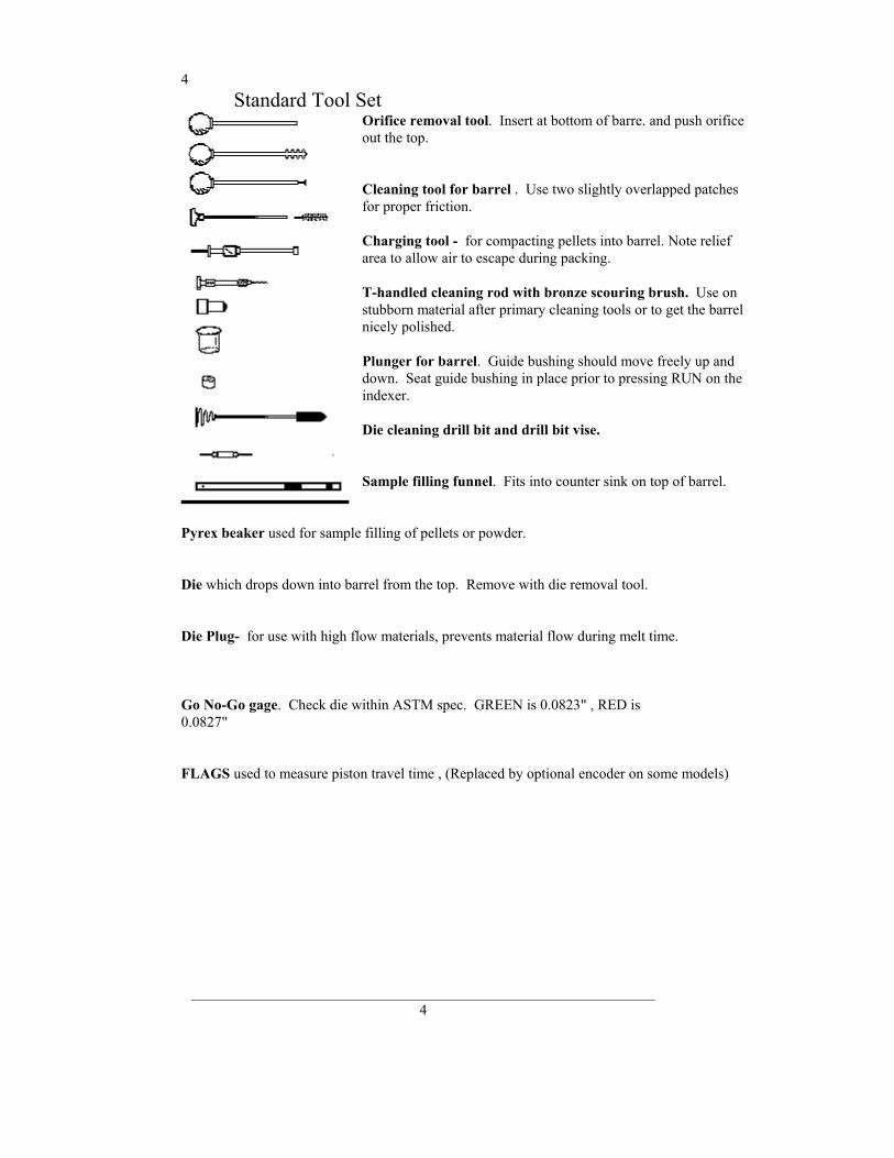
Standard Tool Set Orifice removal tool. Insert at bottom of barre. and push orifice out the top. Cleaning tool for barrel . Use two slightly overlapped patches for proper friction. Charging tool - for compacting pellets into barrel. Note relief area to allow air to escape during packing. T-handled cleaning rod with bronze scouring brush. Use on stubborn material after primary cleaning tools or to get the barrel nicely polished. Plunger for barrel. Guide bushing should move freely up and down. Seat guide bushing in place prior to pressing RUN on the indexer. Die cleaning drill bit and drill bit vise. Sample filling funnel. Fits into counter sink on top of barrel.
Pyrex beaker used for sample filling of pellets or powder. Die which drops down into barrel from the top. Remove with die removal tool. Die Plug- for use with high flow materials, prevents material flow during melt time.
Go No-Go gage. Check die within ASTM spec. GREEN is 0.0823" , RED is 0.0827"
FLAGS used to measure piston travel time , (Replaced by optional encoder on some models)
5
_______________________________________________________________ 5
Introduction About KAYENESS Inc. Kayeness is a manufacturer of laboratory test equipment supplying capillary rheometers, melt indexers, a variety of impact testers, coefficient of friction testers, contact angle testers, film tensile testers and other small test devices. Through its innovative work with electronics and mechanical design, Kayeness has carved a niche in the market place by providing the highest performance/cost ratio in the business. The company was founded in the late '60's in Honey Brook PA., and is built on two principles: quality workmanship and outstanding service. Kayeness' mission has grown to meeting the physical testing needs of the plastics, food, and rubber industries by providing high quality equipment and services at low cost. The company was purchased in 1988 by Dynisco, and is now a wholly owned subsidiary of Dynisco Inc. Dynisco, an ISO 9002 qualified supplier, is the worlds largest manufacturer of pressure transducers and is located in Sharon, MA.
How to Use this Manual This manual describes the setup procedure and basic operation of the Kayeness Galaxy class indexers. With the accompanying MIWORKS software manual (if software was purchased) it provides the complete description of resources at your command. It is not necessary to read this manual in its entirety; however, even experienced rheologists and technicians can benefit from the SAFETY tips and cleaning suggestions learned over many years of operating these instruments in our applications laboratory. The Getting Started Chapter explains the details of setting up the instrument, important safety issues and walks you through two standard tests. Experienced users may wish to skip over the initial runs if familiar with entering programs into the indexer.
Typographic Conventions Italics : Rheological items which have defining equations presented in the manual are shown in italics. If you come across an italicized item which is unclear you can be sure it has a mathematical definition previously defined in the manual. Bold Italics : These are parameters which are set from the front panel on the indexer (i.e. Melt Time, Mtd A Time etc.). These parameters are entered into the indexer's control programs via the indexer key pad. BOLD ALL CAPITALS : This indicates an actual key found on the indexer key pad. Example: Press the RESET button to return to main screen. Underlined Items : Underlined items head paragraphs or sections which pertain to the particular item or model underlined. If you do not have or are not interested in the underlined item skip the section that follows it. Underlining is also used to emphasize safety issues.
6
_______________________________________________________________ 6
How to Contact Kayeness Inc. Before calling Kayeness be sure you have gone through the "Answers to common questions" section (page 63) of the manual. To help us handle your questions as quickly as possible, have the following items ready before you call:
• Machine name and model number • Machine serial number (on back panel) • Current version of firmware (press RESET to see) • Computer system make and model • Current version of software (if applicable)
Call Kayeness directly at (610) 286-7555 and ask for technical support. Should you wish to comment or query in writing address it to: Kayeness Inc. : Customer Service 115 Thousand Oaks Blvd., POB 709 Morgantown, PA 19543 You can also reach us through compuserve ID's 73537, 644 or 73642, 1405 Model Descriptions The KAYENESS GALAXY I Series Melt Flow Indexer incorporates the latest in micro-electronic technology. It is designed to make melt flow rate testing faster, more accurate and flexible, and generate more rheological information. The heart of the system is a computer developed by KAYENESS. It controls temperature, responds to keyboard commands and implements testing programs. This system permits:
• Communications with larger computers • Direct output to printer • Stores test conditions in program memory • Shows instantaneous flow rate read-out • Battery backed-up date & test conditions • Download to MS-DOS compatible systems • Methods A, B, or A/B conversion and flow rate ratio • Automation purge or weight lowering • Control temperature within 0.1°C. • Automatic check of RTD sensor probe and over temperature alarm.

7
_______________________________________________________________ 7
Model 7049
This is the entry level machine. It will conduct method A tests only and can not be upgraded. Model 7050/7051 This model melt flow indexer does Method A, Method B and flow rate ratio testing. Temperature and flow rate are displayed on the instrument front panel. It has a 5 program memory. The unit can be upgraded to higher models. Model 7053 This model contains additional program capacity and can retain up to 20 test programs. In addition, it communicates with printers and can provide a series of more advanced technical information such as shear rate, shear stress, viscosity, with statistics on flow rate and viscosity which can be averaged over replicated tests. With the addition of the encoder option 10 complete test programs can be stored. Model 7054 The 7054 is the most sophisticated GALAXY Model available. It has all of the capabilities of the 7050, 7051, and 7053 and will communicate with other computers and can be multiplexed (8 machines to one PC). With the addition of the encoder option 10 complete test programs (set ups) can be stored. Method B Encoder Option The Kayeness Encoder for Method B tests employs a 1016 count optical encoder coupled to high accuracy gears to measure the piston travel. The optical encoder has dual outputs, enabling the signal to be processed in quadrature, yielding a resolution of 0.015mm. The linear distance of the piston is transferred to rotary displacement via a precisely calibrated arm. The tip of this arm employs a hardened & ground tip for extra long life. Accuracy over the ASTM measurement range of 0.25" and 1.00" is +/-0.001".The optical encoder, while being very accurate, also enables the test length signal to be processed & varied digitally. Thus, any test length up to 1"(ASTM) or 30mm (ISO) may be selected. Up to 15 MFR results per barrel filling can be obtained. The unit is securely fastened to the rear of the Melt Indexer, and the arm latches down to facilitate cleaning of the unit after the test is completed.
Encoder Advantages:
Completely Automatic Test Length Selection on Single MFR Tests Up to 15 MFR readings per Barrel Filling Any test length ("Flag") up to 30mm User Defined test length & test spacing for single or multiple tests Automatic Test Length & Test Spacing for multiple tests Ten test conditions stored internally
8
_______________________________________________________________ 8
Getting Started
Uncrating and Setup Unpacking the Indexer The KAYENESS Melt Flow Indexer comes in a heavy duty, double-walled cardboard container. First, open the main box and remove the instrument. Several boxes will also arrive by UPS; check that all boxes are received. They are coded 1 of 5 or 3 of 5, indicating the total number is five. It is recommended that the shipping carton be saved a few days until you are certain the machine works as expected. Bench Requirements and Placement Typical laboratory benches are too high for efficient use of the indexers. Cleaning can be difficult and requires awkward hand positions and forces which could lead to carpal tunnel syndrome or back discomfort. We strongly suggest a bench height of 29 inches (desk top height) for an average height operator. Place the front of the indexer flush with the edge of the table. This will prevent the operator from having to bend forward excessively when cleaning the barrel and allow easier access to the back of the machine. As a minimum, the lab bench should easily be able to support the indexer and operator (total approx. 300 lbs.). KAYENESS recommends placing from left to right, if purchased, the melt indexer; printer; computer. Test shake the melt indexer for stability. The bench top should also be able to withstand hot dies and tools being dropped on them. Carpet protection is necessary near the indexer since a hot die dropped on the carpet will quickly burn spots in it. Adequate ventilation will also be required to remove potentially harmful fumes from samples being tested. Consult the Material Safety Data Sheets (MSDS) on the products to be tested and your material supplier to assess the magnitude of your ventilation needs. You may wish to consider these ventilation needs when positioning the instrument in the laboratory. Most of the machine comes pre-assembled to your door, however certain parts are prone to breakage if they were placed in their normal operating position during shipping. These items will need to be installed before safe operation of the machine is possible. Other issues important to getting accurate data must also be addressed before valid testing can begin. Level the Melt Indexer Using the small round bubble level, supplied, level the melt indexer. Place the level on top of a COLD barrel and using the adjustable screw feet bring the machine into level. Tighten the locking nuts to keep the feet in level position Test shake the melt indexer for stability. Some companies bolt the machines directly to their benches. Be sure to remove the level before turning on the machine. The level will be damaged if it gets hot.
9
_______________________________________________________________ 9
RTD Connection There is a small (1" x 1" x 2") stainless steel cover over the two holes on the top of the instrument. Place the Resistance Temperature Detector (RTD) into the rear hole. To insert, swing the cover aside and insert the RTD, taking care not to break the ceramic insulation at the top of the RTD. The RTD has a red plug which should be placed into the red receptacle on the back of the instrument (near the top). The RTD's and associated temperature control electronics are calibrated against NIST traceable temperature probes at Kayeness. To achieve accuracy required by ASTM D1238 the RTD and electronics control should be kept together. Changing a RTD requires a complete temperature re-calibration. Power Cord Connect the power cord to the melt indexer. There may be a number of standard power cords supplied; the heaviest is used for the melt indexer. All power cords should be connected to electricity through the supplied 120V Wire-Tree Plus filter unit. Printer Connection Connect the printer (if you have one) to the melt indexer. A cable is provided with two distinctly different ends; one connects to the printer and the other to the melt indexer. The connections are on the back sides of both machines. Be sure the printer is OFF when connecting the the indexer. Computer Connection The data processing system (7054 models only) consists of a PC and the MIWORKS software package . If your melt indexer is so configured, one will notice that the link between the PC serial communications port (COM 1) and the indexer is made via a DB9 on the PC side to a round AMP connector on the indexer side. Connect the PC COM1 line to the 9 pin round amp connector on the back left side of the indexer. In this configuration, the printer is connected to the computer, not the melt indexer.. Alternatively the printer can be connected to both the computer and melt indexer through an parallel A/B switch box. In this case, the cable to the melt indexer is then taken off and connected to the A/B Box slot marked "COM". The computer and melt indexer are connected to this box with the two remaining cables as described above, with one being connected to "A" and the other to "B". Multiplexing If multiple machines are to be connected each indexer cable will run to a automatic switching box then a single cable will run from the switching box to the PC.
Power Cleaning Tool The optional power cleaning tool is a reversible drill with a steel shaft topped with a knurled aluminum cap to hold patches. This is a battery powered unit that makes cleaning much easier. It comes with a rechargeable battery and charging unit and lasts about a week per charge in your average laboratory. Part # 8052-97K
10
_______________________________________________________________ 10
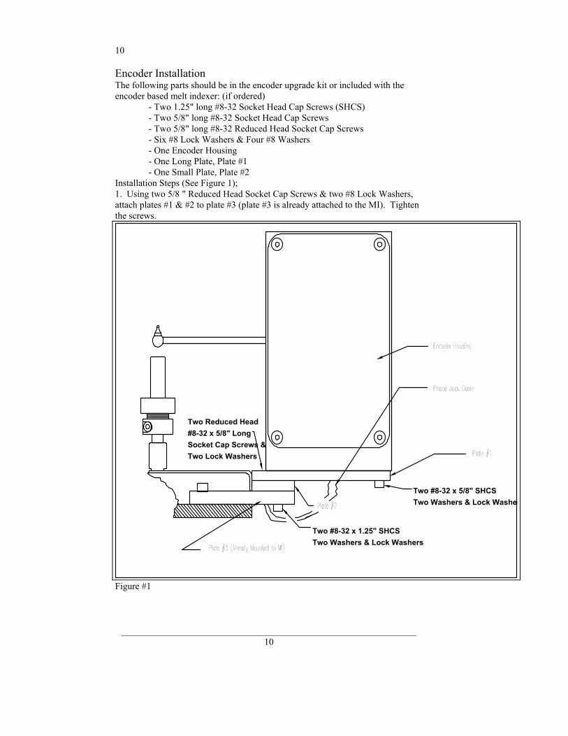
Encoder Installation The following parts should be in the encoder upgrade kit or included with the encoder based melt indexer: (if ordered) - Two 1.25" long #8-32 Socket Head Cap Screws (SHCS) - Two 5/8" long #8-32 Socket Head Cap Screws - Two 5/8" long #8-32 Reduced Head Socket Cap Screws - Six #8 Lock Washers & Four #8 Washers - One Encoder Housing - One Long Plate, Plate #1 - One Small Plate, Plate #2 Installation Steps (See Figure 1); 1. Using two 5/8 " Reduced Head Socket Cap Screws & two #8 Lock Washers, attach plates #1 & #2 to plate #3 (plate #3 is already attached to the MI). Tighten the screws.
Figure #1
Two #8-32 x 5/8" SHCS
Two Washers & Lock Washers
Two Reduced Head#8-32 x 5/8" LongSocket Cap Screws &Two Lock Washers
Two #8-32 x 1.25" SHCS
Two Washers & Lock Washer
11
_______________________________________________________________ 11
2. Attach the Encoder Housing to the long plate (plate #1) using two 1.25" long SHCS, two 5/8" long SHCS, 4 washers & 4 lock washers (washers first then lock washers, i.e. lock washers under screw head).
Note for Pneumatic Lift Users: With the encoder arm in the down position, lower the pneumatic lift. Move the arm up and down to check for clearance with the pneumatic lift bucket. Clearance may be increased a small amount by rotating the encoder housing before tightening the screws. If no clearance exists and the arm hits the pneumatic lift bucket, contact Kayeness before proceeding.
Tighten the screws.3. Plug the phone jack cable into the encoder housing. 4. Move the arm down into the détente position 5. Turn power on 6. Press TEST on the front panel. Press YES to answer the question Encoder Test? whcih appears on the LED display. Verify that the encoder is functioning by moving the encoder arm up and down and observe that the encoder position displayed changes with movement of the encoder arm. 7. See page 40 for detailed instructions on the variety of uses and programming available with the encoder option. Muffler installation Indexers which have only one lift mechanism have the mufflers installed at the factory. If you have purchased both the main pneumatic lift system (hold 21.6 kg mass) and the mini lift (piston and weight support) the mufflers are not installed since they may break during shipment. Only if you have purchased both the main pneumatic lift system (hold 21.6 kg mass) and the mini lift (piston and weight support) do you need to install the mufflers. WARNING! MUFFLERS MUST BE INSTALLED BEFORE OPERATING THE INSTRUMENT! Screw one muffler into each pneumatic solenoid (one for the pneumatic lift and one for the mini lift). The solenoids are located in the rear of the Melt Indexer and are mounted one on each side of the base plate. The correct solenoid port faces outward and has been taped over. Remove the tape and screw the muffler into the solenoid. Software installation If you purchased your PC from Kayeness the software should already be installed on your computer. If you have accidentally erased the program or have purchased your own computer with the indexer system, insert the MIWORKS floppy diskette in drive a: then type a:install. MIWORKS will then install itself onto the hard drive C: creating the directory path c:\MIWORKS if it does not exist. If the install routine finds an existing directory it will only delete the main MIWORKS program replacing it with the current version on the floppy. It may add additional example files to those that exist. No data directories nor data files in the c:\MIWORKS directory will be deleted. Should you wish to save the current version of MIWORKS perform the following steps prior to installation or re-installation from floppy.
12
_______________________________________________________________ 12
c: cd\miworks rename miworks.exe miworksA.exe To run the old version of MIWORKS simply type MIWORKSA to start the old MIWORKS program. Turning on the Indexer for the First Time 1. Be sure you have leveled the machine on the workbench and connected the
RTD (Page 9) before proceeding. 2. Clean the Barrel. The indexer barrel leaves the factory coated with oil to
protect it from rust. This oil must be removed before accurate rheological data can be obtained. Put two cotton patches half overlapped directly over the top of the barrel of the still cold machine. Use indexer cleaning tool #4 pictured on page 10 to run the patches up and down the full length of the barrel. Repeat the process with fresh patches until the patches come out clean. Note: often the first four or five runs are invalid due to a slight presence of machining oil in the barrel.
3. Check the orifice with the green end of the "Go-No GO" gage. (Note: all
dimensional checks are to be done when the part to be checked is at room temperature.) If it does not go through, use the orifice cleaning brush to remove any residual oils, burned or degraded polymer and try again. If it passes, drop the orifice down into the barrel.
4. Check that the piston tip is screwed on tightly to the piston rod. No space
should appear between the tip and the piston rod. Remember, clockwise tightens, so always wipe it clockwise when cleaning. Then place the piston rod into the heat chamber.
5. Put the electrical plug into a 120 V A.C., 10 amp, grounded outlet. The
power switch is on the back right hand side of the indexer. If you have a pneumatic lift you will hear a puff of air as you turn on the machine; this is normal, don't let it startle you. The top digital display will briefly show the temperature we wish to maintain (set point) then switch to actual reading from the temperature probe in the barrel. The lower part of the red LED display will briefly show KAYENESS, then the name and version number of the software. It then reverts to showing "WAIT" along with the program number and the test mode, (A, B, or A/B). The "WAIT" indicates that set temperature has not "locked in".
Note: If alarms sound and top display reads "E001" turn off the instrument
and check the RTD connection (Page 9). IF NOTHING HAPPENS If these things don't happen, unplug the instrument and remove the two
screws toward the back and on each side of the instrument's cover. The cover should swing up and forward to display the PC boards. Check that all PC boards are in place and that all connectors are firmly attached. If any appear loose push them in and try again. For your safety the top cover must be in place when power is re-connected. If there is still no display, call the factory (Page 6). Damage may have occurred in shipping.
13
_______________________________________________________________ 13
6. Set desired temperature by pressing EDIT then press the YES key repeatedly
until TEMP. XXX appears, where XXX is the current temperature set point. Press NO and the display reads TEMP. 000.0. Presss 2 3 0 then YES then RESET. 230 Celsius is now the new tempearture for the indexer. It typically requires about one-half hour to come up to temperature and find the set point during the initial lock-in for each new temperature; once locked-in subsequent start-ups will be much faster. A small dot comes on to the right of the temperature digits when lock-in has occurred. When lock-in occurs the unit sounds two beeps and the LED changes from "WAIT" to "READY". The machine will go out of lock when material is added to the machine or a cold piston rod is placed in the barrel this is normal.
7. Press SHIFT, then PRINT (but not simultaneously) to check the options
program. This checks the firmware settings settings to see if your hardware configuration is setup properly. Press YES if statisfied and move to the next item or press NO to toggle through options for that item.
8. If the KAYENESS Data Processing System MIWORKS is being used: turn
on the personal computer and monitor. The program will come up automatically as part of the systems start up. If not, refer to the MIWORKS manual for installation and troubleshooting.
Firmware Defaults Firmware is the programming embedded into computer chips (EPROMS etc.) found inside the indexer. The firmware governs most of the indexers behavior and all of its communications to outside devices like the PC or a directly connected printer. Software (like Miworks) runs on your PC and helps you save and analyze your data. When an indexer system is built, the firmware needs to know specific details about the machine in order to function properly. A lightening strike or major brownout has been known to change this code. If you notice problems after a power outage, call Kayeness immediately.
14
_______________________________________________________________ 14
SAFETY Use gloves its HOT! To prevent burns, gloves and a long sleeve shirt (or lab coat) are essential. Dies and piston rods are extremely hot and are designed to quickly transfer heat to the sample being tested. Unfortunately this means they will transfer heat very quickly to you as well. Even brief contact with a hot item can cause a burn. The indexer barrel housing can also get fairly hot, however at barrel temperatures lower than 350 °C these will not cause burns if touched for a brief period. Consider where dies may fall. If they are dropped on Nylon carpeting or similar materials they can quickly form holes. Protective mats may be needed. KAYENESS recommends keeping a hot piston rod in the chamber; this precludes someone picking it up inadvertently. Be sure to hold piston with the top insulator. Electrical Hazard Your Kayeness indexer contains high voltage inside the stainless steel base. When this steel cover is opened a plastic cover is revealed. The plastic shield aids in protecting you from these voltages. DO NOT remove this cover unless you are instructed to do so by a KAYENESS representative or are experienced with high voltage devices. There are holes cut in the shield which allow access to the necessary items used in routine calibrations. Be sure the outlet used to power the indexer is properly grounded. Calibration Thermometers use Mercury To calibrate the temperature on the indexer a thermometer containing about 8 grams of mercury is used. Every lab with mercury thermometers or equipment containing mercury must be prepared for breakage. Note that mercury exposed to air "evaporates" at room temperature, producing an invisible, tasteless, odorless and dangerous vapor. Thermometers have been used for decades in laboratory equipment and when used properly provide an accurate and effective means of calibration. Keep the thermometer in a safe place were it will not be crushed or otherwise broken. When using the thermometer be careful not to drop or bend the glass. Place a hot thermometer onto cotton patches to cool . Never put a hot thermometer in contact with cold metal or cold solvent because the thermal shock can crack or shatter the glass. Mercury is extremely toxic and should be handled accordingly. A material safety data sheet (MSDS) for mercury (Hg) can be found in the appendix. Observe local, state and federal hazardous waste disposal laws when disposing of any broken thermometers. You can find the names of mercury spill kit suppliers on page 62. If packaged in a sealed plastic container and labeled with the following symbol:
Broken thermometers and their spilled mercury can be sent back to the manufacturer. UPS will accept these packages provided they are labeled and the material is in a secure container. See Princo support vendor for address information.
15
_______________________________________________________________ 15
Pinch Points Do not place weights in precarious positions where they can be bumped and fall to the floor, perhaps crushing a finger or a toe. For large weights (over 10 kg) the pneumatic lift system is recommended. In using a pneumatic lift system for weights up to 21,600 gram, the safety pin (spike) that goes through the weights must be used. When the machine is in operation the lift system moves the weight downward quickly creating an area where anything lying beneath could get crushed. Press the UP and DN keys only when the areas above and below the weight are clear. Don't Remove the RTD The RTD is a 2-3 mm thin rectangular section of platinum wire grid which is used to measure the temperature. It is housed in a 4.75 mm (3/16") steel tube about 125 mm (5 inches) long with a 90 degree bend on one end. This tube is just to the left of the top of the indexer barrel under a protective metal shield. Don't remove the platinum resistance thermometer (RTD) UNLESS the set point temperature (Melt Temperature) has been set to zero (0.0). When the RTD is removed with the set point temperature higher than room temperature the machine senses cold and pumps more heat to the heaters. Excesive temperatures can ruin the heat treatment on the cylinder and supporting insulators.Always set the temperature to 0.0 before removing the RTD! If you are not calibrating, it is best to turn the machine off when removing the RTD. If you wish to check the temperature in the barrel use the front hole drilled just for the thermometer. There is an over-temperature alarm which is set for 315°C on a standard model (440 °C. on high temperature models). If a malfunction occurs, full heat may come on and this unit will sense it from the RTD signal and cut off the heater power. It will be inoperative until the temperature drops below over-temperature point. Fumes from Materials Plan for the unexpected when it comes to materials giving off hazardous vapors. Many polymers (PVC, PVF etc.) are well known for giving off hazardous fumes at elevated temperatures. An exhaust system which removes fumes from both the die exit and near the top of the barrel is strongly recommended. Consideration should also be given to additives which may degrade or decompose at elevated test temperatures.
16
_______________________________________________________________ 16
Pre-Test Safety Check
• 120V power outlet properly grounded? (220 V Europe/Asia) • RTD (temperature sensor) in barrel and connected? • Indexer level and on a sturdy bench? • Protective oil wiped out of barrel? • Exhaust hood or snorkel operational? • Arm protection, long sleeves or lab coat • Operator using high temp gloves? • Operator using safety glasses? Refer back to Page 8 if you need more information on the above items.
If you have not already done so bring the machine to 230C by pressing EDIT on the front panel of the indexer. Press YES until the word TEMP. = XXX will appear. Press 2 3 0 then YES; the top display should show 230 for a second or two then the current temperature will be displayed. You should see it rising slowly to 230 ºC. Purging the Barrel Once at 230 ºC the machine is sufficiently hot one can purge the instrument with Polyethylene (PE) or Polypropylene (PP). A purge is simply a charge of material run through the machine without collecting data. The purge run helps eliminate any remnants from previous tests. It also coats and fills micro cavities in the metals which can be a cause of variability. When switching material types or grades Kayeness recommends a purge be performed even when the barrel and die will be cleaned after the purge. Experiment and see if it matters for your materials. Use the 10 mL beaker to scoop a heaping beaker of pellets from the sample you wish to run. Get the filling funnel and place it directly over the top of the barrel. The lip on the base of the funnel will fit onto the top of the barrel insulator. Holding the funnel in your left hand gently pour about 2/3 of the pellets from the beaker into the funnel (you may need to tap the beaker against the funnel lightly). After putting in only 2/3 of the beaker content push the packing tool end directly into the funnel and firmly press the material down into the barrel. Push down until you feel no more movement downward. It is not necessary to use excessive force in packing. Try not to leave the packing tool in the barrel for too long. If the packing tool heats up material will melt around it and make packing difficult. Add the remaining material and pack it down as before. Place the plunger into the barrel giving it a twist clockwise (looking down from above the plunger) be sure the guide bushing slides down into the top part of the barrel. This guide bushing forces the plunger to feed into the barrel correctly. Let the material heat up for about 3 minutes or longer. Time is not critical here; we merely want to give the material enough time to melt so we don't hurt ourselves trying to push it out. Put a weight on the piston rod and push the material out.
17
_______________________________________________________________ 17
On Overview of MI A flow rate test is a measure of polymer's mass flow rate (grams extruded in 10 minutes) using a particular orifice under specified conditions of temperature and load. Machines which determine flow rate are in general called Melt Indexers. Test methods by ISO, DIN, ASTM and others specify heat chamber and piston tip diameter such that the shear stress on the polymer is the same in all machines for a given load. In addition, material specification guidelines (by ISO, DIN, ASTM, GM etc.) may exist which give further constraints on how a particular type of material may be run. The tests we are interested in performing are those described by ASTM D1238 and ISO 1133. This manual in no way supersedes either of these documents. The precision and accuracy of the test has been determined by ASTM and can be found in the back of method D1238. Contributing to both precision and accuracy are operator variances such as; packing technique, cleaning, cutting, weighing etc. With moisture sensitive polymers, dryness can also play a major roll, and time can be a factor with thermally unstable polymers, so procedures must be identical. Kayeness has have found that charging a consistent mass of material into the barrel (±0.1 grams) is the most critical factor is getting precise data. Two basic methods have been developed for running flowrate tests under D-1238, Methods A and B. Method A is simply the collection of extrudate over time, while Method B is the measurement of time for the flow of a fixed volume of polymer. Method A - the test is completely manual and is sometimes called the "cut-n-weigh" method. Method A/B - this employs the electronic eye or digital encoder. In order to run a method B test, an A/B run MUST be run first to determine the polymer's melt density Method B can be conducted only after an A/B experiment is conducted. This is a "no-cuts" test that is the most convenient for busy laboratories. The Key Pad Before proceeding further it is necessary to describe the function of the various keys on the front panel of the indexer. These keys will be used in the day-to-day operation of the machine. Try them and do not hesitate to experiment - one can always hit RESET to clear previous inputs and "start fresh". EDIT Used to create or change programs. After touching EDIT, the display asks questions. Every question requires a YES, NO or alphanumeric input from the operator. If the response is YES, it will proceed to the next question. If NO, it clears the current entry and either 1) waits for a value or 2) it displays another choice which can be accepted or rejected. Details are fully described under the individual test methods A,B and A/B.
18
_______________________________________________________________ 18
TEST Used for machine calibration. It shows RTD temperature to 0.01 resolution and indicates whether the optical eye is blocked or clear. Details of temperature and electronic eye calibration procedures can be found on Page 47 RESET Puts system back to the beginning of the program. If all changes have been completed during an editing session, pressing RESET will retain changes, but will exit user from running through the rest of the EDIT program mode. Additionally, RESET can be pressed at any time during a run to cancel the run. RUN After loading a sample RUN is pressed to initiate the test timing sequence. It is also pressed when the first cut is made on the extrudate undergoing a Method A test. PRGM This key (followed bythe number of selected program) permits entering five test program specifications. If selected, the machine test specifications and temperature will be automatically set to those stores in the program. Two digits are expected so it is important to enter the leading zero. Get program #5 by pressing PRGM 0 5
Plus (+) & Minus (-) When in EDIT + & - are used for alphanumeric
entries into Sample and Material ID. If you want a letter press "+" and an "A"
will show. If you continue to hit "+" it will progressively index one letter at a
time. Indexing down a letter is achieved with "-". Six letters may be skipped by
pressing SKIP. Once you arrive at your letter press YES and that letter will be
entered. If uses a number as part of the Material ID, they are entered directly
(YES does not have to be pushed). Once complete, press YES again and the
Sample ID is recorded.
MiniLift If the system is equipped with a minilift it can be activated up and down with the + & - keys respectively. The mini lift will function only when not in EDIT mode.
UP & DN Used to operate pneumatic lift manually. ` SHIFT Provides a double function for some keys. These keys should be pressed one at a time not together.
SHIFT - PRINT Contains the "Option program": FORM FEED? (YES or NO) Off means it skips three 3 lines between print-outs, on means it skips an entire page. PRINTER? (YES or NO) This controls transmit to a printer. It should be *NO if a printer is not used.
19
_______________________________________________________________ 19
DATA COMPUTER? (YES or NO) This controls transmit to a data processor. It must be *NO if not using a PC. *Press the YES key when display reads NO. Encoder (AUTO or MANUAL) This determines whether the flag lengths are determined automatically by the program or input manually by the user. SHIFT - NO Asks CLR ALL MEM? If YES is pressed the entire memory is erased and all programs must be re-entered. This is like reformating a P.C. disk.
DATE Enters time information into system running clock for the printer. By selecting DATE it will ask you the following questions: A. Year 0095=1995 B. Month 0009=September C. Date 0016=16th D. Day 0001=Sun, 0002=Mon E. Hour 0013= 1 PM F. Minute 0030= :30 PRINT When printer is connected to melt indexer, prints stored programs. The LED display responds with: PRINT ALL? Press YES for all programs, NO for only the current program. Remember you may terminate the total print program at any program number by hitting RESET. YES Accepts the currently display information into the test program. This is similar to ENTER on a P.C. NO Rejects the display value, clears display, and waits for correct value. END Completes a series of runs; if printer is available, averages, standard deviation, and coefficient of variance are calculated for viscosity and flow rate. ID Used to enter the sample and operator ID on the printout. This loop is separate from the EDIT loop in order that the basic program remains unchanged, but each sample run has a different label (e.g. notebook, lot, or batch number), and operator. SKIP Used in the alphanumeric mode with + & - keys. Allows the user to skip six letters at a time through the alphabet. DEL No function/undefined. (used on motor driven capillary rheometer)
20
_______________________________________________________________ 20
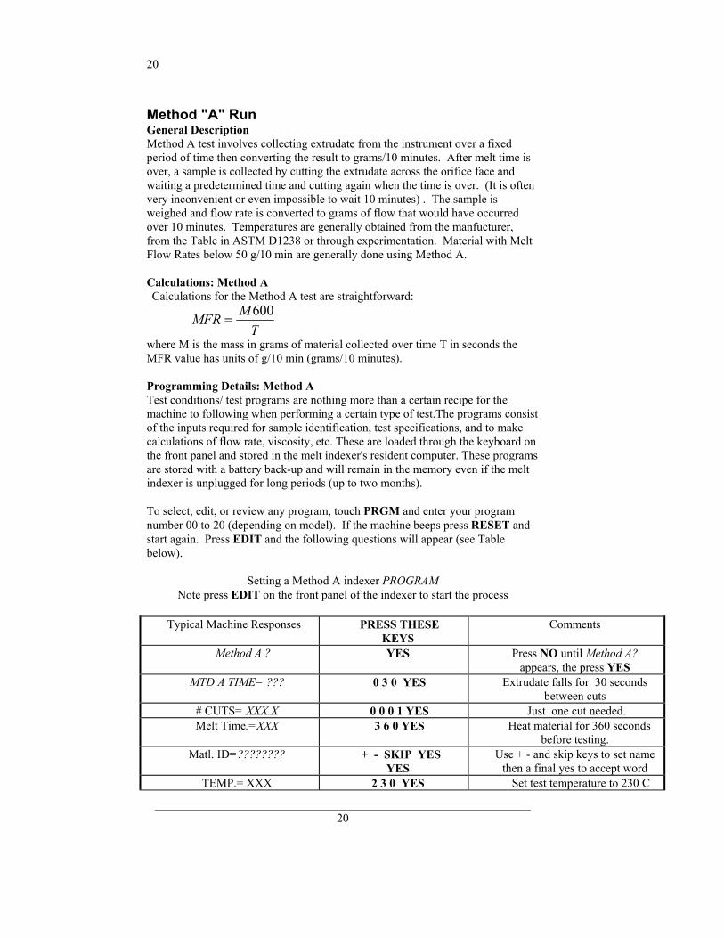
Method "A" Run General Description Method A test involves collecting extrudate from the instrument over a fixed period of time then converting the result to grams/10 minutes. After melt time is over, a sample is collected by cutting the extrudate across the orifice face and waiting a predetermined time and cutting again when the time is over. (It is often very inconvenient or even impossible to wait 10 minutes) . The sample is weighed and flow rate is converted to grams of flow that would have occurred over 10 minutes. Temperatures are generally obtained from the manfucturer, from the Table in ASTM D1238 or through experimentation. Material with Melt Flow Rates below 50 g/10 min are generally done using Method A. Calculations: Method A Calculations for the Method A test are straightforward:
MFR MT
= 600
where M is the mass in grams of material collected over time T in seconds the MFR value has units of g/10 min (grams/10 minutes). Programming Details: Method A Test conditions/ test programs are nothing more than a certain recipe for the machine to following when performing a certain type of test.The programs consist of the inputs required for sample identification, test specifications, and to make calculations of flow rate, viscosity, etc. These are loaded through the keyboard on the front panel and stored in the melt indexer's resident computer. These programs are stored with a battery back-up and will remain in the memory even if the melt indexer is unplugged for long periods (up to two months). To select, edit, or review any program, touch PRGM and enter your program number 00 to 20 (depending on model). If the machine beeps press RESET and start again. Press EDIT and the following questions will appear (see Table below).
Setting a Method A indexer PROGRAM
Note press EDIT on the front panel of the indexer to start the process
Typical Machine Responses PRESS THESE KEYS
Comments
Method A ? YES Press NO until Method A? appears, the press YES
MTD A TIME= ??? 0 3 0 YES Extrudate falls for 30 seconds between cuts
# CUTS= XXX.X 0 0 0 1 YES Just one cut needed. Melt Time.=XXX 3 6 0 YES Heat material for 360 seconds
before testing. Matl. ID=???????? + - SKIP YES
YES Use + - and skip keys to set name
then a final yes to accept word TEMP.= XXX 2 3 0 YES Set test temperature to 230 C
21
_______________________________________________________________ 21
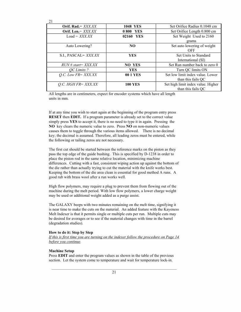
Orif. Rad.= XXX.XX 1048 YES Set Orifice Radius 0.1048 cm Orif. Len.= XXX.XX 0 800 YES Set Orifice Length 0.800 cm
Load = XXX.XX 02160 YES Set Weight Used to 2160 grams
Auto Lowering? NO Set auto lowering of weight OFF
S.I., PASCAL= XXX.XX YES Set Units to Standard International (SI)
RUN # start= XXX.XX NO YES Set Run number back to zero 0 QC Limits ? YES Turn QC limits ON
Q.C. Low FR= XXX.XX 00 1 YES Set low limit index value. Lower than this fails QC
Q.C. HGH FR= XXX.XX 100 YES Set high limit index value. Higher than this fails QC
All lengths are in centimeters, expect for encoder systems which have all length units in mm.
If at any time you wish to start again at the beginning of the program entry press RESET then EDIT. If a program parameter is already set to the correct value simply press YES to accept it, there is no need to type it in again. Pressing the NO key clears the numeric value to zero. Press NO on non-numeric values causes them to toggle through the various items allowed. There is no decimal key; the decimal is assumed. Therefore, all leading zeros must be entered, while the following or tailing zeros are not necessary. The first cut should be started between the reference marks on the piston as they pass the top edge of the guide bushing. This is specified by D-1238 in order to place the piston rod in the same relative location, minimizing machine differences. Cutting with a fast, consistent wiping action up against the bottom of the die rather than actually trying to cut the material with the knife works best. Keeping the bottom of the die area clean is essential for good method A runs. A good rub with brass wool after a run works well. High flow polymers, may require a plug to prevent them from flowing out of the machine during the melt period. With low flow polymers, a lower charge weight may be used or additional weight added as a purge assist. The GALAXY beeps with two minutes remaining on the melt time, signifying it is near time to make the cuts on the material. An added feature with the Kayeness Melt Indexer is that it permits single or multiple cuts per run. Multiple cuts may be desired for averages or to see if the material changes with time in the barrel (degradation studies). How to do it: Step by Step If this is first time you are turning on the indexer follow the procedure on Page 14 before you continue. Machine Setup Press EDIT and enter the program values as shown in the table of the previous section. Let the system come to temperature and wait for temperature lock-in.
22
_______________________________________________________________ 22
Lock-in has occurred when a small red dot appears to the right of the Temperature digits (e.g. 230 ) indicating the temperature is stable. (Note: the first lock-in for each new temperature takes approximately 1/2 to one hour, while subsequent lock-ins take considerably less time). Heat up and lock-in must occur with orifice and piston rod in the heat chamber. During heat up the program may be adjusted and the operator and sample ID can be entered by pressing the ID key, using + ,−, and SKIP as described in the KEY PAD section on Page Error! Bookmark not defined..
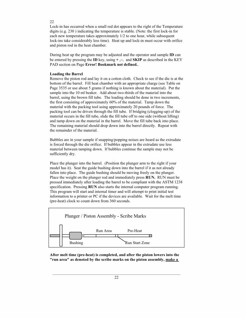
Loading the Barrel Remove the piston rod and lay it on a cotton cloth. Check to see if the die is at the bottom of the barrel. Fill heat chamber with an appropriate charge (see Table on Page 3535 or use about 5 grams if nothing is known about the material). Put the sample into the 10 ml beaker. Add about two-thirds of the material into the barrel, using the brown fill tube. The loading should be done in two increments, the first consisting of approximately 60% of the material. Tamp down the material with the packing tool using approximately 20 pounds of force. The packing tool can be driven through the fill tube. If bridging (clogging-up) of the material occurs in the fill tube, slide the fill tube off to one side (without lifting) and tamp down on the material in the barrel. Move the fill tube back into place. The remaining material should drop down into the barrel directly. Repeat with the remainder of the material. Bubbles are in your sample if snapping/popping noises are heard as the extrudate is forced through the die orifice. If bubbles appear in the extrudate use less material between tamping down. If bubbles continue the sample may not be sufficiently dry. Place the plunger into the barrel. (Position the plunger arm to the right if your model has it). Seat the guide bushing down into the barrel if it as not already fallen into place. The guide bushing should be moving freely on the plunger. Place the weight on the plunger rod and immediately press RUN. RUN must be pressed immediately after loading the barrel to be compliant with the ASTM 1238 specification. Pressing RUN also starts the internal computer program running. This program will start and internal timer and will attempt to print initial test information to a printer or PC if the devices are available. Wait for the melt time (pre-heat) clock to count down from 360 seconds.
After melt time (pre-heat) is completed, and after the piston lowers into the "run area" as denoted by the scribe marks on the piston assembly, make a
Run Area Pre-Heat
Plunger / Piston Assembly - Scribe Marks
Run Start ZoneBushing
23
_______________________________________________________________ 23
cut and press RUN simultaneously. If the sample extruded so fast that it has already passed the scribe marks you must take one of the follow options:
• Add more material • Reduce the test load (e.g. 2160 to 225 g) • Reduce the test temperature ( e.g 230 to 190 C) • Use a flow plug • Support the plunger and piston during melt time • Change to a non-standard die (e.g, 1/2 diameter, 1/2 height)
If the sample extrudate is so slow that you do not reach the first scribe mark before 8 minutes has expired you must take one of the following actions:
• Add less material • Increase the test load (e.g. 2160 to 21,600 g) • Increase the test temperature ( e.g 190 to 230 C) • Change to a non-standard die (typically larger diameter)
Making the Cut When the lower scribe mark on the plunger reaches the top of the guide bushing simultaneously cut the extrudate and press RUN. Use the cutting knife in a wiping like action up against the bottom of the die. After pressing RUN a count down timer appears on the left of the front display. As it counts down it will give a warning beep when 10 seconds remain. Exactly when it reaches zero and beeps cut the extrudate up against the bottom of the die, as before. Weigh the sample and enter the weight in grams using the touch panel and hit YES if correct. (A precison balance is needed in order to obtain precise flow rate measurements) The flow rate will be immediately calculated and displayed. A extrudate weight of about 1.0 gram or more will reduce weighing errors, adjust the cut time as needed to get at least 0.5 grams of material. If the indexer has printing capability, flow rate will be printed along with other test details. When multiple tests have been completed an average, standard deviation and coefficient of variance can be printed once, when the END key is pressed.
Cleaning Up Push down on the weight an purge any material remaining in the barrel. Remove the rod by twisting it clockwise to break the seal created by the molten plastic then pull straight up. Warning: If you pull the rod out too quickly you may cause a suction the pulls the die out along with it. Wipe the plunger rod with a cotton rag. Remove the die with the die removal tool and clean with the appropriate cleaning tools. Put two patches directly over the barrel about 1/2 way overlapped. Using the cleaning tool push the patch down into the barrel. Run the patch up and down a half dozen times or so, then repeat the process. The second set of patches should come out fairly clean, if not repeat the process until they come out clean. When done put the die and plunger back into the barrel. This allows the plunger and die to heat up before the next test.

24
_______________________________________________________________ 24
With materials that are thermally stable (less than 5% viscosity change over 1/2 hour) we recommend only cleaning the barrel between runs of the exact same material. For materials that degrades or are moisture sensitive we recommend cleaning both the barrel and the die completely. To clean the die use the die removal rod and push the die up from the bottom of the barrel and out the top. Wipe it with the cotton rag and clean it by running the drill bit through it several times. Remove material that collects in the grooves of the drill bit and repeat until the drill passes easily through the die. Scrape the die with the cutting knife if needed to clean the top and bottom faces. For materials that crystallize quickly you can clean the die by first running a drill bit up into the die while it is hot and in the indexer. This will make it much easier to get the cleaning drill bit in when the die is removed and the material starts to solidify. While the die is out, put on safety glasses and look down the barrel bore to be sure it is clean. A clean barrel will have a mirror-like shine to it. If it is not run a couple of patches up and down it before putting the die back into position. User Tip: drop the die into the barrel and listen for the double bounce of the die when as it falls back into the barrel. If the barrel is dirty, the die hangs up and will not bounce when it hits the bottom of the barrel. User Tip:If you are using a PVC die (D3364 unstable materials) be sure to get the material out of the conical top section. (standard dies have a flat entrance and exit). . When the die is out of the barrel it cools down quickly. The longer it is out, the longer one must wait for the temperature to stabilize. Minimizing the time the die stays out of the machine will increase the number of tests you can run. When the temperature on the front display is within 0.2 C of the setpoint you can begin your next test. Loading material will cause a small temperature change even if temperature setpoint was locked in. The melt time (360 seconds) will allow ample time to get the temperature to setpoint before the first data point is collected. Always leave the barel clean. If it is going to sit at room temperature for an extended period of time you may wish to coat the barrel with a light machine oil to prevent rusting. The oil will need to be purged from the machine before accurate data can be obtained. For materials which are extremely hard to clean (styrenics, many elastomers, etc.) solvents may be required. Never use flammable solvents on a HOT barrel. In general however, KAYENESS does not recommend using solvents for health, safety, and environmental reasons.
Cleaning Up a really Big Mess Oven cleaner (Easy-Off ) sprayed onto a cold plunger and left overnight will do an excellent job of cleaning degraded material off the shaft, the outside of the die and on the die retainer plate. Be careful not to inhale oven cleaner vapors.
25
_______________________________________________________________ 25
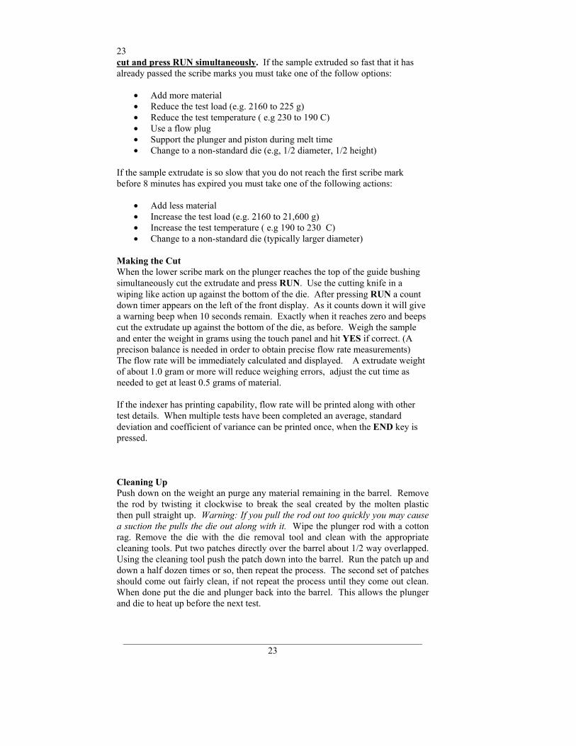
Method "B" Run General Description Method B is an assessment of a material's flow characteristics based on the volumetric displacement rather than weight of extrudate with time as in Method A. Unlike Method A, no cutting and weighing of the extrudate is required to perform a Method B test. Results from Method B test can be expressed directly as Melt Flow Volume (MFV) in ml/10 min. To relate the results of a Method B run back to Method A, the apparent melt density must be known. The determination of the apparent density is illustrated in the next section using Method A/B. Without the apparent melt density MFR can not be calculated using Method B. Some companies use MFV directly without ever determining MFR. The pistons downward travel time is determined from a counter initiated by an LED sensor or optical encoder. The LED senses an opaque flag on a transparent tape hung off the top of the piston rod. With all Kayeness flags, Method A and B start in the same place. Flags may be 1/8, 1/4, 1/2, or 1". Multiple flags are discussed in later sections under Enhanced Tests. Recently, Method B has become the more common because it is simpler to run and more precise for routine analysis. In addition, the encoder system makes it possible to get 15 results from one run. Calculations : Method B Flow rate for method B is computed as follows:
MFV MFR R LT
ρ π ρ= =2 600
where R= radius piston (cm), T is time to traverse the distance L (sec), L=length
of flag (cm), ρ=apparent melt density of polymer (g/cc) You should determine the melt densities for your material using your own melt indexer. Variations in technique and difference in material grades can cause differences from user to user. The following table of melt densities can be used as a general guide if you get values which differ by more than 10% from these chances are you are doing something incorrectly. Fillers, reinforcing agents etc. tend to increase the melt density of the material. Notice that apparent melt density is a function of temperature. In general the solid state density is a very poor estimate of the melt density and should not be used. Temperature (C) LDPE HDPE Polybutene-1 PolyPropylene
120 0.797 -- 0.806 0.880 130 0.791 -- 0.800 0.872 140 0.785 -- 0.794 0.864 150 0.780 0.780 0.787 0.852 160 0.777 0.777 0.780 0.840 170 0.770 0.770 0.774 0.819 180 0.765 0.765 0.767 0.758 190 0.760 0.760 0.760 0.754
26
_______________________________________________________________ 26
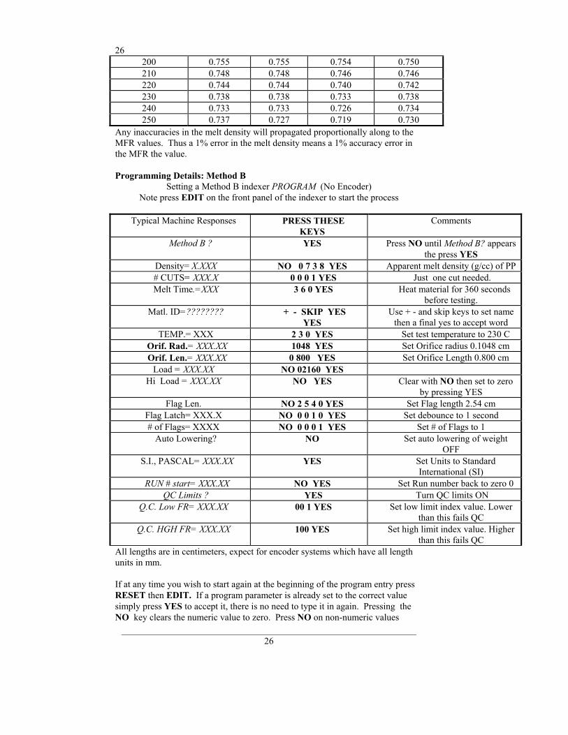
200 0.755 0.755 0.754 0.750 210 0.748 0.748 0.746 0.746 220 0.744 0.744 0.740 0.742 230 0.738 0.738 0.733 0.738 240 0.733 0.733 0.726 0.734 250 0.737 0.727 0.719 0.730
Any inaccuracies in the melt density will propagated proportionally along to the MFR values. Thus a 1% error in the melt density means a 1% accuracy error in the MFR the value. Programming Details: Method B
Setting a Method B indexer PROGRAM (No Encoder) Note press EDIT on the front panel of the indexer to start the process
Typical Machine Responses PRESS THESE
KEYS Comments
Method B ? YES Press NO until Method B? appears the press YES
Density= X.XXX NO 0 7 3 8 YES Apparent melt density (g/cc) of PP # CUTS= XXX.X 0 0 0 1 YES Just one cut needed. Melt Time.=XXX 3 6 0 YES Heat material for 360 seconds
before testing. Matl. ID=???????? + - SKIP YES
YES Use + - and skip keys to set name
then a final yes to accept word TEMP.= XXX 2 3 0 YES Set test temperature to 230 C
Orif. Rad.= XXX.XX 1048 YES Set Orifice radius 0.1048 cm Orif. Len.= XXX.XX 0 800 YES Set Orifice Length 0.800 cm
Load = XXX.XX NO 02160 YES Hi Load = XXX.XX NO YES Clear with NO then set to zero
by pressing YES Flag Len. NO 2 5 4 0 YES Set Flag length 2.54 cm
Flag Latch= XXX.X NO 0 0 1 0 YES Set debounce to 1 second # of Flags= XXXX NO 0 0 0 1 YES Set # of Flags to 1 Auto Lowering? NO Set auto lowering of weight
OFF S.I., PASCAL= XXX.XX YES Set Units to Standard
International (SI) RUN # start= XXX.XX NO YES Set Run number back to zero 0
QC Limits ? YES Turn QC limits ON Q.C. Low FR= XXX.XX 00 1 YES Set low limit index value. Lower
than this fails QC Q.C. HGH FR= XXX.XX 100 YES Set high limit index value. Higher
than this fails QC All lengths are in centimeters, expect for encoder systems which have all length units in mm. If at any time you wish to start again at the beginning of the program entry press RESET then EDIT. If a program parameter is already set to the correct value simply press YES to accept it, there is no need to type it in again. Pressing the NO key clears the numeric value to zero. Press NO on non-numeric values
27
_______________________________________________________________ 27
causes them to toggle through the various items allowed. Once a program is entered the machine will remember it, even if the power is turned off for anextended period.
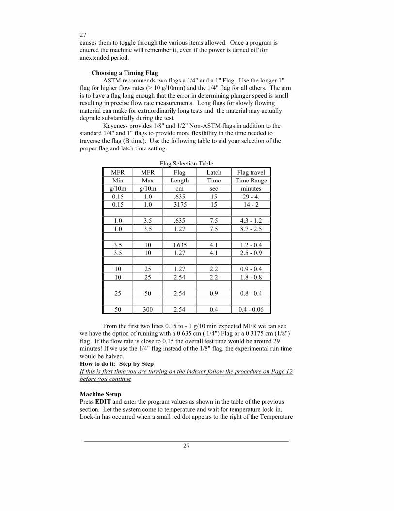
Choosing a Timing Flag ASTM recommends two flags a 1/4" and a 1" Flag. Use the longer 1" flag for higher flow rates (> 10 g/10min) and the 1/4" flag for all others. The aim is to have a flag long enough that the error in determining plunger speed is small resulting in precise flow rate measurements. Long flags for slowly flowing material can make for extraordinarily long tests and the material may actually degrade substantially during the test. Kayeness provides 1/8" and 1/2" Non-ASTM flags in addition to the standard 1/4" and 1" flags to provide more flexibility in the time needed to traverse the flag (B time). Use the following table to aid your selection of the proper flag and latch time setting.
Flag Selection Table MFR MFR Flag Latch Flag travel Min Max Length Time Time Range
g/10m g/10m cm sec minutes 0.15 1.0 .635 15 29 - 4. 0.15 1.0 .3175 15 14 - 2
1.0 3.5 .635 7.5 4.3 - 1.2 1.0 3.5 1.27 7.5 8.7 - 2.5
3.5 10 0.635 4.1 1.2 - 0.4 3.5 10 1.27 4.1 2.5 - 0.9
10 25 1.27 2.2 0.9 - 0.4 10 25 2.54 2.2 1.8 - 0.8
25 50 2.54 0.9 0.8 - 0.4
50 300 2.54 0.4 0.4 - 0.06
From the first two lines 0.15 to - 1 g/10 min expected MFR we can see we have the option of running with a 0.635 cm ( 1/4") Flag or a 0.3175 cm (1/8") flag. If the flow rate is close to 0.15 the overall test time would be around 29 minutes! If we use the 1/4" flag instead of the 1/8" flag. the experimental run time would be halved. How to do it: Step by Step If this is first time you are turning on the indexer follow the procedure on Page 12 before you continue Machine Setup Press EDIT and enter the program values as shown in the table of the previous section. Let the system come to temperature and wait for temperature lock-in. Lock-in has occurred when a small red dot appears to the right of the Temperature
28
_______________________________________________________________ 28
digits (e.g. 230 ) indicating the temperature is stable. Heat up and lock-in must occur with orifice and piston rod in the heat chamber. During heat up the program may be adjusted and the Operator. and Sample ID can be entered by pressing the ID key, using + ,−, and SKIP as described in the KEY PAD section on Page Error! Bookmark not defined..
Loading the Barrel Remove the piston rod and lay on a cotton cloth. Check to see if the die is at the bottom of the barrel. Fill heat chamber with an appropriate charge (see Table on Page 35 or use about 5 grams if nothing is known about the material). Put the sample into the 10 ml beaker. Add about two-thirds of the material into the barrel, using the brown fill tube. The loading should be done in two increments, the first consisting of approximately 60% of the material. Tamp down the material with the packing tool using approximately 20 pounds of force. The packing tool can be driven through the fill tube. If bridging (clogging) of the material occurs in the fill tube, slide the fill tube off to one side (without lifting) and use the fill tool to pack the material in the barrel directly. Move the fill tube back into place. The remaining material should drop down into the barrel. Repeat with the remainder of the material. Bubbles are in your sample charge if a snapping/popping sound is heard at the extrudate is forced through the dir/orifice. If bubbles appear in the extrudate use less material between tamping down. If bubbles continue the sample may not be sufficiently dry. Place the plunger into the barrel and position the plunger arm directly over the slot on the indexer cover. Seat the guide bushing down into the barrel if it as not already fallen into place. The guide bushing should be moving freely on the plunger. Place the weight on the plunger rod.
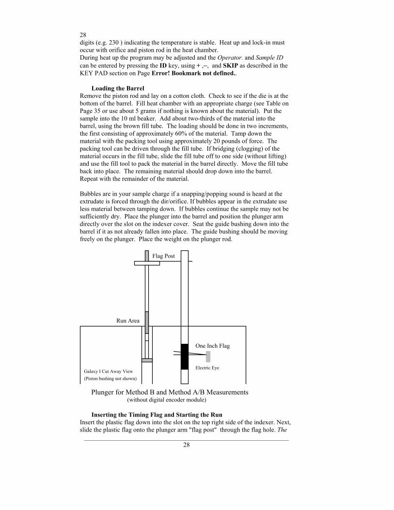
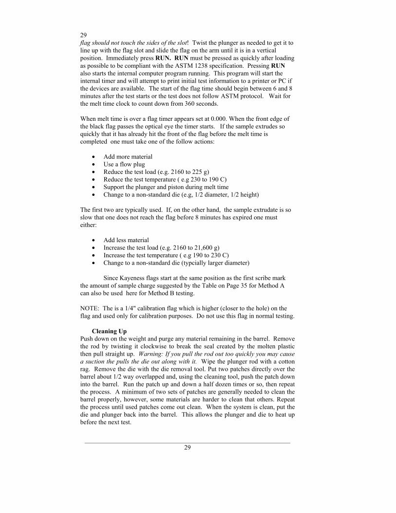
Inserting the Timing Flag and Starting the Run
Insert the plastic flag down into the slot on the top right side of the indexer. Next, slide the plastic flag onto the plunger arm "flag post" through the flag hole. The
Plunger for Method B and Method A/B Measurements(without digital encoder module)
Run Area
Flag Post
One Inch Flag
Electric EyeGalaxy I Cut Away View(Piston bushing not shown)
29
_______________________________________________________________ 29
flag should not touch the sides of the slot! Twist the plunger as needed to get it to line up with the flag slot and slide the flag on the arm until it is in a vertical position. Immediately press RUN. RUN must be pressed as quickly after loading as possible to be compliant with the ASTM 1238 specification. Pressing RUN also starts the internal computer program running. This program will start the internal timer and will attempt to print initial test information to a printer or PC if the devices are available. The start of the flag time should begin between 6 and 8 minutes after the test starts or the test does not follow ASTM protocol. Wait for the melt time clock to count down from 360 seconds. When melt time is over a flag timer appears set at 0.000. When the front edge of the black flag passes the optical eye the timer starts. If the sample extrudes so quickly that it has already hit the front of the flag before the melt time is completed one must take one of the follow actions:
• Add more material • Use a flow plug • Reduce the test load (e.g. 2160 to 225 g) • Reduce the test temperature ( e.g 230 to 190 C) • Support the plunger and piston during melt time • Change to a non-standard die (e.g, 1/2 diameter, 1/2 height)
The first two are typically used. If, on the other hand, the sample extrudate is so slow that one does not reach the flag before 8 minutes has expired one must either:
• Add less material • Increase the test load (e.g. 2160 to 21,600 g) • Increase the test temperature ( e.g 190 to 230 C) • Change to a non-standard die (typcially larger diameter)
Since Kayeness flags start at the same position as the first scribe mark the amount of sample charge suggested by the Table on Page 35 for Method A can also be used here for Method B testing. NOTE: The is a 1/4" calibration flag which is higher (closer to the hole) on the flag and used only for calibration purposes. Do not use this flag in normal testing.
Cleaning Up
Push down on the weight and purge any material remaining in the barrel. Remove the rod by twisting it clockwise to break the seal created by the molten plastic then pull straight up. Warning: If you pull the rod out too quickly you may cause a suction the pulls the die out along with it. Wipe the plunger rod with a cotton rag. Remove the die with the die removal tool. Put two patches directly over the barrel about 1/2 way overlapped and, using the cleaning tool, push the patch down into the barrel. Run the patch up and down a half dozen times or so, then repeat the process. A minimum of two sets of patches are generally needed to clean the barrel properly, however, some materials are harder to clean that others. Repeat the process until used patches come out clean. When the system is clean, put the die and plunger back into the barrel. This allows the plunger and die to heat up before the next test.
30
_______________________________________________________________ 30
With materials that are thermally stable (less than 5% viscosity change over 1/2 hour) we recommend only cleaning the barrel between runs of the exact same material. For materials that degrades or are moisture sensitive it is recommend that both the barrel and the die be cleaned completely. To clean the die use the die removal rod and push the die up from the bottom of the barrel and out the top. Wipe it with the cotton rag and clean it by running the drill bit through it several times. Remove material that collects in the grooves of the drill bit and repeat until the drill passes easily through the die. Scrape the die with the cutting knife if needed to clean the top and bottom faces. For materials that crystallize quickly you can clean the die by first running a drill bit up into the die while it is hot and in the indexer. This will make it much easier to get the cleaning drill bit in when the die is removed and the material starts to solidify. USER TIP: Experienced users often listen for the double bounce of the die when they drop it back into the barrel to know that the barrel is clean. Also, while the die is out look down the barrel bore to be sure it is clean (use safety glasses when looking down the barrel!). The inside surface of the barrel is smooth and shiny when completely clean. If you don't use gloves you will eventually get burned. If you are using a PVC die (D3364 unstable materials) be sure to get the material out of the conical top section. Standard dies have a flat entrance and exit. When the die is out of the barrel it cools down quickly. The longer it is out the longer the wait for the temperature to stabilize. Minimizing the time the die stays out of the machine will increase the number of tests you can run. When the temperature on the front display is within 0.2 C of the setpoint you can begin the next test. Loading material will cause a small temperature change even if temperature setpoint was locked in. The melt time (360 seconds) will allow ample time to get the temperature to setpoint before the first data point is collected. Always leave the machine clean. If it is going to sit at room temperature for an extended period of time you may wish to coat the barrel with a light machine oil to prevent rusting. The oil will need to be purged from the machine before accurate data can be obtained.
31
_______________________________________________________________ 31
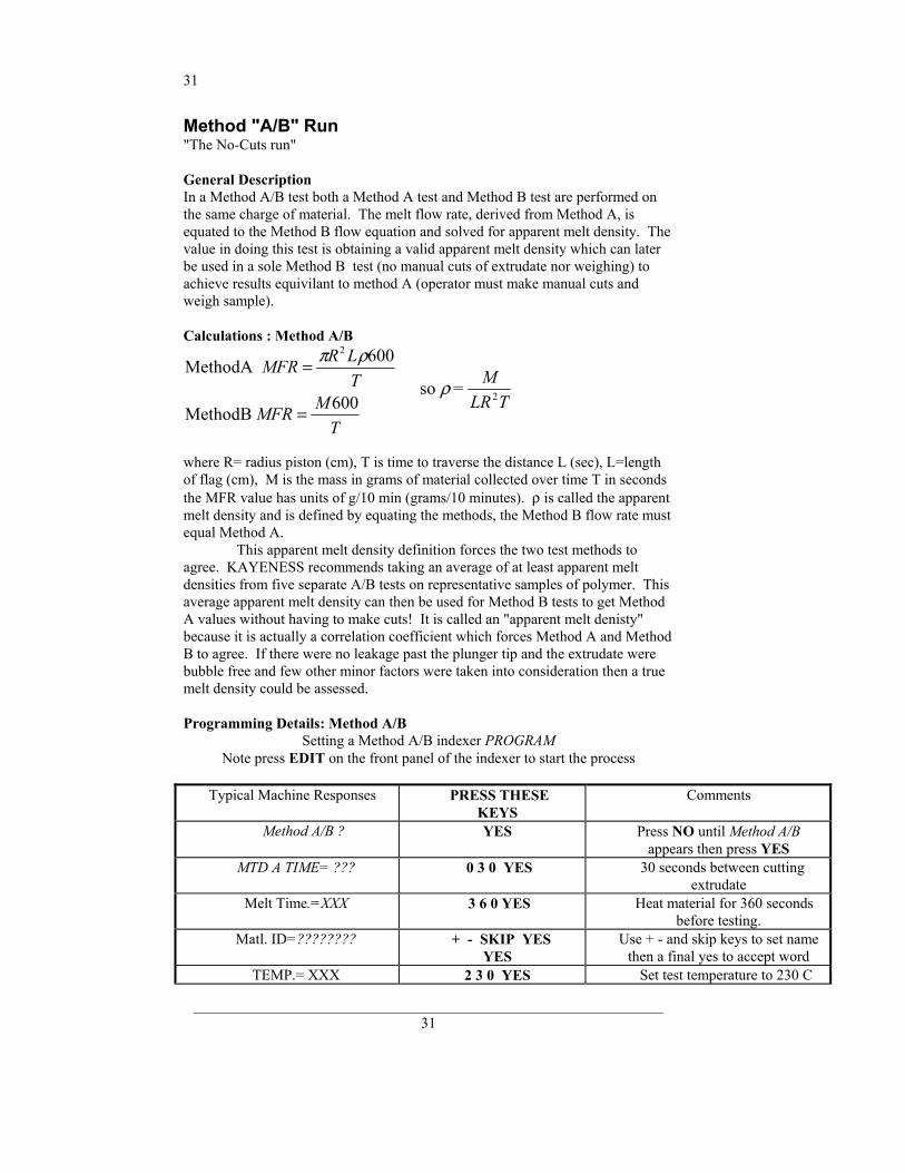
Method "A/B" Run "The No-Cuts run" General Description In a Method A/B test both a Method A test and Method B test are performed on the same charge of material. The melt flow rate, derived from Method A, is equated to the Method B flow equation and solved for apparent melt density. The value in doing this test is obtaining a valid apparent melt density which can later be used in a sole Method B test (no manual cuts of extrudate nor weighing) to achieve results equivilant to method A (operator must make manual cuts and weigh sample). Calculations : Method A/B
MethodA
MethodB
MFR R LT
MFR MT
=
=
π ρ2 600
600 so =ρ M
LR T2
where R= radius piston (cm), T is time to traverse the distance L (sec), L=length of flag (cm), M is the mass in grams of material collected over time T in seconds the MFR value has units of g/10 min (grams/10 minutes). ρ is called the apparent melt density and is defined by equating the methods, the Method B flow rate must equal Method A. This apparent melt density definition forces the two test methods to agree. KAYENESS recommends taking an average of at least apparent melt densities from five separate A/B tests on representative samples of polymer. This average apparent melt density can then be used for Method B tests to get Method A values without having to make cuts! It is called an "apparent melt denisty" because it is actually a correlation coefficient which forces Method A and Method B to agree. If there were no leakage past the plunger tip and the extrudate were bubble free and few other minor factors were taken into consideration then a true melt density could be assessed.
Programming Details: Method A/B
Setting a Method A/B indexer PROGRAM Note press EDIT on the front panel of the indexer to start the process
Typical Machine Responses PRESS THESE
KEYS Comments
Method A/B ? YES Press NO until Method A/B appears then press YES
MTD A TIME= ??? 0 3 0 YES 30 seconds between cutting extrudate
Melt Time.=XXX 3 6 0 YES Heat material for 360 seconds before testing.
Matl. ID=???????? + - SKIP YES YES
Use + - and skip keys to set name then a final yes to accept word
TEMP.= XXX 2 3 0 YES Set test temperature to 230 C
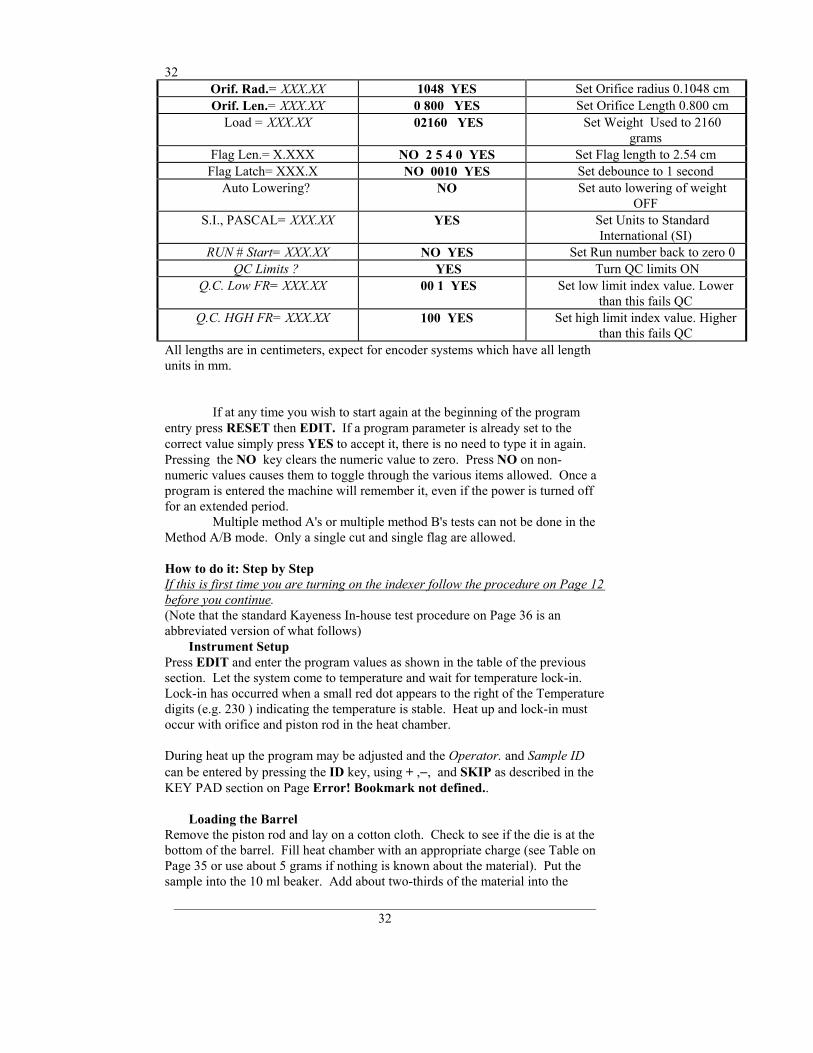
32
_______________________________________________________________ 32
Orif. Rad.= XXX.XX 1048 YES Set Orifice radius 0.1048 cm Orif. Len.= XXX.XX 0 800 YES Set Orifice Length 0.800 cm
Load = XXX.XX 02160 YES Set Weight Used to 2160 grams
Flag Len.= X.XXX NO 2 5 4 0 YES Set Flag length to 2.54 cm Flag Latch= XXX.X NO 0010 YES Set debounce to 1 second
Auto Lowering? NO Set auto lowering of weight OFF
S.I., PASCAL= XXX.XX YES Set Units to Standard International (SI)
RUN # Start= XXX.XX NO YES Set Run number back to zero 0 QC Limits ? YES Turn QC limits ON
Q.C. Low FR= XXX.XX 00 1 YES Set low limit index value. Lower than this fails QC
Q.C. HGH FR= XXX.XX 100 YES Set high limit index value. Higher than this fails QC
All lengths are in centimeters, expect for encoder systems which have all length units in mm.
If at any time you wish to start again at the beginning of the program entry press RESET then EDIT. If a program parameter is already set to the correct value simply press YES to accept it, there is no need to type it in again. Pressing the NO key clears the numeric value to zero. Press NO on non-numeric values causes them to toggle through the various items allowed. Once a program is entered the machine will remember it, even if the power is turned off for an extended period. Multiple method A's or multiple method B's tests can not be done in the Method A/B mode. Only a single cut and single flag are allowed. How to do it: Step by Step If this is first time you are turning on the indexer follow the procedure on Page 12 before you continue. (Note that the standard Kayeness In-house test procedure on Page 36 is an abbreviated version of what follows)
Instrument Setup Press EDIT and enter the program values as shown in the table of the previous section. Let the system come to temperature and wait for temperature lock-in. Lock-in has occurred when a small red dot appears to the right of the Temperature digits (e.g. 230 ) indicating the temperature is stable. Heat up and lock-in must occur with orifice and piston rod in the heat chamber. During heat up the program may be adjusted and the Operator. and Sample ID can be entered by pressing the ID key, using + ,−, and SKIP as described in the KEY PAD section on Page Error! Bookmark not defined..
Loading the Barrel Remove the piston rod and lay on a cotton cloth. Check to see if the die is at the bottom of the barrel. Fill heat chamber with an appropriate charge (see Table on Page 35 or use about 5 grams if nothing is known about the material). Put the sample into the 10 ml beaker. Add about two-thirds of the material into the
33
_______________________________________________________________ 33
barrel, using the brown fill tube. The loading should be done in two increments, the first consisting of approximately 60% of the material. Tamp down the material with the packing tool using approximately 20 pounds of force. The packing tool can be driven through the fill tube. If bridging (or clogging)of the material occurs in the fill tube, slide the fill tube off to one side (without lifting). Pack the material in the barrel directly with the packing rod. Move the fill tube back into place. The remaining material should drop down into the barrel. Repeat with the remainder of the material. Bubbles are in your sample charge if a snapping/popping sound is heard at the extrudate is forced through the dir/orifice. If bubbles appear in the extrudate use less material between tamping down. If bubbles continue the sample may not be sufficiently dry. Place the plunger into the barrel and position the plunger arm directly over the slot on the indexer cover. Seat the guide bushing down into the barrel if it as not already fallen into place. The guide bushing should be moving freely on the plunger. Place the weight on the plunger rod.
Plunger for Method B and Method A/B Measurements(without digital encoder module)
Run Area
Flag Post
One Inch Flag
Electric EyeGalaxy I Cut Away View(Piston bushing not shown)
Inserting the Timing Flag
Insert the plastic flag down into the slot on the top right side of the indexer then slide the flag onto the plunger arm through the flag hole. Make sure that the flag does not touch the sides of the flag slot. Twist the plunger as needed to get it to line up with the flag slot and slide the flag on the arm until it is in a vertical position. Immediately press RUN. RUN must be pressed as quickly after loading as possible to be compliant with the ASTM 1238 specification. Pressing RUN also starts the internal computer program running. This program will start and internal timer and will attempt to print initial test information to a printer or PC if the devices are available. The start of the flag time should begin between 6 and 8
34
_______________________________________________________________ 34
minutes after the test starts or the test does not follow ASTM protocol. Wait for the melt time clock to count down from 360 seconds. When melt time is over a flag timer appears set at 0.000. When the front edge of the black flag passes the optical eye the timer starts. If the sample extruded so quickly that it has already hit the front of the flag prior to the melt time passing one must either:
• Add more material • Use a flow plug • Reduce the test load (e.g. 2160 to 225 g) • Reduce the test temperature ( e.g 230 to 190 C) • Support the plunger and piston during melt time • Change to a non-standard die (e.g, 1/2 diameter, 1/2 height)
The first two are typically used. If, on the other hand, if the sample extrudate is so slow that you do not reach the flag before 8 minutes has expired you must take one of the following actions:
• Add less material • Increase the test load (e.g. 2160 to 21,600 g) • Increase the test temperature ( e.g 190 to 230 C) • Change to a non-standard die (typcially larger diameter)
Since Kayeness flags start at the same position as the first scribe mark the amount of sample charge suggested by the Table on Page 35 works for both Method A and Method B testing. NOTE: This is a 1/4" calibration flag which is higher (closer to the hole) on the flag and used only for calibration purposes. Do not use this flag in normal testing.
Making the Cut
When the lower scribe mark on the plunger reaches the top of the guide bushing simultaneously cut the extrudate and press RUN. Use the cutting knife in a wiping like action up against the bottom of the die. After pressing RUN a count down timer appears on the left of the front display. As it counts down it will give a warning beep when 10 seconds remain. Exactly when it reaches zero and beeps cut the extrudate up against the bottom of the die, as before. Weigh the sample and enter the weight in grams using the touch panel then press YES. You may have to wait for the flag to traverse the photo eye for slow flowing materials. A precison balance is needed in order to obtain correct flow rate measurements. The flow rate and melt density will be immediately calculated and displayed. A extrudate weight of about 1.0 gram or more will reduce weighing errors, adjust the cut time as needed to get at least 0.5 grams of material. If the indexer has printing capability, flow rate will be printed along with other test details. When multiple tests have been completed an average, standard deviation and coefficient of variance can be printed once, when the END key is pressed.
Cleaning Up
Clean up is the same as that for Method B.
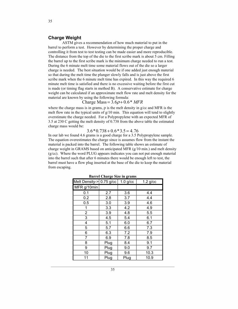
35
_______________________________________________________________ 35
Charge Weight ASTM gives a recommendation of how much material to put in the barrel to perform a test. However by determining the proper charge and controlling it from test to test testing can be made easier and more reproducible. The distance from the top of the die to the first scribe mark is about 5 cm. Filling the barrel up to the first scribe mark is the minimum charge needed to run a test. During the 6 minute melt time some material flows out of the die so a larger charge is needed. The best situation would be if one added just enough material so that during the melt time the plunger slowly falls and is just above the first scribe mark when the 6 minute melt time has expired. In this way the required 6 minute melt time is satisfied and there is no excessive waiting before the first cut is made (or timing flag starts in method B). A conservative estimate for charge weight can be calculated if an approximate melt flow rate and melt density for the material are known by using the following formula:
Charge Mass = +3 6 0 6. . *ρ MFR where the charge mass is in grams, ρ is the melt density in g/cc and MFR is the melt flow rate in the typical units of g/10 min. This equation will tend to slightly overstimate the charge needed. For a Polypropylene with an expected MFR of 3.5 at 230 C getting the melt density of 0.738 from the above table the estimated charge mass would be:
3 6 0 738 0 6 3 5 4 76. * . . * . .+ = In our lab we found 4.6 grams is a good charge for a 3.5 Polypropylene sample. The equation overestimates the charge since is assumes flow from the instant the material is packed into the barrel. The following table shows an estimate of charge weight in GRAMS based on anticipated MFR (g/10 min.) and melt density (g/cc). Where the word PLUG appears indicates you can not put enough material into the barrel such that after 6 minutes there would be enough left to test, the barrel must have a flow plug inserted at the base of the die to keep the material from escaping.
Barrel Charge Size in grams Melt Density-> 0.75 g/cc 1.0 g/cc 1.2 g/cc MFR g/10min
0.1 2.7 3.6 4.4 0.2 2.8 3.7 4.4 0.5 3.0 3.9 4.6 1 3.3 4.2 4.9 2 3.9 4.8 5.5 3 4.5 5.4 6.1 4 5.1 6.0 6.7 5 5.7 6.6 7.3 6 6.3 7.2 7.9 7 6.9 7.8 8.5 8 Plug 8.4 9.1 9 Plug 9.0 9.7 10 Plug 9.6 10.3 11 Plug Plug 10.9
36
_______________________________________________________________ 36
12 Plug Plug 11.5 13 Plug Plug Plug
Kayeness In-house Standard Operating Procedure
Indexer Testing of GRAY PolyPropylene Control Resin (MFR about 3.6 g/10 minutes, HIMONT PP, use only LOT# 13891)
Introduction: This standard operating procedure is to be used to qualify Kayeness employees in the use of melt indexers. It sets forth the proper operation of the equipment and specific test procedures and methodology to be used by the operator. In an effort to make the results as consistent as possible we have found it necessary to go beyond the standard ASTM D1238 method. Control limits ± 3σ of 3.0% have been obtained using this method. NOTE the A/B method should always be used for operator training. Only the A/B method assess cutting and flag methodology together.
The Test Procedure for Indexer SQC runs: Instrument Preparation
Use 2060 weight. Use the standard die. (D=0.0825", L=0.315") Use the 1/4" flag Set MTD A Time to 180 sec All calibrations completed. All machine oils removed from barrel and machine is LEVEL. Die Dimension Check. (Go, No-Go) Die Length Check. (Micrometer, = 8.0 mm or 0.315") Die Clean Check, Clean if Dirty. Machine should be on for 20 minutes set to 230C, Temp locked. Barrel Clean Check, Clean if Dirty while HOT. Plunger Clean Check, Guide bushing must move freely. Plunger Tip Clean Check, Clean if Dirty. Tools Ready (Packer, Die remover, brass brush cleaner) Flag Nearby. Fill Funnel Nearby Connect mini-printer or standard printer to indexer. Machine program set as shown on attached sheet. (1/4" Flag, Density 0.735 ) Set Operator ID to operator initials and Material ID to GRAY At least one purge of gray material performed. (To purge: about 5 grams, wait 2 minutes hand purge) Clean MI barrel after purge (2 patches, double pass, two times) Reinstall plunger and let machine re-lock the temperature.
37
_______________________________________________________________ 37
Conducting the Test Weigh out 4.6 grams ± 0.1 gram of Gray, Polypropylene, Lot# 13891 material.
DO THESE AS QUICKLY AS POSSIBLE Pour 2/3 material through funnel into barrel, pack until little movement occurs when pushing on packer. Pour in remainder of material, Pack as before. Wipe plunger before placing into barrel. Seat plunger guide bushing. Place flag on arm & in flag hole. Place weight on plunger. Press RUN button. Make cut and Press RUN button when first scribe reached. Make second cut when MTD A time expired (beep)
The test should run to completion by itself , enter the mass of extrdate collected over the cut time then press END then YES to print to the mini printer or Okidata 320. Push down on weight hard to purge remaining material out.
Clean Up Always use two patches (must have enough frictional forces against barrel to clean). Eight or more strokes completely up and down the barrel. Toss patches & repeat. Or use the power cleaning tool and make two cleaning passes with fresh patches each time. If the last run of control: Push the die up and out using the orifice removal tool. Hold the die in a glove and run a drill bit through the die. Run MI die brush through the orifice. Clean top and bottom surfaces. Re-clean the barrel to get area blocked by orifice. Leave die out so it can be inspected before next runs. Leave die on cleaning drill bit. TURN MACHINE OFF ONLY IF IT IS CLEAN.
Out of Control Action List Was Clean? Check density value Check tip diameter (> 0.3727) Check Die (clean, diameter length OK?) Check Machine is Level Check Temp Check weights used +/- 0.5% Check balance used to weight extrudate
38
_______________________________________________________________ 38
Piston Rod Bent? Check insulator can hitting bottom of barrel? Heater gap alignment (older units)
Generic Run Check List
Immediately prior to pressing RUN Plunger in machine? Guide Bushing in place? Area between crosshead and swing arm clear? PC (MIWORKS) or printer ready?
Prior to loading Sample Is material properly prepared (dried, mixed, check for contaminates) Machine on 20 minutes? Correct Die in machine? Correct program being run? Hand tools in position (packing funnel and tool, cleaning drill bit etc.) Encoder Arm in place?
Long term items (in order of importance) Are die diameters within spec. (passed G0-No Go gage, ASTM, ISO, DIN?) Temperature calibration OK? Piston Tip Diameter within spec.? Barrel Diameter OK?
Enhanced Tests Using theDigital Encoder The digital encoder is an option for model 7050. 7053 and 7054 melt indexers. This option makes conductiong melt index experiments much easier because the user no longer has to use the clear plastic hang down flags to track piston movement. Instead, a small arm sits underneath the head of the piston assembly. When the piston moves, so does the arm. A system of gears in the encoder To Test Encoder System: From the main menu screen "READY>" Press <TEST> Display will show: "ENCODER TEST?" Press <YES> At this point the display will show both position and MFI. For example, when the arm is in the home position (lowered and locked) the display will read: "P=105.00 MF=.0000".The user can move the encoder arm up/down at this point

39
_______________________________________________________________ 39
to verity that piston movement is being read. The melt flow display calcultes a real-time flow and updates the display frequently. To Calibrate/ReHome Encoder Position: Automatic Calibration: Place the arm in the home (lowered and locked) position. The arm position is automatically zeroed when the insturment is powered on.. Manual Calibration: Place the arm in the home (lowered and locked) position. From the main screen "READY>" press <SHIFT> <0>. The display flashes "POSITION=105.00". To periodically verify the calibration, place the arm in the home position. then place the unit in <TEST> mode and verity that P=105.00 +/- 1mm Running Encoder Tests: There are 3 modes of programming the encoder system. All are accessed by pressing <SHIFT><PRINT>. 1) Manual Mode: All positions for flag starts are programmed by the user. NOTE: Software does not check for flag boundry/crossover problems. 2) Auto Mode: Positions are automatically calculated using a start and end position from the user. NOT 3) AutoFlag Mode: The system automatically calculated which flag to use based on real-time flow. Th lengths (1/4" & 1", 1/8" single flag tests). NOTE: Melt time must expire before passing P=00.00 in order for proper flag to be calculated Note: These modes only apply to method B tests.To perform an A/B test, AutoFlag must be off. Mode Selection: From the main menu screen "READY>' prompt press <SHIFT><PRINT> (options menu). Display shows "Auto Flag: OFF?" If the AutoFlag is desired change to ON via <NO><YES> sequence. NOTE: if AutoFlag=ON the manual mode prompt is not displayed. The display shows: "Manual Mode=OFF?" If Auto Mode is desired, enter <YES>. To select Manual Mode enter <NO> then <YES>.
MANUAL Mode Programming After selecting the Manual Mode by turning "Manual Mode: ON" (see mode selection) go into Edit mode.From the main menu "READY>": Press <EDIT>. Go through questions until "POS#1=xx.xx" appears. Enter a value greater than 0.00mm (0.50 is recommended, i.e. POS#1=00.50). Enter the next position. NOTE: The start of each position must be greater than the previous position + flag length + spacing (minimum recommended spacing is 0.50 mm). Example: POS#1=0.50 mm Flag Length = 6.35 mm. Enter POS#2=9.00 mm) Enter up to 15 positions keeping in mind that ASTM/ISO require that the intire test occur over a maximum distance of 25.4 mm/30mm respectively. The total
40
_______________________________________________________________ 40
number of positions equals the total # of flags. Enter a position = 0 to finnish position selection. Example: If the # flags disired is 5, Enter POS #6=00.00.
AUTOMATIC Mode Programming First, select the Automatic Mode by turning "Manual Mode: OFF", from the options menu. From the main menu "READY>" Press <EDIT>.
The number of flags is the number of timed measurements that will be conducted. POS#1 is typically 00.50. That means that the measurements begins 0.5 mm after the plunger enter the measurement area (the area between the scribe marks). ENDPOS is 25.4. That is end position of the arm. The test comfortably ends here without running out of material. The user will bne promped for run parameters as with standard tests. When prompted to enter "Flag Len.=XX.XX" Enter the desired flag length, for example Flag Len.=01.50 <ENTER>. The user will then see the prompt: "# of Flags = XXXX" Enter the desired number of flags, for example "# of Flags = 0010<ENTER>.The display will then prompt the user position number 1: "POS#1=XX.XX" Enter 00.50 <ENTER> for the starting position. The display will then prompt the user to enter the overall test length: "END POS = XX.XX" Enter 25.4 <ENTER> for the overall length. The display will show "INC POS=02.49" This is the incremental start position for each new flag. Press <YES>. Note: The maximum value is 30 mm as per ISO limits. ASTM suggests a value of 25.4mm. Note: If the flag length is too long to fit then a new flag length will be calculated. A double beep is heard after entering END POS when this happens. FLAG LENGTH < (ENDPOS-POS#1) / # of Flags
Digital Encoder Run Tests
To run a Method B or Method A/B test with the digital encoder, the following steps are followed: Program the instrument test setup as described in the previous sections. Fill the barrel with the test sample, pack and place weight on the rod Raise the encoder arm up from the locked position Press <RUN> During pre-melt time the following is displayed: P=-XX.XX MT=XXX.X
The following values must be input using the following formula: FLAG LENGTH < (ENDPOS-POS#1) / # of Flags
41
_______________________________________________________________ 41
After the preMelt time is over the display will show position ("P") and the real time flow rate ("MF"). After the zero position of the encoder is passed, the display will read: P=00.05 MF=3.654 (depending on the samples MI) As each subsequent flag is processed, the display replaces "P" with the run number for that particular flag, for example: 1=01.55 MF=3.765 where 1 is the first flag, 2 is the second flag, and so on.
General Operating Notes: 1) Always place the arm into the lowered and locked position before cleaning and at the end of the day. This prevents damage and ensures that the encoder arm will be in the proper position upon powerup. 2). If position gets 'lost' during calibration procedure at the start of the test., go back and preform a manual "re-home" via <SHIFT><0>. 3) Never place any severe force against the side of the arm. 4) All dimensions are in mm. Orifice diameter is asked instead of orifice radius. 5) The real time flow during the test is an approximate value and should not be used as an absolute value. Fractional flows belos 1.0 MFI will appear to change by larger steps due to resolution of sample time. 6) The encoder absolute resolution is .015 mm overall accuracy +/- 0.0254 mm. 7) Results on multiple flag runs are printed at tthe end of the test. This differs from our standard Galaxy I melt indexer.
Multiple Method B using the Digital Encoder Why do it? • No manual cuts • Check how homogeneous a sample is within a charge. • Get better precision (averages are less variable than a single observations) • See if barrel pressure drop is significant • Gain ability to reject data point if bubble or air pocket The GALAXY can handle five flags in one run and compute the shear stress, shear rate and viscosity for each flag. A tape with up to five flags may be used even if two (or three, etc.) is selected. The system will count the first two and ignore the remaining flags.
Flow Rate Ratio test and the Pneumatic Lift Option What is it? Flow rate ratio is a tests used to obtain two flow rates at two different shear rates, of generally a 10:1 ratio. For example, the first might be a 2,160 gram weight with the second being a high load flow rate by the first you have flow rate ratio or one number relating the slope of the curve. For example, tapes are available with a ¼" flag and a 1" flag above it. Once the ¼" flag passes the eye, the low weight is removed and the high load is applied or a high load is added. Immediately after the second flag passes, the two flow rates and the flow rate ratio are computed and printed.
42
_______________________________________________________________ 42
It is strongly suggested that this test be conducted if you have purchased the Pneumatic lift option from KAYENESS, Inc. The weights involved are quite heavy and dangerous for an operatore to be routinely lifting. The pheumatic lift automatically and safely lifts the weights as needed. Why do it? Assess shear thinning ability of materialCorrelation to MWD Flow Rate Ratio - How to Do It (if you have the option installed) (Note: Flow ratio can only be run in one pass in Method B). a. In the edit mode change the High Load 00000 to your high load weight in grams. This triggers the computer to perform a new test. Also enter the High Load Flag Length (cm) and the High Load Latch Time. The latch time can be zero or any low number of seconds. It can never be more than the time of the second flag. b. After filling, the melting procedure is the same as before, and press RUN. When the first flag passes the electronic eye, remove the light weight and lower-or just add the heavy weight. c. After both flags are through, the flow rate of each will be computed along with flow rate ratio. Upon completion of the test, All data will be printed out.
Independent tests:One test run with light weight and one with a heavyweight.
Singular test with manual lift off: In this option a flag is used with two separate
black regions. The light weight is placed on the piston and
when the 1st flag exits the light weight is removed and heavy
weight is lower manual by pressing DN.
Singular test with auto lower: The heavy weight is lowered directly on top
of the small weight. The heavy adder weight has a special
indent for alignment and an impact pad at it's base. The sum of
the two weights must correspond to the weight desired.
Auto Raise Feature 1) In EDIT mode, after auto lower prompt "AUTO LOWERING?" Press <YES> The raise timer prompt will appear "RAISE TIME = 000.0 Set this to the desired value. Press <YES> example: If MI = 50 g/10 minutes set the raise timer to 30 seconds 2) After the test is performed, the flow rate is displayed in the LED. For example
"Fl= 49.92" The raise timer will activate at this point. After the raise time has expired, an
alarm will sound indicating that the pneumatic lift will be raising the weight. The alarm sequence is :
43
_______________________________________________________________ 43
2 short beeps pause 2 short beeps pause 2 short beeps pause 2 short beeps At this point the display will read "Raising Weight" Note: If the user wants to
ABORT (perhaps the material has not complelely exited the barrel)pressing <RESET> will prevent the autoraise feature from lifting the weight.
Calculating I.V. from the Melt Indexer Background and General Description Intrinsic Viscosity (IV, ASTM D3835) is a "wet chemistry" technique used to assess the specific volume of isolated polymer chain when dissolved in a good solvent. It has been used to determine molecular weight relying on the key assumptions of isolated flexible linear chains. Melt viscosity measurement is another empirical (non-absolute like I.V.) way to assess molecular weight. Melt Viscosity and Intrinsic Viscosity have been determined to be related in such a way that IV can be directly calculated from Melt Index values. This is described in greater detail in the applications brief, "Correlating Melt Rheology of PET to Solution Intrinsic Viscosity" by J. Reilly and P. Limbach., available from KAYENESS on request. Sample Restrictions: Intrinsic Viscosity calculations are valid only if the flexibility of the polymeric backbone does not change. The molecular weight of the polymer to be examined can change but the backbone composition and the sequence distribution can not change. How to do it This feature allows the Melt Indexer to correlate Melt Flow Rate (g/10 min) to Intrinsic Viscosity (dl/g). It is automatically activated when the temperature is set to 285 Celsius. IV results are based on an empirical study (see Figure 1) which included various PET resins. A reference material of known IV is needed to calibrate the melt indexer. After determining the average Melt Flow Rate of at least 3 runs Perform the following: Press key TEST answer NO to Flag and Temp tests _ Display Reads: "IV Reference?Y/N Press YES Display reads: "REF MI= xx.xx" (e.g. "REF MI= 54.00" ) Enter reference material Melt Flow_ Press YES
44
_______________________________________________________________ 44
Display reads: "MI=xx.xx IV=x.xxx" e.g. "MI=54.00 IV=0.673" Enter reference material IV value Press YES Note: MI value is only displayed here _ Display Reads: "IV OFFSET = 0.000" Press YES Note: This is the offset from the original correlation curve. NOTES: A material of known I.V. are needed to correctly perform a new reference IV. If original reference is desired re-enter the values shown in above example. It is critical that the PET material to be evaluated is properly prepared and tested to obtain meaningful IV and melt flow values. The following procedures and_techniques are referenced in the paper titled "Correlating_Melt Rheology of PET to Solution Intrinsic Viscosity" by_J.F. Reilly and A.P. Limbach. _ Minimum: 4 hours @ 160 C Maximum: 12 hours with above condition Note: See paper called "Getting optimum results from PET resin drying" Temperature = 285 C Use 1 inch flag_ Melt time = 360 sec 2160 kg weight Cut Time = 30 sec Acceptable Methods A A/B B Note: Always perform a purge run of a new sample After each run: Clean Barrel Clean Die (remove first)
Maintenance Daily Keep your indexer barrel and die clean. Piston should spin easily when placed into a clean barrel. Use of solvents??
Weekly Give good cleaning with brass brush. Oven cleaner.
Long Term Electronics Clean the electronics module out with clean air every six months to one year, more often in dirty environments. This will keep electrical contacts and connections from being shorted out by dust, dirt, carbon particulate, or other contamination. Temperature Calibration
45
_______________________________________________________________ 45
NOTE: this proceedure requires that the stainless steel cover be removed. Electronic adjustment pots on the temperature control board must be adjusted to set the 0 ºC point. Exercise caution when working around sensitive components. Please call KAYENESS with questions if you are unsure about any calibration porceedure. To calibrate temperature, a reference must be obtained. In general, a calibrated expanded scale thermometer is used. Preferably it should be certified by the National Institute of Standards and Technology (NIST), formerly the National Bureau of Standards. Remember: the NIST certifies the thermometer at that moment. With repeated heating and cooling, the volume of the bulb changes, generally forcing the thermometer higher. One Temperature Reference
To perform a single temperature calibration go into EDIT mode and set the temperature of the machine to the temperature of the calibration thermometer. Allow the machine to come within a few degrees of the thermometers nominal value then carefully insert the thermometer into the thermometer well. DO NOT REMOVE THE RTD SENSOR . The thermometer well is just in front of the RTD probe. Allow the system to equilibrate for a minimum of 30 minutes after placing the thermometer into the machine. Read the thermometer and check the thermometer's calibration certificate to determine if any adjustments are needed to determine the true temperature. For example, the thermometer shows the mercury column to be at 230.4 C the calibration certificate says this thermometer reads 0.1 C high so the true temperature is 230.3 and this is what we want the front panel display of the indexer to display. Remove the front top cover of the indexer and locate the slot in the clear plastic sheet on the LEFT side of the machine. There are four adjustment screws from the top down they are labeled OFFSET, GAIN, COMP and EYE. Do not adjust the COMP setting! To perform the calibration one must first disconnect the temperature control systems so it does not change the temperature of the machine as we are trying to calibrate it! To "lock" the temperature in place simply press down both the RED and BLACK buttons together on each side of the rheometers front LED display. Hold the buttons down for 2 seconds. At this point, you should see the current temperature reading change to some new number. After letting go of the buttons you should see a dot flashing on the left side of the LED display (a dot on the right side may also be flashing). If you do not see any flashing dot press down both the RED and BLACK buttons and release only after you see the number on the front panel change. Only when the flashing dot appears should you turn the OFFSET screw on the left side of the indexer until the FRONT display matches the true temperature as determined from your thermometer and its calibration certificate. Once set correctly press either the BLACK or RED button down to start the system controlling again. The flashing dot should disappear once the RED or BLACK button is pressed. After about 15 minutes the indexer should come back to controlling temperature and the rheometer and thermometer readings should agree.
46
_______________________________________________________________ 46
Carefully remove the hot thermometer and place it on some cotton patches to cool. Store it in a protective box along with its calibration certificate. Please call Kayeness Tech Support if you have any questions. Two Temperature References Remove the front top cover of the indexer and locate the slot in the clear plastic sheet on the LEFT side of the machine. There are four adjustment screws, from the top down they are labeled OFFSET, GAIN, COMP and EYE. The two point temperature calibration can be performed using an ice bath or two certified (NIST traceable) thermometers which cover the range of testing being performed. Using an ICE BATH If using an ice bath go into the EDIT mode and set the TEMP. to 0.0. NOTE: The RTD can only be removed after the TEMP is set to zero (0.0). Remove the RTC and place the RTD temperature probe from the indexer into a distilled ice / distilled water mixture which has been well stirred. The mixture should be 75% by weight of the D.I. ice cubes, 25% distilled water. Allow the system to equilibrate for 10 minutes then turn the OFFSET screw until the front display reads 0.0 . Wipe the RTD dry and insert it back into the machine. Set the machine temperature to match the calibration thermometers nominal value (e.g. 230 C). The second part of the calibration is exactly the same as the single point calibrations described above except now the second temperature is adjusted by turning the gain screw (NOT the offset screw). Using two reference thermometers The lower temperature calibration of a two reference thermometer is exactly the same as doing a one temperature reference calibration and can be done by following the procedure described previously. The higher temperature thermometer of the pair is done almost exactly the same. The only difference is when the adjustment to match the display to the front panel is made the GAIN screw is used for the second thermometer rather than the offset adjustment. Be careful to place the thermometers into the thermometer well ONLY when the indexer barrel is within a degree or two of the thermometers nominal temperature value. DO NOT ADJUST THE COMP SCREW! This corrects for the non-linearity of the voltage vs. temperature curves for the RTD Kayeness uses and is set at the factory. If you do change this setting it will need to be readjusted at the Kayeness factory. If you have any questions please call Kayeness Tech Support.
Die Dimensional Checks Dies should be periodically checked with pin gages (Go/Nogo Gauges) to make sure that they conform to the ASTM specifications. The orifice can get worn with normal use and give false MI values.
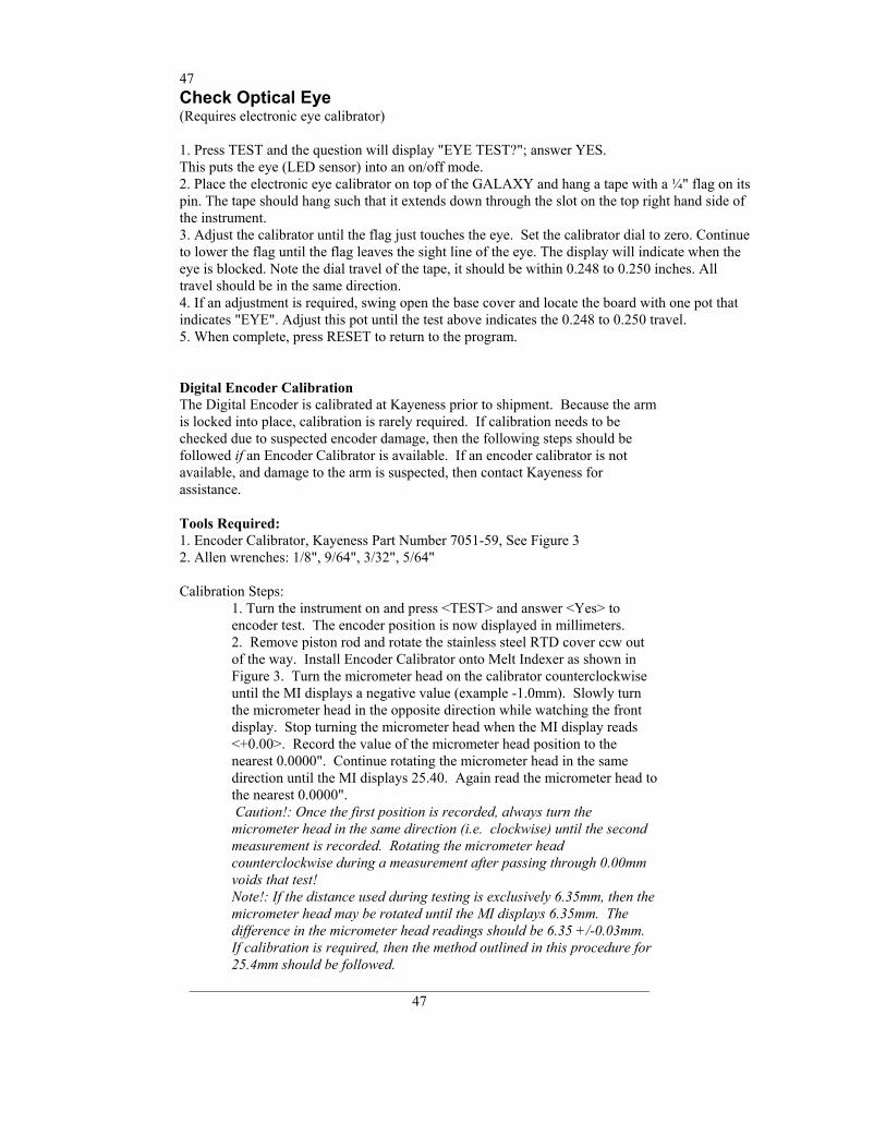
47
_______________________________________________________________ 47
Check Optical Eye (Requires electronic eye calibrator) 1. Press TEST and the question will display "EYE TEST?"; answer YES. This puts the eye (LED sensor) into an on/off mode. 2. Place the electronic eye calibrator on top of the GALAXY and hang a tape with a ¼" flag on its pin. The tape should hang such that it extends down through the slot on the top right hand side of the instrument. 3. Adjust the calibrator until the flag just touches the eye. Set the calibrator dial to zero. Continue to lower the flag until the flag leaves the sight line of the eye. The display will indicate when the eye is blocked. Note the dial travel of the tape, it should be within 0.248 to 0.250 inches. All travel should be in the same direction. 4. If an adjustment is required, swing open the base cover and locate the board with one pot that indicates "EYE". Adjust this pot until the test above indicates the 0.248 to 0.250 travel. 5. When complete, press RESET to return to the program. Digital Encoder Calibration The Digital Encoder is calibrated at Kayeness prior to shipment. Because the arm is locked into place, calibration is rarely required. If calibration needs to be checked due to suspected encoder damage, then the following steps should be followed if an Encoder Calibrator is available. If an encoder calibrator is not available, and damage to the arm is suspected, then contact Kayeness for assistance. Tools Required: 1. Encoder Calibrator, Kayeness Part Number 7051-59, See Figure 3 2. Allen wrenches: 1/8", 9/64", 3/32", 5/64" Calibration Steps:
1. Turn the instrument on and press <TEST> and answer <Yes> to encoder test. The encoder position is now displayed in millimeters. 2. Remove piston rod and rotate the stainless steel RTD cover ccw out of the way. Install Encoder Calibrator onto Melt Indexer as shown in Figure 3. Turn the micrometer head on the calibrator counterclockwise until the MI displays a negative value (example -1.0mm). Slowly turn the micrometer head in the opposite direction while watching the front display. Stop turning the micrometer head when the MI display reads <+0.00>. Record the value of the micrometer head position to the nearest 0.0000". Continue rotating the micrometer head in the same direction until the MI displays 25.40. Again read the micrometer head to the nearest 0.0000". Caution!: Once the first position is recorded, always turn the micrometer head in the same direction (i.e. clockwise) until the second measurement is recorded. Rotating the micrometer head counterclockwise during a measurement after passing through 0.00mm voids that test! Note!: If the distance used during testing is exclusively 6.35mm, then the micrometer head may be rotated until the MI displays 6.35mm. The difference in the micrometer head readings should be 6.35 +/-0.03mm. If calibration is required, then the method outlined in this procedure for 25.4mm should be followed.
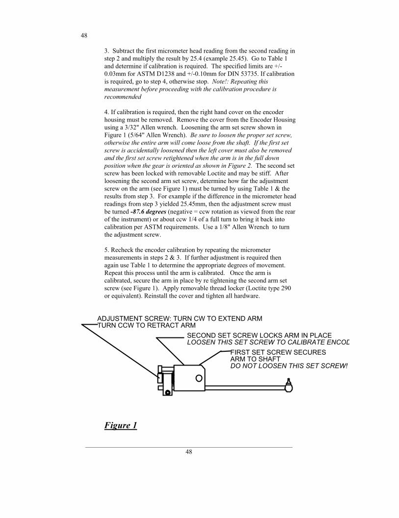
48
_______________________________________________________________ 48
3. Subtract the first micrometer head reading from the second reading in step 2 and multiply the result by 25.4 (example 25.45). Go to Table 1 and determine if calibration is required. The specified limits are +/-0.03mm for ASTM D1238 and +/-0.10mm for DIN 53735. If calibration is required, go to step 4, otherwise stop. Note!: Repeating this measurement before proceeding with the calibration procedure is recommended 4. If calibration is required, then the right hand cover on the encoder housing must be removed. Remove the cover from the Encoder Housing using a 3/32" Allen wrench. Loosening the arm set screw shown in Figure 1 (5/64" Allen Wrench). Be sure to loosen the proper set screw, otherwise the entire arm will come loose from the shaft. If the first set screw is accidentally loosened then the left cover must also be removed and the first set screw retightened when the arm is in the full down position when the gear is oriented as shown in Figure 2. The second set screw has been locked with removable Loctite and may be stiff. After loosening the second arm set screw, determine how far the adjustment screw on the arm (see Figure 1) must be turned by using Table 1 & the results from step 3. For example if the difference in the micrometer head readings from step 3 yielded 25.45mm, then the adjustment screw must be turned -87.6 degrees (negative = ccw rotation as viewed from the rear of the instrument) or about ccw 1/4 of a full turn to bring it back into calibration per ASTM requirements. Use a 1/8" Allen Wrench to turn the adjustment screw. 5. Recheck the encoder calibration by repeating the micrometer measurements in steps 2 & 3. If further adjustment is required then again use Table 1 to determine the appropriate degrees of movement. Repeat this process until the arm is calibrated. Once the arm is calibrated, secure the arm in place by re tightening the second arm set screw (see Figure 1). Apply removable thread locker (Loctite type 290 or equivalent). Reinstall the cover and tighten all hardware.
FIRST SET SCREW SECURESARM TO SHAFT
SECOND SET SCREW LOCKS ARM IN PLACE
ADJUSTMENT SCREW: TURN CW TO EXTEND ARMTURN CCW TO RETRACT ARM
DO NOT LOOSEN THIS SET SCREW!
LOOSEN THIS SET SCREW TO CALIBRATE ENCOD
Figure 1
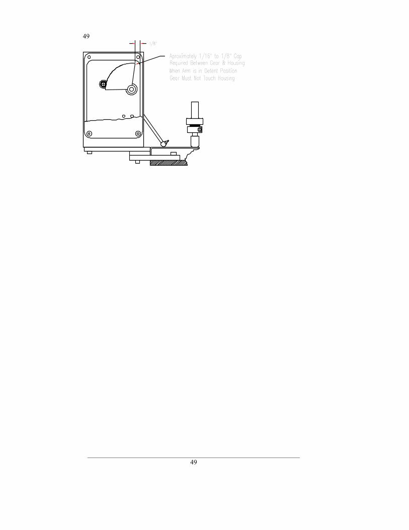
49
_______________________________________________________________ 49
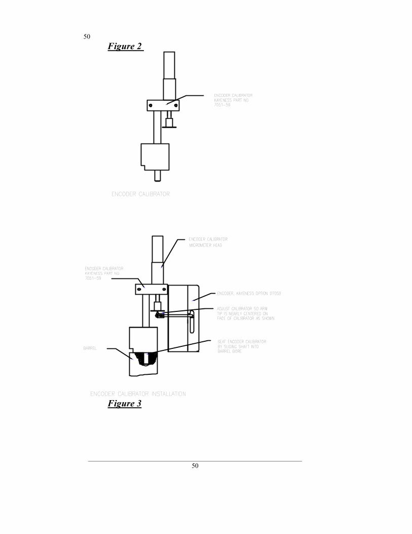
50
_______________________________________________________________ 50
Figure 2
Figure 3
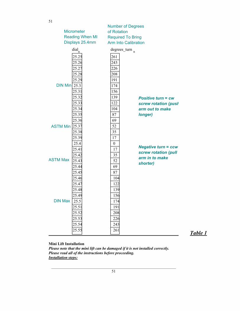
51
_______________________________________________________________ 51
Number of Degrees of Rotation Required To Bring Arm Into Calibration
Micrometer Reading When MI Displays 25.4mm
dialn25.2525.2625.2725.2825.2925.325.3125.3225.3325.3425.3525.3625.3725.3825.3925.425.4125.4225.4325.4425.4525.4625.4725.4825.4925.525.5125.5225.5325.5425.55
degrees_turn n
261243226208191174156139122104876952351701735526987104122139156174191208226243261
DIN Min
Positive turn = cw screw rotation (pusharm out to make longer)
ASTM Min
Negative turn = ccw screw rotation (pull arm in to make shorter)
ASTM Max
DIN Max
Table 1 Mini Lift Installation Please note that the mini lift can be damaged if it is not installed correctly. Please read all of the instructions before proceeding. Installation steps:
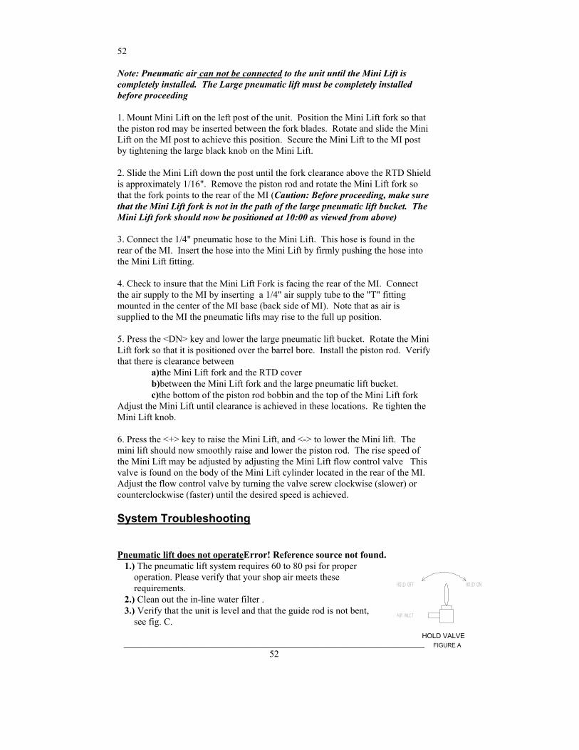
52
_______________________________________________________________ 52
Note: Pneumatic air can not be connected to the unit until the Mini Lift is completely installed. The Large pneumatic lift must be completely installed before proceeding 1. Mount Mini Lift on the left post of the unit. Position the Mini Lift fork so that the piston rod may be inserted between the fork blades. Rotate and slide the Mini Lift on the MI post to achieve this position. Secure the Mini Lift to the MI post by tightening the large black knob on the Mini Lift. 2. Slide the Mini Lift down the post until the fork clearance above the RTD Shield is approximately 1/16". Remove the piston rod and rotate the Mini Lift fork so that the fork points to the rear of the MI (Caution: Before proceeding, make sure that the Mini Lift fork is not in the path of the large pneumatic lift bucket. The Mini Lift fork should now be positioned at 10:00 as viewed from above) 3. Connect the 1/4" pneumatic hose to the Mini Lift. This hose is found in the rear of the MI. Insert the hose into the Mini Lift by firmly pushing the hose into the Mini Lift fitting. 4. Check to insure that the Mini Lift Fork is facing the rear of the MI. Connect the air supply to the MI by inserting a 1/4" air supply tube to the "T" fitting mounted in the center of the MI base (back side of MI). Note that as air is supplied to the MI the pneumatic lifts may rise to the full up position. 5. Press the <DN> key and lower the large pneumatic lift bucket. Rotate the Mini Lift fork so that it is positioned over the barrel bore. Install the piston rod. Verify that there is clearance between a)the Mini Lift fork and the RTD cover b)between the Mini Lift fork and the large pneumatic lift bucket. c)the bottom of the piston rod bobbin and the top of the Mini Lift fork Adjust the Mini Lift until clearance is achieved in these locations. Re tighten the Mini Lift knob. 6. Press the <+> key to raise the Mini Lift, and <-> to lower the Mini lift. The mini lift should now smoothly raise and lower the piston rod. The rise speed of the Mini Lift may be adjusted by adjusting the Mini Lift flow control valve This valve is found on the body of the Mini Lift cylinder located in the rear of the MI. Adjust the flow control valve by turning the valve screw clockwise (slower) or counterclockwise (faster) until the desired speed is achieved.
System Troubleshooting
Pneumatic lift does not operateError! Reference source not found. 1.) The pneumatic lift system requires 60 to 80 psi for proper operation. Please verify that your shop air meets these requirements. 2.) Clean out the in-line water filter . 3.) Verify that the unit is level and that the guide rod is not bent, see fig. C.
HOLD VALVEFIGURE A
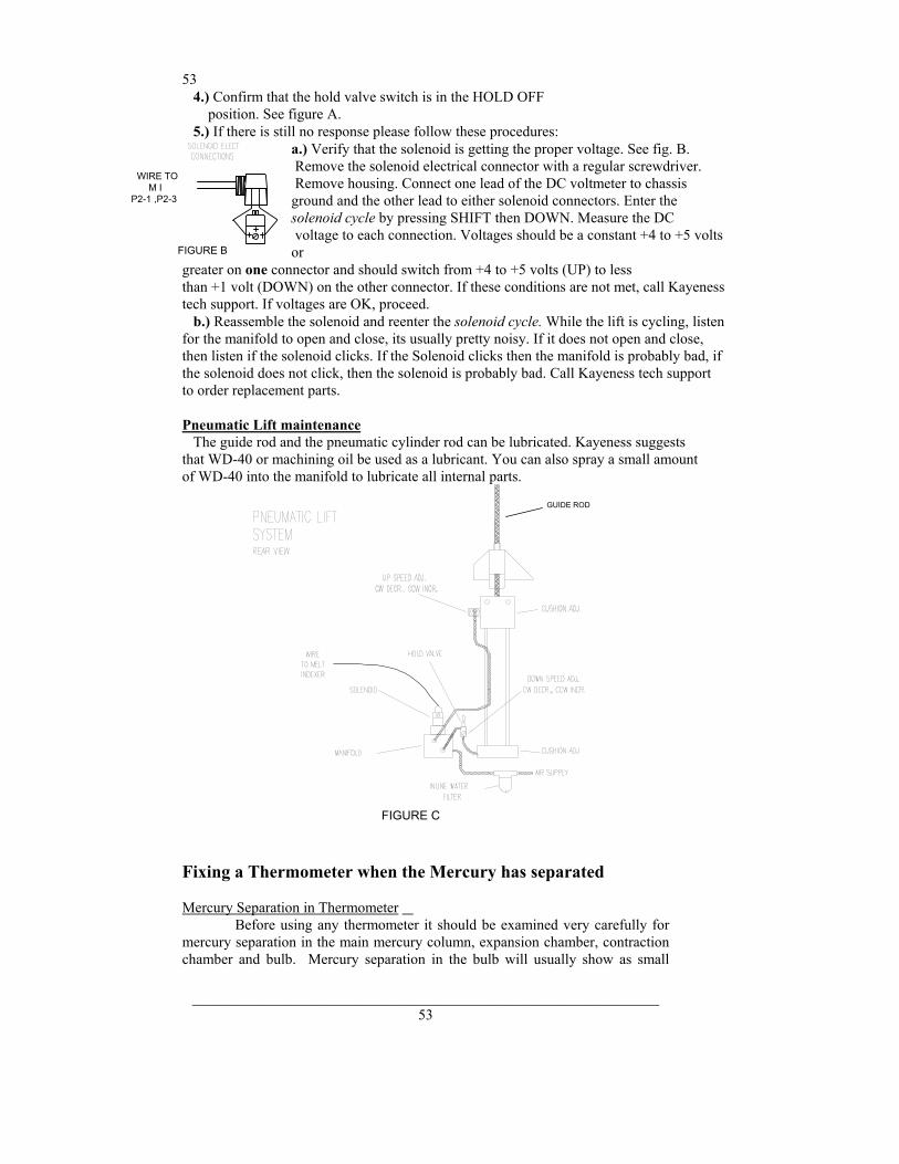
53
_______________________________________________________________ 53
4.) Confirm that the hold valve switch is in the HOLD OFF position. See figure A. 5.) If there is still no response please follow these procedures:
a.) Verify that the solenoid is getting the proper voltage. See fig. B. Remove the solenoid electrical connector with a regular screwdriver. Remove housing. Connect one lead of the DC voltmeter to chassis ground and the other lead to either solenoid connectors. Enter the solenoid cycle by pressing SHIFT then DOWN. Measure the DC voltage to each connection. Voltages should be a constant +4 to +5 volts or
greater on one connector and should switch from +4 to +5 volts (UP) to less than +1 volt (DOWN) on the other connector. If these conditions are not met, call Kayeness tech support. If voltages are OK, proceed. b.) Reassemble the solenoid and reenter the solenoid cycle. While the lift is cycling, listen for the manifold to open and close, its usually pretty noisy. If it does not open and close, then listen if the solenoid clicks. If the Solenoid clicks then the manifold is probably bad, if the solenoid does not click, then the solenoid is probably bad. Call Kayeness tech support to order replacement parts. Pneumatic Lift maintenance The guide rod and the pneumatic cylinder rod can be lubricated. Kayeness suggests that WD-40 or machining oil be used as a lubricant. You can also spray a small amount of WD-40 into the manifold to lubricate all internal parts.
FIGURE C
GUIDE ROD
Fixing a Thermometer when the Mercury has separated Mercury Separation in Thermometer Before using any thermometer it should be examined very carefully for mercury separation in the main mercury column, expansion chamber, contraction chamber and bulb. Mercury separation in the bulb will usually show as small
WIRE TOM I
P2-1 ,P2-3
FIGURE B
54
_______________________________________________________________ 54
bubbles. All the mercury must be united. If a thermometer does not read zero at the ice point mercury separation is typically the cause. There is no known method to completely insure that the mercury will not separate in a thermometer when the thermometer is subjected to shock. This can occur either in transit or by improper storage and handling in reuniting a separated mercury column. Remember that the thermometer contains only two fluids, mercury and gas. The object is to get all the liquid below the gas or, conversely all the gas above the liquid. Cooling Method for Reuniting Mercury Thermometers This method is the easiest to use and is the method PRINCO recommends. In a small Dewar flask or thermos bottle mix powdered dry ice with Methanol or Acetone. Holding the thermometer vertical, immerse about 3/4 of the lower section of the bulb into the mixture. DO NOT immerse the capillary or funnel section that is above the bulb into the mixture. The main portion of the mercury will retreat into the bulb, and the separated portion will follow. Occasionally the separated portion may cling to the walls of the funnel portion of the bulb. When all the mercury, including the separated portion, has retreated into the bulb, remove the thermometer from the dry ice mixture. The mercury should go together. Stand the thermometer in a vertical position and allow the mercury to rise into the capillary of its own accord. DO NOT TOUCH THE BULB WITH YOUR HANDS! If you are unsuccessful repeat the cooling method except this time gently tap (do not bounce) the thermometer bulb vertically on a desk pad after removing from the flask. NOTE: Where possible, thermometers should be stored in a vertical position.
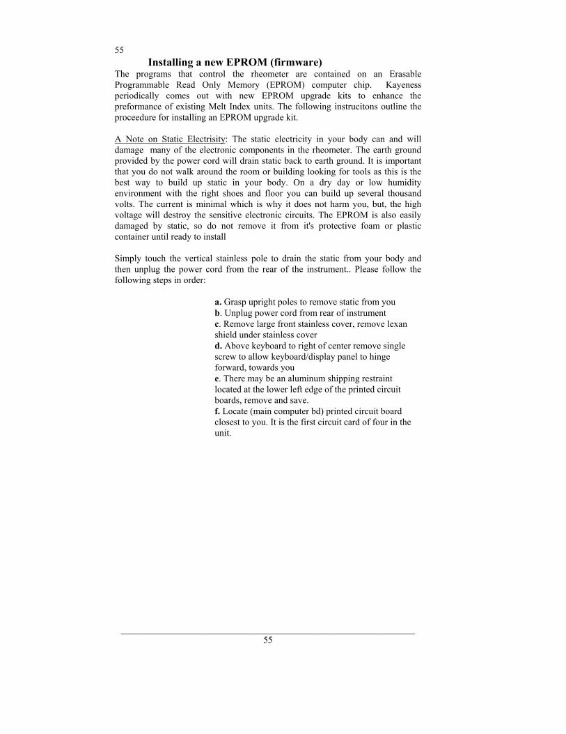
55
_______________________________________________________________ 55
Installing a new EPROM (firmware) The programs that control the rheometer are contained on an Erasable Programmable Read Only Memory (EPROM) computer chip. Kayeness periodically comes out with new EPROM upgrade kits to enhance the preformance of existing Melt Index units. The following instrucitons outline the proceedure for installing an EPROM upgrade kit. A Note on Static Electrisity: The static electricity in your body can and will damage many of the electronic components in the rheometer. The earth ground provided by the power cord will drain static back to earth ground. It is important that you do not walk around the room or building looking for tools as this is the best way to build up static in your body. On a dry day or low humidity environment with the right shoes and floor you can build up several thousand volts. The current is minimal which is why it does not harm you, but, the high voltage will destroy the sensitive electronic circuits. The EPROM is also easily damaged by static, so do not remove it from it's protective foam or plastic container until ready to install Simply touch the vertical stainless pole to drain the static from your body and then unplug the power cord from the rear of the instrument.. Please follow the following steps in order:
a. Grasp upright poles to remove static from you b. Unplug power cord from rear of instrument c. Remove large front stainless cover, remove lexan shield under stainless cover d. Above keyboard to right of center remove single screw to allow keyboard/display panel to hinge forward, towards you e. There may be an aluminum shipping restraint located at the lower left edge of the printed circuit boards, remove and save. f. Locate (main computer bd) printed circuit board closest to you. It is the first circuit card of four in the unit.
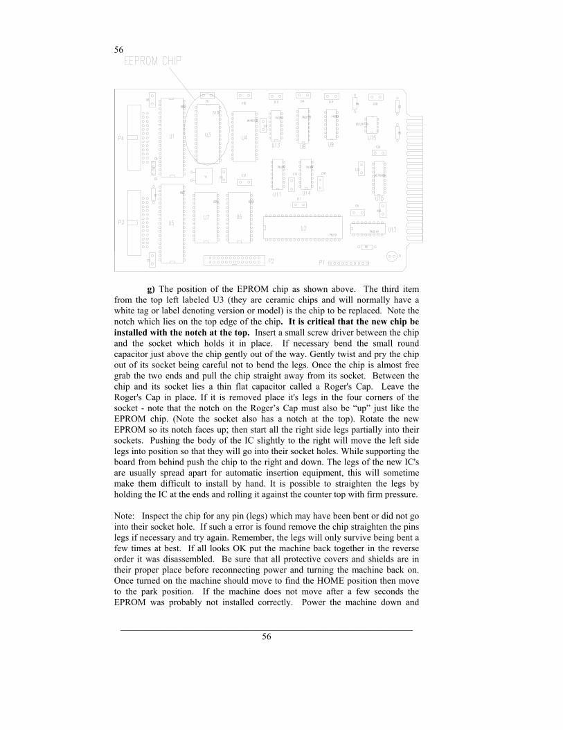
56
_______________________________________________________________ 56
g) The position of the EPROM chip as shown above. The third item from the top left labeled U3 (they are ceramic chips and will normally have a white tag or label denoting version or model) is the chip to be replaced. Note the notch which lies on the top edge of the chip. It is critical that the new chip be installed with the notch at the top. Insert a small screw driver between the chip and the socket which holds it in place. If necessary bend the small round capacitor just above the chip gently out of the way. Gently twist and pry the chip out of its socket being careful not to bend the legs. Once the chip is almost free grab the two ends and pull the chip straight away from its socket. Between the chip and its socket lies a thin flat capacitor called a Roger's Cap. Leave the Roger's Cap in place. If it is removed place it's legs in the four corners of the socket - note that the notch on the Roger’s Cap must also be “up” just like the EPROM chip. (Note the socket also has a notch at the top). Rotate the new EPROM so its notch faces up; then start all the right side legs partially into their sockets. Pushing the body of the IC slightly to the right will move the left side legs into position so that they will go into their socket holes. While supporting the board from behind push the chip to the right and down. The legs of the new IC's are usually spread apart for automatic insertion equipment, this will sometime make them difficult to install by hand. It is possible to straighten the legs by holding the IC at the ends and rolling it against the counter top with firm pressure. Note: Inspect the chip for any pin (legs) which may have been bent or did not go into their socket hole. If such a error is found remove the chip straighten the pins legs if necessary and try again. Remember, the legs will only survive being bent a few times at best. If all looks OK put the machine back together in the reverse order it was disassembled. Be sure that all protective covers and shields are in their proper place before reconnecting power and turning the machine back on. Once turned on the machine should move to find the HOME position then move to the park position. If the machine does not move after a few seconds the EPROM was probably not installed correctly. Power the machine down and
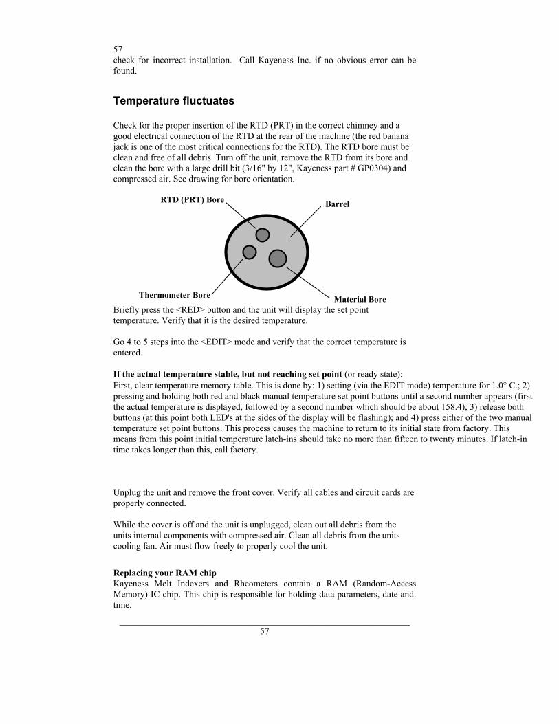
57
_______________________________________________________________ 57
check for incorrect installation. Call Kayeness Inc. if no obvious error can be found.
Temperature fluctuates Check for the proper insertion of the RTD (PRT) in the correct chimney and a good electrical connection of the RTD at the rear of the machine (the red banana jack is one of the most critical connections for the RTD). The RTD bore must be clean and free of all debris. Turn off the unit, remove the RTD from its bore and clean the bore with a large drill bit (3/16" by 12", Kayeness part # GP0304) and compressed air. See drawing for bore orientation.
RTD (PRT) Bore Barrel
Material BoreThermometer Bore
Briefly press the <RED> button and the unit will display the set point temperature. Verify that it is the desired temperature. Go 4 to 5 steps into the <EDIT> mode and verify that the correct temperature is entered. If the actual temperature stable, but not reaching set point (or ready state): First, clear temperature memory table. This is done by: 1) setting (via the EDIT mode) temperature for 1.0° C.; 2) pressing and holding both red and black manual temperature set point buttons until a second number appears (first the actual temperature is displayed, followed by a second number which should be about 158.4); 3) release both buttons (at this point both LED's at the sides of the display will be flashing); and 4) press either of the two manual temperature set point buttons. This process causes the machine to return to its initial state from factory. This means from this point initial temperature latch-ins should take no more than fifteen to twenty minutes. If latch-in time takes longer than this, call factory. Unplug the unit and remove the front cover. Verify all cables and circuit cards are properly connected. While the cover is off and the unit is unplugged, clean out all debris from the units internal components with compressed air. Clean all debris from the units cooling fan. Air must flow freely to properly cool the unit.
Replacing your RAM chip Kayeness Melt Indexers and Rheometers contain a RAM (Random-Access Memory) IC chip. This chip is responsible for holding data parameters, date and. time.
58
_______________________________________________________________ 58
Follow these instructions: 1. Make sure you have a hard copy of all your test parameters. 2. Briefly touch the poles of the instrument to discharge any static electricity built up on your body. Turn off and unplug the machine. 3. Detach the stainless steel cover on the machine by removing the screws located on the side of the machine. You only need to remove the front cover on Capillary Rheometers. 4. Remove the front panel bolt with a one-eighths inch (1/8") Allen wrench and swing open the front panel. 5. The electronics card, known as Computer Board One, located second from the front of the machine, contains the RAM. Remove the electronics safety shield and the board clamp mounted on the base of the machine. Remove all of the connectors leading to CB1 taking note of where they where originally connected, and remove the board. 6. Locate the RAM on CB1. It is clearly marked on the schematic you received and is identified physically by being taller than most of the other IC's that populate the board. Note the notch or small circle on top of the old IC. The new chip's notch or small circle should physically be in the same place as the original. Remove the chip by gently prying underneath it with a medium size screwdriver and replace it with the new chip. Take care not to bend any of the legs of the IC when replacing it. 7. Reassemble the machine. When you power up the machine it is important to perform a memory clear. Press SHIFT , NO and answer YES to the clear all memory prompt. You are now ready to reprogram your unit.
59
_______________________________________________________________ 59
Inconsistent Flow Rates Cleanliness of the barrel and components is a critical factor in the behavior of materials. The barrel of the unit should be cleaned as well as possible. All components associated with the instrument (Piston tip and Orifice) should be cleaned of all debris and material build-up. Next, the units component tolerances and operational components should be checked: • The barrel temperature should be checked with the supplied
thermometer.(+/- 0.2° C) • The orifice should be checked for wear with the supplied GO-NO GO gauge.(0.0825 +/-0.0002
in.) • The piston tip should be checked for correct tolerances.(MI 0.3730 +/-0.003 in.) • The guide bushing should be clean of material and easily slide up and down the
piston rod. • If running method B tests, are the factory supplied flags in good condition. • The machine should be on a level surface.(Vertical alignment of the bore) The precision and accuracy of the test and instrument has been assessed by ASTM D1238 et. al. Kayeness has found that the contributing factors to the accuracy of the test includes sample charge (the amount of material tested), timing (how long the material is in the heated barrel), packing technique, dryness (has the material been properly dried), cleaning and cutting technique. It is recommended to follow ASTM Specification D1238 for your material or control sample. Also, attention should be given to the recommendations of the material manufacturer or suppliers.
60
_______________________________________________________________ 60
After a good cleaning and purge, your control sample should be run a minimum of 5 times to verify that the problem is repeatable or even exists. If you feel it is necessary to call the factory, please have your model number, serial number and a complete program listing available (it may be helpful to fax the program data) when you call.
Accuracy and Reproducibility Precision In our inhouse labs we have found the same machine day-to-day reproducibility of the apparent shear viscosity in shear rate ranges of 10 to 1000 to be about 1.5 to 2.0% ( 1 standard deviation over the mean viscosity value, pooled estimate). The variation tends to increase very quickly at lower rates. This variation value is the same range found by 17 labs participating in the D3835 round robin testing in 1991.1 This 2% value is used in the reduced chi square estimate (RCS) shown with the fitted information in KARS. The RCS tells how many standard deviation the fitted curve is away from the typical standard deviation of a point. The machine to machine reproducibility (for all capillary rheometers in general, according to ASTM) is significantly higher and the latest values are included in ASTM D3835 precision and bias statement found at the end of the ASTM document. This value is on the order of 8%. See ASTM method D3835 (attached) for a graphical display of round robin results. Accuracy The RTD'S on Kayeness Inc. machines are calibrated to NIST traceable standard temperature boxes which are recalibrated every 6 mo. by NIST. Die diameters are checked with hardened, class X gage pins (+/- 20 millionths accuracy). Die lengths are checked with micrometers for flat dies. For those with entrance cones a matching cone is inserted and the overall length measured. Capillary length is back calculated through trigonometry . Piston tips and length are check with hand micrometers or laser micrometers. Force cells are calibrated using a calibration cell which is calibrated with dead weights that are NIST traceable. Accurate die diameter measurements, particularly at very small die diameters, is the most critical item for achieving accurate results. NIST does provide standard reference materials for melt indexers which can be used on rheometers though they tend to be expensive. ASTM also has a group of standard materials for those who wish to participate in round robins, all are welcome to contact the current chairperson of D20.30.08 to get involved. Many of these material are used as Indexer standards as well and can be used as a good bridge in going from Indexer to more controlled capillary rheometry .
Barrel Drawing
1Report on file at ASTM headquarters, 1916 Race St., Philadelphia, Pa. 19103-1187 (215) 299-5529
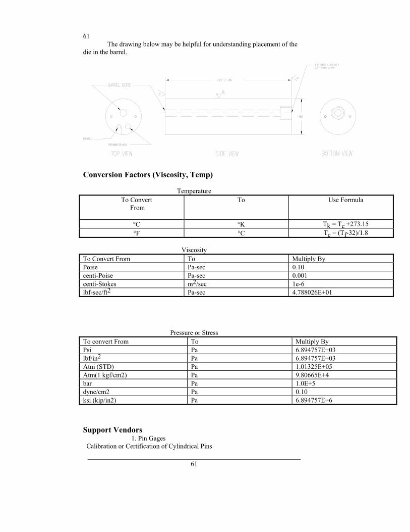
61
_______________________________________________________________ 61
The drawing below may be helpful for understanding placement of the die in the barrel.
Conversion Factors (Viscosity, Temp)
Temperature To Convert
From
To Use Formula
°C °K Tk = Tc +273.15 °F °C Tc = (Tf-32)/1.8
Viscosity
To Convert From To Multiply By Poise Pa-sec 0.10 centi-Poise Pa-sec 0.001 centi-Stokes m2/sec 1e-6 lbf-sec/ft2 Pa-sec 4.788026E+01
Pressure or Stress To convert From To Multiply By Psi Pa 6.894757E+03 lbf/in2 Pa 6.894757E+03 Atm (STD) Pa 1.01325E+05 Atm(1 kgf/cm2) Pa 9.80665E+4 bar Pa 1.0E+5 dyne/cm2 Pa 0.10 ksi (kip/in2) Pa 6.894757E+6
Support Vendors 1. Pin Gages
Calibration or Certification of Cylindrical Pins
62
_______________________________________________________________ 62
Zero Check POB 903 Thomaston, Connecticut 06787 Tel:203-283-5629 FAX: 203-283-4113 Contact: Louise. Meyer Gage Company 230 Burnham St. South Windsor, CT 06074 (203) 528-6526 Ask for Class X pins (ISO specs are ± 0.0002 of nominal, ASTM specs (D3835) are ± 0.0003 of nominal)
2. Cleaning Patches Skyline Center Inc. POB 3064 Clinton, IA 52732 (319) 243-4065 (800) 747-4065 Extension-4065 FAX (319) 243-9901
3. Bore Gages Inspex Corp 664 Bussee Hwy Park Ridge, IL 60068 (708) 825-2200, Fax 825-0825 Order Diameter Probe #029 Probe, N-6 Needle, 0.0001 dial indicator, 8mm holder, #029 ring (0.375"), 0.315" x 10" Depth Extension 4. NIST Standard Reference Materials (SRM)
For example: Standard Material 1476 is a branched polyethylene with (a MFR of 1.19 ± 0.01) as of 1992 cost about $255 for 50 grams. SRM Catalog number is NIST Special Publication 260 To order: (301) 975-6776 Fax (301) 948-3730
5. Hg spill kits Mercury Clean Up Spill Kits Mercon Products: distributed by Fisher Scientific Unit 8, 7551 Vantage Way Delta, B.C. Canada V4G 1C9 Tech Assistance (800)926-8999 (604) 940-0975 or call Fisher Scientific PRINCO Instruments Inc. (Accepts Hg for Recycle) 1020 Industrial Highway Southampton, PA 18966
63
_______________________________________________________________ 63
(215) 355-1500
ASTM Melt Indexer Testing Specification D1238 The following capillary rheometer test method is reprinted , with permission, from the Annual Book of ASTM Standards, copyright American Society for Testing and Materials, 1916 Race Street, Philadelphia, PA 19103
Answers to Common Questions
Question:I pressed RUN the machine appeared to start but now it just sits there saying Printing on the front display!? Answer: The instrument is trying to communicate with the Personal Computer (PC) or printer it must communicate with it before the test starts. Either: 1) the software is not running on the PC; 2) the cable connection or communications port on the PC is faulty; 3) the Printer is not conected or turn off attached option (under SHIFT PRNT) is set ON when it should be set OFF because the machine is not attached to a PC. Question: The temperature used to be very stable on the machine now it seems to vary more than +/- 0.2 degrees when just sitting there. (not loading sample or cleaning barrel) Answer: The hole that the temperature measurement probe sits in may be contaminated with material. Set the current machine temperature to 0.0 then and only then remove the temperature probe (RTD), wipe it clean if necessary and use a long drill bit to remove any material down the RTD measurement hole. Question: How do I check the temperature? Answer: You received with the machine a mercury thermometer. This thermometer comes with a calibration certificate from KAYENESS comparing it to our NIST traceable reference box. Any deviation from our NIST traceable box will be noted and supplied with the thermometer. Set the machine to the temperature of the reference thermometer (see thermometer markings). Let the machine come to temperature. Only after the machine is stable insert the thermometer gently down the thermometer well which lies under an Allen screw cap, directly adjacent to the RTD probe, on the top of the rheometer barrel.
Question: My method B numbers are wrong after inputting my manufacturers value for the apparent melt density. Why is this? Answer The manufacturer's value is probably based on the solid state density of the material, not the melt density. An A/B method should always be run before method B only tests are conducted. This is the only way to be sure that your method B values are correct. Question: My MFI is changing. Why?

64
_______________________________________________________________ 64
Answer: The most common cause to this problem is not keeping the barrel and die properly cleaned. The power cleaning kit (PN 8052-97K) is very much recomended to help promote a clean system. Question: What flag do I use? Answer: Please refer to page 28 of the manual. Customers with the digital encoder option (PN D7059) do not need to pick a flag - it is done automatically. Digital encoder systems do not eveh have the slot for the flag! Question: I am running a Method A test. How long should my cut time be? Answer: Kayeness suggests that you collect 1 gram or more of material before making your cut. Question: My printer does not work. What gives? Answer: Make sure that the Printer option is turned on (Shift-Print). Customers with the Mini-Printer option must make sure that the mini-printer is turned on BEFORE the Melt Indexer is turned on.
65
_______________________________________________________________ 65
Glossary Firmware Flow Ratio Since polymers exhibit non-Newtonian behavior (i.e., flow rate varies as a function of shear stress), the single rate defined by a normal flow rate test does not represent the overall character of a polymer. Flow rate ratio was developed to help further define polymer character by measuring flow rate at two loads (two different shear stresses). To calculate flow rate ratio, the second flow rate is simply divided by the first. The second load is generally 10 times the first, hence it is referred to as the I-10 test. The ratio is referred to as I10/I2. Kayeness Specific Melt Indexer Terminology Mtd A Time B Time Start Pos Flag Polymer Science Terminology I.V. Molecular weight Molecular weight distribution General Melt Indexer Terminology Melt Index Melt Flow Rate Melt Flow Volume Extrudate Melt Time Flow Rate Ratio Flow rate ratio is simply the division of a flow rate obtained at a high load by flow rate obtained at a lower load. The load ratio is generally 10 to 1. The KAYENESS GALAXY I system is set up to do flow rate ratio in a single run. The slope of the log shear rate vs log viscosity data has been shown to correlate with molecular weight distribution for Polypropylene samples when loads ocrresponding to 30 and 15 kPa are used at 230°C.

66
_______________________________________________________________ 66
A A Accuracy and Reproducibility, 64 action list, 38 An Overview of MI, 17 B Bench Requirements and Placement, 8 C Calculations : Method A/B, 32 Calculations : Method B, 25 Calculations: Method A, 20 Charge Weight, 36 Check List, 39 Clean the Barrel, 12 Cleaning Up, 23, 30 Cleaning Up a really Big Mess, 24 Computer connection, 9 Conversion Factors, 65 D DATE, 19 DEL, 19 Die Dimensional Checks, 49 DN, 18 E EDIT, 17, 18 Electrical Hazard, 14 Encoder Calibration, 50 Encoder Installation, 10 END, 19 EPROM, 59 F Firmware Defaults, 13 Flag, 28 Flow Rate Ratio, 43 Fumes from Materials, 15 G gloves, 14 I I.V., 44 ID, 19 K KAYENESS Inc., 5 L Level the Melt Indexer, 8 Loading the Barrel, 22, 29, 33 M Maintenance, 47 Making the Cut, 23, 35 melt density, 25 Mercury, 14 mercury thermometers, 14 Method, 20, 25, 32

67
_______________________________________________________________ 67
Method B Encoder Option, 7 Mini Lift, 54 minilift, 18 Model Descriptions, 6 Muffler installation, 11 Multi Weight, 44 Multiple Method A/B, 43 N NO, 19 O Optical Eye, 50 out-of-control, 38 Oven cleaner, 24 P Pa-sec, 65 Pneumatic Lift, 56 Poise, 65 Power Cleaning Tool, 9 Power Cord, 9 PRGM, 18 PRINT, 19 Prtinter Connection, 9 Purging the Barrel, 16 PVC, 15 R RAM chip, 61 RESET, 18 RTD, 15 RTD Connection, 9 RUN, 18 S SAFETY, 14 Safety Check, 16 SHIFT, 18 SHIFT - NO, 19 SHIFT - PRINT, 18 SKIP, 19 Software installation, 11 Standard Operating Procedure, 37 Standard Tool Set, 4 Support Vendors, 65 System Troubleshooting, 56 T Temperature Calibration, 47 TEST, 18 Timing Flag, 28 Turning on the Indexer, 12 Typographic Conventions, 5 U Unpacking the Indexer, 8 Y YES, 19

68
_______________________________________________________________ 68


![(RON) 14AUG 0.95 1.01 1.05 1.05 1.05 1.04 2.3% PSB Industries [FR] 11.6x 1.3x … · 2017-08-14 · APS (RON) 0.95 1.01 1.05 1.05 1.05 1.04 2.3% 11.6x 1.3x ROaE À 8.2% 0.7% 0.8%](https://img.pdfslide.net/doc/110x75/5f7f1b4bb4b94c6a071b1181/ron-14aug-095-101-105-105-105-104-23-psb-industries-fr-116x-13x-2017-08-14.jpg)